Embed Size (px)
Citation preview
MIL-STD-1186A
12 March 1981
SUPERSEDIliG-
MIL-STD-1186
28 October 1963
MILITARY STANDARD
cUsHIoNx~G, A~cHoRI~/G, BRACING, BLOCKING
A?ll\’ATERPROOFING; ‘!Ill{NPROPPIATE TEST METHODS
FSC PACK
Downloaded from http://www.everyspec.com
MIL-STD-1186A
12 March 1981
DEPARTMENT OF DEFENSE
Washington, D*C. 20301
Cushioning, Anchoring, Bracing, Blocking and k!aterproofing; with
Appropriate Test Methods
MIL-STD-1186A
1. This i;ilitary Standard is approved ior use bY all Departments and Agencies
of the Department of Defense.
7k ● Beneficial comments (recommendations> additions) deletions) and any
pertinent data which may be of use in improving this document should be
addressed to: LTSArmv Mobility Equipment I?esearchand Development Command,.ATTN : DRDME-DS, Fort Belvoir, VA ~2060 by using the self-addressed
Standardization Document Improvement Proposal (DD Form 1426) appearing at the
end of this document or by letter.
ii
-.
Downloaded from http://www.everyspec.com
.
TABLE OF CONTENTS
MIL-STD-1186A
12 March 1981
PARAGRAPH 1.
-)L*
3.
-4.
4.1
4.2
4,3
4.4
5.
5*1
5.1.1
5.1.2
5.1.3
5.1.4
5.1.5
5.2.1
5.2.2
5.3
SCOPE
.4PPLI(’ABLEI?OCUMENTS
DEFINITIONS
Dangerous Articles
Weight Limitations
Performance
DETAILED REQUIREMENTS
Arrangement of Contents
Disassembled Parts
Moveable Parts and Projection Parts
Segregation of Packaged Contents
Conversion of Type 3 I,oads
Surface Corrosion
Cushioning
Flotation or Suspension
Abrasion Protection
Coating and Barriers
Moisture Resistance
Dusting
Blocking and Bracing
PAGE
1
3
3
3
3
3
3
4
4
4
4
4
4
4
5
5
5
5
5
5
iii
Downloaded from http://www.everyspec.com
MIL-STD-1186A
12 March 1981
PARAGRAPH 503.1
5,3*Z
5.3.3
5.3.4
5.3.5
5.3.6
5.4
5.4.1
5.4.2
5*5
5.6
5.6.1
5.6.2
5.6.3
FIGURE 1
2
3
4
TABLE OF CONTENTS
Surface Abrasion and Corrosion
Corrugated Fiberboard Fores
Other Rigid, Low-density Materials
Wood and Pl~ood
Nails and Nailing
Bolt Application
Anchoring
Anchor Bolts
Metal Strapping
Clearances
Waterproofing
Lines and Linings
Waterproof and Water-Proof Wraps
Shrouds
PAGE
5
6 -
11
13
13
14
15
16
16
16
17
17
FIGURES
Trays and Open-end Cells7
Bracing Supports Shall Bear Directly on 8the Article
10Corrugated Fiberboard Accordian Folded Pads
Multiple-Layer Corrugated Fiberboard Corner Pads 12
Downloaded from http://www.everyspec.com
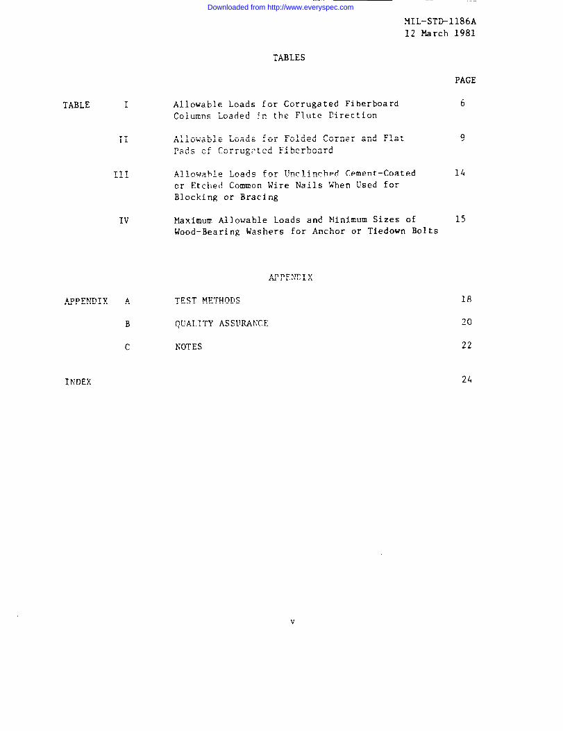
TABLE I
II
III
IV
APPENDIX A
B
c
MIL-STD-1186A
12 March 1981
TABLES
Allowable Loads for Corrugated Fiberboard
Cclumns Loaded ~n the Flute Direction
Allowable Loads for FolciedCorner and Flat
Pads of Corrugated Fiberboard
Allowable Loads for Unclinched Cement-Coated
or Etched Common Wire Nails When Used forBlocking or Bracing
PAGE
6
9
Maximum Allowable Loads and Minimum Sizes of 15
Wood-Bearing Washers for Anchor or Tiedown Bolts
APPENDIX
TEST METHODS
QUALITY ASSURANCE
NOTES
INDEX 24
Downloaded from http://www.everyspec.com
MXL-STP1186A
12 March 1981
1. SCOPE
1.1 Scope. This standard covers common packing requirements which may be
omitted from detailed specifications for items or categories of items when thisstandard is referenced in the detail specification. It does not contain require-
ments for shipping containers themselves or for preservations of items both ofwhich may also provide physical protection. Tests for determining the adequacy
of the protective measures to prevent damage to the items or materials
(barriers) are included in Appendix A. Quality Assurance provisions are givenin Appendix B and forms a mandatory part of this standard. Appendix C is forgeneral information only.
1.2 Application. The requirements contained herein are confined to the pro-
tective measures applied to items in their shipping configuration and whenapplicable, this document should be specified in the packing section of procure-
ment documents.
2. APPLICABLE DOCUMENTS
2.1 Issues of documents.date of invitation for bidsspecification to the extent
SPECIFICATIONS
FEDERAL
L-P-378
FF-B-584
FF-N-]OT
FF-W-92NN-P-530
QQ-S-781TT-I-1795
UU-T-81MMM-A-260
PPP-B-1055PPP-C-843
PPP-C-850
PPP-C-1120
PPP-F-320
The following documents of the issue in effect onor request for proposal form a part of thisspecified herein.
- Plastic Sheet and Strip, ~“hinGauge, Polyo-
lefin.- Bolts, Finned }/eck,Key Head, Machine, Ribbed
Neck, Square Neck, Tee Head.- Nail, Brads, Straples and Spikes, Wire, Cutand Wrought.
- Washer, Metal, Flat (Plain).- Plywood, Flat Panel.- Strapping, Steel and Seals.- Ink, Marking, Stencil Opaque (Porous and
Nonporous Surfaces).- Tag, Shipping and Stocks.
- Adhesive, Water Resistant, (For SealingWaterproof Paper).
- Barrier Material, Waterproofed, Flexible.
- Cushioning Material, Cellulosic.
- Cushioning Material, Polystyrene Expanded,Resident (For Packaging Uses).
- Cushioning Mterial, Uncompressed Bound Fiberfor Packaging.
- Fiberboard, Corrugated and Solid, Sheet Stock(Container Grade), and Cut Shapes.
1
Downloaded from http://www.everyspec.com

MIL-STD-1186A
12 March 1981
MILITARY
MIL-P-116MIL-L-10547
MIL-P-19644
MIL-P-21929
M?L-B-~~~9]
MIL-P-24249
MIL-P-26514
MIL-F-26862
- Preservation-Packaging, Methods of.- Liner, Case, and Sheet, Overwrap, Water
Vaporproof or Waterproof, Flexible.
- Plastic Molding Material (PolystyreneFoam, Expanded Bead).
- Plastic Material, Cellular Polyurethane,Foam-in-Place, Rigid 2 and 4 Pounds per
Cubic Foot.- Barrier Material, Transparent, Flexible,
Heat Sealable.- Plastic Material, Cellular Polyurethane,
Rigid, Void Filler, Pour-in-Place, Large
Scale and Installation of.- Polyurettlane Foam, Rigid or Flexible, for
Packaging.
- Fiberboard, Solid, Non-Corrosive, Fungi-
Resistant for Interior Blocking Applica-
tions.
STANDARDS
FEDERAL
FED-STD-101 – Pr(~qf-~rvatinnj P2rka~in~ and PaCk.i_!’?g
Materials, Test Procedures.
MILITARY
?fTL_sT~–73] - Qllalityof Wood Members for Containers andPallets.
~,~ Other publications. The following documents form a part of this speci-
fication to the extent specified herein. Unless otherwise indicated, the issue
in effect on date of invitation for bids or request for proposal shall applyo
49 CFR 100-199 - Code of Federal Regulations, Title 49, Transporta-tion, Parts 100 to 199.
TM 38-250 (AFR 71-4, NAVSUP PUB 505, MCOP4030.19, DSAM 4145.3) - Packag-ing snd Handling of Dangerous Materials for Trans-
portation by Military Aircraft*
U.S. Department of Agriculture, Forest Products Laboratory, AgricultureHandbook No. 72, Wood Handbook, Wood as an Engineer-
ing Material.
—
Downloaded from http://www.everyspec.com

MIL-STD-1186A
12 March 1981
3. DEFINITIONS
3.1 Anchoring. The securing of an item to its shipping container so as to
prevent any movement of the item within the container.
3.2 Blocking and bracing. A means used to immobilize an item during ship-
ment and storage.
3.3 Cushioning. A means used to absorb the energy of shoclcsand vibrations
through a gradual but increasing resistance to the movement of the item.
3.4 Fragility. The inherent physical properties of an item that limit its
ability to withstand shock or vibration without damage.
3.5 Packaging. The processes and procedures used to protect material from
deterioration and damage, including appropriate cleaning, drying, preserving,packing, marking and unitization.
3.6 Packing. Assembling of items into a unit, intermediate or exterior packwith necessary blocking, bracing, cushioning, anchoring weatherproofing, rein-
forcement and marking.
3.7 Preservation. Application of protective measures, including cleaning,
drying, preservative materials, barrier materials, cushioning, and containerswhen necessary.
4.1 Material. Material shall be as specified herein. Materials not
definitely specified herein shall be as specified by the item specification,contract or order.
4.1.1 Recycled material. It is encouraged that recycled material be usedwhen practical as long as it meets the requirements of the specification.
~.~ Dangerous articles. The packagi~; of commodities in accordance with this
standard which come within the scope of the Interstate Commerce Commission Rules
and Regulations for the Transportation of Explosives or other dangerousarticles, 49CFR-1OO-199, and other applicable documents, shall conform to the
regulations in all respects without exception. In addition, packaging ofdangerous materials for air shipment shall be in accordance with the joint AirForce, Army, Navy Manual, TM 38-250, Packaging and Handling of DangerousMaterials for Transportation by Military Aircraft (AFR 71-4, TM 38-250, NAVSUPPUB 505, MCOP4030.19, DSAM 41453).
4.3 Weight limitations. Whenever design considerations limit the grossweight of individual shipping containers, a maximum gross weight limit shall be
stated in the specification, contract, or order.
4.4 Performance. When packs prepared for shipment in accordance with the
detailed requirements of this standard are tested for any rough handling
3
Downloaded from http://www.everyspec.com

MIL-STD-1186A
12 March 1981
required by the specification, contract, or order, there shall be nc settlementor shifting of the packed item. Further, the testing shall cause no damage to
the item and shall not loosen, break, or displace the anchoring, blocking, or
bracing. The testing shall not render the interior containers, wraps, liners,
barriers, or cushioning ineffectual in providing continued adequate protection
to the contentsc
5. DETAILED REQ[’IREMENTS
5.1 Arrangement of contents. The contents of a pack shall be arranged to
provide the smallest practical cubage, convenient handling, suitability for unit-
ization while permitting a container to be fabricated in the most economicalmethod. The contents shall completely fill the container or be secured therein
with suitable clearance (see 5.5) to prevent damage.
5.1.1 Disassembled parts. When practical, items shall be disassembled to
afford protection of components, attachments, and accessories against damage and
pilferage and to reduce cubage. Disassembled parts shall be preserved,
anchored, braced, blocked, and cushioned to prevent damage. Disassembled parts
shall be clearly and legibly marked as to identity and proper location on theassembled item. All fasteners removed during disassembly shall be secured inone of the mating parts. A part shall not be removed from an assembly unless it
can be reassembled readily in the field without special tools.
5.1.1.1 Matchmaking. Disassembled parts shall be matchmarked when necessary
to facilitate reassembly. Removed parts and mating parts on the item shall bes.nmtmhmerbailLuuLLhbsAA!.A* ---- @ ~~en~~~{ng on the part or by the use of tags. Tags shall conform
to UU-T-81, type A or D. Stencil ink shall conform to TT-I-1795 and tags shall
be printed or typed with waterproof ink.
5.1.2 Moveable parts and projecting,parts. Articles with moving external
parts or projecting parts that might become damaged by shock or vibration en-countered in shipment shall have these parts made secure against movement by
means of blocking, bracing, tiedown, or other adequate provisions; or shall be
disassembled , if practicable.
5.1.3 Segregation of packaged contentsm So far as practicable, contents of
shipping containers shall be segregated in the following order: (a) the order
on the packing list; (b) items of the same contract; (c) items of the sameNational Stock Numbers; and (d) items of the same Federal Supply Class,
5.1.4 Conversion of type 3 loado k%ere practicable, type 3 loads shall be
converted to type 1 or type 2 loadso
5.1.5 Surface corrosion Only wrapping, cushioning and dunnage materials
meeting requirements of FED-STD-101, method 3005 shall be used in contact with
unprotected surfaces susceptible to damage from corrosion or deterioration.
5.2 Cushioning. Where applicable, cushioning shall be used in one or more of
the following ways to provide necessary physical protection Cushioning
materials containing asphalt shall not be permitted to come in direct contactwith highly finished, varnished, or lacquered surfaces. Materials shall be as
clean and dry as practicable.
4
Downloaded from http://www.everyspec.com

MIL-STD-1186A
12 March 1981
5.2.1 Flotation or suspension. Delicate or fragile items shall be pro-
tected against shock and vibration by flotation or suspension within theshipping container by suitable cushioning materials. These materials may be insheet form applied to give support at top, bottom, sides, and ends of the item.For items in sturdy cabinets, cases, consoles, or packed in an inner bOX, the
cushioning material may be in the form of prefabricated corner pads. Materialsshall be bound fiber conforming to PPP-C-1120, fiberboard conforming to?fIL-F-26862; cellulosic material confoming to specification PPP-C-843 (see
5.2.4) expanded polystyrene conforming to PPP-C-850; polyurethane foamconforming to NIL-P-26514; or such other materials meeting the requirements
specified herein or as specified in the procurement documents.
5.2.2 Abrasion protection. Protection against abrasion shall be provided forhighly finished or easily marred surfaces by wrapping or covering with a cushion-ing material, which is nonabrasive and meets the requirements of 5.1.5.
5.2.3 Coatings and barriers. Protection shall be provided for strippable com-pound coatings and for grease-proof, water-proof, or water vapor-proof barriersat points of contact with blocking, bracing, or projecting members of containers.Cushioning materials shall be applied to reduce the static pressure at points ofcontact to 30 pounds or less per square inch.
5.2.4 Moisture resistance. Unless otherwise specified in the product specifi-cation, cushioning material conforming to PPP-C-843 shall be of the water-resis-tant type.
~:~=~ Thtct+ng= ~tteh+nn+ng mater{ =lc ~~a~ ~re ~B~ @~~ pro~tdc~p.g ~~,a~~ ~e- -e - - . . w-w..+”.. a.. ..- - - . A -A”
used for packing items that are adversely affected by dust, unless a dustproofbarrier is used to prevent dust from reaching the item.
5.3 Blocking and bracing. Items which do not completely fill the shippingcontainer shall be blocked, braced, anchored, or otherwise immobilized withinthe container. Items or moveable parts of items mounted on springs or otherflexible supports shall be braced securely to prevent movement, except wheresuch ❑ounting is part of the package cushioning or is designed to protectagainst shock and vibration during shipment. The materials selected for allblocking and bracing and the design and application of the blocking and bracingshall be compatible with the load to be supported and the size, shape, andstrength of bearing areas of the item.
5.3.1 Surface abrasion and corrosion. When the surface of the item in con-tact with the blocking and bracing can be damaged by relative motion between thecontacting surfaces or couid become corroded as a result of such contact, the
contacting surfaces shall be separated by a barrier material meeting require-ments of 5*1.5.
5
Downloaded from http://www.everyspec.com

MIL-STD-1186A
12 March 1981
5.3.2 Corrugated fiberboard forms. Corrugated fiberboard used for blocking
and bracing shall conform to PPP-F-320, class weather resistant or domestic. In
certain instances where the levels of moisture and humidity are expected to havea detrimental effect on the integrity of the blocking and bracing, weatherresistant fiberboard shall be specified, Blocking and bracing forms shall be
loaded in the direction parallel to the flutes wherever possible. The cutting,
slotting, scoring, and folding of fiberboard blanks to make blocking and bracing
supports or forms shall be such as to assure proper fitting and distribution of
load.
5.3.2.1 Open-end cells and trays. Open-end cells and trays, as shown in
figures 1 and 2, shall be used for blocking and bracing deep recesses; bridging
long projections; providing spaces for disassembled parts, accessories, and
desiccants; and providing clearance between item and container. Bracing
supports shall bear directly on the article. Allowable loads for bracing
supports of open-end cells loaded in the flute direction shall be in accordancewith table I. If flute direction is at right angles to the direction of the
load, the allowable loads shall be 50 percent of the values of table I. Traysshall be scored and folded parallel to the flute direction and shall not exceed4 inches in height.
TABLE 1. Allowable loads for corrugated fiberboardcolumns loaded in the flute direction.
lAllowable loads per lineal i~~h ofI bracing support or column~/— .-
Height
Iaterial
Double-faced fiberboard:
200-pound bursting strenght275-pound bursting strength
350-pound bursting strength
Double-wall fiberboard:
275-pound bursting strength350-pound bursting strength500-pound bursting strength
Triple-wall fiberboard:
1,100-pound puncture resistance
Heightup to4 inches
Pounds
22.5
3
2.534
over4 inchesPounds
1
1.52
1.522.5
4
1/ Note: When a greater load is imposed than that permitted by the table, use——wood blocking and bracing.
Downloaded from http://www.everyspec.com

MIL-STD-1186A~ March 1~1
~“”’”s’
L&lQ
FOUR FLANGECORNER SU)~D
TRAYS
FIGURE 1, Tfoys and oDen end cell$,
baFl
7
Downloaded from http://www.everyspec.com

,~co
\SUPPORTS
FLUTE OIRECTION
FIGURE 2. Bracing supports shall bear
directly on the article.
—
8
Downloaded from http://www.everyspec.com

MIL-sTbl186A
12 March 1981
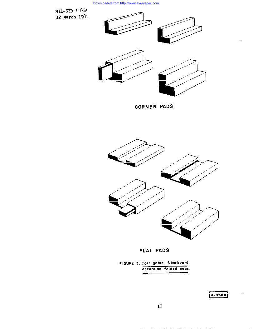
5.3.2.2 Folded pads. Folded pads of corrugated fiberboard as shown in figure
3 may be used for blocking greater loads than are feasible to support with cells
and trayso The pads shall be designed to fit against a flat surface (flat pads)
or along an edge (corner pads). Connecting webs between flat pads shall always
contact the container and not the item. All scores and folds shall be made at
right angles to the flute direction. Flat pads shall be a minimum of ? incheswide. Portions of folded pads in direct contact with the item are bearing
areas. The maximum loads for these bearing areas shall be in accordance with
table II.
TABLE 11. Allowable loads for folded corner andflat pads of corrugated fiberboard.
Maximum allowable loadfor bearing areas lj
Pounds per
Flute design square inch
A-flute (36 ~ 3 corrugations per foot) 2.0
B-flute (50 + 3 corrugations per foot) 3.0
C-flute (42 ~ 3 corrugations per foot) 2.5
1/ Note: The flat crush resistance of the corrugations shall determine the load—that may be carried in flat loading of corrugated fiberboard. This
shall not be construed to mean the bursting strenght of the material.
5.3.2.3 Flat pads. Flat pads of corrguated fiberboard may be used to block
very shallow projections, such as hinges or slight offsets on surfaces; to leveloff projecting screw heads; to fill in the space between ends of inner flaps of
slotted fiberboard boxes; to provide additional protection to contents at top
and bottom of boxes; and to separate items within a container. Allowable loads
shall be in accordance with table 11.
9
Downloaded from http://www.everyspec.com
M~-STD-l186A
12 March I*1
CORNER PADS
/
FLAT PADS
FIGURE 3. Corrugated fibwboard
accordion foldocl pods.
—
lH!!sl -10
Downloaded from http://www.everyspec.com

MIL-STD-1186A
12 March 1981
5.3.2.4 Corner pads. The use of corner pads made of multiple layers of
corrugated fiberboard, as shown in figure 4, shall comply with the load require-
ments of table II. The pads shall provide required clearances (see 5.5) and
support for rectangular shaped items or for an inner box in which items arepacked.
5.3.2.5 Tubes. Fiberboard tubes ~hall be used as blocking when items mounted
on an auxiliary base are packed in fiberboard boxes. The bottom of the tubeshall contact the top of the auxiliary base and the top of the tube shall
contact the top inside surface of the container. The flutes shall be orientedin the top-to-bottom direction of the tube. The weight of the item plus
auxiliary base, in pounds, divided by the perimeter of the tube, in inches,
shall not exceed the appropriate values given in table I for column heights over4 inches.
5.3.2.6 Corner posts. Fiberboard corner posts shall be used to reinforce theshipping container and provide blocking for platfonrmounted equipment. Theflutes shall be oriented in the top-to-bottom direction. The bottom end of the
corner post shall bear on the inner flap of the container or top member of acrate.
5.3.3 Other rigid, low-density materials. Other rigid, low-densitymaterials, such as solid fiberboard conforming to PPP-F-320 and MIL-F-26862, andrigid foam or cellular plastics conforming to MIL-P-19644, MIL-P-24249 orMIL-P-21929, cut, foamed in place, molded, or otherwise formed as required, maybe used for appropriate blocking and bracing applications.
11
nn .-—.. . ---
Downloaded from http://www.everyspec.com

MIL-sm-l186A
M March 1~1
FIGURE 4. MullipiO - Ioyw corrugot. d fiborboord cornor pad8.
El
12
Downloaded from http://www.everyspec.com

MI L-STD-l18~A
12 Harch 1981
5 .3.4 Wood and plywood. Wood or plywood ma~!be used alone or in comb~na-
tion for blocking and Fracing* Wood or p~ywood blockinp an+ bracing members
shall bear against only those parts of the packed item ~~.pabieof withstanding
the applied dynamic forces or shall hear against block.ir.gnads or pressure
strips that adequately distribute these forces. Wood or plywood blocking and
bracing shall be designed to permit easy remo-k’alwithout d.~mage tc the item.Strengths o.f wood J1:J ;lywood members may be calculated !icm info:mat;n gl’lcnin IJSDAAgriculture Handbook No. 72,
5.3.4.: Wood. Wood used for blocking and bracing shall conform to.——.MIL-STD-731* Onc wood member of each size and type used in the blocki~]pand
bracing shall be tested for moisture content. Structural members [th.~~ s~’jject
to critical bending stresses) shall conform to class 1 of ?IIL-STB731. ~lt.,..-
other blocking and bracing members shall conform to class 3. Whenever possible,
WOCKI blocks or braces shall be placed so that the load [s app?ied a~ajnst tb~
end grain of the member. Ends of braces shall be socketca ~r fitted and ~ecl~rei
into appr~~priate notches in load-bearing members.
5.3.4.2 Plywood. Plywood used for blc)ckingand bracir,gshall conf(,r:l1~~NN-P-530, group A, (grade 3-4, type II) or group B, (C-n, interi@r wjt~J~’:t~yi~~glue).
5.3.5 Nails and nailing. Nails shall conform to the requirements c~i‘P( LC;--
cation FF-N-105. All na=s that are not clinched shall be cement ccat(>~.
etched, or mechanically deformed (helically or annularly threaded). Unclinrhet
nails shall be as long as practicable without splitting the material? but n~)tbilwrter t~iarith~~~ times the thf~l.n~~sof the member holding the nailll[a~~~or-..--.-.--ten penny nails and smaller, or not shorter than the thickness of tilesame
member plus 1-1/2 inches for twelve penny nails and larger. Nails loaded in
shear blocking and bracing joints need not be clinched. End grain nailing in
solid wood or edge nailing in polywood shall not be permitted. Nails shall b~
driven through the thinner member into the thicker member wherever possjh!~.
Nails shall not be subject to withdrawal stresses. Nails shall be driver. ‘c’
closer to the end of a piece of lumber than the thickness of the piece and notcloser to its side than one-half ~ts thickness There shall be at least two
nails in each joint. Lateral loading of nails for blocking and bracing sl]~llhein accordance with table 111. Ends of blocks and braces shall not be fastened
to a wood container by end-grain nailing, toe nailing, or similar methods butshall be fastened to a sturdy part of the container or held in place by parallelcleats or other side-grain nailing methods. Blocking and bracing shall be
applied against areas of the item(s) that are of sufficient strength andrigidity to resist damages
5.3.6 Bolt application. Bolts shall be used as fastenings for wood Or plv-
wood blocking and bracing where necessary to facilitate disassembly for removalof container contents. Bolts shall also be used for fastening, blocking and
bracing members that are too thick for proper fastening with nails. Boltholesin wood or pl~ood shall be of the same diameter as the bolts. A flat washer of
proper size shall be used under the nut of each bolt. Bolts, nuts, and washers
shall conform to the requirements of 5.4.1*
, . . . . . . . --- . . i I .,. * .
Downloaded from http://www.everyspec.com
pfIL-s’-f-fj-l~/3(5A
12 March 1981
5.4 Anchoring. .%ncb~~-ingof heavy items shall be accomplished by securing——the item to a base by tension devices, either by bolts through mounting bolt-
holes on the item (baiting town); or by metal strapping, cables, tie rods,chains, wire, or other tension devices attached to, or applied over, the item(tiedown and holadown, : or by both. The same washer requirement as specifiedfor bolts (see 5.4.1) of equal diameter shall apply to tie rods.
‘ABI.E 111. Allou-able loads for unclinchedcement-coated or etchtd common wire nails when used for blocking or bracing-.——
-.-—
1Load, pounds per nail j—. ..—.— .-—
I I ‘Species of }Jood~/ I~d ]6d~8d I
I 10d‘ 12d 16d 20d , 30d..-; ‘od+I
White pine, pundercr 14 17 21 25 26 29 38 j 42 ~ 48p~l?e,q~ruce, ~{nd~~’,1 t
I
grc~u~ ‘ woods
ISoutherriyellow pint, ?1 26 32 39 ~ 40 45 58 65 73Dc,ugla” f~r, westerrt
1<1~(ti,,~ndOtl;{r Kxcu!I1
11 wuo~s. I ‘
oak, maple, L’jrcll,beech, 26 32 Jo 48 49 55 71 80 90ash, and otl~ergroupITI and IV woods.
111!1 I f-—. .- —- . -. 4
1/ Group classification of species not specifically named shall be in accord-ance wjth MIL-STD-731.
j.:4.l Ancl~orbolts. Carriage or step bolts conforming to FF-B-584, type I,class 1, styl~ A or C shall be used. Articles having mounting holes in areast]lat(’anwjthstand rough Ilandling without breakage shall be bolted to either the
base of the container or an auxiliary base. The bolt heads of anchor bolts
(those holding the item to the container base or the auxiliary base) shall be onthe outside of the container when an item is bolted to the base of the container,
otherwise on the underside of the auxiliary base. The heads of all anchor boltsshall.bear against a wide washer conforming to FF-W-92, type A or B, grade 1,c;ass A except that the minimum diameter or minimum size of square shall be asspe~ified in table IV when bolt head is against a wood member. Bolts throughmounting holtholes shall form a snug fit, except that precision holes shall bebushed to prevent damage by anchor bolts. In a crate where the item is bolted
to a skid-type base, the anchor bolts shall pass through the skids or through
load-bearing members that are bolted to the skids. Boltholes in wood shall be
of the same diameter as the bolts. The maximum allowable load for anchor bolts
required and the minimum size of wood-bearing washers shall be as specified intable IV. When the weight of the item exceeds that which can be anchored
adequately using allowable loads shown in table IV and all of the available
mounting holtholes on the item, the excess weight shall be taken care of by tie-
down provisions specified herein. Loosening of the installed nuts shall be
14
. . ● �☛ � .-7 .–:9-— _. _____2L..
Downloaded from http://www.everyspec.com

prevented by either nicking the exposed threads of the bolt; applying paint,
asphaltum or P-1 of HIL-P-116; using lock nuts; or using cotter pins. The
required size and quantity of bolts used as tie rods or for anchoring the endsof the tiedown tension members shall be in accordance with table IV. Lag bolts
(screws) shall not be used for anchoring.
TABLE IV. Maximum allowable loads and minimum sizes of
Wood-bearing washers Maximum allowable load per bolt)iameter Minimum Minimum Items weighing Items weighing Items weighingof diameter size of 200 pounds 200 to 3,000 over 3,000
bolt of round sq~lare and less pounds poundsInch Inch Inch Pounds Pounds Pounds
1/4 1.35 1.00 10 -- .-
5/16 1.75 1.25 30 -- --
3/8 2.10 1.50 50 75 - -
1/2 2.85 2*1O 100 150 3005/8 3.60 2.65 150 225 4503/4 4*7O 3.25 - - 375 750
5.4.2 Metal strapping. Metal strapping used to tiedown an item to the base
or other face of the container or to an auxiliary base shall conform to QQ-S-781
class 1, type I or IV or class 2, type V or VI. Tiedown strapping shall be
securely attached to or looped ov~r the !tem. lt chall ~i anehnwaA ~c ~~c ~Gr,–- ..- - - U..e.tw.eu
tainer or auxiliary base either by looping around a load-bearing member or byutilizing steel slotted anchor plates for flat strapping or drf.vescrews andstaples for round strapping. Padding material or suitable edge protectors, asapplicable, shall be used under the straps to prevent damage to the ~tem. When-
ever possible, all strands holding down an item shall be of approximately the
same length. All tiedown strappings shall be tensioned and sealed securely.Strapping shall be finish B when exposed to the weather and finish A when usedin a protected environment such as a covered crate, etc.
5.4.2.1 Minimum lenght of straps. The minimum total length of strapping of agiven cross section area required for securing a given load can be calculatedfrom the following formulas:
for flat strapping
L=P and
300 Wt
for round strapping
L= 4P300 TT D2
15
Downloaded from http://www.everyspec.com

MIL-STD-1186A
12 March 1981
where P = load
w = width of flat strapping
t = thickness of flat strappingD= diameter of round strappingL = total lenght of strapping required
TT = 3.14
The calculated length of strapping required does not include tl)atportion of
material used to make secure fastenings at the ends of each strand but is thesum of and does include all lengths of material between such fastenings.Overall lengths of each strand shall be adequate to permit fastening as
specified in 5.4.2. The load capacity of steel strapping is based on available
energy of 8640 inch-pounds per cubic inch of strap in tension at a drop heightof 30 inches. The above formulas are applied on the basis of 300 pounds of load
per cubic inch of strap in tension.
5.5 Clearance. When an item is blocked, braced, anchored, or tiedown to theinside of one face of a container or to an auxiliary base which, in turn, is sosecured, a clearance of not less than 1 inch shall be provided between the itemand all members of the remaining faces of the container. A minimum clearance of
2 inches shall be provided around fragile parts of the item that might bedamaged due to slight distortion of the container. A minimum 2-inch clearance
shall also be provided between ~tems within floating bag barriers and ajacentmembers of the container.
5.6 Vacerprooiing . ExcepL as ~L~)-Vide~ }lei-eIi_l,‘--L--WCLLIYL ‘~)~fi~f..- - - -Iiriers,wLcApb,
shrouds, or other suitable means shall be provided in shipping containers as
necessary to prevent the entry of water. Such protection, however, is not
necessary when items, dunnage, exterior cushioning, and interior packages are
water-resistant or otherwise water-proofed. Water-proof liners, wraps, shrouds,
or other similar protection shall also be required where such protection againstthe entry of dust, dirt, and other foreign matter is necessary. All seams shallbe completely and continuously sealed to provide water resistance equivalent tothat provided by the barrier material itself. Barrier materials and sealants
constructed with asphaltum shall not be used in the presence of moth-proofingchemcials such as paradichlorobenzene and napthalene. Barrier materials and
sealants constructed with asphaltum shall not be used to protect items subjectto stain or other damage by asphalt, unless such items are initially protected
to exclude asphaltm All sharp points of contact between an item and barrier
material shall be cushioned to prevent rupture or chafing of the barrier.
5.6.1 Liners and linings (see 30.2).
—
5.6.1.1 Case liners. Case liners shall be fabricated and closed in accordance
with MI1-L-10547, type and grade as applicable for specific requirements.
Downloaded from http://www.everyspec.com
!41L-STD-1186AlZ March 1981
5.6.1.2 Linings for drums, kegs, barrels, and bags. Linings shall be pro-
vided for drums, kegs, barrels, or bags when their contents require protec-tion not otherwise provided by the containers against sifting, contamination
or free water. The lining material shall conform to specification PPP-B-1055or MIL-F-22191. Fabrication and closure seams shall be heat-sealed or sealedwith adhesive conforming to .MMM-A-260 as applicable.
5.6.2 Water-proof and water-vaporproof wraps. Water-proof and water-vapor-proof wraps shall be fabricated and sealed in accordance with MIL-L-10547.
5.6.2.1 Unsealed water-proof wraps. Unsealed water-proof wraps shall beapplied to shed water while permitting breathing and circulation of air.
5.6.3 Shrouds. Shrouds shall be fabricated from material conforming tospecification L-P-378, or PPP-B-1055 of a class as specified for shrouds. Seamsshall be made using adhesive conforming to MMM-A-260 or by heat sealing, asapplicable. There shall be no constricting external ties binding the shroud toupper parts of the item, but the sides and ends of the shroud shall hang or bedrawn down as straight as is feasible and secured to the base of the item or
container. The fastening at bottom shall prevent tearing or loosening of theshroud by storms. There shall be no snagging of the applied shroud that willform catchment areas to trap and hold water. Bottom openings to permitbreathing and drainage shall be provided.
Custodian:Amy - ~lJ.u-Navy - SAAir Force - 69
Review activities:
Army - MI, MT, SM, EANavy - EC, YDAir Force - 99DLA - GS
Preparing activity:Amy - -HE
Project: PACK-0507
17
Downloaded from http://www.everyspec.com

MIL-S-D-1186A
APPENDIX A
12 March 1981
APPEhLDIXA
TEST METHODS
100 GENERAL
10.1 Scope. This appendix covers requirements for the testing of packsprepared for shipment. While this appendix does not cover the complete realm cf
tests available to assure pack integrity, it does include the more commonly used
test procedures for assuring the packs capability to withstand rough handlinge
~(), APPLICABLE DOCLMXTS
20.1 Issues of documents. The following document, of the issue in effect on
date of invitation for bids or request for proposal forms a part of this specifi-cation to the extent specified herein:
FEI)-STD-101 - Preservation, Packaging, and PackingMaterials.
30. REQUIREMENTS
30.1 Failure criteria. At the conclusion of the tests or at any time during
the tests as deemed necessary by the Gover~ent~ the pack shall be examinedo
Any shifting of contents, loosening or breaking of boldowns, ties, stays,
biocking or bracing, allyvisible d~~ag~ to tbLe~O~teflt~,or anY othercljscernihle damage which would render the pack useless for its intended use
shall constitute failure of this test.
30.2 Drop tests. The free fall drop test shall only apply to containers
having no one dimension over 60 inches and a gross weight of 200 pounds orless. The cornerwi se-drop test and edgewise-drop test shall only apply to
larger containers over too pounds gross Weigtlt or with any dimension exceeding
60 inches.
30.2.1 Free fall drop test. The container shall be drop tested in accordancewith FED-STE101, method 5007, procedure B and procedure E.
30.2.2 Cornerwise-drop test. ‘he container shall be tested as specified in
FED-STBIOI-, method 5005.
30.2.3 Edgewise-drop test. The container shall be tested in accordance withFED-STD-101, method 5008. ‘-
30.3 Vibration test. Th~ container shall be vibration tested in accordancewith FED-STD-101, method 5019 or 5020 as specified.
30.4 Impact tests.
3G.4.1 Pendulum-impact test. The container shall be tested in accordancewith FED-STD-101, method 50120
—
18
Downloaded from http://www.everyspec.com
MIL-STP1186A
APPENDIX A12 March 1981
30.4.2 Incline-impact test. The container shall be tested in accordance withFED-STD-101, method 5023.
30.4.3 Rail-impact test. The packed item, in its normal shipping configura-tion, shall be adequately blocked and secured to the floor of the test rail carto prevent any longitudinal, vertical or lateral movement. Loading and tiedo~’nsshall be in accordance with applicable practices of the Association of American
Railroads. The test car shall be impacted into two to five buffer cars. Thebuffer cars shall be located on a level section of track with the air and hand
brakes set and draft gear extended. The total weight of the buffer cars shallbe 250,000 pounds minimum. All cars shall be equipped with standard draft gear
and conventional under frame. Three impacts shall take place at 4, 6, and 8miles per hour (MPH) in one direction and one impact at 8 mph in the opposite
direction. The velocities given are minimum values and should not be exceeded
by more than is necessary to insure that these values are met.
Downloaded from http://www.everyspec.com

MIL-STD-1186A
APPENDIX B1~ March 1981
APPENDIX B
QUALITY ASSUWNCE
10• SCOPE
10.1 Scope. This appendix established the inspection methods and proceduresnecessary to achieve the desired quality assurance. This appendix is a
mandatory part of this standard.
20• APPLICABLE DOCUMENTS
20.1 Issues of documents. The following documents, of the issue in effect on
date of invitation for bids or request for proposal forms a part of this specifi-cation to the extent specified herein:
MTL-S-D-105 - Sz~mplingProcedure and Tables for Inspectionby Attributes.
30• QUALITY ASSURANCE PROVISIONS
30.1 Responsibility for inspection. Lnless otherwise specified in the
contract or purchase order, the contractor is responsible for the performance of
all inspection requirements specified herein. The contractor may utilize his
own or any other facilities suitable for the performance of the inspectionrpq~~irements specified herein, unless disapproved by the Government. The
Government reserves the right to perform any of the inspections set forth in the
standard where such inspection are deemed necessary to assure supplies andservices conform to prescribed requirements.
30.2 !’sterial inspection. The contractor is responsible for insuring that
materials used are manufactured, examined, and tested in accordance w~threferenced documents or as specified herein.
40• QLIALITYCONFORMANCE INSPECTION
40.1 Unit of product. For the purpose of inspection, a completed pack
prepared for shipment shall be considered a unit of product.
4c.2 Inspection lot. When an inspection lot ~s required for the specific
inspection plan being used, the inspection lot shall consist of identical items
on the same contract or order prepared for shipment in the same manner andpresented for inspection at the same time and place.
40.3 Sampling. Samples for inspection shall be selected at random from each
inspection lot in accordance with procedures prescribed in MIL-STD-105.
2c)
Downloaded from http://www.everyspec.com
MIL-STD-1186A
APPENDIX B
12 March 1981
40.4 Examination. Samples selected in accordance with 40.3 shall be examined
for the defects lis-tcdbelowo These defects shall form a part of the quality
assurance provisions of the procuring documento The Acceptance Quality Level
(AQL) shall be ~.O percent defective unless otherwise specified in the procuring
document.
1(1 ●
J@~o
1(.)?,
104.105.
106.
107.
108.1090
110.111.112.113.
114.
?Iaterials not as specified.Cc>ntents not arranged to pro~’ide smallest practical cubage.rl~.q~sen;~’~fiparts not matchmarked a“ specified.
Arrangement of contents in container not as specified.:!~tcria~s in contact with surfaces susceptible to damage from
corrosion or deterioration not as specified.
Protection against abrasion for highly finished or easily marred
surfaces not provided as specified.Strippable coatings and barrier wraps not protected at points of
contact with blocking, bracing and container projections.Contents of shipping containers not immobilized as specified.Allowable loads imposed on fiberboard forms exceeds the valuesspecified herein.Nails and nailing not as specified.
Applicat~on of bolts not as specified.Application of strapping not as specified.h!inimum rlearance between contents and container faces not as
specifiedWater-proofing of containers not as specified.
21
u I--- ___
Downloaded from http://www.everyspec.com

MIL-STD-118GA
APPENDIX C
12 March 1981
APPENDIX C
NOTES
10. SCOPE
10.1 scope. W.is appendix .s ‘ntended only for information and is not a man-
datory part of this standard.
2G* APPLICABLE DOCUMENTS
20.1 issues of documents. The following documents of the issue in effect ondate of invitation for bids or request for proposal forms a part of this specifi-cation to the extent specified herein:
MIL-HDBK-304 - Package Cushioning Design.TM 38-230-1 - Preservation and Packaging.
(DSAM 4145.2, NAVSUP put)502, AFP 71-15,MC0 4030.31A)‘I?l38-203-2 - Packaging.
(NAI’SLIPP{lb503, AFP 71-16, MCO 4030.21B)
30. NOTES
30.1 Factors influencing cushioning selection and use. Shock resulting fromrough handling and shipping container is the usual cause of mechanical damage ofthe contents. The purpose of cushioning is to reduce the intensity of the shock
reaching the packed item to a level which the item can safely withstand.Factors influencing cushion design are the fragility and weight of the item, the
load-bearing area of the cushion, the dynamic force-deformation characteristic
of the cl’shionjrlgmaterial, and the height of drop for which protection is
desired, Among these, the fragility and weight of the item are fixed values for
any particular ~tem. The load-bearing area of the cushion can be altered by
design or by packing the item ~n an inner container, if desired. Cushioning
design curves relating fragility value of item to weight per unit of bearing
area (or compressive stress due to the weight of the item) are available fromcushioning material manufacturers. MIL-HDBK-304 provides design procedures for
the solution of cushioning problems. There are also a number of commercial
textbooks available relating to cushion design.
30.2 Disadvantages of case liners made f~Gm barrier materials other thanwater-vaporproof materials. Experience has shown that under some conditions,especially when contents do not fill the case liner completely, case liners domore harm than good by trapping and holding water rather than preventing itsentry. It is not essential that there be openings in a sealed case liner forthis to happen. If the case liner material I!aslow resistance to water-vaportransfer (a common occurrence) water can enter in the form of vapor and condense
22
Downloaded from http://www.everyspec.com

MIL-STD-1186A
APPENDIX C12 March 1981
on contents within the liner. That this can be largely a one-way process has
been proven when, at the end of an extended outdoor exposure period, sealed case
liners have been opened and found partially filled with liquid water. Whenpacked items need protection against water, it is preferable to incorporate theprotection in the individual unit packages in lieu of case liners.
30.3. Supplemental information. Supplemental information on packaging may befound in the Technical Manuals on Preservation, Packaging, and Packing ofMilitary Su/~ljes and Equipment: Volume 1, Preservatir~n and Packaging (ThlJ3--230-1, DSAM 4145.2, NAVSUP PUB 502, AFP 71-15, MCO 4030.31A) and Volume II,
Packing (TM 38-230-2, DSAM 4145.2, NAVSUP PUB 503, AFP 7i-16, MCO 4030.21B).
23
Downloaded from http://www.everyspec.com

MIL-STD-1186AIZ March 1981
INDEX
paragraph
Abrasion protection
Anchor boltsAnchoring
Application
Airangcrnent of con+ ?;+.sBlocking and bracingBolts, anchorBolts, application
Clearance requirementsCorrosion
CushioningDangerous articlesDefinitionsDisassembly
Documents, applicable
Dusting
Fiberboard formsFlotation
Linings
MatchmakingMoisture resistanceNailsNotesPerformancep~:,~ood
Qllality assuranceScopeShroudsStrappingSuspensionTest ❑ethods
WaterproofingWood
Wraps
24
5.2.25.3.15.4.15,4
1.25.1
5.35.4.15.3.6
5.55.1.5
5.3*1
5.24.2
35.1.12
Appendix A-20Appendix B-205.2.55.3.25.2.15.6.1CllJ.A*l.I
5.2.45.3.5Appendix C4.45.3.4Appendix B
1.15.6.35.4.?
5.?.1Appendix A
5.65.3.45.3.4.15.6.?
%-=-e-+ -*--.----=------u--._-------_--------------------+--s . . - —-.—.
Downloaded from http://www.everyspec.com

DEPARTMENT OF THE ARMY
OFFICIAL BUSINESSPENALTY FOR PRIVATE USE S~O
111111L1NO POSTAGE
NECESSARY
IF MAILED
IN THE
uNITED STATES
BUSINESS REPLY CARDFIRST CLASS PERMIT NO. 12062 WASHINGTON D C
.
POHAGE WILL BE PAID BY THE DEPARTMENT OF THE ARMY
CommanderUSA ?lobility Equipment R&D CommandATTN : DRDME-DSFt. Belvoir, VA 22060
Downloaded from http://www.everyspec.com

STANDARDIZATION DOCUMENT IMPROVEMENT PROPOSAL I
INSTRUCTIONS Thisformisprovidedtosohcitbeneficdcornmenuwhichmay improvethisdocumentandenhance its use. DoD contractors, government activities,manufacture,vendors, or other prospective users ofthe document are invited to submit comments to the government Fold on lines on reveme side, stapleIncorner,andsendtopreparingactiwty.Attachanypertinentdatawhichmay be of use in improving this document Ifthere are additional papers, attach to form and place both m ●n envelope addressedtopreparingsctivit~.Aresponse will be provided to the submitter, when name and address M provided, within 30 days indicating thatthe1426wagrece]ved and when any appropriate action on it will be completed.NOTE: This form shall not be used to submit requests for waivers, deviations or clarification of apecificatlonrequirements on current contracts. Comments submitted on th16form do not constitute or imply ●uthorlzat]onto ‘waive any portion of the referenced documents) or to amend contractual requirements.
>OCUMENT IDENTIFIER (NUmbcrl AND TITLE }!lL-STD-l 186A Cushioning, Anchoring, Bracing,Blocking and Waterproofing; with Appropriate Test MethodsQAME OF ORGANIZATION AND ADDRESS OF SUBMITTER
(_) VENDOR ~ USER n MANUFACTURER
1 0 HAS ANY PART OF THE DOCUMENT CREATED PROBLEMS OR REQuIRED INTERPRETATION IN PROCUREMENT
JSE? ~ IS ANY PART OF IT TOO RIGID, RESTRICTlvE LOOSE OR AM BIG UOUS7 PLEASE EXPLAIN BELOW
A. GIVE PARAGRAPH NUMBER AND WORDING
B. RECOMMENDED WORDING CHANGE
C. REASON FOR RECOMMENDED CHANGE(S)
2 REMARKS
;uEt MITl% () BY (R[ntfd or t>ped name and addw~a – OPt’IOUd’ TELEPHONE NO
DATE
DD ‘mM1426 EDITION OF I JAN 72 WILL BE USE OUN~IL EXHAUSTED
1 OCT 76
Downloaded from http://www.everyspec.com