Embed Size (px)
Citation preview

October 24, 2005
5F, M&S Plaza, 141-2, Songpa-dong, Songpa-gu, Seoul, Korea 138-170
Tel: +82-2-417-3450 Fax: +82-2-417-3490 http://www.pentamicro.com
Data Sheet – Version 2.0
AATT22004411 Multi-channel MPEG-4 CODEC
AATT22004422 2-channel MPEG-4 CODEC
AATT22004433 Multi-channel MPEG-4 Encoder

CONFI
DEN
TIAL
AT2041/AT2042/AT2043 Multi-channel MPEG-4 CODEC
October 24, 2005 Version 2.0 2
We, Pentamicro Inc., reserve the right to change any products described herein at any time and
without notice. We assume no responsibility or liability arising from the use of the product
described herein, except as expressly agreed to in writing by us. The use and purchase of the
product does not convey a license under any patent rights, copyrights, trademark rights, or any other
intellectual property rights of us.
Pentamicro Inc.
5F, M&S Plaza, 141-2, Songpa-dong, Songpa-gu, Seoul, Korea 138-170
TEL +82-2-417-3450 FAX +82-2-417-3490 E-mail [email protected] Web. www.pentamicro.com

CONFI
DEN
TIAL
AT2041/AT2042/AT2043 Multi-channel MPEG-4 CODEC
October 24, 2005 Version 2.0 3
Revision History
Revision No. Date Modification List
Version 0.4 03/15/2004 First release of AT2041/AT2042/AT2043 datasheet
Version 0.5 03/19/2004 7.4 SDRAM Signal Connection
Version 0.6 04/22/2004 Add Audio to 1.1 Key Features
Version 0.7 05/24/2004 Add 10. Host Interface Parameters & Messages
Version 1.0 07/10/2004 Add 11. Function Details
Version 1.1 09/20/2004 -. Add 6.3. Master / Slave Mode. -. Modify Table 9. SDRAM Size for Codec (AT2041, AT2042), Mbit and Table 10. SDRAM Size for Encoder (AT2043), Mbit.. -. Modify figures of 8.3 Timing diagram. -. Modify contents of 10. Host Interface Parameters & Messages. -. Modify contents of 11. Function Details. -. Add 14.2. Re-flow Profile Guideline.
Version 1.2 01/07/2005 -. Add CMOS interface to 1.1. Key Features. -. Modify contents of 6. Audio Interface. -. Add a section, 9.2. H/W Reset.
-. Modify contents of 10. Host Interface Parameters & Messages. +. Channel ID interface parameters +. Trans-coding mode +. Audio parameters +. Trick mode parameters +. Graphic OSD parameters
-. Add a section, 12.1.4. Power Consumption.
Version 1.3 02/22/2005 -. Minor modification of 2.4. Video Post-processing
-. Modify contents of 10. Host Interface Parameters & Messages. +. Encoder acknowledge mode parameter +. Global status parameter +. Display mode parameters +. Output time stamp parameters +. Closed GOP type 2
-. Add BGA package information in 13. Pin Assignments and 14. Package.
Version 2.0 10/24/2005 -. Add 15. Rx Parameters in Detail. -. Add 16. Tx Parameters in Detail -. Modify contents of 10. Host Interface Parameters & Messages.
* Blue text indicates that the contents is changed or added from one of version 1.1. * Red text indicates Rx parameters that is changed or added from one of version 1.3.
CONFI
DEN
TIAL
AT2041/AT2042/AT2043 Multi-channel MPEG-4 CODEC
October 24, 2005 Version 2.0 4
Contents
1. Overview ............................................................................................... 13
1.1. Key Features ....................................................................................15
1.2. Specifications...................................................................................18
1.3. Applications.....................................................................................19
2. Description of Functions ............................................................................ 20
2.1. Multi-standard Video Encoding/Decoding.................................................20
2.2. Multi-channel Video Encoding/Decoding ..................................................20
2.3. Video Pre-processing .........................................................................22
2.4. Video Post-processing........................................................................23
2.5. Video Coding Options .........................................................................26
2.6. Internal Watermarker ..........................................................................28
2.7. Real-time Trans-coding ......................................................................29
2.8. Motion Detection ...............................................................................29
2.9. Multiplex & De-multiplex......................................................................29
3. Description of Signals ............................................................................... 31
3.1. Video Input Interface ..........................................................................31
3.2. Video Output Interface ........................................................................31
3.3. Audio Interface .................................................................................32
3.4. SDRAM Interface ...............................................................................32
3.5. Host Interface...................................................................................33
3.6. GIO ...............................................................................................34
3.7. Miscellaneous...................................................................................34
3.8. Power & Ground................................................................................35
4. Video Input Interface................................................................................. 37
4.1. Video Input Format ............................................................................37
4.2. VBI Data Extraction ............................................................................42
5. Video Output Interface............................................................................... 43

CONFI
DEN
TIAL
AT2041/AT2042/AT2043 Multi-channel MPEG-4 CODEC
October 24, 2005 Version 2.0 5
5.1. Video Format ...................................................................................44
5.2. VBI Insertion.....................................................................................46
6. Audio Interface........................................................................................ 47
6.1. PCM Mode ......................................................................................47
6.2. I2S , Left Justified Mode......................................................................49
6.3. Master / Slave Mode ..........................................................................51
7. External SDRAM Interface........................................................................... 52
7.1. SDRAM Requirement ..........................................................................52
7.2. SDRAM Operation Mode ......................................................................52
7.3. SDRAM Size.....................................................................................52
7.4. SDRAM Signal Connection ...................................................................53
8. Host Interface......................................................................................... 56
8.1. Host Interface Unit Architecture .............................................................56
8.2. Register and FIFO Access....................................................................57
8.3. Timing diagram.................................................................................59
8.4. Signal Mapping .................................................................................64
9. Miscellaneous Signals ............................................................................... 65
9.1. System Clock (SYSCLK) ......................................................................65
9.2. H/W Reset.......................................................................................66
9.3. GIO ...............................................................................................66
9.4. Boundary Scan .................................................................................68
9.5. MC (Multi-Channel Select) ...................................................................71
10. Host Interface Parameters & Messages .......................................................... 72
10.1. Rx Parameter Interface Protocol ..........................................................72
10.2. Tx Message Interface Protocol ............................................................73
10.3. Start-up Sequence ..........................................................................75
10.4. Encoding Sequence.........................................................................78
10.5. Decoding Sequence.........................................................................79
10.6. Rx Parameter Table .........................................................................80

CONFI
DEN
TIAL
AT2041/AT2042/AT2043 Multi-channel MPEG-4 CODEC
October 24, 2005 Version 2.0 6
10.7. Tx Message Table ......................................................................... 106
11. Function Details .................................................................................... 110
11.1. Video Input Interface ...................................................................... 110
11.2. Video Output Interface.................................................................... 111
11.3. VBI (Vertical Blanking Interval) .......................................................... 116
11.4. Channel ID Interface ...................................................................... 118
11.5. Multi-Channel Encoding.................................................................. 120
11.6. Multi-Channel Display .................................................................... 121
11.7. Motion Detection........................................................................... 122
11.8. Rate Control ................................................................................ 123
11.9. Frame Rate Control ....................................................................... 124
11.10. GOP Structure .............................................................................. 124
11.11. Encoder Output Data Size Control...................................................... 125
11.12. Decoder Input Data Size Control........................................................ 125
12. Electrical Specifications ........................................................................... 127
12.1. Electrical specification.................................................................... 127
12.2. Timing Parameter for Video Input Interface ........................................... 131
12.3. Timing Parameter for Video Output Interface......................................... 132
12.4. Timing Parameter for Audio Interface.................................................. 133
12.5. Timing Parameter for SDRAM Interface ............................................... 135
12.6. Timing Parameter for Host Interface ................................................... 136
12.7. Timing Parameter for SPI ROM Interface .............................................. 137
13. Pin Assignments.................................................................................... 138
14. Package Information............................................................................... 146
14.1. Package Dimensions ..................................................................... 146
14.2. Re-flow Profile Guideline................................................................. 148
14.3. Pb-free Notification ....................................................................... 148
15. Rx Parameters in Detail............................................................................ 149
15.1. Global Parameters (GID=0x0, CID=0x0)............................................... 149

CONFI
DEN
TIAL
AT2041/AT2042/AT2043 Multi-channel MPEG-4 CODEC
October 24, 2005 Version 2.0 7
15.2. Encoder System Parameters (GID=0x1, CID=0x0)................................... 153
15.3. Encoder Video Parameters (GID=0x4, CID=0x0)..................................... 155
15.4. Encoder Video Channel Parameters (GID=0x5, CID=Channel ID)................. 161
15.5. Encoder Audio Parameters (GID=0x6, CID=0) ....................................... 169
15.6. Encoder Audio Channel Parameters (GID=0x7, PID=Ch_ID) ....................... 170
15.7. Decoder System Parameters (GID=0x2, CID=0x0) .................................. 171
15.8. Decoder Video Parameters (GID=0x8, CID=0x0)..................................... 176
15.9. Decoder Video Channel Parameters (GID=0x9, CID=Channel ID) ................ 181
15.10. Decoder Audio Parameters (GID=0xA, CID=0x0) .................................... 185
15.11. OSD Parameters (GID=0x3).............................................................. 187
16. Tx Parameters in Detail............................................................................ 194
16.1. Global Messages (GID=0x0, CID=0x0)................................................. 194
16.2. Encoder System Messages (GID=0x1, CID=0x0) .................................... 194
16.3. Decoder System Messages (GID=0x2, CID=0x0) .................................... 195

CONFI
DEN
TIAL
AT2041/AT2042/AT2043 Multi-channel MPEG-4 CODEC
October 24, 2005 Version 2.0 8
List of Figures
Figure 1. AT2041/AT2042 Block Diagram............................................................. 14
Figure 2. AT2043 Block Diagram ....................................................................... 14
Figure 3. Examples of Multi-channel Display ......................................................... 23
Figure 4. Live & Decoded Video Display............................................................... 24
Figure 5. Display Layer ................................................................................... 25
Figure 6. Watermark Processing ........................................................................ 28
Figure 7. Video Decoder Signal Connection for External Sync Mode ............................. 37
Figure 8. Video Decoder Signal Connection for Embedded Sync Mode ......................... 38
Figure 9. External Sync Format for NTSC ............................................................. 39
Figure 10. External Sync Format for PAL .............................................................. 39
Figure 11. Embedded Sync Format for PAL(top) and NTSC(bottom) ............................ 41
Figure 12. Signal Connection for Video Encoder Interface ......................................... 43
Figure 13. SAV/EAV for ITU-R BT.656 Embedded Sync ........................................... 44
Figure 14. Connection for External Sync Master Mode.............................................. 45
Figure 15. Connection for External Sync Slave Mode ............................................... 45
Figure 16. PCM Mode Timing Diagram ................................................................ 47
Figure 17. I2S Mode Timing Diagram .................................................................. 49
Figure 18. Left Justified Mode Timing Diagram ...................................................... 49
Figure 19. SDRAM Signal Connection (32-bit SDRAM x 1) ........................................ 54
Figure 20. SDRAM Signal Connection (16-bit SDRAM x 2) ........................................ 54
Figure 21. Host Interface Block Diagram.............................................................. 56
Figure 22. Single Read Timing for MPC-850 ......................................................... 60
Figure 23. Single Read Timing for IBM PowerPC..................................................... 60
Figure 24. Single Write Timing for MPC-850.......................................................... 61
Figure 25. Single Write Timing for IBM PowerPC..................................................... 61
Figure 26. Burst Read Timing for MPC-850 .......................................................... 62
Figure 27. Burst Read Timing for IBM PowerPC...................................................... 62
Figure 28. Burst Write Timing for MPC-850........................................................... 63
Figure 29. Burst Write Timing for IBM PowerPC ...................................................... 63

CONFI
DEN
TIAL
AT2041/AT2042/AT2043 Multi-channel MPEG-4 CODEC
October 24, 2005 Version 2.0 9
Figure 30. Circuit Diagram of Crystal Oscillation Circuit / LSI External Clock Signals ......... 65
Figure 31. nRESET Timing ............................................................................... 66
Figure 32. SPI Serial ROM Signal Connection ........................................................ 67
Figure 33. TAP Multiplexing .............................................................................. 68
Figure 34. JTAG Signal Connection (20-Pin Connector) ........................................... 69
Figure 35. JTAG Signal Connection for Unused Case............................................... 69
Figure 36. RxID Format ................................................................................... 72
Figure 37. RxData Format................................................................................ 72
Figure 38. TxID Format ................................................................................... 74
Figure 39. TxData Foramt ................................................................................ 74
Figure 40. Start-Up sequence........................................................................... 76
Figure 41. Encoding Sequence.......................................................................... 78
Figure 42. Decoding Sequence ......................................................................... 79
Figure 43. Setting of Vertical Offset ...................................................................110
Figure 44. First Field Decision Parameter ............................................................111
Figure 45. Polarity of Sync Signals ....................................................................111
Figure 46. H_VALID Timing .............................................................................112
Figure 47. Vertical Offset for NTSC....................................................................113
Figure 48. Vertical Offset for PAL ......................................................................113
Figure 49. First Field Decision Parameter ............................................................114
Figure 50. Setting of HSYNCOUT ......................................................................114
Figure 51. VSYNCOUT Control – Line Position .....................................................115
Figure 52. VSYNCOUT Control – Pixel Position.....................................................115
Figure 53. Polarity of Video Output Sync .............................................................116
Figure 54. VBI Extraction – Line Position ............................................................117
Figure 55. VBI Extraction – Pixel Position ...........................................................117
Figure 56. VBI Insertion – Pixel Position .............................................................118
Figure 57. Multi-Channel Encoding....................................................................120
Figure 58. Multi-Channel Display ......................................................................121
Figure 59. Motion Detection Area Setting ............................................................123
Figure 60. Frame Rate Control .........................................................................124

CONFI
DEN
TIAL
AT2041/AT2042/AT2043 Multi-channel MPEG-4 CODEC
October 24, 2005 Version 2.0 10
Figure 61. 3.3V I/O L, M Type V-I Characteristics ..................................................129
Figure 62. 3.3V I/O H, V Type V-I Characteristics ..................................................129
Figure 63. Video Input Interface Timing...............................................................131
Figure 64. Video Output Interface Timing ............................................................132
Figure 65. Audio Input Interface Timing ..............................................................133
Figure 66. Audio Output Interface Timing ............................................................134
Figure 67. SDRAM Interface Timing ...................................................................135
Figure 68. Host Interface Timing.......................................................................136
Figure 69. SPI ROM Interface Timing..................................................................137
Figure 70. AT2041 Pin Assignments (top view) .....................................................138
Figure 71. AT2042 Pin Assignments (top view) .....................................................139
Figure 72. AT2043 Pin Assignments (top view) .....................................................140
Figure 73. AT2042P Pin Assignments (BGA package - top view) ...............................141
Figure 74. AT2042P A1 Position and Marking Direction (top view) ..............................141
CONFI
DEN
TIAL
AT2041/AT2042/AT2043 Multi-channel MPEG-4 CODEC
October 24, 2005 Version 2.0 11
List of Tables
Table 1. Feature Table of AT2041/AT2042/AT2043................................................. 18
Table 2. Maximum Frame Rate ......................................................................... 21
Table 3. Video Timing Reference Codes .............................................................. 40
Table 4. SAV and EAV Table ............................................................................ 44
Table 5. Frame Sync Width in PCM Mode - Encoding.............................................. 48
Table 6. Frame Sync Width in PCM mode - Decoding ............................................. 48
Table 7. Frame Sync Width in I2S/Left-Justified mode - Encoding .............................. 50
Table 8. Frame Sync Width in I2S/Left-Justified mode - Decoding.............................. 50
Table 9. SDRAM Size for Codec (AT2041, AT2042), Mbit ......................................... 53
Table 10. SDRAM Size for Encoder (AT2043), Mbit ................................................. 53
Table 11. Host Interface Address Map................................................................. 57
Table 12. Status Register................................................................................. 57
Table 13. Command Register ........................................................................... 58
Table 14. CPU mode of The AT204x................................................................... 64
Table 15. IDCODE for Boundary SCAN ................................................................ 70
Table 16. Operation Code for Boundary Scan........................................................ 70
Table 17. The relationship between display mode and zoom/scale-down factor.............100
Table 18. Maximum Ratings ............................................................................127
Table 19. Recommended Operating Condition......................................................128
Table 20. DC Characteristics ...........................................................................128
Table 21. Output Pin Type ..............................................................................130
Table 22. Power Consumption .........................................................................130
Table 23. Video Input Interface Timing Table........................................................131
Table 24. Video Output Interface Timing Table......................................................132
Table 25. Audio Input Interface Timing Table........................................................133
Table 26. Audio Output Interface Timing Table .....................................................134
Table 27. SDRAM Interface Timing Table ............................................................135
Table 28. Host Interface Timing Table ................................................................136
Table 29. SPI ROM Interface Timing Table...........................................................137

CONFI
DEN
TIAL
AT2041/AT2042/AT2043 Multi-channel MPEG-4 CODEC
October 24, 2005 Version 2.0 12
Table 30. AT204x Pin-outs .............................................................................142
Table 31. AT2042P Pinouts (BGA package) .........................................................144

CONFI
DEN
TIAL
AT2041/AT2042/AT2043 Multi-channel MPEG-4 CODEC
October 24, 2005 Version 2.0 13
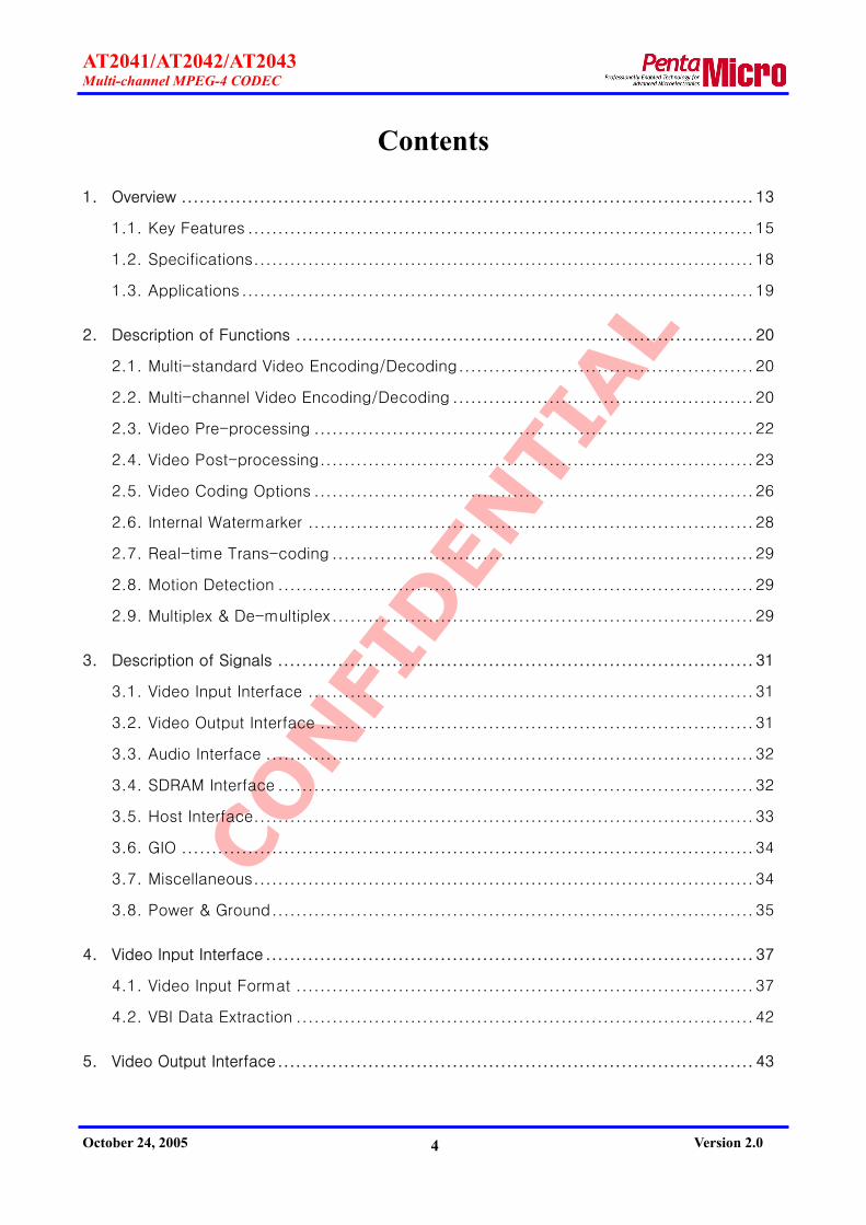
1. Overview The AT2041/AT2042/AT2043 series (AT204x) is a multi-channel A/V CODEC chip that
compresses the video into MPEG-1, MPEG-2, MPEG-4, H.263, JPEG and Motion-JPEG format as well
as the audio into ADPCM and MPEG-1 layer-II audio standard. The chip multiplexes audio and
video streams and outputs them as MPEG-1 system streams, MPEG-2 program streams and MPEG-
2 transport streams. It is applicable for network and media file format – AVI file format and MPEG-
4 file format.
The AT2041 is a multi-channel A/V CODEC chip, the AT2042 is a 2-channel A/V CODEC chip,
and the AT2043 is a multi-channel A/V encoder chip. The AT2041 enables encoding and decoding
simultaneously up to 720pixels × 480lines @29.97fps for NTSC and up to 720pixels × 576lines
@25fps for PAL and enables video encoding and decoding up to 16 channels simultaneously as
well. For multi-channel video encoding, the AT204x supports not only temporal domain division
encoding but also spatial domain division encoding method. The maximum frame rate of the chip
is 30(25) fps for full-D1 video, 120(100) fps for CIF video, and 480(400) fps for QCIF video.
For multi-channel video decoding, the AT2041 and AT2042 output scaled video for 1 ~ 16
divided pictures and support x2 zoom, PIP(picture-in-picture) and graphic OSD(on-screen-display).
The AT204x encodes audio as ADPCM up to 16 channels and decodes single channel at the same
time.
In addition, the AT204x provides motion detection, trans-coding and watermarking for the
recording system applications such as DVR and PVR. The motion detection is designed to meet the
low-illuminated conditions appropriately, and users can control the detection area and sensitivity
for each channel independently. For the trans-coding, the chip allows flexibility for real-time trans-
coding in video standard, video resolution, frame rate and bit rate.

CONFI
DEN
TIAL
AT2041/AT2042/AT2043 Multi-channel MPEG-4 CODEC
October 24, 2005 Version 2.0 14
RISC Core(ARM946E)RISC Core(ARM946E)
SpeechCodec
SpeechCodec
VideoOutput
Interface
VideoOutput
Interface
SDRAMControllerSDRAM
Controller
DigitalVideo
HostInterface
RISC Core(ARM946E)RISC Core(ARM946E)
SpeechCodecAudioCodec
VideoInput
Interface
SystemMux/Demu
x
VideoOutput
Interface
VideoOutput
InterfaceSDRAM
ControllerSDRAM
Controller
MotionEstimation/Prediction
VLC/VLDDCT/QIQ/IDCT
DigitalVideo
SDRAM Digital Audio
HostCPU
RISC Core(ARM946E)RISC Core(ARM946E)
SpeechCodec
SpeechCodec
VideoOutput
Interface
VideoOutput
Interface
SDRAMControllerSDRAM
Controller
DigitalVideo
HostInterface
RISC Core(ARM946E)RISC Core(ARM946E)
SpeechCodecAudioCodec
VideoInput
Interface
SystemMux/Demu
x
VideoOutput
Interface
VideoOutput
InterfaceSDRAM
ControllerSDRAM
Controller
MotionEstimation/Prediction
VLC/VLDDCT/QIQ/IDCT
DigitalVideo
SDRAM Digital Audio
HostCPU
Figure 1. AT2041/AT2042 Block Diagram
RISC Core(ARM946E)RISC Core(ARM946E)
SpeechCodec
SpeechCodec
SDRAMControllerSDRAM
Controller
DigitalVideo
HostInterface
RISC Core(ARM946E)RISC Core(ARM946E)
SpeechCodecAudio
Encoder
VideoInput
Interface
SystemMultiplex
SDRAMControllerSDRAM
Controller
MotionEstimation/Prediction
VLCDCT/QIQ/IDCT
SDRAM Digital Audio
HostCPU
RISC Core(ARM946E)RISC Core(ARM946E)
SpeechCodec
SpeechCodec
SDRAMControllerSDRAM
Controller
DigitalVideo
HostInterface
RISC Core(ARM946E)RISC Core(ARM946E)
SpeechCodecAudio
Encoder
VideoInput
Interface
SystemMultiplex
SDRAMControllerSDRAM
Controller
MotionEstimation/Prediction
VLCDCT/QIQ/IDCT
SDRAM Digital Audio
HostCPU
Figure 2. AT2043 Block Diagram

CONFI
DEN
TIAL
AT2041/AT2042/AT2043 Multi-channel MPEG-4 CODEC
October 24, 2005 Version 2.0 15
1.1. Key Features
Multi-standards video encoding/decoding
MPEG-4 advanced simple profile @ level 5 (ISO/IEC IS 14496-2)
MPEG-2 main profile @ main level (ISO/IEC IS 13818-2)
MPEG-1 (ISO/IEC IS 11172-2)
H.263 (ITU-T Recommendation H.263)
JPEG Baseline (ITU-T Recommendation T.81) & M-JPEG
Multi-channel video encoding/decoding
Encoding/Decoding of time division multiplexed video data up to 16 channels
Multi-channel encoding spatially sub-divided video
Simultaneous decoding of multi-channel encoded stream (Fully duplex up to D1 video)
Encoding/Decoding each video channel in different video standard, resolution, quality
and frame rate
Support various spatial resolutions and frame rates
Up to 720 x 480(576) @ 30(25) fps
Up to 720 x 240(288) @ 60(50) fps
Up to 352 x 240(288) @ 120(100) fps
Up to 176 x 120(144) @ 480(400) fps
ITU-R BT.656 / ITU-R BT.601 video input interface
8-bit video input interface – Commercial video decoder interface
CMOS interface – VGA resolution (640x480, up to 720x480)
User defined video formats
VBI data extraction
ITU-R BT.656 / ITU-R BT.601 video output interface
8-bit video output interface with master/slave mode – Commercial video encoder
interface
VBI data insertion
Pre-processing in encoding part
High performance horizontal scaler
9:8 scaler: 720 to 640 pixels
2:1 scaler: 720 to 360 pixels
9:4 scaler: 720 to 320 pixels

CONFI
DEN
TIAL
AT2041/AT2042/AT2043 Multi-channel MPEG-4 CODEC
October 24, 2005 Version 2.0 16
High performance vertical 2:1 scaler
Chrominance format conversion filter (4:2:0 format)
Optional noise reduction filters (LPF, Median, etc.)
Monochrome conversion
Post-processing in decoding part
1~16 split image for multi-channel decoding & display
PIP & split image border
Chrominance format conversion filter (4:2:2 format)
Graphical OSD function
Histogram equalizer & sharpening enhancement
2xZoom filter
Video encoding/decoding features
High performance motion estimation with half-pixel accuracy
Adaptive field/frame prediction
Adaptive filed/frame DCT
4MV motion estimation
Direct coding mode for B-VOP
Variable size and structure for GOP(GOV)
Open GOP(GOV) / Closed GOP(GOV) structure
Error Resilience – Resync marker
Enhanced bit rate control – CBR/VBR up to 50 Mbps
Internal water-marker embedding function for authentication purpose
128 bit secrete key
Real-time Trans-coding
Trans-coding of video standard
Trans-coding of resolution, frame rate, and bit rate
Proprietary motion detection
Automatic motion detection & frame skipping
Detection area & sensitivity control
Audio/speech encoder & decoder
Multi-channel speech encoding up to 16 channels
Simultaneous speech decoding
Single channel MPEG-1 Layer-II audio encoding/decoding
Commercial audio CODEC interface

CONFI
DEN
TIAL
AT2041/AT2042/AT2043 Multi-channel MPEG-4 CODEC
October 24, 2005 Version 2.0 17
PCM, I2S, left justified mode
Multiplex & de-multiplex
Elementary stream for each standard
MPEG-1 system stream (ISO/IEC IS 11172-1)
MPEG-2 PES/PS/TS (ISO/IEC IS 13818-1)
AVI file format and MPEG-4 MP4 file format (ISO/IEC IS 14496-12)
Various external SDRAM configuration for frame memory/ES buffer
Single chip configurations : 2M×32bits, 4M×32bits, 8M×32bits, etc.
Two chip configuration : 2×1M×16bits, 2×4M×16bits, 2×8M×16bits, etc.
Embedded ARM946E core for control processor
Real-time OS porting: uC/OS-II
ROM and ROM-less booting
Glue-less CPU interface
Motorola-type CPU interface
Intel-type CPU interface
Strong ARM interface
PCI local interface with PCI interface device
16-bit data interface
16 general purposed I/Os

CONFI
DEN
TIAL
AT2041/AT2042/AT2043 Multi-channel MPEG-4 CODEC
October 24, 2005 Version 2.0 18
Table 1. Feature Table of AT2041/AT2042/AT2043
Feature AT2041 AT2042 AT2043
Multi-standard video encoding √ √ √
Multi-standard video decoding √ √
Multi-channel video encoding √ Max. 2 channel √
Multi-channel video decoding √ Max. 2 channel
ITU-R BT.656 video interface 1 video input 1 video output
1 video input 1 video output
1 video input
Video pre-processing √ √ √
Video post-processing √ √
Internal water-marker √ √ √
Real-time trans-coding √ √
Motion detection √ √ √
Audio/Speech encoding √ √ √
Audio/Speech decoding √ √
A/V Multiplexing √ √ √
A/V De-multiplexing √ √
1.2. Specifications
208 pin LQFP packaging
3.3V / 1.8V dual power supply and 3.3V I/O
0.18um CMOS technology
2 x 16-bit or 32-bit PC133 external SDRAM
28.75 MHz system clock
Maximum 70 MHz host interface clock

CONFI
DEN
TIAL
AT2041/AT2042/AT2043 Multi-channel MPEG-4 CODEC
October 24, 2005 Version 2.0 19
1.3. Applications
Digital video surveillance systems
Video transmission server
Network camera & camcorder
Personal video recorder
Distance learning systems
Video editing systems
Trans-coding & Trans-rating systems

CONFI
DEN
TIAL
AT2041/AT2042/AT2043 Multi-channel MPEG-4 CODEC
October 24, 2005 Version 2.0 20
2. Description of Functions
2.1. Multi-standard Video Encoding/Decoding
The AT204x compresses the digital video into MPEG-1, MPEG-2, MPEG-4, H.263 and Motion-
JPEG. And those video compression standards can be changed to the others in frame by frame
during encoding or decoding process. Since these changing of standards can be implemented by
register setting, different compression standard for video encoding and video decoding can be
applicable to single channel or multi-channel application.
Standard & Profile The AT2041 is a codec chip compliant with MPEG-4 Advanced Simple Profile including the B-
VOP tool with direct mode, the method 1/method 2 quantisation tool, interlace tool and slice
resynchronization tool, etc. As for the H.263, the CODEC chip provides not only five ‘standard
H.263 video formats’ but also ‘custom video format’, and supports basic tool in accordance with
‘core H.263 coding algorithm’. In additions, it supports most of tools provided by MPEG-2 main
profile.
Please refer to the ‘2.5 Video Coding Options‘ for more information on the applicable options
by video compression standards.
2.2. Multi-channel Video Encoding/Decoding
The AT2041 is capable of multi-channel video encoding and decoding up to 16 channels. For
the AT2042, the maximum number of channel for encoding and decoding is two. And the AT2043
can encode video up to 16 channels.
The AT204x accepts the time-division multiplexed video and encodes the video from each
channel independently. If the AT204x accepts the spatially split video for multi-channel picture, it
processes the multi-channel simultaneously by spatial-division encoding technology. During the
multi-channel video encoding, the encoding option can be adjusted such as coding modes, video
compression standards, video resolution and frame rate, etc.
Multi-channel decoding features unique technology that organizes a split screen (4-split image,
9-split image, 16-split, etc.) after the decoding of multi-channel multiplexed bit streams. The
AT2041/AT2042 also performs the decompression of encoded bit streams with different video

CONFI
DEN
TIAL
AT2041/AT2042/AT2043 Multi-channel MPEG-4 CODEC
October 24, 2005 Version 2.0 21
coding standards, different video resolutions and different frame rates, etc.
The maximum frame rate for multi-channel video processing depends on the video resolution.
The AT204x can handle a maximum of 30fps for 720×480; in case of 4 channels recording of 720
×480, 15fps can be allocated for one channel and 5fps each for three channels. Frame allocation
is available according to the channel importance.
Table 2 shows average frames per channel by video resolution and number of channels.
Table 2. Maximum Frame Rate
Average frames per channel Video resolution
Maximum
frames / sec.
Number of
channels NTSC PAL
1 30 25
2 15 12.5
4 7.5 6.25
720x480(576)
640x480(576) 30(25)
16 1.875 1.5625
2 30 25
4 15 12.5
8 7.5 6.25
720x240(288) 640x240(288) 352x480(576) 352x480(576)
60(50)
16 3.75 1.875
4 30 25
8 15 12.5 352x240(288)
320x240(288) 120(100)
16 7.5 6.25
176x120(144) 160x120(144) 480(400) 16 30 25

CONFI
DEN
TIAL
AT2041/AT2042/AT2043 Multi-channel MPEG-4 CODEC
October 24, 2005 Version 2.0 22
2.3. Video Pre-processing
Horizontal & Vertical Scale The AT204x has the built-in horizontal video scaler as well as the vertical video scaler, which
can scale down the input video to encode video as smaller size than original input one. There are
total 4 scaling modes for the horizontal video scaler as follows:
9:8 scaler: 720 pixels to 640 pixels
2:1 scaler: 720 pixels to 360 pixels
9:4 scaler: 720 pixels to 320 pixels
The scaler filter for the each scaling mode is designed to provide best quality of scaled video.
For the vertical video scaling, total 2 scaling modes are supported. One is 2:1 scaling mode,
which scales each field of a frame to half size vertically and is used to make interlaced video
output after scaling. The other is field selection mode, which extracts a field out of frame to get
half size vertically and is used for progressive encoding. Using both modes together, vertical 4:1
scaling is achieved.
Chrominance Format Conversion The input chrominance data is down-sampled vertically from 4:2:2 to 4:2:0 format before
video encoding. The AT204x is capable of not only 4:2:0 format conversion for interlaced video
encoding, but also 4:2:0 format conversion for progressive video encoding.
Noise Reduction Filters The AT204x supports noise reduction filters as low pass filter and median filter in order to
eliminate the incoming noise signals. These two filters can be used alternatively or fully depending
on the characteristics of incoming noises. Simultaneous use of two filters is recommended to
reduce the data size before video compression.
Y/C Saturation & Monochrome Conversion Input video signal is restricted to a specific value for both luminance and chrominance signal,
i.e. if the value is lower than 16 it becomes 16, if the value is higher than 238 it becomes 238. The
specific value is adjustable by user.
If both minimum and maximum value for chrominance signal are set to 128, input video signal
CONFI
DEN
TIAL
AT2041/AT2042/AT2043 Multi-channel MPEG-4 CODEC
October 24, 2005 Version 2.0 23
is changed to monochrome. With making use of this functionality of the AT204x, monochrome
video encoding should be perfect application for the low-illuminated conditions from which cause a
lot of color noises.
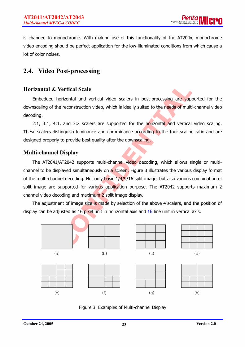
2.4. Video Post-processing
Horizontal & Vertical Scale Embedded horizontal and vertical video scalers in post-processing are supported for the
downscaling of the reconstruction video, which is ideally suited to the needs of multi-channel video
decoding.
2:1, 3:1, 4:1, and 3:2 scalers are supported for the horizontal and vertical video scaling.
These scalers distinguish luminance and chrominance according to the four scaling ratio and are
designed properly to provide best quality after the downscaling.
Multi-channel Display The AT2041/AT2042 supports multi-channel video decoding, which allows single or multi-
channel to be displayed simultaneously on a screen. Figure 3 illustrates the various display format
of the multi-channel decoding. Not only basic 1/4/9/16 split image, but also various combination of
split image are supported for various application purpose. The AT2042 supports maximum 2
channel video decoding and maximum 2 split image display.
The adjustment of image size is made by selection of the above 4 scalers, and the position of
display can be adjusted as 16 pixel unit in horizontal axis and 16 line unit in vertical axis.
(a) (b) (c) (d)
(e) (f) (g) (h)
(a) (b) (c) (d)
(e) (f) (g) (h)
Figure 3. Examples of Multi-channel Display

CONFI
DEN
TIAL
AT2041/AT2042/AT2043 Multi-channel MPEG-4 CODEC
October 24, 2005 Version 2.0 24
2x Zoom Filter The AT2041/AT2042 provides 2x zoom display function magnifying the reconstruction video
twice in the size horizontally and vertically. This zoom filter enables CIF image to be displayed as
D1 size on the screen, and horizontal and vertical zoom can be set independently.
When embedded sync signal is used for video output without external sync signal, additional
glue logic is required for horizontal zoom. Refer to application note ‘AT204x_AN03_Hzoom_
Vxx(Eng).pdf’ for detailed description.
Live & Decoded Video Display Incoming live video can coexist with decompressed video on single screen. The size and offset
of decoded video window can be adjusted.
Live Video
Decoded Video
Live Video
Decoded Video
Figure 4. Live & Decoded Video Display
Background Image When the decompressed video is smaller in size than full screen, background image is useful.
Incoming live video can be displayed on the background and specific color or still image can be
also selected through host interface.
Graphical OSD The AT2041/AT2042 supports 24 bits of graphic OSD (On-Screen Display) with 1 pixel unit.
The details are as below.
1 screen surface
2 screen memory: foreground and background memory
1 pixel resolution
24 bit color, 16 palette
5 level transparency and bypass: 0%, 25%, 50%, 75% and 100%

CONFI
DEN
TIAL
AT2041/AT2042/AT2043 Multi-channel MPEG-4 CODEC
October 24, 2005 Version 2.0 25
3 level blink: no blink, 1Hz and 0.5Hz
Display Layer There are total 3 display layers for AT2041/AT2042, the bottom is background layer, the
medium is playback layer and OSD layer is the top.
OSD Layer
Playback Layer
Background Layer
OSD Layer
Playback Layer
Background Layer
Figure 5. Display Layer
Post-processing Filters The AT2041/AT2042 supports various post-processing filters as below.
Histogram Equalizer
Sharpening Filter
De-interlacing Filter
Brightness Control
Color Bar Generation Color bar pattern generator is embedded in the AT2041/AT2042 for the purpose of video
output test, generating both NTSC and PAL color bar.
Chrominance Format Conversion The decompressed video is outputted as 4:2:2 chrominance format after chrominance format
conversion. This chip provides both chrominance format conversion for interlaced scan and
progressive scan.

CONFI
DEN
TIAL
AT2041/AT2042/AT2043 Multi-channel MPEG-4 CODEC
October 24, 2005 Version 2.0 26
2.5. Video Coding Options
The AT204x supports most of selectable encoding tools provided by the general video
compression standard. These selectable encoding tools can be set independently on video
channel-by-channel at multi-channel encoding.
Video Resolution & Frame Rate Encoding video resolution is supported for a maximum 720 pixels horizontally with 16-pixel
unit as well as a maximum 576 lines vertically with 16-line unit. The video resolution can be
selectable to suite specific needs, and the smallest unit is one macro block with 16 pixels by 16
lines. As for the encoding of interlaced video using MPEG-2 video standard, the vertical line should
be a multiple of 32 lines.
Flexible frame rate allocation to each channel is available ranging from 1 frame to 30 frames
per second. It is also possible to set 1 frame per several seconds for frame rate.
GOP (Group of Pictures) Structure Various GOP structures are supported for MPEG-1, MPEG-2, H.263 and MPEG-4 video standard.
N parameter and M parameter are used to choose GOP structure. N parameter defines period of I-
picture and M parameter determines period of I-picture to P-picture or P-picture to P-picture. M
parameter is not available in H.263 that does not generate B-picture.
For instance, if N=15 and M=3, GOP structure is formed as follows;
I B B P B B P B B P B B P B B I B B … (Coding Order)
B B I B B P B B P B B P B B P B B I … (Display Order)
Closed GOP & Open GOP
AT204x supports both closed GOP and open GOP. Open GOP uses referenced pictures from
the previous GOP at the current GOP boundary. For example, the GOP is open when B pictures at
the start of a GOP rely on I-picture or P-pictures from the immediately previous GOP. Closed GOP
is one that uses no referenced pictures from the previous GOP at the current GOP boundary. For
example, the GOP is closed when it starts with an I-pictures and subsequent B-pictures do not rely
on I-picture or P-pictures from the previous GOP. Closed GOP is ideally suited to the application for
random access or bit stream editing.
This option is applicable to MPEG-1, MPEG-2 and MPEG-4 video standard including B-picture.

CONFI
DEN
TIAL
AT2041/AT2042/AT2043 Multi-channel MPEG-4 CODEC
October 24, 2005 Version 2.0 27
Bit Rate Control & Video Quality Bit rate control can be configured to obtain CBR (Constant Bit Rate) for constant bit rate on
average or VBR (Variable Bit Rate) for constant video quality. Bit rate control is accomplished
basically by controlling quantisation parameter Q, which is set feasibly from level 1 to level 31, and
user can also fix the Q parameter value for specific application. As the parameter Q moves
toward level 1, the picture quality improves but it will generate much bit stream accordingly.
Re-synchronization Methods To cope with the errors that are possibly incurred with network application, re-synchronization
tools are used to notify the system of resynchronization time. A selectable re-sync marker can be
configured for MPEG-4, GOB (Group of Blocks) header for H.263, and Restart Interval Termination
for JPEG. It is mandatory to insert basic slice header for MEPG-1 and MEPG-2.
As for the MPEG-4 Re-sync marker, it can be assigned into the following modes.
To insert the Re-sync marker into periodic macroblock
To insert the Re-sync marker when specific amount of bit stream generates
Not to insert the Re-sync marker in the system application that has a rare error
occurrence.
MPEG-4 Specific Coding Options In addition to the simple profile of MPEG-4 standard, the AT204x supports the additional
coding tool provided by advanced simple profile. Thus, the additional coding tool is not necessary
in case that the compressed video from the AT204x is supposed to be decompressed by another
MPEG-4 decoder which does not support advanced simple profile. The parameter available and
adjustment range are as below.
4-MV mode: ON/OFF
vop_rounding_type: 0/1
intra_dc_vlc_thr: 0 ~ 7
Resynchronization: OFF/#_of_macroblock/#_bits
B-VOP Direct mode: ON/OFF (Advanced Simple Profile)
Method 1/2 Quant: 0/1 (Advanced Simple Profile)
Interlace tools (Advanced Simple Profile)
MPEG-2 Specific Coding Options The parameters and adjustment range available only for MEPG-2 standard are as below.

CONFI
DEN
TIAL
AT2041/AT2042/AT2043 Multi-channel MPEG-4 CODEC
October 24, 2005 Version 2.0 28
intra_dc_precsion: 0 ~ 3
q_scale_type: 0/1
intra_vlc_format: 0/1
alternate_scan: 0/1
2.6. Internal Watermarker
To prevent forgery or alteration of the bit stream after the encoding, hardware watermark
function is built in the AT204x.
Figure 6 illustrates the mechanism of the watermark operation provided by the AT204x. Input
video signal is compressed as bit stream including the digital cryptograph data - also called
‘Watermark’- using 128 bit secrete key in the process of watermark encoding.
If bit stream with watermark are forged, the watermark data in the bit stream are changed
accordingly, which allows forged bit stream to be distinguished. Forged bit stream can be identified
by watermark verification software, which is only for the AT204x and is provided separately.
Forged frame can be detected as well as the forged location in the frame.
The 128 bit secrete key is supposed to be inserted in the bit stream and watermark intensity,
which controls the strength of watermark to be adjusted feasibly. There are no big differences in
the data size and image quality between with watermark and without watermark.
WatermarkEmbedding
Secrete Key
intensityWatermarkVerifying
Secrete Key
intensity
Bit Stream
WatermarkEmbedding
Secrete Key
intensityWatermarkVerifying
Secrete Key
intensity
Bit Stream
Figure 6. Watermark Processing

CONFI
DEN
TIAL
AT2041/AT2042/AT2043 Multi-channel MPEG-4 CODEC
October 24, 2005 Version 2.0 29
2.7. Real-time Trans-coding
The AT2041/AT2042 supports real-time trans-coding that processes re-encoding following by
decoding. It is allowed to change video compression standard, video resolution, frame rate and bit
rate by trans-coding methodology. For example, MPEG-2 bitstream of 720X480 @30Hz can be
transformed to MPEG-4 bit stream of 352X240 @15 Hz.
2.8. Motion Detection
Motion detection functionality is supported for the recording system operating round-the-clock.
The motion detector with macro block-unit-detection is embedded in the AT204x, which performs
precise and appropriate motion detection in low-illuminated conditions from which cause lots of
color noises.
For the application of motion detection, AT204x does not output bit stream when there is no
motion in the video and starts automatically generating the bit stream again when motion resumes.
Audio encoding is still processed even if the video encoding is suspended.
Motion area can be set as small as macro block and motion sensitivity also is controllable.
These parameters are configured independently for each channel in multi-channel encoding.
2.9. Multiplex & De-multiplex
The multiplex engine has flexibility and processes a lot of bitstream rapidly since its engine is
designed by the methodology of hardware combined with software. The maximum bit rate of both
multiplexed bitstream input and output is 50 Mbps.
Multiplexing by Packet The multiplex engine of the AT204x is designed to process multiplex of packetizing method
rapidly while allowing minimum load of embedded RICS. The following multiplexing standards are
supported:
MPEG-1 System Stream (ISO/IEC IS 11172-1)
MPEG-2 PES Stream (ISO/IEC IS 13818-1)
MPEG-2 Program Stream (ISO/IEC IS 13818-1)
MPEG-2 Transport Stream (ISO/IEC IS 13818-1)
In the PES (Packetized Elementary Stream) packet of MPEG-1 and MPEG-2 system, the packet

CONFI
DEN
TIAL
AT2041/AT2042/AT2043 Multi-channel MPEG-4 CODEC
October 24, 2005 Version 2.0 30
can be configured in certain size and be output as picture unit. The stream_id in PES packet
header is used to identify specific channels from the bit stream of the multi-channel encoding.
For detailed information of PES packet header, refer to application note ‘AT204x_AN01_PS_
TYPE1_Vxx(Eng).pdf’.
De-multiplexing for Multi-channel Decoding The de-multiplexing engine supports all of multiplexing standard likewise. In order to
decompress the bit stream from multi-channel encoded bit stream, the channel for decompression
should be assigned. PID (Packet Identifier) need to be configured in the channel to decompress
the bit stream for Transport Stream, the stream_id in PES packet header be configured for
Program Stream and or PES Stream. Single or multi-channel can be selected from the bit stream.
In addition, video compression standard for each channel to be decompressed is required to set as
well.
MPEG-4 Media File Format & AVI File Format MPEG-4 media file format (MP4 file format) and AVI file format differ from the packet
multiplexing method like MPEG-2 program stream. They are formatted as database type file
including information on picture access point, random access point, and etc. Adding DB
information to generated bit stream, which DB information is provided by the AT2041, produces
MP4 file or AVI file.

CONFI
DEN
TIAL
AT2041/AT2042/AT2043 Multi-channel MPEG-4 CODEC
October 24, 2005 Version 2.0 31
3. Description of Signals This section explains signals in accordance with the bus interface. Pin type is defined as I/O =
input and output (bi-directional pin), I = input only and O = output only. A small letter ‘n’ at the
beginning of Pin name means low active signal.
3.1. Video Input Interface
Pin Name Pin Number Types Description
FSYNCIN 4 I field indicator*
VSYNCIN 5 I vertical sync signal*
HSYNCIN 6 I horizontal sync signal*
VVALIDIN 7 I vertical valid data indicator*
HVALIDIN 8 I horizontal valid data indicator*
VDIN7~VDIN0 18,17,16, 14,13,12,
11,9 I video data input
VCLK_ENC 20 I video data clock for video input interface * User may select polarity.
Note that VVALIDIN and HVALIDIN should be pull-up or pull-down externally for embedded
sync mode. The polarities of VVALIDIN and HVALIDIN choose between pull-up and pull-down.
3.2. Video Output Interface
AT2041/AT2042
Pin Name Pin Number Types Description
FSYNCOUT 102 I/O field indicator*
VSYNCOUT 103 I/O vertical sync signal*
HSYNCOUT 104 I/O horizontal sync signal*
VVALIDOUT 100 O vertical valid data indicator*
HVALIDOUT 101 O horizontal valid data indicator*
VDOUT7 ~ VDOUT0
105,106,108, 109,110,111,
112,113 O video data output
VCLK_DEC 115 I video data clock for video output interface * User may select polarity.

CONFI
DEN
TIAL
AT2041/AT2042/AT2043 Multi-channel MPEG-4 CODEC
October 24, 2005 Version 2.0 32
AT2043
Pin Name Pin Number Types Description
NC
100,101,102, 103,104,105, 106,108,109, 110,111,112
113
No connect
VCLK_DEC 115 I Connect to ground
3.3. Audio Interface
Pin Name Pin Number Types Description
AFSR 21 I Frame sync signal receive. For PCM input, it means SYNC of receive signal, and for I2S or Left Justified, it means LRCK of receive signal.
ADR 22 I Data receive. The data rate is equal to the frequency of the ACLK_ENC signal.
ACLK_ENC 25 I Clock input for audio receive signal. Generally, it means BCLK in other audio/codec chips.
AFSX 117 I/O
Signal input in slave mode. Output signal in master mode, which is generate by ACLK_DEC. For PCM output, it means SYNC of transmit signal, and for I2S or Left Justified, it means LRCK of transmit signal.
ADX or NC 118 O
Data output. The data rate is equal to the frequency of the ACLK_DEC signal. * Not connected for AT2043
ACLK_DEC 120 I Clock input for audio transmit signal. Generally, it means BCLK in other audio/codec chips.
3.4. SDRAM Interface
Pin Name Pin Number Types Description
DCLK 143 O SDRAM interface clock
DCLK_FB 137 I
Feedback clock of SDRAM interface clock It is recommended that the feedback clock is generated near to the memory device as possible.
DA12 ~ DA0
122,123,124, 126,127,128, 128,132,134, 135,139,140,
O SDRAM address

CONFI
DEN
TIAL
AT2041/AT2042/AT2043 Multi-channel MPEG-4 CODEC
October 24, 2005 Version 2.0 33
141
DBA1 ~ DBA0 145,146 O SDRAM bank address
nDCAS 148 O SDRAM column address strobe
nDCS 149 O SDRAM chip select
nDRAS 151 O SDRAM row address strobe
nDWE 152 O SDRAM write enable DDQM3 ~ DDQM0
153,156, 157,159 O SDRAM data mask
DD31 ~ DD0
160,161,162, 163,166,167, 170,171,172, 173,174,175, 178,179,181, 182,184,186, 187,188,181, 192,193,194, 96,197,198, 199,202,203,
205,206
I/O SDRAM data
DCKE 207 O SDRAM clock enable
3.5. Host Interface
Pin Name Pin Number Types Description
HD15 ~ HD0
28,29,35,36, 37,39,40,41, 42,44,45,46, 47,48,49,51
I/O host data
HA2 ~HA0 52,53,54 I host address
nCS 58 I chip select
nBS 59 I bus start (pull-up internally)
HCLK 62 I host clock
nWR_RD 63 I data read or write
nOE/RD 64 I data out enable/read
nWAIT/READY 65 O data wait/ready
nIRQ/INT 66 O interrupt request
nBIP 67 I burst progress/end (pull-up internally)
nBURST 68 I burst mode indicator (pull-up internally) * The nWAIT/READY operates as open drain by default.

CONFI
DEN
TIAL
AT2041/AT2042/AT2043 Multi-channel MPEG-4 CODEC
October 24, 2005 Version 2.0 34
3.6. GIO
Pin Name Pin Number Types Description
GIO0/spi_csn 89 I/O General input, output/SPI ROM chip select (Refer to section 9.3.4)
GIO1/spi_hdn 88 I/O General input, output/SPI ROM hold (Refer to section 9.3.4)
GIO2/spi_ck 87 I/O General input, output/SPI ROM clock (Refer to section 9.3.4)
GIO3/spi_do 84 I/O General input, output/SPI ROM data output (Refer to section 9.3.4)
GIO4/spi_di 83 I/O General input, output/SPI ROM data input (Refer to section 9.3.4)
GIO5/rlb 82 I/O General input output/ROM-less boot enable (Refer to section 9.3.1) (pull-down internally)
GIO6/sdram32 81 I/O
General input output /SDRAM data bit width control (Refer to section 9.3.2) (pull-down internally)
GIO7/pull_down 80 I/O
General input output/Should be pull-down (Refer to section 9.3.3) (pull-down internally)
GIO15~GIO8 69,70,71, 74,75,76,
77,78 I/O General input, output
3.7. Miscellaneous
Pin Name Pin Number Types Description
TEST1~TEST0 1,2 I test mode: 00 = normal, 01 = PLL bypass 10 = function test, 11 = PLL test internally pull-down
MC1~MC0 23,24 I multi-channel select / Should be pull-up SYSCLK 31 I external clock input : 28.75MHz
OSC_EB 33 I output of the crystal oscillation IO cell
CPU_SEL2 ~ CPU_SEL0
55,56,57 I CPU type selector: 000 = Xscale 001 = IBM 010 = ARM 011 = Axis 100 = Motorola
CONFI
DEN
TIAL
AT2041/AT2042/AT2043 Multi-channel MPEG-4 CODEC
October 24, 2005 Version 2.0 35
JTAGMODE 90 I JTAG mode select: 0 = ARM JTAG 1 = chip JTAG (pull-down internally)
nTRST 91 I JTAG test reset: input ‘0’ for 10ns or more before starting the normal mode system (pull-up internally)
TDI 92 I JTAG data input
TMS 93 I JTAG test mode select
TCK 94 I JTAG clock
nRESET 96 I AT204x chip hardware reset
TDO 98 O JTAG test data output
RTCK 99 O JTAG returned TCK
IDDQ 208 I IDDQ test mode
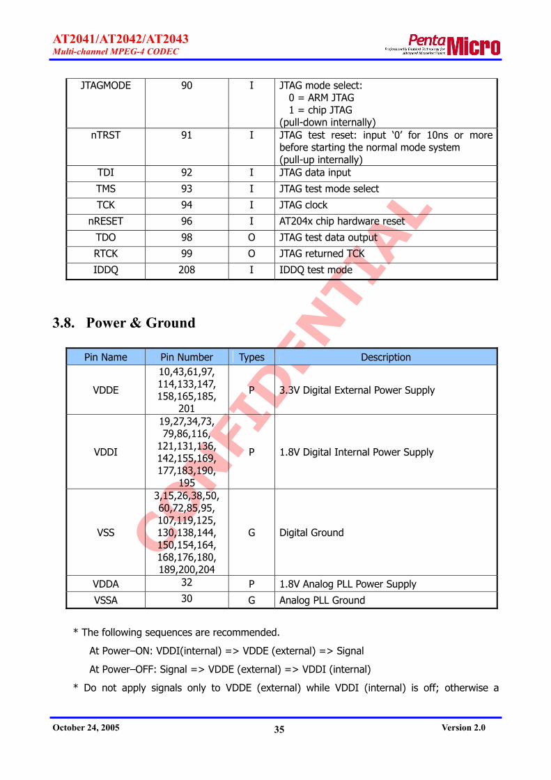
3.8. Power & Ground
Pin Name Pin Number Types Description
VDDE
10,43,61,97, 114,133,147, 158,165,185,
201
P 3.3V Digital External Power Supply
VDDI
19,27,34,73, 79,86,116,
121,131,136, 142,155,169, 177,183,190,
195
P 1.8V Digital Internal Power Supply
VSS
3,15,26,38,50, 60,72,85,95, 107,119,125, 130,138,144, 150,154,164, 168,176,180, 189,200,204
G Digital Ground
VDDA 32 P 1.8V Analog PLL Power Supply
VSSA 30 G Analog PLL Ground
* The following sequences are recommended.
At Power–ON: VDDI(internal) => VDDE (external) => Signal
At Power–OFF: Signal => VDDE (external) => VDDI (internal)
* Do not apply signals only to VDDE (external) while VDDI (internal) is off; otherwise a
CONFI
DEN
TIAL
AT2041/AT2042/AT2043 Multi-channel MPEG-4 CODEC
October 24, 2005 Version 2.0 36
through current may flow, causing potential reliability problems of the LSI.
* External signal level must not be higher than the power supply voltage by 0.5V or more. For
example, when a signal of 3.8V or more is applied to a 3.3V input buffer, it permanently damages
the LSI.
* The level of the PLL power supply must not be higher than that of the standard power
supply (VDDI of dual-power supply) when the power is turned on or off.

CONFI
DEN
TIAL
AT2041/AT2042/AT2043 Multi-channel MPEG-4 CODEC
October 24, 2005 Version 2.0 37
4. Video Input Interface
4.1. Video Input Format
The AT204x can accept video data from a variety of digital video sources. It is specially
designed to glue-less interface with various video decoders. The 8 bit video input port supports
both ITU-R BT.656 and ITU-R BT.601 with embedded or external sync. And 27 MHz is
recommended for input video clock (VCLK_ENC) which shall be lower than system clock, 28.75
MHz. Figure 5 and figure 6 illustrates how the AT204x is connected to commercial video decoders.
Figure 7 shows the interface for external sync and Figure 6 for embedded sync.
IPD[7:0]IGPH
IGPV
IGP0
IDQ
ICLKSAA7114
VD[7:0]
HSYNC
VSYNC
FIELD
VVAILD
HVALID
VCLK
VDIN[7:0]
HSYNCIN
VSYNCIN
FSYNCIN
VVAILDIN
HVALIDIN
VCLK_ENCAT2041
8
VD[15:8]
HSYNC
VSYNC
FIELD
HACTIVE
DVALID
VCLK
VD[15:8]
HRESET
VRESET
FIELD
ACTIVE
DVALID
CLKX2BT829 VCLK AT2041
(a) Philips SAA7114
(c) Conexant BT829
VD[15:8]
HSYNC
VSYNC
FIELD
HACTIVE
DVALID
VCLK
VD[15:8]
HSYNC
VSYNC
FIELD
HACTIVE
DVALID
VCLKTW9903 AT2041
(b) Techwell TW9903
88 VDIN[7:0]
HSYNCIN
VSYNCIN
FSYNCIN
VVAILDIN
HVALIDIN
VCLK_ENC
VDIN[7:0]
HSYNCIN
VSYNCIN
FSYNCIN
VVAILDIN
HVALIDIN
VCLK_ENC
IGP1
Figure 7. Video Decoder Signal Connection for External Sync Mode

CONFI
DEN
TIAL
AT2041/AT2042/AT2043 Multi-channel MPEG-4 CODEC
October 24, 2005 Version 2.0 38
IPD[YOUT[7:0]
PCLK/SCLK
TVP5150
VD[7:0]
HSYNC
VDIN[7:0]
VCLK_ENC
AT2041
8
(a) TI TVP5150
IPD[7:0]VPO[7:0]
LLC
SAA7113
VD[7:0]
HSYNC
VVAILD
HVALID
VDIN[7:0]
VCLK_ENC
AT2041
(b) Philips SAA7113
8IPD[YOUT[7:0]
PCLK/SCLK
TVP5150
VD[7:0]
HSYNC
VDIN[7:0]
VCLK_ENC
AT2041
8
(a) TI TVP5150
IPD[7:0]VPO[7:0]
LLC
SAA7113
VD[7:0]
HSYNC
VVAILD
HVALID
VDIN[7:0]
VCLK_ENC
AT2041
(b) Philips SAA7113
8
Figure 8. Video Decoder Signal Connection for Embedded Sync Mode
Note that VVALIDIN and HVALIDIN should be pull-up or pull-down externally for embedded
sync mode. The polarities of VVALIDIN and HVALIDIN choose between pull-up and pull-down.
4.1.1. External Sync Mode
FSYNCIN, VSYNCIN, HSYNCIN, VVALIDIN, HVALIDIN, VCLK_ENC and VDIN[7:0] are used for
the video input interface in the external sync mode. And all control signals for video input interface
can be sampled at the rising edge or the falling edge of VCLK_ENC and be changed its active
polarity by setting register.
External SYNC consists of operation mode by FSYNCIN, VSYNCIN and HSYNCIN as well as
mode by VSYNCIN and HSYNCIN only. In the External SYNC mode without FSYNCIN, FSYNCIN is
internally made by VSYNCIN and HSYCIN. To draw an analogy of FSYNCIN, Field 0 utilizes the fact
that VSYNCIN’s starting point is very close to that of HSYNCIN. And Field 1 makes use of what
VSYNCIN and HSYNCIN’s starting point changes at some interval. This interval can be adjusted in
register set.
VVALIDIN is used to indicate the valid video lines. And HVALIDIN indicates the valid active
pixels data input during an active video line. Scale-down video is provided using these signals.
Both VVALIDIN and HVALIDIN should be inputted correctly for external sync mode, so total 5
sync signals are used in case of using FSYNCIN.

CONFI
DEN
TIAL
AT2041/AT2042/AT2043 Multi-channel MPEG-4 CODEC
October 24, 2005 Version 2.0 39
525 1 2 3 4 5 6 7 8 9 10 20 21
CVBS
HSYNC
VSYNC
FSYNC
F=0525 1 2 3 4 5 6 7 8 9 10 20 21
CVBS
HSYNC
VSYNC
FSYNC
F=0
CVBS
HSYNC
VSYNC
FSYNC
263 264 265 266 267 268 269 270 271 272 273 283 284
F=1
CVBS
HSYNC
VSYNC
FSYNC
263 264 265 266 267 268 269 270 271 272 273 283 284
F=1
Figure 9. External Sync Format for NTSC
625 1 2 3 4 5 6 7 22 23
CVBS
HSYNC
VSYNC
FSYNC
F=0
624623622 625 1 2 3 4 5 6 7 22 23
CVBS
HSYNC
VSYNC
FSYNC
F=0
624623622
CVBS
HSYNC
VSYNC
FSYNC
310 311 312 313 314 315 316 317 318 319 320 335 336
F=1
CVBS
HSYNC
VSYNC
FSYNC
310 311 312 313 314 315 316 317 318 319 320 335 336
F=1
Figure 10. External Sync Format for PAL

CONFI
DEN
TIAL
AT2041/AT2042/AT2043 Multi-channel MPEG-4 CODEC
October 24, 2005 Version 2.0 40
4.1.2. Embedded Sync Mode
Embedded sync mode only accepts 8 bit data and clock signal as its video input and to comply
with ITU-R BT.656
In case of embedded sync mode VVALIDIN and HVALIDIN signal should be pull-up and ‘video
input sync polarity’ parameter [GID=4,PID=8] of section 10.6.3 should be set to default value
(0x0F).
Sync information is located in the input part where consecutive 8 bit video data are inputted
by the order of FF-00-00-XX. The forth video data contains FSYNCIN, VSYNCIN, HSYNCIN in its
VDIN[6:4] and error correction in VDIN[3:0].
Table 3. Video Timing Reference Codes
Data bit number
First Word
(FF)
Second Word
(00)
Third Word
(00)
Fourth Word
(XY) 7 (MSB) 6 5 4 3 2 1 0
1 1 1 1 1 1 1 1
0 0 0 0 0 0 0 0
0 0 0 0 0 0 0 0
1 F V H P3 P2 P1 P0
F = 0 : during Top Field(First Field), F = 1 : during Bottom Field(Second Field) V = 0 : during Active Display, V = 1 : during Vertical(field) Blanking H = 0 : in SAV (Start of Active Video), H = 1 : in EAV (End of Active Video)

CONFI
DEN
TIAL
AT2041/AT2042/AT2043 Multi-channel MPEG-4 CODEC
October 24, 2005 Version 2.0 41
E
A
V
S
A
V
Active Display (TOP Field)720 x 288
Active Display (BOTTOM Field)
720 x 288
H=1 H=0
F=0(312)
F=1(313)
V=1
V=1
V=1
V=0(288)
V=0(288)
1
22
23
310
311312313
335336
623624625
0 1 2 . . .
719
720
721
722
861
862
863
718. . .
1728T
4T 280T 4T 1440T
B6 AB
9D 80
AB
EC
B6
F1
DA C7
ECF1
E
A
V
S
A
V
Active Display (TOP Field)720 x 288
Active Display (BOTTOM Field)
720 x 288
H=1 H=0
F=0(312)
F=1(313)
V=1
V=1
V=1
V=0(288)
V=0(288)
1
22
23
310
311312313
335336
623624625
0 1 2 . . .
719
720
721
722
861
862
863
718. . .
1728T
4T 280T 4T 1440T
B6 AB
9D 80
AB
EC
B6
F1
DA C7
ECF1
E
A
V
S
A
V
Active Display (TOP Field)720 x 240
Active Display (BOTTOM Field)
720 x 240
H=1 H=0
V=1
V=0(244)
V=0(243)
1
19202122
261262263
264265266
524525
0 1 2 . . .
719
720
721
722
855
856
857
718. . .
1716T
4T 268T 4T 1440T
34 (V=1)
282283284285
3
240
240
B6 AB
9D 80
AB
EC
B6
F1
DA C7
1
15
161718
257
258259
261
0
161718
19
260
258259
261262
Figure 11. Embedded Sync Format for PAL(top) and NTSC(bottom)

CONFI
DEN
TIAL
AT2041/AT2042/AT2043 Multi-channel MPEG-4 CODEC
October 24, 2005 Version 2.0 42
4.2. VBI Data Extraction
The AT204x is designed to read VBI(Vertical Blanking Interval) data and the data can be used
at needs. VBI data can not only be inserted into user data domain of encoding bit stream and used
for the channel index of incoming video input of multi-channel encoding as well.
The maximum number of line to read VBI data is consecutive 4 lines, of which line 48 samples
can be sampled per line. Line location of VBI data and sampling interval in the line can be
configured. In the sampling, 8 bit data is sampled as bit 0 if the data is smaller than a specific
number but sampled as bit 1 if the data is bigger than a specific number. So total 48 bits
information per line and total 192 bits information per filed (4lines per filed) can be transferred to
the AT204x. In general, VBI data is not included up to the tenth line but the AT204x can read VBI
data from any lines except for the first line.

CONFI
DEN
TIAL
AT2041/AT2042/AT2043 Multi-channel MPEG-4 CODEC
October 24, 2005 Version 2.0 43
5. Video Output Interface The video output signals of the AT2041/AT2042 consist of FSYNCOUT, VSYNCOUT, HSYNCOUT,
VVALIDOUT, HVALIDOUT, VDOUT[7:0] and VCLK_DEC. All pins except VCLK_DEC are used to
output pins, when the AT2041/AT2042 is operated as a master. But FSYNCOUT, VSYNCOUT and
HSYNCOUT are used to input pins when the AT2041/AT2042 is operated as a slave. It is possible
to change the polarity of FSYNCOUT, VSYNCOUT, HSYNCOUT, VVALIDOUT and HVALIDOUT.
The AT2041/AT2042 supports interface with various video encoders. Figure 12 shows the
signal connection to the video encoders. Figure 12(a) shows an example used for embedded sync
mode and Figure 12 (b) for slave mode of external sync and Figure 12 (c) and (d) for external
sync master mode.
AT2041
(c) Conexant BT860
MP[7:0]
LLC
SAA7121
VDOUT[7:0]
VCLK_DEC
AT2041
(a) Philips SAA7121
8
8
OSC
MP[7:0]
LLC
SAA7121
VDOUT[7:0]
VCLK_DEC
AT2041
(b) Philips SAA7121
8
OSC
HSYNCOUT
VSYNCOUT
RCV2
RCV1
(d) Conexant BT866
VDOUT[7:0]
VCLK_DEC
HSYNCOUT
VSYNCOUT
HVALIDOUT
VVALIDOUT
FSYNCOUT
BT860
OSC
VID[7:0]
VIDCLK
HSYNC
VSYNC
VIDHACT
VIDVACT
FIELD
VIDVALID AT2041
8VDOUT[7:0]
VCLK_DEC
HSYNCOUT
VSYNCOUT
BT866
OSC
Y7~0
CLK
HSYNC
VSYNC
AT2041
(c) Conexant BT860
MP[7:0]
LLC
SAA7121
VDOUT[7:0]
VCLK_DEC
AT2041
(a) Philips SAA7121
8
8
OSC
MP[7:0]
LLC
SAA7121
VDOUT[7:0]
VCLK_DEC
AT2041
(b) Philips SAA7121
8
OSC
HSYNCOUT
VSYNCOUT
RCV2
RCV1
(d) Conexant BT866
VDOUT[7:0]
VCLK_DEC
HSYNCOUT
VSYNCOUT
HVALIDOUT
VVALIDOUT
FSYNCOUT
BT860
OSC
VID[7:0]
VIDCLK
HSYNC
VSYNC
VIDHACT
VIDVACT
FIELD
VIDVALID AT2041
8VDOUT[7:0]
VCLK_DEC
HSYNCOUT
VSYNCOUT
BT866
OSC
Y7~0
CLK
HSYNC
VSYNC
Figure 12. Signal Connection for Video Encoder Interface

CONFI
DEN
TIAL
AT2041/AT2042/AT2043 Multi-channel MPEG-4 CODEC
October 24, 2005 Version 2.0 44
5.1. Video Format
Output video format of the AT2041/AT2042 supports NTSC or PAL mode compliant with ITU-R
BT.601 and ITU-R BT.656. When the AT2041/AT2042 is used for a master or slave for the video
encoder, NTSC or PAL mode should be selected. Output video format is identical to input video
format of Figure 9, Figure 10 and Figure 11 in Chapter 4.
5.1.1. Embedded Sync mode
ITU-R BT.656 timing(EAV and SAV codes) drives vertical and horizontal timing information to
the video data(VDOUT 7~0). The codes for SAV(Start of Active Video) and EAV(End of Active
Video) are listed on Table 5-1. VDOUT7~0 data in external SYNC mode is identical to those of
embedded sync mode.
Table 4. SAV and EAV Table
F V EAV SAV 0 0 9D 80 0 1 B6 AB 1 0 DA C7 1 1 F1 EC
FF 00 00 XY 80 10 80 10 CB Y CR Y80 10 80 10 FF 00 00 XY CB Y CR Y CB Y CR Y‥‥‥ ‥‥‥
EAV SAVHORIZONTAL BLANKING 720 PIXELS YUV 4:2:2 DATA
1 2 3 4 5 6 7 8 268 270 271 272 273 274 275 276 277 278 279 280 281 282 283 284 1713 1714 1715 1716
(a) ITU-R BT.656 Horizontal Data Format for NTSC 525 Lines/60Hz
FF 00 00 XY 80 10 80 10 CB Y CR Y80 10 80 10 FF 00 00 XY CB Y CR Y CB Y CR Y‥‥‥ ‥‥‥
EAV SAVHORIZONTAL BLANKING 720 PIXELS YUV 4:2:2 DATA
1 2 3 4 5 6 7 8 281 282 283 284 285 286 287 288 289 290 291 292 293 294 295 296 1725 1726 1727 1728
(b) ITU-R BT.656 Horizontal Data Format for PAL 625 Lines/50Hz
4 clocks 4 clocks268 clocks 1440 clocks
4 clocks 4 clocks280 clocks 1440 clocks
FF 00 00 XY 80 10 80 10 CB Y CR Y80 10 80 10 FF 00 00 XY CB Y CR Y CB Y CR Y‥‥‥ ‥‥‥
EAV SAVHORIZONTAL BLANKING 720 PIXELS YUV 4:2:2 DATA
1 2 3 4 5 6 7 8 268 270 271 272 273 274 275 276 277 278 279 280 281 282 283 284 1713 1714 1715 1716
(a) ITU-R BT.656 Horizontal Data Format for NTSC 525 Lines/60Hz
FF 00 00 XY 80 10 80 10 CB Y CR Y80 10 80 10 FF 00 00 XY CB Y CR Y CB Y CR Y‥‥‥ ‥‥‥
EAV SAVHORIZONTAL BLANKING 720 PIXELS YUV 4:2:2 DATA
1 2 3 4 5 6 7 8 281 282 283 284 285 286 287 288 289 290 291 292 293 294 295 296 1725 1726 1727 1728
(b) ITU-R BT.656 Horizontal Data Format for PAL 625 Lines/50Hz
4 clocks 4 clocks268 clocks 1440 clocks
4 clocks 4 clocks280 clocks 1440 clocks
Figure 13. SAV/EAV for ITU-R BT.656 Embedded Sync
5.1.2. External Sync Master mode
When the AT2041/AT2042 is configured for external sync master mode, the FSYNCOUT,

CONFI
DEN
TIAL
AT2041/AT2042/AT2043 Multi-channel MPEG-4 CODEC
October 24, 2005 Version 2.0 45
VSYNCOUT and HSYNCOUT synchronize the external video encoder. And all these signals are
outputs. VVALIDOUT and HVALIDOUT will be asserted high or low in active video data, and size of
VVALIDOUT and HVALIDOUT is fixed.
VideoEncoder
VCLK_OVD_O[7:0]
FSYNC_OVSYNC_OHSYNC_OVVALID_OHVALID_O
AT2041OSC
VideoEncoder
VCLK_OVD_O[7:0]
FSYNC_OVSYNC_OHSYNC_OVVALID_OHVALID_O
AT2041OSC
Figure 14. Connection for External Sync Master Mode
5.1.3. External Sync Slave Mode
In external sync slave mode, the AT2041/AT2042 outputs video data synchronizing with
FSYNCOUT, VSYNCOUT and HSYNCOUT of a video encoder. Output video data can be synchronized
by either FSYNCOUT and HSYNCOUT or VSYNCOUT and HSYNCOUT signals.
The horizontal line is reset by HSYNCOUT, and frame is reset at the moment a field changes
to Field 0. The AT2041/AT2042 identifies the timing of a field change by FSYNCOUT signal or
correlation between VSYNCOUT and HSYNCOUT. The line position of valid video data can be
controlled by vertical offset parameter. Refer to section 11.2.1 and section 11.2.2.
There are some video encoders that must be inputted video clock from an external clock
source in external sync slave mode. In this case, please refer to the master mode for the
connection of VCLK_DEC.
VideoEncoder
VCLK_OVD_O[7:0]
FSYNC_OVSYNC_OHSYNC_OVVALID_OHVALID_O
AT2041
VideoEncoder
VCLK_OVD_O[7:0]
FSYNC_OVSYNC_OHSYNC_OVVALID_OHVALID_O
AT2041
Figure 15. Connection for External Sync Slave Mode

CONFI
DEN
TIAL
AT2041/AT2042/AT2043 Multi-channel MPEG-4 CODEC
October 24, 2005 Version 2.0 46
5.2. VBI Insertion
The AT2041/AT2042 can insert VBI(Video Blanking Interval) data in the output video. The
maximum number of line to output VBI is consecutive 4 lines and each line can carry 48 bits. The
line location of VBI data and repetition cycle of each bit in the line can be configured.
The AT2041/AT2042 cannot insert different VBI data into field by field, but frame by frame.
And VBI data synchronized by decoded frame is inserted in the output video asynchronously; it is
impossible to insert VBI data in the output video synchronously.

CONFI
DEN
TIAL
AT2041/AT2042/AT2043 Multi-channel MPEG-4 CODEC
October 24, 2005 Version 2.0 47
6. Audio Interface The AT204x supports PCM, I2S, Left Justified and Stream mode for audio interface. And it can
accept the inputs with PCM format of 1 channel to 16 channels. In case of both I2S and Left
Justified mode, only 1 channel input/output is supported. For detailed information of audio
interface, refer to application note ‘AT204x_AN10_Audio_Interface_Vxx(Eng).pdf’.
6.1. PCM Mode
The AT204x can accept PCM data of 1 channel, 2 channel, 4 channel, 8 channel and 16
channels. In addition, it provides 1 bit delay mode for input and output data to support various
formats.
ch.1 ch.2 ch.16
frame sync width
8 clock cycles (8 bits)
128 clock cycles (128 bits)
ACLK_ENC/ACLK_DEC
AFSR/AFSX
ADR/ADX ch.1 ch.2 ch.16
frame sync width
8 clock cycles (8 bits)
128 clock cycles (128 bits)
ACLK_ENC/ACLK_DEC
AFSR/AFSX
ADR/ADX
(a) no delay
ch.1 ch.2 ch.16
frame sync width
8 clock cycles (8 bits)
128 clock cycles (128 bits)
ACLK_ENC/ACLK_DEC
AFSR/AFSX
ADR/ADX ch.1 ch.2 ch.16
frame sync width
8 clock cycles (8 bits)
128 clock cycles (128 bits)
ACLK_ENC/ACLK_DEC
AFSR/AFSX
ADR/ADX
(b) 1 bit delay
Figure 16. PCM Mode Timing Diagram

CONFI
DEN
TIAL
AT2041/AT2042/AT2043 Multi-channel MPEG-4 CODEC
October 24, 2005 Version 2.0 48
Figure 16 shows the timing diagram in PCM mode. (a) of no delay mode shows that valid data
starts with frame sync from the same clock cycle. And (b) of 1 bit delay mode shows that valid
data starts at one clock after frame sync.
Input channel can be selected among 4, 8 and 16 channels (8 bit per channel). An additional
hardware chip is required between PCM chip and the AT204x to implement 8 channels or 16
channels using Quad PCM chip.
Table 5 shows the recommended relationship between frame sync width and data bit width.
For example, when data bit width is 32 bit (4 channel x 8 bit) for 4 channel, frame sync width is
more than 32. When frame sync width is 64 and sampling frequency is 8 kHz, external clock
(ACLK_ENC/ ACLK_DEC) of 512 kHz (8 kHz x 64) is required.
Table 5. Frame Sync Width in PCM Mode - Encoding
32 < frame_sync_width ≤ 1024
frame_sync_width > data_bit_width
Table 6 (a) shows the recommended frame sync width and data bit width for audio decoding
in master mode. Table 6 (b) is a numerical expression to calculate sampling frequency.
Table 6. Frame Sync Width in PCM mode - Decoding
(a) Frame Sync Width & Data Bit Width
256 ≤ frame_sync_width ≤ 1024
data bit width = 32
(b) The relationship between sampling frequency and frame sync width
sampling frequency = ACLK_ENC / frame_sync_width
For Example,
8 kHz = 2,048 MHz / 256

CONFI
DEN
TIAL
AT2041/AT2042/AT2043 Multi-channel MPEG-4 CODEC
October 24, 2005 Version 2.0 49
6.2. I2S , Left Justified Mode
The AT204x supports general audio interfaces such as I2S and Left Justified. The timing
diagrams for audio interface are shown on Figure 17 and Figure 18.
frame sync width
16 or 32 bits
ACLK_ENC/ACLK_DEC
AFSR/AFSX
ADR/ADX
MSB LSB
frame sync width
16 or 32 bits
ACLK_ENC/ACLK_DEC
AFSR/AFSX
ADR/ADX
MSB LSB
Figure 17. I2S Mode Timing Diagram
frame sync width
16 or 32 bits
ACLK_ENC/ACLK_DEC
AFSR/AFSX
ADR/ADX
MSB LSB
frame sync width
16 or 32 bits
ACLK_ENC/ACLK_DEC
AFSR/AFSX
ADR/ADX
MSB LSB
Figure 18. Left Justified Mode Timing Diagram
The data width for general I2S and Left Justified mode are inputted or outputted in 16 bits, 20
bits or 24 bits. However, the AT204x supports 16 bits and 32 bits widths only. To accept 20 bit or
24 bit audio data, the AT204x is to be set as 32 bits mode.
Table 7 shows the recommended relationship between frame sync mode and data bit width for
I2S and Left Justified mode. The required frequency of external clock (ACLK_ENC, ACLK_DEC) is
(frame_sync_width x sampling_frequency). For example, when sampling frequency is 32 kHz and
frame sync width is 64 bit, external clock (ACLK_ENC, ACLK_DEC) is 2.048 MHz.

CONFI
DEN
TIAL
AT2041/AT2042/AT2043 Multi-channel MPEG-4 CODEC
October 24, 2005 Version 2.0 50
Table 7. Frame Sync Width in I2S/Left-Justified mode - Encoding
(data_bit_per_channel + 1) * 2 ≤ frame_sync_width ≤ 256
For example, if data bit per channel is 16, frame sync width is more than 32.
(16 + 1) x 2 ≤ 32 ≤ 256 not OK
(16 + 1) x 2 ≤ 64 ≤ 256 OK
Table 8 (a) shows the recommended frame sync width and data bit width for audio decoding
in master mode. Table 8 (b) is a numerical expression to calculate sampling frequency.
Table 8. Frame Sync Width in I2S/Left-Justified mode - Decoding
(a) Frame Sync Width & Data Bit Width
I2S mode:
(data_bit_per_channel + 3) * 2 ≤ frame_sync_width ≤ 256
Left-justified mode:
(data_bit_per_channel + 2) * 2 ≤ frame_sync_width ≤ 256
For example, if data bit per channel is 16, frame sync width is more than 32.
(16 + 2) x 2 ≤ 32 ≤ 256 not OK
(16 + 2) x 2 ≤ 64 ≤ 256 OK
(b) The relationship between sampling frequency and frame sync width
sampling frequency = ACLK_ENC / frame_sync_width
For Example,
32 kHz = 2,048 MHz / 64 // 16-bit stereo

CONFI
DEN
TIAL
AT2041/AT2042/AT2043 Multi-channel MPEG-4 CODEC
October 24, 2005 Version 2.0 51
6.3. Master / Slave Mode
The AT204x supports both master mode and slave mode for audio interface. When the
AT240x operates as master mode, AFSR is input and AFSX is output, and user can customize the
frequency of external audio clock using ACLK_DEC clock. When the AT204x operates as slave
mode, both AFSR and AFSX are input.

CONFI
DEN
TIAL
AT2041/AT2042/AT2043 Multi-channel MPEG-4 CODEC
October 24, 2005 Version 2.0 52
7. External SDRAM Interface The AT204x requires external SDRAM to store the following data.
Firmware program code & data
Video & audio data
MBI (macro-block information) data
Stream data
OSD data
7.1. SDRAM Requirement
The external SDRAM should be guaranteed following requirements.
Speed: 133MHz
Data bit width: 16-bit (2EA) or 32-bit (1EA)
Number of bank: 4
Auto-refresh: 8192cycles/64msec or less
Size: 64Mbit or more (see the section 7.3 SDRAM Size)
7.2. SDRAM Operation Mode
The external SDRAM for the AT204x is operated as following modes.
Burst length (BL) = 4
CAS latency (CL) = 3
Write burst mode = burst
7.3. SDRAM Size
Required memory size depends on whether the AT204x is used for CODEC or encoder only.
Table 9 describes SDRAM size depending on the number of channel and GOP structure for CODEC
mode, and Table 10 describes SDRAM size for encoder only mode.
For SDRAM size, there is not decoder only mode.
SDRAM size could be changed in case by case.

CONFI
DEN
TIAL
AT2041/AT2042/AT2043 Multi-channel MPEG-4 CODEC
October 24, 2005 Version 2.0 53
Table 9. SDRAM Size for Codec (AT2041, AT2042), Mbit
CH
GOP M 1 2 4 8 9 16
1 128 256 256 512 512 512
2 128 256 256 512 512 1024
3 128 256 256 512 512 1024
Table 10. SDRAM Size for Encoder (AT2043), Mbit
CH
GOP M 1 2 4 8 9 16
1 64 64 128 256 256 512
2 64 128 128 256 256 512
3 64 128 256 256 512 512
7.4. SDRAM Signal Connection
The AT204x makes use of either two 16-bit SDRAM or one 32-bit SDRAM. (see ‘SDRAM Data
Bit Width Control (sdram32/GIO[6])‘ in section 9.3.2) Figure 19 and Figure 20 show the interface
with 16-bit SDRAM and 32-bit SDRAM, respectively.

CONFI
DEN
TIAL
AT2041/AT2042/AT2043 Multi-channel MPEG-4 CODEC
October 24, 2005 Version 2.0 54
.DCLK_FB
DCLK
DCKE
nDCS
nDRAS
nDCAS
nDWE
DA[12:0]
DBA[1:0]
DDQM[3:0]
DD[31:0]
DCLK_FB
DCLK
DCKE
nDCS
nDRAS
nDCAS
nDWE
DA[12:0]
DBA[1:0]
DDQM[3:0]
DD[31:0]
AT2041 SDRAM
CLK
CKE
nCS
nRAS
nCAS
nWE
A[12:0]
BA[1:0]
DQM[3:0]
DQ[31:0]
CLK
CKE
nCS
nRAS
nCAS
nWE
A[12:0]
BA[1:0]
DQM[3:0]
DQ[31:0]32
115MHz
Feedback clock
R
Figure 19. SDRAM Signal Connection (32-bit SDRAM x 1)
.
.
.
.
.
.....
.DCLK_FB
DCLK
DCKE
nDCS
nDRAS
nDCAS
nDWE
DA[12:0]
DBA[1:0]
DDQM[3:0]
DD[31:0]
DCLK_FB
DCLK
DCKE
nDCS
nDRAS
nDCAS
nDWE
DA[12:0]
DBA[1:0]
DDQM[3:0]
DD[31:0]
AT2041 SDRAM
32
115MHz
Feedback clock
CLK
CKE
nCS
nRAS
nCAS
nWE
A[12:0]
BA[1:0]
DQM[3:0]
DQ[31:16]
CLK
CKE
nCS
nRAS
nCAS
nWE
A[12:0]
BA[1:0]
DQM[3:0]
DQ[31:16]
SDRAM
CLK
CKE
nCS
nRAS
nCAS
nWE
A[12:0]
BA[1:0]
DQM[3:0]
DQ[15:0]
CLK
CKE
nCS
nRAS
nCAS
nWE
A[12:0]
BA[1:0]
DQM[3:0]
DQ[15:0]
R
Figure 20. SDRAM Signal Connection (16-bit SDRAM x 2)

CONFI
DEN
TIAL
AT2041/AT2042/AT2043 Multi-channel MPEG-4 CODEC
October 24, 2005 Version 2.0 55
The AT204x provides the high-speed interface (115MHz) with SDRAM using feedback clock as
shown in above figures. As the feedback clock is used for re-timing of input/output signals
pertaining to SDRAM, the AT204x ensures more stable operation. Feedback clock should branch off
the nearest point from CLK pin of SDRAM, input to DCLK_FB. In circuit (Printed Circuit Board)
design, SDRAM should be positioned at the nearest area from the AT204x and designed with
circuits that all SDRAM signals have the short and the same trace lengths.

CONFI
DEN
TIAL
AT2041/AT2042/AT2043 Multi-channel MPEG-4 CODEC
October 24, 2005 Version 2.0 56
8. Host Interface The AT204x supports IBM, Motorola, ARM, Xscale and Axis CPU interface without additional
glue logic.
8.1. Host Interface Unit Architecture
A detailed block diagram of HIU (Host Interface Unit) is shown in Figure 21. There are two
registers (status register and command register) and four FIFOs (Tx FIFO, Rx FIFO, Multiplex FIFO
and De-multiplex FIFO) for the host interface. Table 11 provides local address to select register or
FIFO.
Tx FIFO
Rx FIFO
Multiplex FIFO
De-multiplex FIFO
ExternalCPU
interface
ARM946EInterface
Command Register
Status Register
Tx FIFO
Rx FIFO
Multiplex FIFO
De-multiplex FIFO
ExternalCPU
interface
ARM946EInterface
Command Register
Status Register
Figure 21. Host Interface Block Diagram

CONFI
DEN
TIAL
AT2041/AT2042/AT2043 Multi-channel MPEG-4 CODEC
October 24, 2005 Version 2.0 57
Table 11. Host Interface Address Map
HA[2:0] Selected Register/FIFO
000 Multiplex FIFO
001 De-multiplex FIFO
010 Tx FIFO
011 Rx FIFO
100 Command Register
101 Reserved
110 Status Register
111 Reserved
8.2. Register and FIFO Access
This section explains the detailed operation of two registers and four FIFOs.
8.2.1. Status Register
This status registers are read only. The CPU may read it at any time to check FIFO status. For
reading data from this register, CPU should access data using single transfer mode. i.e., both
nBURST and nBIP should be ‘high’. These two signals are internally pull-up. Table 12 shows
meaning of the each bit.
Table 12. Status Register
Bit Description Bit Description
0 Reserved 8 Tx FIFO Empty
1 Reserved 9 Tx FIFO Full
2 Reserved 10 Rx FIFO Empty
3 Reserved 11 Rx FIFO Full
4 Reserved 12 Multiplex FIFO Empty
5 Reserved 13 Multiplex FIFO Full
6 Multiplex FIFO Almost Empty 14 De-multiplex FIFO Empty
7 De-multiplex FIFO Almost Full 15 De-multiplex FIFO Full
* When each bit is ‘1’, it signifies a correspond meaning.

CONFI
DEN
TIAL
AT2041/AT2042/AT2043 Multi-channel MPEG-4 CODEC
October 24, 2005 Version 2.0 58
8.2.2. Command Register
This command registers are write-only. The CPU writes these registers at any time to control
internal signals that are used for internal RISC. For writing data to this register, CPU should access
data using single transfer mode. i.e., both nBURST and nBIP should be ‘high’. These two signals
are internally pull-up. Table 13 provides meaning of the each command.
Table 13. Command Register
HD[15:0] Description
xxxx_xxxx_0000_0000 no operation
xxxx_xxxx_0000_0001 SDRAM access enable
xxxx_xxxx_0000_0010 SDRAM scheduler start
xxxx_xxxx_0000_0100 SDRAM access disable
xxxx_xxxx_0000_1000 SDRAM scheduler stop
SDRAM access enable: Allowing RISC in AT204x to access SDRAM
SDRAM scheduler start: Starting SDRAM schedule in AT204x
SDRAM access disable: Not allowing RISC in AT204x to access SDRAM
SDRAM scheduler stop: Stopping SDRAM schedule in AT204x
SDRAM scheduler in the AT204x does not operate immediately after reset. In ROM boot mode
(rlb/GIO[5] = 0, see 9.3.1), internal RISC enables SDRAM scheduler to operate. However, in ROM-
less boot mode (rlb/GIO[5] = 1, see 9.3.1), host processor should start SDRAM scheduler by
setting ‘SDRAM scheduler start’ command to this register.
In ROM-less boot mode, RISC processor is not allowed to access SDRAM after reset. Thus,
when RISC processor tries to read data from SDRAM, RISC will be suspended on WAIT status. In
this case, host processor can allow RISC to access SDRAM by setting ‘SDRAM access enable’
command to this register.
8.2.3. Rx FIFO Access
Rx FIFO with 16 depths is used to send data ID and data and it sends all related parameters
for driving the AT204x to the RISC.
For writing data to this FIFO, CPU must access data using single transfer mode and both
nBURST and nBIP should be ‘high’ state. These two signals are internally pull-up.

CONFI
DEN
TIAL
AT2041/AT2042/AT2043 Multi-channel MPEG-4 CODEC
October 24, 2005 Version 2.0 59
8.2.4. Tx FIFO Access
Tx FIFO, which has 16 depths, is used to monitor internal system data such as system status.
Tx FIFO operation can be altered at needs.
For reading data from this register, CPU must access data using single transfer mode and both
nBURST and nBIP must be ‘high’. These two signals are internally pull-up.
8.2.5. Multiplex FIFO Read
Multiplex FIFO with 32 depths is used to read encoded bit stream from external host controller.
Multiplex FIFO can read data as single mode or burst mode. The burst length is ‘4’ when
transferring data as burst mode.
8.2.6. De-multiplex FIFO Write
De-multiplex FIFO with 32 depths, writing data as single mode or burst mode, is used to write
bit stream that is supposed to be decompressed.
The burst length is ‘4’ when host transfers data as burst mode.
8.3. Timing diagram
The following illustrates the timing diagram to read or write data from/to registers as well as
FIFO.
nWAIT signal may be delayed by the status of Read/Write FIFO. If FIFO is full, nWAIT for
writing operation is delayed until FIFO is not full, and if FIFO is empty, nWAIT for reading
operation is delayed until FIFO is not empty.
In case of IBM type CPU, nCS, nWR_RD and nOE/RD should be maintained as ‘high’ at next
clock after nWAIT is high.

CONFI
DEN
TIAL
AT2041/AT2042/AT2043 Multi-channel MPEG-4 CODEC
October 24, 2005 Version 2.0 60
8.3.1. Single Read
Single Read Timing for MPC-850 CPU
HCLK
HA[2:0]
nWR_RD
nBS
HD[15:0]
nWAIT/READY
nBURST
nBIP
nCS
High
High
HCLK
HA[2:0]
nWR_RD
nBS
HD[15:0]
nWAIT/READY
nBURST
nBIP
nCS
High
High
Figure 22. Single Read Timing for MPC-850
Single Read Timing for IBM Type CPU
HCLK
HA[2:0]
nWR_RD
nCS
nOE/RD
HD[15:0]
nWAIT/READY
nBURST
nBIP
HCLK
HA[2:0]
nWR_RD
nCS
nOE/RD
HD[15:0]
nWAIT/READY
nBURST
nBIP
Figure 23. Single Read Timing for IBM PowerPC

CONFI
DEN
TIAL
AT2041/AT2042/AT2043 Multi-channel MPEG-4 CODEC
October 24, 2005 Version 2.0 61
8.3.2. Single Write
Single Write Timing for MPC-850 CPU
High
High
HCLK
HA[2:0]
nWR_RD
nBS
HD[15:0]
nWAIT/READY
nBURST
nBIP
nCS
High
High
HCLK
HA[2:0]
nWR_RD
nBS
HD[15:0]
nWAIT/READY
nBURST
nBIP
nCS
Figure 24. Single Write Timing for MPC-850
Single Write Timing for IBM Type CPU
HCLK
HA[2:0]
nWR_RD
nCS
nOE/RD
HD[15:0]
nWAIT/READY
nBURST
nBIP
Figure 25. Single Write Timing for IBM PowerPC

CONFI
DEN
TIAL
AT2041/AT2042/AT2043 Multi-channel MPEG-4 CODEC
October 24, 2005 Version 2.0 62
8.3.3. Burst Read
Burst Read Timing for MPC-850 CPU
D0 D1 D3D2
HCLK
HA[2:0]
nWR_RD
nBS
nBURST
nBIP
HD[15:0]
nWAIT/READY
nCS
Figure 26. Burst Read Timing for MPC-850
Burst Read Timing for IBM Type CPU
D0 D1 D2 D3
HCLK
HA[2:0]
nWR_RD
nCS
nOE/RD
HD[15:0]
nWAIT/READY
nBURST
nBIP
D0 D1 D2 D3
HCLK
HA[2:0]
nWR_RD
nCS
nOE/RD
HD[15:0]
nWAIT/READY
nBURST
nBIP
Figure 27. Burst Read Timing for IBM PowerPC

CONFI
DEN
TIAL
AT2041/AT2042/AT2043 Multi-channel MPEG-4 CODEC
October 24, 2005 Version 2.0 63
8.3.4. Burst Write
Burst Write Timing for MPC-850 CPU
D0 D1 D3D2
HCLK
HA[2:0]
nWR_RD
nBS
nBURST
nBIP
HD[15:0]
nWAIT/READY
nCS
Figure 28. Burst Write Timing for MPC-850
Burst Write Timing for IBM Type CPU
D1D0 D2 D3
HCLK
HA[2:0]
nWR_RD
nCS
nOE/RD
HD[15:0]
nWAIT/READY
nBURST
nBIP
Figure 29. Burst Write Timing for IBM PowerPC

CONFI
DEN
TIAL
AT2041/AT2042/AT2043 Multi-channel MPEG-4 CODEC
October 24, 2005 Version 2.0 64
8.4. Signal Mapping
The AT204x supports IBM, Motorola, ARM, Xscale and Axis CPU interface without additional
glue logic. The microprocessors those are able to interface to the AT204x without glue logic are as
follows:
IBM39STB034xx
IBM39STB043xx
405EP
405GR(r)
PXA25x
HMS39C7092
S3C2800
S3C2501x
TMPR4925
MPC850
MPC8245
Local interface of PCI9054
Most CPUs supporting Variable Latency I/O
The CPU mode is set using CPU_SEL[2:0]. Table 14 shows the characteristic of the CPU mode.
Table 14. CPU mode of The AT204x
CPU_SEL [2:0]
CPU mode
nWAIT/READYPolarity
nIRQ/INT Polarity nBS Burst
Mode Remark
3’b 000 Xscale High Falling X X
3’b 001 IBM High Rising X O
3’b 010 ARM High Rising X X Clock Invert
3’b 011 Axis High Falling X X
3’b 100 Motorola Low Falling O O ** nWAIT/READY and nIRQ/INT are high-z in inactive state. Therefore external pull-up/down
are needed.
Refer to the AT204x application note, ‘AT204x_AN06_Host_Interface_Vxx(eng).pdf’, for
detailed information about host controller interface.
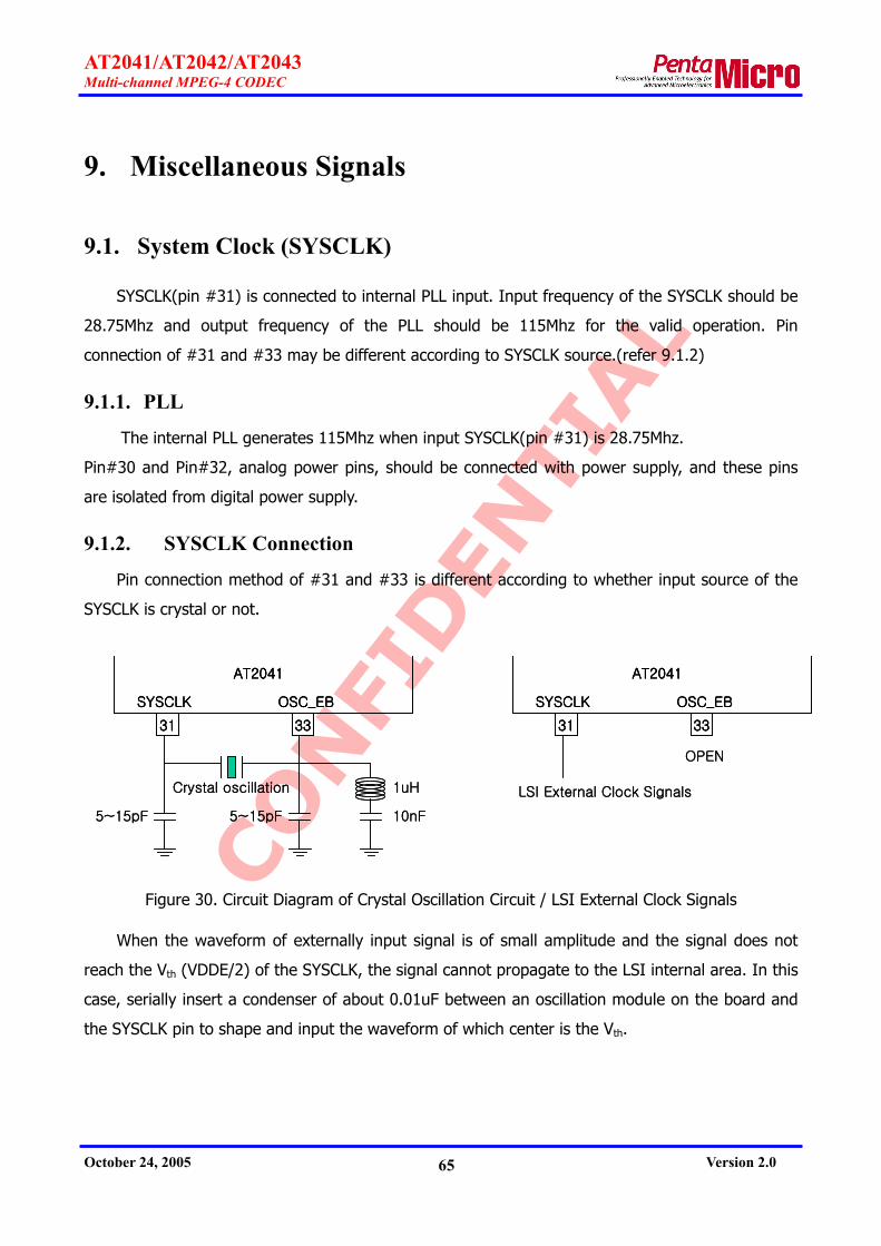
CONFI
DEN
TIAL
AT2041/AT2042/AT2043 Multi-channel MPEG-4 CODEC
October 24, 2005 Version 2.0 65
9. Miscellaneous Signals
9.1. System Clock (SYSCLK)
SYSCLK(pin #31) is connected to internal PLL input. Input frequency of the SYSCLK should be
28.75Mhz and output frequency of the PLL should be 115Mhz for the valid operation. Pin
connection of #31 and #33 may be different according to SYSCLK source.(refer 9.1.2)
9.1.1. PLL
The internal PLL generates 115Mhz when input SYSCLK(pin #31) is 28.75Mhz.
Pin#30 and Pin#32, analog power pins, should be connected with power supply, and these pins
are isolated from digital power supply.
9.1.2. SYSCLK Connection
Pin connection method of #31 and #33 is different according to whether input source of the
SYSCLK is crystal or not.
Crystal oscillation
5~15pF 5~15pF 10nF
1uH
31 33
SYSCLK OSC_EB
AT2041
Crystal oscillation
5~15pF 5~15pF 10nF
1uH
31 33
SYSCLK OSC_EB
AT2041
31 33
SYSCLK OSC_EB
AT2041
31 33
SYSCLK OSC_EB
AT2041
OPEN
LSI External Clock Signals
31 33
SYSCLK OSC_EB
AT2041
31 33
SYSCLK OSC_EB
AT2041
OPEN
LSI External Clock Signals
Figure 30. Circuit Diagram of Crystal Oscillation Circuit / LSI External Clock Signals
When the waveform of externally input signal is of small amplitude and the signal does not
reach the Vth (VDDE/2) of the SYSCLK, the signal cannot propagate to the LSI internal area. In this
case, serially insert a condenser of about 0.01uF between an oscillation module on the board and
the SYSCLK pin to shape and input the waveform of which center is the Vth.

CONFI
DEN
TIAL
AT2041/AT2042/AT2043 Multi-channel MPEG-4 CODEC
October 24, 2005 Version 2.0 66
9.1.3. Noise Countermeasures in Oscillation Circuit
The IC and the crystal oscillator must be as close as possible for short wiring.
The oscillation circuit GND must be as close to the IC GND (Vss) as possible
A wiring pattern with a large current driving must not be near the oscillation circuit.
The GND pattern must be wide to prevent interference by other signals.
Cut the pattern or do not make any pattern on the board.
9.2. H/W Reset
The nRESET is hardware reset of the AT204x. It should be reset when SYSCLK is in clock
because the type of nRESET is synchronous one. The reset state is maintained inside the AT204x
for a while just after reset externally. Figure 31 shows timing of nRESET.
SYSCLK
nRESET
minimum 3 SYSCLK cyclesInternal nReset
10,000 SYSCLK cycles
Figure 31. nRESET Timing
9.3. GIO
The AT204x provides 16 GIO pins. Each GIO pin can be programmed as input, output or
external interrupt. Some pins provide additional alternative functions.
GIO pins, not specified in this datasheet, should not be utilized for designs adopting the
AT204x. Undefined GIO pins can be specified in the future, if necessary, and pins are supposed to
be used as defined.
9.3.1. ROM-less Boot Enable (rlb/GIO[5])
The AT204x can start operation either by reading program from ROM or by uploading program
from the host controller. In the former booting mode, rlb/GIO[5] should be ‘0’ during reset. In the
latter booting mode, case that the AT204x rlb/GIO[5] should be ‘1’ during reset. The rlb/GIO[5]

CONFI
DEN
TIAL
AT2041/AT2042/AT2043 Multi-channel MPEG-4 CODEC
October 24, 2005 Version 2.0 67
operates the same as normal GIO pins after reset.
9.3.2. SDRAM Data Bit Width Control (sdram32/GIO[6])
Either two 16-bit SDRAM or one 32-bit SDRAM can be used with AT204x.
During reset, sdram32/GIO[6] should be ‘0’ when using two 16-bit SDRAM or it should be ‘1’ when
using one 32-bit SDRAM.
The sdram32/GIO[6] operates the same as normal GIO pins after reset.
9.3.3. SDRAM Test Mode Enable (pull_down/GIO[7])
The pull_down/GIO[7] is used for chip test purpose. During reset, The pull_down/GIO[7]
should be ‘0’. Normal operation can not be guaranteed when pull_down/GIO[7] is ‘1’.
The pull_down/GIO[7] operates as indicator for horizontal zoom after reset. In case of
horizontal zoom operation the pull_down/GIO[7] outputs ‘1’. Refer to the AT204x application note,
‘AT204x_AN03_HZoom_Vxx(Eng).pdf’, for the detailed information about horizontal zoom.
9.3.4. SPI Serial ROM Interface
In ROM booting mode, when rlb/GIO[5] is ‘0’, the AT204x uses SPI serial ROM. The AT204x
interfaces with external SPI serial ROM though GIO[4:0] as shown in Figure 32. SPI Serial ROM
input clock should be 14.375MHz, and AT204x support various ROM size up to 512 Kbytes. AT204x
supports read, write protection, page program, sector erase, bulk erase, power down.
spi_csn/GIO[0]
spi_hdn/GIO[1]
spi_ck/GIO[2]
spi_di/GIO[4]
spi_do/GIO[3]
AT204x
csn
hdn
ck
do
di
SPI Serial ROM
spi_csn/GIO[0]
spi_hdn/GIO[1]
spi_ck/GIO[2]
spi_di/GIO[4]
spi_do/GIO[3]
AT204x
csn
hdn
ck
do
di
SPI Serial ROM
Figure 32. SPI Serial ROM Signal Connection
In case of not using ROM, GIO[4:0] can be programmed to operate as normal GIO.
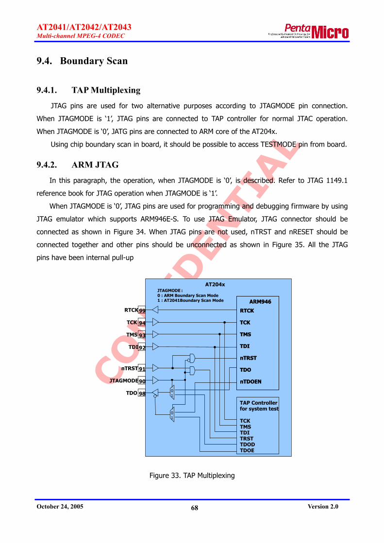
CONFI
DEN
TIAL
AT2041/AT2042/AT2043 Multi-channel MPEG-4 CODEC
October 24, 2005 Version 2.0 68
9.4. Boundary Scan
9.4.1. TAP Multiplexing
JTAG pins are used for two alternative purposes according to JTAGMODE pin connection.
When JTAGMODE is ‘1’, JTAG pins are connected to TAP controller for normal JTAC operation.
When JTAGMODE is ‘0’, JATG pins are connected to ARM core of the AT204x.
Using chip boundary scan in board, it should be possible to access TESTMODE pin from board.
9.4.2. ARM JTAG
In this paragraph, the operation, when JTAGMODE is ‘0’, is described. Refer to JTAG 1149.1
reference book for JTAG operation when JTAGMODE is ‘1’.
When JTAGMODE is ‘0’, JTAG pins are used for programming and debugging firmware by using
JTAG emulator which supports ARM946E-S. To use JTAG Emulator, JTAG connector should be
connected as shown in Figure 34. When JTAG pins are not used, nTRST and nRESET should be
connected together and other pins should be unconnected as shown in Figure 35. All the JTAG
pins have been internal pull-up
99
94
93
92
91
90
RTCK
TCK
TMS
TDI
nTRST
JTAGMODE
TDO 98
RTCK
TCK
TMS
TDI
nTRST
TDO
nTDOEN
ARM946
RTCK
TCK
TMS
TDI
nTRST
TDO
nTDOEN
ARM946
01
01
TCKTMSTDITRSTTDODTDOE
TAP Controller for system test
AT204xJTAGMODE :0 : ARM Boundary Scan Mode1 : AT2041 Boundary Scan Mode
Figure 33. TAP Multiplexing

CONFI
DEN
TIAL
AT2041/AT2042/AT2043 Multi-channel MPEG-4 CODEC
October 24, 2005 Version 2.0 69
..
.
.
...
nTRST
TDI
TMS
TCK
RTCK
TDO
nRESET
1
3
5
7
9
11
13
15
17
19
2
4
6
8
10
12
14
16
18
20
10K 10K 10K 10K
470
. . . .
.
.
.....
System reset
AT204x
JTAG Connector
.
...
.
.
...
nTRST
TDI
TMS
TCK
RTCK
TDO
nRESET
1
3
5
7
9
11
13
15
17
19
2
4
6
8
10
12
14
16
18
20
10K 10K 10K 10K
470
. . . .
.
.
.....
System reset
AT204x
JTAG Connector
.
.
Figure 34. JTAG Signal Connection (20-Pin Connector)
.
nTRST
TDI
TMS
TCK
RTCK
TDO
nRESET System reset
AT204x
.
nTRST
TDI
TMS
TCK
RTCK
TDO
nRESET System reset
AT204x
Figure 35. JTAG Signal Connection for Unused Case
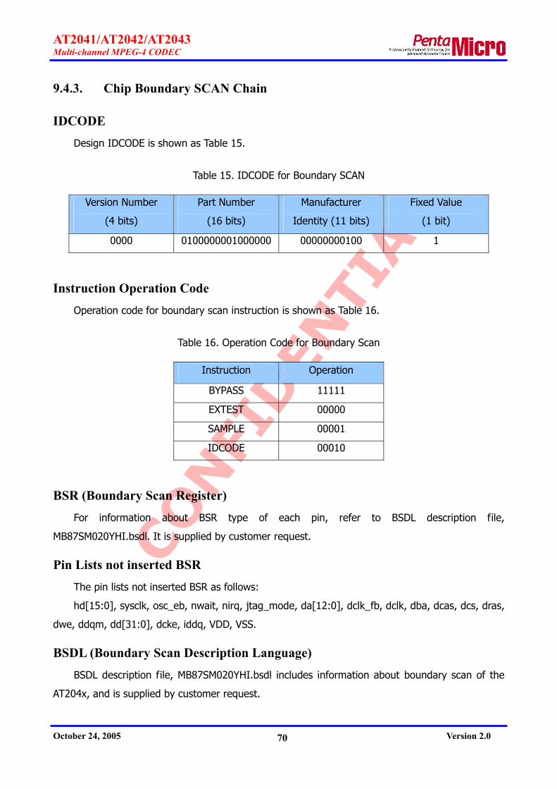
CONFI
DEN
TIAL
AT2041/AT2042/AT2043 Multi-channel MPEG-4 CODEC
October 24, 2005 Version 2.0 70
9.4.3. Chip Boundary SCAN Chain
IDCODE Design IDCODE is shown as Table 15.
Table 15. IDCODE for Boundary SCAN
Version Number
(4 bits)
Part Number
(16 bits)
Manufacturer
Identity (11 bits)
Fixed Value
(1 bit)
0000 0100000001000000 00000000100 1
Instruction Operation Code Operation code for boundary scan instruction is shown as Table 16.
Table 16. Operation Code for Boundary Scan
Instruction Operation
BYPASS 11111
EXTEST 00000
SAMPLE 00001
IDCODE 00010
BSR (Boundary Scan Register) For information about BSR type of each pin, refer to BSDL description file,
MB87SM020YHI.bsdl. It is supplied by customer request.
Pin Lists not inserted BSR The pin lists not inserted BSR as follows:
hd[15:0], sysclk, osc_eb, nwait, nirq, jtag_mode, da[12:0], dclk_fb, dclk, dba, dcas, dcs, dras,
dwe, ddqm, dd[31:0], dcke, iddq, VDD, VSS.
BSDL (Boundary Scan Description Language) BSDL description file, MB87SM020YHI.bsdl includes information about boundary scan of the
AT204x, and is supplied by customer request.

CONFI
DEN
TIAL
AT2041/AT2042/AT2043 Multi-channel MPEG-4 CODEC
October 24, 2005 Version 2.0 71
9.5. MC (Multi-Channel Select)
MC[1:0] pins should be pull-up.

CONFI
DEN
TIAL
AT2041/AT2042/AT2043 Multi-channel MPEG-4 CODEC
October 24, 2005 Version 2.0 72
10. Host Interface Parameters & Messages
10.1. Rx Parameter Interface Protocol
In this chapter, the protocol of host interface is described for parameter setting and chip
control of the AT204x. The host can change the register value and control the AT204x chip by
sending the Rx parameters to Rx FIFO. Rx parameters consist of RxID and RxData. RxID is the
discrimination parameters of RXData and RxData is the value of Rx parameter. And RxID can be
independently used without RxData and several RxData can follow one RxID.
10.1.1. RxID Format
The RxID format is illustrated in the following figure.
15 14 13 12 11 10 9 8 7 6 5 4 3 2 1 0 1 GID CID PID WF
Figure 36. RxID Format
i. GID: Group ID
0: Global, 1: Encoder system, 2: Decoder system, 3: OSD,
4: Encoder video, 5: Encoder video channel,
6: Encoder audio, 7: Encoder audio channel,
8: Decoder video, 9: Decoder video channel,
10: Decoder audio,
ii. CID: Channel ID
iii. PID: Parameter ID
iv. WF: Write Flag
1: Write, 0: Read
The RxID is defined in Rx Parameter Table of section 10.6.
10.1.2. RxData Format
The following is the RxData format.
15 14 13 12 11 10 9 8 7 6 5 4 3 2 1 0 0 Data
Figure 37. RxData Format

CONFI
DEN
TIAL
AT2041/AT2042/AT2043 Multi-channel MPEG-4 CODEC
October 24, 2005 Version 2.0 73
RxData is defined in Rx Parameter Table of section 10.6.
10.1.3. Write
In the case of writing Rx parameter into the AT204x, WF(write flag) of RxID should be set to
1. For more details, please refer to Rx Parameter Table of section 10.6.
For writing global parameters regarding SDRAM configuration in section 10.6.1, the host
should write global parameters first before other parameters are set. Global parameters regarding
SDRAM configuration cannot be written normally after other parameters are set. Refer to section
10.3.3 for global parameter regarding SDRAM configuration.
10.1.4. Read
In the case of reading Rx parameter from the AT204x, WF(write flag) of RxID should be set to
0. Only RxID is used for read operation.
When the AT204x receives read command from the host, it sends out the parameter for RxID
to the host via Tx FIFO. For more details about the read data to Tx FIFO, please refer to 10.2.4
Read data output.
After the host reads data from Tx FIFO, it must send out ‘Ack for Tx’ parameter to the AT204x.
Since not only read data requested by the host but also messages generated in the AT204x are
transmitted through Tx FIFO, programmer should refer to the 10.2.1 TxID Format for reading data.
For reading global parameters regarding SDRAM configuration in section 10.6.1, the host
should read global parameters first before other parameters are set. Global parameters regarding
SDRAM configuration cannot be read normally after other parameters are set. Refer to section
10.3.3 for global parameter regarding SDRAM configuration.
10.2. Tx Message Interface Protocol
This chapter describes how to send the messages and read data generated in the AT204x to
the host. The AT204x delivers the Tx message generated during the operation to the host through
Tx FIFO. And when the host calls for reading of Rx parameter, the AT204x sends out the read data
to the host via Tx FIFO. The AT204x generates interrupt signal (nIRQ) to inform this situation to
the host.
Both of the Tx message and read data consist of the TxID and the TxData. The TxID is the
discrimination parameter for the Tx message or read data. And the TxData is the value of the Tx
message or read data.

CONFI
DEN
TIAL
AT2041/AT2042/AT2043 Multi-channel MPEG-4 CODEC
October 24, 2005 Version 2.0 74
The TxID can be used without the TxData and followed by more than one TxData.
After the host reads Tx message or data from the AT204x, it must send out ‘Ack for Tx’
parameter to the AT204x. Otherwise, the AT204x generates no more Tx messages. If the AT204x
receives ‘Ack for Tx’ parameter, it clears Tx FIFO and then generates next Tx message.
10.2.1. TxID Format
The following is the TxID format.
15 14 13 12 11 10 9 8 7 6 5 4 3 2 1 0 1 GID CID MID MF
Figure 38. TxID Format
v. GID: Group ID
0: Global, 1: Encoder system, 2: Decoder system, 3: OSD,
4: Encoder video, 5: Encoder video channel,
6: Encoder audio, 7: Encoder audio channel,
8: Decoder video, 9: Decoder video channel,
10: Decoder audio,
vi. CID: Channel ID
vii. MID: Message ID
viii. MF: Message Flag
1: Tx message, 0: read data
TxID for Tx message is defined in Tx Message Table of section 10.7.
TxID for Read data is same as RxID defined in Rx Parameter Table of section 10.6.
10.2.2. TxData Format
The following is the TxData format.
15 14 13 12 11 10 9 8 7 6 5 4 3 2 1 0 0 Data
Figure 39. TxData Foramt
TxData is defined in Tx Message Table of section 10.7.
10.2.3. Tx Message output
The Tx message generated from the AT204x, MF(message flag) of the TxID should be 1. For
more details about the TxID and the TxData, please refer to Tx Message Table of section 10.7.

CONFI
DEN
TIAL
AT2041/AT2042/AT2043 Multi-channel MPEG-4 CODEC
October 24, 2005 Version 2.0 75
After the host receives Tx message from the AT204x, it must send out ‘Ack for Tx’ parameter
to the AT204x. Otherwise, the AT204x generates no more Tx messages. If the AT204x receives
‘Ack for Tx’ parameter, it clears Tx FIFO and then generates next Tx message.
10.2.4. Read data output
In case that the host calls for read parameter, MF(message flag) of read parameter requested
by the host requests should be 0. The TxID and the TxData are same as the RxID and the RxData
defined in Rx Parameter Table of section 10.6. After the host reads data from the AT204x, it must
send out ‘Ack for Tx’ parameter to the AT204x. Otherwise, the AT204x generates no more Tx
messages. If the AT204x receives ‘Ack for Tx’ parameter, it clears Tx FIFO and then generates next
Tx message.
10.3. Start-up Sequence
After power ON operation or system reset, the host should interface to the AT204x as
illustrated in the below flowchart.

CONFI
DEN
TIAL
AT2041/AT2042/AT2043 Multi-channel MPEG-4 CODEC
October 24, 2005 Version 2.0 76
Power up
SDRAM scheduler start
F/W + 256bit(0) uploadto DemuxFIFO
SDRAM access enable
Wait for Chip ready message
ROM-less ?
Y
N
A
Ack for Tx message
Global parametersetting
SDRAM Configuration
Figure 40. Start-Up sequence
10.3.1. ROM Boot Sequence
Booting by external SPI serial ROM (rlb/GIO[5] must be pull-down)
When the AT204x is prepared to interface with the host, it sends ‘chip ready message’ to
the host (section 10.7.1).
The AT204x does not generate interrupt signal for ‘chip ready message’ not like other Tx
message. For this reason the host should read ‘chip ready message’ from Tx FIFO after it
checks that Tx FIFO empty flag of status register (section 8.2.1) is zero.
After the host receives ‘chip ready message’, it sends ‘Ack for Tx’ parameter to the AT204x
(section 10.6.1).
10.3.2. ROM-less Boot Sequence
Booting after upload firmware to external SDRAM without external SPI serial ROM ( in this

CONFI
DEN
TIAL
AT2041/AT2042/AT2043 Multi-channel MPEG-4 CODEC
October 24, 2005 Version 2.0 77
case, rlb/GIO[5] is pull-up)
The host writes ‘SDRAM scheduler start’ in command register of the AT204x host interface
unit. (See Command Register of section 8.2.2)
Upload firmware data through demux FIFO of the AT204x.
Upload zero stuffing data more than 256 bit through demux FIFO of the AT204x.
After unloading firmware, the host writes ‘SDRAM access enable’ in command register of
the AT204x host interface unit. (See Command Register of section 8.2.2)
Afterwards, the firmware of the AT2041 will run.
When the AT204x is ready to interface with the host, it sends ‘chip ready message’ to the
host (refer to 10.7.1 section).
The AT204x does not generate interrupt signal for ‘chip ready message’ not like other Tx
message. For this reason the host should read ‘chip ready message’ from Tx FIFO after it
checks that Tx FIFO empty flag of status register (section 8.2.1) is zero.
After the host receives ‘chip ready message’, it sends ‘Ack for Tx’ parameter to the AT204x
(section 10.6.1).
If once firmware is uploaded, firmware cannot be uploaded more again before reset.
For detailed information about Rom-less boot sequence, refer to the AT204x application note,
‘AT204x_AN07_Firmware_Upload_Vxx(Eng).pdf’.
10.3.3. SDRAM Configuration
After boot sequence, global parameters related to SDRAM configuration should be set
according to target application. Refer to section 10.6.1.
SDRAM configuration related global parameters are as follows:
-. Operation Mode (GID=0, CID=0, PID=2)
-. SDRAM Size (GID=0, CID=0, PID=3)
-. Channel Size (GID=0, CID=0, PID=5)
-. Maximum GOPM (GID=0, CID=0, PID=6)
These parameters should be set first after boot sequence, and can be neither changed nor
read after other parameters are set.
The default values of these parameters are based on single channel CODEC using 128 Mbit
SDRAM.
10.3.4. Global Parameter Setting
Other global parameters may be set if needed. Refer to section 10.6.1.

CONFI
DEN
TIAL
AT2041/AT2042/AT2043 Multi-channel MPEG-4 CODEC
October 24, 2005 Version 2.0 78
10.4. Encoding Sequence
For encoding operation, the host will be interfaced to the AT204x as illustrated in the below
flowchart.
Encoder parameter setting
Encoder start
Wait for data ready message
Acknowledge fordata ready message
Stop ?
Encoder stop
Y
N
A
Read stream data from MuxFIFO
Ack for Tx message
Figure 41. Encoding Sequence
If needed, changes encoding parameters.
To start encoding, ‘encoder start’ command should be sent to the AT204x (section 10.6.2).
The host waits for ‘data ready’ message from the AT204x (section 10.7.2).
The host reads encoding data of the size (‘output data size’*256 bits) from Mux FIFO. The
data size is included in ‘data ready’ message (section 10.7.2).
The host sends ‘Ack for Tx’ parameter to the AT204x (section 10.6.1).
To continue encoding, the host should send out ‘acknowledge for data ready’ parameter to
the AT204x (section 10.6.2). Otherwise, the AT204x generates no more ‘data ready’
messages.
To stop encoding, the host should send out ‘encoder stop’ parameter to the AT204x
(section 10.6.2).

CONFI
DEN
TIAL
AT2041/AT2042/AT2043 Multi-channel MPEG-4 CODEC
October 24, 2005 Version 2.0 79
10.5. Decoding Sequence
For decoding operation, host will be interfaced to the AT204x as illustrated in the below
flowchart.
Decoder parameter setting
Decoder start
Wait for data request message
Acknowledge fordata request message
Stop ?
Decoder stop
Y
N
A
Ack for Tx message
Write stream data + 256bit(0)
to DemuxFIFO
Figure 42. Decoding Sequence
If needed, changes decoder parameters.
To start decoding, ‘decoder start’ command is sent to the AT204x (see 10.6.7).
The host waits for ‘data request’ message from the AT204x (see 10.7.7).
After the host receives message, the host writes decoding data to Demux FIFO of the
AT204x.
Write zero stuffing data more than 256 bit to demux FIFO of the AT204x.
The host sends ‘Ack for Tx’ parameter to the AT204x (see 10.6.1).
To continue decoding operation, the host must send out ‘acknowledge for data request’
parameter to the AT204x (see 10.6.7). Otherwise, the AT204x generates no more ‘data
request messages’.
To stop decoding, the host must send out ‘decoder stop’ parameter to the AT204x (see
10.6.7).

CONFI
DEN
TIAL
AT2041/AT2042/AT2043 Multi-channel MPEG-4 CODEC
October 24, 2005 Version 2.0 80
10.6. Rx Parameter Table
The meaning of each item is as follows:
GID, CID, PID, RW
The component of RxID (Refer to 10.6 section)
RW
R: read only, W: write, RW: read & write
C
O: possible to change parameter during encoding or decoding
X: impossible to change parameter during encoding or decoding
Num. of RxData
the number of RxData parameter after RxID
#
order of RxData
Pos.
Bit position
Def.
Default value
ex.1) ‘ack for Tx’ parameter to the AT204x after receiving Tx message
In this example, GID value is 0x0, CID value is 0x0, PID value is 0x1 and it is write only mode,
so the RxID value should be 0x8003. The RxData is not transferred because the ‘Num. of RxData’
value is 0.
ex.2) ‘Encoder Start’ parameter
In this example, GID value is 0x1, CID value is 0x0, PID value is 0x2. So the RxID value is
0x8805. Only one RxData should be transferred because the ‘Num. of RxData’ value is 1. For
encoding only video the RxData is 0x1, and for encoding audio and video together the RxData
is 0x3.
For reading parameter the host sets WF field to 0 and transfers only RxID. In this case the
RxID value is 0x8802. When the AT204x receives reading command, it sends the RxData with
the RxID to host using Tx FIFO.
The parameter among below table, which color is gray, is not available yet.

CONFI
DEN
TIAL
AT2041/AT2042/AT2043 Multi-channel MPEG-4 CODEC
October 24, 2005 Version 2.0 81
10.6.1. Global Parameters
GID = 0, CID = 0
Num. of RxData Name PID RW C
# Pos. Def. Field Description Note
0x01 W O 0 Ack for Tx After receiving this parameter, the AT204x clears it’s Tx FIFO and generates the next Tx message.
1 Operation mode (Refer to Section 10.3.3) 0x02 RW X
0 2:0 2 0: forbidden, 1: Encoder, 2: CODEC
1 SDRAM size (Refer to Section 10.3.3) 0x03 RW X
0 10:0 128 64~1024(Mbit)
…
1 Channel size (Refer to Section 10.3.3) 0x05 RW X
0 4:0 1 1~16
1 Maximum GOPM (Refer to Section 10.3.3) 0x06 RW X
0 1:0 3 1~3
…
1 Host interface signal control
0 1 Wait (nWAIT/READY) active pull-up or pull-down 1: active mode (fast) 0: normal mode (slow)
1 0 Wait (nWAIT/READY) polarity inverse 0: default polarity (refer to Table 14) 1: inverse polarity
0x10 W X
0
2 0 Interrupt (nIRQ/INT) polarity inverse 0: default polarity (refer to Table 14) 1: inverse polarity
0x11 W X 0 Sleep mode AT204X goes to sleep mode. Any Rx parameter can wake the AT204X from sleep mode
1 GIO Mode
0x12 RW X 0 7:0 0
0: user control mode 1: debug mode 2: GIO channel ID interface mode
1
GIO Direction This is valid when ‘GIO mode’ = 0 Dir[7:0] controls the direction of GIO[15:8] ports. If dir[n] = 0, GIO[8+n] port is input. If dir[n] = 1, GIO[8+n] port is output. (n = 0 ~ 7)
0x13 RW X
0 7:0 0 Dir[7:0]

CONFI
DEN
TIAL
AT2041/AT2042/AT2043 Multi-channel MPEG-4 CODEC
October 24, 2005 Version 2.0 82
Num. of RxData Name PID RW C
# Pos. Def. Field Description Note
2
GIO Data This is valid when ‘GIO mode’ = 0 Write: If mask[n] = 1, data[n] will be output to GIO[8+n] port. If mask[n] = 0, the output of GIO[8+n] port will not be changed. Read: data[7:0] is the value of GIO[15:8] ports. Mask[7:0] will be read by 0xFF. (n = 0 ~ 7)
0 7:0 . Data[7:0]
0x14 RW O
1 7:0 . Mask[7:0] …
1 Operation Mode 2
0x20 RW X 0 0 0
0: normal mode 1: transcoding mode
(Only if operation mode is CODEC) 2: 2-way encoding mode
4 Global status
0 .
Data ready status 0: state that 'data ready message' is not output yet 1: state that 'data ready message' is already output,
and waiting for ack.
1 .
Data request status 0: state that 'data request message' is not output
yet 1: state that 'data request message' is already
output, and waiting for ack.
0
2 . Reserved 1 0 . Reserved 2 0 . Reserved
0x30 R .
3 0 . Reserved
10.6.2. Encoder System Parameters
GID = 1, CID = 0
Num. of RxData Name PID RW C
# Pos. Def. Field Description Note
0x01 W O 0
Acknowledge for data ready message Obsolete. This can be replaced by 'Alt. ack. for data ready message' (GID=1, PID=0x30). This can be used only if 'Encoder acknowledge mode' = 0 (GID=1,PID=0x31).

CONFI
DEN
TIAL
AT2041/AT2042/AT2043 Multi-channel MPEG-4 CODEC
October 24, 2005 Version 2.0 83
Num. of RxData Name PID RW C
# Pos. Def. Field Description Note
1 Encoder start
0 0
Video encoder start. When write,
1: start, 0: no operation When read,
it means current video encoder state. 1: run, 0: stop
0x02 RW X 0
1 0
Audio encoder start. When write,
1: start, 0: no operation When read,
it means current audio encoder state. 1: run, 0: stop
1 Encoder stop
0 . Video encoder stop 1: stop, 0: no operation 0x03 W O
0 1 . Audio encoder stop
1: stop, 0: no operation
1 Output stream format
0x04 RW X 0 1:0 2
0: reserved 1: reserved 2: PES (Packetized Elementary Stream) 3: TS (Transport Stream)
1 Maximum output data size
0x05 RW X 0 14:0 512
Maximum data size (KByte unit, min=8). If the output data size is bigger than this size, it will be split into more than one part. The last part is indicated by the ‘last flag’, that is in the ‘data ready message’.
…
2
Alternate acknowledge for data ready message This can be used only if 'Encoder acknowledge mode' = 1 (GID=1,PID=0x31).
0 0 0
Null flag 0: normal ack (same as ‘ack. for data ready
message’ [GID=1,PID=1]) 1: null ack, re-issue data ready message for current
data after about 10msec
0x30 W O
1 0 0 Reserved
1 Encoder acknowledge mode 0x31 RW X
0 0 0 0: use default 'data ready ack [GID=0,PID=1]' 1: use 'alter. data ready ack [GID=0,PID=0x30]'

CONFI
DEN
TIAL
AT2041/AT2042/AT2043 Multi-channel MPEG-4 CODEC
October 24, 2005 Version 2.0 84
10.6.3. Encoder Video Parameters
GID = 4, CID = 0
Num. of RxData Name NotePID RW C
# Pos. Def. Field Description
4 Input video format 0 9:0 720 Horizontal size. 32~720 1 9:0 480 Vertical size. 16~576
2 3:0 4
Video input rate code. 0: forbidden, 1: 24000/1001, 2: 24, 3 : 25, 4: 30000/1001, 5: 30, 6: 50, 7: 60000/1001, 8: 60, 9: 100, 10: 120000/1001, 11: 120
0x01 RW X
3 0 0 Field mode.
1: field mode input (progressive) 0: frame mode input (interlaced)
1 Input video clock inversion 0x02 RW X
0 0 0 0: use input clock 1: use inverted input clock
1 Input video sync mode
0x03 RW X 0 1:0 2
0: normal embedded sync mode 1: BT embedded sync mode
Regards the data of ‘0x00’ as invalid data. 2: external sync mode
1 Vertical offset mode
0x04 RW X 0 0 1
This is valid only if input video sync mode = 0. 1: use the following offset 0: don’t care the following offset
2
Vertical offset value These are valid only if vertical offset mode = 1. The offset from FSYNC transition line to the start line of valid data.
0 4:0 19 Vertical offset for even field (min = 19)
0x05 RW X
1 4:0 18 Vertical offset for odd field (min = 18)
1 Field sync mode
0x06 RW X 0 0 0
0: use the input field sync. 1: generate field sync using the ‘first field decision
parameter’.

CONFI
DEN
TIAL
AT2041/AT2042/AT2043 Multi-channel MPEG-4 CODEC
October 24, 2005 Version 2.0 85
Num. of RxData Name NotePID RW C
# Pos. Def. Field Description
1 First field decision parameter
0x07 RW X 0 8:0 128
This is valid only if the field sync mode = 1. If the number of clock cycles between the start of vertical sync and the start of horizontal sync is less than or equal this value, the next field is the first field.
1 Video input sync polarity
0 1 Horizontal valid polarity 1: active high, 0: active low
1 1 Horizontal sync polarity 1: active high, 0: active low
2 1 Vertical valid polarity 1: active high, 0: active low
3 1 Vertical sync polarity 1: active high, 0: active low
0x08 RW X 0
4 0 Field sync value of the first field
4 Input video data saturation value 0 7:0 16 Minimum value of luminance data 1 7:0 235 Maximum value of luminance data 2 7:0 16 Minimum value of chrominance data
0x09 RW X
3 7:0 239 Maximum value of chrominance data
1 Preprocessing filter control
0 1 Low pass filter 0: off, 1: on 0x0A RW O
0 1 1 Median filter
0: off, 1: on
1 Input video shift-right size Shift-right input video data. Filled by garbage data.
0x0B RW X 0 1:0 0 Shift-right pixel size = (this value * 4) pixels
1 Channel ID interface mode 0x0C RW X
0 8 0 Timing mode 0: current mode 1: next mode

CONFI
DEN
TIAL
AT2041/AT2042/AT2043 Multi-channel MPEG-4 CODEC
October 24, 2005 Version 2.0 86
Num. of RxData Name NotePID RW C
# Pos. Def. Field Description
7:0 0
Interface mode 0: single channel encoding (channel ID = 0) 1: AT4012E VBI interface mode 2: AT4013E VBI interface mode (single chip mode) 3: AT4013E VBI (master in 2-chip mode) 4~31: Reserved 32: general VBI interface mode 1 33: general VBI interface mode 2 34: general VBI interface mode 3 35: general VBI interface mode 4 36~63: Reserved 64: custom mode 1 (IVR-LF16 of IVNET) 65: custom mode 2 (NVC1401 of NEXTCHIP) 66: custom mode 3 (AM7416 of ALOGIC) 67: custom mode 4 (IVR-FS1648 of IVNET) 68: custom mode 5 (NVC1001 of NEXTCHIP) 69: custom mode 6 (AM524M of ALOGIC) 70: custom mode 7 (TW2834 of TECHWELL) 71: custom mode 8 (TW2834 with ANAPATH) 72~127: Reserved 128: GIO channel ID interface mode 1 129: GIO channel ID interface mode 2 130: GIO channel ID interface mode 3 131: GIO channel ID interface mode 4 132~239: Reserved 240~255: Test mode
1 Watermark enable 0x0D RW X
0 0 0 1: enable, 0: disable
1 Watermark strength 0x0E RW X
0 2:0 0 0~4
16 Watermark key 0x0F RW X
N 7:0 0x00 N = 0 ~ 15 …
1 Reference picture selection 0x11 RW X
0 0 0 0: Last I/P-picture reference mode (ISO standard) 1: Last I-picture reference mode (non ISO standard)
…
1 Dummy channel ID
0x14 RW X 0 4:0
0xF or
0x10
Dummy physical channel ID, 0 ~ 16 Frames (or Fields) of dummy channel ID are not encoded but discarded. The value 16 means that there is not dummy channel. If ‘channel ID interface mode’ <= 3, default value is 0xF else default value is 0x10
1 Motion detection information output mode 0x15 RW X
0 0 0 0: off 1: on

CONFI
DEN
TIAL
AT2041/AT2042/AT2043 Multi-channel MPEG-4 CODEC
October 24, 2005 Version 2.0 87
Num. of RxData Name NotePID RW C
# Pos. Def. Field Description 1 Encoding offset mode
0x16 RW X 0 0 0 0: fixed offset mode
1: dynamic offset mode
2 1st dynamic offset value
0 5:0 0 1st horizontal offset (16-pel unit) 0x17 RW X
1 8:0 0 1st vertical offset (2-pel unit) 2 2nd dynamic offset value
0 5:0 23 2nd horizontal offset (16-pel unit) 0x18 RW X
1 8:0 0 2nd vertical offset (2-pel unit)
2 3rd dynamic offset value 0 5:0 0 3rd horizontal offset (16-pel unit) 0x19 RW X
1 8:0 240 3rd vertical offset (2-pel unit) 2 4th dynamic offset value
0 5:0 23 4th horizontal offset (16-pel unit) 0x1A RW X
1 8:0 240 4th vertical offset (2-pel unit)
1 Recording frame rate control mode
0x1B RW X 0 0 0
Mode 0: use recording frame rate control mode 0
(GID=0x5,PID=0x24) 1: use recording frame rate control mode 1 (GID=0x5,PID=0x28)
…
3 Time code 0 4:0 0 Hour 1 5:0 0 Minute
0x20 RW O
2 5:0 0 Second …
2 Q range in CBR mode 0 4:0 1 Qmin 0x25 RW O
1 4:0 31 Qmax
10.6.4. Encoder Video Channel Parameters
GID = 5, CID = Logical Channel ID
Num. of RxData Name PID RW C
# Pos. Def. Field Description Note
1 Pause & Restart 0x01 RW O
0 0 1 0: pause, 1: restart
…
1 Encoding standard 0x03 RW X
0 2:0 4 0: JPEG, 1: MPEG1, 2: MPEG2, 3: H.263, 4: MPEG4

CONFI
DEN
TIAL
AT2041/AT2042/AT2043 Multi-channel MPEG-4 CODEC
October 24, 2005 Version 2.0 88
Num. of RxData Name PID RW C
# Pos. Def. Field Description Note
1 Rate control mode
0x04 RW X 0 1:0 0
0: Fixed Q – Q is quality parameter. 1: Picture level rate control (CBR) 2: MB level rate control (CBR) * JPEG supports only fixed Q mode * AT204X doesn’t control vbv_buffer fullness.
1 Q value (image quality for JPEG)
0x05 RW O 0 6:0 5
JPEG: 1~100 (%) Other standards: 1~31 (Q value) * This is valid only if the rate control mode is ‘0’
1 Rate control parameters
0x06 RW O 0 9:0 100
Average bit rate per frame (1000-bit unit), 1~1023 This is valid only if the rate control mode is not ‘0’
3 GOP structure
0 1:0 1
GOP structure mode 0: Open GOP 1: Closed GOP ( I B P B P … ) 2: Closed GOP type 2 ( I P B P … )
1 7:0 10 GOP_NM(=N/M), 1~ 255
0x07 RW O
2 1:0 1 GOP_M (=M), 1~3
0x08 RW O 0 Force I Insert I-frame by force
1 Re-sync mode It is valid for JPEG, H.263 and MPEG-4
0x09 RW X 0 1:0 0
0: re-sync off 1: re-sync interval mode (MPEG-4 only) 2: slice re-sync mode
1 Re-sync interval
0x0A RW X 0 14:0 512
Re-sync interval byte size (2-byte unit) Min = 64 (128bytes) This is valid only if re-sync mode = 1 (MPEG-4 only)
1 MPEG encoding parameters
1:0 0 Intra_dc_precision (MPEG2) 0: 8-bit, 1: 9-bit, 2: 10-bit, 3: 11-bit
2 0 Q_scale_type (MPEG2) 0: linear, 1: non-linear
3 0 Intra_vlc_format (MPEG2) Refer to ISO/IEC13818-2
4 0 Alternate_scan (MPEG2/4) 0: zigzag scan, 1: alternate scan
0x0B RW X
0
5 0 Vop_rounding_type (MPEG4) Refer to ISO/IEC14496-2

CONFI
DEN
TIAL
AT2041/AT2042/AT2043 Multi-channel MPEG-4 CODEC
October 24, 2005 Version 2.0 89
Num. of RxData Name PID RW C
# Pos. Def. Field Description Note
8:6 0 Intra_dc_vlc_thr (MPEG4) 0 ~ 7 Refer to ISO/IEC14496-2
9 0 Quant_type (MPEG4) Refer to ISO/IEC14496-2
10 0 Direct mode (MPEG4) 0: off, 1: on
11 0 4MV mode (MPEG4) 0: off, 1: on
13 0
Simple profile (MPEG4) 0: off, 1: on Simple profile does not supports both interlace tool and B-VOP.
14 0 Adaptive quantization 0: off, 1: on
2 Reaction parameter in CBR mode React = (React_a + 1)/(React_b + 1)
0 3:0 0 React_a 0xC RW X
1 3:0 0 React_b
…
1 Encoding video stream_id
0x1F RW X 0 3:0 CID
stream_id, 0~15 The stream_id of PES packet header is output as (0xE0 + stream_id). If encoding standard is JPEG, the stream_id of PES packet header is output as (0xD0 + stream_id).
1 Physical Channel ID assign 0x20 RW X
0 3:0 CID Physical channel ID, 0~15
1 Video Loss 0x21 RW O
0 0 0 0: normal record 1: not record (loss)
2 Input video scale mode * In this case, CID means Physical channel ID
0 2:0 0 Horizontal scale mode 0: 1, 1: 8/9, 2: 1/2, 3: 4/9 0x22 RW O
1 0 0 Vertical scale mode 0: 1, 1: 1/2
4 Encoding region information 0 5:0 0 Horizontal offset (16-pel unit) 1 8:0 0 Vertical offset (2-line unit) 2 5:0 45 Horizontal MB size (16-pel unit)
0x23 RW O
3 5:0 30 Vertical MB size (16-line unit)

CONFI
DEN
TIAL
AT2041/AT2042/AT2043 Multi-channel MPEG-4 CODEC
October 24, 2005 Version 2.0 90
Num. of RxData Name PID RW C
# Pos. Def. Field Description Note
2 Recording frame rate control mode 0
0 7:0 1 Frame_rate_in The number of input frames 1~255
0x24 RW O
1 7:0 1
Frame_rate_out The number of frames to be recorded out of the input frames. 0~ ‘Number of input frame’
1 Motion-less frame recording mode 0x25 RW O
0 0 0 0: normal record, 1: not record (skip)
5 Motion detection parameters
0 2:0 2 Sensitivity 0(more sensitive)~7 (less sensitive)
1 5:0 32 Pixel difference threshold 1~63
2 6:0 32 Different pixel count threshold 1~127
3 7:0 5 Motion MB count threshold 1~255
0x26 RW X
4 7:0 5 Motion-less frame count threshold 1~255
54 Motion detection area bitmap
0x27 RW X N 7:0 0xFF
N = 0 ~ 53 1 bit is assigned to 2x2MBs and 3 bytes are assigned to 2 slices. The MS bit of the first byte is aligned to the left-top 2x2MBs of the input video
3 Recording frame rate control mode 1 0 4:0 1 Table_depth (1~30) 1 14:0 1 Table_data[14:0]
0x28 RW O
2 14:0 0 Table_data[29:15] …
2 Scale mode for 2-way encoding In this case, CID means physical channel ID
0 2:0 1 Horizontal scale-down mode 0: 1, 1: 1/2, 2: 1/3, 3: 1/4, 4: 2/3 0x30 RW O
1 2:0 1 Vertical scale-down mode 0: 1, 1: 1/2, 2: 1/3, 3: 1/4, 4: 2/3

CONFI
DEN
TIAL
AT2041/AT2042/AT2043 Multi-channel MPEG-4 CODEC
October 24, 2005 Version 2.0 91
10.6.5. Encoder Audio Parameters
GID = 6, CID = 0
Num. of RxData Name PID RW C
# Pos. Def. Field Description Note
1 Audio encoding standard
0x01 RW X 0 3:0 1
0: u-Law PCM 1: ADPCM 2: MPEG-1 Layer 2 9: ADPCM stereo 10: ADPCM mono (Left channel) 11: ADPCM mono (Right channel)
…
3 Audio input format
0 2:0 2
Audio input format 0: I2S mode 1: left justified mode 2: u-Law PCM mode 3: a-Law PCM mode 4: linear PCM mode
1 2:0 4
Bit width of input data 0: 8-bit, 1: 16-bit, 4: 32-bit, 5: 64-bit, 6: 128-bit
For a-Law & u-Law PCM input format Channel_size * 8-bit
For linear PCM input format Channel_size * 16-bit
For other input format Bit width of input data per mono channel
0x03 RW X
2 1:0 0 Delay mode 0: no delay, 1: 1 bit delay
1 Audio clock inversion 0x04 RW X
0 0 1 0: use input clock, 1: use inverted clock
… 1 Audio output packet size
0x10 RW X 0 4:0 11
Output packet size M = 2^N (unit: byte) Where, N= 8 ~ 12 Output packet size does not include the size of PES packet header and ADPCM header.
…
3 MPEG1 layer2 audio encoding parameters
0 0 0 Stereo 0=mono, 1=stereo
1 0 0 Sampling rate (KHz) 0=44.1, 1=48, 2=32, 3:reserved 0x12 RW X
2 0 0
Bit rate (Kbps) 1: 32, 2: 48, 3: 56, 4: 64, 5: 80, 6: 96, 7: 112, 8: 128, 9: 160, 10: 192, 11: 224, 12: 256, 13: 320, 14: 384

CONFI
DEN
TIAL
AT2041/AT2042/AT2043 Multi-channel MPEG-4 CODEC
October 24, 2005 Version 2.0 92
10.6.6. Encoder Audio Channel Parameters
GID = 7, CID = Logical Channel ID
Num. of RxData Name PID RW C
# Pos. Def. Field Description Note
1 On/off (restart/pause) 0x01 RW O
0 0 1 1: on (restart) 0: off (pause)
…
1 Physical Channel ID assign 0x03 RW X
0 3:0 CID Physical channel ID, 0~15
1 Encoding audio stream_id
0x04 RW X 0 3:0 CID
stream_id, 0~15 The stream_id of PES packet header is output as (0xC0 + stream_id).
10.6.7. Decoder System Parameters
GID = 2, CID = 0
Num. of RxData Name PID RW C
# Pos. Def. Field Description Note
0x01 W O 0
Acknowledge for data request message Obsolete. This can be replaced by 'Alt. ack. for data request message' (GID=2,PID=0x30).
1 Decoder Start
0 0
Video decoder start. When write,
1: start, 0: no operation When read,
it means current video decoder state. 1: run, 0: stop
0x02 RW X 0
1 0
Audio decoder start. When write,
1: start, 0: no operation When read,
it means current audio decoder state. 1: run, 0: stop
1 Decoder Stop
0 . Video decoder stop 1: stop, 0: no operation 0x03 W O
0 1 . Audio decoder stop
1: stop, 0: no operation
…

CONFI
DEN
TIAL
AT2041/AT2042/AT2043 Multi-channel MPEG-4 CODEC
October 24, 2005 Version 2.0 93
Num. of RxData Name PID RW C
# Pos. Def. Field Description Note
1 Input stream format
0x06 RW X 0 1:0 2
0: reserved 1: PS 2: PES (Packetized Elementary Stream) 3: TS (Transport Stream)
1 Sync lock counting number 0x07 RW X
0 2:0 3 0 ~ 7 This is valid only if the input stream format is TS.
…
3 Demux control parameters for video This is valid if the input stream format is TS or PS.
0 0 . Reserved 1 12:0 0xE0 Video target PID
0x0C RW X
2 0 . Reserved …
3 Demux control parameters for audio This is valid if the input stream format is TS or PS.
0 0 . Reserved 1 12:0 0xC0 Audio target PID
0x0E RW X
2 0 . Reserved
…
1 Decoding mode (Trick Mode)
9:8 0
Decoding mode[1:0] 0 : normal mode (decoding with time stamp) 1 : skip mode
if (DTS-STC) is greater than the given time, AT204x does not wait for (DTS-STC) seconds but set DTS to STC
2 : non-realtime mode
7:5 0
Trick mode[2:0] 0 : play 1 : fast 2 : slow 3 : step 4 : pause
4 0 Direction
0: forward 1: backward
0x10 RW O 0
3:0 0
Speed[3:0] If trick mode = fast, (2^speed) If trick mode = slow, 1/(2^speed)

CONFI
DEN
TIAL
AT2041/AT2042/AT2043 Multi-channel MPEG-4 CODEC
October 24, 2005 Version 2.0 94
Num. of RxData Name PID RW C
# Pos. Def. Field Description Note
1 Decoder buffer flush This have to be used only in pause mode
0 0
Video flush mode for write 0: clear output video when flushing 1: maintain output video when flushing
Video flush status for read 0: finished 1: under flush
0x11 RW O
0
1 0
Reserved for write Audio flush status for read
0: finished 1: under flush
…
2 Lip sync control 0 3:0 0 Audio delay, 0 ~ 10 (unit: 100 msec.) 0x12 RW X
1 3:0 0 Video delay, 0 ~ 10 (unit: 100 msec.)
4 Output video time stamp 0 14:0 . PTS[18:4]
13:0 . PTS[32:19] 1
14 . PTS invalid flag The PTS is valid only if PTS_invalid_flag is 0.
2 14:0 . DTS[18:4] 13:0 . DTS[32:19]
0x13 R .
3 14 . DTS invalid flag
The DTS is valid only if DTS_invalid_flag is 0.
4 Output audio time stamp 0 14:0 . PTS[18:4]
13:0 . PTS[32:19] 1
14 . PTS invalid flag The PTS is valid only if PTS_invalid_flag is 0.
2 14:0 . DTS[18:4] 13:0 . DTS[32:19]
0x14 R .
3 14 . DTS invalid flag
The DTS is valid only if DTS_invalid_flag is 0.
1 Decoder STC speed control 0x15 RW O
0 7:0 0 Speed (signed, 2’s complement) -15~15
1 Time interval for skip mode 0x16 RW O
0 7:0 5 Time interval (sec) 2 Depth of input stream buffers
0 4:0 9 video: video stream buffer depth (frame) 0x17 RW X
1 4:0 19 audio: audio stream buffer depth (PES packet)

CONFI
DEN
TIAL
AT2041/AT2042/AT2043 Multi-channel MPEG-4 CODEC
October 24, 2005 Version 2.0 95
Num. of RxData Name PID RW C
# Pos. Def. Field Description Note
2 Decoder STC value 0 14:0 . STC[18:4] 0x18 R .
1 13:0 . STC[32:19]
…
2 Alt. ack. for data request message
11:2 . Decoding mode for the current input data. This value must be the same as decoding mode value (GID=2, CID=0, PID = 0x10).
0
1:0 .
Ack_mode (refer to section 11.12) 0: continue 1: last. This can replace 'Acknowledge for
data request message' (GID=2,PID=0x1). 2: null. re-issue data request message after about
10msec
0 .
Discontinuity 0: no discontinuity 1: set discontinuity now
The STC(system time clock) is initialized and the AT204x decodes with next I-Picture for all channel.
1 . Frame pause flag for video. If this flag is ‘1’, the trick mode becomes ‘PAUSE’ after displaying this frame.
0x30 W O
1
2 . Display off flag for video. 0: decoding and display the frame 1: decoding but not display the frame
10.6.8. Decoder Video Parameters
GID = 8, CID = 0
Num. of RxData Name PID RW C
# Pos. Def. Field Description Note
1 Output video format 0x01 RW X
0 1:0 0 0: NTSC, 1: PAL
1 Output video clock inversion 0x02 RW X
0 0 0 0: use input clock 1: use inverted input clock
1 Slave mode 0x03 RW X
0 0 0 0: sync master mode, 1: sync slave mode
2 Vertical offset The offset from 1st line to the start line of valid data
0 9:0 284 Vertical offset for even field 0x04 RW X
1 9:0 21 Vertical offset for odd field

CONFI
DEN
TIAL
AT2041/AT2042/AT2043 Multi-channel MPEG-4 CODEC
October 24, 2005 Version 2.0 96
Num. of RxData Name PID RW C
# Pos. Def. Field Description Note
1 Field sync mode
0x05 RW X 0 0 0
This is valid only if slave mode = 1 0: use field sync input 1: generate field sync using the ‘first field
decision parameter’
1 First field decision parameter
0x06 RW X 1 7:0 128
This is valid only if the field sync mode = 1. If the number of clock cycles between the start of vertical sync and the start of horizontal sync is less than or equal this value, the next field is the first field.
3 Horizontal sync control This is valid only if slave mode = 0.
0 10:0 32 Horizontal sync start position 1 10:0 160 Horizontal sync end position
0x07 RW X
2 10:0 1440 Hsync to hvalid end cycles
6 Vertical sync control 0 9:0 3 Vertical sync start line number of the first field 1 9:0 7 Vertical sync end line number of the first field
2 10:0 90
Vertical sync transition position of the first field. This value means the offset cycles from the end of horizontal valid to the vertical sync transition position.
3 9:0 265 Vertical sync start line number of the second field 4 9:0 268 Vertical sync end line number of the second field
0x08 RW X
5 10:0 855 Vertical sync transition position of the second field.
3 Field sync control 0 9:0 3 First field start line number 1 9:0 265 Second field start line number
0x09 RW X
2 10:0 31
Field sync transition position. This value means the offset cycles from the end of horizontal valid to the field sync transition position.
1 Video output sync polarity
0 1 Horizontal valid polarity 1: active high, 0: active low
1 0 Horizontal sync polarity 1: active high, 0: active low
2 1 Vertical valid polarity 1: active high, 0: active low
3 0 Vertical sync polarity 1: active high, 0: active low
0x0A RW X 0
4 0 Field sync value of the first field
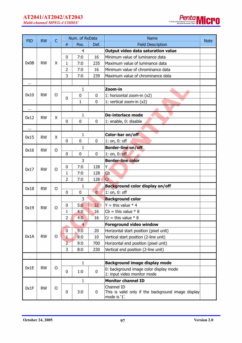
CONFI
DEN
TIAL
AT2041/AT2042/AT2043 Multi-channel MPEG-4 CODEC
October 24, 2005 Version 2.0 97
Num. of RxData Name PID RW C
# Pos. Def. Field Description Note
4 Output video data saturation value 0 7:0 16 Minimum value of luminance data 1 7:0 235 Maximum value of luminance data 2 7:0 16 Minimum value of chrominance data
0x0B RW X
3 7:0 239 Maximum value of chrominance data
…
1 Zoom-in 0 0 1: horizontal zoom-in (x2) 0x10 RW O
0 1 0 1: vertical zoom-in (x2)
…
1 De-interlace mode 0x12 RW X
0 0 0 1: enable, 0: disable
…
1 Color-bar on/off 0x15 RW X
0 0 0 1: on, 0: off
1 Border-line on/off 0x16 RW O
0 0 0 1: on, 0: off
3 Border-line color 0 7:0 128 Y 1 7:0 128 Cb
0x17 RW O
2 7:0 128 Cr
1 Background color display on/off 0x18 RW O
0 0 0 1: on, 0: off
3 Background color 0 5:0 32 Y = this value * 4 1 4:0 16 Cb = this value * 8
0x19 RW O
2 4:0 16 Cr = this value * 8
4 Foreground video window 0 9:0 20 Horizontal start position (pixel unit) 1 8:0 10 Vertical start position (2-line unit) 2 9:0 700 Horizontal end position (pixel unit)
0x1A RW O
3 8:0 230 Vertical end position (2-line unit)
…
1 Background image display mode 0x1E RW O
0 1:0 0 0: background image color display mode 1: input video monitor mode
1 Monitor channel ID
0x1F RW O 0 3:0 0
Channel ID This is valid only if the background image display mode is ‘1’.

CONFI
DEN
TIAL
AT2041/AT2042/AT2043 Multi-channel MPEG-4 CODEC
October 24, 2005 Version 2.0 98
Num. of RxData Name PID RW C
# Pos. Def. Field Description Note
3 Background image color This is valid only if the background image display mode is ‘0’.
0 7:0 28 Y 1 7:0 212 Cb
0x20 RW X
2 7:0 120 Cr
…
0x22 W O 0
Apply next param The 'apply next param' parameter should be set after 'next display offset' parameter [GID=9, PID= 0x12] and 'next display mode' parameter [GID=9, PID=0x14] are set.
1 Horizontal 16-pel align mode
0x23 RW X 0 0 0
0: 32-pel align mode. 1: 16-pel align mode. This value has to be used with the chip of which LOT is 0511 or later.
1 Reference picture selection 0x24 RW X
0 0 0 0: Last I/P-picture reference mode (standard) 1: Last I-picture reference mode (non-standard)
1 Pre-decoding display mode 0x25 RW X
0 0 0 0: display the last decoded picture 1: display the background image color
1 Low delay display mode 0x26 RW X
0 0 0 0: There is frame delay from decoding to display. 1: There is no frame delay from decoding to display.
10.6.9. Decoder Video Channel Parameters
GID = 9, CID = Channel ID
Num. of RxData Name PID RW C
# Pos. Def. Field Description Note
1 Decoding standard 0x01 RW X
0 2:0 4 0: JPEG, 1: MPEG1, 2: MPEG2, 3: H.263, 4: MPEG4
1 Freeze 0x03 RW O
0 0 0 1: on, 0: off
1 Display 0x04 RW O
0 0 0 1: on, 0: off 0x05 W O 1 Display priority

CONFI
DEN
TIAL
AT2041/AT2042/AT2043 Multi-channel MPEG-4 CODEC
October 24, 2005 Version 2.0 99
Num. of RxData Name PID RW C
# Pos. Def. Field Description Note
0 2:0 .
Write 1: move top 2: move up 3: move down 4: move bottom
Read Current priority (0[top] ~ 15[bottom])
1 Decoding stream_id 0x06 RW X
0 3:0 CID stream_id, 0~15
…
2 Scale-down mode
0 2:0 0 Horizontal scale-down mode 0: 1, 1: 1/2, 2: 1/3, 3: 1/4, 4: 2/3 0x10 RW O
1 2:0 0 Vertical scale-down mode 0: 1, 1: 1/2, 2: 1/3, 3: 1/4, 4: 2/3
2 Display offset 0 5:0 0 Horizontal offset (16-pel unit) 0x11 RW O
1 5:0 0 Vertical offset (16-line unit)
2 Next Display offset 0 5:0 0 Horizontal offset (16-pel unit) 0x12 RW O
1 5:0 0 Vertical offset (16-line unit)
See also
GID=8
PID=0x22
1
Display mode Automatic zoom & scale control See Table 17 for relationship between display mode and zoom/scale-down factor.
3:0 0 Display mode A 0:Org, 1:Full_D1, 2:2/3, 3:1/2, 4:1/3, 5:1/4
7:4 0 Display mode B 0:Org, 1:Full_D1, 2:2/3, 3:1/2, 4:1/3, 5:1/4
0x13 RW O
0
8 0
HV_flag 0: Horizontal display mode = Display mode A
Vertical display mode = Display mode A 1: Horizontal display mode = Display mode A
Vertical display mode = Display mode B
1 Next Display mode
3:0 0 Display mode A 0:Org, 1:Full_D1, 2:2/3, 3:1/2, 4:1/3, 5:1/4
7:4 0 Display mode B 0:Org, 1:Full_D1, 2:2/3, 3:1/2, 4:1/3, 5:1/4 0x14 RW O
0
8 0
HV_flag 0: Horizontal display mode = Display mode A
Vertical display mode = Display mode A 1: Horizontal display mode = Display mode A
Vertical display mode = Display mode B
See also
GID=8
PID=0x22
…

CONFI
DEN
TIAL
AT2041/AT2042/AT2043 Multi-channel MPEG-4 CODEC
October 24, 2005 Version 2.0 100
Num. of RxData Name PID RW C
# Pos. Def. Field Description Note
1
Frame display time It means the time that a frame to be displayed when there is no more frame to be displayed for a while.
0x17 RW O
0 7:0 0
0: display the last frame forever. 1~255: display the last frame for this time (100msec unit) and display the background image color.
1 EQ on/off 0x20 RW O
0 0 0 1: on, 0: off
2 EQ parameters This is valid only if EQ is on
0 1:0 2 EQ strength, 0(weak)~3(strong) 0x21 RW O
1 1:0 0 IIR strength, 0(weak)~3(strong)
1 Enhancement on/off 0x22 RW O
0 0 0 1: on, 0: off
1 Brightness 0x23 RW O
0 7:0 128 DC offset value = (this value - 128) …
4 Output video channel time stamp
0 14:0 . PTS[18:4]
13:0 . PTS[32:19] 1
14 . PTS invalid flag The PTS is valid only if PTS_invalid_flag is 0.
2 14:0 . DTS[18:4] 13:0 . DTS[32:19]
0x30 R .
3 14 . DTS invalid flag
The DTS is valid only if DTS_invalid_flag is 0.
Table 17. The relationship between display mode and zoom/scale-down factor
Display mode Original video resolution
0: Org. 1: Full_D1 2: 2/3 3: 1/2 4: 1/3 5: 1/4
H>360, V>288 Manual 1 2/3 1/2 1/3 1/4
H>240, V>192 Manual 2 1 1 2/3 1/2
H>180, V>144 Manual 2 2 1 1 1/2
Others Manual 2 2 2 1 1

CONFI
DEN
TIAL
AT2041/AT2042/AT2043 Multi-channel MPEG-4 CODEC
October 24, 2005 Version 2.0 101
10.6.10. Decoder Audio Parameters
GID = 0xA, CID = 0x0
Num. of RxData Name PID RW C
# Pos. Def. Field Description Note
1 Decoding standard
0x01 RW X 0 3:0 1
0: PCM 1: ADPCM 2: MPEG-1 Layer 2 9: ADPCM stereo
…
3 Audio output format
0 2:0 2
Audio output format 0: I2S mode 1: left justified mode 2: u-Law PCM mode 3: a-Law PCM mode 4: linear PCM mode PCM and ADPCM support u-law/a-law/linear PCM mode. Other standards support I2S and left justified mode.
1 2:0 4
Bit width of output data 0: 8-bit, 1: 16-bit, 4: 32-bit, For u-Law or a-Law PCM output format
Fixed on 4(32-bit) For other output format
Bit width of output data per mono channel
0x03 RW X
2 1:0 0 Delay mode 0: no delay, 1: 1 bit delay
1 Audio clock inversion 0x04 RW X
0 0 1 0: use input clock, 1: use inverted clock
1 Audio interface mode 0x05 RW X
0 0 0 0: sync master mode, 1: sync slave mode
1 Audio frame sync width 0x06 RW X
0 10:0 256 0~1024
1 Decoding Channel ID 0x07 RW O
0 3:0 0 This value is valid only if decoding standard is 0 or 1
10.6.11. OSD Parameters
GID = 3, CID = 0
Num. of RxData Name PID RW C
# Pos. Def. Field Description Note
1 OSD on/off 0x01 RW O
0 0 0 1: on, 0: off

CONFI
DEN
TIAL
AT2041/AT2042/AT2043 Multi-channel MPEG-4 CODEC
October 24, 2005 Version 2.0 102
Num. of RxData Name PID RW C
# Pos. Def. Field Description Note
5 Set palette (N = 0 ~ 15) 0 7:0 0 Y 1 7:0 0 Cb 2 7:0 0 Cr
3 3:0 0 Transparency 0: 0%, 1: 25%, 2: 50%, 3: 75%, 4: 100%
0x02~0x02+(N-1)
RW X
4 1:0 0 Blink 0: off, 1: 1Hz, 2: 0.5Hz
…
4+N Load font data Data size = 4+N N = ((horizontal_size + 3)>>2) * vertical_size
0 3:0 0
Font set ID 0: forbidden (default font set) 1: user font set 1 2: user font set 2 3: user font set 3 4~15: reserved
1 14:0 . ASCII code
2 9:0 . Horizontal size of font data Max = 720, pixels
3 9:0 . Vertical size of font data Max = 576, lines
0x20 W X
4 ~
(4+N-1)
7:0 0 Font data
4 Set font 0 3:0 . Font set ID 1 3:0 . Foreground palette 2 3:0 . Background palette
0x21 RX O
3 3:0 . Border palette
4+N Display string Data size = 4+N N: output string size
0 9:0 . Horizontal offset Max = 720, pixels
1 9:0 . Vertical offset Max = 576, lines
2 2:0 .
Attribute 0: COPY_PUT 1: OR_PUT 2: XOR_PUT
0x22 W O
3 . Number of data

CONFI
DEN
TIAL
AT2041/AT2042/AT2043 Multi-channel MPEG-4 CODEC
October 24, 2005 Version 2.0 103
Num. of RxData Name PID RW C
# Pos. Def. Field Description Note
4 ~
(4+N-1)
14:0 . String data
…
3+N Load image data Data size = 3+N N: ((horizontal_size + 1)>>1) * vertical_size
0 7:0 . Image code Max = 255
1 9:0 . Horizontal size Max = 720, pixels
2 9:0 . Vertical size Max = 576, lines
0x24 W X
3 ~
(3+N-1)
7:0 . Image data
4 Display image
0 9:0 . Horizontal offset Max = 720, pixels
1 9:0 . Vertical offset Max = 576, lines
2 2:0 .
Attribute 0: COPY_PUT 1: OR_PUT 2: XOR_PUT
0x25 W O
3 7:0 . Image code
5 Save image
0 9:0 . Horizontal start position Max = 720, pixels
1 9:0 . Vertical start position Max = 576, lines
2 9:0 . Horizontal size Max = 720, pixels
3 9:0 . Vertical size Max = 576, lines
0x26 W O
4 14:0 . Reserved
1 Restore image 0x27 W O
0 14:0 . Reserved
6 Fill rectangular
0 9:0 . Horizontal start position Max = 720, pixels
0x28 W O
1 9:0 . Vertical start position Max = 576, lines

CONFI
DEN
TIAL
AT2041/AT2042/AT2043 Multi-channel MPEG-4 CODEC
October 24, 2005 Version 2.0 104
Num. of RxData Name PID RW C
# Pos. Def. Field Description Note
2 9:0 . Horizontal size Max = 720, pixels
3 9:0 . Vertical size Max = 576, lines
4 3:0 . Palette
5 2:0 .
Attribute 0: COPY_PUT 1: OR_PUT 2: XOR_PUT
…
1 Enc OSD on/off Use channel ID (CID) to distinguish each channel.
0x30 RW O 0 0 0 0: off, 1: on
1 Erase Enc OSD object
0x31 W O 0 5:0
0x0~0x1F: Object ID 0x3F: Erase all Other: Reserved
4+N
Enc OSD string Data size = 4+N N: output string size Use channel ID (CID) to distinguish each channel.
0 5:0 . Object ID
1 9:0 . Horizontal offset Max = 720, pixels
2 9:0 . Vertical offset Max = 576, lines
3 . Number of data
0x32 W O
4 ~
(4+N-1)
14:0 . String data
4 Enc OSD image Use channel ID (CID) to distinguish each channel.
0 5:0 . Object ID
1 9:0 . Horizontal offset Max = 720, pixels
2 9:0 . Vertical offset Max = 576, lines
0x33 W O
3 7:0 . Image code
6 Enc OSD fill rect Use channel ID (CID) to distinguish each channel.
0 5:0 . Object ID
1 9:0 . Horizontal offset Max = 720, pixels
0x34 W O
2 9:0 . Vertical offset Max = 576, lines

CONFI
DEN
TIAL
AT2041/AT2042/AT2043 Multi-channel MPEG-4 CODEC
October 24, 2005 Version 2.0 105
Num. of RxData Name PID RW C
# Pos. Def. Field Description Note
3 9:0 . Horizontal size Max = 720, pixels
4 9:0 . Vertical size Max = 576, lines
5 3:0 . Palette
…
For detailed information regarding implementation of graphic OSD, please refer to the AT240x
application note, ‘AT204x_AN11_Graphic_OSD_Vxx(Eng).pdf’.

CONFI
DEN
TIAL
AT2041/AT2042/AT2043 Multi-channel MPEG-4 CODEC
October 24, 2005 Version 2.0 106
10.7. Tx Message Table
The meaning of each item is as follows:
GID, CID, MID, MF
Component of TxID (Refer to 10.2.1 section.)
Num. of TxData
The number of TxData after TxID
#
The order of TxData
Pos.
Bit position
Ex. 1) ‘Chip read message’
In case of ‘Chip ready message’ GID value is 0x0, CID value is 0x0, MID value is 0x1, and
MF value is 1. So TxID value becomes 0x8003. There is no TxData for this example.
Ex. 2) ‘Data ready message’
In case of ‘Data ready message’, GID value is 0x1, CID value is 0x0, MID value is 0x1, and
MF value is 1. So TxID value is 0x8803. Three TxData is followed by TxID because the number
of TxData is 3.
The parameter among below table, which color is gray, is not available yet.
10.7.1. Global Messages GID = 0, CID = 0, MF = 1
Num. of TxData Name MID
# Pos. Field Description Note
0x01 0
Chip ready message After reset, the AT204X send this message if ready to interface with the host processor. This message does not generate interrupt (nirq) signal. So, the host should poll the Tx FIFO empty flag of the status register (refer to the section 8.2.1).

CONFI
DEN
TIAL
AT2041/AT2042/AT2043 Multi-channel MPEG-4 CODEC
October 24, 2005 Version 2.0 107
10.7.2. Encoder System Messages GID = 1, CID = 0, MF = 1
Num. of TxData Name MID
# Pos. Field Description Note
3 Data ready message
3:0
Data type 1: System 2: Video 3: Audio 4~15: Reserved
7:4 Channel ID 8 Motion-less 9 Loss 10 Reserved
11 Last flag In case that the output data split into several parts, ‘1’ for the last part and ‘0’ for the other parts
0
13:12 Picture type 1: I picture, 2: P picture, 3: B picture
1 14:0 Output data size (256-bit unit)
0x01
2 14:0 Reserved
10.7.3. Encoder Video Messages GID = 4, CID = 0, MF = 1
Num. of TxData Name MID
# Pos. Field Description Note
10.7.4. Encoder Video Channel Messages GID = 5, CID = Channel ID, MF = 1
Num. of TxData Name MID
# Pos. Field Description Note
10.7.5. Encoder Audio Messages GID = 6, CID = 0, MF = 1
Num. of TxData Name MID
# Pos. Field Description Note

CONFI
DEN
TIAL
AT2041/AT2042/AT2043 Multi-channel MPEG-4 CODEC
October 24, 2005 Version 2.0 108
Num. of TxData Name MID
# Pos. Field Description Note
10.7.6. Encoder Audio Channel Messages GID = 7, CID = Channel ID, MF = 1
Num. of TxData Name MID
# Pos. Field Description Note
10.7.7. Decoder System Messages GID = 2, CID = 0, MF = 1
Num. of TxData Name MID
# Pos. Field Description Note
1 Data request message 0x01
0 14:0 Reserved
10.7.8. Video Decoder Messages GID = 8, CID = 0, MF = 1
Num. of TxData Name MID
# Pos. Field Description Note
10.7.9. Video Decoder Channel Messages GID = 9, CID = Channel ID, MF = 1
Num. of TxData Name MID
# Pos. Field Description Note
10.7.10. Decoder Audio Messages GID = 10, CID = 0, MF = 1
Num. of TxData Name MID
# Pos. Field Description Note

CONFI
DEN
TIAL
AT2041/AT2042/AT2043 Multi-channel MPEG-4 CODEC
October 24, 2005 Version 2.0 109
10.7.11. OSD Messages GID = 3, CID = 0, MF = 1
Num. of TxData Name MID
# Pos. Field Description Note
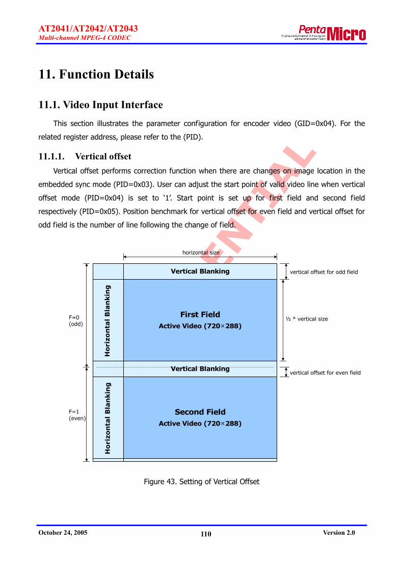
CONFI
DEN
TIAL
AT2041/AT2042/AT2043 Multi-channel MPEG-4 CODEC
October 24, 2005 Version 2.0 110
11. Function Details
11.1. Video Input Interface
This section illustrates the parameter configuration for encoder video (GID=0x04). For the
related register address, please refer to the (PID).
11.1.1. Vertical offset Vertical offset performs correction function when there are changes on image location in the
embedded sync mode (PID=0x03). User can adjust the start point of valid video line when vertical
offset mode (PID=0x04) is set to ‘1’. Start point is set up for first field and second field
respectively (PID=0x05). Position benchmark for vertical offset for even field and vertical offset for
odd field is the number of line following the change of field.
Second FieldActive Video (720×288)
Vertical Blanking
First FieldActive Video (720×288)
Ho
rizo
nta
l B
lan
kin
gH
ori
zon
tal
Bla
nkin
g
½ * vertical size
F=1(even)
F=0(odd)
Vertical Blanking
horizontal size
vertical offset for odd field
vertical offset for even field
Figure 43. Setting of Vertical Offset

CONFI
DEN
TIAL
AT2041/AT2042/AT2043 Multi-channel MPEG-4 CODEC
October 24, 2005 Version 2.0 111
11.1.2. Field decision In external sync mode, the field (PID=0x06) is decided as follows:
1) Using FSYNCIN
2) Using VSYNCIN and HSYNCIN
In the case of using VSYNCIN and HSYNCIN, if the time difference between VSYNCIN and
HSYNCIN is within first field decision parameter (PID=0x07), it is recognized for first field. If not,
it is recognized for second field.
VSYNCIN
HSYNCIN
First field decision parameter
Figure 44. First Field Decision Parameter
11.1.3. Polarity of Sync Signals By adjusting video input sync polarity (PID=0x08), a polarity of the external sync and valid
signal is decided. Figure 45 shows a polarity when register is set to ‘0’.
VSYNCIN
HSYNCIN
FSYNCIN first field second field
Active Low
Active Low
First field value
VVALIDIN
HVALIDIN
Active Low
Active Low0
0
0
0
0
Register Setting
VSYNCIN
HSYNCIN
FSYNCIN first field second field
Active Low
Active Low
First field value
VVALIDIN
HVALIDIN
Active Low
Active Low0
0
0
0
0
Register Setting
Figure 45. Polarity of Sync Signals
11.2. Video Output Interface
This section illustrates the parameter configuration for encoder video (GID=0x08). For the
related register address, please refer to the (PID).

CONFI
DEN
TIAL
AT2041/AT2042/AT2043 Multi-channel MPEG-4 CODEC
October 24, 2005 Version 2.0 112
11.2.1. Slave mode In the master mode (PID=0x03), AT2041 and AT2042 generate sync signals and send them
out. FSYNCOUT, VSYNCOUT and HSYNCOUT are used for output.
In the slave mode (0x03), video data are outputted according to the external field, vertical
and horizontal sync signals. In other words, FSYNCOUT, VSYNCOUT and HSYNCOUT are used for
input.
VVALIDOUT and HVALIDOUT, which indicate valid video data, are used for output regardless
of master mode or slave mode. HVALIDOUT is adjusted by configuring hsync_to_hvalid_end
(PID=0x07). And hsync_to_hvalid_end (PID=0x07) is operated only in slave mode (PID=0x03).
HSYNCOUT
HVALIDOUT
hsync_to_hvalid_endHSYNCOUT
HVALIDOUT
hsync_to_hvalid_end
Figure 46. H_VALID Timing
11.2.2. Vertical offset Vertical offset set the start point of valid video data. Vertical offset (PID=0x04) needs to be
set for first field and second field respectively. Figure 47 and Figure 48 show vertical offset for
NTSC as well as PAL.
For example in Figure 47, vertical offset for even field is set to 284, and vertical offset for odd
field is set to 21.

CONFI
DEN
TIAL
AT2041/AT2042/AT2043 Multi-channel MPEG-4 CODEC
October 24, 2005 Version 2.0 113
V ertica l B lank ing
Second F ie ldA ctive V ideo (720× 240)
V ertica l B lank ing
F irst F ie ldA ctive V ideo (720× 240)
Ho
rizo
nta
l B
lan
kin
gH
ori
zon
tal
Bla
nkin
g
1
1 9
2 2
26 1
26 4
28 2
28 5
52 452 5
34
26 526 6
52 5
F= 1
F= 0
F= 1
Figure 47. Vertical Offset for NTSC
S e c o n d F ie ldA c t iv e V id e o ( 7 2 0 × 2 8 8 )
V e r t ic a l B la n k in g
F ir s t F ie ldA c t iv e V id e o ( 7 2 0 × 2 8 8 )
Ho
rizo
nta
l B
lan
kin
gH
ori
zon
tal
Bla
nkin
g
1
2 22 3
3 1 0
3 3 6
6 2 3
34
3 1 23 1 3
F = 1
F = 0
V e r t ic a l B la n k in g3 1 1
3 3 5
6 2 5
Figure 48. Vertical Offset for PAL

CONFI
DEN
TIAL
AT2041/AT2042/AT2043 Multi-channel MPEG-4 CODEC
October 24, 2005 Version 2.0 114
11.2.3. Field decision In slave mode, field decision is made as follows:
1) Using FSYNCOUT
2) Using VSYNCOUT and HSYNCOUT
In the case of using FSYNCOUT, field is decided by field sync mode (PID=0x05). In the case
of using VSYNCOUT and HSYNCOUT, field decision is made by referring to field decision parameter
(PID=0x06). If the time difference between VSYNCOUT and HSYNCOUT is within first field
decision parameter (PID=0x06), it is recognized for first field. If not, it is recognized for second
field. FSYNCOUT, which is made by VSYNCOUT and HSYNCOUT, is varied at the first line after
VSYNCOUT is asserted.
VSYNCOUT
HSYNCOUT
First field decision parameter
VSYNCOUT
HSYNCOUT
First field decision parameter
Figure 49. First Field Decision Parameter
11.2.4. External Sync. signals In master sync mode, the chip provides configurations for FSYNCOUT, VSYNCOUT, HSYNCOUT,
VVALIDOUT and HVALIDOUT. In the horizontal sync control (PID=0x07), it assigns the start and
end point of HSYNCOUT.
FF 00 00 XY 80 10 80 10 CB Y CR Y80 10 80 10 FF 00 00 XY‥‥‥
EAV SAVHORIZONTAL BLANKING 4:2:2 DATA1 2 3 4 5 6 7 8 268 270 271 272 273 274 275 276 277 278 279 280 281
80 10 80 10 80 10 80 10
HSYNCOUT
horizotnal sync start position horizotnal sync end position0 1 . . .
FF 00 00 XY 80 10 80 10 CB Y CR Y80 10 80 10 FF 00 00 XY‥‥‥
EAV SAVHORIZONTAL BLANKING 4:2:2 DATA1 2 3 4 5 6 7 8 268 270 271 272 273 274 275 276 277 278 279 280 281
80 10 80 10 80 10 80 10
HSYNCOUT
horizotnal sync start position horizotnal sync end position0 1 . . .
Figure 50. Setting of HSYNCOUT
Vertical sync control (PID=0x08) configures VSYNCOUT every fields.

CONFI
DEN
TIAL
AT2041/AT2042/AT2043 Multi-channel MPEG-4 CODEC
October 24, 2005 Version 2.0 115
Vertical Blanking
Second FieldActive Video (720×240)
Vertical Blanking
First FieldActive Video (720×240)
Ho
rizo
nta
l B
lan
kin
gH
ori
zon
tal B
lan
kin
g
1
19
22
261
264
282
285
524525
Vertical sync start line number of the first field
Vertical sync end line number of the first field
Vertical sync start line number of the second field
Vertical sync end line number of the second field
Figure 51. VSYNCOUT Control – Line Position
VSYNCOUT
HVALIDOUT
Vertical sync transition position
VSYNCOUT
HVALIDOUT
Vertical sync transition position
Figure 52. VSYNCOUT Control – Pixel Position
Field sync control(PID=0x09) configures FSYNCOUT. It needs to set the line of field change,
and horizontal position.
11.2.5. Polarity of Sync. Signals By adjusting video output sync polarity (PID=0x0A), a polarity of FSYNCOUT, VSYNCOUT,
HSYNCOUT, VVALIDOUT and HVALIDOUT, which are being used for video output, can be decided.
Figure 53 shows a polarity when register is set to ‘0’.

CONFI
DEN
TIAL
AT2041/AT2042/AT2043 Multi-channel MPEG-4 CODEC
October 24, 2005 Version 2.0 116
VSYNCOUT
HSYNCOUT
FSYNCOUT first field second field
Active Low
Active Low
First field value
VVALIDOUT
HVALIDOUT
Active Low
Active Low0
0
0
0
0
Register Setting
VSYNCOUT
HSYNCOUT
FSYNCOUT first field second field
Active Low
Active Low
First field value
VVALIDOUT
HVALIDOUT
Active Low
Active Low0
0
0
0
0
Register Setting
Figure 53. Polarity of Video Output Sync
11.3. VBI (Vertical Blanking Interval)
11.3.1. VBI Extraction The AT204x is able to extract VBI (Vertical Blanking Interval) from the video input data, and
makes use of it for encoding. The AT204x handles VBI data (VBI_data_0 ~ 3) in vertical blanking
domain, except horizontal blanking domain. The AT204x extracts the consecutive four lines of data
from VBI_start_line. 48 bits per line can be extracted according to VBI_sampling_rate (1~64
pixels/VBI data) assigned by VBI_start_pixel.
The value of each data is asserted to ‘1’ if it is equal to or bigger than VBI_high_value, and
asserted to ‘0’ if it is smaller than VBI_high_value.

CONFI
DEN
TIAL
AT2041/AT2042/AT2043 Multi-channel MPEG-4 CODEC
October 24, 2005 Version 2.0 117
Second FieldActive Video (720×240)
First FieldActive Video (720×240)
Ho
rizo
nta
lB
lan
kin
g
Vertical Blanking
: VBI region
4 lines
Vertical Blanking
Hori
zon
tal
Bla
nkin
g
4 lines
VBI_start_lineVBI_data_0VBI_data_1VBI_data_2VBI_data_3
VBI_data_0VBI_data_1VBI_data_2VBI_data_3
VBI_start_lineVBI_data_0VBI_data_1VBI_data_2VBI_data_3
VBI_data_0VBI_data_1VBI_data_2VBI_data_3
Figure 54. VBI Extraction – Line Position
VBI_start_pixel
vertical blanking intervalhorizontalblanking
EAV SAV data region
VBI_sampling_rate
samplingposition
samplingposition
samplingposition
samplingposition
samplingposition
Figure 55. VBI Extraction – Pixel Position
11.3.2. VBI of Decoder Video The AT2041 and AT2042 are able to output the video data, which includes the decoded
images along with VBI data.

CONFI
DEN
TIAL
AT2041/AT2042/AT2043 Multi-channel MPEG-4 CODEC
October 24, 2005 Version 2.0 118
The AT2041 and AT2042 handle VBI data in vertical blanking domain, except horizontal
blanking domain. The AT2041 and AT2042 are able to insert a maximum of four consecutive lines
of data into VBI_start_line. And the data can be inserted by repeating insertion of VBI data as big
as VBI_sampling_rate assigned by VBI_start_pixel. 48 bits can be inserted per line. Each data is
1bit(0 or 1), consisting of VBI_value_zero and VBI_value_one.
vertical blanking intervalhorizontalblanking
EAV SAV VBIdata
VBIdata
VBIdata
VBIdata
VBIdataEAV SAV VBI
dataVBIdata
VBIdata
VBIdata
VBIdata
VBI_start_pixel VBI_sampling_rateVBI_start_pixel VBI_sampling_rate
Figure 56. VBI Insertion – Pixel Position
11.4. Channel ID Interface
11.4.1. Channel ID Interface Mode The AT204x can be interfaced to all types of video multiplex chip, which generates the
channel ID format as described on section 11.3. The AT204x receives the information on channel
ID, dummy flag and channel loss information from VBI. When the AT204x proceeds the frame
encoding, it decodes VBI information on the frame unit. And it decodes VBI information on the
field unit at field mode encoding.
The channel ID interface mode [GID = 0x4, PID = 0xC] of the AT204x needs to be set suit for
video multiplex chip. Refer to section 10.6.3 for channel ID interface mode that the AT204x
supports currently. If needed, it is possible to add channel ID interface mode for interface with
various channel multiplex chip.
0 = Single channel encoding mode
The AT204x doesn’t read channel ID from VBI, but encodes 0 channel only.
AT4012 interface mode
VBI_start_line = 7 (7th line from FSYNC transition line)
VBI_sampling_rate = 31 (32 VCLK_ENC clock cycles)

CONFI
DEN
TIAL
AT2041/AT2042/AT2043 Multi-channel MPEG-4 CODEC
October 24, 2005 Version 2.0 119
VBI_blanking_pixel = 15 (16 VCLK_ENC clock cycles)
VBI_high_value = 128
Channel ID = VBI_data_0[0:2]
Dummy flag = (VBI_data_0[0:3] == 0xC) ? 1 : 0;
AT4013 interface mode
VBI_start_line = 7 (7th line from FSYNC transition line)
VBI_sampling_rate = 31 (32 VCLK_ENC clock cycles)
VBI_blanking_pixel = 15 (16 VCLK_ENC clock cycles)
VBI_high_value = 128
Channel ID = VBI_data_0[0:3]
Dummy flag = (VBI_data_0[0:3] == 0xC) ? 1 : 0;
For detailed information about channel ID interface mode, refer to the AT204x application
note, ‘AT204x_AN05_ChannelID_Vxx(Eng).pdf’.
11.4.2. VBI Encoding Mode As illustrated on section 11.3, the AT2041 and AT2042 are capable of inserting a variety of
information into the VBI. Depending on VBI encoding mode [GID = 0x8, PID = 0x14], the AT2041
and AT2042 define the types of data and contents for output data into VBI differently. The
followings are the VBI encoding mode of the AT2041 and AT2042. We will keep updating various
modes if necessary.
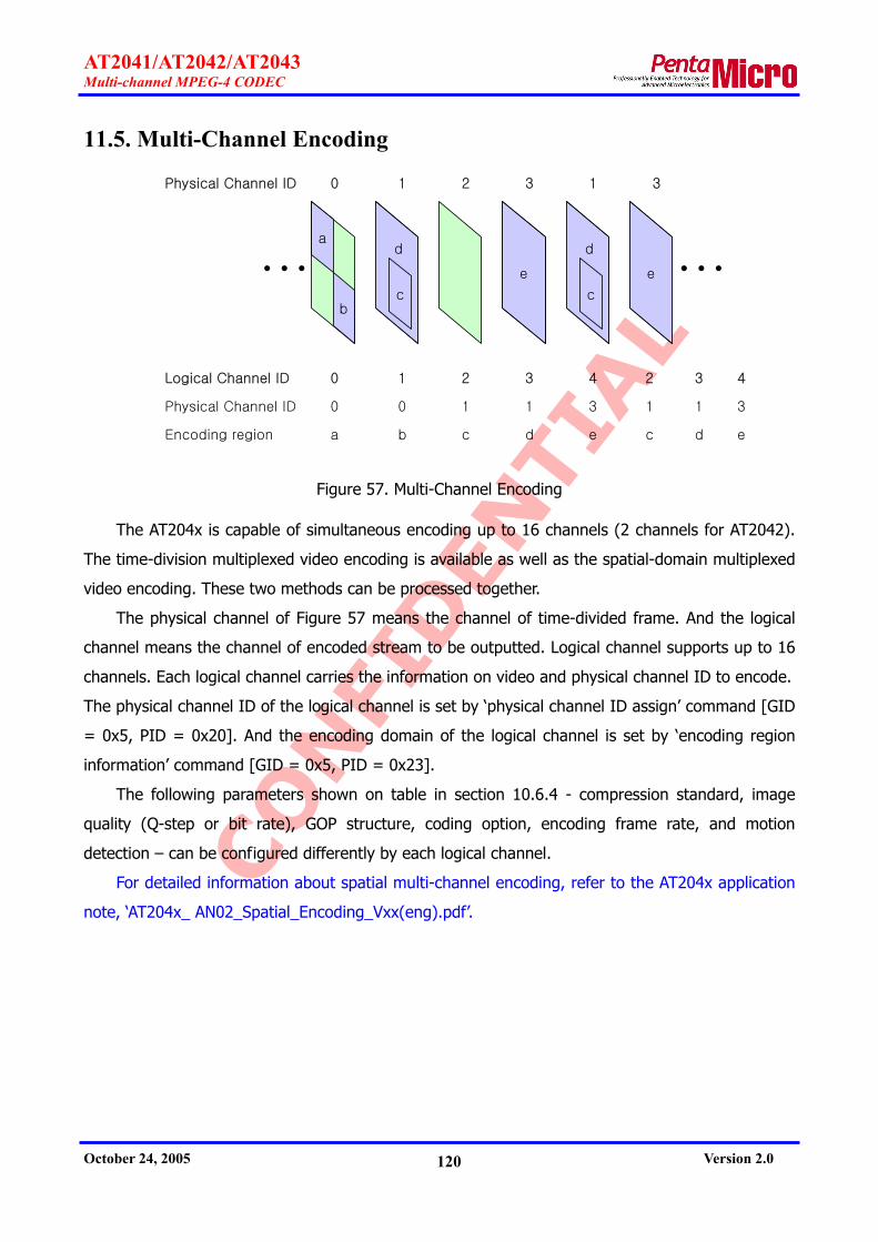
CONFI
DEN
TIAL
AT2041/AT2042/AT2043 Multi-channel MPEG-4 CODEC
October 24, 2005 Version 2.0 120
11.5. Multi-Channel Encoding
da
b
e
Physical Channel ID
… …0 1 2 3
c
Logical Channel ID 0 1 2 3 4
Physical Channel ID 0 0 1 1 3
Encoding region a b c d e
d
1
c
e
3
2 3
1 1
c d
4
3
e
Figure 57. Multi-Channel Encoding
The AT204x is capable of simultaneous encoding up to 16 channels (2 channels for AT2042).
The time-division multiplexed video encoding is available as well as the spatial-domain multiplexed
video encoding. These two methods can be processed together.
The physical channel of Figure 57 means the channel of time-divided frame. And the logical
channel means the channel of encoded stream to be outputted. Logical channel supports up to 16
channels. Each logical channel carries the information on video and physical channel ID to encode.
The physical channel ID of the logical channel is set by ‘physical channel ID assign’ command [GID
= 0x5, PID = 0x20]. And the encoding domain of the logical channel is set by ‘encoding region
information’ command [GID = 0x5, PID = 0x23].
The following parameters shown on table in section 10.6.4 - compression standard, image
quality (Q-step or bit rate), GOP structure, coding option, encoding frame rate, and motion
detection – can be configured differently by each logical channel.
For detailed information about spatial multi-channel encoding, refer to the AT204x application
note, ‘AT204x_ AN02_Spatial_Encoding_Vxx(eng).pdf’.

CONFI
DEN
TIAL
AT2041/AT2042/AT2043 Multi-channel MPEG-4 CODEC
October 24, 2005 Version 2.0 121
11.6. Multi-Channel Display
CH1
CH5
CH3
CH1
Display=1(on)Hor. scale mode=0(1:1)Ver. scale mode=0(1:1)Hor. offset=0Ver. offset=0Display level=bottom
CH3
Display=1(on)Hor. scale mode=1(2:1)Ver. scale mode=1(2:1)Hor. offset=1Ver. offset=3Display level=top
CH5
Display=1(on)Hor. scale mode=1(2:1)Ver. scale mode=1(2:1)Hor. offset=4Ver. offset=0Display level=middle
CH0
Display=0(off)
CH6
Display=0(off)
Figure 58. Multi-Channel Display
The AT2041 is capable of simultaneous decoding and live display up to 16 channels. A
maximum of 16 video output windows are available, and each decoding channel can be displayed
via different video output window.
As shown on Figure 58, after encoding five channels, three channels can be displayed at the
same time while other two channels are not being displayed on the screen. In this case, display
parameter [GID = 0x9, PID = 0x4] for CH1, CH3 and CH4 is set to ‘1’, and the parameter [GID =
0x9, PID = 0x4] for CH0 and CH6 is set to ‘0’. CH1 was not scaled down, but CH3 and CH5 was
scaled down by 2:1 [GID = 0x9, PID = 0x10]. Scale-down channel is positioned on the screen by
display offset parameter [GID = 0x9, PID = 0x11].
Each channel has different priority that locates the image at the upper or bottom position by
its priority. This priority setting is configured by display priority parameter [GID = 0x9, PID = 0x5].
In the above multi-channel, CH3’s priority is first, CH5 is second, and CH1 is last one.
The AT2041 and AT2042 have background image plane. The AT2041 supports sixteen video
output windows, and the AT2042 supports two video output windows. And the area where
decoded images are not outputted is covered with the background image. Arbitrary images or

CONFI
DEN
TIAL
AT2041/AT2042/AT2043 Multi-channel MPEG-4 CODEC
October 24, 2005 Version 2.0 122
input images can be displayed on the background image plane.
Video display output format is always frame one, and the AT204x does not support field
format. Even if decoded stream is progressive encoded stream, video output is displayed over two
fields.
11.7. Motion Detection
The AT204x provides motion detection function. User can set up motion detection sensitivity
[GID = 0x5, PID = 0x26] and motion detection area [GID = 0x5, PID = 0x27] individually by
channel. In the case of motion-less state, encoding can be stopped temporarily according to
recording mode [GID = 0x5, PID = 0x26].
The AT204x has the following five motion detection parameters:
Sensitivity: Motion detection sensitivity, using motion estimation algorithm, can be
controlled. The sensitivity control ranges from 0 to 7. The lower value it is, the more
sensitivity it has.
Pixel difference threshold and Different pixel count threshold: It checks the pixel difference
of frame to frame within one macro block. If the number of pixel, exceeding ‘pixel
difference threshold’, is bigger than ‘different pixel count threshold’, the macro block is
regarded as motion block. If the above two parameters become smaller, motion detection
reacts more sensitively. These parameters are used along with the motion detection
utilizing motion estimation algorithm.
Motion MB count threshold: If the number of motion macro block, detected as motion by
the ‘motion detection by motion estimation algorithm’ and ‘the motion detection by pixel
difference’, is bigger than ‘motion MB count threshold’, the macro block is regarded as
motion block. The lower value it is, the more sensitivity it has.
Motion-less frame count threshold: If a frame without any motion appears continuously
over ‘motion-less frame count threshold’ when motion-less frame recording mode [GID =
0x5, PDI = 0x25] is '1’, the chip is not encoding any longer until moving objects reappear.
The higher value it is, the more sensitivity it has. As the AT204x detects motion only for I-
picture or P-picture, it determines B-frame, which locates between motion-less I-picture or
P-picture, as motion-less frame.
As illustrated on Figure 59, motion detection area is configured using 54(=3*18) of 8-bit data
[GID = 0x5, PID = 0x27]. Each bit is allocated to 2x2 macroblock, and three 8-bit data are
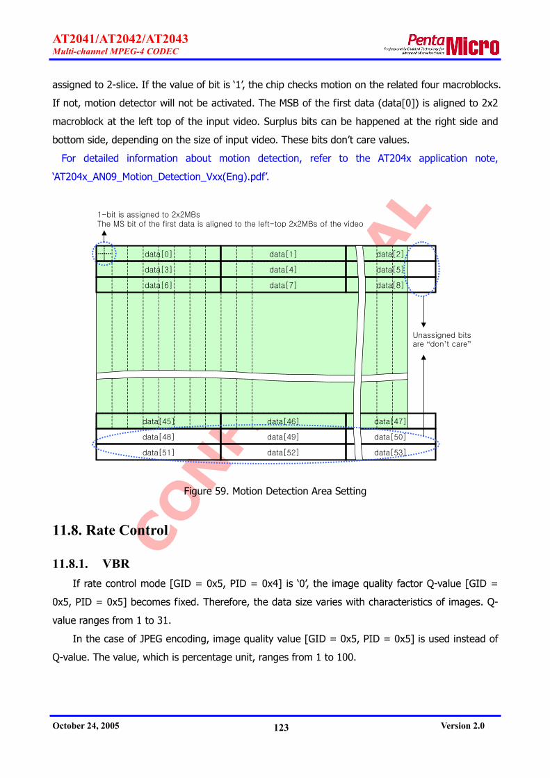
CONFI
DEN
TIAL
AT2041/AT2042/AT2043 Multi-channel MPEG-4 CODEC
October 24, 2005 Version 2.0 123
assigned to 2-slice. If the value of bit is ‘1’, the chip checks motion on the related four macroblocks.
If not, motion detector will not be activated. The MSB of the first data (data[0]) is aligned to 2x2
macroblock at the left top of the input video. Surplus bits can be happened at the right side and
bottom side, depending on the size of input video. These bits don’t care values.
For detailed information about motion detection, refer to the AT204x application note,
‘AT204x_AN09_Motion_Detection_Vxx(Eng).pdf’.
data[0] data[1] data[2]
data[3] data[4] data[5]
data[45] data[46] data[47]
data[48] data[49] data[50]
data[51] data[52] data[53]
data[6] data[7] data[8]
1-bit is assigned to 2x2MBsThe MS bit of the first data is aligned to the left-top 2x2MBs of the video
Unassigned bits are “don’t care”
Figure 59. Motion Detection Area Setting
11.8. Rate Control
11.8.1. VBR If rate control mode [GID = 0x5, PID = 0x4] is ‘0’, the image quality factor Q-value [GID =
0x5, PID = 0x5] becomes fixed. Therefore, the data size varies with characteristics of images. Q-
value ranges from 1 to 31.
In the case of JPEG encoding, image quality value [GID = 0x5, PID = 0x5] is used instead of
Q-value. The value, which is percentage unit, ranges from 1 to 100.

CONFI
DEN
TIAL
AT2041/AT2042/AT2043 Multi-channel MPEG-4 CODEC
October 24, 2005 Version 2.0 124
11.8.2. CBR If rate control mode [GID = 0x5, PID = 0x4] is ‘1’ or ‘2’, the AT204x automatically controls Q-
value to maintain the uniform data size per frame as given bit rate [GID = 0x5, PID = 0x6]. Bit
rate [GID = 0x5, PID = 0x6] shows the average data size per frame.
CBR function is also useful when it is used with multi-channel encoding and motion detection
because bit rate can be differently configured by channel in a multi-channel encoding.
In case that the given value of CBR is set unrealistically (extremely big or small), not
considering characteristics of images, bigger or smaller data than the given bit rate could be
generated. However, the AT204x doesn’t do unnecessary byte stuffing to meet the given value
even if the smaller data than the given value is generated.
11.9. Frame Rate Control
CH0: input frame = 1, recoding frame = 1CH1: input frame = 2, recoding frame = 1CH2: input frame = 3, recoding frame = 1CH3: input frame = 4, recoding frame = 2
Channel ID: 0 1 2 3 0 1 2 3 0 1 2 3 0 1 2 3 0 1 2 3 0 1 2 3 0 1 2 3 0 1 2 3 0 1 2 3 0 1 2 3
Figure 60. Frame Rate Control
There are two methods to control encoding frame rate of the AT204x. One is to control the
frame rate by informing the AT204x of the information on encoding frame and dummy frame
through VBI. Another is to take a random sample of incoming frame in accordance with encoding
frame rate control [GID = 0x5, PID = 0x24].
In the above Figure 60, CH0 encodes every frame coming in, CH1 encodes one frame of two,
CH2 encodes one frame of three, and CH3 encodes two frames of four. In the case of CH3
encoding, it encodes two frames came first and then deserts two frames came later. In this case, it
will be ideal configuration to encode one frame of two.
11.10. GOP Structure
The AT204x makes use of GOP_NM(=N/M) and GOP_M(=M) to organize GOP structure [GID
= 0x5, PID = 0x7] instead of N(distance between I-picture to I-picture), M(distance between I-
picture to P-picture or distance between P-picture to P-picture). Thus, N equals to GOP_NM *
GOP_M, and M is GOP_M. GOP_NM ranges from 1 to 255, and GOP_M ranges from 1 to 3
Although GOP_M is bigger than ‘1’, the first GOP starts with I, I,… or I, P,… when encoding

CONFI
DEN
TIAL
AT2041/AT2042/AT2043 Multi-channel MPEG-4 CODEC
October 24, 2005 Version 2.0 125
began. In case that motion-less frame recording mode [GID = 0x5, PID = 0x25] is ‘1’ and there
are no moving objects, encoding will stop at I-picture or P-picture and resume with new GOP
structure when motion reappears. Likewise, the first GOP starts with I, I,… or I, P,… when the chip
resumes encoding.
For example of GOP_NM = 3, GOP_M = 3, the GOP are as follows:
IPBBPBB IBBPBBPBB IBB…[Motion-less frame skip]… IPBBPBB IBBPBBPBB…
11.11. Encoder Output Data Size Control
The AT204x generates data ready message [GID = 0x1, MID = 0x1] so that the host reads
encoding data as big as output data size (256-bit unit) via multiplex FIFO (See section 8.2.5).
The host restricts the data size generated per data ready message by configuring maximum
output data size [GID = 0x1, PID = 0x5]. If the size of encoding data exceeds maximum output
data size (Kbytes unit), the AT204x divides the encoding data into several smaller data than
maximum output data size, and generates data ready message as many as the number of divided
data. And when the last data of a frame is being sent out, the last flag of data ready message is
set to ‘1’ to distinguish frame to frame. Otherwise, the last flag is ‘0’. If the last flag is ‘0’, the host
should transfer only ‘ack for Tx’ parameter [GIO = 0x0, PID = 0x1] to the AT204x but should not
transfer ‘ack for data ready message’ parameter [GID = 0x1, PID = 0x1]. If the last flag is ‘1’ the
host should transfer both parameters to the AT204x. Refer to Figure 41. Encoding Sequence.
The AT204x can generate next Tx message only after it receives ‘ack for Tx’ parameter, so if
the host does not transfer ‘ack for Tx’ parameter after receiving Tx message, the AT204x cannot
generate next Tx message. As the same way, the AT204x can generate next ‘data ready message’
only after it receives ‘ack for data ready message’ parameter.
11.12. Decoder Input Data Size Control
The AT2041 and AT2042 generate data request message [GID = 0x2, MID = 0x1] so that the
host writes decoding data into de-multiplex FIFO(See section 8.2.6).
When the host receives data request message, it can write data into the AT2041/AT2042 as
follows:
One is to transfer all data of a decoding frame into the AT2041/AT2042 at once, and sends
out acknowledge for data request’ parameter [GID = 0x2, PID = 0x1] to the AT2041/AT2042.
Another is to transfer data of a decoding frame into the AT2041/AT2042 several times. In this
CONFI
DEN
TIAL
AT2041/AT2042/AT2043 Multi-channel MPEG-4 CODEC
October 24, 2005 Version 2.0 126
case, the host sends ‘alternative acknowledge for data request’ parameter [GID = 0x2, PID =
0x30] to the AT2041/AT2042 each time after transmitting decoding data. And after the last data of
a frame is sent out, the ack_mode field of ‘alternative acknowledge for data request’ parameter is
set to ‘1’ to distinguish frame to frame. Otherwise, the ack_mode field is ‘0’.
If the host cannot transfer data to the AT2041/AT2042 immediately after ‘data request
message’, the host can transfer only ‘alternative acknowledge for data request’ parameter as
ack_mode field is set to ‘2’. In this case, the AT2041/AT204x generates again ‘data request
message’ after 10 msec.
After all data of a frame is transferred, the zero stuffing data more than 256 bit should be
sent to the AT2041/AT204x. If transfer data of a frame is divided several times, 256 bit stuffing
should be sent only after the last data of a frame is transferred.

CONFI
DEN
TIAL
AT2041/AT2042/AT2043 Multi-channel MPEG-4 CODEC
October 24, 2005 Version 2.0 127
12. Electrical Specifications
12.1. Electrical specification
12.1.1. Maximum Ratings
Table 18. Maximum Ratings Vss=0V
Parameter Symbol Ratings Unit
Power Supply Voltage VDD -0.5 to 2.5 *1
-0.5 to 4.0 *2 V
Input Voltage VI -0.5 to VDD +0.5 (≤ 2.5V) *1
-0.5 to VDD +0.5 (≤ 4.0V) *2 V
Output Voltage VO -0.5 to VDD +0.5 (≤ 2.5V) *1
-0.5 to VDD +0.5 (≤ 4.0V) *2 V
Storage Temperature TST -55 to 125 OC Junction Temperature Tj -40 to 125 OC
Output Current *3 IO ±10 (3.3V CMOS, 2.5V CMOS) ± 7.5 (1.8V CMOS) mA
Input Signal Transfer Rate RI Clock input *4: 200 Normal input: 100 Mbps *5
Output Signal Transfer Rate RO 100 Mbps *5
Output Load Capacitance CO 3000/RO pF
Power Supply Pin Current *6 ID VDDE = 59 *6 VDDI = 34 mA
Input Signal Invalid Duration TZ 10 ms
*1 Internal gate area when single-power supply and dual-power supply are used.
*2 I/O area when 3.3V I/F or 2.5V I/F is used at dual-power supply.
*3 DC current that continuously flows for 10ms or more, or average DC current.
*4 It is required to use I/O cells for clock input.
*5 bps = bit/sec.
*6 VDD, Power supply pin current value per GND pin [mA]

CONFI
DEN
TIAL
AT2041/AT2042/AT2043 Multi-channel MPEG-4 CODEC
October 24, 2005 Version 2.0 128
12.1.2. Recommended Operating Condition
Table 19. Recommended Operating Condition
Dual-power Supply (VDDE = 3.3V ± 0.3V/VDDI = 1.8V ± 0.15V, VSS = 0V)
Ratings Parameter SymbolMin. Typ. Max.
Unit
VDDE 3.0 3.3 3.6 V Power Supply Voltage VDDI 1.65 1.8 1.95
H-level Input Voltage 3.3V CMOS VIH 2.0 -- VDDE+0.3 V L-level Input Voltage 3.3V CMOS VIL -0.3 -- 0.8 V
Ambient Temperature Ta 0 -- 70 OC
12.1.3. DC Characteristics
Table 20. DC Characteristics
Dual-power Supply (VDDE=3.3V/VDDI=1.8V, 1.5V, 1.1V)
Measurement Condition (VDDE=3.3 ± 0.3V/VDDI=1.8 ± 0.15V, 1.5 ± 0.1V, 1.1 ± 0.1V, VSS
= 0V, Tj = -40 to 125 °C)
Specification Parameter Symbol Condition Min. Typ. Max.
Unit
VOH4 3.3V output IOH=-100uA VDDE-0.2 -- VDDE V H-level Output Voltage VOH2 1.8V output IOH=-100uA VDDI-0.2 -- VDDI V VOL4 3.3V output IOL=100uA 0 -- 0.2 V L-level Output Voltage VOL2 1.8V output IOL=100uA 0 -- 0.2 V
3.3V VDDE=3.3V±0.3V *1 -- H-level Output V-I Characteristics --
1.8V VDDI=1.8V±0.15V *2 -- 3.3V VDDE=3.3V±0.3V *1 -- L-level Output V-I
Characteristics -- 1.8V VDDI=1.8V±0.15V *2 --
Input Leakage Current IL -- -- ±5 uA 3.3V pull-up VIL=0 pull-down VIH=VDDE
10 33 80 Pull-up/Pull-down Register Rp
1.8V pull-up VIL=0 pull-down VIH=VDDI
8 18 40 kΩ
*1 See Figure 61 and Figure 62.

CONFI
DEN
TIAL
AT2041/AT2042/AT2043 Multi-channel MPEG-4 CODEC
October 24, 2005 Version 2.0 129
Figure 61. 3.3V I/O L, M Type V-I Characteristics
Figure 62. 3.3V I/O H, V Type V-I Characteristics

CONFI
DEN
TIAL
AT2041/AT2042/AT2043 Multi-channel MPEG-4 CODEC
October 24, 2005 Version 2.0 130
Table 21. Output Pin Type
Pin Name
L, M Type JTAG, GIO, Audio I/F, Video I/F
H, V Type Host I/F, SDRAM I/F
12.1.4. Power Consumption
Table 22. Power Consumption
Parameter Symbol Rating Unit
Internal Power (1.8V) P1.8 594 mW
IO Power (3.3V) P3.3 106 mW
Internal Current (1.8V) I1.8 330 mA
IO Current (3.3V) I3.3 32 mA
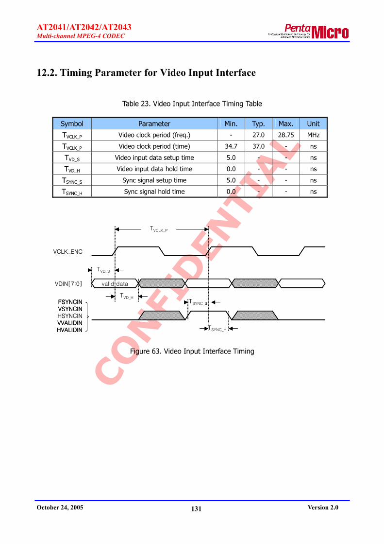
CONFI
DEN
TIAL
AT2041/AT2042/AT2043 Multi-channel MPEG-4 CODEC
October 24, 2005 Version 2.0 131
12.2. Timing Parameter for Video Input Interface
Table 23. Video Input Interface Timing Table
Symbol Parameter Min. Typ. Max. Unit
TVCLK_P Video clock period (freq.) - 27.0 28.75 MHz
TVCLK_P Video clock period (time) 34.7 37.0 - ns
TVD_S Video input data setup time 5.0 - - ns
TVD_H Video input data hold time 0.0 - - ns
TSYNC_S Sync signal setup time 5.0 - - ns
TSYNC_H Sync signal hold time 0.0 - - ns
valid data
TVCLK_P
TVD_S
TVD_HTSYNC_S
TSYNC_H
VCLK_ENC
VDIN[7:0]
FSYNCINVSYNCINHSYNCINVVALIDINHVALIDIN
valid data
TVCLK_P
TVD_S
TVD_HTSYNC_S
TSYNC_H
VCLK_ENC
VDIN[7:0]
FSYNCINVSYNCINHSYNCINVVALIDINHVALIDIN
Figure 63. Video Input Interface Timing

CONFI
DEN
TIAL
AT2041/AT2042/AT2043 Multi-channel MPEG-4 CODEC
October 24, 2005 Version 2.0 132
12.3. Timing Parameter for Video Output Interface
Table 24. Video Output Interface Timing Table
Symbol Parameter Min. Typ. Max. Unit
TVCLK_P Video clock period (freq.) - 27.0 28.75 MHz
TVCLK_P Video clock period (time) 34.7 37.0 - ns
TVD_D Video output data delay time - - 16.0 ns
TVD_H Video output data hold time 5.0 - - ns
TSYNCO_D Sync output signal delay time - - 16.0 ns
TSYNCO_H Sync output signal hold time 5.0 - - ns
TSYNCI_S Sync input signal setup time 7.0 - - ns
TSYNCI_H Sync input signal hold time 0.0 - - ns
valid data
TVCLK_P
TVD_H
TSYNCO_H
VCLK_DEC
VDOUT[7:0]
FSYNCOUTVSYNCOUTHSYNCOUTVVALIDOUTHVALIDOUT
TSYNCI_S
TSYNCI_H
FSYNCOUTVSYNCOUTHSYNCOUT
Slave mode
TVD_D
TSYNCO_D
valid data
TVCLK_P
TVD_H
TSYNCO_H
VCLK_DEC
VDOUT[7:0]
FSYNCOUTVSYNCOUTHSYNCOUTVVALIDOUTHVALIDOUT
TSYNCI_S
TSYNCI_H
FSYNCOUTVSYNCOUTHSYNCOUT
Slave mode
TVD_D
TSYNCO_D
Figure 64. Video Output Interface Timing

CONFI
DEN
TIAL
AT2041/AT2042/AT2043 Multi-channel MPEG-4 CODEC
October 24, 2005 Version 2.0 133
12.4. Timing Parameter for Audio Interface
Table 25. Audio Input Interface Timing Table
Symbol Parameter Min. Typ. Max. Unit
Clock Timing (I2S mode, Left Justified mode)
TACLK_P Audio clock period (freq.) 1.024 - 12.288 MHz
TACLK_P Audio clock period (time) 81.3 - 976.5 ns
Clock Timing (PCM mode)
TACLK_P Audio clock period (freq.) 1.024 - 2.048 MHz
TACLK_P Audio clock period (time) 488.2 - 976.5 ns
Signal Timing
TAFSR_S Frame sync setup time 6.0 - - ns
TAFSR_H Frame sync hold time 0.0 - - ns
TADR_S Audio input data setup time 4.0 - - ns
TADR_H Audio input data hold time 0.0 - - ns
TACLK_P
TAFSR_S
TAFSR_HTADR_S
TADR_H
ACLK_ENC
AFSR
ADR high or low
TACLK_P
TAFSR_S
TAFSR_HTADR_S
TADR_H
ACLK_ENC
AFSR
ADR high or low
Figure 65. Audio Input Interface Timing

CONFI
DEN
TIAL
AT2041/AT2042/AT2043 Multi-channel MPEG-4 CODEC
October 24, 2005 Version 2.0 134
Table 26. Audio Output Interface Timing Table
Symbol Parameter Min. Typ. Max. Unit
Clock Timing (I2S mode, Left Justified mode)
TACLK_P Audio clock period (freq.) 1.024 - 12.288 MHz
TACLK_P Audio clock period (time) 81.3 - 976.5 ns
Clock Timing (I2S mode, Left Justified mode)
TACLK_P Audio clock period (freq.) 1.024 - 2.048 MHz
TACLK_P Audio clock period (time) 488.2 - 976.5 ns
Signal Timing
TAFSXO_D Frame sync output delay time - - 40.0 ns
TAFSXO_H Frame sync output hold time 15.0 - - ns
TAFSXI_S Frame sync input setup time 6.0 - - ns
TAFSXI_H Frame sync input hold time 0.0 - - ns
TADX_D Audio data output delay time - - 52.0 ns
TADX_H Audio data output hold time 20.0 - - ns
TADX_H
TACLK_P
TAFSXO_H
ACLK_DEC
AFSX(master)
ADX
TAFSXI_S
TAFSXI_H
AFSX(slave)
high or low
TADX_D
TAFSXO_D
TADX_H
TACLK_P
TAFSXO_H
ACLK_DEC
AFSX(master)
ADX
TAFSXI_S
TAFSXI_H
AFSX(slave)
high or low
TADX_D
TAFSXO_D
Figure 66. Audio Output Interface Timing

CONFI
DEN
TIAL
AT2041/AT2042/AT2043 Multi-channel MPEG-4 CODEC
October 24, 2005 Version 2.0 135
12.5. Timing Parameter for SDRAM Interface
Table 27. SDRAM Interface Timing Table
Symbol Parameter Min. Typ. Max. Unit
TDCLK_P SDRAM clock period (freq.) 108.0 - 115.0 MHz
TDCLK_P SDRAM clock period (time) 8.69 - 9.25 ns
TDDO_D Data output delay time - 7.3 ns
TDDO_H Data output hold time 2.3 - - ns
TDDI_S Data input setup time 0.0 - - ns
TDDI_H Data input hold time 1.9 - - ns
TDCO_D Control signal output delay time - - 7.3 ns
TDCO_H Control signal output hold time 2.8 - - ns
valid
output input
TDCLK_P
TDDO_H
DCLK
DD[31:0]
DA[12:0],DBA[1:0],
nDCS,nDRAS,nDCAS, nDWE
DQM[3:0]DCKE
TDDI_S
TDDI_H
TDCO_H
TDDO_D
TDCO_D
valid
output input
TDCLK_P
TDDO_H
DCLK
DD[31:0]
DA[12:0],DBA[1:0],
nDCS,nDRAS,nDCAS, nDWE
DQM[3:0]DCKE
TDDI_S
TDDI_H
TDCO_H
TDDO_D
TDCO_D
Figure 67. SDRAM Interface Timing

CONFI
DEN
TIAL
AT2041/AT2042/AT2043 Multi-channel MPEG-4 CODEC
October 24, 2005 Version 2.0 136
12.6. Timing Parameter for Host Interface
Table 28. Host Interface Timing Table
Symbol Parameter Min. Typ. Max. Unit
THCLK_P Host clock period (freq.) - - 70.0 MHz
THCLK_P Host clock period (time) 14.2 - - ns
THDO_D Host data output delay time - - 9.0 ns
THDO_H Host data output hold time 3.0 - - ns
THDI_S Host data input setup time 5.0 - - ns
THDI_H Host data input hold time 0.0 - - ns
THCO_D Control signal output delay time - - 9.0 ns
THCO_S Control signal output hold time 3.0 - - ns
THCI_S Control signal input setup time 5.0 - - ns
THCI_H Control signal hold time 0.0 - - ns
valid
valid
output input
THCLK_P
THDO_H
HCLK
HD[15:0]
HA[2:0],nCS,nBS,
nBIP,nBURST,nWR_RD,nOE/RD
nWAIT/READYnIRQ/INT
THDI_S
THDI_HTHCI_S
THCI_H
THCO_H
THDO_D
THCO_D
valid
valid
output input
THCLK_P
THDO_H
HCLK
HD[15:0]
HA[2:0],nCS,nBS,
nBIP,nBURST,nWR_RD,nOE/RD
nWAIT/READYnIRQ/INT
THDI_S
THDI_HTHCI_S
THCI_H
THCO_H
THDO_D
THCO_D
Figure 68. Host Interface Timing

CONFI
DEN
TIAL
AT2041/AT2042/AT2043 Multi-channel MPEG-4 CODEC
October 24, 2005 Version 2.0 137
12.7. Timing Parameter for SPI ROM Interface
Table 29. SPI ROM Interface Timing Table
Symbol Parameter Min. Typ. Max. Unit
TSPICLK_P SPI ROM clock period (freq.) 13.5 14.0 14.5 MHz
TSPICLK_P SPI ROM clock period (time) 69.1 - 74.1 ns
TSPIO_D Output signal delay time - - 1.4 ns
TSPIO_H Output signal hold time 0.0 - - ns
TSPII_S Input signal setup time 16.0 - - ns
TSPII_H Input signal hold time 0.0 - - ns
TSPICLK_P
TSPII_S
SPI_CK
SPI_CSNSPI_HDNSPI_DO
SPI_DI
TSPIO_D
TSPIO_H
TSPII_S
TSPICLK_P
TSPII_S
SPI_CK
SPI_CSNSPI_HDNSPI_DO
SPI_DI
TSPIO_D
TSPIO_H
TSPII_S
Figure 69. SPI ROM Interface Timing

CONFI
DEN
TIAL
AT2041/AT2042/AT2043 Multi-channel MPEG-4 CODEC
October 24, 2005 Version 2.0 138
13. Pin Assignments
AT2041
1 2 3 4 5 6 7 8 9 10 11 12 13 14 15 16 17 18 19 20 21 22 23 24 25 26 27 28 29 30 31 32 33 34 35 36 37 38 39 40 41 42 43 44 45 46 47 48 49 50 51 52
TEST1
TEST0
VS
SFS
YN
CIN
VSYN
CIN
HSYN
CIN
VVALI
DIN
HVALI
DIN
VD
IN0
VD
DE
VD
IN1
VD
IN2
VD
IN3
VD
IN4
VS
SVD
IN5
VD
IN6
VD
IN7
VD
DI
VCLK
_EN
CAFS
RAD
RM
C1
MC
0ACLK
_EN
CV
SS
VD
DI
HD
15
HD
14
VS
SA
SYSC
LKV
DD
AO
SC
_EB
VD
DI
HD
13
HD
12
HD
11
VS
SH
D10
HD
9H
D8
HD
7V
DD
EH
D6
HD
5H
D4
HD
3H
D2
HD
1V
SS
HD
0H
A2
156
155
154
153
152
151
150
149
148
147
146
145
144
143
142
141
140
139
138
137
136
135
134
133
132
131
130
129
128
127
126
125
124
123
122
121
120
119
118
117
116
115
114
113
112
111
110
109
108
107
106
105
DD
QM
2V
DD
IV
SS
DD
QM
3nD
WE
nD
RAS
VS
SnD
CS
nD
CAS
VD
DE
DBA0
DBA1
VS
SD
CLK
VD
DI
DA0
DA1
DA2
VS
SD
CLK
_FB
VD
DI
DA3
DA4
VD
DE
DA5
VD
DI
VS
SD
A6
DA7
DA8
DA9
VS
SD
A10
DA11
DA12
VD
DI
ACLK
_D
EC
VS
SAD
XAFS
XV
DD
IVCLK
_D
EC
VD
DE
VD
OU
T0
VD
OU
T1
VD
OU
T2
VD
OU
T3
VD
OU
T4
VD
OU
T5
VS
SVD
OU
T6
VD
OU
T7
5354555657585960616263646566676869707172737475767778798081828384858687888990919293949596979899100101102103104 HSYNCOUT
VSYNCOUTFSYNCOUTHVALIDOUTVVALIDOUTRTCKTDOVDDEnRESETVSSTCKTMSTDInTRSTJTAGMODEGIO0GIO1GIO2VDDIVSSGIO3GIO4GIO5GIO6GIO7VDDIGIO8GIO9GIO10GIO11GIO12VDDIVSSGIO13GIO14GIO15nBURSTnBIPnIRQ/INTnWAIT/READYnOE/RDnWR_RDHCLKVDDEVSSnBSnCSCPU_SEL0CPU_SEL1CPU_SEL2HA0HA1208
207206205204203202201200199198197196195194193192191190189188187186185184183182181180179178177176175174173172171170169168167166165164163162161160159158157DDQM1
VDDEDDQM0
DD31DD30DD29DD28VSS
VDDEDD27DD26VSS
VDDIDD25DD24DD23DD22DD21DD20VSS
VDDIDD19DD18VSS
DD17DD16VDDIDD15VDDEDD14DD13DD12VSS
VDDIDD11DD10DD9DD8
VDDIDD7DD6DD5DD4VSS
VDDEDD3DD2VSSDD1DD0
DCKEIDDQ
MultiStream ⅣAT2041
1 2 3 4 5 6 7 8 9 10 11 12 13 14 15 16 17 18 19 20 21 22 23 24 25 26 27 28 29 30 31 32 33 34 35 36 37 38 39 40 41 42 43 44 45 46 47 48 49 50 51 52
TEST1
TEST0
VS
SFS
YN
CIN
VSYN
CIN
HSYN
CIN
VVALI
DIN
HVALI
DIN
VD
IN0
VD
DE
VD
IN1
VD
IN2
VD
IN3
VD
IN4
VS
SVD
IN5
VD
IN6
VD
IN7
VD
DI
VCLK
_EN
CAFS
RAD
RM
C1
MC
0ACLK
_EN
CV
SS
VD
DI
HD
15
HD
14
VS
SA
SYSC
LKV
DD
AO
SC
_EB
VD
DI
HD
13
HD
12
HD
11
VS
SH
D10
HD
9H
D8
HD
7V
DD
EH
D6
HD
5H
D4
HD
3H
D2
HD
1V
SS
HD
0H
A2
1 2 3 4 5 6 7 8 9 10 11 12 13 14 15 16 17 18 19 20 21 22 23 24 25 26 27 28 29 30 31 32 33 34 35 36 37 38 39 40 41 42 43 44 45 46 47 48 49 50 51 521 2 3 4 5 6 7 8 9 10 11 12 13 14 15 16 17 18 19 20 21 22 23 24 25 26 27 28 29 30 31 32 33 34 35 36 37 38 39 40 41 42 43 44 45 46 47 48 49 50 51 52
TEST1
TEST0
VS
SFS
YN
CIN
VSYN
CIN
HSYN
CIN
VVALI
DIN
HVALI
DIN
VD
IN0
VD
DE
VD
IN1
VD
IN2
VD
IN3
VD
IN4
VS
SVD
IN5
VD
IN6
VD
IN7
VD
DI
VCLK
_EN
CAFS
RAD
RM
C1
MC
0ACLK
_EN
CV
SS
VD
DI
HD
15
HD
14
VS
SA
SYSC
LKV
DD
AO
SC
_EB
VD
DI
HD
13
HD
12
HD
11
VS
SH
D10
HD
9H
D8
HD
7V
DD
EH
D6
HD
5H
D4
HD
3H
D2
HD
1V
SS
HD
0H
A2
156
155
154
153
152
151
150
149
148
147
146
145
144
143
142
141
140
139
138
137
136
135
134
133
132
131
130
129
128
127
126
125
124
123
122
121
120
119
118
117
116
115
114
113
112
111
110
109
108
107
106
105
DD
QM
2V
DD
IV
SS
DD
QM
3nD
WE
nD
RAS
VS
SnD
CS
nD
CAS
VD
DE
DBA0
DBA1
VS
SD
CLK
VD
DI
DA0
DA1
DA2
VS
SD
CLK
_FB
VD
DI
DA3
DA4
VD
DE
DA5
VD
DI
VS
SD
A6
DA7
DA8
DA9
VS
SD
A10
DA11
DA12
VD
DI
ACLK
_D
EC
VS
SAD
XAFS
XV
DD
IVCLK
_D
EC
VD
DE
VD
OU
T0
VD
OU
T1
VD
OU
T2
VD
OU
T3
VD
OU
T4
VD
OU
T5
VS
SVD
OU
T6
VD
OU
T7
156
155
154
153
152
151
150
149
148
147
146
145
144
143
142
141
140
139
138
137
136
135
134
133
132
131
130
129
128
127
126
125
124
123
122
121
120
119
118
117
116
115
114
113
112
111
110
109
108
107
106
105
156
155
154
153
152
151
150
149
148
147
146
145
144
143
142
141
140
139
138
137
136
135
134
133
132
131
130
129
128
127
126
125
124
123
122
121
120
119
118
117
116
115
114
113
112
111
110
109
108
107
106
105
DD
QM
2V
DD
IV
SS
DD
QM
3nD
WE
nD
RAS
VS
SnD
CS
nD
CAS
VD
DE
DBA0
DBA1
VS
SD
CLK
VD
DI
DA0
DA1
DA2
VS
SD
CLK
_FB
VD
DI
DA3
DA4
VD
DE
DA5
VD
DI
VS
SD
A6
DA7
DA8
DA9
VS
SD
A10
DA11
DA12
VD
DI
ACLK
_D
EC
VS
SAD
XAFS
XV
DD
IVCLK
_D
EC
VD
DE
VD
OU
T0
VD
OU
T1
VD
OU
T2
VD
OU
T3
VD
OU
T4
VD
OU
T5
VS
SVD
OU
T6
VD
OU
T7
5354555657585960616263646566676869707172737475767778798081828384858687888990919293949596979899100101102103104 HSYNCOUT
VSYNCOUTFSYNCOUTHVALIDOUTVVALIDOUTRTCKTDOVDDEnRESETVSSTCKTMSTDInTRSTJTAGMODEGIO0GIO1GIO2VDDIVSSGIO3GIO4GIO5GIO6GIO7VDDIGIO8GIO9GIO10GIO11GIO12VDDIVSSGIO13GIO14GIO15nBURSTnBIPnIRQ/INTnWAIT/READYnOE/RDnWR_RDHCLKVDDEVSSnBSnCSCPU_SEL0CPU_SEL1CPU_SEL2HA0HA153
54555657585960616263646566676869707172737475767778798081828384858687888990919293949596979899100101102103104
5354555657585960616263646566676869707172737475767778798081828384858687888990919293949596979899100101102103104 HSYNCOUT
VSYNCOUTFSYNCOUTHVALIDOUTVVALIDOUTRTCKTDOVDDEnRESETVSSTCKTMSTDInTRSTJTAGMODEGIO0GIO1GIO2VDDIVSSGIO3GIO4GIO5GIO6GIO7VDDIGIO8GIO9GIO10GIO11GIO12VDDIVSSGIO13GIO14GIO15nBURSTnBIPnIRQ/INTnWAIT/READYnOE/RDnWR_RDHCLKVDDEVSSnBSnCSCPU_SEL0CPU_SEL1CPU_SEL2HA0HA1208
207206205204203202201200199198197196195194193192191190189188187186185184183182181180179178177176175174173172171170169168167166165164163162161160159158157DDQM1
VDDEDDQM0
DD31DD30DD29DD28VSS
VDDEDD27DD26VSS
VDDIDD25DD24DD23DD22DD21DD20VSS
VDDIDD19DD18VSS
DD17DD16VDDIDD15VDDEDD14DD13DD12VSS
VDDIDD11DD10DD9DD8
VDDIDD7DD6DD5DD4VSS
VDDEDD3DD2VSSDD1DD0
DCKEIDDQ 208
207206205204203202201200199198197196195194193192191190189188187186185184183182181180179178177176175174173172171170169168167166165164163162161160159158157
208207206205204203202201200199198197196195194193192191190189188187186185184183182181180179178177176175174173172171170169168167166165164163162161160159158157DDQM1
VDDEDDQM0
DD31DD30DD29DD28VSS
VDDEDD27DD26VSS
VDDIDD25DD24DD23DD22DD21DD20VSS
VDDIDD19DD18VSS
DD17DD16VDDIDD15VDDEDD14DD13DD12VSS
VDDIDD11DD10DD9DD8
VDDIDD7DD6DD5DD4VSS
VDDEDD3DD2VSSDD1DD0
DCKEIDDQ
MultiStream Ⅳ
Figure 70. AT2041 Pin Assignments (top view)

CONFI
DEN
TIAL
AT2041/AT2042/AT2043 Multi-channel MPEG-4 CODEC
October 24, 2005 Version 2.0 139
AT2042
1 2 3 4 5 6 7 8 9 10 11 12 13 14 15 16 17 18 19 20 21 22 23 24 25 26 27 28 29 30 31 32 33 34 35 36 37 38 39 40 41 42 43 44 45 46 47 48 49 50 51 52
TEST1
TEST0
VS
SFS
YN
CIN
VSYN
CIN
HSYN
CIN
VVALI
DIN
HVALI
DIN
VD
IN0
VD
DE
VD
IN1
VD
IN2
VD
IN3
VD
IN4
VS
SVD
IN5
VD
IN6
VD
IN7
VD
DI
VC
LK_EN
CAFS
RAD
RM
C1
MC
0AC
LK_EN
CV
SS
VD
DI
HD
15
HD
14
VS
SA
SYSC
LKV
DD
AO
SC
_EB
VD
DI
HD
13
HD
12
HD
11
VS
SH
D10
HD
9H
D8
HD
7V
DD
EH
D6
HD
5H
D4
HD
3H
D2
HD
1V
SS
HD
0H
A2
156
155
154
153
152
151
150
149
148
147
146
145
144
143
142
141
140
139
138
137
136
135
134
133
132
131
130
129
128
127
126
125
124
123
122
121
120
119
118
117
116
115
114
113
112
111
110
109
108
107
106
105
DD
QM
2V
DD
IV
SS
DD
QM
3nD
WE
nD
RAS
VS
SnD
CS
nD
CAS
VD
DE
DBA0
DBA1
VS
SD
CLK
VD
DI
DA0
DA1
DA2
VS
SD
CLK
_FB
VD
DI
DA3
DA4
VD
DE
DA5
VD
DI
VS
SD
A6
DA7
DA8
DA9
VS
SD
A10
DA11
DA12
VD
DI
AC
LK_D
EC
VS
SAD
XAFS
XV
DD
IVC
LK_D
EC
VD
DE
VD
OU
T0
VD
OU
T1
VD
OU
T2
VD
OU
T3
VD
OU
T4
VD
OU
T5
VS
SVD
OU
T6
VD
OU
T7
5354555657585960616263646566676869707172737475767778798081828384858687888990919293949596979899100101102103104 HSYNCOUT
VSYNCOUTFSYNCOUTHVALIDOUTVVALIDOUTRTCKTDOVDDEnRESETVSSTCKTMSTDInTRSTJTAGMODEGIO0GIO1GIO2VDDIVSSGIO3GIO4GIO5GIO6GIO7VDDIGIO8GIO9GIO10GIO11GIO12VDDIVSSGIO13GIO14GIO15nBURSTnBIPnIRQ/INTnWAIT/READYnOE/RDnWR_RDHCLKVDDEVSSnBSnCSCPU_SEL0CPU_SEL1CPU_SEL2HA0HA1208
207206205204203202201200199198197196195194193192191190189188187186185184183182181180179178177176175174173172171170169168167166165164163162161160159158157DDQM1
VDDEDDQM0
DD31DD30DD29DD28VSS
VDDEDD27DD26VSS
VDDIDD25DD24DD23DD22DD21DD20VSS
VDDIDD19DD18VSS
DD17DD16VDDIDD15VDDEDD14DD13DD12VSS
VDDIDD11DD10DD9DD8
VDDIDD7DD6DD5DD4VSS
VDDEDD3DD2VSSDD1DD0
DCKEIDDQ
MultiStream ⅣAT2042
1 2 3 4 5 6 7 8 9 10 11 12 13 14 15 16 17 18 19 20 21 22 23 24 25 26 27 28 29 30 31 32 33 34 35 36 37 38 39 40 41 42 43 44 45 46 47 48 49 50 51 52
TEST1
TEST0
VS
SFS
YN
CIN
VSYN
CIN
HSYN
CIN
VVALI
DIN
HVALI
DIN
VD
IN0
VD
DE
VD
IN1
VD
IN2
VD
IN3
VD
IN4
VS
SVD
IN5
VD
IN6
VD
IN7
VD
DI
VC
LK_EN
CAFS
RAD
RM
C1
MC
0AC
LK_EN
CV
SS
VD
DI
HD
15
HD
14
VS
SA
SYSC
LKV
DD
AO
SC
_EB
VD
DI
HD
13
HD
12
HD
11
VS
SH
D10
HD
9H
D8
HD
7V
DD
EH
D6
HD
5H
D4
HD
3H
D2
HD
1V
SS
HD
0H
A2
1 2 3 4 5 6 7 8 9 10 11 12 13 14 15 16 17 18 19 20 21 22 23 24 25 26 27 28 29 30 31 32 33 34 35 36 37 38 39 40 41 42 43 44 45 46 47 48 49 50 51 521 2 3 4 5 6 7 8 9 10 11 12 13 14 15 16 17 18 19 20 21 22 23 24 25 26 27 28 29 30 31 32 33 34 35 36 37 38 39 40 41 42 43 44 45 46 47 48 49 50 51 52
TEST1
TEST0
VS
SFS
YN
CIN
VSYN
CIN
HSYN
CIN
VVALI
DIN
HVALI
DIN
VD
IN0
VD
DE
VD
IN1
VD
IN2
VD
IN3
VD
IN4
VS
SVD
IN5
VD
IN6
VD
IN7
VD
DI
VC
LK_EN
CAFS
RAD
RM
C1
MC
0AC
LK_EN
CV
SS
VD
DI
HD
15
HD
14
VS
SA
SYSC
LKV
DD
AO
SC
_EB
VD
DI
HD
13
HD
12
HD
11
VS
SH
D10
HD
9H
D8
HD
7V
DD
EH
D6
HD
5H
D4
HD
3H
D2
HD
1V
SS
HD
0H
A2
156
155
154
153
152
151
150
149
148
147
146
145
144
143
142
141
140
139
138
137
136
135
134
133
132
131
130
129
128
127
126
125
124
123
122
121
120
119
118
117
116
115
114
113
112
111
110
109
108
107
106
105
DD
QM
2V
DD
IV
SS
DD
QM
3nD
WE
nD
RAS
VS
SnD
CS
nD
CAS
VD
DE
DBA0
DBA1
VS
SD
CLK
VD
DI
DA0
DA1
DA2
VS
SD
CLK
_FB
VD
DI
DA3
DA4
VD
DE
DA5
VD
DI
VS
SD
A6
DA7
DA8
DA9
VS
SD
A10
DA11
DA12
VD
DI
AC
LK_D
EC
VS
SAD
XAFS
XV
DD
IVC
LK_D
EC
VD
DE
VD
OU
T0
VD
OU
T1
VD
OU
T2
VD
OU
T3
VD
OU
T4
VD
OU
T5
VS
SVD
OU
T6
VD
OU
T7
156
155
154
153
152
151
150
149
148
147
146
145
144
143
142
141
140
139
138
137
136
135
134
133
132
131
130
129
128
127
126
125
124
123
122
121
120
119
118
117
116
115
114
113
112
111
110
109
108
107
106
105
156
155
154
153
152
151
150
149
148
147
146
145
144
143
142
141
140
139
138
137
136
135
134
133
132
131
130
129
128
127
126
125
124
123
122
121
120
119
118
117
116
115
114
113
112
111
110
109
108
107
106
105
DD
QM
2V
DD
IV
SS
DD
QM
3nD
WE
nD
RAS
VS
SnD
CS
nD
CAS
VD
DE
DBA0
DBA1
VS
SD
CLK
VD
DI
DA0
DA1
DA2
VS
SD
CLK
_FB
VD
DI
DA3
DA4
VD
DE
DA5
VD
DI
VS
SD
A6
DA7
DA8
DA9
VS
SD
A10
DA11
DA12
VD
DI
AC
LK_D
EC
VS
SAD
XAFS
XV
DD
IVC
LK_D
EC
VD
DE
VD
OU
T0
VD
OU
T1
VD
OU
T2
VD
OU
T3
VD
OU
T4
VD
OU
T5
VS
SVD
OU
T6
VD
OU
T7
5354555657585960616263646566676869707172737475767778798081828384858687888990919293949596979899100101102103104 HSYNCOUT
VSYNCOUTFSYNCOUTHVALIDOUTVVALIDOUTRTCKTDOVDDEnRESETVSSTCKTMSTDInTRSTJTAGMODEGIO0GIO1GIO2VDDIVSSGIO3GIO4GIO5GIO6GIO7VDDIGIO8GIO9GIO10GIO11GIO12VDDIVSSGIO13GIO14GIO15nBURSTnBIPnIRQ/INTnWAIT/READYnOE/RDnWR_RDHCLKVDDEVSSnBSnCSCPU_SEL0CPU_SEL1CPU_SEL2HA0HA153
54555657585960616263646566676869707172737475767778798081828384858687888990919293949596979899100101102103104
5354555657585960616263646566676869707172737475767778798081828384858687888990919293949596979899100101102103104 HSYNCOUT
VSYNCOUTFSYNCOUTHVALIDOUTVVALIDOUTRTCKTDOVDDEnRESETVSSTCKTMSTDInTRSTJTAGMODEGIO0GIO1GIO2VDDIVSSGIO3GIO4GIO5GIO6GIO7VDDIGIO8GIO9GIO10GIO11GIO12VDDIVSSGIO13GIO14GIO15nBURSTnBIPnIRQ/INTnWAIT/READYnOE/RDnWR_RDHCLKVDDEVSSnBSnCSCPU_SEL0CPU_SEL1CPU_SEL2HA0HA1208
207206205204203202201200199198197196195194193192191190189188187186185184183182181180179178177176175174173172171170169168167166165164163162161160159158157DDQM1
VDDEDDQM0
DD31DD30DD29DD28VSS
VDDEDD27DD26VSS
VDDIDD25DD24DD23DD22DD21DD20VSS
VDDIDD19DD18VSS
DD17DD16VDDIDD15VDDEDD14DD13DD12VSS
VDDIDD11DD10DD9DD8
VDDIDD7DD6DD5DD4VSS
VDDEDD3DD2VSSDD1DD0
DCKEIDDQ 208
207206205204203202201200199198197196195194193192191190189188187186185184183182181180179178177176175174173172171170169168167166165164163162161160159158157
208207206205204203202201200199198197196195194193192191190189188187186185184183182181180179178177176175174173172171170169168167166165164163162161160159158157DDQM1
VDDEDDQM0
DD31DD30DD29DD28VSS
VDDEDD27DD26VSS
VDDIDD25DD24DD23DD22DD21DD20VSS
VDDIDD19DD18VSS
DD17DD16VDDIDD15VDDEDD14DD13DD12VSS
VDDIDD11DD10DD9DD8
VDDIDD7DD6DD5DD4VSS
VDDEDD3DD2VSSDD1DD0
DCKEIDDQ
MultiStream Ⅳ
Figure 71. AT2042 Pin Assignments (top view)

CONFI
DEN
TIAL
AT2041/AT2042/AT2043 Multi-channel MPEG-4 CODEC
October 24, 2005 Version 2.0 140
AT2043
1 2 3 4 5 6 7 8 9 10 11 12 13 14 15 16 17 18 19 20 21 22 23 24 25 26 27 28 29 30 31 32 33 34 35 36 37 38 39 40 41 42 43 44 45 46 47 48 49 50 51 52
TEST1
TEST0
VS
SFS
YN
CIN
VSYN
CIN
HSYN
CIN
VVALI
DIN
HVALI
DIN
VD
IN0
VD
DE
VD
IN1
VD
IN2
VD
IN3
VD
IN4
VS
SVD
IN5
VD
IN6
VD
IN7
VD
DI
VC
LK_EN
CAFS
RAD
RM
C1
MC0
AC
LK_EN
CV
SS
VD
DI
HD
15
HD
14
VS
SA
SYSCLK
VD
DA
OSC
_EB
VD
DI
HD
13
HD
12
HD
11
VS
SH
D10
HD
9H
D8
HD
7V
DD
EH
D6
HD
5H
D4
HD
3H
D2
HD
1V
SS
HD
0H
A2
156
155
154
153
152
151
150
149
148
147
146
145
144
143
142
141
140
139
138
137
136
135
134
133
132
131
130
129
128
127
126
125
124
123
122
121
120
119
118
117
116
115
114
113
112
111
110
109
108
107
106
105
DD
QM
2V
DD
IV
SS
DD
QM
3nD
WE
nD
RAS
VS
SnD
CS
nD
CAS
VD
DE
DBA0
DBA1
VS
SD
CLK
VD
DI
DA0
DA1
DA2
VS
SD
CLK
_FB
VD
DI
DA3
DA4
VD
DE
DA5
VD
DI
VS
SD
A6
DA7
DA8
DA9
VS
SD
A10
DA11
DA12
VD
DI
AC
LK_D
EC
VS
SN
CAFS
XV
DD
IN
CV
DD
EN
CN
CN
CN
CN
CN
CV
SS
NC
NC
5354555657585960616263646566676869707172737475767778798081828384858687888990919293949596979899100101102103104 NC
NCNCNCNCRTCKTDOVDDEnRESETVSSTCKTMSTDInTRSTJTAGMODEGIO0GIO1GIO2VDDIVSSGIO3GIO4GIO5GIO6GIO7VDDIGIO8GIO9GIO10GIO11GIO12VDDIVSSGIO13GIO14GIO15nBURSTnBIPnIRQ/INTnWAIT/READYnOE/RDnWR_RDHCLKVDDEVSSnBSnCSCPU_SEL0CPU_SEL1CPU_SEL2HA0HA1208
207206205204203202201200199198197196195194193192191190189188187186185184183182181180179178177176175174173172171170169168167166165164163162161160159158157DDQM1
VDDEDDQM0
DD31DD30DD29DD28VSS
VDDEDD27DD26VSS
VDDIDD25DD24DD23DD22DD21DD20VSS
VDDIDD19DD18VSS
DD17DD16VDDIDD15VDDEDD14DD13DD12VSS
VDDIDD11DD10DD9DD8
VDDIDD7DD6DD5DD4VSS
VDDEDD3DD2VSSDD1DD0
DCKEIDDQ
MultiStream ⅣAT2043
1 2 3 4 5 6 7 8 9 10 11 12 13 14 15 16 17 18 19 20 21 22 23 24 25 26 27 28 29 30 31 32 33 34 35 36 37 38 39 40 41 42 43 44 45 46 47 48 49 50 51 52
TEST1
TEST0
VS
SFS
YN
CIN
VSYN
CIN
HSYN
CIN
VVALI
DIN
HVALI
DIN
VD
IN0
VD
DE
VD
IN1
VD
IN2
VD
IN3
VD
IN4
VS
SVD
IN5
VD
IN6
VD
IN7
VD
DI
VC
LK_EN
CAFS
RAD
RM
C1
MC0
AC
LK_EN
CV
SS
VD
DI
HD
15
HD
14
VS
SA
SYSCLK
VD
DA
OSC
_EB
VD
DI
HD
13
HD
12
HD
11
VS
SH
D10
HD
9H
D8
HD
7V
DD
EH
D6
HD
5H
D4
HD
3H
D2
HD
1V
SS
HD
0H
A2
1 2 3 4 5 6 7 8 9 10 11 12 13 14 15 16 17 18 19 20 21 22 23 24 25 26 27 28 29 30 31 32 33 34 35 36 37 38 39 40 41 42 43 44 45 46 47 48 49 50 51 521 2 3 4 5 6 7 8 9 10 11 12 13 14 15 16 17 18 19 20 21 22 23 24 25 26 27 28 29 30 31 32 33 34 35 36 37 38 39 40 41 42 43 44 45 46 47 48 49 50 51 52
TEST1
TEST0
VS
SFS
YN
CIN
VSYN
CIN
HSYN
CIN
VVALI
DIN
HVALI
DIN
VD
IN0
VD
DE
VD
IN1
VD
IN2
VD
IN3
VD
IN4
VS
SVD
IN5
VD
IN6
VD
IN7
VD
DI
VC
LK_EN
CAFS
RAD
RM
C1
MC0
AC
LK_EN
CV
SS
VD
DI
HD
15
HD
14
VS
SA
SYSCLK
VD
DA
OSC
_EB
VD
DI
HD
13
HD
12
HD
11
VS
SH
D10
HD
9H
D8
HD
7V
DD
EH
D6
HD
5H
D4
HD
3H
D2
HD
1V
SS
HD
0H
A2
156
155
154
153
152
151
150
149
148
147
146
145
144
143
142
141
140
139
138
137
136
135
134
133
132
131
130
129
128
127
126
125
124
123
122
121
120
119
118
117
116
115
114
113
112
111
110
109
108
107
106
105
DD
QM
2V
DD
IV
SS
DD
QM
3nD
WE
nD
RAS
VS
SnD
CS
nD
CAS
VD
DE
DBA0
DBA1
VS
SD
CLK
VD
DI
DA0
DA1
DA2
VS
SD
CLK
_FB
VD
DI
DA3
DA4
VD
DE
DA5
VD
DI
VS
SD
A6
DA7
DA8
DA9
VS
SD
A10
DA11
DA12
VD
DI
AC
LK_D
EC
VS
SN
CAFS
XV
DD
IN
CV
DD
EN
CN
CN
CN
CN
CN
CV
SS
NC
NC
156
155
154
153
152
151
150
149
148
147
146
145
144
143
142
141
140
139
138
137
136
135
134
133
132
131
130
129
128
127
126
125
124
123
122
121
120
119
118
117
116
115
114
113
112
111
110
109
108
107
106
105
156
155
154
153
152
151
150
149
148
147
146
145
144
143
142
141
140
139
138
137
136
135
134
133
132
131
130
129
128
127
126
125
124
123
122
121
120
119
118
117
116
115
114
113
112
111
110
109
108
107
106
105
DD
QM
2V
DD
IV
SS
DD
QM
3nD
WE
nD
RAS
VS
SnD
CS
nD
CAS
VD
DE
DBA0
DBA1
VS
SD
CLK
VD
DI
DA0
DA1
DA2
VS
SD
CLK
_FB
VD
DI
DA3
DA4
VD
DE
DA5
VD
DI
VS
SD
A6
DA7
DA8
DA9
VS
SD
A10
DA11
DA12
VD
DI
AC
LK_D
EC
VS
SN
CAFS
XV
DD
IN
CV
DD
EN
CN
CN
CN
CN
CN
CV
SS
NC
NC
5354555657585960616263646566676869707172737475767778798081828384858687888990919293949596979899100101102103104 NC
NCNCNCNCRTCKTDOVDDEnRESETVSSTCKTMSTDInTRSTJTAGMODEGIO0GIO1GIO2VDDIVSSGIO3GIO4GIO5GIO6GIO7VDDIGIO8GIO9GIO10GIO11GIO12VDDIVSSGIO13GIO14GIO15nBURSTnBIPnIRQ/INTnWAIT/READYnOE/RDnWR_RDHCLKVDDEVSSnBSnCSCPU_SEL0CPU_SEL1CPU_SEL2HA0HA153
54555657585960616263646566676869707172737475767778798081828384858687888990919293949596979899100101102103104
5354555657585960616263646566676869707172737475767778798081828384858687888990919293949596979899100101102103104 NC
NCNCNCNCRTCKTDOVDDEnRESETVSSTCKTMSTDInTRSTJTAGMODEGIO0GIO1GIO2VDDIVSSGIO3GIO4GIO5GIO6GIO7VDDIGIO8GIO9GIO10GIO11GIO12VDDIVSSGIO13GIO14GIO15nBURSTnBIPnIRQ/INTnWAIT/READYnOE/RDnWR_RDHCLKVDDEVSSnBSnCSCPU_SEL0CPU_SEL1CPU_SEL2HA0HA1208
207206205204203202201200199198197196195194193192191190189188187186185184183182181180179178177176175174173172171170169168167166165164163162161160159158157DDQM1
VDDEDDQM0
DD31DD30DD29DD28VSS
VDDEDD27DD26VSS
VDDIDD25DD24DD23DD22DD21DD20VSS
VDDIDD19DD18VSS
DD17DD16VDDIDD15VDDEDD14DD13DD12VSS
VDDIDD11DD10DD9DD8
VDDIDD7DD6DD5DD4VSS
VDDEDD3DD2VSSDD1DD0
DCKEIDDQ 208
207206205204203202201200199198197196195194193192191190189188187186185184183182181180179178177176175174173172171170169168167166165164163162161160159158157
208207206205204203202201200199198197196195194193192191190189188187186185184183182181180179178177176175174173172171170169168167166165164163162161160159158157DDQM1
VDDEDDQM0
DD31DD30DD29DD28VSS
VDDEDD27DD26VSS
VDDIDD25DD24DD23DD22DD21DD20VSS
VDDIDD19DD18VSS
DD17DD16VDDIDD15VDDEDD14DD13DD12VSS
VDDIDD11DD10DD9DD8
VDDIDD7DD6DD5DD4VSS
VDDEDD3DD2VSSDD1DD0
DCKEIDDQ
MultiStream Ⅳ
Figure 72. AT2043 Pin Assignments (top view)

CONFI
DEN
TIAL
AT2041/AT2042/AT2043 Multi-channel MPEG-4 CODEC
October 24, 2005 Version 2.0 141
1 2 3 4 5 6 7 8 9 10 11 12 13 14 15 16 17
A TEST1 DCKE DD2 DD3 DD5 DD8 DD11 DD14 DD16 DD17 DD19 DD22 DD25 DD27 DD28 DDQM1 DDQM2
B FSYNCIN TEST0 IDDQ DD1 DD4 DD6 DD9 DD12 DD15 DD18 DD21 DD24 DD26 DD29 DDQM0 DDQM3 nDRAS
C VVALIDIN VSYNCIN VSS DD0 VSS DD7 DD10 DD13 VDDE DD20 DD23 VDDI DD31 VDDI VSS nDWE nDCS
D VDIN1 HVALIDIN VSS VSS VDDI VSS VDDI VSS VDDE VDDE VSS VDDI DD30 VDDI VSS nDCAS DBA0
E VDIN3 VDIN2 HSYNCIN VDDI VSS VSS DCLK DBA1
F VDIN7 VDIN5 VDIN0 VSS VDDI VDDI DA0 DA1
G ADR VCLK_ENC VDIN4 VDDI VSS DA2 DA3 DCLK_FB
H MC0 MC1 VDIN6 VDDE VDDE DA4 DA5 DA6
J HD14 HD15 AFSR VDDE VDDE DA9 DA8 DA7
K VSSA OSC_EB ACLK_ENC SYSCLK VDDE DA11 DA12 DA10
L HD13 HD11 HD12 VDDA VDDI VDDI AFSX ACLK_DEC
M HD10 HD8 HD9 VSS VSS VSS VCLK_DEC ADX
N HD7 HD4 HD5 HD3 VSS VDOUT3 VDOUT2 VDOUT0
P HD6 HD1 VSS VSS VDDI VSS VDDI VDDE GIO9 VDDE VDDE VSS VDDI VSYNCOUT VSS VDOUT5 VDOUT1
R HD2 HA2 VSS CPU_SEL2 VDDI VSS nIRQ/INT GIO14 GIO11 GIO6 GIO1 nTRST VDDI VVALIDOUT VDOUT7 VDOUT6 VDOUT4
T HD0 HA0 HA1 CPU_SEL0 nWR_RD nOE/RD nBIP GIO13 GIO10 GIO7 GIO4 GIO2 TMS TDO HVALIDOUT FSYNCOUT HSYNCOUT
U CPU_SEL1 nCS nBS HCLK nWAIT/READY nBURST GIO15 GIO12 GIO8 GIO5 GIO3 GIO0 JTAGMODE TDI TCK nRESET RTCK
Figure 73. AT2042P Pin Assignments (BGA package - top view)
Figure 74. AT2042P A1 Position and Marking Direction (top view)
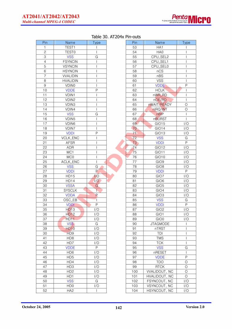
CONFI
DEN
TIAL
AT2041/AT2042/AT2043 Multi-channel MPEG-4 CODEC
October 24, 2005 Version 2.0 142
Table 30. AT204x Pin-outs Pin Name Type Pin Name Type
1 TEST1 I 53 HA1 I
2 TEST0 I 54 HA0 I
3 VSS G 55 CPU_SEL2 I
4 FSYNCIN I 56 CPU_SEL1 I
5 VSYNCIN I 57 CPU_SEL0 I
6 HSYNCIN I 58 nCS I
7 VVALIDIN I 59 nBS I
8 HVALIDIN I 60 VSS I
9 VDIN0 I 61 VDDE P
10 VDDE P 62 HCLK I
11 VDIN1 I 63 nWR_RD I
12 VDIN2 I 64 nOE/RD I
13 VDIN3 I 65 nWAIT/READY O
14 VDIN4 I 66 nIRQ/INT O
15 VSS G 67 nBIP I
16 VDIN5 I 68 nBURST I
17 VDIN6 I 69 GIO15 I/O
18 VDIN7 I 70 GIO14 I/O
19 VDDI P 71 GIO13 I/O
20 VCLK_ENC I 72 VSS G
21 AFSR I 73 VDDI P
22 ADR I 74 GIO12 I/O
23 MC1 I 75 GIO11 I/O
24 MC0 I 76 GIO10 I/O
25 ACLK_ENC I 77 GIO9 I/O
26 VSS G 78 GIO8 I/O
27 VDDI P 79 VDDI P
28 HD15 I/O 80 GIO7 I/O
29 HD14 I/O 81 GIO6 I/O
30 VSSA G 82 GIO5 I/O
31 SYSCLK I 83 GIO4 I/O
32 VDDA P 84 GIO3 I/O
33 OSC_EB I 85 VSS G
34 VDDI P 86 VDDI P
35 HD13 I/O 87 GIO2 I/O
36 HD12 I/O 88 GIO1 I/O
37 HD11 I/O 89 GIO0 I/O
38 VSS G 90 JTAGMODE I
39 HD10 I/O 91 nTRST I
30 HD9 I/O 92 TDI I
41 HD8 I/O 93 TMS I
42 HD7 I/O 94 TCK I
43 VDDE P 95 VSS G
44 HD6 I/O 96 nRESET I
45 HD5 I/O 97 VDDE P
46 HD4 I/O 98 TDO O
47 HD3 I/O 99 RTCK O
48 HD2 I/O 100 VVALIDOUT, NC O
49 HD1 I/O 101 HVALIDOUT, NC O
50 VSS G 102 FSYNCOUT, NC I/O
51 HD0 I/O 103 VSYNCOUT, NC I/O
52 HA2 I 104 HSYNCOUT, NC I/O

CONFI
DEN
TIAL
AT2041/AT2042/AT2043 Multi-channel MPEG-4 CODEC
October 24, 2005 Version 2.0 143
Pin Name Type Pin Name Type
105 VDOUT7, NC O 157 DDQM1 O
106 VDOUT6, NC O 158 VDDE P
107 VSS G 159 DDQM0 O
108 VDOUT5, NC O 160 DD31 I/O
109 VDOUT4, NC O 161 DD30 I/O
110 VDOUT3, NC O 162 DD29 I/O
111 VDOUT2, NC O 163 DD28 I/O
112 VDOUT1, NC O 164 VSS G
113 VDOUT0, NC O 165 VDDE P
114 VDDE P 166 DD27 I/O
115 VCLK_DEC, NC I 167 DD26 I/O
116 VDDI P 168 VSS G
117 AFSX I/O 169 VDDI P
118 ADX, NC O 170 DD25 I/O
119 VSS G 171 DD24 I/O
120 ACLK_DEC I 172 DD23 I/O
121 VDDI P 173 DD22 I/O
122 DA12 O 174 DD21 I/O
123 DA11 O 175 DD20 I/O
124 DA10 O 176 VSS G
125 VSS G 177 VDDI P
126 DA9 O 178 DD19 I/O
127 DA8 O 179 DD18 I/O
128 DA7 O 180 VSS G
129 DA6 O 181 DD17 I/O
130 VSS G 182 DD16 I/O
131 VDDI P 183 VDDI P
132 DA5 O 184 DD15 I/O
133 VDDE P 185 VDDE P
134 DA4 O 186 DD14 I/O
135 DA3 O 187 DD13 I/O
136 VDDI P 188 DD12 I/O
137 DCLK_FB I 189 VSS G
138 VSS G 190 VDDI P
139 DA2 O 191 DD11 I/O
140 DA1 O 192 DD10 I/O
141 DA0 O 193 DD9 I/O
142 VDDI P 194 DD8 I/O
143 DCLK O 195 VDDI P
144 VSS G 196 DD7 I/O
145 DBA1 O 197 DD6 I/O
146 DBA0 O 198 DD5 I/O
147 VDDE P 199 DD4 I/O
148 nDCAS O 200 VSS G
149 nDCS O 201 VDDE P
150 VSS G 202 DD3 I/O
151 nDRAS O 203 DD2 I/O
152 nDWE O 204 VSS G
153 DDQM3 O 205 DD1 I/O
154 VSS G 206 DD0 I/O
155 VDDI P 207 DCKE O
156 DDQM2 O 208 IDDQ I

CONFI
DEN
TIAL
AT2041/AT2042/AT2043 Multi-channel MPEG-4 CODEC
October 24, 2005 Version 2.0 144
Table 31. AT2042P Pinouts (BGA package) Pin Name Type Pin Name Type
A1 TEST1 I D2 HVALIDIN I
A2 DCKE O D3 VSS G
A3 DD2 I/O D4 VSS G
A4 DD3 I/O D5 VDDI P
A5 DD5 I/O D6 VSS G
A6 DD8 I/O D7 VDDI P
A7 DD11 I/O D8 VSS G
A8 DD14 I/O D9 VDDE P
A9 DD16 I/O D10 VDDE P
A10 DD17 I/O D11 VSS G
A11 DD19 I/O D12 VDDI P
A12 DD22 I/O D13 DD30 I/O
A13 DD25 I/O D14 VDDI P
A14 DD27 I/O D15 VSS G
A15 DD28 I/O D16 nDCAS O
A16 DDQM1 O D17 DBA0 O
A17 DDQM2 O E1 VDIN3 I
B1 FSYNCIN I E2 VDIN2 I
B2 TEST0 I E3 HSYNCIN I
B3 IDDQ I E4 VDDI P
B4 DD1 I/O E14 VSS G
B5 DD4 I/O E15 VSS G
B6 DD6 I/O E16 DCLK O
B7 DD9 I/O E17 DBA1 O
B8 DD12 I/O F1 VDIN7 I
B9 DD15 I/O F2 VDIN5 I
B10 DD18 I/O F3 VDIN0 I
B11 DD21 I/O F4 VSS G
B12 DD24 I/O F14 VDDI P
B13 DD26 I/O F15 VDDI P
B14 DD29 I/O F16 DA0 O
B15 DDQM0 O F17 DA1 O
B16 DDQM3 O G1 ADR I
B17 nDRAS O G2 VCLK_ENC I
C1 VVALIDIN I G3 VDIN4 I
C2 VSYNCIN I G4 VDDI P
C3 VSS G G14 VSS G
C4 DD0 I/O G15 DA2 O
C5 VSS G G16 DA3 O
C6 DD7 I/O G17 DCLK_FB I
C7 DD10 I/O H1 MC0 I
C8 DD13 I/O H2 MC1 I
C9 VDDE P H3 VDIN6 I
C10 DD20 I/O H4 VDDE P
C11 DD23 I/O H14 VDDE P
C12 VDDI P H15 DA4 O
C13 DD31 I/O H16 DA5 O
C14 VDDI P H17 DA6 O
C15 VSS G J1 HD14 I/O
C16 nDWE O J2 HD15 I/O
C17 nDCS O J3 AFSR I
D1 VDIN1 I J4 VDDE P

CONFI
DEN
TIAL
AT2041/AT2042/AT2043 Multi-channel MPEG-4 CODEC
October 24, 2005 Version 2.0 145
Pin Name Type Pin Name Type
J14 VDDE P P17 VDOUT1 O
J15 DA9 O R1 HD2 I/O
J16 DA8 O R2 HA2 I
J17 DA7 O R3 VSS G
K1 VSSA P R4 CPU_SEL2 I
K2 OSC_EB I R5 VDDI P
K3 ACLK_ENC I R6 VSS G
K4 SYSCLK I R7 nIRQ/INT O
K14 VDDE P R8 GIO14 I/O
K15 DA11 O R9 GIO11 I/O
K16 DA12 O R10 GIO6 I/O
K17 DA10 O R11 GIO1 I/O
L1 HD13 I/O R12 nTRST I
L2 HD11 I/O R13 VDDI P
L3 HD12 I/O R14 VVALIDOUT O
L4 VDDA P R15 VDOUT7 O
L14 VDDI P R16 VDOUT6 O
L15 VDDI P R17 VDOUT4 O
L16 AFSX I/O T1 HD0 I/O
L17 ACLK_DEC I T2 HA0 I
M1 HD10 I/O T3 HA1 I
M2 HD8 I/O T4 CPU_SEL0 I
M3 HD9 I/O T5 nWR_RD I
M4 VSS G T6 nOE/RD I
M14 VSS G T7 nBIP I
M15 VSS G T8 GIO13 I/O
M16 VCLK_DEC I T9 GIO10 I/O
M17 ADX O T10 GIO7 I/O
N1 HD7 I/O T11 GIO4 I/O
N2 HD4 I/O T12 GIO2 I/O
N3 HD5 I/O T13 TMS I
N4 HD3 I/O T14 TDO O
N14 VSS G T15 HVALIDOUT O
N15 VDOUT3 O T16 FSYNCOUT I/O
N16 VDOUT2 O T17 HSYNCOUT I/O
N17 VDOUT0 O U1 CPU_SEL1 I
P1 HD6 I/O U2 nCS I
P2 HD1 I/O U3 nBS I
P3 VSS G U4 HCLK I
P4 VSS G U5 nWAIT/READY O
P5 VDDI P U6 nBURST I
P6 VSS GG U7 GIO15 I/O
P7 VDDI P U8 GIO12 I/O
P8 VDDE P U9 GIO8 I/O
P9 GIO9 I/O U10 GIO5 I/O
P10 VDDE P U11 GIO3 I/O
P11 VDDE P U12 GIO0 I/O
P12 VSS G U13 JTAGMODE I
P13 VDDI P U14 TDI I
P14 VSYNCOUT I/O U15 TCK I
P15 VSS G U16 nRESET I
P16 VDOUT5 O U17 RTCK O

CONFI
DEN
TIAL
AT2041/AT2042/AT2043 Multi-channel MPEG-4 CODEC
October 24, 2005 Version 2.0 146
14. Package Information
14.1. Package Dimensions
208-pin plastic LQFP Dimensions in mm (inches).
Note: The values in parentheses are reference values.
Note 1) * : These dimensions do not include resin protrusion.
Note 2) Pins width and pins thickness include plating thickness.
Note 3) Pins’ widths do not include tie bar cutting remainder.

CONFI
DEN
TIAL
AT2041/AT2042/AT2043 Multi-channel MPEG-4 CODEC
October 24, 2005 Version 2.0 147
208-pin TBGA Dimensions in mm (inches)
Note: The values in parentheses are reference values.
TOP VIEW
BOTTOM VIEW SIDE VIEW

CONFI
DEN
TIAL
AT2041/AT2042/AT2043 Multi-channel MPEG-4 CODEC
October 24, 2005 Version 2.0 148
14.2. Re-flow Profile Guideline
Re-flow of AT204x LQFP208 package has restriction of operation until second run and inner 2
days after unsealing. Guideline of re-flow is shown below.
Guideline of re-flow for AT2042P TBGA208 Package is shown below.
Peak Temp. : Maximum 260degC
Dwell Time : 90+/-35sec over 217degC Melting Point
14.3. Pb-free Notification
Lead(Pb)-free packaging is applied for the AT204x devices in LQFP 208 package that the lot
number on the device’s surface are equal or more than ‘0502’. And all Pb-free devices are also
specified by adding an ‘E1’ mark to the device’s surface.
And all the AT2042 devices in TBGA package are Pb-free devices

CONFI
DEN
TIAL
AT2041/AT2042/AT2043 Multi-channel MPEG-4 CODEC
October 24, 2005 Version 2.0 149
15. Rx Parameters in Detail
15.1. Global Parameters (GID=0x0, CID=0x0)
‘Ack for Tx’ (PID=0x1) The AT204x outputs Tx message or data for reading, and then it shall wait until the host CPU
sends ‘ack for Tx’ parameter of host CPU. After receiving ‘ack for Tx’ parameter, the AT204x should
de-assert the interrupt signal and then clear all data in Tx FIFO. If the host CPU doesn’t send ‘ack
for Tx’ parameter, the AT204x won’t output data or message anymore.
‘Operation mode’ (PID=0x2) The operation mode of the AT204x is decided by this parameter. There are 3 operation modes
in the AT204x as following;
Encoder mode (1): Encoder Only
CODEC mode (2): Full-duplex CODEC
Decoder mode (3): Decoder Only
Because the parameter is one of the global parameters related to SDRAM configuration, it
must be set up with other global parameters above all after booting of the AT204x. And the host
CPU cannot read and write this parameter after setting other general parameters. (Refer to Section
10.3.3)
‘SDRAM Size’ (PID=0x3) The size of SDRAM can be set up in the unit of Mbits. The necessary size of SDRAM depends
on the ‘operation mode’ (GID=0x0,PID=0x2), the ‘channel size’ (GID=0x0,PID=0x5) and the
‘maximum GOPM’ (GID=0x0,PID=0x5). (Refer to the Section 7.3)
Because this parameter also belongs to the global parameter regarding SDRAM configuration,
it must be set up in advance and it cannot be read/written after setting other parameters. (Refer
to Section 10.3.3)
‘Channel size’ (PID=0x5) It means the number of channels to be processed. And it can be set to 16 maximally because
the AT204x can handle the multiple channels processing up to 16 channels.
CONFI
DEN
TIAL
AT2041/AT2042/AT2043 Multi-channel MPEG-4 CODEC
October 24, 2005 Version 2.0 150
Because this parameter belongs to the global parameter regarding SDRAM configuration, it
must be set up in advance and it cannot be read/written after setting other parameters. (Refer to
Section 10.3.3)
‘Maximum GOPM’ (PID=0x6) User can select the GOP structure for encoding and decoding operation. According to the
‘maximum GOPM’ parameter, the available GOP structures are as following;
3: IBBPBBP…, IBPBP…, IPPP…, III…
2: IBPBP…, IPPP…, III…
1: IPPP…, III…
And the AT204x may skip the decoding operation of B-Picture which cannot be decoded.
Because this parameter also belongs to the global parameter regarding SDRAM configuration,
it must be set up in advance and it cannot be read/written after setting other parameters. (Refer
to Section 10.3.3)
‘Host interface signal control’ (PID=0x10) This parameter can be used to select the operation mode of the nWAIT/READY and the
nIRQ/INT signals in host interface signals. And it is recommended the setting of the parameter
during initialization operation once for all.
Wait (nWAIT/READY) active pull-up or pull-down
When the nWAIT/READY signal is changed to inactive state in the active mode (1), the
AT204x maintains the signal level of inactive state during 1 clock period before it drives
the nWAIT/READY signal to high-Z state. On the other hand, if user selects the normal
mode (0), the nWAIT/READY signal becomes to high-Z state immediately after active
period is completed, and it changes to inactive state according to pull-up or pull-down
register. Therefore the active mode is favorable for the high-speed operation. But the
nWAIT/READY is operated in the normal mode before the firmware is uploaded and the
default value after uploading is the active mode. So user can change the mode after
uploading the firmware.
Wait (nWAIT/READY) polarity inverse
In case of value ‘0’, the polarity of the nWAIT/READY signal observes a polarity value in
the Table 14. But if user sets this parameter to ‘1’, the nWAIT/READY signal has an
opposite polarity of the Table 14.
Interrupt (nIRQ/INT) polarity inverse

CONFI
DEN
TIAL
AT2041/AT2042/AT2043 Multi-channel MPEG-4 CODEC
October 24, 2005 Version 2.0 151
In case of value ‘0’, the polarity of the nIRQ/INT signal observes a polarity value in the
Table 14. But if user sets this parameter to ‘1’, the nIRQ/INT signal has an opposite
polarity of the Table 14.
‘GIO Mode’ (PID=0x12) The operation mode of GIO[15:8] shall be decided by this parameter. User can select the
mode of GIO[15:8] among below 3 modes.
User control mode (0)
In this mode, user can set the mode of each GIO pin to input or output by ‘GIO direction’
(GID=0x0,PID=0x13). And user may input some data via input pin or output via output
pin by using ‘GIO data’ (GID=0x0,PID=0x14)
Debug mode (1)
This mode is very useful in debugging stage because user may get the debugging
information via GIO[15:8]. In this mode, GIO[8] will be toggled with about 1Hz frequency
in normal situation. But it may be not toggled in case the firmware is in abnormal state. In
case the AT204x is waiting for ‘ack for tx’ (GID=0x0,PID=0x1) parameter, GIO[9] will be
‘1’. Otherwise the AT204x will output ‘0’ value via GIO[9]. And the AT204x will output ‘1’
value via GIO[10] while it is waiting for ‘ack for data ready’ (GID=0x1, PID=0x1) or ‘alt
ack for data ready’ (GID=0x1,PID=0x30) parameter, and it will output ‘0’ in other case. In
case of GIO[11], it will only output ‘1’ value while it is waiting for ‘ack for data request’
(GID=0x2, PID=0x1) or ‘alt ack for data ready’ (GID=0x2, PID=0x30) parameter. Note
that GIO[15:12] will be automatically set to input mode and will have ‘0’ value in this
mode.
GIO channel ID interface mode (2)
This parameter is only effective for ’Channel ID interface mode’ (GID=0x4, PID=0xC) of
128~131. By the mode, user can utilize GIO[15:8] for channel ID interface.
‘GIO direction’ (PID=0x13) In case ‘GIO mode’ (GID=0x0,PID=0x12) is ‘0’, user can select GIO[15:8] to input or output
mode. If Dir[n] is ‘0’, GIO[8+n] will be set to input mode. Otherwise it will be set to output mode.
Note that ‘n’ has the value between 0 and 7.
‘GIO data’ (PID=0x14) In case ‘GIO mode’ (GID=0x0,PID=0x12) is ‘0’, the AT204x reads or writes data via GIO[15:8]

CONFI
DEN
TIAL
AT2041/AT2042/AT2043 Multi-channel MPEG-4 CODEC
October 24, 2005 Version 2.0 152
pins according to ‘GIO direction’ (GID=0x0, PID=0x13). In the write operation, data[n] will be
output via GIO[8+n] while mask[n] is ‘1’. But if mask[n] is ‘0’, GIO[8+n] will maintain the previous
values regardless of data[n]. In the read operation, data[n] will indicate the reading values by
GIO[8+n], and the pins to be set to input modes are only effective. Note that mask[7:0] will be
read to ‘0xFF’ and ‘n’ has the value between 0 and 7.
‘Operation mode 2’ (PID=0x20) This is the second parameter for AT204x operation mode. By this parameter, user can select
the mode as following.
Normal mode (0)
The AT204x will perform the general encoding and decoding operation.
Trans-coding mode (1)
The AT204x can perform the low-level trans-coding function which applies re-encoding
technology of decoded raw video from encoded bitstream. So user can change all kinds of
encoding parameters such as compression standard, resolution, video quality, frame rate,
GOP structure and etc. And this mode can be applied in case ‘operation mode’ (GID=0x0,
PID=0x2) is ‘1’(CODEC mode) only. The detailed information about the trans-coding mode
are described in the AT204x_AN13_ExtraFunctions_Vxx(Eng).pdf.
2-way encoding mode (2)
By using 2-way encoding mode, AT204x can handle the encoding operation in D1@25Hz
and CIF@25FPS at the same time. When the AT204x receives the D1 resolution video with
physical channel ID of ‘N’, it can generate two compressed streams of the channel ‘N’ with
D1 resolution and the channel ‘N+1’ with low resolution. And the resolution of the second
channel can be selected by ‘2-way encoding scale mode’ (GID=0x5, PID=0x30) parameter.
Though the AT204x can provide the encoding of 30FPS for D1 resolution in the normal
mode, it can encode video data with 25FPS for D1 resolution and with 25FPS for CIF
resolution simultaneously. But there are some restrictions in the 2-way encoding mode.
Because the full-duplex function does not provide in the mode, user can only utilize for
encoding-only mode (half-duplex function). And B-VOP will be prohibited for the second
channel (scaled channel), and the monitoring function of input video won’t be provided.
The detailed information about the 2-way encoding are described in the
AT204x_AN13_ExtraFunctions_Vxx(Eng).pdf.

CONFI
DEN
TIAL
AT2041/AT2042/AT2043 Multi-channel MPEG-4 CODEC
October 24, 2005 Version 2.0 153
‘Global status’ (GID=0x0,PID=0x30) data ready status
While the AT204x is waiting for ack for data ready’ (GID=0x1,PID=0x1) or ‘alt ack for data
ready’ (GID=0x1,PID=0x30) parameter, it will write the value of ‘1’ to this register.
Otherwise this register will indicate the value of ‘0’.
data request status
While the AT204x is waiting for ‘ack for data request’ (GID=0x2,PID=0x1) 또는 ‘alt ack
for data request’ (GID=0x2,PID=0x30) parameter, it will write the value of ‘1’ to this
register. Otherwise this register will indicate the value of ‘0’.
15.2. Encoder System Parameters (GID=0x1, CID=0x0)
‘Acknowledge for data ready message’ (PID=0x1) Because this is an obsolete parameter, the 'alt. ack. for data ready message' (GID=1,
PID=0x30) is strongly recommended. And this parameter is available when the 'encoder
acknowledge mode' (GID=1, PID=0x31) should be set to the value of ‘0’(default). To apply the 'alt.
ack. for data ready message' (GID=1, PID=0x30), the 'encoder acknowledge mode' (GID=1,
PID=0x31) should be set to the value of ‘1’. After the AT204x issues ‘data ready message’
(GID=0x1, MID=0x1), the host CPU should transfer ‘ack for data ready’ (GID=0x1, PID=0x1) or
‘alt ack for data ready’ (GID=0x1, PID=0x30) parameter to the AT204x after reading data of the
informed size. If not, the AT204x won’t issue the next ‘data ready message’ (GID=0x1, MID=0x1)
anymore.
‘Encoder start’ (PID=0x2)
Video encoder start
The video encoding operation will be started by writing ‘1’ to this parameter. But the
AT204x will be in the idle state when the value ‘0’ is written. By reading the parameter, the
host CPU can perceive the operation status of the video encoder. The value has ‘1’ during
the encoding operation and ‘0’ during encoding stop.
Audio encoder start
The audio encoding operation will be started by writing ‘1’ to this parameter. But the
AT204x will be in the idle state when the value ‘0’ is written. By reading the parameter, the
host CPU can perceive the operation status of the audio encoder. The value has ‘1’ during

CONFI
DEN
TIAL
AT2041/AT2042/AT2043 Multi-channel MPEG-4 CODEC
October 24, 2005 Version 2.0 154
the encoding operation and ‘0’ during encoding stop.
‘Encoder stop’ (PID=0x3)
Video encoder stop
The video encoding operation will be stopped by writing ‘1’ to this parameter. But the
AT204x will be in the idle state when the value ‘0’ is written.
Audio encoder stop
The audio encoding operation will be stopped by writing ‘1’ to this parameter. But the
AT204x will be in the idle state when the value ‘0’ is written.
‘Output stream format’ (PID=0x4) The AT204x provides 2 kinds of stream formats as following;
PES (2): Packetized Elementary Stream.
TS (3): Transport Stream.
More detailed information about the stream format have described in the application notes as
follows.
AT204x_AN12_StreamFormat_Vxx(Eng).pdf
AT204x_AN01_PS_Type1_Vxx(Eng).pdf
Standard document for MPEG-2 system (ISO/IEC 13818-1)
‘Maximum output data size’ (PID=0x5) The parameter is to prescribe a maximum data size with the unit of Kbytes which can output
by one ‘data ready message’ (GID=0x1, MID=0x1). When the size of encoded data for a frame is
more than the predefined size, the AT204x outputs the data after dividing to several parts. By
using ‘last flag’ in ‘data ready message’ (GID=0x1, MID=0x1), the AT204x informs the host CPU
which one is the last part of one frame data. For example, if user selects 30Kbytes for the
‘maximum output data size’, the data of 100Kbytes outputs in 4 times with the ‘last flag’ of ‘0’ for
the first 3 messages and ‘1’ for the last massage.
The host CPU should correspond with different method according to ‘encoder acknowledge
mode’ (GID=0x1, PID0x31). In case of ‘Encoder acknowledge mode’ of ‘0’, the host CPU should
send ‘ack for Tx’ (GID=0x0, PID=0x1) only after reading data with the ‘last flag’ of ‘0’, and should
send ‘ack for Tx’ (GID=0x0, PID=0x1) and ‘ack for data ready message’ (GID=0x1, PID=0x1) after
reading data with the ‘last flag’ of ‘1’. But, in case of ‘Encoder acknowledge mode’ of ‘1’, it should
always send ‘ack for Tx’ (GID=0x0, PID=0x1) and ‘alternative ack for data ready message’

CONFI
DEN
TIAL
AT2041/AT2042/AT2043 Multi-channel MPEG-4 CODEC
October 24, 2005 Version 2.0 155
(GID=0x1, PID=0x30) regardless of the ‘last flag’ in ‘data ready message’ (GID=0x1, MID=0x1).
‘Alternate acknowledge for data ready message’ (PID=0x30)
After receiving ‘data ready message’ (GID=0x1, MID=0x1) from the AT204x, the host CPU
should read the data of the informed size and send ‘alternative ack for data ready message’
parameter to the AT204x. Otherwise the AT204x won’t generate ‘data ready message’ (GID=0x1,
MID=0x1) anymore.
When the host CPU cannot read any data after receiving ‘data ready message’ (GID=0x1,
MID=0x1), it should send ‘alternative ack for data ready message’ parameter with the ‘null flag’ of
‘1’. If the AT204x receives the parameter, it will generate the same ‘data ready message’ once
again after about 10msec. Just for reference, the 'encoder acknowledge mode' (GID=1,
PID=0x31) should be set to ‘1’ for the use of 'alternative ack. for data ready message' (GID=1,
PID=0x30).
'Encoder acknowledge mode' (PID=0x31) This parameter should be set to ‘0’ for ‘ack. for data ready message’ (GID=0x1, PID=0x1)
parameter and ‘1’ for ‘alternative ack. for data ready message’ (GID=0x1, PID=0x30) parameter.
Because the 2 acknowledge parameters cannot use at a time, the host CPU must select one
method by the ‘encoder acknowledge mode’ (PID=0x31).
15.3. Encoder Video Parameters (GID=0x4, CID=0x0)
‘Input video format’ (PID=0x1) The desired format for video input format can be selected by this parameter.
Horizontal size
Horizontal size of input video is defined in a pixel unit.
Vertical size
Vertical size of input video is defined in a line unit.
Input video rate code
Frame rate or field rate of input video can be selected by this parameter. It indicates the
frame rate for the ‘field mode’ of ‘0’ and the field rate for the ‘field mode’ of ‘1’. And it is
irrelevant to the channel because it is a total frame or field rate. If user sets the parameter
to different value from input video, the AT204x might not encode or generate stream with
abnormal ‘time code’.

CONFI
DEN
TIAL
AT2041/AT2042/AT2043 Multi-channel MPEG-4 CODEC
October 24, 2005 Version 2.0 156
Field mode
User should set the parameter to ‘1’ for the field-based encoding or ‘0’ for the frame-
based encoding.
‘Input video clock inversion’ (PID=0x2) The polarity of video input clock (VCLK_ENC) is programmable through the parameter.
‘Input video sync mode’ (PID=0x3) This parameter defines the sync format of input video as follows.
Normal embedded sync mode (0)
It is ITU-R BT.656 8-bit YCbCr 4:2:2 data format with embedded sync data of SAV and EAV.
In this mode, the default value is used for ‘video input sync polarity’ (GID=0x4, PID=0x8)
parameter. And a pull-up is required for the VVALIDIN and HVALIDIN pins.
External sync mode (2)
It is a synchronous 8-bit YCbCr 4:2:2 data format with separate 5 sync signals such as
FSYNC, VSYNC, HSYNC, VVALID and HVALID signal. The HVALID always has consecutive
valid timing in a line. The AT204x cannot accept the video data with discontinuous valid
timing in the HVALID signal.
‘Vertical offset mode’ (PID=0x4) When ‘input video sync mode’ (GID=0x4, PID=0x3) is ‘0’, user can select vertical offset value
for input video. If user set this parameter to ‘0’, the AT204x captures the input video in accordance
with ITU-R BT.656 standard. In case of the value of ‘1’, the below ‘vertical offset value’ (GID=0x4,
PID=0x0x5) parameter is applied to the input video capture.
‘Vertical offset value’ (PID=0x0x5) When ‘vertical offset mode’ (GID=0x4, PID=0x4) is ‘1’, this offset value is used for the capture
of active video in encoding operation. It means the offset value between the edge of FSYNC and
the start of the active line. User can set the parameter for each field differently and the minimum
value is ‘19’ for even field and ‘18’ for odd field. Please refer to Section 11.1.1 for details.
‘Field sync mode’ (PID=0x6) This parameter is available only when ‘input video sync mode’ (GID=0x4, PID=0x3) has the
value of ‘2’. When the parameter is ‘0’, the AT204x identifies the field by the FSYNC signal. If user
set the parameter to ‘1’, the field is discriminated with reference to the HSYNC and VSYNC

CONFI
DEN
TIAL
AT2041/AT2042/AT2043 Multi-channel MPEG-4 CODEC
October 24, 2005 Version 2.0 157
according to ‘first field decision parameter’ (GID=0x4, PID=0x7).
‘First field decision parameter’ (PID=0x7)
In the ‘field sync mode’ (GID=0x4,PID=0x6) of ‘1’, the AT204x obtains the field information by
using the distance between the starts of VSYNC and HSYNC. This parameter means the number of
clocks between 2 sync signals. If the distance is equal or less than the parameter in this register,
the AT204x recognizes as the first field. Otherwise it recognizes as the second field. Please refer to
Section 11.1.2 for details.
‘Video input sync polarity’ (PID=0x8) In the ‘input video sync mode’ (GID=0x4, PID=0x3) of ‘2’, the polarities of sync signals can be
determined by this parameter. When the ‘input video sync mode’ is ‘0’, the default values are
applied. Please refer to Section 11.1.3 for details.
‘Input video data saturation value’ (PID=0x09) Minimum value of luminance data
If the signal level of luminance is less than this value, it is rounded up to this level.
Maximum value of luminance data
If the signal level of luminance is more than this value, it is rounded down to this level.
Minimum value of chrominance data
If the signal level of chrominance is less than this value, it is rounded up to this level.
Maximum value of chrominance data
If the signal level of chrominance is more than this value, it is rounded down to this level.
‘Preprocessing filter control’ (PID=0xA) The low pass filter and median filter are turned on or turned off by this parameter.
‘Input video shift-right size’ (PID=0xB) The offset value for video capture can be controlled to 12 pixels into 4-pixel unit. And the left
pixels after shifting are filled with garbage data. This parameter is useful for the alignment in 16-
pixel unit for the spatial multi-channel encoding.
‘Channel ID interface mode’ (PID=0xC) There are 2 kinds of channel ID interface modes according to the fetch time. In the normal
encoding, ‘current mode (0)’ is generally used. But ‘next mode (1)’ should be selected for multi-

CONFI
DEN
TIAL
AT2041/AT2042/AT2043 Multi-channel MPEG-4 CODEC
October 24, 2005 Version 2.0 158
channel encoding in different resolutions for each channel because different scale-down filters are
applied for each channel.
Current mode (0)
In case the channel ID interface by VBI is applied, the related channel ID should be placed
at the VBI in the front of active video data. But channel ID should be input during the
input period of current video data for GIO channel ID interface.
Next mode (1)
In case the channel ID interface by VBI is applied, the related channel ID should be placed
at the VBI in 2 fields ahead of current video data. For GIO channel ID interface, channel
ID should be input during the video input period in 2 fields ahead of current video data.
The AT204x supports the interface with various multiplex devices. The usages of channel ID
interface modes for multiplex devices are described at the table in Section 10.6.3. In the table,
‘custom mode 7 (70)’ and ‘custom mode 8 (71)’ are to interface with TECHWELL’s TW2834. In
case of the ‘custom mode 7’, the AT204x fetches the channel ID at CASCADE and VIN_PATH in the
auto channel ID information of the TW2834 device. And it fetches at ANAPATH and VIN_PATH for
the ‘custom mode 8’. Therefore user may apply the ‘custom mode 7’ up to 16-channel system by
multiple TW2834 devices. And the ‘custom mode 8’ may be suitable up to 8-channel system by
one TW2834 device.
To use the GIO channel ID interface mode of 1~4, ‘GIO mode’ (GID=0x0, PID=0x12) should
be set to ‘2’. Please refer to the AT204x_AN05_ChannelID_Vxx(Eng).pdf for more detailed
information regarding channel ID interface.
‘Watermark enable’ (PID=0xD) The watermark function can be enabled (1) or disabled (0) by the parameter.
‘Watermark strength’ (PID=0xE) The strength of watermark embedding can be adjusted by the parameter. Higher values would
provide severer watermarking, but the picture quality may be affected. On the contrary, lower
values would provide feebler watermarking and better picture quality
‘Watermark key’ (PID=0xF) The parameter is a key value with the size of 16 bytes for watermark generation.

CONFI
DEN
TIAL
AT2041/AT2042/AT2043 Multi-channel MPEG-4 CODEC
October 24, 2005 Version 2.0 159
‘Reference picture selection’ (PID=0x11) Last I/P-picture reference mode (0)
A P-Picture is predicted from a past I-Picture or P-Picture in accordance with MPEG
standard.
Last I-picture reference mode (1)
To prevent error propagation in a GOP, all P-Picture in a GOP are predicted from a past I-
Picture only. So this mode is useful in network streaming application. Of course, ‘reference
picture selection’ (GID=0x8, PID=0x24) parameter should be set to ‘last I-picture
reference mode (1)’ for decoding of encoded stream by this mode. And the stream cannot
be decoded in standard MPEG decoder because the mode does not comply with MPEG
standard.
‘Dummy channel ID’ (PID=0x14) This parameter is intended to set the physical channel ID that user doesn’t want to encode.
The AT204x doesn’t encode the channel with the same physical channel ID as ‘dummy channel ID’
(In case there are several channel IDs in a frame, the foremost channel ID is adopted). So this
parameter can be also applied as a tool of recording frame rate control. When the parameter is set
to ‘0x10’, the AT204x encodes all input channels without any dummy channel. In case ‘channel ID
interface mode’ (GID=0x4, PID=0xC) is equal or less than the value of ‘3’, the default value of the
parameter is ‘0x0F’. Otherwise the default value will be ‘0x10’.
‘Motion detection information output mode’ (PID=0x15) When this parameter is set to ‘1’, all motion information in 2x2 macroblock unit are embedded
in the PES header of compressed stream regardless of ‘motion detection area bitmap’ (GID=0x5,
PID=0x27). And to detect the motion, the AT204x refers to the parameters such as sensitivity,
pixel difference threshold and different pixel count threshold in ‘motion detection parameters’
(GID=0x5, PID=0x26).
But in case the parameter is set to ‘0’, the AT204x does not generate motion information in
the PES header. For more information, please refer to the AT204x_AN01_PS_Type1_Vxx(Eng).pdf.
‘Encoding offset mode’ (PID=0x16) There are 2 kinds of the encoding region selection methods for the spatial multi-channel
encoding.
Fixed offset mode (0)

CONFI
DEN
TIAL
AT2041/AT2042/AT2043 Multi-channel MPEG-4 CODEC
October 24, 2005 Version 2.0 160
The offset and size of encoding region can be selected by ‘encoding region information’
(GID=0x5, PID=0x23) parameter.
Dynamic offset mode (1)
The offset value of encoding region can be defined according to the reading order of
channel ID via VBI or GIO by using ‘1st ~ 4th dynamic offset value’ (GID=0x4,
PID=0x17~0x1A) parameter. And the size for each channel can be differently defined by
‘encoding region information’ (GID=0x5, PID=0x23). In this mode, the offset value in
‘encoding region information’ is ignored.
‘1st ~ 4th dynamic offset value’ (PID=0x17~0x1A) This parameter is available only when ‘encoding offset mode’ (GID=0x4, PID=0x16) is
dynamic offset mode (1). The offset value for each encoding region can be selected according to
the reading order of channel ID via VBI or GIO. For example, the offset value of the second
channel ID in VBI is defined by ‘2nd dynamic offset value’ (GID=0x4,PID=0x18).
And user can select the offset in 16-pixel unit horizontally and 2-pixel unit vertically. Therefore
user should note that the offset values might be dislocated to split area. In case of horizontal 2-
split mode (360x2), the encoding position of the left region is not coincided with that of the right
region because the horizontal size of each region is not a multiple of 16 pixels. To adjust the
discrepancy, the encoding start position of the right region should be shifted to the left or right
direction in 16-pixel unit.
‘Recording frame rate control mode’ (PID=0x1B) There are two kinds of recording frame rate control modes, as follows.
Recording frame rate control mode 0 (0)
User can control recording frame rate by using the ‘recording frame rate control mode 0’
(GID=0x5,PID=0x24) parameter.
Recording frame rate control mode 1 (1)
User can control recording frame rate by using the ‘recording frame rate control mode 1’
(GID=0x5,PID=0x28) parameter.
‘Time code’ (PID=0x20) User can initialize the time code that includes GOP header of MPEG-1/2 or GOV header of
MPEG-4. And the next time codes are increased at every FSYNC or VSYNC of video input in
consideration of ‘video input rate code’ in ‘input video format’ (GID=0x4, PID=0x1).

CONFI
DEN
TIAL
AT2041/AT2042/AT2043 Multi-channel MPEG-4 CODEC
October 24, 2005 Version 2.0 161
‘Q range in CBR mode’ (PID=0x25) In case ‘rate control mode’ (GID=0x5,PID=0x4) is picture level rate control mode (1) or MB
level rate control mode (2), the quantizer levels can be controlled within the range of value
between Qmin and Qmax.
15.4. Encoder Video Channel Parameters (GID=0x5, CID=Channel ID)
All parameters in this Section can be differently set up for each channel by CID value
‘Pause & Restart’ (PID=0x1) During encoding operation, the AT204x stops encoding when this parameter is set to ‘0’. And
to restart encoding, this parameter should be set to ‘1’. In case the parameter is set to ‘1’ before
encoding, the AT204x doesn’t encode for the channel though user transfers ‘encoder start’
(GID=0x1, PID=0x2) command. Of course, setting to ‘1’ can start the encoding operation.
‘Encoding standard’ (PID=0x3) This parameter is to select video encoding standard among the following standards.
JPEG (0)
MPEG1 (1)
MPEG2 (2)
H.263 (3)
MPEG4 (4)
‘Rate control mode’ (PID=0x4) Three methods are available for rate control method in the AT204x. But user can only utilize
the ‘Fixed Q’ algorithm for JPEG encoding.
Fixed Q (0)
This is a kind of VBR (variable bit rate) algorithm that a fixed quantizer level is applied to
encoding operation. Though user may get the compressed stream in constant picture
qualities, the data sizes for encoding frames may be extremely fluctuated according video
characteristics. The quantizer value can be selected by ‘Q value’ (GID=0x5, PID=0x5)
parameter.
Picture level rate control (1)
This is a kind of CBR (constant bit rate) algorithm which updates the quantizer levels

CONFI
DEN
TIAL
AT2041/AT2042/AT2043 Multi-channel MPEG-4 CODEC
October 24, 2005 Version 2.0 162
automatically according to a selected data rate. Though average data rates are preserved
to constant quantity, the picture qualities of encoded video are decreased in case the
video has complicated contents or several objects with large motion. But the AT204x may
not meet with the user-selected data rate when it is confronted by exceedingly
complicated or simple video. In this mode, the fluctuation of picture qualities is less than
that of MB level rate control method because the quantizer levels are updated in GOP unit.
And the data rate can be selected by ‘rate control parameters’ (GID=0x5, PID=0x6).
MB level rate control (2)
This mode is also a kind of CBR modes which can control the quantizer level in macroblock
unit. In this mode, user can get the compressed stream with almost same bit rate on
regardless of video characteristics. But the picture qualities may be decreased while
complicated video is input. But the AT204x may not meet with the user-selected data rate
when it is confronted by exceedingly complicated or simple video. Because the quantizer
level of each macroblock can be renewed, the data rate can be maintained to the selected
quantity and on the other hand the picture quality may be fluctuated excessively. And the
data rate can be selected by ‘rate control parameters’ (GID=0x5, PID=0x6).
‘Q value (image quality for JPEG)’ (PID=0x5) The quantizer level is set up by this parameter when ‘Rate control mode’ (GID=0x5, PID=0x4)
is the fixed Q mode (0). The levels for JPEG encoding range from 1% to 100%, and user should
apply a high level to compression with good picture quality. In other standards, the levels have a
range of 1~31, the lower level is selected for high quality encoding.
‘Rate control parameters’ (PID=0x6) When ‘Rate control mode’ (GID=0x5, PID=0x4) is set to Picture level rate control (1) or MB
level rate control (2), an average bit rate for a frame should be selected in the multiple of 1,000
bits. But the sizes of encoded data shall be a little more or less than the selected value according
to input video characteristics.
‘GOP structure’ (PID=0x7) A GOP structure shall be determined in all standards, excluding JPEG standard.
And the AT204x provides 3 types of GOP structure as following.
Open GOP (0)
The first B-VOPs immediately following the first coded I-VOP in a GOP shall be encoded by

CONFI
DEN
TIAL
AT2041/AT2042/AT2043 Multi-channel MPEG-4 CODEC
October 24, 2005 Version 2.0 163
referring the two most recently reconstructed reference frames (forward, backward
prediction or intra coding). In this mode, the first B-VOPs will be broken during the editing
in a GOP.
Closed GOP (1)
The first B-VOPs immediately following the first coded I-VOP in a GOP shall be encoded
using only backward prediction (I-VOP in the same GOP) or intra coding. It is provided for
use during any editing, which occurs after encoding.
Closed GOP type 2 (2)
The AT204x doesn’t encode the first B-VOPs between I-VOP and P-VOP because some
DivX player cannot usually decode them. The editing operation in a GOP unit is possible by
this mode like the Closed GOP type 1 (1).
The GOP structure shall be decided by GOP_NM and GOP_M values. The GOP_NM means the
value which divides N (the distance between the two consecutive I-VOPs) by M (the distance
between I-VOP (or P-VOP) and the successive P-VOP (or I-VOP). And the GOP_M is the same as
the above M. The value of the GOP_M can be selected the range of 1~3, and it must be equal or
less than ‘Maximum GOPM’ (GID=0x0, PID=0x6).
Just for information, the GOP_M should be internally set to ‘1’ independently of the setting
value because B-VOP is not available in H.263 standard and MPEG-4 Simple Profile (‘MPEG
encoding parameter’ (GID=0x5,PID=0xB)).
‘Force I’ (PID=0x8) User can force the picture coding type to I-VOP. For example, if user sends the ‘force I’
parameter during encoding operation with GOP_NM = 10 and GOP_M = 1, the GOP structure will
be changed as follows.
… I P P P P P P P P P I P P P P [force I] I P P P P P P P P P P I P P P …
When the AT204x receives the ‘force I’ parameter, it immediately creates a new GOP after
quitting the current GOP structure.
‘Re-sync mode’ (PID=0x9) This is a valid parameter for JPEG, H.263 and MPEG-4 standard. User can decide whether or
not insert the re-sync code, and select the insertion method. Usually the re-sync code is used to
confine error propagation area to a limited area in error-prone environment.
re-sync off (0)
CONFI
DEN
TIAL
AT2041/AT2042/AT2043 Multi-channel MPEG-4 CODEC
October 24, 2005 Version 2.0 164
The re-sync code shall not be used.
re-sync interval mode (1)
The re-sync codes shall be inserted into every data with the given size by ‘re-sync interval’
(GID=0x5, PID=0xA) parameter. This mode is only available for MPEG-4 standard.
slice re-sync mode (2)
The re-sync code shall be only inserted at the leftmost macroblock in a slice.
‘Re-sync interval’ (PID=0xA) A re-sync interval can be decided in 2 bytes unit only when ‘re-sync mode’ (GID=0x5,
PID=0x9) is set to re-sync interval mode (1) in MPEG-4 standard. Because it’s impossible to insert
at exact position, the re-sync code will be added every data of similar size to this parameter.
‘MPEG encoding parameters’ (PID=0xB) Adaptive quantization
This parameter is available only when ‘rate control mode’ (GID=0x5, PID=0x4) is MB level
rate control mode (2). In case the parameter is selected, the AT204x shall encode with
lower quality for complicated area and higher quality for smooth area. So the subjective
quality shall be increased by the adaptive quantization.
The detailed information regarding other parameters are described in the MPEG standard
document (ISO/IEC 13818-2, 14496-2).
‘Reaction parameter in CBR mode’ (PID=0xC) The alteration speed of quantizer level according to input video characteristic can be
controlled only when ‘Rate control mode’ (GID=0x5, PID=0x4) is set to MB level rate control mode
(2). In case of higher ‘react’ (=(react_a + 1)/(react_b + 1)) value, the data variation according to
video characteristic shall be minimized because the AT204x would encode with faster alteration of
quantizer level. But it is unavoidable that the picture qualities may be changed quickly. On the
contrary, the lower value shall lead to slower alteration of quantizer level and larger variation of
data rate.
‘Encoding video stream_id’ (PID=0x1F) User can define the stream ID of video PES packet. The stream ID shall be (0xD0 +
stream_id) for JPEG standard and (0xE0 + stream_id) for other standards including MPEG-4.
Basically ‘stream_id’ has the same value as the ‘logical channel ID’. Please refer to the description
of ‘Physical Channel ID assign’ (GID=0x5, PID=0x20) for details regarding the ‘logical channel ID’

CONFI
DEN
TIAL
AT2041/AT2042/AT2043 Multi-channel MPEG-4 CODEC
October 24, 2005 Version 2.0 165
‘Physical Channel ID assign’ (PID=0x20) User should select the ‘physical channel ID’ to be encoded by specific ‘logical channel’. The
‘physical channel ID’ means the channel ID that is input via VBI or GIO. And the same manner
shall be also applied in case several channel IDs are input via VBI or GIO. The ‘logical channel’
means a virtual channel for encoding, and the AT204x performs the encoding operation with the
‘logical channel ID’. Therefore the number of the ‘logical channel’ is the same as the value of
‘channel size’ (GID=0x0, PID=0x5), and the ‘logical channel ID (CID) has the value within the
range of 0 ~ (‘channel size’-1). In case the ‘channel size’ is 4 and the ‘physical channel ID’ has the
value of 4 ~ 7, the ‘logical channel ID’ should be assigned as follows.
Logical channel ID(CID) Physical channel ID
0 4
1 5
2 6
3 7
In this case, the stream shall be created with the stream ID of 0xE0~0xE3. To change the
stream IDs to 0xE4~0xE7, the ‘stream_id’ of logical channels should be modified by ‘encoding
video stream_id’ (GID=0x5, PID=0x1F) as bellows.
Logical channel ID (CID) stream_id
0 4
1 5
2 6
3 7
Just for reference, one ‘physical channel ID’ can be assigned to multiple ‘logical channel IDs’,
and one input channel shall be encoded to several channels in this case. For example, when
physical channel 0 is assigned to logical channel 0 for MPEG-4 and channel 1 for JPEG, the AT204x
shall encode one input video channel to dual-streams of MPEG-4 and JPEG at the same time.
‘Video Loss’ (PID=0x21) By using channel loss information from other devices such as video decoder or quad/mux

CONFI
DEN
TIAL
AT2041/AT2042/AT2043 Multi-channel MPEG-4 CODEC
October 24, 2005 Version 2.0 166
device, user can control whether or not encode the video channel. If user set this parameter to ‘1’
while the video channel is in loss state, the AT204x doesn’t encode it anymore. In this case, the
AT204x will issue ‘data ready message’ (GID=0x1, MID=0x1) with ‘loss flag’ of ‘1’ and ‘output data
size’ of ‘0’. Of course, this parameter should be set to ‘0’ to resume encoding.
Just for reference, the AT204x doesn’t provide an internal video loss detection function.
Therefore the detection of video loss should be performed in other external device, and the
AT204x only control the encoding ON/OFF operation by using the information.
‘Input video scale mode’ (PID=0x22) Various scale-down filters for input video can be selectively used by this parameter. There are
3 horizontal filters (1(0), 8/9(1), 1/2(2), 4/9(3)) and 1 vertical filter (1(0), 1/2(1)) in the AT204x.
But user can apply different filters for each physical channel independently only when the
timing mode of ‘channel ID interface mode’ (GID=0x4, PID=0xC) is set to next mode (1). In this
case, CID means the ‘physical channel ID’, and the first ‘physical channel ID’ is referred for the
processing when there are several ‘physical channel IDs’ in a frame.
And the scale-mode for physical channel 0 is only applied for all channels while the timing
mode of ‘channel ID interface mode’ (GID=0x4, PID=0xC) is set to next mode (0). So different
scale-modes cannot be independently applied for each channel in this timing mode.
To change the scale-mode during encoding operation, the scale-mode should be set after
setting ‘encoding region information’ (GID=0x5, PID=0x23) suitable to the scale-mode. And the
changed ‘encoding region information’ will be applied the moment the scale-mode is set.
‘Encoding region information’ (PID=0x23) User can define the region and offset position for encoding of each channel. But the offset
value will be ignored in case ‘encoding offset mode’ (GID=0x4, PID=0x16) is set to ‘dynamic offset
mode (1)’
The changed region and offset value during encoding operation is not immediately applied,
but they are applied after setting ‘input video scale mode’ (GID=0x5, PID=0x22).
The offset value can be set in 16-pixel unit horizontally and 2-line unit vertically. Therefore
user should note that the offset values might be dislocated to split area. In case of horizontal 2-
split mode (360x2), the encoding position of the left region is not coincided with that of the right
region because the horizontal size of each region is not a multiple of 16 pixels. To adjust the
discrepancy, the encoding start position of the right region should be shifted to the left or right
direction in 16-pixel unit.

CONFI
DEN
TIAL
AT2041/AT2042/AT2043 Multi-channel MPEG-4 CODEC
October 24, 2005 Version 2.0 167
‘Recording frame rate control mode 0’ (PID=0x24) When ‘recording frame rate control mode’ (GID=0x4,PID=0x1B) is set to 0, user can control
recording frame rate by using this parameter. In this mode, the front frames (frame_rate_out)
among input frames (frame_rate_in) are selectively encoded. For example, when user set to ‘2’
for ‘frame_rate_in’ and ‘1’ for ‘frame_rate_out’, the encoding frames are selected as follows.
Input: 1 2 3 4 5 6 7 8 9 …
Output: 1 3 5 7 9 …
And when user set to ‘2’ for ‘frame_rate_in’ and ‘1’ for ‘frame_rate_out’, the encoding frames
are selected as follows.
Input: 1 2 3 4 5 6 7 8 9 …
Output: 1 2 5 6 9 …
So all input frames are encoded in case ‘frame_rate_out’ is equal to ‘frame_rate_in’
‘Motion-less frame recording mode’ (PID=0x25) The AT204x can utilize the result of the internal motion detection for encoding operation.
In ‘not record (skip, 1)’ mode, the AT204x performs the motion detection according to ‘motion
detection parameters’ (GID=0x5, PID=0x26) and ‘motion detection area bitmap’ (GID=0x5,
PID=0x27), and then it only outputs the stream for the frames with some moving objects.
And in case of ‘normal record (0)’, it outputs the stream for all frames regardless of motion
information. But it also performs the motion detection according to ‘motion detection parameters’
(GID=0x5, PID=0x26) and ‘motion detection area bitmap’ (GID=0x5, PID=0x27), and then it
always outputs the results of the motion detection by ‘motion-less flag’ in ‘data ready message’
(GID=0x1, MID=0x1).
‘Motion detection parameters’ (PID=0x26) There are 5 parameters regarding the motion detection of the AT204x. And the parameters
have the following meanings.
Sensitivity, Pixel difference threshold, Different pixel count threshold
These are the sensitivity parameters for motion detection in macroblock level. For more
sensitive detection, the parameters should be set to lower values.
Motion MB count threshold
This is the parameter for motion detection in a frame, and the AT204x decides to the non-

CONFI
DEN
TIAL
AT2041/AT2042/AT2043 Multi-channel MPEG-4 CODEC
October 24, 2005 Version 2.0 168
moving frame when the number of macroblocks with moving factor is less than this
parameter.
Motion-less frame count threshold
When the number of the consecutive motion-less frames is more than this parameter, the
AT204x concludes that video sequence doesn’t have any moving object in a selected
motion detection area
Please refer to the ‘AT204x_AN09_Motion_Detection_Vxx(Eng).pdf’ for detailed description
and usage.
‘Motion detection area bitmap’ (PID=0x27)
The motion detection is performed as the unit of 2×2 macroblocks. Therefore 3 bytes are
assigned to 2 slices and 54 bytes are assigned to a frame. The MSB of the first byte is applicable
to the 2×2 macroblocks in the left-top areas.
Please refer to the Section 11.7 and ‘AT204x_AN09_Motion_Detection_Vxx(Eng).pdf’ for details.
‘Recording frame rate control mode 1’ (PID=0x28) When ‘recording frame rate control mode’ (GID=0x4,PID=0x1B) is set to 1, user can control
recording frame rate by using this parameter. The AT204x controls recording frame rate by using
the table as following.
n=0;
while (!record_stop)
if (table_data[n]) recording();
else skip();
n=n+1;
if (n>= table_depth) n=0;
‘Scale mode for 2-way encoding’ (PID=0x30) The scale-mode can be selected for ‘scale-down channel’ when ‘operation mode 2’
(GID=0x0,PID=0x20) is ‘2-way encoding mode (2)’. In this case, CID means the ‘physical channel
ID’ of ‘scale-down channel’, and the ‘physical channel ID’ of ‘scale-down channel’ becomes that of
input video channel plus 1. So in case the ‘physical channel ID’ of input video is ‘0’, that of ‘scale-
down channel’ is ‘1’.
There are five scale-modes in horizontal and vertical direction.

CONFI
DEN
TIAL
AT2041/AT2042/AT2043 Multi-channel MPEG-4 CODEC
October 24, 2005 Version 2.0 169
1:1 (0)
2:1 (1)
3:1 (2)
4:1 (3)
3:2 (4)
Please refer to the AT204x_AN13_ExtraFunctions_Vxx(Eng).pdf and the description of
‘operation mode 2’ for more details.
15.5. Encoder Audio Parameters (GID=0x6, CID=0)
‘Audio encoding standard’ (PID=0x1)
Various standards for audio encoding are provided as follows.
PCM (0)
ADPCM (1)
MPEG-1 Layer 2 (2)
ADPCM stereo (9)
ADPCM mono (Left channel, 10)
ADPCM mono (Right channel, 11)
The PCM(0) and ADPCM(1) are available only when ‘audio input format’ (GID=0x6, PID=0x3)
is PCM(2,3,4). And other standards can be used in I2S mode(0) or left justified mode(2) for ‘audio
input format’ (GID=0x6,PID=0x3).
‘Audio input format’ (PID=0x3) The AT204x provides the following formats for audio input interface.
I2S mode (0) for 1 channel stereo input only
Left justified mode (1) for 1 channel stereo input only
u-Law PCM mode (2) for multi-channel input
a-Law PCM mode (3) for multi-channel input
Linear PCM mode (4) for multi-channel input
Bit width of input data is ‘the number of input channel’ multiplied by ‘data bit width per
sample’. For example, when 8 bits u-Law PCM of 4 channels is input, this parameter should be set
to the value of ‘4’ that corresponds to 32 bits. And in case of I2S and left-justified mode, the
parameter means the ‘data bit width per sample’ of one mono channel. For example, this

CONFI
DEN
TIAL
AT2041/AT2042/AT2043 Multi-channel MPEG-4 CODEC
October 24, 2005 Version 2.0 170
parameter should be set to the value of ‘1’ that corresponds to 16 bits.
The ‘delay mode’ indicates an offset between audio frame sync and the first valid data. Please
refer to the AT204x_AN10_Audio_Interface_Vxx(Eng).pdf for details.
‘Audio clock inversion’ (PID=0x4) The audio input clock can be inversed by using this parameter.
‘Audio output packet size’ (PID=0x10) User can define the size of ‘audio payload data’ in PES packet. And this parameter is only valid
for ‘audio encoding standard’ (GID=0x6, PID=0x1) of u-Law PCM(0) or ADPCM(1,9,10,11).
‘MPEG1 layer2 audio encoding parameters’ (PID=0x12) This parameter is to set up the encoding parameter for MPEG-1 Layer-2 audio. And it is only
available for ‘audio encoding standard’ (GID=0x6, PID=0x1) of MPEG-1 Layer-2 (2).
15.6. Encoder Audio Channel Parameters (GID=0x7, PID=Ch_ID)
The audio channel ID is based on the input order of audio data following audio frame sync.
For example, the channel ID for the first audio data following frame sync becomes to ‘0’, and that
of the second data becomes to ‘1’
All parameters in this Section can be set to different values for each channel independently.
‘On/off’ (restart/pause) (PID=0x1) When this parameter is set to ‘0’ during recording operation, the audio encoding shall be
halted. To restart the encoding, this parameter should be set to ‘1’. If this parameter is set to ‘0’
before encoding, the encoding operation for the related channel is not performed. Of course, if
user set the parameter to ‘1’ after ‘encoder start’ (GID=0x1, PID=0x2) command, the encoding
operation is resumed.
‘Encoding audio stream_id’ (PID=0x4) The audio stream ID can be selected by this parameter. The stream ID of audio packet is
(0xC0 + stream_id), and the ‘stream_id’ has the same value as ‘channel ID’.
CONFI
DEN
TIAL
AT2041/AT2042/AT2043 Multi-channel MPEG-4 CODEC
October 24, 2005 Version 2.0 171
15.7. Decoder System Parameters (GID=0x2, CID=0x0)
‘Acknowledge for data request message’ (PID=0x1) Because this is an obsolete parameter, the 'alt. ack. for data request message' (GID=2,
PID=0x30) is strongly recommended. In case user doesn’t use 'alt. ack. for data request message',
the use of some functions may be restricted.
After the AT204x issues ‘data request message’ (GID=0x2, MID=0x1), the host CPU should
transfer ‘ack for data request message’ (GID=0x2, PID=0x1) parameter after writing data for a
frame to ‘DEMUX FIFO’. If not, the AT204x won’t issue the next ‘data request message’ anymore.
‘Decoder start’ (PID=0x2) Video decoder start
The video decoding operation shall be started by writing ‘1’ to this parameter. But the
AT204x will be in the idle state when the value ‘0’ is written. By reading the parameter, the
host CPU can perceive the operation status of the video decoder. The value has ‘1’ during
the decoding operation and ‘0’ during decoding stop.
Audio decoder start
The audio decoding operation shall be started by writing ‘1’ to this parameter. But the
AT204x will be in the idle state when the value ‘0’ is written. By reading the parameter, the
host CPU can perceive the operation status of the audio decoder. The value has ‘1’ during
the decoding operation and ‘0’ during decoding stop.
Just for information, in case only audio stream is input after sending start commands for audio
and video decoding, the audio shall not be decoded because it can be output after a minimum of
one video frame is output. But the video shall be decoded without any restriction.
‘Decoder stop’ (PID=0x3) Video decoder stop
The video decoding operation will be stopped by writing ‘1’ to this parameter. But the
AT204x will be in the idle state when the value ‘0’ is written.
Audio decoder stop
The audio decoding operation will be stopped by writing ‘1’ to this parameter. But the
AT204x will be in the idle state when the value ‘0’ is written.

CONFI
DEN
TIAL
AT2041/AT2042/AT2043 Multi-channel MPEG-4 CODEC
October 24, 2005 Version 2.0 172
‘Input stream format’ (PID=0x6) The AT204x supports various stream formats for decoding.
PS (1): Program stream
PES (2): Packetized elementary stream format
TS (3): Transport stream
Please refer to the following documents for more details.
AT204x_AN12_StreamFormat_Vxx(Eng).pdf
AT204x_AN01_PS_Type1_Vxx(Eng).pdf
Standard document for MPEG-2 system (ISO/IEC 13818-1)
‘Sync lock counting number’ (PID=0x7) When ‘input stream format’ (GID=0x2, PID=0x6) is set to ‘TS(3)’, an iteration time of start
code confirmation can be defined for synchronization of TS packet.
‘Demux control parameters for video’ (PID=0xC) The video ‘stream ID’ to be decoded is defined by this parameter when ‘input stream format’
(GID=0x2, PID=0x6) is ‘PS(1)’. And in case of ‘input stream format’ of ‘TS(3)’, the parameter shall
define the ‘program ID (PID)’ to be decoded.
‘Demux control parameters for audio’ (PID=0xE) The audio ‘stream ID’ to be decoded is defined by this parameter when ‘input stream format’
(GID=0x2, PID=0x6) is ‘PS(1)’. And in case of ‘input stream format’ of ‘TS(3)’, the parameter shall
define the ‘program ID (PID)’ to be decoded.
‘Decoding mode (Trick Mode)’ (PID=0x10) The decoding modes are classified according to utilization method of DTS. For stable
operation, please don’t change the decoding mode during decoding operation.
Normal mode (0)
In this mode, the AT204x shall tune the decoding operation to DTS information. So the
video shall be decoded with the same speed as encoding speed.
Skip mode (1)
The AT204x shall decode with reference to DTS information like ‘normal mode’. Even if the
AT204x should wait more than a given time by ‘skip mode time interval’ (GID=0x2,

CONFI
DEN
TIAL
AT2041/AT2042/AT2043 Multi-channel MPEG-4 CODEC
October 24, 2005 Version 2.0 173
PID=0x16) because DTS is faster than STC, the AT204x shall initialize the STC value to the
DTS value, and then decode immediately.
Non-real time mode (2)
In this mode, the AT204x shall perform the decoding operation independently of DTS.
The AT204x supports the following modes for trick play. And the FAST and SLOW modes are
not available in ‘non-real time mode (2)’.
PLAY (0)
FAST (1)
Because the maximum performance is 30FPS @ D1 resolution, user should input the
decoding data in consideration of the performance and playback speed.
SLOW (2)
STEP (3)
One ‘data request message’ (GID=0x2,MID=0x1) does not always issue whenever each
STEP command is transferred. In case the playback mode is changed from the PALY mode
to the STEP FORWARD mode, the ‘data request message’ may not issue during the first
few STEP operations. And in case of STEP operation in different direction, the ‘data
request message’ may issue over one time or dozens of times
PAUSE (4)
The ‘direction’ is a parameter for decision of playback direction. User should set to ‘0’ for
forward direction and ‘1’ for backward direction. Especially only I-VOPs should be input for
backward playback. The AT204x usually requests many data because it discards unnecessary data
by PTS examination. Therefore the system may operate slowly. To prevent this matter, it is
desirable that the host CPU filters out unnecessary data in advance with reference to ‘output video
time stamp’ (GID=0x2, PID=0x13) or ‘output video channel time stamp’ (GID=0x9, PID=0x30).
The ‘speed’ is a parameter for decision of playback speed. This parameter is available for the
FAST and SLOW modes.
Please refer to the AT204x_AN08_Trick_Mode_Vxx(Eng).pdf for details.
‘Decoder buffer flush’ (PID=0x11)
In the write operation, this parameter is used for a flush command. And this command can
empty the input stream buffers for audio decoding and video decoding. In case ‘video flush mode’
is ‘0’, the AT204x shall clear the input stream buffer and remove the output video. But if user set

CONFI
DEN
TIAL
AT2041/AT2042/AT2043 Multi-channel MPEG-4 CODEC
October 24, 2005 Version 2.0 174
‘video flush mode’ to ‘1’, it shall clear the input stream buffer only, and the output video will be
maintained to the previous video data.
In the read operation, this parameter is used to confirm the processing result of the flush
command. The ‘video flush status’ of ‘1’ means that the flush operation is in ongoing state. And it
has the value of ‘0’ when the flush operation is completed. The ‘audio flush status’ has also the
value of ‘0’ during ongoing state and ‘1’ after completion of audio buffer flush.
And this parameter should be used in the PAUSE mode only.
‘Lip sync control’ (PID=0x12) The lip sync of audio and video data can be adjusted by control of output delay times. The
delay time can be adjusted by 1000msec maximally in the unit of 100ms
‘Output video time stamp’ (PID=0x13) User can get the PTS and DTS information of the last output video regardless of video channel.
The AT204x shall output upper 29 bits though an actual time stamp has 33 bits width. Because the
AT204x always outputs the information for the last output frame, the PTS may not be increased
with constant step. And it has valid values only when ‘invalid flag’ is ‘0’.
Just for information, user can read the PTS and DTS information of the last output frame for
each channel independently by using ‘output video channel time stamp’ (GID=0x9,PID=0x30)
parameter.
‘Output audio time stamp’ (PID=0x14) User can get the PTS and DTS information of the last output audio. The information of upper
29 bits is output though an actual time stamp has 33 bits width. And it has valid values only when
‘invalid flag’ is ‘0’.
‘Decoder STC speed control’ (PID=0x15)
The STC speed for decoding can be adjusted by this parameter. If the ‘speed’ value is set to
the value of positive number, the STC speed shall quicken by ‘speed/1024’ seconds every a second.
In case it has a negative value, the STC speed shall slow down by ‘speed/1024’ seconds every a
second.
‘Time interval for skip mode’ (PID-0x16) When the ‘decoding mode’ of ‘decoding mode (trick mode)’ (GID=0x2,PID=0x10) is set to the
‘skip mode (1)’, user can define the minimum (DTS-STC) in the unit of a second for initializing the

CONFI
DEN
TIAL
AT2041/AT2042/AT2043 Multi-channel MPEG-4 CODEC
October 24, 2005 Version 2.0 175
STC value to the DTS value. If the DTS value is more than the STC value in the ‘skip mode’, the
AT204x will initialize the STC to the DTS value, and then play back immediately.
‘Depth of input stream buffers’ (0x17) The sizes of input stream buffers for audio and video decoding can be defined by this
parameter. If the setting value is more than ‘0’, it means the size of the input buffer in the frame
unit for video decoding and in the PES packet unit for audio decoding.
In case the parameter regarding audio decoding is set to ‘0’, the audio input buffer has the
size of ‘20’. And when the video parameter is set to ‘0’, the size of input buffer will be ‘10’ for the
PLAY mode, ‘4’ for the FAST mode and ‘2’ for the other modes. The default value of this parameter
is recommended.
‘Decoder STC value’ (PID=0x18) User can read the STC value by this parameter. The information of upper 29 bits is only output
though an actual time stamp has 33 bits width.
‘Alt. ack. for data request message’ (PID=0x30) After the AT204x issues ‘data request message’ (GID=0x2, MID=0x1), the host CPU should
transfer ‘alt ack for data request message’ parameter after writing data with any size to ‘DEMUX
FIFO’. If not, the AT204x won’t issue the next ‘data request message’ anymore.
The ‘decoding mode’ should be set to the same value as that of ‘decoding mode’(GID=0x2,
PID=0x0x10) parameter. There are 3 kinds of ‘ack mode’ in this parameter as follows.
Continue (0)
When the data of a frame is input after partitioning into several parts, this parameter is
used after transferring the front data except the last data of a frame.
Last (1)
When the data of a frame is input after partitioning into several parts, this parameter is
used after transferring the last data of a frame. Of course, this parameter is also used in
case the frame data is input at one time
Null (2)
This parameter is used in case there is no input data for decoding. The AT204x will issue
‘data request message’ (GID=0x2, MID=0x1) again in 1/100 second after it receives the
acknowledge signal with this mode

CONFI
DEN
TIAL
AT2041/AT2042/AT2043 Multi-channel MPEG-4 CODEC
October 24, 2005 Version 2.0 176
The ‘discontinuity’ flag indicates whether the DTS values of the current and previous data
have consecutive values or not. If user set this parameter to ‘1’, the AT204x will reset the STC
value to the DTS of current data. So this parameter is useful for random access function.
And if the ‘frame pause’ flag is set to ‘1’, the output video will be automatically in ‘PAUSE’ state
after outputting the current frame.
The ‘display off’ flag decides whether or not output the video frame after decoding current
data. In case of the value of ‘0’, the input data will be output after decoding. But it will be not
output after decoding when this value is set to ‘1’.
15.8. Decoder Video Parameters (GID=0x8, CID=0x0)
‘Output video format’ (PID=0x1) The output video format is decided to NTSC(0) or PAL(1) mode.
‘Output video clock inversion’ (PID=0x2) This parameter is to decide the polarity of video output clock (VCLK_DEC). And the
‘VCLK_DEC’ pin is always used to input pin.
‘Slave mode’ (PID=0x3) There are 2 modes for synchronization of the output video such as ‘sync master mode (0)’ or
‘sync slave mode (1)’. The FSYNCOUT, VSYNCOUT and HSYNCOUT are assigned to output pins for
‘sync master mode (0)’ and input pins for ‘sync slave mode (1)’.
But the VCLK_DEC pin is always assigned to input pin regardless of ‘slave mode’ parameter.
And the VVALIDOUT and HVALIDOUT are also assigned to output pins only.
‘Vertical offset’ (PID=0x4) User can control the vertical offset of output video for odd field and even field independently.
And this value means the distance between the first line and the first active line in the ITU-R
BT.656 standard.
Please refer to the Section 11.2.2 for more details.
‘Field sync mode’ (PID=0x5) This parameter is only valid when ‘slave mode’ (GID=0x8, PID=0x3) is ‘sync slave mode (1)’.
If this value is ‘0’, the AT204x shall distinguish field polarity by the FSYNC signal. In case of ‘1’, the

CONFI
DEN
TIAL
AT2041/AT2042/AT2043 Multi-channel MPEG-4 CODEC
October 24, 2005 Version 2.0 177
AT204x will classify the field polarities by using relation between HSYNC and VSYNC signal via the
HSYNCOUT and VSYNCOUT pin according to ‘first field decision parameter’ (GID=0x8, PID=0x6).
‘First field decision parameter’ (PID=0x6) In case ‘field sync mode’ (GID=0x8, PID=0x5) is ‘1’, the field polarities will be distinguished
by using the distance between the start positions of VSYNC and HSYNC signals. This parameter is
a value that represents the distance by the number of clock (VCLK_DEC). If the distance between
SYNC signals is equal or less than this parameter, the field is decided to the ‘first field’. Otherwise
it will be decided to the ‘second field’.
Please refer to the Section 11.2.3 for details.
‘Horizontal sync control’ (PID=0x7) This parameter is available only when ‘slave mode’ (GID=0x8, PID=0x3) is set to ‘sync master
mode (0)’. The start and end positions of HSYNC signal are selected in terms of the number of
video clock (VCLK_DEC). And the distance between the end positions of HSYNC and HVALID
signals are also decided in the parameter.
Please refer to the Section 11.2.4 for details.
‘Vertical sync control’ (PID=0x8) This parameter is available only when ‘slave mode’ (GID=0x8, PID=0x3) is set to ‘sync master
mode (0)’. The start and end lines of VSYNC signal are selected in this parameter. And the changed
position of VSYNC signal in a line is also decided. And this parameter should be selected for each
field independently.
Please refer to the Section 11.2.4 for details.
‘Field sync control’ (PID=0x9) This parameter is available only when ‘slave mode’ (GID=0x8, PID=0x3) is set to ‘sync master
mode (0)’. The start lines of the first field and second field are selected in this parameter. And the
changed position of FSYNC signal in a line is also decided. And user can set this parameter by
using the similar method with that of ‘vertical sync control’ (GID=0x8, PID=0x8).
Please refer to the Section 11.2.4 for details.
‘Video output sync polarity’ (PID=0xA) The SYNC polarities can be controlled by this parameter. Please refer to the Section 11.2.5 for
details.

CONFI
DEN
TIAL
AT2041/AT2042/AT2043 Multi-channel MPEG-4 CODEC
October 24, 2005 Version 2.0 178
‘Output video data saturation value’ (PID=0xB) Minimum value of luminance data
When the level of luminance signal is less than this parameter, it shall be replaced it by
this parameter.
Maximum value of luminance data
When the level of luminance signal is more than this parameter, it shall be replaced it by
this parameter.
Minimum value of chrominance data
When the level of chrominance signal is less than this parameter, it shall be replaced it by
this parameter.
Maximum value of chrominance data
When the level of chrominance signal is more than this parameter, it shall be replaced it by
this parameter.
‘Zoom-in’ (PID=0x10) The zoom-in function is independently selected in horizontal and vertical directions.
Horizontal zoom-in (x2)
The AT204x provides 2xZoom function horizontally. Because there is a design error in the
video output timing, user should insert an additional logic in case the embedded sync
mode is applied for video output. Please refer to the AT204x_AN03_HZoom_Vxx(Eng).pdf
for detailed descriptions.
Vertical zoom-in (x2)
The AT204x provides 2xZoom function vertically. When the vertical zoom function is
selected, the multi-channel decoding function will be not available and single channel
decoding function can be only applied for the selected channel. And this function can be
used only when the video resolution does not exceed the half-D1 (720 x 288). To apply
the zoom function, the display layer should be selected to ‘move top (1)’ in ‘display
priority’ (GID=0x9, PID=0x5), and the display position should be also adjusted to the
uppermost/leftmost position by using ‘display offset’ (GID=0x9, PID=0x11) or ‘next display
offset’ (GID=0x9, PID=0x12) parameter.
To use this parameter, ‘display mode’ (GID=0x9, PID=0x10) should be set to ‘0’ horizontally
and vertically. But it is better to set ‘display mode’ (GID=0x9, PID=0x13) or ‘next display mode’
(GID=0x9, PID=0x13) parameter than to set this parameter for zoom function.

CONFI
DEN
TIAL
AT2041/AT2042/AT2043 Multi-channel MPEG-4 CODEC
October 24, 2005 Version 2.0 179
‘De-interlace mode’ (PID=0x12) The ‘de-interlace’ function can be selected for only interlaced video. To enable the de-interlace
function, this parameter should be set to ‘enable (1)’. And the de-interlace function is bypassed for
‘disable (0)’. This function is not available in progressive video, and it cannot be operated together
with ‘vertical zoom-in’ (GID=0x8, PID=0x10) function
‘Color-bar on/off’ (PID=0x15) A test pattern (color-bar signal) can be output when this parameter is set to ‘on(1)’.
‘Border-line on/off’ (PID=0x16) The borderline can be drawn in the output video by setting this parameter to ‘on(1)’. The
AT204x can draw the borderline at the left and top pixels for each decoding channel. So it cannot
draw it at the right and bottom pixels.
‘Border-line color’ (PID=0x17) The color of borderline can be selected by this parameter.
‘Background color display on/off’ (PID=0x18) When this parameter is set to ‘on(1)’, the outside of ‘foreground video window’ (GID=0x8,
PID=0x1A) will be painted the color by ‘background color’ (GID=0x8, PID=0x19). Of course, the
inside of the foreground video window is filled with decoding video.
‘Background color’ (PID=0x19) User can select the color to be filled in the outside of ‘foreground video window’ (GID=0x8,
PID=0x1A) area when ‘background color display on/off’ (PID=0x18) is ‘on(1)’.
‘Foreground video window’ (PID=0x1A) User can select the display region of decoded video when ‘background color display on/off’
(PID=0x18) is ‘on(1)’. The outside of the region given by this parameter will be filled with the color
by ‘background color’ (GID=0x8, PID=0x19).
‘Background image display mode’ (PID=0x1E) User can select display contents for the region besides the foreground video window. This
region can be filled with specific color or input video for recording.
Background image color display mode (0)

CONFI
DEN
TIAL
AT2041/AT2042/AT2043 Multi-channel MPEG-4 CODEC
October 24, 2005 Version 2.0 180
The region besides the area for decoding video is filled with the color by ‘background
image color’ (GID=0x8, PID=0x20).
Input video monitor mode (1)
The region besides the area for decoding video is filled with the input video for recording.
In case of multi-channel encoding, the output video to be displayed in the region can be
selected by ‘monitor channel ID’ (GID=0x8, PID=0x1F). If the resolution of the input video
is less than full-D1 video or the scale-down is applied by ‘input video scale mode’
(GID=0x5, PID=0x22), a part of output video may be filled with some garbage data
because the input video cannot fill up the region of output video.
‘Monitor channel ID’ (PID=0x1F) When ‘background image display mode’ (GID=0x8, PID=0x1E) is ‘input video monitor mode
(1)’, the specific channel to be displayed at the outside of decoding video can be selected by this
parameter.
‘Background image color’ (PID=0x20) When ‘background image display mode’ (GID=0x8, PID=0x1E) is ‘background image color
display mode (0)’, the color to be displayed at the outside of decoding video can be defined by this
parameter.
‘Apply next param’ (PID=0x22) This parameter is to apply the predefined 'next display offset' (GID=9, PID=0x12) and 'next
display mode' (GID=9, PID=0x14) parameters. Before this parameter is transferred, the AT204x
doesn’t apply the new 'next display offset' and 'next display mode' parameters though user
changes them.
‘Horizontal 16-pel align mode’ (PID=0x23)
When the lot number on the device’s surface is less than ‘0511’, this parameter should be set
to ‘0’. In this case, the horizontal offset in ‘display offset’ (GID=0x9, PID=0x11) and ‘next display
offset’ (GID=0x9, PID=0x12) shall be chopped down to the nearest even-numbered values.
Therefore the output video may be cropped in 32-pixels unit horizontally.
When the lot number on the device’s surface is equal or more than ‘0511’, this parameter can
be set to ‘0’ or ‘1’. In case of ‘0’, the AT204x will operate with the same way as the above
description. In case this parameter is set to ‘1’, the horizontal offset in ‘display offset’ (GID=0x9,
PID=0x11) and ‘next display offset’ (GID=0x9, PID=0x12) will be applied without any modification.

CONFI
DEN
TIAL
AT2041/AT2042/AT2043 Multi-channel MPEG-4 CODEC
October 24, 2005 Version 2.0 181
And the video will be output with the resolution in 16-pixel unit, which is equal or less than the
actual size horizontally.
‘Reference picture selection’ (PID=0x24) Last I/P-picture reference mode (0)
A P-picture shall be decoded by referring a past I-Picture or P-Picture in accordance with
PEG standard. This mode is used for the decoding of video stream in the standard.
Last I-picture reference mode (1)
This mode is used for the decoding of video stream that is encoded with I-picture
reference mode in ‘reference picture selection’ (GID=0x4, PID=0x11) parameter, namely
the stream that all P-pictures in a GOP are predicted by the first I-picture only.
‘Pre-decoding display mode’ (PID=0x25) If user selects the vertical zoom (GID=0x8, PID=0x10) function for a specific channel during
multi-channel decoding, the video of the channel is only output and the video of other channels
are not decoded in the AT204x. Since then, in case user wants to return from the vertical zoom
mode to the multi-channel decoding mode, the other channels not to be decoded in the zoom
mode cannot be displayed till the next I-picture is input. This parameter is to select the output
video to be displayed during the intermission. If user set this parameter to ‘0’, the previous output
video will be displayed until the next I-picture is decoded. But no video will be displayed in case it
is set to ‘1’.
‘Low delay display mode’ (PID=0x26) The delay time from decoding to video output can be minimized by this parameter. To apply
‘low delay display mode’, user should be set to ‘1’, and the following conditions should be satisfied.
The value of ‘max. GOPM’ (GID=0x0,PID=0x6) must be set to ‘1’. This means user cannot
use B-picture for encoding. Otherwise the delay time may be increased.
The decoding channels should have the same video resolutions. Otherwise abnormal video
may be output.
15.9. Decoder Video Channel Parameters (GID=0x9, CID=Channel ID)
All parameters in this Section can be independently set up for each channel by CID value.
CONFI
DEN
TIAL
AT2041/AT2042/AT2043 Multi-channel MPEG-4 CODEC
October 24, 2005 Version 2.0 182
‘Decoding standard’ (PID=0x1) The video standards for input stream can be defined for each channel. The AT204x can
decode the stream in the following standards.
JPEG (0)
MPEG1 (1)
MPEG2 (2)
H.263 (3)
MPEG4 (4)
‘Freeze’ (PID=0x3) The output video can be paused by setting this parameter to ‘1’. But the input stream is
continuously decoded during this operation.
‘Display’ (PID=0x4) The display ON/OFF is controlled for decoded video. The AT204x outputs the decoded video
for the value of ‘1’, and doesn’t output any video for the value of ‘1’.
‘Display priority’ (PID=0x5) The display priorities of output video are controlled by this parameter. User can select the
priority as following.
Move top (1) The selected channel takes first priority.
Move up (2) The grade of the selected channel rises one step.
Move down (3) The grade of the selected channel lowers one step.
Move bottom (4) The selected channel takes last priority.
When user reads this parameter, the priority of selected channel shall be output with the value
of 0~15. The channel with lower value would have higher display priority.
In case several channels are overlapped in same region, the channel having the most priority
will be output.
‘Decoding stream_id’ (PID=0x6) Every stream_ID should be assigned to suitable ‘logical channel ID (CID)’ for decoding
operation. For example, in case ‘channel size’ (GID=0x0, PID=0x5) is ‘4’, ‘decoding stream_id’
should be defined as the following table to decode the streams which have stream IDs of

CONFI
DEN
TIAL
AT2041/AT2042/AT2043 Multi-channel MPEG-4 CODEC
October 24, 2005 Version 2.0 183
0xE7~0xEA.
Logical channel ID (CID) stream_id
0x0 0x7
0x1 0x8
0x2 0x9
0x3 0xA
‘Scale-down mode’ (PID=0x10) The AT204x provides several scale-down filters for various video configurations. User can
select a scale-down filter among the following filters for each channel.
1:1 (0)
2:1 (1)
3:1 (2)
4:1 (3)
3:2 (4)
To use this parameter, ‘display mode’ (GID=0x9, PID=0x10) should be set to ‘0’ for horizontal
and vertical directions. But it is better to set ‘display mode’ (GID=0x9, PID=0x13) or ‘next display
mode’ (GID=0x9, PID=0x13) parameter than to set this parameter for scale-down filter selection.
‘Display offset’ (PID=0x11) Before decoding operation, the display offset for each channel can be defined by this
parameter. User can select an offset value for each channel in the unit of 16-pixel. When
‘horizontal 16-pel align mode’ (GID=0x8, PID=0x23) is ‘1’, the offset is applied without any change.
But in case of the value of ‘0’, the offset shall be chopped down to the nearest even-numbered
values. To move the display position of specific channel during decoding operation, user should
use ‘next display offset’ (GID=0x9, PID=0x12) parameter instead of this parameter.
‘Next Display offset’ (PID=0x12) The display position can be also changed during decoding operation by this parameter. The
usage is the same as that of ‘display offset’ (GID=0x9, PID=0x11), but user should send‘ apply
next param’ (GID=0x08, PID=0x22) after setting the parameter to apply the new parameter. It
means that the new parameter is not applied before sending‘ apply next param’.

CONFI
DEN
TIAL
AT2041/AT2042/AT2043 Multi-channel MPEG-4 CODEC
October 24, 2005 Version 2.0 184
‘Display mode’ (PID=0x13) The output video resolution for each channel should be defined before decoding. Then the
AT204x shall automatically apply the zoom and scale-mode according to the defined ‘display mode’.
‘HV_flag’ should be set to ‘0’ when user wants to apply the same ‘display mode’ for horizontal
and vertical directions. Otherwise the flag should be set to ‘1’.
In case of ‘HV_flag’ of ‘0’, ‘display mode A’ will be applied to horizontal and vertical directions
in common. Otherwise it will be applied to horizontal direction only.
‘Display mode B’ will be not used when ‘HV_flag’ is ‘0’, and it will be applied to vertical
directions when ‘HV_flag’ is ‘1’.
The AT204x provides the following display modes for horizontal and vertical directions.
Org. (0) Video in original resolution is output. This mode should be used to apply
‘zoom-in’ (GID=0x8,PID=0x10) and ‘scale-down mode’ (GID=0x9,
PID=0x10).
Full_D1 (1) Video in full-D1 resolution is output.
2/3 (2) Video in 2/3 D1 resolution is output.
1/2 (3) Video in 1/2 D1 resolution is output.
1/3 (4) Video in 1/3 D1 resolution is output.
1/4 (5) Video in 1/4 D1 resolution is output.
By using ‘zoom-in’(GID=0x8, PID=0x10) and ‘scale-down mode’ (GID=0x9, PID=0x10)
parameter, the image resolution defined by ‘display mode’ is automatically applied for each
channel. If it’s impossible to be implemented in the exact resolution, the video will be output in a
similar resolution, which can be implemented. There are some concrete examples in the Table 17.
When the zoom function is applied according to ‘display mode’, there are the same restrictions
as those of ‘zoom-in’ (GID=0x8, PID=0x10) parameter. Please refer to the descriptions regarding
‘zoom-in’ parameter for more details.
‘Next Display mode’ (PID=0x14) The output video resolution for each channel can be also defined during decoding operation
by this parameter. The usage of this parameter is the same as that of ‘display mode’ (GID=0x9,
PID=0x13). But user should send‘ apply next param’ (GID=0x08, PID=0x22) after setting the
parameter to apply the new parameter. It means that the new parameter will be not applied before
sending‘ apply next param’.

CONFI
DEN
TIAL
AT2041/AT2042/AT2043 Multi-channel MPEG-4 CODEC
October 24, 2005 Version 2.0 185
‘Frame display time’ (PID=0x17) How long a frame should be output can be defined in 100ms unit. If there is no frame to be
output after the defined time, the AT204x doesn’t output any video. But if this parameter is set to
‘1’, the AT204x will maintain the last output frame for video output.
‘EQ on/off’ (PID=0x20) The EQ (histogram equalization) for output video can be turned on (1) or turned off (0).
‘EQ parameters’ (PID=0x21)
The strength of EQ can be selected when ‘EQ on/off’ (GID=0x9, PID=0x20) is ‘on(1)’. For
stronger equalization, the values of EQ strength and IIR strength should be set to higher values.
‘Enhancement on/off’ (PID=0x22) The enhancement (histogram equalization) function for output video can be turned on (1) or
turned off (0).
‘Brightness’ (PID=0x23) The brightness of output video can be changed. The video will be brightening when this
parameter is more than ‘128’, and the video will be darkening when it is less than ‘128’
‘Output video channel time stamp’ (PID=0x30) The PTS and DTS values for the last output frame can be provided for each channel. The
information of upper 29 bits is only output though an actual time stamp has 33 bits width. Unlike
‘output video time stamp’ (GID=0x2, PID=0x13), the PTS will be regularly increased because it is
output for each channel independently. And this parameter is valid only when ‘invalid flag’ is ‘0’.
15.10. Decoder Audio Parameters (GID=0xA, CID=0x0)
The AT204x doesn’t provide an audio decoding function in multi-channel. So user should
select one audio channel to be decoded.
‘Decoding standard’ (PID=0x1) The audio standard for input stream can be defined by this parameter. The AT204x can
decode the audio stream in the following standards.
PCM (0)

CONFI
DEN
TIAL
AT2041/AT2042/AT2043 Multi-channel MPEG-4 CODEC
October 24, 2005 Version 2.0 186
ADPCM (1)
MPEG-1 Layer 2 (2)
ADPCM stereo (9)
The ‘ADPCM stereo (9)’ includes the decoding of the stream which is encoded by ADPCM
mono (left channel,10) or ADPCM mono (right channel,11) in encoding standard (GID=0x6,
PID=0x1).
‘Audio output format’ (PID=0x3) An audio input format can be selected among the following formats.
I2S mode (0)
Left justified mode (1)
u-Law PCM mode (2)
a-Law PCM mode (3)
Linear PCM mode (4)
‘Bit width of output audio data’ is fixed to ‘32bits(4)’ for a-Law, u-Law and linear PCM modes.
In case of I2S and left justified modes, the ‘bit width’ comes under data bit width per sample for
one side of channels (one mono channel). For example, in case of 16bits stereo in I2S mode, this
value should be set to ‘1’ that is corresponded to the value of ‘16’.
‘Delay mode’ indicates an offset between the audio frame sync and the first valid data. Please
refer to the AT204x_AN10_Audio_Interface_Vxx(Eng).pdf for details.
‘Audio clock inversion’ (PID=0x4) The audio output clock (ACLK_DEC) can be inversed by this parameter.
‘Audio interface mode’ (PID=0x5) The sync mode for audio output can be decided to ‘sync master mode (0)’ or ‘sync slave mode
(1)’. In case of ‘sync master mode (0)’, the AFSX, the frame sync pin of output audio is assigned
to output pin. But it is assigned to input pin in ‘sync slave mode (1)’. Just for information, the
ACLK_DEC pin is always used for input pin with regardless of ‘audio interface mode’.
‘Audio frame sync width’ (PID=0x6) The period of audio frame sync signal can be defined in the number of clock (ACLK_DEC).
When ‘audio interface mode’ (GID=0xA, PID=0x5) is ‘sync master mode’, the AT204x will create
the audio output frame sync (AFSX) signal with reference to this parameter. And user should select
the period of input frame sync for audio output even if ‘audio interface mode’ is ‘sync slave

CONFI
DEN
TIAL
AT2041/AT2042/AT2043 Multi-channel MPEG-4 CODEC
October 24, 2005 Version 2.0 187
mode’.
Please refer to the AT204x_AN10_Audio_Interface_Vxx(Eng).pdf for details.
‘Decoding Channel ID’ (PID=0x7) Audio channel ID to be decoded should be defined for audio decoding. In this case, the
channel ID has the same value as that of stream ID. For example, when the stream IDs are
0xC4~0xC7, this value should be set to ‘5’ to decode the audio channel with the stream ID of
‘0xC5’.
15.11. OSD Parameters (GID=0x3)
These parameters are including OSD for output video and OSD for recording video.
15.11.1. Output Video OSD (CID=0x0)
The OSD parameters for output video are described in this Section. Please refer to the
AT204x_AN11_OSD_Vxx(Eng).pdf for more details about OSD for output video.
‘OSD on/off’ (PID=0x1) The OSD can be turned on(1) or off(0).
‘Set palette’ (PID=0x2~0x2+(N-1), N=0~15) The sixteen colors of OSD palette for output video are selected by this parameter. The value of
‘N’ means a palette number. The palette color can be selected as following.
Y, Cb, Cr: palette color
Transparency: degrees of transparency
0%(0,opaque), 25%(1), 50%(2), 75%(3), 100%(4,transparent)
Blink: blinking period
Off(0), 1Hz(1), 2(0.5Hz)
‘Load font data’ (PID=0x20) This parameter is to load user-defined font data. The font data should be downloaded before
setting ‘display string’ (GID=0x3, PID=0x22). And the font data are used for output video and
recording video in common. The AT204x provides one basic font and three user-downloadable
fonts, and only one font to be applied should be decided by ‘set font’ (GID=0x3, PID=0x21)
parameter.

CONFI
DEN
TIAL
AT2041/AT2042/AT2043 Multi-channel MPEG-4 CODEC
October 24, 2005 Version 2.0 188
The basic font data include 128 ASCII characters (0x00~0x7F). And it’s unnecessary to
download the basic font data because they are already embedded in the firmware. ‘Font set ID’ is
‘0’ for the basic font data.
Three user-defined font data should be downloaded with the ‘font set ID’ of 1~3. The font
data can be loaded by the following parameters.
Font set ID
This ID is to distinguish the font sets. The value of 0 is for the basic font data and the
value of 1~3 is for the user-defined font data.
ASCII code
This parameter means an ASCII value for font data to be loaded.
Horizontal size of font data
A horizontal size of the font data can be chosen in one pixel unit.
Vertical size of font data
A vertical size of the font data can be chosen in one line unit.
Font data
The font data consists of ‘N’ data with 8 bits ( N = ((horizontal size + 3)>>2) × vertical
size). Two bits in the font data represents one pixel, and a pixel represented by the MSB 2
bits is displayed at the position of leftmost and topmost pixel. And one horizontal line
should be aligned to 8 pixels unit. It means that the first pixel of line should be located at
the MSB 2 bits in 8 bits data.
And 2 bits data indicates ‘0’ for background, ‘1’ for foreground and ‘2’ for border. And the
color for background, foreground and border can be defined by ‘set font’ (GID=0x3,
PID=0x21) parameter.
‘Set font’ (PID=0x21) User can define ‘font set ID’ and font color. And a palette number is used for the color
selection.
‘Display string’ (PID=0x22) Character string can be displayed in the output video by using the following parameters.
Horizontal offset
A horizontal offset can be defined in one pixel unit.
Vertical offset

CONFI
DEN
TIAL
AT2041/AT2042/AT2043 Multi-channel MPEG-4 CODEC
October 24, 2005 Version 2.0 189
A vertical offset can be defined in one pixel unit.
Attribute
User can choose a display method on the previous OSD surface.
COPY_PUT(0): display over previous OSD
OR_PUT(1): perform ‘OR’ operation with previous OSD
XOR_PUT(2): perform ‘XOR’ operation with previous OSD
Number of data
The size of character string is defined.
String data
Character string (ASCII string) data are input.
In this case, the fonts to be used are decided by ‘set font’ (GID=0x3, PID=0x21) parameter.
And the font data to be used should be loaded by ‘load font data’ (PID=0x20) parameter in
advance.
‘Load image data’ (PID=0x24) Image data for OSD should be previously loaded before applying ‘display image’ (GID=0x3,
PID=0x25) parameter. These image data are used for OSD in both output video and recording
video. The loading method of image data is as follows.
Image code
This parameter is a code to discriminate image data. The AT204x shall select an image to
be displayed by referring this code when it outputs video by ‘display image’ (GID=0x3,
PID=0x25) parameter.
Horizontal size of font data
A horizontal size of image data to be loaded can be defined in one pixel unit.
Vertical size of font data
A vertical size of image data to be loaded can be defined in one pixel unit.
Image data
The image data consists of ‘N’ data with 8 bits ( N=((horizontal size + 1)>>1) × vertical
size). Four bits in the image data represents one pixel, and it means a palette value. And a
pixel represented by the MSB 4 bits is displayed at the position of leftmost and topmost
pixel in the image. And one horizontal line should be aligned to 8 pixels unit. It means that
the first pixel of line should be located at the MSB 4 bits in 8 bits data.

CONFI
DEN
TIAL
AT2041/AT2042/AT2043 Multi-channel MPEG-4 CODEC
October 24, 2005 Version 2.0 190
‘Display image’ (PID=0x25) The image to be displayed should be loaded in advance by ‘load image data’ (GID=0x3,
PID=0x24) parameter. And the image data can be displayed by the following parameters.
Horizontal offset
A horizontal offset can be defined in one pixel unit.
Vertical offset
A vertical offset can be defined in one pixel unit.
Attribute
User can choose a display method on the previous OSD surface.
COPY_PUT(0): display over previous OSD
OR_PUT(1): perform ‘OR’ operation with previous OSD
XOR_PUT(2): perform ‘XOR’ operation with previous OSD
Image code
An image to be displayed is selected.
‘Save image’ (PID=0x26) A partial area of OSD image can be stored temporarily by the following method.
Horizontal offset
A horizontal start position of the region to be stored can be defined in one pixel unit.
Vertical offset
A vertical start position of the region to be stored can be defined in one pixel unit.
Horizontal size
A horizontal size of the region to be stored can be defined in one pixel unit.
Vertical size
A vertical size of the region to be stored can be defined in one pixel unit.
Reserved (0)
In case of repetitive use, the last stored data will remain. The ‘save image’ command should
be applied after loading all font data and image data.
‘Restore image’ (PID=0x27) User can restore the last OSD data that is stored by ‘save image’ (GID=0x3, PID=0x26)
command.
CONFI
DEN
TIAL
AT2041/AT2042/AT2043 Multi-channel MPEG-4 CODEC
October 24, 2005 Version 2.0 191
‘Fill rectangular’ (PID=0x28) A selected area of output video can be filled with the color of specified palette number as
following parameters.
Horizontal start position
A horizontal start position of the region to be filled can be defined in one pixel unit.
Vertical start position
A vertical start position of the region to be filled can be defined in one pixel unit.
Horizontal size
A horizontal size of the region to be filled can be defined in one pixel unit.
Vertical size
A vertical size of the region to be filled can be defined in one pixel unit.
Palette
A palette number of the color to be filled can be defined.
Attribute
User can choose how to fill the selected area.
COPY_PUT(0): display over previous OSD
OR_PUT(1): perform ‘OR’ operation with previous OSD
XOR_PUT(2): perform ‘XOR’ operation with previous OSD
15.11.2. Input Video OSD (CID=Channel ID)
The OSD parameters for recording video are described in this Section. The font data and
image data can be shared with those of output video. And the OSD for recording video can be
defined for each channel independently by using CID values.
‘Enc OSD on/off’ (PID=0x30) The OSD is turned on(1) or off(0) for each channel.
‘Erase Enc OSD object’ (PID=0x31) User can erase some objects or whole objects for recording OSD.
Data values of 0x00~0x1F are the object IDs to be erased. If this value is ‘0x3F’, all objects
will be erased. In this case, the object can be created by ‘enc OSD string’ (GID=0x3, PID=0x32) or
‘enc OSD image’ (GID=0x3, PID=0x33). And the object ID is decided when the object is created,
and it is used to classify each object. And the CID value is ‘0’ for this parameter.

CONFI
DEN
TIAL
AT2041/AT2042/AT2043 Multi-channel MPEG-4 CODEC
October 24, 2005 Version 2.0 192
‘Enc OSD string’ (PID=0x32) Character string can be displayed in the recording video of each channel. The input method of
character string is as follows.
Object ID
This parameter is to distinguish the character string from other strings and images. And
user should be careful not to be overlapped with an object ID of other character strings or
images.
Horizontal offset
A horizontal offset can be defined in one pixel unit.
Vertical offset
A vertical offset can be defined in one pixel unit.
Number of data
A size of character string can be defined.
String data
Character string (ASCII string) data are input.
In this case, the fonts to be used are decided by ‘set font’ (GID=0x3, PID=0x21) parameter.
And the font data to be used should be loaded by ‘load font data’ (PID=0x20) parameter in
advance.
‘Enc OSD image’ (PID=0x33)
Image data for OSD should be previously loaded by ‘load image data’ (GID=0x3, PID=0x24)
parameter. Some image data can be embedded in the recording video for each channel
independently by the following parameters.
Object ID
This parameter is to distinguish the output image data from other strings and images. And
user should be careful not to be overlapped with an object ID of other character strings or
images.
Horizontal offset
A horizontal offset can be defined in one pixel unit.
Vertical offset
A vertical offset can be defined in one pixel unit.
Image code
An image to be output can be selected.

CONFI
DEN
TIAL
AT2041/AT2042/AT2043 Multi-channel MPEG-4 CODEC
October 24, 2005 Version 2.0 193
‘Enc OSD fill rect’ (PID=0x34) A selected area of the recording video can be filled with the color of specified palette number
as following parameters.
Object ID
This parameter is to distinguish the output image data from other strings and images. And
user should be careful not to be overlapped with an object ID of other character strings or
images.
Horizontal start position
A horizontal start position of the region to be filled can be defined in one pixel unit.
Vertical start position
A vertical start position of the region to be filled can be defined in one pixel unit.
Horizontal size
A horizontal size of the region to be filled can be defined in one pixel unit.
Vertical size
A vertical size of the region to be filled can be defined in one pixel unit.
Palette
A palette number of the color to be filled can be defined.

CONFI
DEN
TIAL
AT2041/AT2042/AT2043 Multi-channel MPEG-4 CODEC
October 24, 2005 Version 2.0 194
16. Tx Parameters in Detail
16.1. Global Messages (GID=0x0, CID=0x0)
‘Chip ready message’ (MID=0x1) When the AT204x is ready to interface with the host processor after reset operation, it issues
this message via the ‘Tx FIFO’. Unlike to other messages of the AT204x, this message doesn’t
generate the interrupt (nIRQ/INT) signal. Therefore after resetting the AT204x, the host CPU
should wait until the empty flag of the status register becomes ‘0’. And then the host CPU should
confirm whether ‘chip ready message’ in the Tx FIFO is created or not.
For more details about the start-up sequence, please refer to the Section 10.3. And the
detailed information regarding the status register is described in the Section 8.2.1.
16.2. Encoder System Messages (GID=0x1, CID=0x0)
‘Data ready message’ (MID=0x1) This message is to inform that the AT204x is ready to output the compressed video or audio
data. The AT204x shall output this message to the Tx FIFO, and then it will issue the interrupt
(nIRQ/INT) signal. In case the interrupt signal is issued, the host CPU should firstly confirm
whether ‘data ready message’ by the Tx FIFO is issued, and then read the compressed data with
the informed size in the message from the MUX FIFO. After reading the data, the host CPU should
transfer ‘ack for Tx’ (GID=0x0, PID=0x1), and transfer ‘ack. for data ready message’ (GID=0x1,
PID=0x1) or ‘alt. ack. for data ready message’ (GID=0x1, PID=0x30) parameter. Please refer to
the Section 10.4 for details regarding encoding sequence.
The following data are included in ‘data ready message’.
Data type
2: video data
3: audio data
Other: reserved
Channel ID

CONFI
DEN
TIAL
AT2041/AT2042/AT2043 Multi-channel MPEG-4 CODEC
October 24, 2005 Version 2.0 195
LSB 4bits of the stream ID of output data
Motion-less
This message is only valid in case ‘data type’ is ‘video data (2)’. The AT204x performs the
motion detection according to ‘motion detection parameters’ (GID=0x5, PID0x26) and
‘motion detection area map’ (GID=0x5, PID=0x27) parameter, and then it outputs the
value of ‘1’ in case there are some moving objects in the detection area. Otherwise the
value of ‘0’ is output.
Loss
The message informs that the AT204x is not encoding the current frame because the host
CPU sets ‘video loss’ (GID=0x5,PID=0x21) parameter to the value of ‘1’.
Last flag
In case the compressed data are output after dividing into several parts on the basis of
‘maximum output data size’ (GID=0x1, PID=0x5), this message informs that the last data
of a frame is output. So, only when the last data is output, this message will be ‘1’.
Otherwise this message will be ‘0’.
Picture type
This message informs the picture coding type of compressed data in case ‘data type’ is
‘video data (2)’. This message will be ‘1’ for I-Picture, ‘2’ for P-Picture and ‘3’ for B-Picture.
And it has the value of ‘3’ for audio data.
Output data size
The size of compressed data to be output informs to the host CPU in the 256 bits unit.
Reserved (0)
16.3. Decoder System Messages (GID=0x2, CID=0x0)
‘Data request message’ (MID=0x1) This message is to request stream data to be decoded. The AT204x shall output this message
to the Tx FIFO, and then it will issue the interrupt (nIRQ/INT) signal. In case the interrupt signal is
issued, the host CPU should firstly confirm whether ‘data request message’ by the Tx FIFO is
issued, and then write the stream data to the DEMUX FIFO. In this case, the host CPU can transfer
one PES packet (or one frame data) for one interrupt signal or transfer the stream partially after
dividing into several parts. After writing the data, the host CPU should transfer ‘ack for Tx’
(GID=0x0, PID=0x1), and transfer ‘ack. for data request message’ (GID=0x2, PID=0x1) or ‘alt.

CONFI
DEN
TIAL
AT2041/AT2042/AT2043 Multi-channel MPEG-4 CODEC
October 24, 2005 Version 2.0 196
ack. for data request message’ (GID=0x2, PID=0x30) parameter. If the ‘ack mode’ of ‘null(2) is
transferred to the AT204x while ‘alt. ack. for data request message’ is applied, the AT204x will
reissue ‘data request message’ after about 10ms. Moreover, if user sends ‘ack. for data request
message’ without transfer of data, the AT204x will also reissue ‘data request message’ after about
10ms. And the values of ‘0’ are recommended for ‘reserved data’. Please refer to the Section 10.5
for details regarding decoding sequence.