Embed Size (px)
Citation preview

Asynchronous Sequential Circuits

Asynchronous Sequential Circuits.
• Asynch Seq Crts consist of a combinational circuit and delay elements connected to from feedback loops.
• n input variables
• m output variables
• k internal states.CombinationalCircuit Design
Zm
Z1
xn
x1
y0
yk
Y0
Yk
Secondary Variables(present State)
Excitaion Variables(next state)
n InputVariables
m OutputVariables
delay
delay
delay
The delay elements can be viewed as providing short term memory for the sequential circuit.

Asynchronous Sequential Circuits
• During the design of asynchronous sequential circuits, it is more convenient to name the states by letter without making reference to their binary value.
– Such a table is called a Flow-Table
– Similar to Transition Table except uses letter/symbols rather than binary numbers

Asynchronous Sequential Circuits
An example of a flow-table can be seen below, for the system of four states with one input
This table is called a primitive flow table • Because it has only one stable state in each row.• Can also have a flow table with more than one stable state in the same
row.
a
0 1x
c
c
a
b
c
d
d
d
a b
b
flow table 1
x
y2
y1
Y1
Y2

Asynchronous Sequential Circuits
For a system that has two states a and b; two inputs x1 and x2 and one output Z.
• The binary value of the output variable is indicated inside the square next to the state symbol and is separated usually by a comma.
b,1
00x1x2
a,0
a,0a
b
b,0
b,0
a,0 a,0
a,0
01 11 10
Flow table 2

Asynchronous Sequential Circuits
From the flow-table, observe the behaviour of the circuit
If x1=0, the circuit is in State a
If x1 1 while x2 = 0 the circuit goes to state b.
If x1x2 = 11, the circuit may be either in state a or state b.
If in state a the output is 0
If in state b the output is 1
b,1
00x1x2
a,0
a,0a
b
b,0
b,0
a,0 a,0
a,0
01 11 10

Asynchronous Sequential Circuits
State a is maintained if the inputs change from 01 11.
– Recall that in fundamental mode, two input variables cannot change simultaneously and therefore we do not allow a change of inputs from 00 11.
b,1
00x1x2
a,0
a,0a
b
b,0
b,0
a,0 a,0
a,0
01 11 10

Asynchronous Sequential Circuits
• In order to obtain circuit described by the flow table assign to each state a distinct binary value– assignment converts the flow table into transition table from which
can derive the logic diagram.
Assign Binary 0 to state a
Binary 1 to state b
This results in a transition table as follows
1
00x1x2
0
00
1
1
1
0 0
0
01 11 10y
yxxxY 121

Asynchronous Sequential Circuits
• The output map is obtained directly from the output values of the flow-table.
• The excitation function Y and the output function Z are thus simplified by means of the two maps.
1
00x1x2
0
00
1
0
0
0 0
0
01 11 10y
yxxZ 21

Asynchronous Sequential Circuits
The logic diagram of the circuit is
• This example demonstrates the procedure for obtaining the logic diagram, from a given flow table.
– This procedure is not always as simple as in this example.
– There are several difficulties associated with the binary state assignment and with the output assigned to the unstable states.
x2
y
Yx1
Z

Race conditions
• Race Hazard– A logic configuration, which leads to an unwanted
generation of logic spikes due to the signals passing through different paths to the output and experiencing different delays.
• A race condition exists in an asynchronous sequential circuit when two or more binary state variables change in response to a change in an input variable.– When unequal delays are encountered, a race condition
may cause the state variables to change in an unpredictable manner.

Race conditions
ExampleIf the state variables must change from 00 11, the difference in delays may cause the first variable to change faster than the second
– thus state variables change in sequence from 00 to 10 and then to 11.
– If the second variable changes faster than the first, the state variables will change from 00 01 and then to 11.

Critical and Non-Critical Race Conditions
• Thus the order by which the state variables change may not be known in advance.
– If the final stable state that the circuit reaches does not depend on the order on which the state variables change, the race is called a non-critical race.
• If it is possible to end up in two or more different stable states depending on the order in which the state variables change. This is a critical race.– For proper operation, critical races must be avoided.
– Causes the system to operate incorrectly by entering unwanted unstable states.

Race conditions
• Race hazardous conditions can be tolerated in asynchronous sequential circuits if they cause perhaps different unstable states to be entered but finally the same stable state to be reached. – indeed allowing non-critical race hazards can give
reduced logic components.
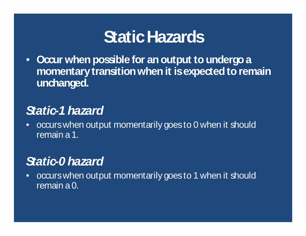
Static Hazards• Occur when possible for an output to undergo a
momentary transition when it is expected to remain unchanged.
Static-1 hazard• occurs when output momentarily goes to 0 when it should
remain a 1.
Static-0 hazard• occurs when output momentarily goes to 1 when it should
remain a 0.

Race conditions
• Static hazards or dynamic hazards are combinational circuit hazards.– generally are only significant in synchronous sequential
circuits.
• In contrast, a race hazard is found only in asynchronous sequential circuits – caused by the interaction between a primary and a secondary signal
change.
• Can be eliminated by introducing delays in the circuit.

Stability Considerations
Due to feedback connections
• Care must be taken to ensure that the circuit does not become unstable.
• An unstable condition will cause the circuit to oscillate between unstable states.
• The transition table method of analysis can be useful in detecting the occurrence of instability

Stability Considerations
Consider following example
The transition table
x2
yYx1
2212121 xyxxxyxxyxY
0
00x1x2
0
10
1
0
0
0 1
1
01 11 10y

Stability Considerations
• Those values of Y that are equal to y are circled and represent stable states
with input x1x2 fixed at 11 the values of Y and y are never the same.
if y=0 then Y=1 transition to 2nd row of table with y=1 and Y=0. This then causes a transition back to the 1st row, with the result that the
state variable alternates between 0 and 1 indefinitely as long as the input is 11.
0
00x1x2
0
10
1
0
0
0 1
1
01 11 10y
Stability Considerations
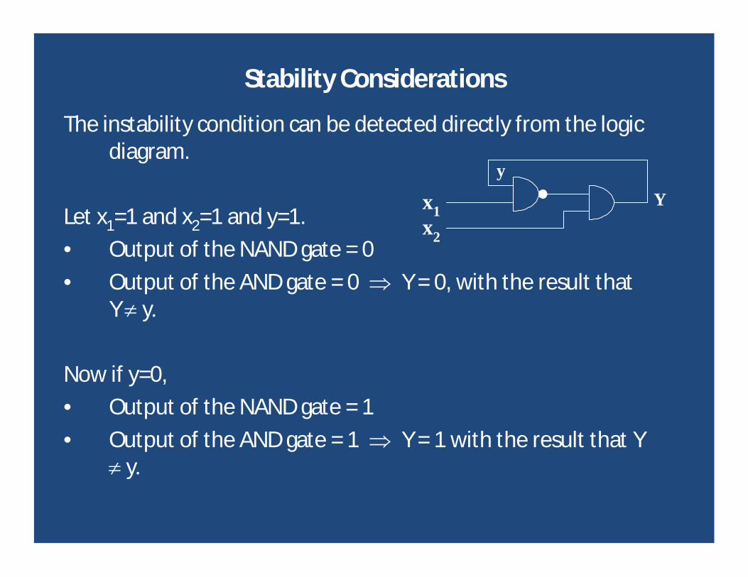
The instability condition can be detected directly from the logic diagram.
Let x1=1 and x2=1 and y=1.
• Output of the NAND gate = 0
• Output of the AND gate = 0 Y = 0, with the result that Y y.
Now if y=0,
• Output of the NAND gate = 1
• Output of the AND gate = 1 Y = 1 with the result that Y y.
x2
yYx1

Stability Considerations
• If it is assumed that each gate has a propagation delay of 5 nseconds (including tracks on PCB),
Find that Y = 0 for 10 nseconds Also Y = 1 for the next 10 nseconds.
• This will result in a square wave waveform with a period of 20 nseconds.
Frequency of oscillation is 50MHz.
• Unless designing a square wave generator, the instability that may occur in asynchronous sequential circuits is undesirable and must be avoided.
x2
yYx1

Design Example
• Consider a circuit of one input and one output.
• A series of pulses is applied to the input and every alternate pulse is to be passed to the output.
– Note the pulse duration and separation are variable.
input x
output Z1 2 3 4 1 2 3 4 1 2

Moore Model
• A Moore model state diagram for this circuit can be designed– Moore models are often used for asynchronous sequential circuits
because a stable state is clearly identified in the Moore model by a “return” path around the state.
– A transition from a stable state will only occurs when the input changes from the return value
01/0 2/0 3/0 4/1
1 0 0
0
0
1 1
1/0State
Output

Primitive Flow Table
• The next step is to draw the state table giving the information in tabular form. i.e. the primitive flow table
Present State Next State Output Z
1 1 2 0
2 3 2 0
3 3 4 0
4 1 4 1
01/0 2/0 3/0 4/1
1 0 0
0
0
1 1

Flow Table
• Stable states are again indicated by circles around the stable state numbers in the Next State columns
– 1, 2, 3, 4– Circled state will be the same as the number
in the present state column.
• Output tries to attain to the stable state
• Primitive flow table should then be minimised where possible
– no minimisation in this example.
• Secondary variables are now assigned.
Present State
Next
State
Output Z
1 1 2 0
2 3 2 0
3 3 4 0
4 1 4 1

Assigning Secondary Variables
• Care must be taken not to make an assignment, which results in more than one variable change between states.
• Use a transition table/map which has states chosen for each square on the map
• Transitions from one state to another are marked on the map and if any show a diagonal path across two variable changes, a new assignment must be made.
1
y2y1
0 1
0 1 2
34

Assigning Secondary Variables
The assigned flow table can then be written by inspection.
Swapping state assignments for 1 and 2 would result in an unsatisfactory map.
Present Statey1y2
Next0
State Y1Y21
Output Z
1 00 01 0
2 11 01 0
3 11 10 0
4 00 10 1

Circuit Implementation
• Two principal implementations possible
1. Purely combinational logic gates2. Combinational logic gates with asynchronous RS flip flops.
• Historically, asynchronous sequential circuits were known and used before synchronous sequential circuits were developed
– First practical digital systems were constructed with delays which were more adaptable to asynchronous type operations
– For this reason, the traditional method of asynchronous sequential circuit configuration has been with components that are connected to form one or more feedback loops.

Circuit Implementation
• As electronic digital circuits were developed, it was realised that the flip-flop could be used as the memory element.
– Use of RS-latch in asynchronous sequential circuits produces a more orderly pattern, which may result in a reduction of the circuit complexity.
– An added advantage is that the circuit resembles the synchronous circuit in having distinct memory elements that store and specify the internal states.
• The RS-flip flip design approach assigns one flip-flop for each secondary variable.
– The inputs to these flip-flops are determined by the required change of y to Y.

Circuit Implementation with RS Flipflops
• Using the following table
Obtain one function for each flip-flop input as shown below.
RequiredChange Qt
OutputTo Qt+1
Flip-flopS
InputsR
0 0 0 X
0 1 1 0
1 0 0 1
1 1 X 0

Circuit Implementation
000
11
01
10
0 1y1y2
x
0
01
XX
X0
S2
xyS 12
X00
11
01
10
0 1y1y2
x
X
X0
00
01
R2
xyR 12
100
11
01
10
0 1y1y2
x
0
XX
0X
00
S1
000
11
01
10
0 1y1y2
x
X
00
10
XX
R1
xyS 21 xyR 21

Circuit Implementation
The final circuit is
1y2y Z
1yx
x
x
1y
2y
2yx
11 yY
11 yY
22 yY
22 yY2S
2R
1S
1R
xx
x
Circuit Implementation
• A particular advantage of the RS flip-flop method is that it is not necessary to correct for static hazards
– As all the prime implicants are present in both the set and reset functions, which will be the case in all problems.
– Hence the RS flip-flop method often requires less components.

Circuit Implementation
• In the RS flip-flop method, both true and complemented y outputs are available for feedback to the flip-flop inputs.
– If the set and reset function of the flip-flop includes true and complemented variables, it is possible that both Set and Reset are a 1 together during a transition, causing both the y and outputs to be 0.
• This might cause a critical race hazard, though this is unlikely with two-level circuits. The inverse y and output can be generates using a separate gate is necessary.

Summary
• Asynchronous circuits very useful for many applications
– Care must be taken in their design.