Embed Size (px)
Citation preview

Revista Ingenierías Universidad de Medellín
Revista Ingenierías Universidad de Medellín, vol. 11, No. 20 pp. 227 - 238 - ISSN 1692 - 3324 - enero - junio de 2012/258 p. Medellín, Colombia
ASYMMETRICAL CAPACITOR: EXPERIMENTS AND MODELING
Josué Rincón*
Iván Amaya**
Rodrigo Correa***
Recibido: 11/10/2010Aceptado: 25/05/2012
ABSTRACTThis research article describes experiments using several Asymmetrical Ca-
pacitors prototypes (AsC) with the objective to reproduce this unusual physical phenomenon, as well as to show its exceptional characteristics. Some results are published for the first time. The operating voltage was increased up to 31kV using a DC generator. The AsC levitated in every experiment, simultaneously generating a gas current from the lowest superficial area electrode. Although this phenomenon has been known for over one century, its scientific basis remains unknown and there isn’t a model that properly explains its behavior under different conditions. It was proved that it works as a conventional electrostatic separator because it eliminated solid particles from a gas sample either confined in a container or flowing, with the advantage of low energy requirements. In the same way, at operating conditions, it produces ozone in a controlled way, as in the corona effect.
Key words: lifter, capacitors, air ionization, propulsion.
* Electronics Engineer. Universidad Industrial de Santander. E-mail: [email protected].** Mechatronics Engineer. Ph.D.(c) on Electronics Engineering. Universidad Industrial de Santander. E-mail: [email protected].*** Ph.D. Universidad Industrial de Santander, Cra. 27 Cll. 9, (057-7) 6344000. Professor. E-mail: [email protected].

228 Josué Rincón - Iván Amaya - Rodrigo Correa
Universidad de Medellín
CONDENSADOR ASIMÉTRICO: EXPERIMENTOS Y MODELADO
RESUMENEl presente artículo de investigación describe experimentos realizados utilizando
prototipos de condensadores asimétricos (CAs), con el fin de reproducir este inusual fenómeno físico y mostrar algunas de sus excepcionales características. Algunos resul-tados aparecen por primera vez en la literatura. Se utilizó un generador de 31kV CC y se observó que en todos los casos el CAs levitó, generándose simultáneamente una corriente de gases en el electrodo de menor área superficial. Aunque este fenómeno se conoce hace más de un siglo, su fundamento científico es aún desconocido y no hay un modelo que explique satisfactoriamente su comportamiento a diferentes condiciones experimentales. Se comprobó que opera en forma equivalente a un sepa-rador electrostático convencional eliminando partículas sólidas de un gas encerrado en un recipiente o en flujo, con la ventaja de un bajo consumo de energía eléctrica. Igualmente, a las condiciones de operación, produce ozono de forma controlada, similar al efecto corona.
Palabras clave: levitador, condensador, ionización de aire, propulsión.

229Asymmetrical capacitor: experiments and modeling
Revista Ingenierías Universidad de Medellín, vol. 11, No. 20 pp. 227 - 238 - ISSN 1692 - 3324 - enero - junio de 2012/258 p. Medellín, Colombia
INTRODUCTIONIn electronics, a conventional capacitor is a
passive component that can store electric energy, consisting of a pair of conductors separated a distance that allows the presence of a dielectric between them. It is well known how to ideally determine the amount of energy stored in the elec-tric field of a dielectric, mostly neglecting border effects. Similarly, the mechanical force between plates can be calculated assuming identical cross sections. Generally, this effect depends on geome-trical factors, increasing with the cross section of the conductor (plates) and inverse to the distance between them (while using smooth parallel-plates). However, this relative simplicity becomes a problem of unexpected characteristics when the size of one of the plates’ cross section becomes considerably smaller than the other one, with sharp corners and borders, and applying a potential difference in the order of kilovolts. The resulting effect is so complex that, there currently isn’t either a physical or mathematical basis that successfu-lly describes not only its dynamics, but also its behavior.
These conditions generate a thrust that levi-tates the assymetrical condenser (AsC) at variable altitudes and lead to leak currents. This physical phenomenon was first reported in 1920, but it wasn’t until the 70s that some applications were researched [1]. In this paper, basic experiments are presented to show some characteristics of the AsC. Likewise, we discuss some mathematical models intended to reflect experimental data. Among several reported preliminary studies, it stands out the one carried out by T. Brown and profes-sor P. Biefeld, from where the so-called Biefeld-Brown phenomenon (1920) arises, as shown in the literature [1-7].
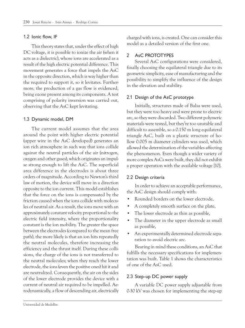
1 PHENOMENON DESCRIPTIONThe levitation phenomenon caused in this
capacitor is observed when energizing a pair of electrodes with a voltage in the order of thousands
of volts, without electric arc. Both surfaces must be uniform to avoid effect diminishing. When ope-rating with voltages between 24 and 31 kV there’s a noise similar to the one present in the corona discharge in a conductor [8, 9]; similarly, there’s also a constant gas flow approximately 3 to 5 °C under room temperature. When observed in the darkness, blue and violet points can be appreciated in both electrodes, accentuated especially in areas with sharp tips or irregular coating sections of the positive one. This observation hasn’t been reported before in the literature. This effect was reproduced with an electrical tension higher than 23kV DC, using a copper thread with or without varnish coating, energized with an aluminum electrode as a reference, to lift the structure observed in Figure 1.
Figure 1. Model of the AsC used in the experiments.
Source: Authors
1.1 Phenomenological models
Documentation revision allowed identification of two main trends [2-4, 6, 10]. Particularly, Bahder et al. [6] carried out an interesting proposal for the modeling of this phenomenon, making an ap-proach from thermodynamics when the capacitor is immersed in a non-lineal dielectric. Since this model is still in development, experimental data will have to validate it.
230 Josué Rincón - Iván Amaya - Rodrigo Correa
Universidad de Medellín
1.2 Ionic flow, IF
This theory states that, under the effect of high DC voltage, it is possible to ionize the air (when it acts as a dielectric), whose ions are accelerated as a result of the high electric potential difference. This movement generates a force that impels the AsC in the opposite direction, which is way higher than the required to support it, so it levitates. Further-more, the production of a gas flow is evidenced, being ozone present among its components. A test comprising of polarity inversion was carried out, observing that the AsC kept levitating.
1.3 Dynamic model, DM
The current model assumes that the area around the point with higher electric potential (upper wire in the AsC developed) generates an ion rich atmosphere in such way that ions collide against the neutral particles of the air (nitrogen, oxygen and other gases), which originates an impul-se strong enough to lift the AsC. The superficial area difference in the electrodes is about three orders of magnitude. According to Newton’s third law of motion, the device will move in a direction opposite to the ion current. This model establishes that the force on the ions is compensated by the friction caused when the ions collide with molecu-les of neutral air. As a result, the ions move with an approximately constant velocity proportional to the electric field intensity, where the proportionality constant is the ion mobility. The greater the space between the electrodes (compared to the mean free path), the more likely is that an ion hits repeatedly the neutral molecules, therefore increasing the efficiency and the thrust itself. During these colli-sions, the charge of the ions is not transferred to the neutral molecules; when they reach the lower electrode, the ions (even the positive ones) hit it and are neutralized. Consequently, the air on the sides of the lower electrode provides the device with a current of neutral air required to be impelled. Ae-rodynamically, a flow of descending air, electrically
charged with ions, is created. One can consider this model as a detailed version of the first one.
2 AsC PROTOTYPESSeveral AsC configurations were considered,
finally choosing the equilateral triangle due to its geometric simplicity, ease of manufacturing and the possibility to simplify the influence of the design in the elevation and stability.
2.1 Design of the AsC prototype
Initially, structures made of Balsa were used, but they were too heavy and were prone to electric arc, so they were discarded. Two different polymeric materials were tested, but they’re too unstable and difficult to assemble, so a 0.150 m long equilateral triangle AsC, built on a plastic structure of ho-llow 0.005 m diameter cylinders was used, which allowed the determination of the variables affecting the phenomenon. Even though a wider variety of more complex AsCs were built, they did not exhibit a proper operation with the available voltage [10].
2.2 Design criteria
In order to achieve an acceptable performance, the AsC design should comply with:
• Roundedbordersonthelowerelectrode,
• Acompletelysmoothsurfaceontheplate,
• Thelowerelectrodeasthinaspossible,
• Thediameterintheupperelectrodeassmallas possible,
• Anexperimentallydeterminedelectrodesepa-ration to avoid electric arc.
Bearing in mind these conditions, an AsC that fulfills the necessary specifications for implemen-tation was built. Table 1 shows the characteristics of one of the AsC used.
2.3 Step-up DC power supply
A variable DC power supply adjustable from 0-30 kV was chosen for implementing the step-up

231Asymmetrical capacitor: experiments and modeling
Revista Ingenierías Universidad de Medellín, vol. 11, No. 20 pp. 227 - 238 - ISSN 1692 - 3324 - enero - junio de 2012/258 p. Medellín, Colombia
DC voltage source, since it offers a proper operation range. A flyback converter was used given its ease of configuration and operation. The variation in the output voltage can be controlled by a frequency or voltage control on the flyback converter’s input signal. Ventilation and a dissipative system that guarantees the operability of the devices in an acceptable margin of temperature for as long as possible were implemented. The dissipation of the generated heat was a problem solved in order to prolong the useful life of the source.
2.4 Description of the circuit
The circuit consists of a step-down transformer that allows a maximum output of 80V DC after rectification; this output is sent to a BJT transistor that regulates this signal from 0V to its maximum value and reduces the flyback converter’s input voltage. This output is also used for obtaining a 12V signal using a voltage regulator; an oscillator provides frequency switching for an output voltage sweep. The variation in the output is carried out varying the flyback’s converter’s input voltage or os-cillating frequency. The implemented power supply provides two outputs: one of up to 30 kV DC, and the other one varies in the range of 0-80 V DC [10]. Regarding the design of the current source, the greatest difficulty was related to the transistors given their narrow operating temperature range. The frequency of the oscillator, implemented
using a LM555, can be varied between 15 kHz and 35 kHz and it is used for controlling the flyback converter’s frequency and thus the output voltage as well. In order to improve the voltage sweep, 5-10 turn lineal potentiometers were used [10].
3 TESTS AND RESULTSDuring the implementation and testing stage
it was considered that the distance between the upper copper wire and the aluminum base should be sufficiently small to allow ionization of the air, but not so small as to produce an electric arc. The AsCs were operated with voltage between 21 kV and 28 kV, and all the measurements reported in this article were made with relative humidity bet-ween 65% and 75% and room temperature in the range of 23 to 26 ºC. A series of tests performed to observe the phenomenon having some changes in the AsC’s structure are now described [10].
Test 1: Helix
This test is intended to observe the existence of ionic currents, for which a power supply of 8 kV was used. In this case, the prototype was a helix elaborated in aluminum paper that rotates because of a flow of air generated in the borders of the electrode when they are connected. It can be also observed an electric arc when bringing the electrode close to the system reference (from 0.01 to 0.007 m), see Figure. 2.
Figure 2 Prototype Helix.
Source: Authors
Table. 1 Characteristics of an AsC used for testing
Characteristic Value
Total weight 0.0035 kg
Shape: equilateral triangle
Width: 0.04m Length: 0.15m
Plastic tubes (for support)
Diameter: 0.005m Length: 0.095m
Upper electrode (copper wire)
Diameter: 0.00008m
Source: Authors

232 Josué Rincón - Iván Amaya - Rodrigo Correa
Universidad de Medellín
In Figure 2, it can be observed the helix after applying the voltage. This test shows that the force that impels the helix is oriented in the electrode’s sharper borders, which correspond to the bor-der of the aluminum sheet. Moreover, a suitable configuration leads the electrode to spin around on its axis. Similarly, if the reference electrode is placed in the darkness, 0.06 m from the other one, a point of light can be observed at the end of both electrodes, which indicates that even though a flow between them is not perceived, the field with more potential finds the closest point with the highest voltage difference in order to balance the charges.
Test 2: Pictures in the darkness
During this test the equilateral triangle-shaped AsC with 0.15 m side was used. Figure 3 shows the gleam of the ions that moves the copper wire in the upper side of the AsC toward the aluminum plate; the vanishing points describe the same path as the DM predicts. It is observed that the ionization of the air is not performed in a uniform way. Howe-ver, the line of partially equidistant points allows generation of a uniform and balanced flow that elevates the AsC. The levitation of the AsC is not carried out gradually, but it is reached at a certain point where the air flow is sufficiently strong to lift its weight.
Figure 3. Prototype levitating, power supply 21 kV.
Source: Authors
Likewise, the levitation is not controlled, since a continuous variation in the descending currents varies the ionization of the surrounding air and thus changes the device’s position. Stability can be improved with the increase of the power supply and an aerodynamic geometric design. Figure 4 shows the brightest white point, which corresponds to the copper wire where the voltage is maximal and which exhibits higher ionization. This effect is observed only when the copper wire has varnish coating. If bare copper wire is used, a uniform luminous border is observed along the conductor, but with less intensity. The arrows show the curves of ionic flow leaving the upper electrode (copper wire) toward the lower electrode, an aluminum sheet. The flow is not direct from an electrode to the other one.
Figure 4 Points of higher ionization on the copper electrode.
Source: Authors
On the other hand, a thermogram of the AsC levitating shows that the temperature increases slightly in the upper electrode, while the flow temperature of generated gas is slightly under room temperature (26 °C), Figure 5.

233Asymmetrical capacitor: experiments and modeling
Revista Ingenierías Universidad de Medellín, vol. 11, No. 20 pp. 227 - 238 - ISSN 1692 - 3324 - enero - junio de 2012/258 p. Medellín, Colombia
Figure 5. Thermogram of the capacitors levitating.
Source: Authors
Test 3: Styrofoam spheres
In order to observe the flow direction of the gas emitted by the AsC, Styrofoam spheres were thrown to the capacitor while it was levitating. Even though the previous test had shown that the force and direction of the flow between the electrodes is outwards, ionization generated by the field make the sphere adhere to the lower electrode and after some minutes the AsC falls due to excess of weight. After falling and once the surface of the electrode is saturated with these spheres, the flow
generated between the electrodes begins repelling the Styrofoam spheres that are thrown like in a fountain (Figure 6), having the strongest repulsion at the triangle’s centroid. The spheres fall around the aluminum electrode and then they are expelled very strongly.
Test 4: SmokeThis test is intended to determine the orienta-
tion of the gas flow. Initially, smoke was injected on the sides of the triangle to observe its direction, but
Figure 6. Styrofoam spheres thrown to the AsC, power supply 25kV.
Source: Authors

234 Josué Rincón - Iván Amaya - Rodrigo Correa
Universidad de Medellín
by doing so the smoke vanished. Therefore the AsC was put into a capsule which was filled with smoke.
Using this configuration, it was observed that the system attracts, very quickly, all the particles to the lower electrode (aluminum sheet), leaving the capsule completely clear and with an evident smell of ozone in the air (Figure 7). After the experiment, a deposit of yellow oil was left on the aluminum electrode. This result can be explained considering that the AsC behaves as a conventional electrostatic separator catching and depositing particles on the negative electrode, i.e. electric charge of the parti-cles must be positive. Although it is also possible that vapor from organic substances in the smoke underwent phase transitions due to the temperatu-re of the aluminum electrode, thermogram images discarded it.
Test 5: Variation of the copper wire diameter (upper electrode)
To observe the effect of varying the diameter of the copper wire, some rectangles were elaborated with calibers varying between 18 and 40 (0.00008 and 0.00102 m); they were supplied with a constant voltage of 24kV. The enlargement of the diameter evidenced a noise and gas increase. For the AsC, it was observed that increasing the caliber makes
the structure heavier. However, the net force was not compensated, since the AsC did not levitate for the applied voltage. In tests carried out in the darkness it was observed that the level of brightness does not vary significantly. Likewise, a bare copper wire with varnish coating was used; as before, a significant decrease was observed in the generated noise, and, again, more uniformity is achieved when removing the coating. Five wire diameters were chosen for performing the tests: calibers 18, 23, 24, 26 and 40. The test with copper electrode, with and without coating, used a triangular AsC and the same voltage. The AsC with bare wire exhibited a light decrease in its elevation force compared to the one with coating.
Test 6: Camera with carbon dioxide
This test was carried out using non ionizable material and operating conditions of 25 kV and atmospheric pressure. The AsC was located into a camera with CO2. The results show that in pre-sence of this compound there is neither levitation nor generation of electric arc; these results provide, at least for these particular operating conditions, experimental support to the outlined hypothesis about the requirement of generation of ionic cu-rrents for the elevation of the AsC.
Figure 7. System before and after supplying 25kV to the AsC. The AsC is stuck on the surface
Source: Authors

235Asymmetrical capacitor: experiments and modeling
Revista Ingenierías Universidad de Medellín, vol. 11, No. 20 pp. 227 - 238 - ISSN 1692 - 3324 - enero - junio de 2012/258 p. Medellín, Colombia
Test 7: Vacuum test
This test is intended to determine if in a moderate vacuum environment, the phenomenon is observed. For this, a hermetically sealed glass recipient and a conventional vacuum pump were used. The AsC was inserted into the recipient and vacuum was generated. Under these conditions, the AsC does not levitate and the electric arc genera-tion between the electrodes increases. The vacuum tests carried out by other authors produce the same results. This aspect is very important because it allows elucidating which of the proposed models describes the phenomenon in an appropriate man-ner. However, these results can be interpreted as no (or insufficient) thrust generation.
Test 8: Variation in the dimension of the aluminum electrode
Some variations were carried out in the dimen-sions of the aluminum electrode in order to observe possible effects. The conditions for this test were 26 ºC and 64% humidity. Table 2 shows a series of voltage and current measurements for each size of the electrode. The width of the aluminum elec-trode was varied between 0.01 and 0.04 m. It was observed that the size of the sheet influences the stability and the flight of the AsC; so that in order to have an acceptable behavior with the triangle of 0.15 m side, a sheet 0.04 m width was required as well as a distance between the copper wire and the aluminum of 0.03 m. However, it was observed that all the AsCs with the selected aluminum widths levitated without difficulty [10]. In all the perfor-med tests the characteristic smell of the ozone was perceived, and it is produced in similar way by using high voltage. Ozone is produced usually by opera-tion of laser printers, photocopiers, piston engines, or any other equipment that bases its operation in high voltage discharges in presence of air (corona effect). This ozone is considered a potential source of contamination at low altitudes and it exists in relatively high concentrations in cities with high
vehicle flow; nevertheless, this ozone is unstable in presence of ultraviolet rays and under other experimental conditions is relatively easy to obtain. Given its physical and chemical properties, it is used for eliminating bacteria in water treatment and commercial equipments to purify water using ozone are well-known.
Table. 2 Input voltage and current as a function of width of lower electrode
Width [m] V DC [kV] I [mA]
0.01 25.5 0.057
0.02 26.9 0.059
0.03 27.1 0.062
Source: Authors
Average power consumption
During the tests, the average power consump-tion of the AsC was 45 W for a humidity level of 68% and a temperature of 24.6 °C, respectively.
4 CONSIDERATIONS FOR AN EXPLANATORY MATHEMATICAL MODELThe proposed model is based on the analysis
and observation of the experimental results. First, it was observed that when applying a high voltage, the AsC levitates and because of limitations of longitude on the electrodes, it was necessary to limit the altitude at a fixed distance tying it to the surface. Summarizing, a first approach shows that the generated force is greater than the weight of the AsC and it is very close to the tension on the strings that retain it. Secondly, in the pictures that had not been reported in the literature, a gas flow is clearly observed from some points in the smaller area electrode, independent of its polarity (which was commuted many times). Third, the appearance of ozone can indicate that there was an ionization

236 Josué Rincón - Iván Amaya - Rodrigo Correa
Universidad de Medellín
of the air surrounding the electrode; it is the well-known corona effect due to a high potential difference, independent of the current. All this supports the conclusion that it is a phenomenon originated by electrostatic forces in presence of an ionic current, as several researchers have suggested in recent years, although they assumed the presence of N2 ions and assume that all the ions move directly from one electrode to the other one, but with no experimental support [5, 6]. In this work, it was demonstrated, supported by pictures (Figure 3 and 4), the direction of a current and with an additional experiments, we verified that if this flow is interrupted between electrodes using a surface, the system is destabilized and it carries out abrupt movements showing a reaction to this interruption of the ionic f low [10]. Also, Bahder et al. [6] suggest that the path of this ionic current is direct, but as it is shown in Figure 3 and 4, it creates a flow curvature, indicating axial components of both, current and thrust. Unfortunately, after performing several very similar experiments to those carried out in this work, Canning et al. [3, 5] do not mention the generation of ozone, even though its presence becomes evident given its organoleptic characteristics, and moreover its presence and concentration can be corroborated using a commercial sensor for ozone [A21ZX of Applied Ozone Systems]. From these general experimental considerations, it can be assumed that the repulsion force among the charges in the leak current is represented as F=qE, where q is the total charge and E is the electric field between the electrodes. If this field is expressed as a function of the voltage (V) between the plates and the distance between them (d) and if the definition of electric current (I) as the quantity of charge (q) over time (t) is used, we obtain F = V I (t/d), [N]. Estimating, from basic laws of physics, the distance between collisions (dcolli), it can be obtained that dcolli = (1/2)a(tcolli)2 where a is the acceleration and tcolli is the time required to cover this distance. The corresponding force is
F=Ve/d=ma, where e is the charge of an ion (1.6x10⁻¹⁹ C) and m its mass (4.7x10⁻²⁶kg), assuming positively charged nitrogen ions. It would be necessary to determine the real composition of the “plasma” generated around the electrodes, but, as an initial calculation, it is a good approach. Thus we have dcolli = (1/2dm) Ve (tcolli)2. Now, if it is accepted that there is proportionality between the time of ion collisions and the time required to cover the distance until reaching the other electrode, and that in normal conditions of pressure there are 1010 collisions per second on average, it can be obtained that the repulsion force F, which is supposed to be at least one of the responsible for the thrust that makes the AsC levitate, has a magnitude in the order of F = (2x10¹⁰ m/e) I d, [N]. The magnitude of this force for three of the AsCs with different weight, listed in Table 2, is observed in Table 3.
The last column indicates the mass of the AsC that could be lifted if the required force, calculated as shown, is generated. This mass is considerably greater than the one of the AsC used in the experiments, and therefore the thrust is much greater than the required to lift the current AsC prototypes, and indeed they levitated easily. Although the tests performed are neither enough nor conclusive, they constitute a macroscopic expla-nation consistent not only with the experimental results we obtained, but also with those reported by other authors [2-6, 10].
Table. 3 Estimation of the force generated in some of the AsCs used in the experiments
Width [m] I [mA] Mass [g] F/grav, [g]
0.01 0.057 4.567 102.513
0.02 0.059 4.704 106.110
0.03 0.062 4.834 111.500
Source: Authors

237Asymmetrical capacitor: experiments and modeling
Revista Ingenierías Universidad de Medellín, vol. 11, No. 20 pp. 227 - 238 - ISSN 1692 - 3324 - enero - junio de 2012/258 p. Medellín, Colombia
5 CONCLUSIONSA series of experiments carefully performed
was presented, some of them reported for the first time in the literature. This interesting phenome-non has a high potential from an academic as well as a technological perspective. However, despite being known for over a century, there is still a lack of knowledge about its physical basis and mathe-matical model, and therefore further research is recommended.
REFERENCES
[1] T. Brown, US patent 3187206, Electrokinetic Appara-tus, 1965.
[2] F. Canning, et al., Asymmetrical Capacitors for Pro-pulsion, NASA TM CR-2004-213312, 2004.
[3] F. Canning, et al., “Asymmetrical Capacitors for Pro-pulsion” Proceedings of the 53rd JANNAF Propulsion, 1-16, 2005.
[4] J. Campbell, US patent 6317310 Apparatus and method for generating thrust using a two dimensional asym-metrical capacitor module, 2002.
[5] F. Canning, “Experimental findings of lifters, asym-metrical capacitor thrusters, and similar electrogravitic devices”. AIAA 2006-4910, Sacramento California, USA, 5607-5611, 2006.
[6] T. Bahder, and C. Fazi, “Force on an Asymmetric Capacitor”, Army Research Laboratory, ARL-TR-3005, June, 1-31, 2003.
[7] De Seversky, A. US patent 3130945, Ionocraft, 1964.[8] J. Mojica, “Estudio Teórico práctico del efecto coro-
na”. [Undergraduate thesis], Universidad Industrial de Santander, 1973.
[9] R. Vila, “Medidas de pérdidas corona y nivel de radio interferencia en líneas cortas enmalladas” [Master thesis], Universidad Industrial de Santander, 2005.
[10] L. Martinez, and J. Rincon, “Prototipo de un sistema de ionización” [Undergraduate thesis], Universidad Industrial de Santander, 2008.