Embed Size (px)
Citation preview

Assessment of Deep-Well Injection of Liquid Wastes from Hydraulic Fracturing
Ronald T. Green, Ph.D., P.G. and F. Paul Bertetti, P.G. Geosciences and Engineering Division
Southwest Research Institute®
Eagle Ford Center for Research, Education, and Outreach
November 18, 2014

Issues for Hydraulic Fracturing Operations
EPA, 2011

Narrowly Framed Discussion of Hydraulic Fracturing
EPA, 2011

Full Life Cycle of Fracking is Important
EPA, 2011

How Much Water Does Fracking Use? (Per Well)
• Conventional oil/gas well requires 100,000 gallons
• To frack one stage of a horizontal well requires 300,000 gallons
• Horizontal well could have 15-25 stages
• Total water required to frack a horizontal well: >5,000,000 gals
• Rate: 4-8 stages/day requires 1,200,000-2,400,000 gallons per day

How Much Water Does Fracking Use? (Total Water Consumption)
• About 1/3% of all freshwater used in U.S.
• About 1% of all freshwater used in Texas
• About 6% of all freshwater used in southern Texas
• About 1/3 to 1/2 of all recharge in SW segment of Eagle Ford play
• How much water is a local issue, regional averages don’t matter when your well goes dry

Handling and Disposal of Waste Fluids Poses Greatest Risks
EPA, 2011

Fracking Flowback and Produced Water What Happens to It?
• Recycle and reuse of fracking flowback and produced water is
an area of active development, many promising technologies.
Limitation is capacity.
• Disposal of waste fluids poses greater risks: pits, tanks, pipes,
trucking, injection, treatment, etc. These risks have not been
adequately assessed.

Deep-Well Disposal of Waste Fluids
• Energy Policy Act of 2005 specifically exempts fracking fluids from Safe Water Drinking Act Regulations (aka Haliburton Loophole) SEC. 322. HYDRAULIC FRACTURING is amended to read as follows:
(1) UNDERGROUND INJECTION
(A) means the subsurface emplacement of fluids by well injection; and
(B) EXCLUDES
(ii) the underground injection of fluids or propping agents (other than
diesel fuels) pursuant to hydraulic fracturing operations related to oil,
gas, or geothermal production activities.
• Class II wells – Salt Water Disposal (SWD) wells

Injection Well Classification: EPA
• Class I hazardous wastes, industrial non-hazardous liquids, or municipal wastewater. 680 wells
• Class II brines and other fluids associated with oil and gas production, and hydrocarbons for storage. 172,068 wells
• Class III solution mining of minerals. 22,131 wells
• Class IV hazardous or radioactive wastes into or above USDWs. 33 sites
• Class V All injection wells not included in Classes I-IV, non-hazardous fluids into or above USDWs. 400,000 to 650,000 wells
• Class VI Geologic Sequestration of CO2 6-10 commercial wells expected to come online by 2016.

What are the Actual Risks Associated with Hydraulic Fracturing?
Migration of frack fluids through 1,000s ft of rock along fault or
through confining layer – not likely unless vertical separation is
minimal
Disposal of waste fluids poses greater risks: pits, tanks, pipes,
trucking, injection, treatment, etc. These risks have not been
adequately assessed.

Threat from Abandoned Wells — Breakout
Unknown threat from hydraulic fracturing by deep-well injection of waste fluids

What’s the Risk of Breakout Associated with Abandoned Wells?
• Oil drilling began in earnest in the early 1900s – Records of wells, especially older wells, are often incomplete or absent
– Well construction standards weren’t what they are today
– Structural integrity of older abandoned wells may be compromised
– How many? Estimates vary from less than 10,000 to over 110,000 (orphan and inactive) wells in Texas
• Disposal of hydraulic fracturing waste fluids by >12,000 disposal wells in Texas – RRC requires notification of all occurrences of breakout, but doesn’t
maintain a single database
– RRC retains records on breakout for only two years
– There are documented cases where breakout resulted in disposal fluid discharge above ground
– In absence of a centralized database, risk is unknown, but possible

Well Casing Corrosion and Cement Failure
Holes from Corrosion
Cement Failure • Formation damage during drilling (caving) • Casing centralization (incomplete cementing) • Non-adequate drilling mud removal • Incomplete cement placements (pockets) • Inadequate cement-formation/cement casing bond • Cement shrinkage • Contamination of cement by mud or formation fluid • Filtration of the cement slurry • Fracture formation with cement
Casing Failure • Sweet corrosion (CO2
corrosion) • Sour corrosion (H2S corrosion) • Oxygen corrosion • Galvanic corrosion • Crevice corrosion • Erosion corrosion • Microbiologically induced
corrosion

Geriatric Wells and Well Fields
Waste fluids can be flowback, produced
water, or oil/gas products.
This of particular concern when:
• Field is old
• H2S is present
• Field is still active, continued water flood
• Close to disposal wells

At What Distance are Abandoned Wells a Threat?
Disposal Well Permit Regulation (Texas)
Predicated on Isotropic Media
… the applicant shall review … wells that penetrate the proposed disposal zone within a 1/4 mile radius of the proposed disposal well to determine if all abandoned wells have been plugged in a manner that will prevent the movement of fluids from the disposal zone into freshwater strata.
This regulation assumes radial flow and does not account for natural heterogeneity present in geologic media.

How are injected fluids assumed to flow?

Homogeneous and Isotropic Injection Plume Geometry and Size
Plume radius for 50,000 barrels of injection for
formation thicknesses of 300 and 600 ft and
effective porosities of 5%, under homogeneous
and isotropic conditions.
Uniform growth of injection plume under
homogeneous and isotropic conditions.
0
1,000
2,000
3,000
4,000
5,000
6,000
7,000
0 5 10 15 20
Rad
ius
of
Inje
cte
d P
lum
e (
ft)
Years After Start of Injection
300’ injected horizon
600’ injected horizon
¼ mile radius

How do injected fluids actually flow?

Geologic Structure Induced Preferential Flow
Injected fluids tend to follow geologic structure and
in situ stress instead of an isotropic sphere or cylinder
An injection well has greater influence
in the direction of maximum horizontal stress and major faults and fractures

Damage due to Tensile Failure Damage due to Compressive/Shear failure
Analyses Provide Indication of How Injected Fluids Actually Flow
Effect of Inclined Layering at depth of 3 km (~9,800 ft)
Mechanical stratigraphic layering strongly controls damage/strain patterns
Overall damage patterns suggest substantial fracture connectivity across model domain

Examples of Breakout from Injection Wells

Example 1 Proposed Disposal Well in Oil/Gas Formation
With Abandoned Wells

Area of Interest
Example Disposal Well Complexities

Example of Disposal Well Complexities Proposed Disposal in Former Oil/Gas Field
0 1 2 3 4 0.5
Kilometers
Existing Water Wells
¼-mile radius
Abandoned Wells

Example Disposal Well Complexities
0 1 2 3 4 0.5
Kilometers

Example 2 Proposed Disposal Well in Oil/Gas Formation
With Abandoned Wells

Proposed Disposal Well in Oil/Gas Formation With Abandoned Wells
Location of proposed injection well

Proposed Disposal Well in Oil/Gas Formation With Abandoned Wells
32797 Horizontal Drilled 9/8/1990
Plugged 10/28/1997 Surf. Casing: 0-832 ft
Prod. Casing: 0-5,698 ft Plug depths
1950-2,117 ft 3,148-3,253 ft 5,404-5,500 ft
Open cased hole 5,500 – 6,043 ft
Perf. Zone 5,698-6,300 ft
30487 Drilled 6/4/1976
Plugged 2/20/1986 Surf. Casing: 0-205 ft
Prod. Casing: 0-6,535 ft Plug depths
1450-6,050 ft Open cased hole 6,050 – 6,541 ft
Perf. Zone 6,107-6,445 ft
30488 Drilled unk
Plugged 1/20/1991 Surf. Casing: 0-205 ft
Prod. Casing: 0-6,535 ft Plug depths
3-13 ft 160-350 ft 717-750 ft
1,325-1,198 ft (?) 1,880-2,000 ft 3,050-3,185 ft
Open cased hole 3,185 – 6,516 ft
Perf. Zone 350-351 ft 850-851 ft
1,325-1,326 ft
30665 Drilled 8/26/1976 Plugged 3/25/1983
Surf. Casing: 0-248 ft Prod. Casing: 0-6,584 ft
Plug depths 0-62 ft
148-348 ft 3,150-3,350 ft 5,820-6,020 ft
Open cased hole 6,020 – 6,585 ft
Perf. Zone 6,130-6,150 ft 6,195-6,359 ft
30428 Drilled 4/12/1976 Plugged 3/15/1983
Surf. Casing: 0-222 ft Prod. Casing: 0-6,582 ft
Plug depths 0-10 ft
124-322 ft 3,147-3,345 ft 5,822-6,020 ft
Open cased hole 6,020 – 6,587 ft
Perf. Zone 6,196-6,525 ft
Proposed SWD Injection Horizon
4,500-5,250 ft
½ mile ¼ mile
32682 Pyote SWD Horizontal converted to SWD
Drilled 5/15/1990 Abandoned 1999
Surf. Casing: 0-689 ft Prod. Casing: 0-5,815 ft
Vertical Depth 6,121 ft
Measured Depth 7,709 ft
Base of Usable Fresh Water 3,100
32760 SWD Horizontal converted to SWD
Drilled 7/30/1990 Converted 6/27/1991
Bridge plug set at 5,700 ft Hard bottom at 5,168 ft
Injects into Olmos Original Vertical Depth
6,195 ft Original Measured Depth
8,822 ft
30367 Drilled 2/17/1976 No Record of Plug
Surf. Casing: 0-217 ft Prod. Casing: 0-6,420 ft
SWD Permit 12882 W-14 filed 2/10/09
5,000 bbl/day Amended W-14 filed 6/15/11
20,000 bbl/day denied Injection intervals
4,580-4,700 ft San Miguel 5,100 – 5,160 ft Olmos

Austin Chalk
Anacacho
San Miguel
Olmos
6000 ft
5620 ft
5180 ft
4530 ft
2000 ft
Wilcox
1000 ft
Carrizo
Ground Level
Escondidio
Midway 3100-3,225 ft
Bigford-Queen City
3500 ft
800 ft
(Not to scale)
Fresh Water
Fresh Water
< ¼ mile
Surface Casing
Plug
¼ mile
Originally Constructed as Horizontal Well s
?
?
Proposed Disposal Well in Oil/Gas Formation With Abandoned Wells

Example 3 Existing Disposal Well
Breakout in an Abandoned, Plugged Well

Surface Breakout from Disposal Well
Operating Disposal
Well
Breakout occurred after 2 years of injection in an abandoned
(and plugged) dry-hole oil well located slightly over ¼ mile away
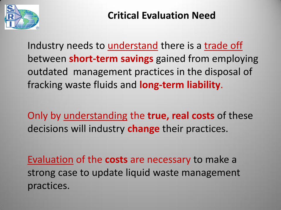
Industry needs to understand there is a trade off between short-term savings gained from employing outdated management practices in the disposal of fracking waste fluids and long-term liability.
Only by understanding the true, real costs of these decisions will industry change their practices.
Evaluation of the costs are necessary to make a strong case to update liquid waste management practices.
Critical Evaluation Need

Actions to Mitigate Risk
There are several actions that can be taken to mitigate the threat of contamination due to “breakout” from a disposal well.
– Accurately examine and document locations and depths of disposal wells and all nearby existing wells.
– Limit or prohibit injection of liquid wastes into formerly productive horizons (not EOR). That’s where the abandoned wells are more likely to be located.
– Increase the ¼-mile radial distance from proposed disposal well over which abandoned wells are searched.
– Develop a single database for all occurrences of “breakout”. Risk from breakout can only be assessed if number of occurrences and their severity are known.

Contact Information
Ronald T. Green, Ph.D., P.G.
Institute Scientist
Geosciences and Engineering Division
Southwest Research Institute
6220 Culebra
San Antonio, Texas 78238
1.210.522.5305 (office)
1.210.522.5184 (fax)
1.210.316.9242 (cell)