Embed Size (px)
Citation preview

Assessing Vibration:a technical guideline
February 2006
Published by: Department of Environment and Conservation 59–61 Goulburn Street Sydney NSW 2000 PO Box A290 Sydney South NSW 1232 phone: (02) 9995 5000 (switchboard) phone: 131 555 (information and publications requests) TTY: (02) 9211 4723 fax: (02) 9995 5999
email: [email protected] website: www.environment.nsw.gov.au
ISBN 1 74137 812 5 DEC 2006/43 February 2006
All text, photos and figures © Department of Environment and Conservation (NSW) 2006, except where noted below.
The cover shows a selection of vibration sources: [clockwise from top left] locomotive (photo: J Goodwin/DEC), hydraulic hammer (courtesy Caterpillar), brake press (courtesy Nepean Engineering, photo: T King/DEC), pile driver (courtesy Macdonald Sheet Piling).
Permission to reproduce extracts from the BS 6472: 1992 in this document granted by BSI. British Standards can be obtained from:
BSI Customer Services 389 Chiswick High Road London UK W4 4AL phone: +44 (0)20 8996 9001 email: [email protected]
Figure B1.5 reproduced by courtesy of Lexis Nexis Australia.
This work is copyright. Apart from any use as permitted under the Copyright Act 1968, no part may be reproduced without prior written permission from DEC.
Every effort has been made to ensure that information in this guide is accurate at the time of printing. DEC cannot accept responsibility for any errors or omissions.
Printed on recycled paper
For technical information about this report, please contact:
Noise Policy Section Policy and Science Division Department of Environment and Conservation (NSW) phone: (02) 9995 5000
Copies of this document and other DEC publications about noise management may be found at: www.environment.nsw.gov.au/noise
Assessing vibration: a technical guideline iii
Executivesummary...................................................................................v
1 Introduction................................................................................................11.1 Overview ................................................................................................................. 1
1.2 Development of the guideline .................................................................................. 1
1.3 Additional features to the approach ............................................................................ 2
1.4 When this guideline should be used and who should use it ................................... 2
2 Vibrationcriteria.......................................................................................32.1 Types of vibration ..................................................................................................... 3
2.1 Application of the criteria ......................................................................................... 3
2.3 Acceptable values for continuous vibration and impulsive vibration (1–80 Hz) ...... 5
2.4 Acceptable values for intermittent vibration ............................................................ 7
2.5 Short-term works ...................................................................................................... 8
3 Mitigation..................................................................................................103.1 Introduction ........................................................................................................... 10
3.2 Controlling vibration at the source.......................................................................... 10
3.3 Controlling the transmission of vibration ............................................................... 12
3.4 Controlling vibration at the receiver ....................................................................... 12
3.5 Managing short-term exceedance of approved vibration values .......................... 12
3.6 Negotiation ............................................................................................................. 13
4 Vibrationmeasurementandprediction................................................144.1 Units of measurement ........................................................................................... 14
4.2 Location and direction of vibration measurement ................................................. 14
4.3 Measurement instrumentation and techniques ..................................................... 14
4.4 Mounting of vibration transducers on buildings ..................................................... 15
4.5 Mounting of vibration transducers on the ground .................................................. 15
4.6 Prediction .............................................................................................................. 16
4.7 Information provided in a vibration assessment report ......................................... 16
Referencesandbibliography..................................................................17
AppendixA:Screeningmethod..............................................................19
AppendixB:BS6472weightings...........................................................20
AppendixC:Vibrationcriteriapresentedindifferentunits.................26
AppendixD:Historyofvibrationcriteria...............................................27
Glossary...................................................................................................29
Contents
Assessing vibration: a technical guideline v
Executive summary
Assessing vibration: a technical guideline is based on guidelines contained in BS 6472–1992, Evaluation of human exposure to vibration in buildings (1–80 Hz). BS 6472 (current and former versions) has guided the Department of Environment and Conservation’s (DEC) evaluation of vibration since the mid-1980s. Thus, this technical guideline does not represent a change in policy approach.
This guideline presents preferred and maximum vibration values for use in assessing human responses to vibration and provides recommendations for measurement and evaluation techniques. It does not address motion sickness, occupational vibration, blasting vibration effects or vibration-induced damage to buildings or structures.
Section 1 provides information on how the guideline was developed, what extra features have been included since the previous guideline (Environmental noise control manual, Chapter 174) and who the guideline is for.
Section 2 provides preferred and maximum values for continuous, impulsive and intermittent vibration. Intermittent vibration is assessed using the vibration dose concept which relates vibration magnitude to exposure time. Relevant multiplying factors are used to derive acceptable magnitudes of vibration on the basis of the receiver type and the nature of the vibration.
The criteria are non-mandatory: they are goals that should be sought to be achieved through the application of all feasible and reasonable mitigation measures. Where all feasible and reasonable measures have been applied and vibration values are still beyond the maximum value, the operator would need to negotiate directly with the affected community.
This guideline presents vibration criteria that use the parameter of acceleration root mean square (rms), measured in metres per second per second (m/s2 ). Criteria are also presented in velocity rms in the appendices.
The assessment of vibration requires the use of an overall frequency-weighted value for each axis (x, y and z directions). This overall value is assessed against the preferred value for the relevant axis. An alternative to using frequency-weighted values is presented as a simplified screening technique in Appendix A.
When predicted or measured vibration values exceed the preferred values, then mitigation measures to meet the preferred values should be considered. The degree of vibration impact quantifies the extent of mitigation required and the mix of vibration control measures to be adopted as a mitigation strategy. Section 3 provides generic information on mitigation measures to reduce vibration effects induced by various activities, but these are not prescribed measures. This section of the guideline is not meant to be exhaustive or to replace the need for specialist advice. Where the preferred values cannot be met, alternative management approaches are presented.
Section 4 provides information on measurement and prediction requirements.
Assessing vibration: a technical guideline 1
1.1 OverviewWhere occupants can detect vibration in buildings, this may potentially impact on their quality of life or working efficiency. In contrast, people tolerate much higher vibration values in vehicles than in buildings.
Sources of vibration covered in this guideline include construction and excavation equipment, rail and road traffic, and industrial machinery. Low-frequency, airborne pressure waves emitted by some heavy vehicles, aircraft and machinery can also cause vibration in buildings. Some vibration sources give rise to audible effects such as structure-borne noise and secondary rattling of building elements or contents.
Individuals can detect building vibration values that are well below those that can cause any risk of damage to the building or its contents. The level of vibration that affects amenity is lower than that associated with building damage.
In keeping with its charter to protect the health and wellbeing of the community, DEC has developed this guideline to aid in protecting people from values of vibration above preferred and maximum values felt inside buildings. This guideline describes:
the characteristics of vibration and associated effects that can cause community disturbance and concern to people, in particular, the occupants of buildings
criteria defining values of vibration to protect amenity
procedures for the measurement and evaluation of vibration values and other associated emissions.
This guideline presents preferred and maximum vibration values and provides recommendations for measurement and evaluation techniques. It does not provide information on the ‘motion sickness’ effects of low-frequency vibration (i.e.
•
•
•
below 1 Hz, usually encountered only in some forms of transportation) or occupational vibration within any workplace, which are separate issues administered by the WorkCover Authority under the Occupational Health and Safety Act 2000. Nor does it address:
vibration-induced damage to structures or building contents, which does not come under DEC’s charter; guidance on this can be sought from the NSW Department of Primary Industries – Mineral Resources
blast-induced vibration effects, which are adequately addressed by the Australian and New Zealand Environment and Conservation Council guideline Technical basis for guidelines to minimise annoyance due to blasting overpressure and ground vibration (ANZECC 1990)
structure-borne noise effects, which are proposed to be addressed in DEC’s new policy on rail noise currently being developed.
The preferred vibration criteria contained in this guideline are not mandatory limits but should be sought to be achieved through application of all feasible and reasonable mitigation measures.
1.2 Developmentoftheguideline
This guideline has been developed to update the previous guideline (developed in the mid-1980s) in the light of advances in methods for assessing and measuring vibration. Australian and international standards, current scientific research and the practices of other regulating authorities were reviewed. A summary of the research findings and the technical basis for this guideline are contained in Appendices B and D.
Over the past ten or so years, ISO, British and Australian Standards for vibration evaluation and assessment have converged. BS 6472–1992,
•
•
•
1 Introduction
Assessing vibration: a technical guideline2
Evaluation of human exposure to vibration in buildings (1 Hz to 80 Hz), ISO 2631.1–1997, Mechanical vibration and shock – Evaluation of human exposure to whole-body vibration – Part 1: General requirements, and ISO 2631.2–1989, Evaluation of human exposure to whole-body vibration – Part 2: Continuous and shock induced vibration in buildings (1–80 Hz), contain the most recent advances in vibration evaluation. This document draws upon similar background references to those upon which those standards are based. As BS 6472–1992 is due to be revised, this guideline can be considered interim until the revision is published. This document also references several Australian Standards for measurement techniques.
1.3 Additionalfeaturestotheapproach
This guideline is essentially the same as the previous guideline (based on the previous version of BS 6472), except for the following main differences:
The presentation of the criteria for continuous and impulsive vibration has been simplified from the format in the previous guideline.
This guideline addresses vibration along the x- and y-axes as well as along the z-axis. The previous guideline dealt with vibration only along the z-axis.
The guideline includes an approach for the assessment of intermittent vibration involving a ‘vibration dose’ concept. This approach can be used for evaluating and assessing vibration from a range of intermittent sources. These are potential sources of widespread disturbance in the community, and it is therefore important that appropriate techniques be provided for their assessment.
More guidance is given here on measurement techniques for vibration assessment.
•
•
•
•
1.4 Whenthisguidelineshouldbeusedandwhoshoulduseit
This guideline is designed to be used in evaluating and assessing the effects on amenity of vibration emissions from industry, transportation and machinery. It also has a useful role in assisting planning decisions for proposed developments (e.g. setting conditions of consent). It is directed towards officers of the DEC and to proponents (and their consultants) of developments that require a DEC licence. Local councils and other regulatory authorities, planners, and others who are responsible for the evaluation or control of vibration emissions and their effects on the community will also benefit from the guideline.
This guideline is a useful reference:
during the land-use planning stage to reduce conflicts that vibration can cause, such as the determination of railway corridors and the design of building footings
in assessments of vibration impacts caused by the construction or operation of new developments (e.g. industrial or transport)
in assessments of the extent of any problem from an existing situation, and the necessity for implementation of a management plan to address and mitigate existing vibration.
•
•
•
Assessing vibration: a technical guideline 3
2.1 TypesofvibrationVibration in buildings can be caused by many different external sources, including industrial, construction and transportation activities. The vibration may be continuous (with magnitudes varying or remaining constant with time), impulsive (such as in shocks) or intermittent (with the magnitude of each event being either constant or varying with time). Examples of typical types of vibration and their sources are shown in Table 2.1.
Vibration in buildings may also occur from internal sources (within a building structure), such as a road development forming part of the building structure, or mechanical vibration sources in buildings.
Vibration and its associated effects are usually classified as continuous, impulsive or intermittent as follows:
Continuous vibration continues uninterrupted for a defined period (usually throughout daytime and/or night-time). This type of vibration is assessed on the basis of weighted rms acceleration values presented in Table 2.2.
Impulsive vibration is a rapid build up to a peak followed by a damped decay that may or may not involve several cycles of vibration (depending on frequency and damping). It can also consist of a sudden application of several cycles at approximately the same amplitude, providing that the duration is short, typically
•
•
less than 2 seconds. Impulsive vibration (no more than three occurrences in an assessment period) is assessed on the basis of acceleration values presented in Table 2.2. Blast-induced vibration is assessed according to ANZECC (1990).
Intermittent vibration can be defined as interrupted periods of continuous (e.g. a drill) or repeated periods of impulsive vibration (e.g. a pile driver), or continuous vibration that varies significantly in magnitude. It may originate from impulse sources (e.g. pile drivers and forging presses) or repetitive sources (e.g. pavement breakers), or sources which operate intermittently, but which would produce continuous vibration if operated continuously (for example, intermittent machinery, railway trains and traffic passing by). This type of vibration is assessed on the basis of vibration dose values in Table 2.4.
2.2 ApplicationofthecriteriaThe criteria presented in Sections 2.3 and 2.4 should be applied when assessors are evaluating the effects of human exposure to vibration from industry, transportation and machinery. They are not intended to cover emissions from blasting, or vibration in vehicles or in special-purpose moving structures (e.g. amusement rides).
When applying the criteria, it is important to note that vibration may enter the body along different orthogonal axes, i.e. x-axis (back to chest), y-axis
•
2 Vibration criteria
Table 2.1 Examples of types of vibration
Machinery, steady road traffic, continuous construction activity (such as tunnel boring machinery).
Infrequent: Activities that create up to 3 distinct vibration events in an assessment period, e.g. occasional dropping of heavy equipment, occasional loading and unloading. Blasting is assessed using ANZECC (1990).
Trains, nearby intermittent construction activity, passing heavy vehicles, forging machines, impact pile driving, jack hammers. Where the number of vibration events in an assessment period is three or fewer this would be assessed against impulsive vibration criteria.
Continuous vibration Impulsive vibration Intermittent vibration

Assessing vibration: a technical guideline4
(right side to left side) or z-axis (foot to head) (see Figure 2.1). The three axes are referenced to the human body. Thus, vibration measured in the horizontal plane should be compared with x- and y-axis criteria if the concern is for people in an upright position, or with the y- and z-axis criteria if the concern is for people in a lateral position (e.g. asleep at night). This is important in ensuring that the correct frequency weighting is applied to the relevant axis of vibration. Where the orientation of the occupant is unknown or could vary, then the most conservative approach should be adopted.
The adverse effects of vibration on people almost invariably occur inside buildings or other structures. Satisfactory values for sources of vibration are therefore usually set for locations indoors. From a planning viewpoint (or for convenience of measurement), it may sometimes be necessary to translate indoor vibration values to values in the ground (for example, when a building has not yet been constructed or when access to an indoor location is not readily available).
Indoor vibration values caused by an external source can be measured externally (in the ground) and translated to indoor values or measured internally, and then compared to the criteria in Tables 2.2 and 2.4.
In situations where resonance of the building occurs, indoor values may be greater than the external ground vibration values produced by the same source (see Section 4.2 for more detail). In this case, the operator should respond to complaints and assess the vibration values case by case. For a more detailed assessment, users of this guideline may choose to perform indoor measurements or refer to relevant texts and the literature in order to translate ground vibration values to indoor values. Sufficient justification should accompany whichever approach is used in an assessment.
Some people may perceive vibration at values below those given in Tables 2.2 and 2.4. In some cases it may be prudent to design to lower vibration values to further reduce the likelihood of complaint.
Figure 2.1 Orthogonal axes for assessment of human exposure to vibration (redrawn from BS 6472–1992)
z
y
x
yKex-axis: back to chesty-axis: right side to left sidez-axis: foot to head
x
z
y
x
y
z

Assessing vibration: a technical guideline 5
2.3 Acceptablevaluesforcontinuousandimpulsivevibration(1–80Hz)
Acceptable values of human exposure to continuous and impulsive vibration are dependent on the time of day and the activity taking place in the occupied space (e.g. workshop, office, residence or a vibration-critical area). Guidance on preferred values for continuous and impulsive vibration acceleration is set out in Table 2.2.
Evidence from research suggests that there are summation effects for vibrations at different frequencies. Therefore, for the evaluation of vibration in relation to annoyance and comfort, overall weighted rms acceleration values of the vibration in each orthogonal axis are preferred (BS 6472).
The frequency weightings applied should be as follows, which are derived from the base curves for acceleration rms as shown in Figures B1.1 and B1.2:
z-axis—weighting Wg for arms, defined in BS 6841–1987, as reproduced in Appendix B3
x-, y-axes—weighting Wd for arms, defined in BS 6841–1987, as reproduced in Appendix B3.
There is a low probability of adverse comment or disturbance to building occupants at vibration values below the preferred values in Table 2.2. Activities should be designed to meet the preferred values where an area is not already exposed to vibration. Where all feasible and reasonable measures have been applied, values up to the maximum value may be used if they can be justified. For values beyond the maximum value, the operator should negotiate directly with the affected community.
Situations exist where vibration above the preferred values can be acceptable, particularly for temporary disturbances and infrequent events of short term duration. An example is a construction or excavation project. See Section 2.5 for more detail on short-term works.
•
•
Table 2.2 Preferred and maximum weighted rms values for continuous and impulsive vibration acceleration (m/s2) 1–80 Hz
1 Daytime is 7.00 am to 10.00 pm and night-time is 10.00 pm to 7.00 am2 Examples include hospital operating theatres and precision laboratories where sensitive operations are occurring. There may be cases where sensitive
equipment or delicate tasks require more stringent criteria than the human comfort criteria specified above. Stipulation of such criteria is outside the scope of this policy, and other guidance documents (e.g. relevant standards) should be referred to. Source: BS 6472–1992
Impulsive vibrationCritical areas2 Day- or night-time 0.0050 0.0036 0.010 0.0072Residences Daytime 0.30 0.21 0.60 0.42
Night-time 0.10 0.071 0.20 0.14Offices, schools, educational institutions and places of worship
Day- or night-time 0.64 0.46 1.28 0.92
Workshops Day- or night-time 0.64 0.46 1.28 0.92
Location
Assessment period1
Preferred values Maximum values
z-axis x- and y-axes z-axis x- and y-axes
Continuous vibrationCritical areas2 Day- or night-time 0.0050 0.0036 0.010 0.0072Residences Daytime 0.010 0.0071 0.020 0.014
Night-time 0.007 0.005 0.014 0.010Offices, schools, educational institutions and places of worship
Day- or night-time 0.020 0.014 0.040 0.028
Workshops Day- or night-time 0.04 0.029 0.080 0.058
Assessing vibration: a technical guideline6
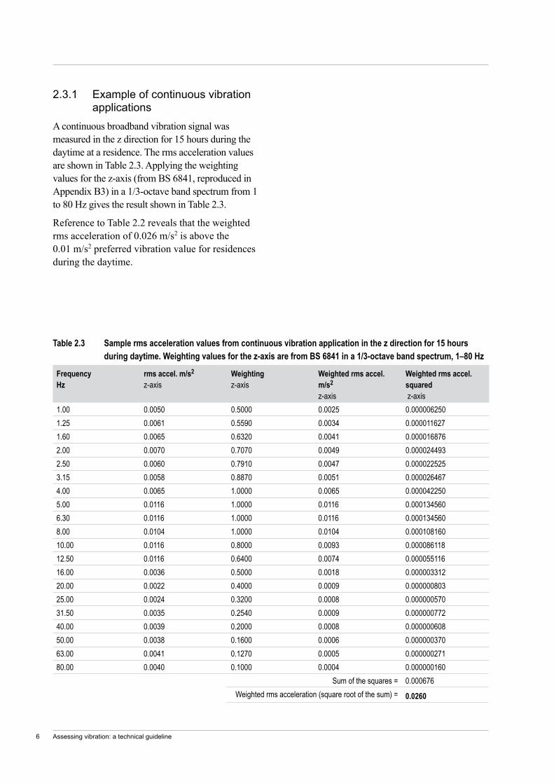
2.3.1 Example of continuous vibration applications
A continuous broadband vibration signal was measured in the z direction for 15 hours during the daytime at a residence. The rms acceleration values are shown in Table 2.3. Applying the weighting values for the z-axis (from BS 6841, reproduced in Appendix B3) in a 1/3-octave band spectrum from 1 to 80 Hz gives the result shown in Table 2.3.
Reference to Table 2.2 reveals that the weighted rms acceleration of 0.026 m/s2 is above the 0.01 m/s2 preferred vibration value for residences during the daytime.
Frequency Hz
rms accel. m/s2 z-axis
Weighting z-axis
Weighted rms accel.m/s2
z-axis
Weighted rms accel. squared z-axis
1.00 0.0050 0.5000 0.0025 0.0000062501.25 0.0061 0.5590 0.0034 0.0000116271.60 0.0065 0.6320 0.0041 0.0000168762.00 0.0070 0.7070 0.0049 0.0000244932.50 0.0060 0.7910 0.0047 0.0000225253.15 0.0058 0.8870 0.0051 0.0000264674.00 0.0065 1.0000 0.0065 0.0000422505.00 0.0116 1.0000 0.0116 0.0001345606.30 0.0116 1.0000 0.0116 0.0001345608.00 0.0104 1.0000 0.0104 0.00010816010.00 0.0116 0.8000 0.0093 0.00008611812.50 0.0116 0.6400 0.0074 0.00005511616.00 0.0036 0.5000 0.0018 0.00000331220.00 0.0022 0.4000 0.0009 0.00000080325.00 0.0024 0.3200 0.0008 0.00000057031.50 0.0035 0.2540 0.0009 0.00000077240.00 0.0039 0.2000 0.0008 0.00000060850.00 0.0038 0.1600 0.0006 0.00000037063.00 0.0041 0.1270 0.0005 0.00000027180.00 0.0040 0.1000 0.0004 0.000000160
Sum of the squares = 0.000676Weighted rms acceleration (square root of the sum) = 0.0260
Table 2.3 Sample rms acceleration values from continuous vibration application in the z direction for 15 hours during daytime. Weighting values for the z-axis are from BS 6841 in a 1/3-octave band spectrum, 1–80 Hz
Assessing vibration: a technical guideline 7
Location Daytime1 Night-time1
Preferred value Maximum value Preferred value Maximum valueCritical areas2 0.10 0.20 0.10 0.20Residences 0.20 0.40 0.13 0.26Offices, schools, educational institutions and places of worship
0.40 0.80 0.40 0.80
Workshops 0.80 1.60 0.80 1.60
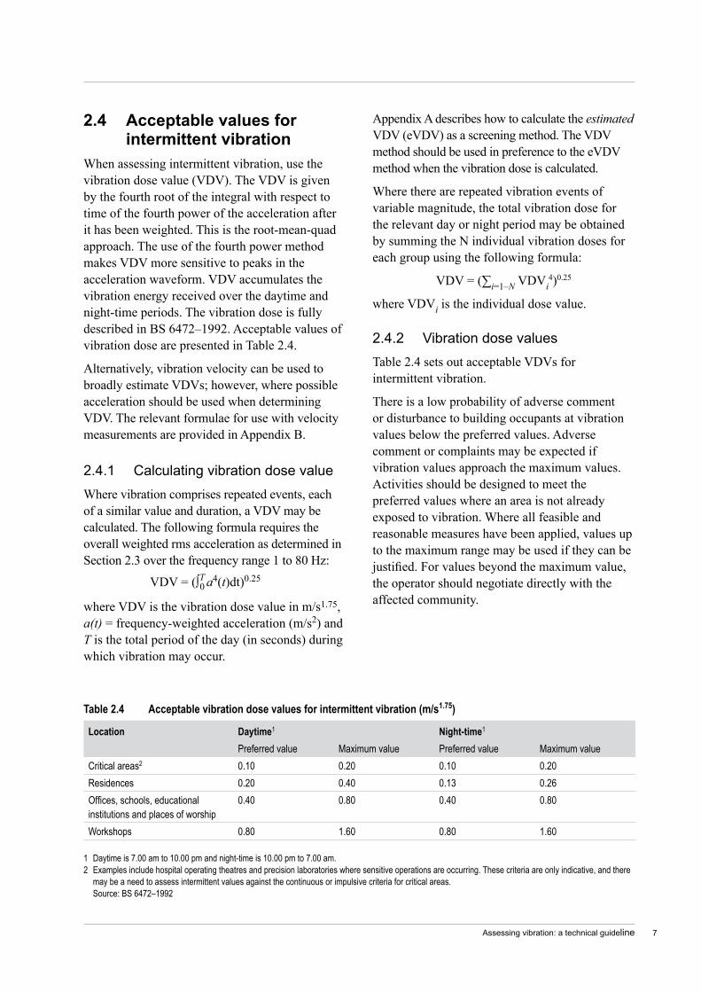
Table 2.4 Acceptable vibration dose values for intermittent vibration (m/s1.75)
1 Daytime is 7.00 am to 10.00 pm and night-time is 10.00 pm to 7.00 am.2 Examples include hospital operating theatres and precision laboratories where sensitive operations are occurring. These criteria are only indicative, and there
may be a need to assess intermittent values against the continuous or impulsive criteria for critical areas. Source: BS 6472–1992
Appendix A describes how to calculate the estimated VDV (eVDV) as a screening method. The VDV method should be used in preference to the eVDV method when the vibration dose is calculated.
Where there are repeated vibration events of variable magnitude, the total vibration dose for the relevant day or night period may be obtained by summing the N individual vibration doses for each group using the following formula:
VDV = (∑i=1–N VDVi4)0.25
where VDVi is the individual dose value.
2.4.2 Vibration dose valuesTable 2.4 sets out acceptable VDVs for intermittent vibration.
There is a low probability of adverse comment or disturbance to building occupants at vibration values below the preferred values. Adverse comment or complaints may be expected if vibration values approach the maximum values. Activities should be designed to meet the preferred values where an area is not already exposed to vibration. Where all feasible and reasonable measures have been applied, values up to the maximum range may be used if they can be justified. For values beyond the maximum value, the operator should negotiate directly with the affected community.
2.4 Acceptablevaluesforintermittentvibration
When assessing intermittent vibration, use the vibration dose value (VDV). The VDV is given by the fourth root of the integral with respect to time of the fourth power of the acceleration after it has been weighted. This is the root-mean-quad approach. The use of the fourth power method makes VDV more sensitive to peaks in the acceleration waveform. VDV accumulates the vibration energy received over the daytime and night-time periods. The vibration dose is fully described in BS 6472–1992. Acceptable values of vibration dose are presented in Table 2.4.
Alternatively, vibration velocity can be used to broadly estimate VDVs; however, where possible acceleration should be used when determining VDV. The relevant formulae for use with velocity measurements are provided in Appendix B.
2.4.1 Calculating vibration dose valueWhere vibration comprises repeated events, each of a similar value and duration, a VDV may be calculated. The following formula requires the overall weighted rms acceleration as determined in Section 2.3 over the frequency range 1 to 80 Hz:
where VDV is the vibration dose value in m/s1.75, a(t) = frequency-weighted acceleration (m/s2) and T is the total period of the day (in seconds) during which vibration may occur.
VDV = (∫T a4(t)dt)0.250
Assessing vibration: a technical guideline8
The company then began to use a deep-level vibro-compaction unit around the piles. Vibration from this unit resulted in complaints to the local council from neighbouring residents concerned about potential structural damage to their buildings.
As the complaints were arriving, the company undertook further compaction tests and found that the upper 3 metres of the sand layer was not compacted to a stable level. To remedy this the company then began using a large, heavy steel plate dropped from a height to compact the upper sand layer around the piles after the deep level vibro-compactor had moved to the next pile.
The result of this strategy was to expose residents to a significant intermittent vibration level. Residents began to experience cosmetic damage to the interior of their apartments and demanded that council take action. Council gave the company a notice of intention for works to stop.
The company met with the most concerned residents of the neighbouring apartment buildings, which consisted of at least 750 units, in their individual apartments, to assess damage and monitor the noise and vibration that each resident experienced. The company also trialled dropping the steel plate from various levels to determine whether there was an acceptable height that would both achieve the level of compaction required and alleviate the residents’ concern. The company settled on dropping the plate from three-quarters of the initial height.
At the same time, council undertook separate vibration testing and concluded that although the level of vibration produced from the three-quarter drop would not result in structural damage to surrounding buildings, it would still cause annoyance to neighbours. Council served an order on the company, requiring it to cease all works onsite until it was able to provide a construction methodology that would satisfy council that residents would not be affected. This order effectively put an end to the continued use of dropping the steel plate.
2.5 Short-termworksWhen short-term works such as piling, demolition and construction give rise to impulsive vibrations, undue restriction on vibration values may significantly prolong these operations and result in greater annoyance. Short-term works are works that occur for a duration of approximately one week.
In circumstances where work is short term, feasible and reasonable mitigation measures have been applied, and the project has a demonstrated high level of social worth and broad community benefits, then higher vibration values (above the maximum) may apply. In such cases, best management practices should be used to reduce values as far as practicable, and a comprehensive community consultation program should be instituted. An example of a possible management strategy would be to restrict the times during which high vibration values occur to the least sensitive times of the day. Typical issues covered in a consultation program include a public contact point for handling complaints, and early notification of proposed operations and any significant change to operations.
2.5.1 Example of managing vibration impacts from construction
Necessity is the mother of invention—alternative work practices can be found when there is a pressing need to do so.
A construction company began piling works for a new apartment building in an inner city suburb. This building represented a late stage of the total redevelopment of their site and involved installing piles into a mud and sand layer, each pile being approximately 20 metres in depth. Approximately 85 piles needed to be installed across the site.
During this part of the construction phase the company undertook stability tests on the completed piles and found that the surrounding soil required compaction. Although this was an unforseen event, it could be easily remedied through standard compaction techniques.
Assessing vibration: a technical guideline �
Representatives of the company met with council and put forward a methodology that they were convinced would alleviate residents’ concerns about annoyance from vibration. This involved the use of a 25-tonne roller, which council allowed on the proviso that the noise levels were within a specified range and that this method of compaction was used only on conclusion of the deep level vibration compaction method. Council accepted this methodology on the basis that as soon as a ‘reasonable complaint’ was received from an affected resident, then site works would have to cease and another methodology would have to be found.
The company also sent potentially affected residents a newsletter informing them of their alternative methodology for site compaction works, when its use would begin and expected operating timeframes. No further complaints were received about compaction vibration from this site.
Assessing vibration: a technical guideline10
3.1 IntroductionSection 2 provides criteria that should be applied when the effects of vibration emissions from industry, transportation and machinery are evaluated and assessed. When the predicted vibration value exceeds the preferred value, then mitigation measures to meet the preferred value should be considered. The degree of vibration impact will determine the extent of mitigation required and the mix of vibration control measures to be adopted as a mitigation strategy. This policy focuses on achieving the desired environmental outcomes so that the vibration source manager is given maximum flexibility in controlling the vibration. Although no prescribed management or mitigation strategies are dictated, the sections below provide guidance on what might be appropriate.
Selecting an appropriate strategy for a proposed development or alterations to an existing development involves the following steps:
1 Determine the vibration reduction required to achieve the preferred vibration values.
2 Identify any project-specific or site-specific constraints or opportunities.
3 Investigate mitigation strategies adopted by similar industries on similar sites.
4 Consider the range of mitigation options available.
5 Consider community preferences for particular strategies. This is especially important when the community has particular sensitivities to vibration.
There are essentially three main mitigation strategies for vibration control:
controlling vibration at the source (Section 3.2)
controlling the transmission of vibration (Section 3.3)
controlling vibration at the receiver (Section 3.4).
••
•
3 Mitigation
Vibration is generally treated by reducing the dynamic forces associated with the source or by isolation techniques. The source may be isolated from the ground or structure, thereby reducing the vibration propagating towards receiver buildings. Alternatively, structures and buildings may be isolated from sources.
The actual values of building vibration induced by sources are a function of the vibration characteristics of the source, ground conditions, building foundations and building construction material and techniques.
The management of short-term exceedances for which mitigation is impractical is discussed in Section 3.5.
3.2 Controllingvibrationatthesource
The principles of ‘best management practice’ (BMP) and ‘best available technology economically achievable’ (BATEA) should be applied.
BMP is the adoption of particular operational procedures that minimise vibration impacts while retaining productive efficiency. Examples could include:
choosing alternative, lower-impact equipment or methods wherever possible
scheduling the use of vibration-causing equipment, such as jackhammers, at the least sensitive time of day
routing, operating or locating high vibration sources as far away from sensitive areas as possible
sequencing operations so that vibration-causing activities do not occur simultaneously
isolating the equipment causing the vibration on resilient mounts
keeping equipment well maintained.
•
•
•
•
•
•

Assessing vibration: a technical guideline 11
BATEA includes equipment, plant and machinery which incorporate the most advanced and affordable technology to minimise vibration output. Where BMP fails to achieve the required vibration reduction by itself, the BATEA approach should be considered. Examples of these strategies for various sources follow.
Blast vibrationCriteria for blast vibration are contained in ANZECC (1990). Blast vibration values may be controlled by careful attention to blast details and the application of correct techniques.
RoadsThe most severe vibrations associated with road traffic result from heavy vehicles with stiff suspensions moving rapidly along roads with irregular surfaces. Mitigation techniques could therefore include the restriction of use of heavy vehicles on particular roads, limiting speed and reducing the occurrence of surface irregularities such as potholes and speed humps.
RailwaysFor railways, jointed rail could be replaced by continuous welded rail in rail lines passing near sensitive premises. Rail vibration isolation systems include resilient rail fastenings, ballast mats and floating slabs. Rolling stock controls include keeping wheels regularly maintained.
ConstructionThere are several strategies for managing vibration from construction sites:
inform neighbours about the nature of the construction stages and the vibration-generating activities—e.g. excavation and rock-breaking
use alternatives to impact piling—bored piling, grip jacking, or the use of a hammer cushion when driving steel piles that minimise the vibration generated
organise demolition, earthmoving and ground-impacting operations so as not to occur in the same time period
•
•
•
avoid night-time activities wherever possible to minimise impact on residential receivers
place as much distance as possible between the plant or equipment and the receivers
select demolition methods not involving impact where possible (e.g. hydraulic rock splitters rather than rock breakers).
Industrial plantAt the initial design stage it is preferable to select machines that are inherently free of vibration. Vibration-producing machinery should be supported on stiff structural components, and be provided with efficient vibration isolation systems.
Structural vibration caused by machinery could be caused by the rotation of poorly balanced parts such as fans, fly wheels, pulleys, cams and shafts. Measures used to correct this condition involve the addition of balance weights to the rotating unit or the selective removal of mass from the unit.
Inertia blocks can be used to add system mass to reduce vibration. They reduce motion, lower the centre of gravity, minimise the effect of unequal weight distribution and stabilise the assembly.
Mechanical vibration passes easily through rigid structures. Vibration isolators reduce vibration by acting as breaks in the vibration transmission path. For effective control, the vibrating unit must be isolated from any connective structures. The types of vibration isolators include:
resilient matting—pads made of neoprene or neoprene and cork. Typically used on air conditioners, business machines, transformers, pumps etc.
spring mounts—spring mountings are used where some limitation of horizontal movement is required, e.g. free-standing spring type with spring location cups at top and bottom and a ribbed neoprene acoustic pad bonded to the underside of the base. Typically used on refrigeration compressors, hydrant pumps, cooling towers and chillers
rubber mounts—typically used on fans, pumps and general industrial equipment
•
•
•
•
•
•
Assessing vibration: a technical guideline12
isolation hangers—typically used for piping, duct work, fans, packaged air conditioners, suspended ceilings etc.
floating floor—false concrete floors can be supported on integral jacking mounting systems to provide support and acoustical isolation. Typically used in plant rooms, theatres, multi-storey buildings and hospitals.
To reduce machine vibration, such as in engines, compressors, air conditioners and fan coil units, isolation mounting should be considered. The mountings should be located to prevent the machine from rocking excessively. The selection of the mounting will depend on the static weight of the equipment, the dynamic reaction force and the reaction forces at start up. Mountings should be installed so that there are no rigid connections between the equipment and the structure.
3.3 Controllingthetransmissionofvibration
Distance is one of the most effective mitigation measures against noise and vibration, although geological make-up and terrain also have an effect. For example, some studies have shown that annoyance from railway vibrations is inversely proportional to distance from railway tracks, with a rapid decrease in vibration disturbance as the distance increases from 25 to 150 metres and a slower rate of reduction over 200 metres, until no vibration disturbance is detected at 500 metres (DUAP, 1997).
3.4 Controllingvibrationatthereceiver
Land-use planning is a critical component in managing vibration impacts. Planning decisions can create or avoid vibration impacts. Decisions that do not consider vibration impacts (where they are present) will almost certainly create land-use conflicts. At the initial planning stage it may be feasible to reduce or avoid vibration impacts by locating less vibration-sensitive land uses (e.g. active recreation, industry) in the intervening land between the existing vibration-
•
•
causing development and sensitive receivers. Alternatively, at the building stage, special building methods could be used to modify ground-borne vibration being transmitted into the building structure (e.g. isolation of foundation and footings using resilient elements such as rubber bearing pads or springs).
The economic viability of vibration control at existing receivers affected by an existing vibration source is dependent on the number of receivers to be treated and the degree of treatment required. The cost-effectiveness may also depend on whether there are a large number of potential receivers who may require attenuation in the future.
3.5 Managingshort-termexceedanceofapprovedvibrationvalues
From time to time, managing vibration at the source may require a short-term increase in vibration beyond the value approved. Such situations may include:
piling, demolition and construction
abnormal operations due to unforeseen breakdown or maintenance requirements.
Mitigation strategies may be impractical for such short-term events.
The vibration-source manager should demonstrate that all alternatives have been considered before seeking an accommodation from the relevant regulatory or consent authority to operate in excess of the agreed vibration values. If it is judged that such an accommodation for a short-term operation is warranted, the following options could be considered:
confining vibration-generating operations to the least vibration-sensitive part of the day—which could be when the background disturbance is highest
determining an upper level for vibration impact also considering what is achievable using feasible and reasonable mitigation
consulting with the community regarding the proposed events.
••
•
•
•

Assessing vibration: a technical guideline 13
3.6 NegotiationWhere maximum values in Tables 2.2 and 2.4 cannot be met after all feasible and reasonable measures have been applied, any unacceptable impacts may be dealt with through negotiation—either by improved mitigation or by trade-offs with benefits. Negotiation can occur between the operator and the regulator or between the operator and the affected community. In the latter case, negotiation should be made available to those people whose amenity is potentially affected by non-achievement of the relevant vibration criteria. This type of negotiation process, which leads to the determination of an achievable vibration limit, is additional to the type of direct consultation that typically occurs between the operator and the community throughout the impact assessment process in defining the important project parameters.
It is important that, as far as possible, the vibration assessment quantify any remaining or residual impacts that exceed the criteria. The acceptability of the residual vibration impacts should be evaluated by taking into consideration factors such as characteristics of the areas and receivers likely to be affected, characteristics of the proposal and its noise and vibrations, the feasibility of additional mitigation or management measures, and generational and community equity issues. For more detail, see the checklist in Section 8.2.1 of the NSW Industrial noise policy (EPA, 2000).
Representatives of the community could have equal status in the negotiating process with the operator, and with any other parties (such as DEC, councils, and the Department of Planning) acting in an advisory capacity.
Meetings could be chaired by an independent facilitator, depending on the circumstances.
Ideas for community consultation (DUAP, 2001) provides a useful resource on principles and methods of community consultation and negotiation.
Assessing vibration: a technical guideline14
4.1 UnitsofmeasurementThe criteria presented in Section 2 are expressed as (or in the case of Table 2.4, based on) rms acceleration. Overall weighted rms acceleration values are used to assess compliance with the criteria. Building vibration may also be measured in rms velocity or peak velocity. Appendix C contains equivalent criteria presented in these terms. Sufficient justification should accompany whichever approach is used in an assessment.
4.2 Locationanddirectionofvibrationmeasurement
As far as is practical, vibration measurements and assessment criteria should refer to the place at which the vibration affects people, which, for this guideline, is inside buildings.
Depending on whether occupants are standing, sitting or lying down, vibration may enter the body in the x-axis, y-axis or z-axis. People are more sensitive to z-axis vibration than to x- and y-axis vibration. However, human exposure to vibration should usually be measured in all three axes, so that the results can be combined and compared to the criteria.
Restrictions on access to buildings often make it necessary for measurements to be made outdoors or at a point other than where the vibration effects are experienced. In such cases, an appropriate transfer function should be used to convert levels at the measurement point to those likely to occur at the assessment point inside the building. As far as is practical, testing should be carried out, or the results of existing studies should be used, to determine the appropriate transfer function. As a screening method, if criteria are met in the ground outside they may also be met inside, and therefore no further work would normally be required in this case.
However, special care should be taken in situations where there may be resonance effects in floors and walls, as vibration values inside
4 Vibration measurement and prediction
buildings may be higher than in the ground immediately outside. Although there is wide variation from structure to structure, in these situations vertical vibration could be at least twice as high. The multiplying factors for horizontal vibration are often lower.
In multi-storey buildings, ground vibration values from external sources tend to diminish with increasing height. The rate of decrease per floor is highly dependent on such factors as distance to the vibration source, the type of building structure and the plan area of each level of the building.
Care also needs to be taken when people are sitting or lying on soft furnishings. High-frequency floor vibration can be reduced by the furnishings, but situations can occur where low-frequency vibration (usually below 10 Hz) is amplified by resonance effects caused by the combined effects of body weight and support stiffness.
4.3 Measurementinstrumentationandtechniques
A single instrumentation system is unlikely to meet all the requirements of frequency and dynamic range under the wide range of situations for which this guideline applies. In general, a vibration measuring system usually includes the following instrumentation:
transducers, typically piezoelectric accelerometers or geophones
signal-conditioning equipment
a data recording and analysis system.
Performance characteristics for the measurement instrumentation should meet the requirements set out in BS 6841 and BS 7482 Parts 1 and 3.
A dynamic range of 40 dB is adequate for most purposes, but 50 dB is preferred. The signal-to-noise ratio (with respect to the background vibration) should generally be not less than 5 dB.
•
••

Assessing vibration: a technical guideline 15
If the signal-to-noise ratio is between 10 dB and 5 dB, the measured value should be corrected (i.e. diminished), and the correction method should be reported. Background vibration, in relation to vibration measurement, is defined as the sum of all the signals not due to the phenomenon under investigation.
4.4 Mountingofvibrationtransducersonbuildings
The mounting of vibration transducers to vibrating elements or substrate should generally comply with Australian Standard AS 2775–2004 Mechanical vibration and shock—Mechanical mounting of accelerometers. The aim should be to reproduce faithfully the motion of the element or substrate without introducing additional response. Care should be taken with triaxial assemblies to avoid rocking or bending.
The mass of the transducer and monitoring unit (if any) should not be greater than 10 per cent of that of the building element to which they are fixed. Mountings should be as stiff and as light as possible. Care should be taken with some velocity transducers (geophones), which are often heavier than accelerometers.
Avoid brackets. It is better to fix three uniaxial transducers to three faces of a metal cube rigidly mounted by means of studs or quick-setting, high-modulus resin. The transducer mounting can be secured to the structure of the building by expansion bolts or rigid-type adhesives.
In special circumstances, it is acceptable to glue the transducer or attach it using magnetic attraction. Do not use double-sided foam tape under any circumstances.
Measurements on floors having soft coverings such as carpet or soft vinyl tiles tend to give distorted results and should be avoided. Where it is not possible to relocate the transducers, make comparative measurements with different mass and coupling conditions for the mounting block to evaluate the effect of the soft coverings.
More information can be obtained from Scannell (1995).
4.5 Mountingofvibrationtransducersontheground
The transducer should be firmly mounted so that the ground vibration is accurately measured. The mounting method that is required is related to the magnitude of vibration as well as the frequency. Refer to Australian Standard AS 2775–2004 Mechanical vibration and shock—Mechanical mounting of accelerometers. Incorrect coupling of the transducer to the ground may lead to erroneous recordings.
When the measurement surface consists of rock, asphalt or concrete, the transducer should be fastened to the measurement surface with a bolt or with epoxy or other quick-setting, rigid cement.
Where soil conditions permit, the transducer may be fixed to a stiff steel or aluminium ‘star-stake’ driven through a loose surface layer. This stake should not project more than a few millimetres above ground surface. Take care to ensure close contact between the transducer star-stake and the ground.
Where transducers have to be mounted in softer ground, to minimise coupling distortion they may be buried (and well tamped) to a depth at least three times the main dimension of the transducer or mounting unit. Alternatively, they can be fixed to a rigid surface plate (e.g. a well-bedded paving slab).
The transducer should be located at a sufficient distance from any structure (including large trees) so as to avoid undue interference from vibration ‘feeding back’ from the structure. The required distance away will be specific to site and structure and would need to be determined for each case. The transducer should be orientated as recommended by the manufacturer in the direction of the vibration source.

Assessing vibration: a technical guideline16
4.6 PredictionProcedures currently used for predicting ground-borne vibration are based on a combination of measurement and the use of formulas derived from actual experience. Examples of such assessment procedures are included in documents such as the US Federal Transit Administration’s Transit noise and vibration impact assessment (1995) and the Transport Research Laboratory’s Groundborne vibration caused by mechanised construction works (Hiller & Crabb, 2000). It is important that any method or procedure used to predict vibration be clearly described and validated before use (e.g. via test measurements and calculations, published studies, comparison with existing databases etc). All assumptions used in the prediction should be clearly stated, and the expected accuracy should be quoted along with the final predicted values.
Where new projects are proposed, predictions should be conducted for two scenarios: proposed start date and 10 years from the date of commencement. Where mitigation measures are being proposed, predictions should be conducted for both the before and after mitigation situations, and a mitigation strategy should be prepared and based on the worst case from both the date of commencement and 10 years hence.
4.7 Informationprovidedinavibrationassessmentreport
A vibration assessment report should include at least the following information:
project descriptionrelevant guideline or policy that has been applieddetails of any background measurements that have been undertakendetails of instruments and methodology used for measurements (including reasons for settings and descriptors used and calibration details)a site map showing location of vibration sources, measurement locations and receivers (where appropriate)vibration criteria applied to the projectvibration predictions for the proposed activitya comparison of predictions against vibration criteriaa discussion of proposed mitigation measures, the vibration reduction likely and the feasibility and reasonableness of these measureshow compliance can be practically determined.
••
•
•
•
•••
•
•
Assessing vibration: a technical guideline 17
Allen DE, 1990. Building vibrations from human activities. Concrete International 12(6): 66–73.
ANSI S3.29–1983 Guide to the evaluation of human exposure to vibration in buildings. American National Standards Institute, Washington DC.
ANZECC 1990. Technical basis for guidelines to minimise annoyance due to blasting overpressure and ground vibration. Australian and New Zealand Environment Council, Canberra.
Arnberg PW, Bennerhult O, Eberhardt JL, 1990. Sleep disturbances caused by vibrations from heavy road traffic. Journal of the Acoustical Society of America 88(3): 1486–1493.
Association of Noise Consultants, 2001. Guidelines—measurement and assessment of groundborne noise and vibration. Fresco, Hertfordshire, UK.
AS 2187.2–1993 Explosives—Storage transport and use. Part 2: Use of explosives.
AS 2606–1993 Vibration and shock—vocabulary.
AS 2670.1–1990 Evaluation of human exposure to whole body vibration. Part 1: General requirements (superseded).
AS 2670.1–2001 Evaluation of human exposure to whole-body vibration. Part 1: General requirements.
AS 2670.2–1990 Evaluation of human exposure to whole body vibration. Part 2: Continuous and shock induced vibration in buildings (1 to 80 Hz).
AS 2670.3–1990 Evaluation of human exposure to whole body vibration. Part 3: Evaluation of exposure to whole body x axis vertical vibration in the frequency range 0.1 to 0.63 Hz.
AS 2775–2004 Mechanical vibration and shock—Mechanical mounting of accelerometers.
AS 2973–1987 Vibration and shock—Human response—Vibration measuring instrumentation.
References and bibliography
AS 3658–1989 Vibration and shock—Mechanical vibration and shock affecting humans—vocabulary.
BS 6472–1984 Evaluation of human exposure to vibration in buildings (1 Hz to 80 Hz).
BS 6472–1992 Guide to evaluation of human exposure to vibration in buildings (1 Hz to 80 Hz).
BS 6841–1987 Guide to measurement and evaluation of human exposure to whole-body mechanical vibration and repeated shock.
BS 7482–1991 Parts 1 and 3: Instrumentation for the measurement of vibration exposure of human beings.
Clark D, Larsson B, Lande G, 1983. Vibration: its effect and measurement techniques at or near dwellings. VME-Nitro Consult Inc., Louisville, Kentucky, USA.
DIN 4150 1999. Part 2, Structural vibration —Human exposure to vibration in buildings.
DIN 4150, 1999. Part 3, Structural vibration —Effects of vibration on structures.
DUAP, 1997. Assessment of noise, vibration and blasting impacts. EIS manual. Department of Urban Affairs and Planning, Sydney.
Carson L, Gelber K, 2001. Ideas for community consultation—principles and procedures. Department of Urban Affairs and Planning, Sydney.
Embelton Ltd, 1989. Vibration isolation and control—selection guide. Embelton, Melbourne.
EPA, 1994. Environmental noise control manual. Environment Protection Authority, Sydney.
EPA, 2000. New South Wales Industrial noise policy. Environment Protection Authority, Sydney.
Federal Transit Administration, 1995. Transit noise and vibration impact assessment. Report prepared by Harris Miller Miller & Hanson Inc. for Federal Transit Administration, Washington DC.
Assessing vibration: a technical guideline18
Goldberg JL, Drew P, 1980. The response of high-rise and domestic buildings to ground vibration from blasting. Paper for Tenth International Congress on Acoustics, Sydney, 9–16 July 1980, CSIRO Division of Applied Physics, Sydney.
Griffin MJ, Whitham EM, 1980. Discomfort produced by impulsive whole body vibration. Journal of the Acoustical Society of America, 68: 1277–1284.
Hiller DM, Crabb GI, 2000. Groundborne vibration caused by mechanised construction works. TRL Report 429, Transport Research Laboratory, Berkshire, England.
Howarth HVC, Griffin MJ, 1988. Human response to simulated intermittent railway induced building vibration. Journal of Sound and Vibration, 120(2): 413–420.
ISO 2631.1–1997 Mechanical vibration and shock —Evaluation of human exposure to whole body vibration. Part 1: General requirements.
ISO 2631.2–1989 Evaluation of human exposure to whole body vibration. Part 2: Continuous and shock induced vibration in buildings (1 Hz to 80 Hz) (superseded).
ISO 2631.2–2003 Mechanical vibration and shock —Evaluation of human exposure to whole-body vibration. Part 2: Vibration in buildings (1 Hz to 80 Hz).
Nelson PM, 1987. Transportation noise reference book. Butterworth, London.
Saurenman HJ, Nelson, JT, Wilson GP, 1982. Handbook of urban rail noise and vibration control. Report No UMTA MA 06 0099 82 1. US Department of Transportation, Urban Mass Transportation Administration, Washington DC.
Scannell K, 1995. Practical aspects of investigating complaints from vibration in buildings. Journal of Building Acoustics 2(3): 413–517.
Siskind DE, Stagg MS, Kopp JW, Dowding CH, 1980. RI 8507 Structure response and damage produced by ground vibration from surface mine blasting. US Bureau of Mines, Pittsburgh, PA.
Ungar EE, Gordon CG, 1985. Cost-effective design of practically vibration-free high technology facilities. American Society of Civil Engineers, New York.
Assessing vibration: a technical guideline 1�
A1 Continuousandimpulsivevibration
As a screening method, the overall unweighted rms acceleration could be assessed against the preferred values contained in Tables 2.2 and 2.4. This represents a conservative approach to demonstrating compliance or the need to use the more precise approach using appropriate frequency weightings.
Alternatively, overall unweighted vibration velocity could be used for assessment. For vibration predominantly in the frequency range 8 to 80 Hz, rms velocity can be used as a screening parameter, as this closely represents the weighting curve. The relevant assessment criteria for velocity are listed in Appendix C.
Any assessment which uses the screening method rather than comparison of the weighted values against the criteria should clearly state that the data are based on the screening method and present the measurement parameter used (such as rms velocity or rms acceleration). Sufficient justification should accompany whichever approach is used in an assessment.
A2 IntermittentvibrationThe crest factor is the ratio between the peak level (without time response) and the rms value of a signal. As a screening method for intermittent vibration, the eVDV equation can be used for crest factors below 6. The eVDV is obtained as follows:
eVDV = k × a rms × t 0.25
where k is nominally 1.4 for crest factors below 6, arms = weighted rms acceleration (m/s2) and t = total cumulative time (seconds) of the vibration events(s) or period(s) of vibration.
For crest factors above 6, the eVDV equation might no longer accurately represent the vibration dose, so the VDV equation should be used instead (see Section 2.4.1).
Appendix A Screening method
Where the vibration varies in magnitude over time in a more complex fashion, the rms acceleration value should be measured over representative time periods. Each individual time period should have a crest factor of less than 6. The eVDV can then be calculated with the above formula.
ExampleA vibratory roller is being used during construction of a car park near an office block. The vibration values on the office floor are constantly varying, and cannot be segregated into groups or periods of similar vibration value. The weighted acceleration value a was measured to be 0.032 m/s2 over a 3-hour period of roller work in the morning, and then 0.055 m/s2 over 2 hours in the afternoon.
The estimated vibration doses, eVDV, are given as follows.
For the 3-hour morning exposure:
eVDV = 1.4 × a × t 0.25
= 1.4 × 0.032 × (3 × 60 × 60)0.25
= 0.46 m/s1.75
For the 2-hour afternoon exposure:
eVDV = 1.4 × 0.055 × (2 × 60 × 60)0.25
= 0.71 m/s1.75
The total estimated vibration dose over the full day (5 hours’ vibration) is:
eVDV = (0.464 + 0.714)0.25 = 0.74 m/s1.75
Reference to Table 2.4 indicates that this vibration dose clearly exceeds the preferred value of 0.4 m/s1.75. Hence, adverse effects are expected, and mitigation measures should be investigated to reduce the effects of vibration.
•
•
Assessing vibration: a technical guideline20
B1 Valuesforcontinuousandimpulsivevibration
Human discomfort values for continuous vibration have been extensively researched and published in BS 6472 (1984 and 1992), ISO 2631.2–1989 and AS 2670.2–1990, which form the basis of this guideline. References and a bibliography identifying the research studies are included in each of these standards.
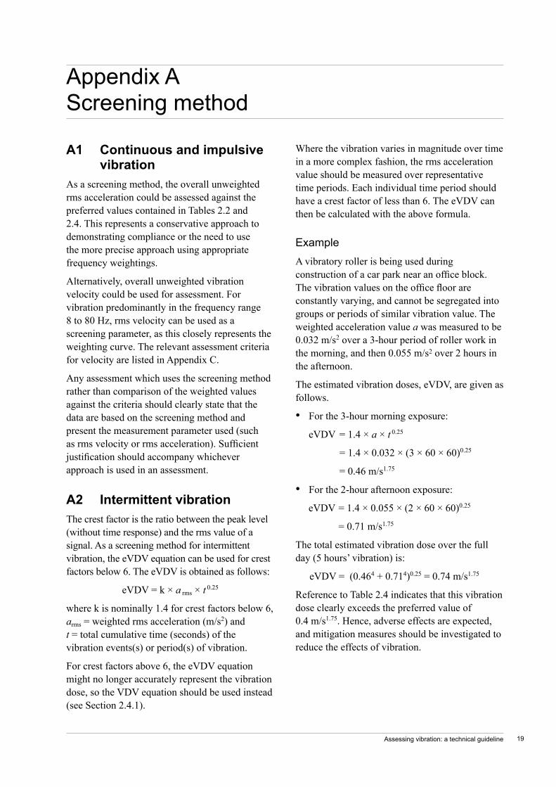
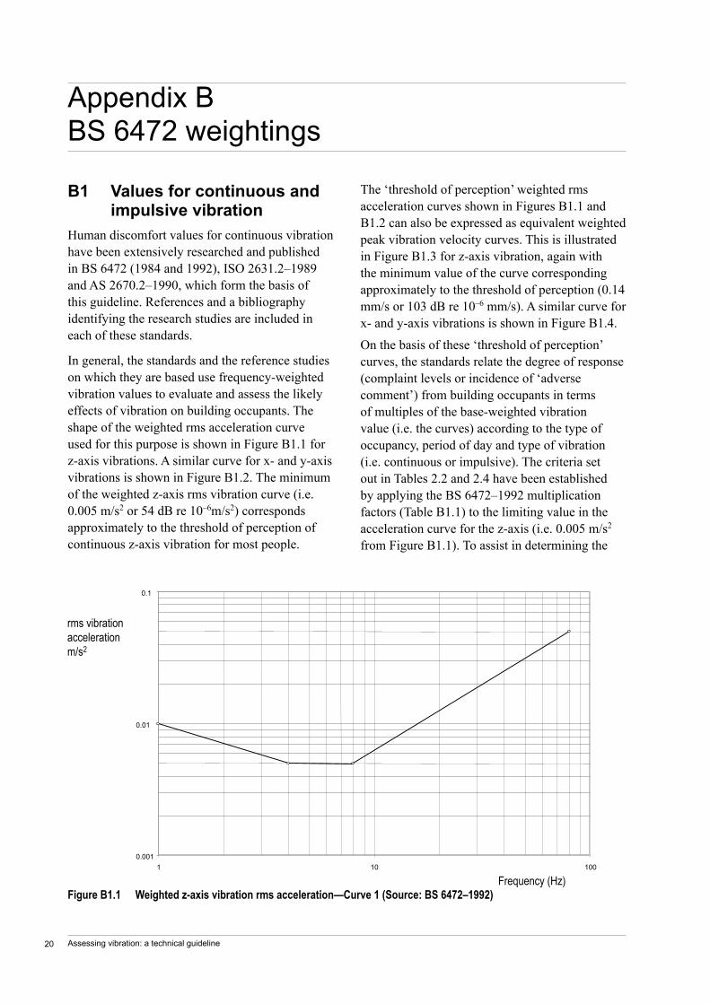
In general, the standards and the reference studies on which they are based use frequency-weighted vibration values to evaluate and assess the likely effects of vibration on building occupants. The shape of the weighted rms acceleration curve used for this purpose is shown in Figure B1.1 for z-axis vibrations. A similar curve for x- and y-axis vibrations is shown in Figure B1.2. The minimum of the weighted z-axis rms vibration curve (i.e. 0.005 m/s2 or 54 dB re 10–6m/s2) corresponds approximately to the threshold of perception of continuous z-axis vibration for most people.
Appendix B BS 6472 weightings
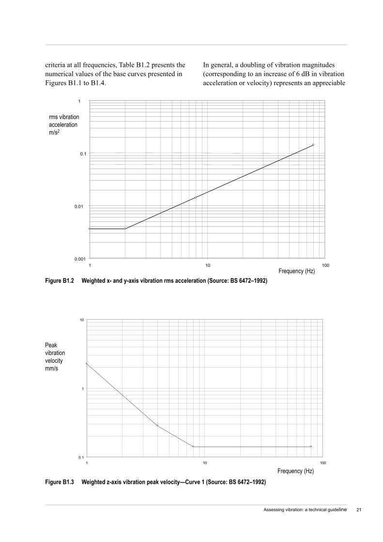
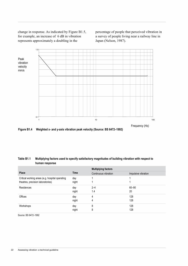
The ‘threshold of perception’ weighted rms acceleration curves shown in Figures B1.1 and B1.2 can also be expressed as equivalent weighted peak vibration velocity curves. This is illustrated in Figure B1.3 for z-axis vibration, again with the minimum value of the curve corresponding approximately to the threshold of perception (0.14 mm/s or 103 dB re 10–6 mm/s). A similar curve for x- and y-axis vibrations is shown in Figure B1.4.
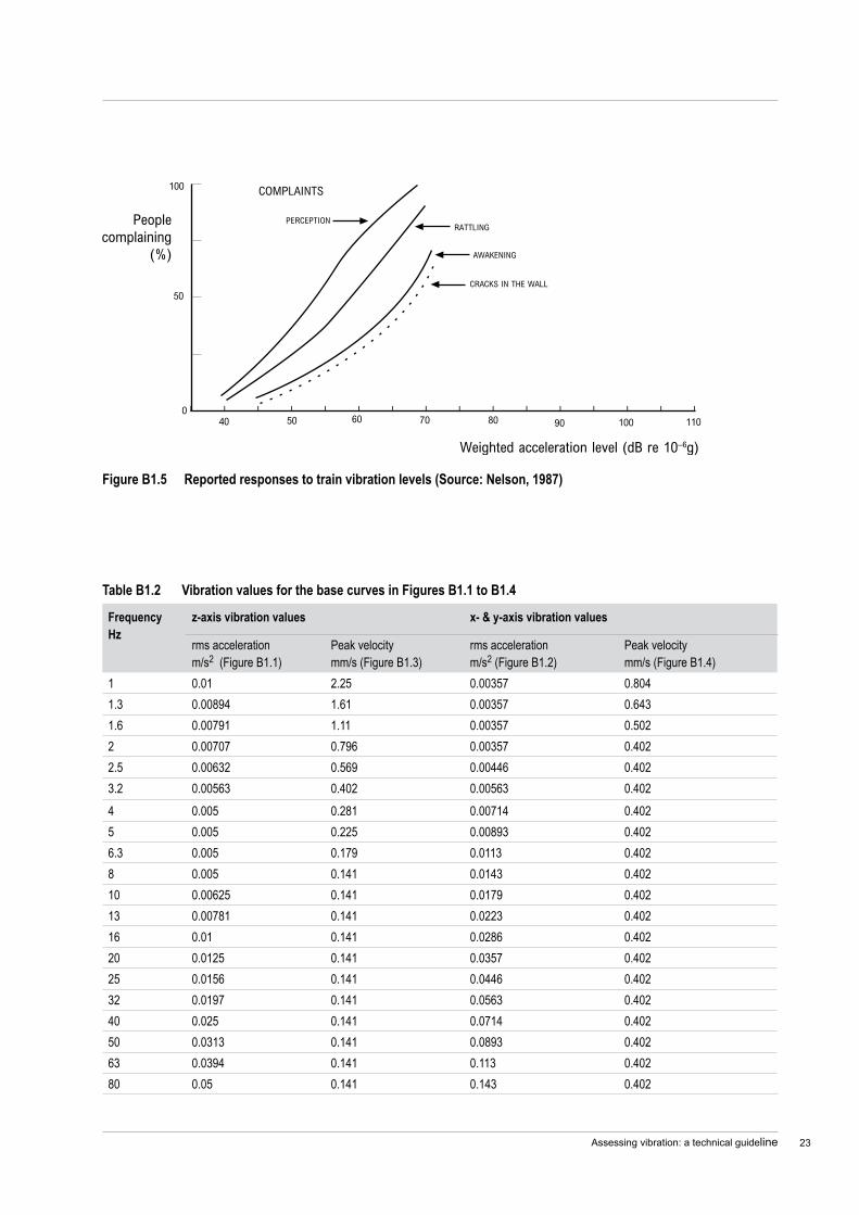
On the basis of these ‘threshold of perception’ curves, the standards relate the degree of response (complaint levels or incidence of ‘adverse comment’) from building occupants in terms of multiples of the base-weighted vibration value (i.e. the curves) according to the type of occupancy, period of day and type of vibration (i.e. continuous or impulsive). The criteria set out in Tables 2.2 and 2.4 have been established by applying the BS 6472–1992 multiplication factors (Table B1.1) to the limiting value in the acceleration curve for the z-axis (i.e. 0.005 m/s2 from Figure B1.1). To assist in determining the
Figure B1.1 Weighted z-axis vibration rms acceleration—Curve 1 (Source: BS 6472–1992)
0.001
0.01
0.1
1 10 100
rms vibrationaccelerationm/s2
Frequency (Hz)
Assessing vibration: a technical guideline 21
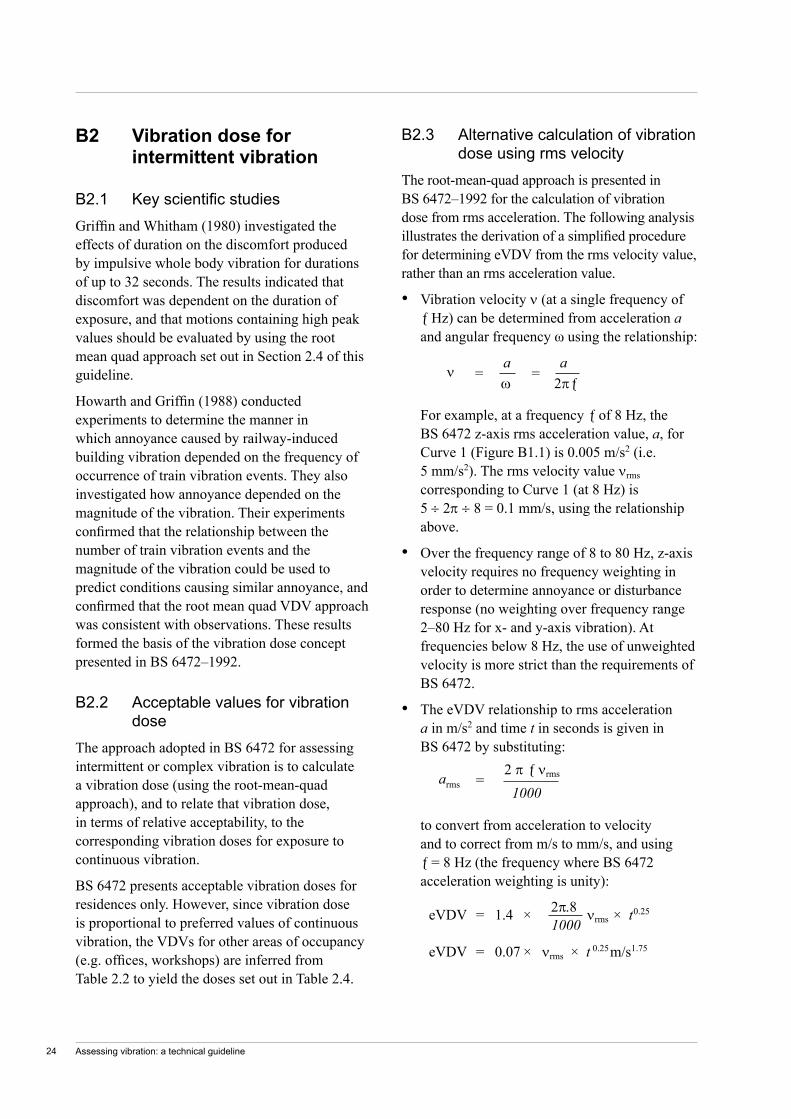
criteria at all frequencies, Table B1.2 presents the numerical values of the base curves presented in Figures B1.1 to B1.4.
0.1
1
10
1 10 100
Peakvibrationvelocitymm/s
Frequency (Hz)Figure B1.3 Weighted z-axis vibration peak velocity—Curve 1 (Source: BS 6472–1992)
In general, a doubling of vibration magnitudes (corresponding to an increase of 6 dB in vibration acceleration or velocity) represents an appreciable
Figure B1.2 Weighted x- and y-axis vibration rms acceleration (Source: BS 6472–1992)
0.001
0.01
0.1
1
1 10 100
rms vibrationaccelerationm/s2
Frequency (Hz)
Assessing vibration: a technical guideline22
change in response. As indicated by Figure B1.5, for example, an increase of 6 dB in vibration represents approximately a doubling in the
percentage of people that perceived vibration in a survey of people living near a railway line in Japan (Nelson, 1987).
Figure B1.4 Weighted x- and y-axis vibration peak velocity (Source: BS 6472–1992)
0.1
1.0
1 10 100
Peakvibrationvelocitymm/s
Frequency (Hz)
Source: BS 6472–1992
Table B1.1 Multiplying factors used to specify satisfactory magnitudes of building vibration with respect to human response
Place
Time
Multiplying factorsContinuous vibration Impulsive vibration
Critical working areas (e.g. hospital operating theatres, precision laboratories)
day night
1 1
1 1
Residences day night
2–4 1.4
60–90 20
Offices day night
4 4
128 128
Workshops day night
8 8
128 128
Assessing vibration: a technical guideline 23
Table B1.2 Vibration values for the base curves in Figures B1.1 to B1.4
Frequency Hz
z-axis vibration values x- & y-axis vibration values
rms acceleration m/s2 (Figure B1.1)
Peak velocity mm/s (Figure B1.3)
rms acceleration m/s2 (Figure B1.2)
Peak velocity mm/s (Figure B1.4)
1 0.01 2.25 0.00357 0.8041.3 0.00894 1.61 0.00357 0.6431.6 0.00791 1.11 0.00357 0.5022 0.00707 0.796 0.00357 0.4022.5 0.00632 0.569 0.00446 0.4023.2 0.00563 0.402 0.00563 0.4024 0.005 0.281 0.00714 0.4025 0.005 0.225 0.00893 0.4026.3 0.005 0.179 0.0113 0.4028 0.005 0.141 0.0143 0.40210 0.00625 0.141 0.0179 0.40213 0.00781 0.141 0.0223 0.40216 0.01 0.141 0.0286 0.40220 0.0125 0.141 0.0357 0.40225 0.0156 0.141 0.0446 0.40232 0.0197 0.141 0.0563 0.40240 0.025 0.141 0.0714 0.40250 0.0313 0.141 0.0893 0.40263 0.0394 0.141 0.113 0.40280 0.05 0.141 0.143 0.402
Figure B1.5 Reported responses to train vibration levels (Source: Nelson, 1987)
Assessing vibration: a technical guideline24
B2 Vibrationdoseforintermittentvibration
B2.1 KeyscientificstudiesGriffin and Whitham (1980) investigated the effects of duration on the discomfort produced by impulsive whole body vibration for durations of up to 32 seconds. The results indicated that discomfort was dependent on the duration of exposure, and that motions containing high peak values should be evaluated by using the root mean quad approach set out in Section 2.4 of this guideline.
Howarth and Griffin (1988) conducted experiments to determine the manner in which annoyance caused by railway-induced building vibration depended on the frequency of occurrence of train vibration events. They also investigated how annoyance depended on the magnitude of the vibration. Their experiments confirmed that the relationship between the number of train vibration events and the magnitude of the vibration could be used to predict conditions causing similar annoyance, and confirmed that the root mean quad VDV approach was consistent with observations. These results formed the basis of the vibration dose concept presented in BS 6472–1992.
B2.2 Acceptable values for vibration dose
The approach adopted in BS 6472 for assessing intermittent or complex vibration is to calculate a vibration dose (using the root-mean-quad approach), and to relate that vibration dose, in terms of relative acceptability, to the corresponding vibration doses for exposure to continuous vibration.
BS 6472 presents acceptable vibration doses for residences only. However, since vibration dose is proportional to preferred values of continuous vibration, the VDVs for other areas of occupancy (e.g. offices, workshops) are inferred from Table 2.2 to yield the doses set out in Table 2.4.
B2.3 Alternative calculation of vibration dose using rms velocity
The root-mean-quad approach is presented in BS 6472–1992 for the calculation of vibration dose from rms acceleration. The following analysis illustrates the derivation of a simplified procedure for determining eVDV from the rms velocity value, rather than an rms acceleration value.
Vibration velocity ν (at a single frequency of ƒ Hz) can be determined from acceleration a and angular frequency ω using the relationship:
For example, at a frequency ƒ of 8 Hz, the BS 6472 z-axis rms acceleration value, a, for Curve 1 (Figure B1.1) is 0.005 m/s2 (i.e. 5 mm/s2). The rms velocity value νrms corresponding to Curve 1 (at 8 Hz) is 5 ÷ 2π ÷ 8 = 0.1 mm/s, using the relationship above.
Over the frequency range of 8 to 80 Hz, z-axis velocity requires no frequency weighting in order to determine annoyance or disturbance response (no weighting over frequency range 2–80 Hz for x- and y-axis vibration). At frequencies below 8 Hz, the use of unweighted velocity is more strict than the requirements of BS 6472.
The eVDV relationship to rms acceleration a in m/s2 and time t in seconds is given in BS 6472 by substituting:
to convert from acceleration to velocity and to correct from m/s to mm/s, and using ƒ = 8 Hz (the frequency where BS 6472 acceleration weighting is unity):
•
•
•
arms =
2 π ƒ νrms
1000
ν
= a
= a
ω 2πƒ
eVDV = 1.4 × 2π.8 νrms × t 0.25
1000
eVDV = 0.07 × νrms × t 0.25 m/s1.75
Assessing vibration: a technical guideline 25
B3 Approximatefrequencyweightingsofbasecurves(1–80Hz)
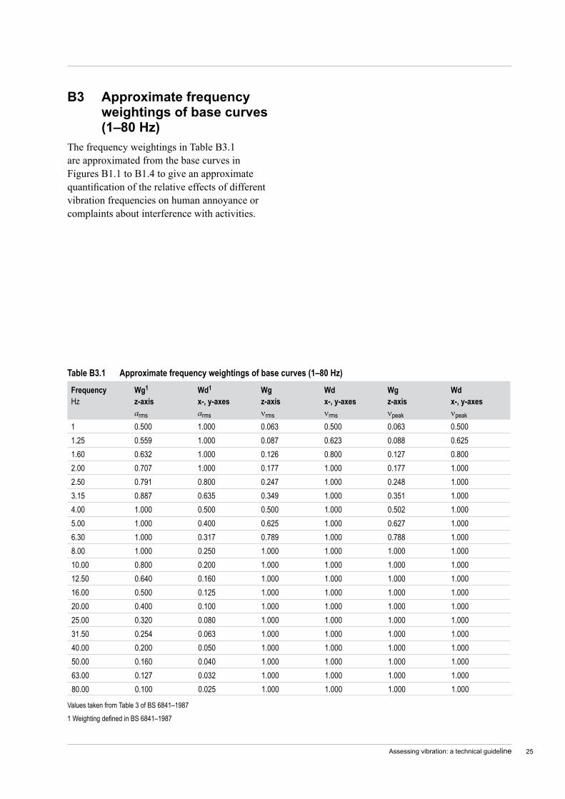
The frequency weightings in Table B3.1 are approximated from the base curves in Figures B1.1 to B1.4 to give an approximate quantification of the relative effects of different vibration frequencies on human annoyance or complaints about interference with activities.
Table B3.1 Approximate frequency weightings of base curves (1–80 Hz)
Values taken from Table 3 of BS 6841–1987
1 Weighting defined in BS 6841–1987
Frequency Hz
Wg1 z-axis arms
Wd1
x-, y-axes arms
Wg z-axis νrms
Wd x-, y-axes νrms
Wg z-axis νpeak
Wd x-, y-axes νpeak
1 0.500 1.000 0.063 0.500 0.063 0.5001.25 0.559 1.000 0.087 0.623 0.088 0.6251.60 0.632 1.000 0.126 0.800 0.127 0.8002.00 0.707 1.000 0.177 1.000 0.177 1.0002.50 0.791 0.800 0.247 1.000 0.248 1.0003.15 0.887 0.635 0.349 1.000 0.351 1.0004.00 1.000 0.500 0.500 1.000 0.502 1.0005.00 1.000 0.400 0.625 1.000 0.627 1.0006.30 1.000 0.317 0.789 1.000 0.788 1.0008.00 1.000 0.250 1.000 1.000 1.000 1.00010.00 0.800 0.200 1.000 1.000 1.000 1.00012.50 0.640 0.160 1.000 1.000 1.000 1.00016.00 0.500 0.125 1.000 1.000 1.000 1.00020.00 0.400 0.100 1.000 1.000 1.000 1.00025.00 0.320 0.080 1.000 1.000 1.000 1.00031.50 0.254 0.063 1.000 1.000 1.000 1.00040.00 0.200 0.050 1.000 1.000 1.000 1.00050.00 0.160 0.040 1.000 1.000 1.000 1.00063.00 0.127 0.032 1.000 1.000 1.000 1.00080.00 0.100 0.025 1.000 1.000 1.000 1.000

Assessing vibration: a technical guideline26
C1 Criteriaforexposuretocontinuousandimpulsivevibration
The criteria presented in Table C1.1 for continuous vibration relate to vibration that continues uninterrupted for a defined period (usually throughout the daytime or night-time), e.g. continuous construction or maintenance activity.
Appendix C Vibration criteria presented in different units
The criteria presented in Table C1.1 for impulsive vibration relate to vibration that builds up rapidly to a peak followed by a damped decay and that may or may not involve several cycles of vibration (depending on frequency and damping), with up to three occurrences in an assessment period, e.g. occasional loading and unloading, or dropping of heavy equipment.
Table C1.1 Criteria for exposure to continuous and impulsive vibration
Place
Time
Assessment criteria1rms acceleration (m/s2) (& vib. accel. value) (dB re 10–6 m/s2)
2rms velocity (mm/s) (& vib. velocity value) (dB re 10–6 mm/s)
2Peak velocity (mm/s)
Preferred Maximum Preferred Maximum Preferred Maximum
Continuous vibration
Critical working areas (e.g. hospital operating theatres, precision laboratories)
Day- or night-time
0.0050 (74 dB)
0.010 (80 dB)
0.10 (100 dB)
0.20 (106 dB)
0.14 0.28
Residences Daytime3 0.010 (80 dB)
0.020 (86 dB)
0.20 (106 dB)
0.40 (112 dB)
0.28 0.56
Night-time 0.0070 (77 dB)
0.014 (83 dB)
0.14 (103 dB)
0.28 (109 dB)
0.20 0.40
Offices Day- or night-time
0.020 (86 dB)
0.040 (92 dB)
0.40 (112 dB)
0.80 (118 dB)
0.56 1.1
Workshops Day- or night-time
0.040 (92 dB)
0.080 (98 dB)
0.80 (118 dB)
1.6 (124 dB)
1.1 2.2
1 Values derived from z-axis critical frequency range 4–8 Hz. Where required, a more detailed analysis can be conducted as per BS 6472–1992.2 Values given for the most critical frequency range >8 Hz assuming sinusoidal motion. Where required, a more detailed analysis can be conducted as per
AS 2670.2–1990. Sufficient justification should accompany the use of a peak velocity approach if used in an assessment.3 Specific values depend on social and cultural factors, psychological attitudes and expected degree of intrusion.
Impulsive vibration
Critical working areas (e.g. hospital operating theatres, precision laboratories)
Day- or night-time
0.0050 (74 dB)
0.010 (80 dB)
0.10 (100 dB)
0.20 (106 dB)
0.14 0.28
Residences Daytime3 0.30 (110 dB)
0.60 (113 dB)
6.0 (136 dB)
12.0 (142 dB)
8.6 17.0
Night-time 0.10 (100 dB)
0.20 (106 dB)
2.0 (126 dB)
4.0 (132 dB)
2.8 5.6
Offices Day- or night-time
0.64 (116 dB)
1.28 (122 dB)
13.0 (142 dB)
26.0 (148 dB)
18.0 36.0
Workshops Day- or night-time
0.64 (116 dB)
1.28 (122 dB)
13.0 (142 dB)
26.0 (148 dB)
18.0 36.0
Assessing vibration: a technical guideline 27
D1 Humansensitivitytovibration
The sensitivity of people to vibration depends on the direction in which the vibration acts and its frequency content. There are also summation effects for complex vibration-containing components at different frequencies. In many instances, however, the ‘filtering’ effect of resonances, buildings and other structures causes vibration energy to concentrate in a narrow frequency band.
In general, satisfactory or ‘acceptable’ magnitudes of vibration are related to the probability of adverse comments from building occupants and are not determined by other factors such as short term health hazards or working efficiency. In dwellings, adverse comments often arise when occupants perceive the vibration, note that it is associated with a source outside their home (or outside their control), and assume that the vibration has potential to damage their building or contents.
People exhibit wide variations of vibration tolerance. Responses depend on social and cultural factors, psychological attitudes, expectations regarding the degree of intrusion and other connotations associated with the sources of vibration (e.g. smell, dust, fear). In dwellings, the magnitudes of vibration considered ‘acceptable’ to most people are barely above thresholds of perception.
In office environments, slightly higher vibration values are usually considered acceptable, as there appears to be an expectation by the occupants that a small level of detectable movement is ‘normal’. Similarly, even higher vibration values are considered acceptable in workshop or factory environments.
In most cases the occupants’ expectations of what is a ‘normal’, safe vibration environment for the surroundings determines the acceptable values, rather than any direct effects on physical comfort or ability to carry out tasks or activities. At values
Appendix D History of vibration criteria
of vibration higher than the acceptable values, more direct adverse effects such as distraction, irritation and subsequent interference with quiet activities or sleep patterns may also occur. The presence of other vibration-related effects (e.g. audible rattling of loose objects, visible movement of household contents and windows), which can also arise at values of vibration that are barely detectable, also tends to heighten concern about vibration and its effects.
D2 Policiesandguidelinesofauthorities
D2.1 StandardsBefore the release of this guideline, DEC’s general guideline for the evaluation and assessment of vibration was set out in Chapter 174 of the Environmental noise control manual. The approach adopted was a subset of BS 6472–1984, Evaluation of human exposure to vibration in buildings (1 Hz to 80 Hz).
The content of the 1984 issue of the British Standard was a precursor to ISO 2631.2–1989, which was published in Australia as AS 2670.2–1990.
In the USA, the still current ANSI S3.29–1983 Guide to the evaluation of human exposure to vibration in buildings (re-confirmed in 1996) contains almost identical guidance to that presented in the 1984 issue of the British Standard.
Since 1984, BS 6472 underwent a further revision and was re-released in 1992 to address what was seen as ISO 2631’s ‘insufficient information to allow proper evaluation of human response to vibration in buildings’. The more recent British Standard conforms in substantial measure with the ISO document, but contains significant additional guidance, and has been updated to take account of developments in vibration evaluation and assessment (particularly in relation
Assessing vibration: a technical guideline28
to complex patterns of vibration and ‘vibration dose’ concepts). A bibliography of data published elsewhere to support the approach adopted in BS 6472–1992 appears in Appendix D to the standard, and key items are listed in the references and bibliography in this guideline.
The latest release of BS 6472 includes information on the evaluation of intermittent vibration by introducing a ‘vibration dose’ concept. This approach can be used for the evaluation and assessment of vibration from trains, heavy road vehicles, construction activity and other vibration sources which are not continuous. These are potential sources of widespread disturbance in the community, and it is therefore important that appropriate techniques be provided for their assessment.
Other issues clarified in the latest version of BS 6472 include improved guidance on the degrees of community response associated with various values of vibration and better illustrative examples of applications of the standard’s procedures.
The revised ISO 2631.1–1997 reflects the 1992 changes in BS 6472, and AS 2670.1–2001 was revised to reflect ISO 2631.1–1997. ISO 2631.2–2003 was redrafted to harmonise it with ISO 2631.1–1997, but at the time of writing the Australian Standard has not yet been revised. ISO 2631.2–2003 does not include guideline values for human comfort, citing the range of values as being too widespread for reproduction in an international standard. It was considered appropriate to update the DEC’s vibration guideline to the approach embodied in BS 6472–1992.
Furthermore, the previous guideline in Chapter 174 of the Environmental noise control manual addresses only z-axis vibration. Given the frequent occurrence of vibration along the x- and y-axes (e.g. due to acoustic excitation, and x- and y-axis ground vibration from some sources), information on evaluation and assessment of vibration along these axes should be provided, and therefore is included in this guideline.
D2.2 Practices adopted in other areas of Australia
At the time of publication, none of the environmental regulatory or protection agencies in other states or territories of Australia have published formal guidelines relating to vibration in buildings.
For the assessment of vibration in general, other states and territories appear to rely on the findings and recommendations of competent investigators engaged by relevant parties to investigate complaints or to assist in planning for new developments. In general, there seems to be reliance on ISO 2631 and BS 6472, in much the same manner as DEC’s previous guideline in Chapter 174 of the Environmental noise control manual.
Other government authorities in NSW (e.g. Railcorp, Australian Railtrack Corporation, Roads and Traffic Authority, Department of Planning, and local councils) have been following DEC’s previous guideline (based on the previous BS 6472) when assessing potential human discomfort from vibration.
Assessing vibration: a technical guideline 2�
Glossary
Annoyance Type of reaction felt by humans in response to vibration. The degree of annoyance felt by an individual may be assessed by using social survey techniques
Best management practices (BMP)The adoption of particular operational procedures that minimise vibration impacts effects while retaining productive efficiency
Best available technology economically achievable (BATEA) Equipment, plant and machinery that incorporates the most advanced and affordable technology to minimise vibration output
Comfort Subjective state of wellbeing in relation to an induced environment such as mechanical vibration (or shock). Comfort connotes the absence of disturbing or intrusive factors.
Crest factor The ratio between the peak level and the rms value of a signal.
DEC Department of Environment and Conservation
eVDV Estimated vibration dose value
Feasible and reasonable measures Feasibility relates to engineering considerations and what is practical to build; reasonableness relates to the application of judgement in arriving at a decision, taking into account the following factors:
vibration mitigation benefits (amount of vibration reduction provided, number of people protected)
cost of mitigation (cost of mitigation versus benefit provided)
•
•
community views (aesthetic impacts and community wishes)
vibration values for affected people (existing and future vibration values, and changes in vibration values)
Resonance Resonance of a system in forced oscillation exists when any change in the frequency of excitation causes a decrease in a response of the system
rms Root mean square
VDV Vibration dose value
Vibration isolator A support whose function is to attenuate the transmission of vibration in a frequency range
x-axis vibration (pertaining to whole-body vibration) Mechanical vibration acting along the postero-anterior (back-to-front) axis of the human body.
y-axis vibration (pertaining to whole-body vibration) Mechanical vibration acting laterally (sideways) upon the body.
z-axis vibration (pertaining to whole-body vibration) Mechanical vibration acting along the caudocephalic (foot-to-head) axis of the human body.
•
•

![Blast vibration modeling using linear superposition methodjme.shahroodut.ac.ir/article_450_9fde67ade5c059e... · ground vibrations caused by mine blasting operations [1-23]. Perhaps,](https://img.dokumen.tips/doc/110x75/5f9d29c0d219cd501468b4ec/blast-vibration-modeling-using-linear-superposition-ground-vibrations-caused-by.jpg)