Embed Size (px)
Citation preview

Assessing Quality of Self-piercing Rivets Using Ultrasound
Tadeusz STEPINSKI, Uppsala University, Uppsala, Sweden˚
Abstract. Recently, the need for the light weight vehicles that are capable of providing high performance at lower fuel consumption has become apparent. A number of new joining techniques that can overcome the difficulties encountered when the resistance spot welding is used to weld the aluminium sheet, the major material in the body structure of the light weight vehicle, are developed. Self-piercing riveting (SPR), one of the new joining methods, offers a number of benefits and becomes the main joining method for the aluminium car. Self-piercing rivets are semi-tubular rivets that are punched into two or more substrates to form a mechanically fastened joint. Self-piercing rivets are to be used for the construction of the aluminium car body structures in much the same manner as resistance spot-welds are used. The paper presents a new method for non-destructive assessing quality of SPRs using ultrasound. A rivet is inspected by sending an ultrasonic continuous wave using a differential piezoelectric transducer operating at a predetermined frequency. The transducer is provided with a waveguide that is acoustically coupled to the rivet head. The rivet quality is evaluated by monitoring variations in transducer’s electrical impedance represented by both the phase and the amplitude displayed in the complex impedance plane. The difference between the impedance corresponding to the inspected rivet and the predetermined scatter of values corresponding to sound rivets is monitored.
1. Introduction
One of the main challenges that the automotive industry faces in the development of light weight vehicles is the difficulty of joining aluminium sheets together by resistance spot welding. Aluminium easily reacts with oxygen to form an oxide film on its surface, which protects it from corrosion. Therefore, it becomes problematical to apply the traditional joining method for aluminium since spot welding of aluminium requires a high level of heat to break the oxide layer on the surface before the welding process can take place. Consequently, a number of specialized techniques have been developed to substitute resistance spot welding to join the aluminium, such as, laser welding, friction stir spot welding, self-pierce riveting and adhesive bonding. Self-piercing rivets (SPR’s) are semi-tubular rivets that are punched into two or more substrates to form a mechanically fastened joint. Self-piercing rivets are to be used for the construction of the car body structure in a similar manner as resistance spot-welds are used. The rivet, driven into the material by a punch, pierces the top layer(s) and is flared inside the bottom sheet (Fig. 1) by the die (or anvil) without puncturing the bottom sheet. This process requires an access from both sides of the joint. The rivet setter is on the top side ˚ Grateful acknowledgement is made to the International Automotive Research Centre (IARC) at Warwick University, U.K. for providing funding, specification, material and the industrial contacts.
ECNDT 2006 - Fr.1.6.4
1

and the die (or anvil) is on the bottom side. The main application of SPR's is in joining sheet metal, cast, extruded, roll-formed materials and plastics.
Self piercing rivet
Top sheet
Bottom sheet
Figure 1. Cross section of a self piercing rivet.
The advantages of self-pierce riveting, such as, its low cost, its flexibility, and the
joint quality have drawn a significant attention from the car manufactures to this technique. It is considered to replace some of the conventional methods to produce the light weight product and to improve the working conditions and also the environment at car assembling plants, [1]. One of the disadvantages of the self pierce riveting is lack of suitable non-destructive techniques for assessing rivets’ quality. Complex shape of a SPR in the material and the nature of anomalies that can impair the joint quality make application of conventional ultrasound very difficult. Eddy current techniques are improper due to the considerable joint thickness and the presence of different materials (SPR is made of galvanized steel and it is used for joining aluminium).
Here, we present a new promising ultrasonic technique that has been developed in collabo-ration with the International Automotive Research Centre at Warwick University, UK, and is currently verified at one of the car manufacturing plants.
2. The proposed SPR-test principle
NDT of conventional spot welds is performed in ultrasonic pulse-echo mode using sophisticated high frequency transducers capable of resolving echoes arriving from boundaries between thin sheets. Interpretation of the acquired result requires, however, special expertise (either human operator or a sophisticated self-learning algorithm). An ultrasonic transducer used for such test, which is either independent or integrated into the welding electrode, sends pulses to the spot weld and receives periodic echoes from the weld. The periodic pattern of the echoes is then evaluated to detect a partly welded spot. This technique is unsuitable for testing the SPR’s since a very complex echo-pattern would be obtained from the rivet in a joined material, which would be difficult to resolve. We have found that in this application it is more feasible to analyze spectra of the ultrasonic signals acquired in a resonance test. Ultrasonic resonance spectroscopy (URS), which was introduced by A. Migliori [2] utilizes information in the frequency domain obtained due to the constructive and destructive interference of elastic waves for non-destructive evaluation of inspected objects. In a resonance test an ultrasonic tone-burst with sweeping frequency is applied to an ultrasonic transducer and a resonance spectrum of the inspected structure is acquired. The acquired frequency spectrum contains primarily the information about material properties but it also may bear some information about the presence of flaws in the inspected structure.
2

Generally, there are two types of resonance test, the broadband and the narrowband. The broadband test has a global character and provides synthetic information about the entire inspected part in a broad frequency spectrum. Therefore, it can be applied to relatively small parts where vibrations can be excited in the whole inspected volume [2]. The narrowband ultrasound resonance spectroscopy (NBUS) test is applied locally on large structures, for instance in aerospace applications, where the local structure condition is of interest and only a selected part of the structure is to be excited, [3]. Local ultrasonic resonance spectroscopy has been used mainly for the inspection of aerospace structures, for example for bond testing (cf. our second paper at this conference [4]).
SPR-test
SPR
Narrowband transducer Im(Z)
Re(Z)*
* *
**
*
*
+
++
+27
28
27
Figure 2. Principle of the SPR-test.
Fig. 2 shows the principle of NBUS inspection applied to non-destructive assessing quality of rivets. The setup consists of a narrowband ultrasonic transducer arranged in contact with the rivet’s head and the instrument measuring the transducer’s electrical impedance. The instrument includes a source of an alternating voltage, which excites mechanical vibrations in the transducer at a frequency in a vicinity of its mechanical resonance, and a vector voltmeter evaluating transducer’s complex-valued electrical impedance at this frequency. The complex-valued impedance takes the form of a phasor in an impedance plane that is presented at the instrument’s display. The display facilitates determining if the measured result (phasor) falls within a predetermined sub-area of a whole measurement range (the rectangle in Fig. 2).
SPR
Coupling
Delay
Narrowband transducer
Elastic waves
Figure 3. Operation principle of the transducer used in the SPR-test.
3
The SPR transducer excites elastic waves in the rivet that propagate in different directions to be refracted and reflected from the interfaces as shown in Fig. 3. Mechanical load of the SPR transducer depends on the rivet’s state (geometry, shape, number of punched layers, etc.) and the presence of anomalies, such as, air pockets, collapse of rivet’s legs, etc. The mechanical load is transformed to electrical impedance that can be measured at transducer’s input. The transducer element is provided with a delay that shifts the rivet head from the element near field and also facilitates impedance matching. Special kind of dry coupling agent is applied that provides a reliable and stable acoustic coupling between the transducer and the rivet’s head. The temperature influence is compensated by a suitable difference configuration including dummy transducer. Transducer design is a key to the success and therefore such transducer features as, its centre frequency and diameter, as well as the configuration of piezoelectric elements have to be carefully selected to achieve satisfactory test result.
3. The SPR-test instrument
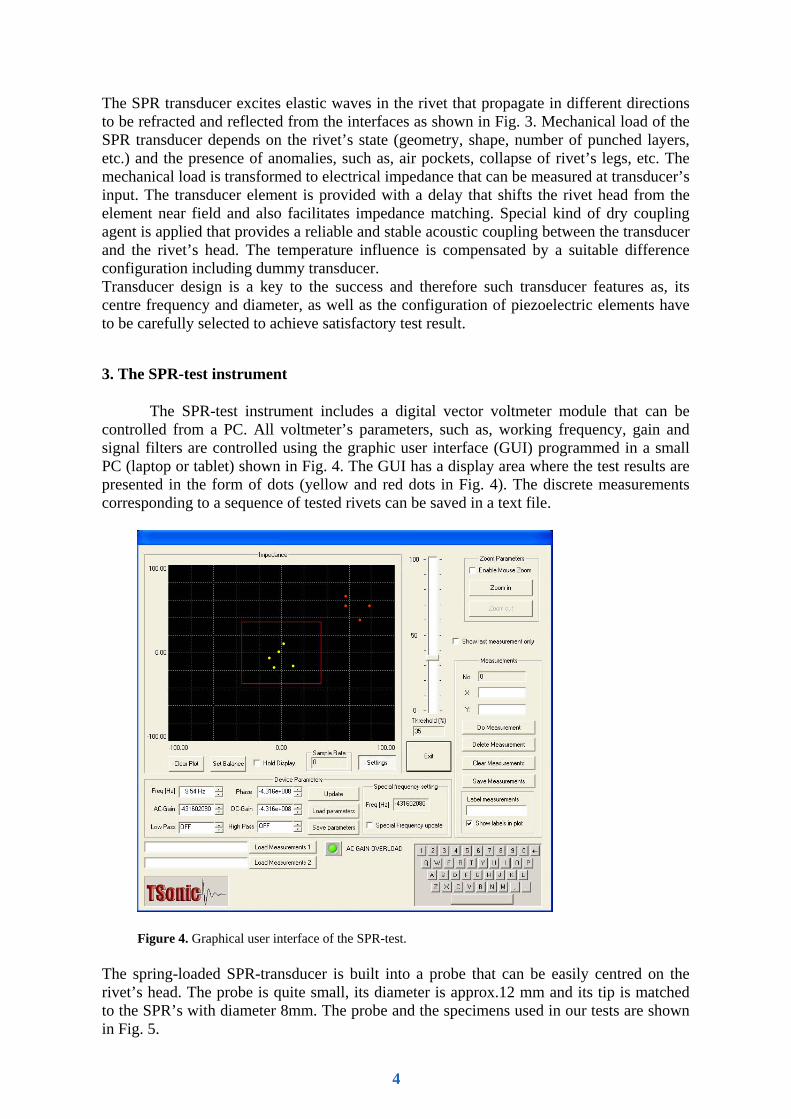
The SPR-test instrument includes a digital vector voltmeter module that can be controlled from a PC. All voltmeter’s parameters, such as, working frequency, gain and signal filters are controlled using the graphic user interface (GUI) programmed in a small PC (laptop or tablet) shown in Fig. 4. The GUI has a display area where the test results are presented in the form of dots (yellow and red dots in Fig. 4). The discrete measurements corresponding to a sequence of tested rivets can be saved in a text file.
••
•••
••
••
Figure 4. Graphical user interface of the SPR-test.
The spring-loaded SPR-transducer is built into a probe that can be easily centred on the rivet’s head. The probe is quite small, its diameter is approx.12 mm and its tip is matched to the SPR’s with diameter 8mm. The probe and the specimens used in our tests are shown in Fig. 5.
4

Figure 5. The SPR probe and the aluminium specimens used in our tests.
The SPR-test instrument in its current version is designed for manual tests of the SPR’s in a light weight car body.
4. Test results
Sensitivity of the SPR-test was verified using a number of specimens with known (labelled) rivets used for various material combinations, mainly aluminium alloys with different thickness.
SPR TEST INDICATIONS
-10 000
-8 000
-6 000
-4 000
-2 000
0
2 000
4 000
6 000
8 000
10 000
-35 000 -30 000 -25 000 -20 000 -15 000 -10 000 -5 000 0 5 000
Good 21Bad 21
Figure 6. An example of the SPR test result saved and presented in a spread sheet programme.
5
An example of such specimens is shown in Fig. 5 where two plates with 21 SPR’s in each, marked as “GOOD” and “BAD” are presented. The bad rivets were manufactured intentionally at the IARC’s laboratory using parameters outside the nominal range. One of the test results is shown in Fig. 6 where it can be seen that the good and bad rivets are properly clustered in the impedance plane.
5. Concluding remarks
We have presented a new ultrasonic technique applied to the NDT of self-piercing rivets used for spot joining of light weight bodies in automotive industry. The technique, referred to as the narrowband ultrasound spectroscopy, belongs to the class of ultrasound resonance methods that apply frequency domain analysis of the ultrasonic signals. A specially designed narrowband ultrasonic transducer connected to the SPR-test instrument is used for the inspection of self-piercing rivets. The instrument calculates the variations in the transducer’s electrical impedance and displays them as dots with given amplitudes and phases in the complex impedance plane. The difference between the impedance corresponding to the inspected rivet and the predetermined scatter of values corresponding to the sound rivets is monitored. The transducer, which is built into the spring loaded probe, is provided with dry coupling means. Laboratory tests have been performed that have confirmed the probe’s ability to detect some of the defects encountered in SPR’s.
References
[1] J. Mortimer, “Jaguar uses X350 car to pioneer use of self-piercing rivets”, Industrial Robot: An International Journal, vol. 28, no 3, 2001 pp. 192-198
[2] A. Migliori and J.L. Sarrao, Resonant Ultrasound Spectroscopy, John Wiley & Sons, Inc., 1997. [3] T. Stepinski and M. Jonsson, "Narrowband Ultrasonic Spectroscopy for NDE of Layered
Structures", INSIGHT, the Journal of The British Institute of Non-Destructive Testing, vol. 47, April, pp. 220 - 224, 2005.
[4] T. Stepinski and M. Engholm, "Narrowband Ultrasonic Spectroscopy for Inspecting Multilayered Aerospace Structures ", accepted for the 9th European Conference on NDT, September, 2006, Berlin.
6