Embed Size (px)
Citation preview

• Engineering 1182
College of Engineering
Engineering Education Innovation Center
Assembly Modeling Constraints
Rev: 20130715 AJP Assembly Modeling Constraints 1

• Engineering 1182
AssembliesAssemblies are collections of 3D
parts that form one engineering
system
1. Modeled to Fit Together
2. Location defined by 6 degrees
of freedom
• 3 translational (x,y,z)
• 3 rotational (about x,y,z axes)
3. Assembly Constraints• Concentric
• Mating Surfaces
• Coincident
• Distance
Rev: 20130715 AJP Assembly Modeling Constraints 2

• Engineering 1182
Modeled to
Work Together
• Compatible
Components
• Dimensional
constraints
• Assembly
Constraints
• Operational
Requirements
Rev: 20130715 AJP Assembly Modeling Constraints 3

• Engineering 1182
• 6 degrees of
freedom constrain
an instance of a
part file
• X,Y,Z Translation
• X,Y,Z Rotation
Defining
Location
Rev: 20130715 AJP Assembly Modeling Constraints 4

• Engineering 1182
• Concentric
• Mating Surfaces
• Coincident
• Distance
Assembly
Constraints
Rev: 20130715 AJP Assembly Modeling Constraints 5
The bridge example will be
used to demonstrate these
core concepts

• Engineering 1182
Concentric Constraints
Rev: 20130715 AJP Assembly Modeling Constraints 6
Axes of cylindrical features and
holes can be selected
Concentric constraints align
centerline axes
• Engineering 1182
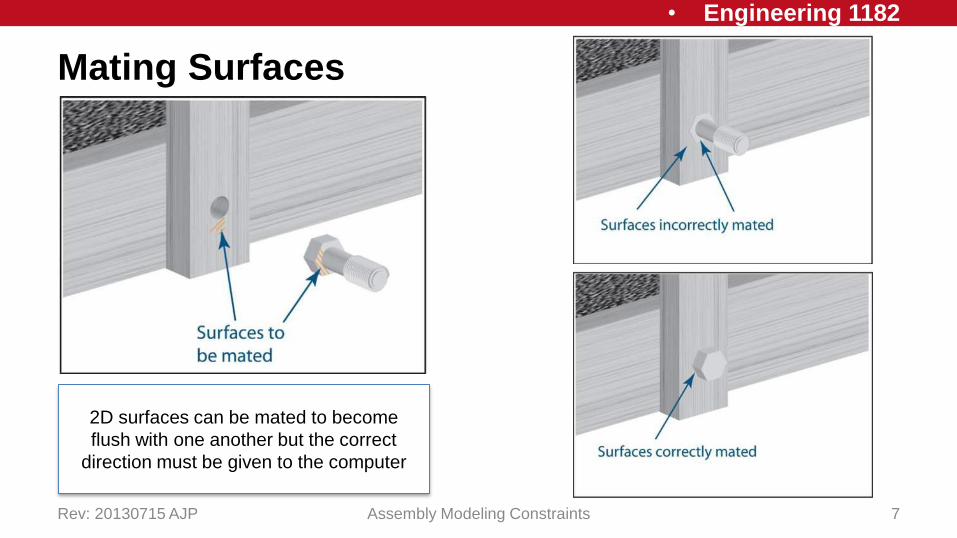
Mating Surfaces
Rev: 20130715 AJP Assembly Modeling Constraints 7
2D surfaces can be mated to become
flush with one another but the correct
direction must be given to the computer
• Engineering 1182
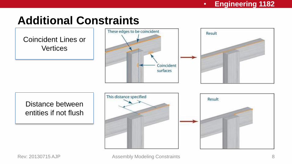
Additional Constraints
Rev: 20130715 AJP Assembly Modeling Constraints 8
Distance between
entities if not flush
Coincident Lines or
Vertices

• Engineering 1182
SolidWorks Adding Components
Rev: 20130715 AJP Assembly Modeling Constraints 9
In the Assembly tab (similar to
the Features tab of a Part file)
use the Insert Components
button to add part files to this
assembly
Select from the open
parts listed or use the
Browse to find saved
files
• Engineering 1182
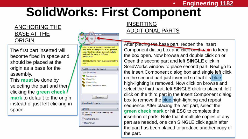
After placing the base part, reopen the Insert
Component dialog box and click on the pin to keep
the box open. Now browse and double click on or
Open the second part and left SINGLE click in
SolidWorks window to place second part. Next go to
the Insert Component dialog box and single left click
on the second part just inserted so that it’s blue
high-lighting is removed. Now click on browse and
select the third part, left SINGLE click to place it, left
click on the third part in the Insert Component dialog
box to remove the blue high-lighting and repeat
sequence. After placing the last part, select the
green check mark or hit ESC to complete the
insertion of parts. Note that if multiple copies of any
part are needed, one can SINGLE click again after
the part has been placed to produce another copy of
the part.
SolidWorks: First Component
The first part inserted will
become fixed in space and
should be placed at the
origin as a base for the
assembly.
This must be done by
selecting the part and then
clicking the green check
mark to default to the origin
instead of just left clicking in
space.
ANCHORING THE
BASE AT THE
ORIGIN
INSERTING
ADDITIONAL PARTS
• Engineering 1182
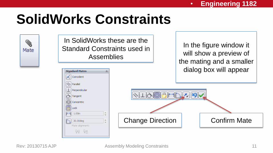
SolidWorks Constraints
Rev: 20130715 AJP Assembly Modeling Constraints 11
In SolidWorks these are the
Standard Constraints used in
Assemblies
In the figure window it
will show a preview of
the mating and a smaller
dialog box will appear
Change Direction Confirm Mate

• Engineering 1182
SolidWorks ExampleAssembly of a water
filtering pitcher
Rev: 20130715 AJP Assembly Modeling Constraints 12
• http://youtu.be/1s-
1CUoq1zE
• Engineering 1182
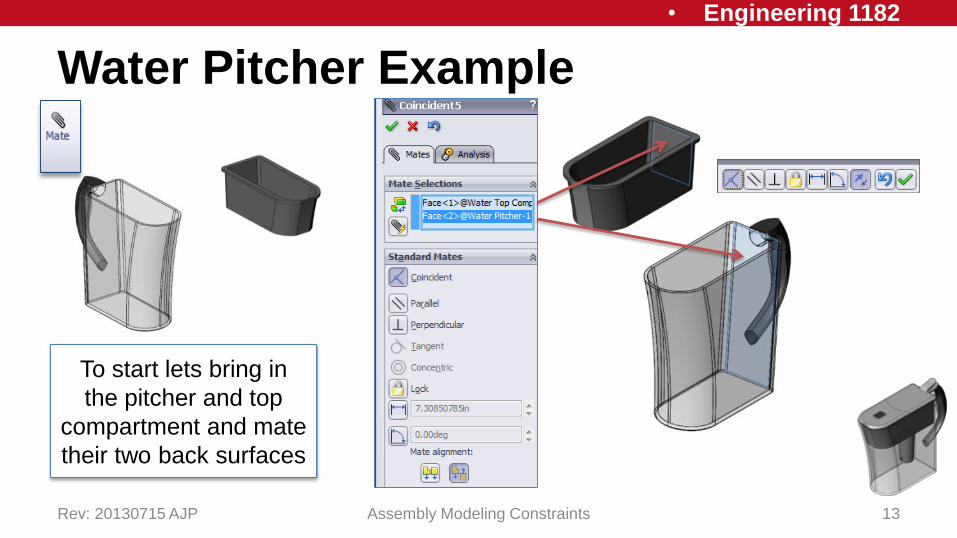
Water Pitcher Example
Rev: 20130715 AJP Assembly Modeling Constraints 13
To start lets bring in
the pitcher and top
compartment and mate
their two back surfaces

• Engineering 1182
Water Pitcher: Top Compartment
Rev: 20130715 AJP Assembly Modeling Constraints 14
Similar constraints are added to the
sides and top ridge in order to fully
constrain the top compartment

• Engineering 1182
Water Pitcher: Filter
Rev: 20130715 AJP Assembly Modeling Constraints 15
Now lets add to our
assembly the water
filter which fits into
the circular hole of
the top compartment
• Engineering 1182
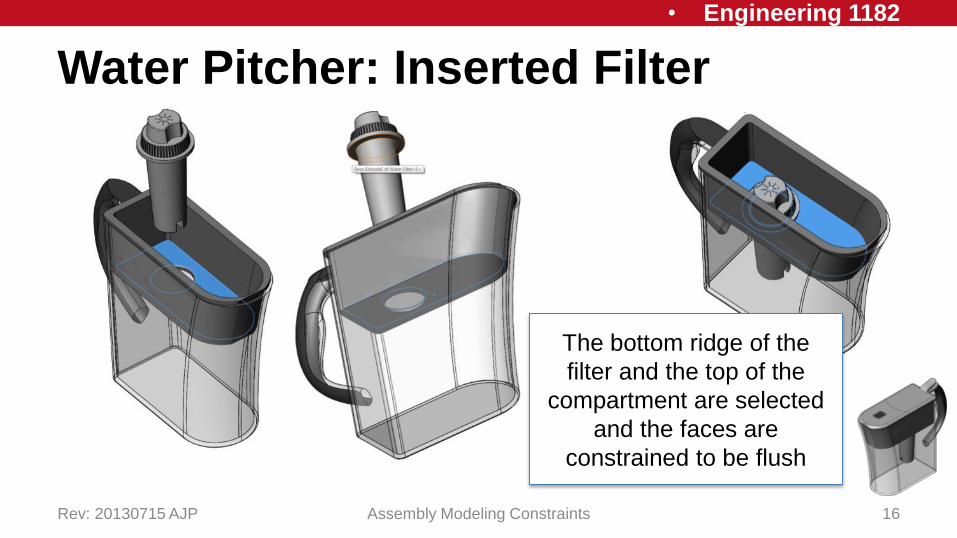
Water Pitcher: Inserted Filter
Rev: 20130715 AJP Assembly Modeling Constraints 16
The bottom ridge of the
filter and the top of the
compartment are selected
and the faces are
constrained to be flush

• Engineering 1182
Water Pitcher: Section View
Rev: 20130715 AJP Assembly Modeling Constraints 17
A section view can be used
in order to see that the
mates are correct
Choose the correct plane
that cuts through an object

• Engineering 1182
Water Pitcher: Sub-Assembly
Rev: 20130715 AJP Assembly Modeling Constraints 18
The top cover of the water
pitcher consists of 2 pieces
that were put together in a
separate assembly and
then brought into the
current assembly

• Engineering 1182
Deleting Constraints
Rev: 20130715 AJP Assembly Modeling Constraints 19
All Constraints applied
are located in the Model
Tree under Mates

• Engineering 1182
Deleting Constraints
Rev: 20130715 AJP Assembly Modeling Constraints 20
Constraints can be
selected and removed
using the delete key

• Engineering 1182
Assemblies Wrap-Up
• Assemblies – collection of 3D parts that form a system
• 6 Degrees of Freedom• XYZ Translation
• XYZ Rotation
• Assembly Constraints• Concentric
• Mating Surfaces
• Coincident
• Distance
Homework Assignment:Buck-Eye-Phone Assembly
Rev: 20130715 AJP Assembly Modeling Constraints 21

• Engineering 1182
In-Class Assignment
Rev: 20130715 AJP Assembly Modeling Constraints 22
Using the pre-made
blocks and wheels
construct a pinewood
derby racer using
assembly constraints
A starter assembly is
provided that is the basis for
the In Class exercise
Application Folder > IN-Class Problem Pinewood Derby Racer >
Starter Assembly > PINEWOOD RACER START ASSEMBLY