Embed Size (px)
Citation preview

ASSEMBLY MANUAL
TABLE OF CONTENTS
1- INTRODUCTION
1.1 THERMASTEELTM WALL PANELS1.2 Drawing and Element Numbers
2- ASSEMBLY
2.1 Sequence of Assembly2.2 Preparation of Foundation2.3 Wall Assembly2.4 Top Plates2.5 Setting the Wall2.6 “C” or Composite Openings for Doors, Windows, etc.
3- QUALITY CONTROL
3.1 Inspection of Panels3.2 On-Site Changes3.3 Dimensional Tolerances3.4 Erection of Panels
4- SAFETY
5- DRAWINGS

1. INTRODUCTION
1.1 The THERMASTEEL™ panel is a combination of expanded polystyrene core andgalvanized steel “C” channel studs. The panel has load bearing, sound transmission,thermal insulation, and vapor barrier characteristics. This manual outlines the propermethods for construction of buildings using the panel. In order to obtain the fulleffectiveness of the characteristics of the system, the directions found in this manualmust be observed.
1.2 Drawings and Element Numbers. Builders should study the appropriate drawingsbefore beginning construction and assembly. If shop drawings are provided byTHERMASTEEL™ they show an element number for each panel in the floor plan.This element number appears on the top end of each panel. Panel drawings areviewed from the exterior. Note that the exterior face of each panel has the logo (ifprovided) and leading edge overlap metal.
2. ASSEMBLY
2.1 Sequence of Assembly. Unload the container at the job site. Stack the panels for eachfloor so that they are in the necessary sequence for erection. Protect panels from highwinds and sharp impact. Panels are usually set starting at one corner of the buildingand proceeding in a counter-clockwise fashion.
2.2 Preparation of the Foundation. First verify that dimensions of the slab or subfloor arein accordance with contract documents and coordinate with shop drawings. Thesedimensions should be within the tolerances stipulated by the design professionaland/or by good construction practices. Locate conduit stub-ups (if any) and drillholes in base plate.
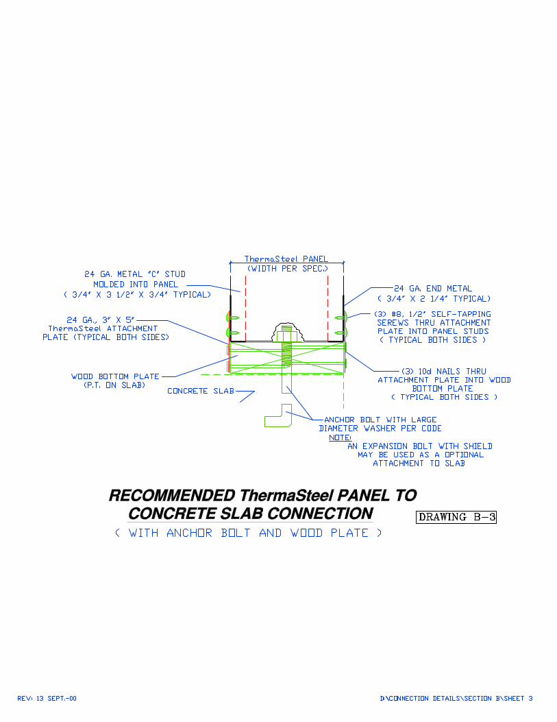
The panels are attached to the foundation using 2x wood plates or steel channel trackwith anchor bolts or powder shot pins. Steel track shall be set in a waterproof inhibitorsuch as roofing felt, foam tape, etc. Size and spacing of anchors shall be determinedby a design professional based on building code requirements.
Caulk and set baseplates or track to building dimensions and secure to the slab orsubfloor using anchors as per the design drawings. Be sure the plates are level and thecorners are square. If the foundation is not level, shim and grout with cement to obtaina level baseplate (track). Do NOT try to obtain a level wall by shimming the panels.
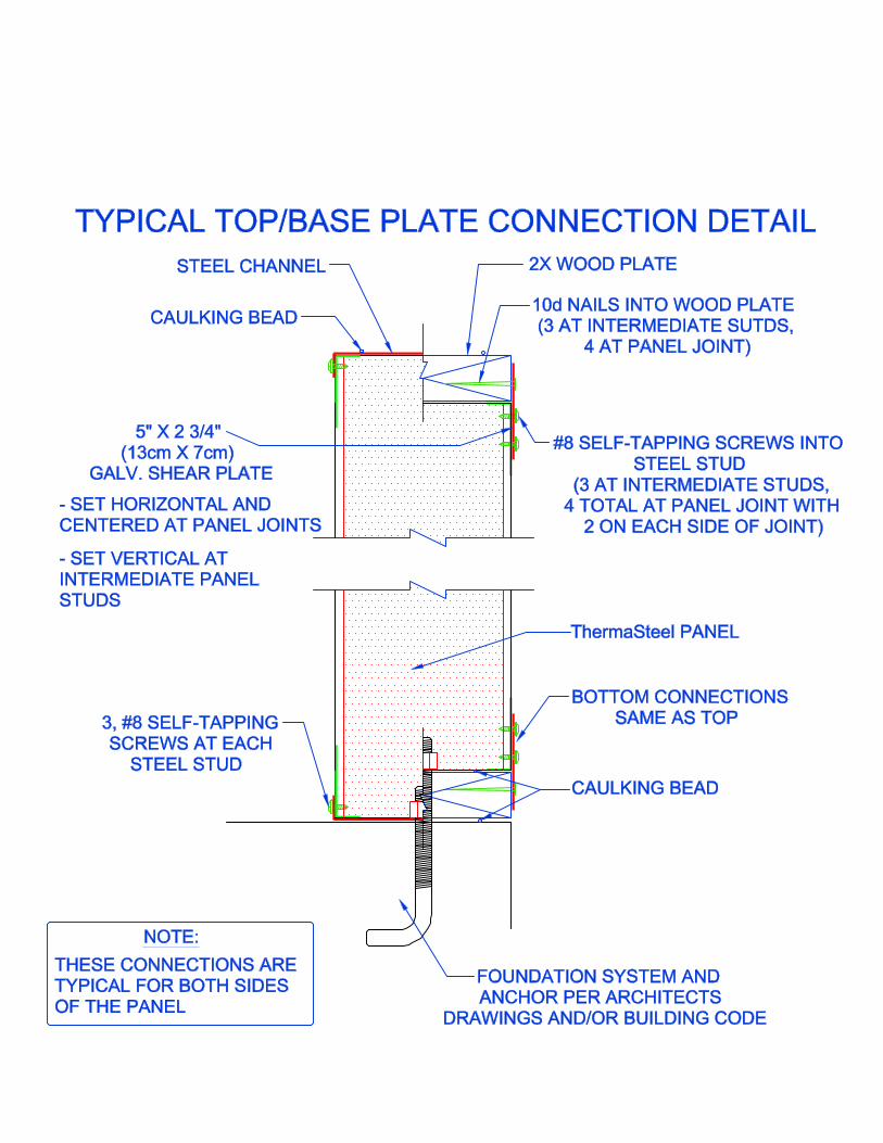
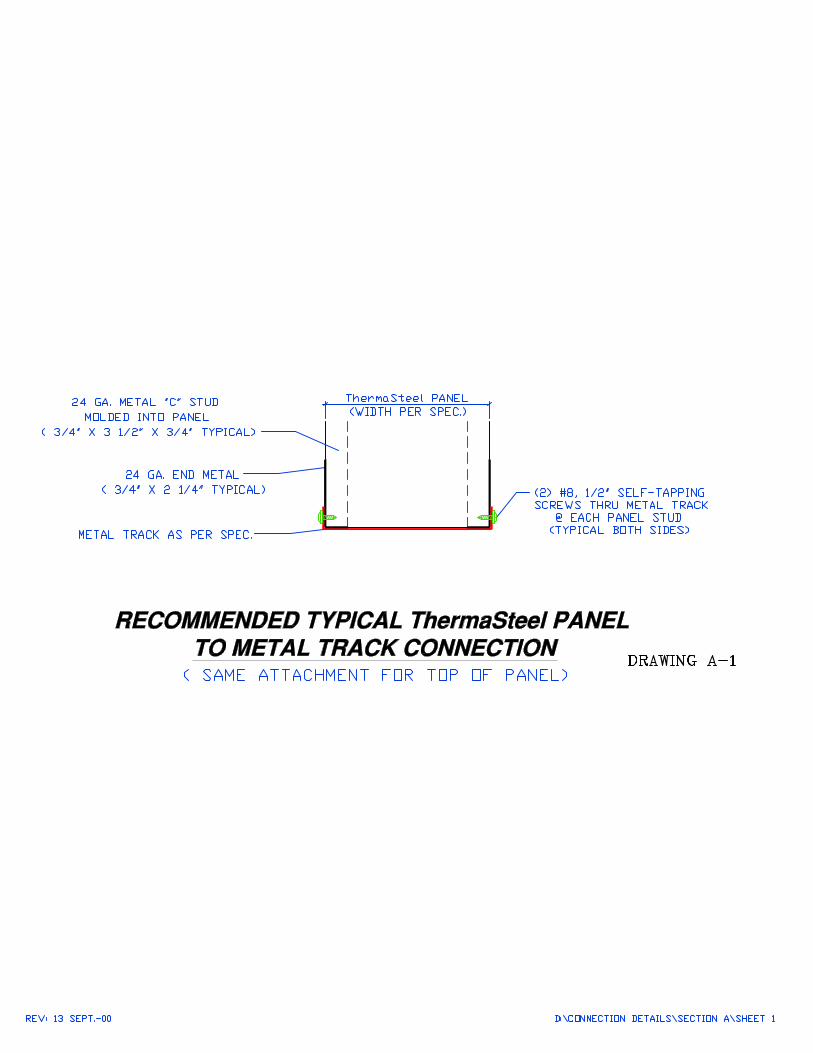
Once the bottom baseplates (track) are set and level, verify each panel dimensionalong the baseplate. Nail or screw attachment plates to both sides of baseplates asshown in Detail 1. Locate the attachment plates to fall at each panel joint and eachsteel stud in the panel.
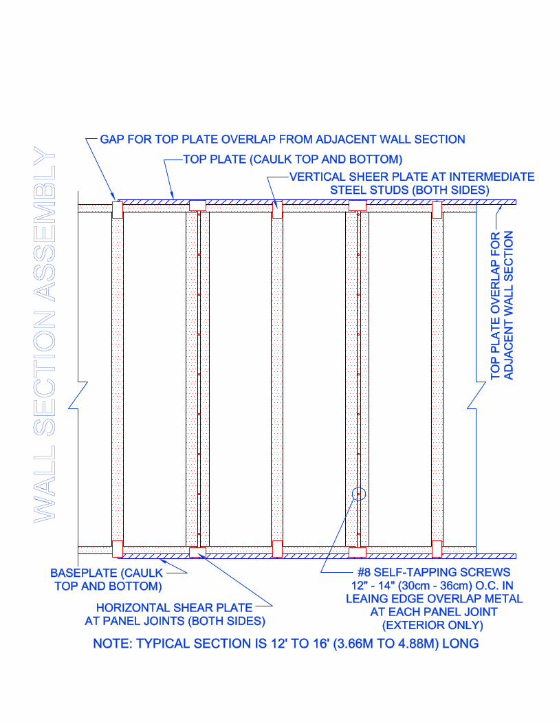
2.3 Wall Assembly. The usual method of assembly is to pre-assemble wall sections andset them in place. Sections are usually pre-assembled in 12 ft. to 16-ft. sections. Alevel work area at least 16 ft. x 12 ft. is required. This area should be cleared ofdebris and a base line marked at the bottom and left hand side of the assembly area.The marked lines must be true and square to avoid mis-alignment of the panels.
Once the assembly area is cleared and marked, consult the floor plan and determinewhich sections are to be assembled and in what sequence. Using the element numbersas reference, obtain the necessary panels and lay them out with the interior facedown. Caulk joints (if specified) and push the shiplaps together (Note: Each lap jointcan be gaped open up to 1/4” as needed to adjust for discrepancies in wall length).Check the section for overall dimensions and for squareness. Once satisfied with thealignment, screw the panels together through the leading overlap edge metal asshown in Detail 2. Locate conduit stub-ups (if any) on panel and drill up from panelbottom (also, mark location on subfloor).
2.4 Top Plates. Tie Sections together using 2x wood top plates or c-channel steel toptrack (See specs). Cut the top plate or track on site to allow overlap to the center ofthe next panel section steel stud at 16” or 24”. Fasten attachment plates to the topplate or track so that the attachment plates will fall at each panel joint and verticalsteel stud in the panel. Drill the top plate or track to match conduit or wiring chaselocations, if any, in the assembled section before attaching the plate or track to thepanels. Caulk the 2x plate or track (or panel end) and attach the top plate to the wallsection by placing a screw in the ends and middle section attachment plates. Thisconnection is temporary and is used only to keep the top plate in place duringerection of the walls. The top plate is permanently secured to the wall sections afterthe floor or roof system has been set, which loads the wall.
In cutting the top plates or track, observe the following guidelines.
• Where a wall section joins another wall section, overlap the top plate ortrack to the next section center of steel stud at 16” (or 24”) as shown inDetail 2.
• Where a wall section joins a corner, the section top plate should overlaponto the corner to the full width of the corner on one side and width of thecorner less the wall thickness on the other side.
• Where a wall section butts into another wall section, overlap the top platethe full thickness of the butt wall.
• Gap between adjacent top plates (cutting error) shall not exceed 1/2”.• Stagger top plate joints so that the joint does not fall directly over a panel
joint, but does fall over the center of an inner steel stud.
2.5 Setting the Wall. Caulk the top of the baseplate (or track) and raise the assembledwall section into place. Connect the panels to the baseplate as shown in Detail 1 and2. Attach the overlapping top plates (or track) to each other as shown in Detail 1 and2. Temporarily brace the top of the wall to the ground or floor so it stands true andplumb.
2.6 “C” or Composite Openings for Doors, Windows, Etc. Some panel openings areassemblies consisting of 2 or more components. These are shipped disassembled andmust be assembled on site. Refer to the data sheets provided and assemble thesesections before setting them in place. As in all assemblies, carefully check the unitfor overall dimensions and squareness before setting it into wall section.
3. QUALITY CONTROL
3.1 Inspection of Panels. Panels have been checked for density and fusion quality and fordimensions before shipment, but should be checked for damage and spot-checked fordimensions as they are unloaded and stacked. For dimensional tolerances refer to 3.3.As a general rule, any defect in the polystyrene core of the panel such as small cuts ornicks will not affect the integrity of the panel. Damage to the metal will affect thepanel’s strength and integrity and can result in a rejected panel; refer to 3.2 below.
3.2 On-Site Changes. in general, any changes deemed necessary on-site must be clearedwith the manufacturer before the changes are made. The following site changes maybe made.
• Reject any panel with vertical steel members that have any buckles or dents. Thepanel can be salvaged by cutting out the damaged section and inserting a wood ormetal building stud. Fill gaps with insulation.
• Bends may be straightened in the horizontal metal at the top and bottom edges ofthe panel.
• Straighten any bends or dents in the leading edge overlap metal.• Electrical Boxes. Use a hot knife or other acceptable cutting tool. Do not exceed the
box dimensions and, where possible, locate the box beside a vertical steel channelfor screw attachment. Boxes should have recessed “ears” or brackets behind thewall cladding.
• Wiring or Conduit Chases. If chases provided are not used, vertical chases may becut in to the polystyrene with a hot knife or other acceptable cutting tool. Verticalchases shall be cut a minimum of 2” from any vertical steel channel. Do not exceedhalf the panel thickness in depth or 1” in width when making these cuts. Horizontalchase cuts may be extended behind the vertical metal by drilling with a 1” bit nearmid-depth of the panel.
3.3 Dimensional Tolerances.
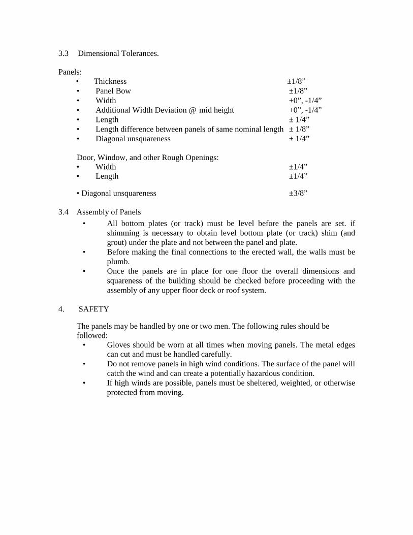
Panels:• Thickness ±1/8”• Panel Bow ±1/8”• Width +0”, -1/4”• Additional Width Deviation @ mid height +0”, -1/4”• Length ± 1/4”• Length difference between panels of same nominal length ± 1/8”• Diagonal unsquareness ± 1/4”
Door, Window, and other Rough Openings:• Width ±1/4”• Length ±1/4”
• Diagonal unsquareness ±3/8”
3.4 Assembly of Panels• All bottom plates (or track) must be level before the panels are set. if
shimming is necessary to obtain level bottom plate (or track) shim (andgrout) under the plate and not between the panel and plate.
• Before making the final connections to the erected wall, the walls must beplumb.
• Once the panels are in place for one floor the overall dimensions andsquareness of the building should be checked before proceeding with theassembly of any upper floor deck or roof system.
4. SAFETY
The panels may be handled by one or two men. The following rules should befollowed:
• Gloves should be worn at all times when moving panels. The metal edgescan cut and must be handled carefully.
• Do not remove panels in high wind conditions. The surface of the panel willcatch the wind and can create a potentially hazardous condition.
• If high winds are possible, panels must be sheltered, weighted, or otherwiseprotected from moving.
CONNECTION DETAILS
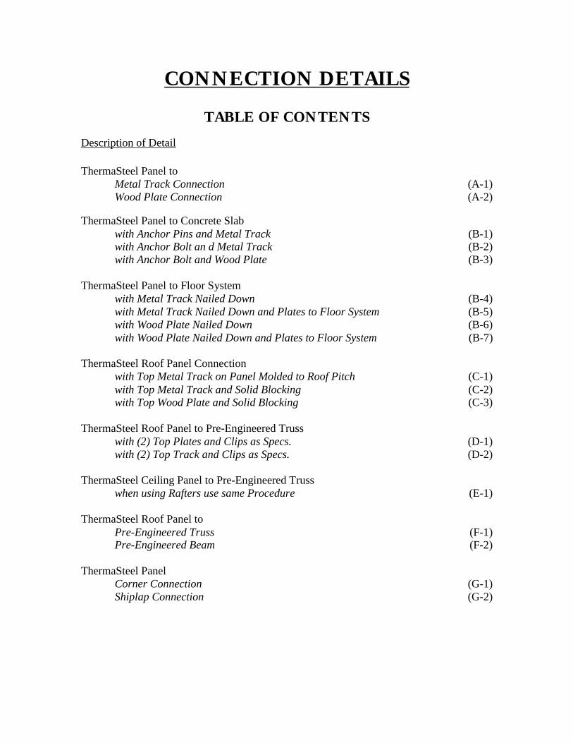
TABLE OF CONTENTSDescription of Detail
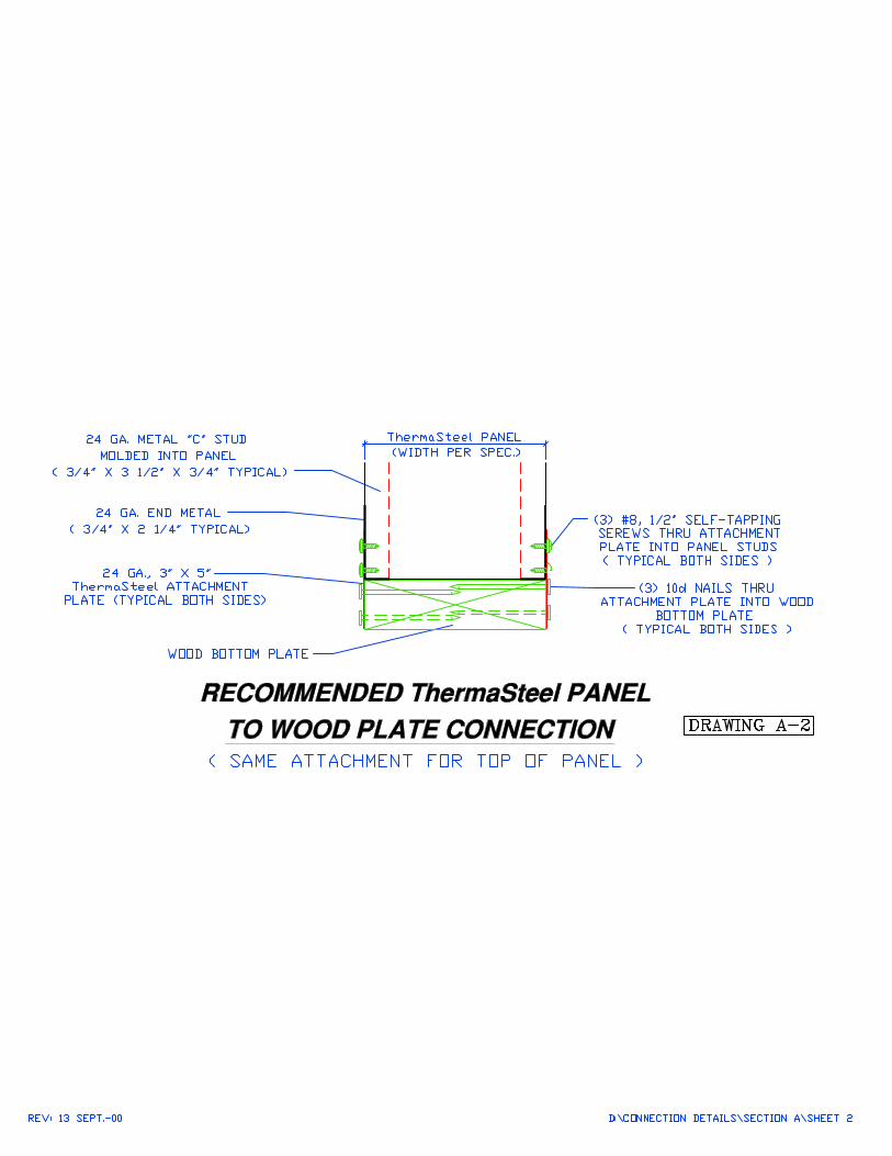
ThermaSteel Panel toMetal Track Connection (A-1)Wood Plate Connection (A-2)
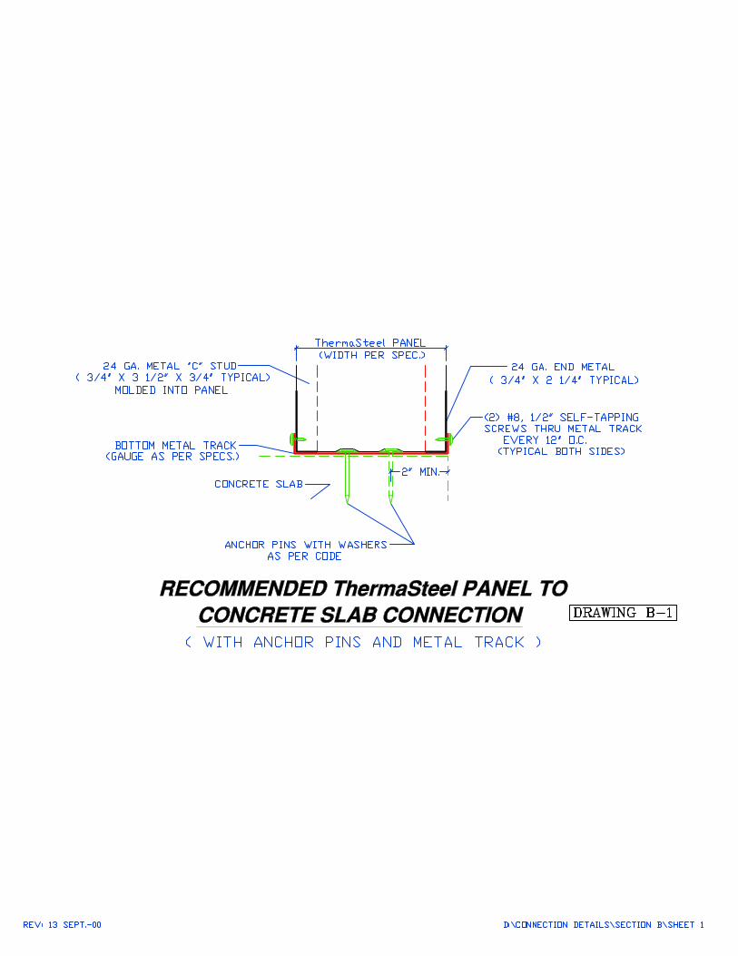
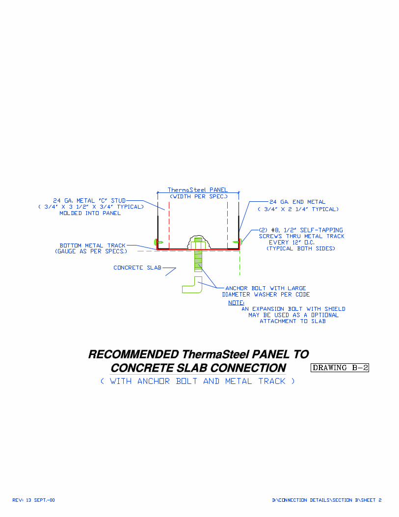
ThermaSteel Panel to Concrete Slabwith Anchor Pins and Metal Track (B-1)with Anchor Bolt an d Metal Track (B-2)with Anchor Bolt and Wood Plate (B-3)
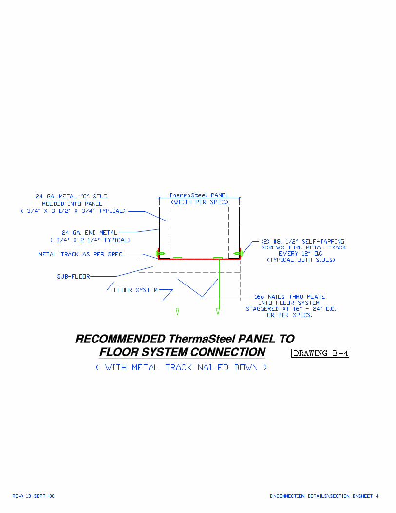
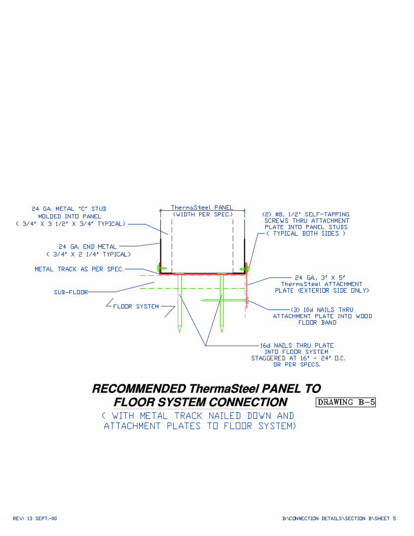
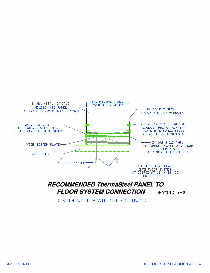
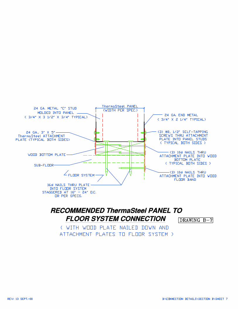
ThermaSteel Panel to Floor Systemwith Metal Track Nailed Down (B-4)with Metal Track Nailed Down and Plates to Floor System (B-5)with Wood Plate Nailed Down (B-6)with Wood Plate Nailed Down and Plates to Floor System (B-7)
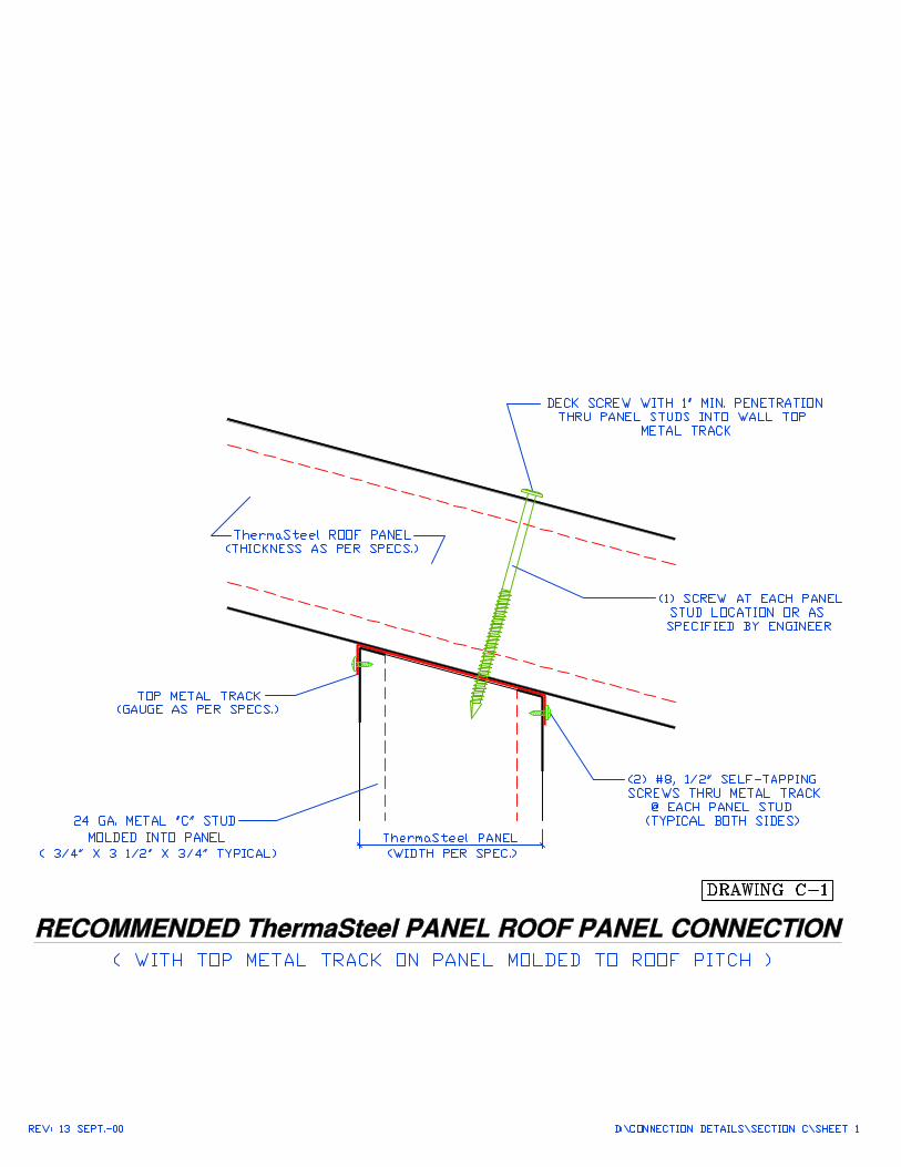
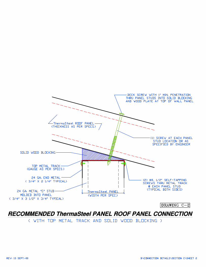
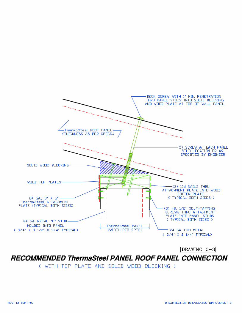
ThermaSteel Roof Panel Connectionwith Top Metal Track on Panel Molded to Roof Pitch (C-1)with Top Metal Track and Solid Blocking (C-2)with Top Wood Plate and Solid Blocking (C-3)
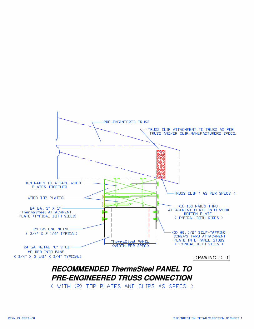
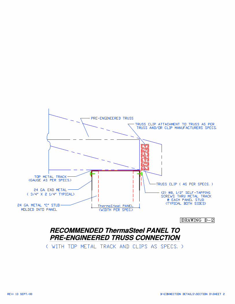
ThermaSteel Roof Panel to Pre-Engineered Trusswith (2) Top Plates and Clips as Specs. (D-1)with (2) Top Track and Clips as Specs. (D-2)
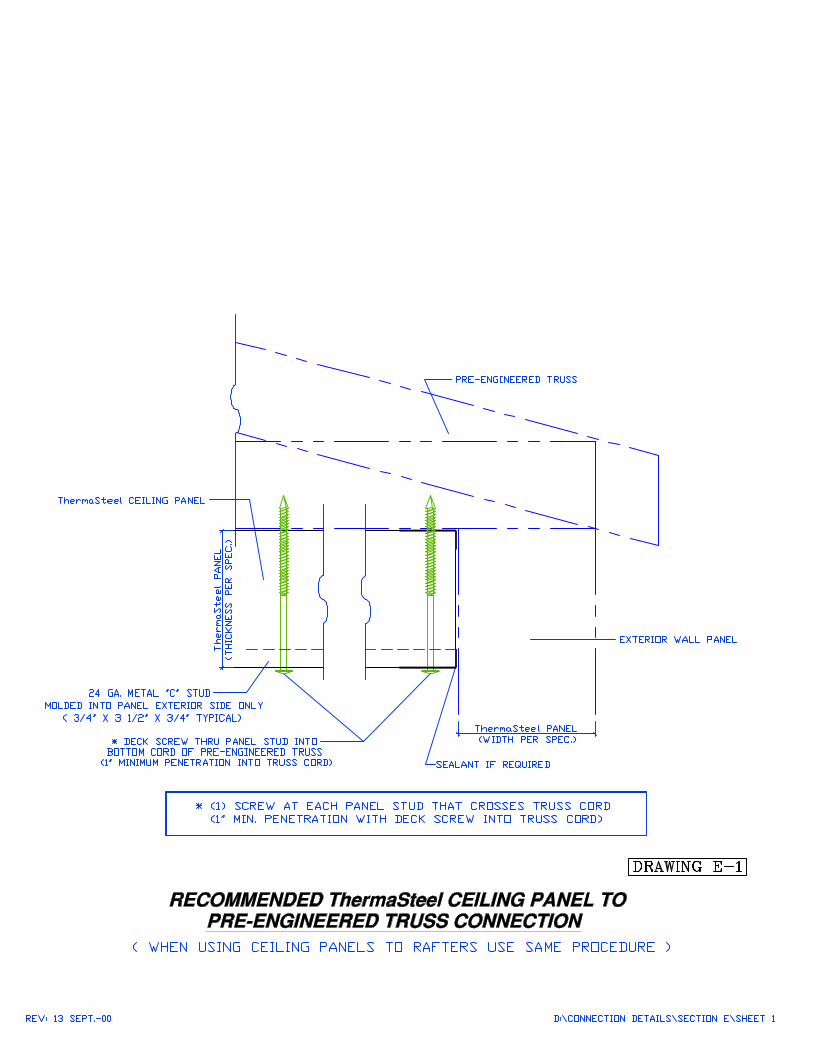
ThermaSteel Ceiling Panel to Pre-Engineered Truss when using Rafters use same Procedure (E-1)
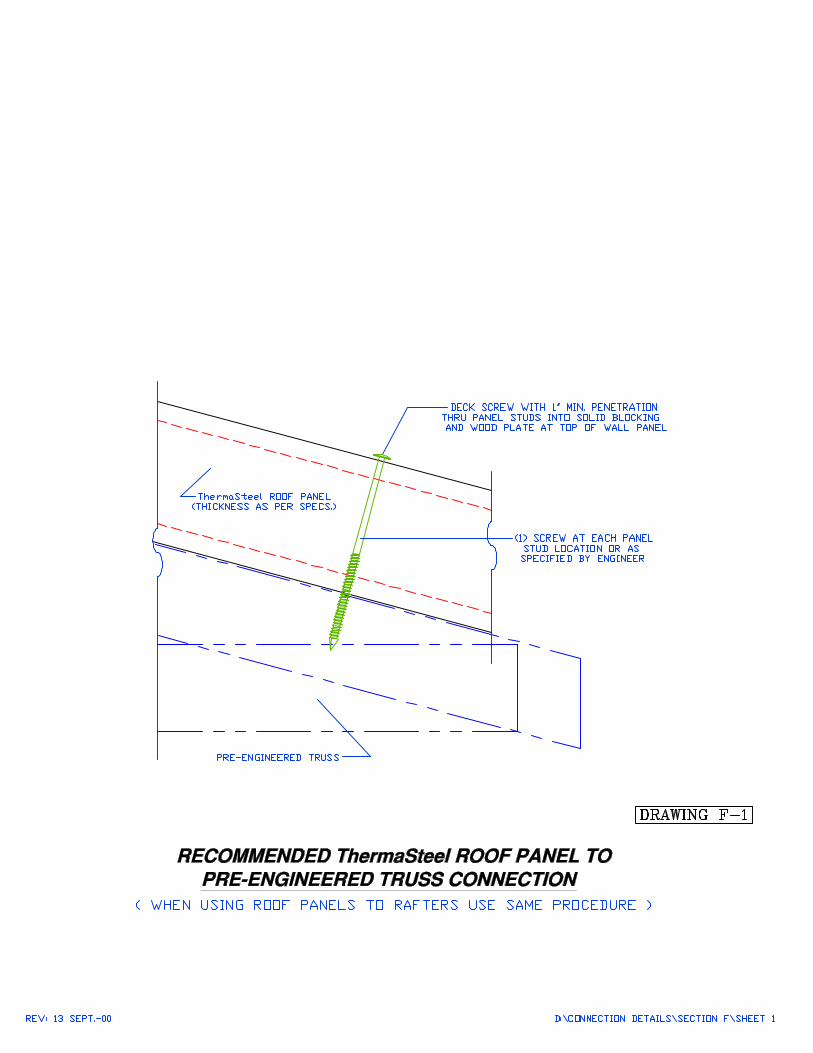
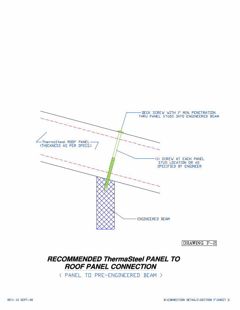
ThermaSteel Roof Panel toPre-Engineered Truss (F-1)Pre-Engineered Beam (F-2)
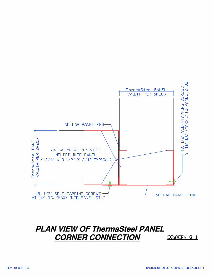
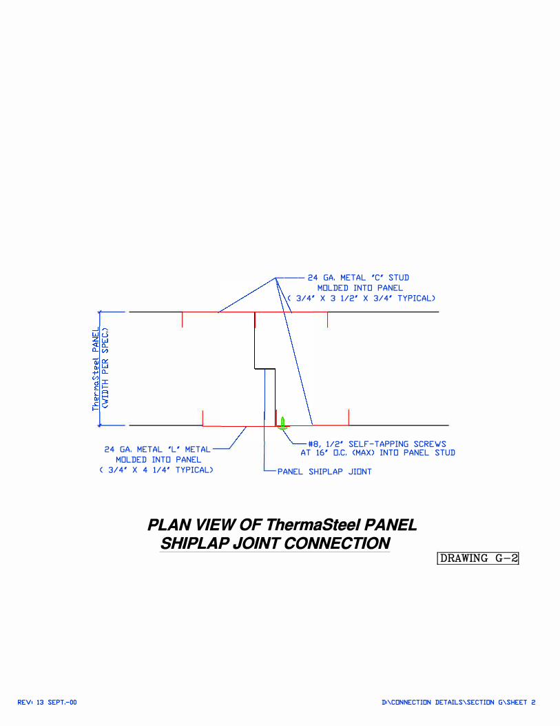
ThermaSteel PanelCorner Connection (G-1)Shiplap Connection (G-2)
REV• 13 SEPT.-00
24 GA. MET AL 'L' MET AL
MOLDED INTO PANEL
< 3/4' X 4 1/4' TYPICAL>
,......--- 24 GA. MET AL 'C' STUD
MOLDED INTO PANEL
< 3/4' X 3 1/2' X 3/4' TYPICAL>
#8, 1/2' SELF-TAPPING SCRE'w'S
AT 16' O.C. <MAX) INTO PANEL STUD
PANEL SHIPLAP JIDNT
PLAN VIEW OF ThermaSteel PANEL
SHIPLAPJOINTCONNECnON !DRAWING G-2!
D•\CDNNECTIDN DETAILS\SECTIDN G\SHEET 2