Embed Size (px)
Citation preview

ASIC 120: Digital Systems and Standard-Cell ASIC Design
Tutorial 1: Introduction to Digital Circuits
October 11, 2005

Outline
• Digital Systems
• Combinational Logic– NOT, AND, OR, XOR, NAND, etc.– mux, half-adder, full-adder
• Sequential Logic– flip-flop/register, shift register, counter– state machines

Digital Systems
• Analog vs. Digital– continuously varying vs. discrete– imprecise vs. precise– 0..1 vs. 0 or 1
• Digital systems excel at…– repetitive calculations– large amounts of data– reproducible results

The Big Picture

The Big Picture
FreescalePowerPC
microprocessor(PPC)
MPC850 family
RAMXilinx
Spartan-IIXC2S30FPGA
AlteraPLD
Ethernet Connector

Combinational and Sequential Logic
• We can break a digital system into two types of logic
• Combinational– computation happens
in a linear fashion
• Sequential– computation involves a
feedback loop (memory)
In Out
Combinational
Input Output
In Out
Combinational
Input Output
Feedback

Combinational Logic: NOT
A X
0 1
1 0
Input Output
Truth Table

Combinational Logic: AND
A B X
0 0 0
0 1 0
1 0 0
1 1 1

Combinational Logic: OR
A B X
0 0 0
0 1 1
1 0 1
1 1 1

Combinational Logic: XOR
A B X
0 0 0
0 1 1
1 0 1
1 1 0

Combinational Logic: NAND
A B X
0 0 1
0 1 1
1 0 1
1 1 0

Combinational Logic: NOR, XNOR
A B X
0 0 1
0 1 0
1 0 0
1 1 0
A B X
0 0 1
0 1 0
1 0 0
1 1 1
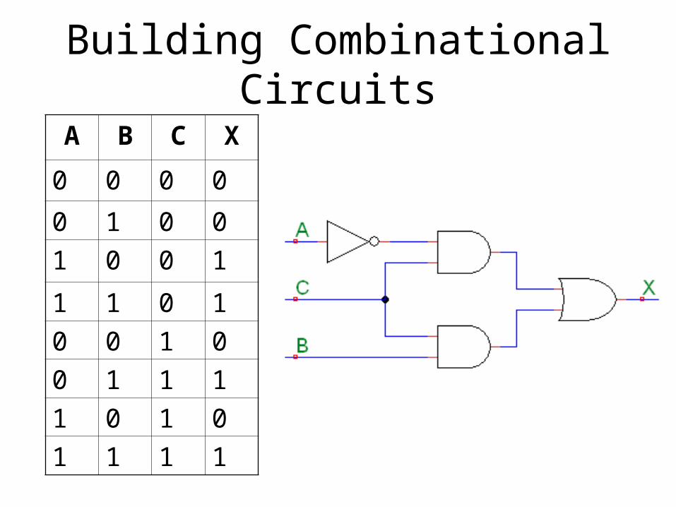
Building Combinational Circuits
A B C X
0 0 0 0
0 1 0 0
1 0 0 1
1 1 0 1
0 0 1 0
0 1 1 1
1 0 1 0
1 1 1 1

Combinational Logic: MUX(multiplexer)
A B C X
0 0 0 0
0 1 0 0
1 0 0 1
1 1 0 1
0 0 1 0
0 1 1 1
1 0 1 0
1 1 1 1

Half Adder
A B S C
0 0 0 0
0 1 1 0
1 0 1 0
1 1 0 1

Full Adder

Full Adder

What I’ve Skipped
• Gates with more than two inputs• Boolean algebra• Karnaugh maps• Quine-McCluskey method• Binary arithmetic, base conversions• Practical digital circuits have more than 0s
and 1s• Transmission gates, tri-state buffers

Sequential Logic
In Out
Combinational
Input Output
In Out
Combinational
Input Output
Feedback

Basic Feedback Element: SR latch
S R Q Qnext
0 0 0 0
0 0 1 1
0 1 0 0
0 1 1 0
1 0 0 1
1 0 1 1
1 1 0 N/A
1 1 1 N/A

D Flip-Flop or Register
D Clk Q Qnext
0 0 0 0
0 0 1 1
1 0 0 0
1 0 1 1
0 01 0 0
0 01 1 0
1 01 0 1
1 01 1 1

Synchronous vs. Asynchronous
• Synchronous– circuit operation governed by a clock– currently more popular and practical
• Asynchronous– circuit operation independent of a clock– potentially faster than synchronous– lower power consumption– difficult to design

Sequential Constructs
• Shift register
• Counter
• State Machines

State Machines
• Useful abstract constructs for more complex sequential logic

What I’ve Skipped
• Other flip-flops (RS, T, JK)
• Other interesting sequential circuits (barrel shifters, etc.)

Hardware Description Languages (HDLs)
• HDL describes in text a digital circuit
• Examples– VHDL (we will look at this next time)– Verilog– AHDL– JHDL

Hardware Description Languages (HDLs)
• schematics are useful for…– drawing high level diagrams– manually working out simple pieces of logic
• HDLs are useful for…– describing complex digital systems
• HDLs are not...– software programming languages (C, Java,
assembly, etc.)

Summary
• Digital Systems
• Combinational Logic– NOT, AND, OR, XOR, NAND, etc.– mux, half-adder, full-adder
• Sequential Logic– flip-flop/register, shift register, counter– state machines

UW ASIC Design Team
• www.asic.uwaterloo.ca• reference material
– Bryce Leung’s tutorials (UW ASIC website)– Michael Goldsmith’s tutorials (UW ASIC
website)– your course notes
• my contact info:Jeff Wentworth,