Embed Size (px)
Citation preview
ARTICLES
PLASMA DETACHMENT INJET MARK I DIVERTOR EXPERIMENTS
A. LOARTE∗, R.D. MONK, J.R. MARTIN-SOLISa, D.J. CAMPBELL∗, A.V. CHANKINb,S. CLEMENT, S.J. DAVIES, J. EHRENBERG, S.K. ERENTSc, H.Y. GUO,P.J. HARBOUR, L.D. HORTON, L.C. INGESSON, H. JACKEL, J. LINGERTAT,C.G. LOWRY, C.F. MAGGI, G.F. MATTHEWS, K. McCORMICKd, D.P. O’BRIEN,R. REICHLE, G. SAIBENE, R.J. SMITH, M.F. STAMP, D. STORK, G.C. VLASESJET Joint Undertaking, Abingdon, Oxfordshire, United Kingdom
a Escuela Politecnica Superior, Universidad Carlos III de Madrid, Spainb Russian Research Centre, Kurchatov Institute, Moscow, Russian Federationc UKAEA, Culham Laboratory, Abingdon, Oxfordshire, United Kingdomd Max-Planck-Institut fur Plasmaphysik, Garching, Germany
ABSTRACT. The experimental characteristics of divertor detachment in the JET tokamak
with the Mark I pumped divertor are presented for ohmic, L mode and ELMy H mode experi-
ments with the main emphasis on discharges with deuterium fuelling only. The range over which
divertor detachment is observed for the various regimes, as well as the influence of divertor config-
uration, direction of the toroidal field, divertor target material and active pumping on detachment,
will be described. The observed detachment characteristics, such as the existence of a considerable
electron pressure drop along the field lines in the scrape-off layer (SOL), and the compatibility of
the decrease in plasma flux to the divertor plate with the observed increase of neutral pressure
and Dα emission from the divertor region, will be examined in the light of existing results from
analytical and numerical models for plasma detachment. Finally, a method to evaluate the degree
of detachment and the window of detachment is proposed, and all the observations of the JET
Mark I divertor experiments are summarized in the light of this new quantitative definition of divertor
detachment.
1. INTRODUCTION
In recent years it has become evident that theproblems of power deposition and wall erosion are ofparamount interest in the development of next steptokamak devices, such as ITER. While the high recy-cling divertor regime may be a marginally accept-able regime of operation from the viewpoint of powerhandling, the erosion associated with the large inci-dent ion fluxes may seriously limit the lifetime ofthe divertor target, making the applicability of thehigh recycling divertor questionable for next stepdevices [1]. Furthermore, if the high recycling regimeis extrapolated to some of the operating modes pro-posed for ITER, even the power deposited onto thedivertor by the ions and electrons recombining inthe material surface will exceed the steady statepower handling capability of the divertor target [2].As a solution to these two problems, the so-called‘detached’ divertor regime was first proposed as thepreferred divertor regime of a next step device [3].
∗ Present affiliation: The NET Team, Max-Planck-
Institut fur Plasmaphysik, Garching, Germany.
The basic physical features of the detached diver-tor rely upon the transfer of parallel momentum fromthe plasma to the recycling neutral atoms and subse-quently to the divertor target and vessel walls. Thishas two important effects: the plasma pressure at thedivertor is reduced with respect to that expected fromthe high recycling regime; and, together with ioniza-tion losses and impurity radiation, it leads to low elec-tron temperatures at the divertor that allow volumerecombination processes to take place. The combina-tion of pressure reduction and hydrogen recombina-tion leads to lower incident ion fluxes to the diver-tor target and potentially allows the achievementof higher radiative power fractions in the scrape-offlayer (SOL) and divertor. This comes about becausethe recombination power deposited on the targetdecreases with the reduction of the plasma flux [4].A further beneficial effect of the detached divertorregime is that the largest particle flux impingingon the surfaces is in the form of hydrogenic neutralatoms and molecules scattered from the plasma thatare not accelerated by the sheath potential and hencehave lower energies than the corresponding ions. This
NUCLEAR FUSION, Vol. 38, No. 3 (1998) 331

A. LOARTE et al.
minimizes the amount of physical sputtering sufferedby the divertor target.
A regime that displays most of the characteristicsdescribed above has been obtained in many diver-tor experiments by increasing the main plasma den-sity via deuterium (or hydrogen) fuelling at constantinput power [5–12]. The basic features reported pre-viously from JET experiments during the 1990/91experimental campaign [5, 7] have been confirmed inthe experiments carried out in JET with the Mark Ipumped divertor but with a much improved diagnos-tic capability, which has allowed a quantitative char-acterization of this regime.
The divertor configuration is obtained in the JETMark I pumped divertor by using the four diver-tor coils at the bottom of the vacuum vessel. Thedivertor target is situated on top of these coils andconsists of rows of tiles (made of carbon (CFC) orberyllium) with toroidal gaps that allow an efficientdivertor pumping by means of the divertor cryopump.For further details of the JET Mark I pumped diver-tor hardware and a summary of the experimentalresults the reader is referred to Refs [13, 14].
Dedicated experiments have been carried out dur-ing the JET Mark I pumped divertor 1994/95 exper-imental campaign to study the detached divertorregime. In this article, we report upon the detailedanalysis of measurements obtained during theseexperiments and interpret them in the light of exist-ing results from one dimensional (1-D) SOL analyt-ical/numerical models and 2-D SOL computer codesfor the plasma edge. In Section 2, we describe theexperiments performed in JET together with theavailable diagnostic information. In Section 3, we con-centrate on a detailed description of the evolution ofthe main plasma, SOL and divertor plasma param-eters for a few selected discharges in different con-finement regimes as the fuelling is increased, caus-ing the divertor to change from low to high recyclingand ultimately access the detached regime. In Sec-tion 4, we describe the influence of additional fac-tors on the detached divertor regime such as diver-tor geometry, wall clearance, divertor pumping andthe effect on detachment of the toroidal field direc-tion. In Section 5, we concentrate on the behaviour ofimpurities during divertor detachment, including theeffect of different divertor target materials. In Sec-tion 6, we define and quantify the degree of detach-ment by extrapolation of experimental scaling lawsfor the high recycling regime and summarize theresults of the JET Mark I detached divertor exper-iments in this new context. We use the new defi-
nition to illustrate concepts such as partial detach-ment and the window of tokamak operation in termsof the main plasma density over which the detacheddivertor regime exists (detachment window). Finally,in Section 7 we summarize the findings of thisarticle.
2. DIAGNOSTICS ANDEXPERIMENTAL METHOD
2.1. Diagnostic systems
The range of diagnostics used to characterize themain plasma, SOL and divertor plasma has beenvery extensive in the JET Mark I pumped divertor1994/95 experimental campaign. In addition to theroutine diagnostics for the main plasma that providemeasurements of density, electron and ion temper-ature, bulk plasma radiation and concentrations ofimpurities, the following diagnostics have been oper-ated in the experiments described in this article tocharacterize the plasma and hydrogenic neutrals inthe main SOL and divertor region:
(a) Main plasma edge and SOL diagnostics:
• Reciprocating Langmuir probe. This provides pro-files of electron density and temperature in the mainSOL.• Main chamber visible spectroscopy. This providesinformation on the influxes of deuterium and impu-rities that enter the plasma from the main chamberwalls.• Edge electron cyclotron emission (ECE) heterodyneradiometer. This provides electron temperature pro-files in the outer regions of the main plasma.
(b) Divertor diagnostics:
• Divertor target Langmuir probes. These providedetailed information on the ion flux, electron den-sity and temperature profiles at the divertor target.With the use of 4 Hz strike point sweeping, the radialresolution of these profiles approaches 2 mm at thedivertor, limited only by the width of the probe tips.• Divertor microwave diagnostics. These provideinformation on the line integrated and peak electrondensity across the inner or outer divertor leg.• Divertor infrared thermography. This provides thepower deposition profiles on the divertor target.Owing to the large radiated power fraction duringdetachment, the power arriving at the divertor isusually very low and under the detection limit of
332 NUCLEAR FUSION, Vol. 38, No. 3 (1998)

ARTICLE PLASMA DETACHMENT IN JET
FIG. 1. (a) Lines of sight of the divertor microwave diagnostics and the main
chamber interferometer. (b) Lines of sight of the various bolometer cameras in
JET used to calculate the radiation emissivity profiles by tomographic recon-
struction. (c) Lines of sight of the various diagnostics used in this article, such
as visible spectroscopy, VUV divertor spectroscopy and thermal helium beam.
(d) Spatial location of the divertor Langmuir probes, reciprocating probe and
divertor pressure gauges. A typical MHD equilibrium used in the experiments
described in the article is shown for comparison.
the JET diagnostic. However, this diagnostic can beused with a different purpose for detached divertorexperiments, in which very high electron densities(ne ≈ 1020–1021 m−3) and low electron tempera-tures (Te ≤ 5 eV) are observed in the divertor region.The bremsstrahlung emission of such a plasma atthe wavelength of the JET infrared (IR) diagnostic(1.6 µm) is sufficiently intense to be detected by thissystem and, hence, it can be used to estimate themaximum plasma density in the divertor region dur-ing detached divertor experiments.• Divertor visible spectroscopy. This provides theemission profiles of recycling species such as deu-terium, carbon and beryllium in the divertor andthese profiles are used to estimate the influxes of thesespecies into the divertor plasma.
• Divertor thermal helium beam. This provides elec-tron temperature and density profiles along lines ofsight at various heights above the divertor target.
• Divertor VUV spectroscopy. This provides theemission intensity of the spectroscopic lines thataccount for most of the radiation of the recyclingspecies at the inner divertor.
• Divertor bolometers. These provide detailed infor-mation on the radiation profiles in the divertor andare essential for following the movement of the regionof highest radiation intensity as detachment proceeds.
• Divertor pressure gauges. These are installed at var-ious poloidal positions under the Mark I divertor tar-get and provide information on the neutral flux to thedivertor target and its poloidal distribution.
NUCLEAR FUSION, Vol. 38, No. 3 (1998) 333
A. LOARTE et al.
Figures 1(a) to (d) show the spatial locationsof the various diagnostics described above togetherwith one of the typical reconstructed MHD equi-libria used for the experiments discussed in thisarticle.
2.2. Experimental characterization ofdetachment in theMark I pumped divertor
An exhaustive series of experiments has been per-formed to characterize divertor detachment in theJET Mark I pumped divertor including input powerscans, divertor geometry scans, forward and reversedtoroidal field comparison, variation of the divertortarget material and the influence of active pump-ing. Only limited scans of the plasma current havebeen attempted given the high risk of disruptions fordetached discharges operating in close proximity tothe density limit. Consequently, most of the data pre-sented in this article correspond to discharges with 2to 2.5 MA of plasma current, which is a relatively lowlevel of current for the JET device, which is capableof operating divertor configurations at up to 6 MA[15].
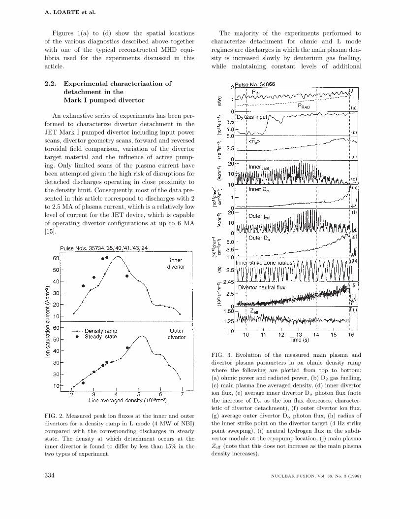
FIG. 2. Measured peak ion fluxes at the inner and outer
divertors for a density ramp in L mode (4 MW of NBI)
compared with the corresponding discharges in steady
state. The density at which detachment occurs at the
inner divertor is found to differ by less than 15% in the
two types of experiment.
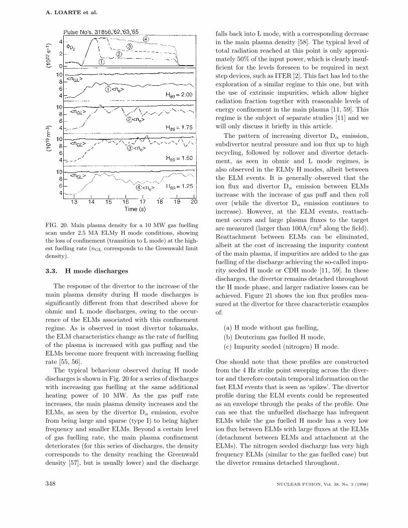
The majority of the experiments performed tocharacterize detachment for ohmic and L moderegimes are discharges in which the main plasma den-sity is increased slowly by deuterium gas fuelling,while maintaining constant levels of additional
FIG. 3. Evolution of the measured main plasma and
divertor plasma parameters in an ohmic density ramp
where the following are plotted from top to bottom:
(a) ohmic power and radiated power, (b) D2 gas fuelling,
(c) main plasma line averaged density, (d) inner divertor
ion flux, (e) average inner divertor Dα photon flux (note
the increase of Dα as the ion flux decreases, character-
istic of divertor detachment), (f) outer divertor ion flux,
(g) average outer divertor Dα photon flux, (h) radius of
the inner strike point on the divertor target (4 Hz strike
point sweeping), (i) neutral hydrogen flux in the subdi-
vertor module at the cryopump location, (j) main plasma
Zeff (note that this does not increase as the main plasma
density increases).
334 NUCLEAR FUSION, Vol. 38, No. 3 (1998)

ARTICLE PLASMA DETACHMENT IN JET
heating power (for L mode discharges). Theobvious advantage of this type of experiment is thatdifferent divertor regimes can be obtained under iden-tical machine conditions. This removes the uncer-tainty introduced by insufficient characterization ofthe machine conditions, which may vary within agiven series of discharges. The disadvantage of thisapproach is the lack of true steady state conditions forthese experiments and one may call into question therelevance of such results. However, it has been foundexperimentally that, provided the density ramps areperformed slowly enough (with respect to the typi-cal particle diffusion times), the density profiles havetime to adapt to the changing particle balance. Undersuch conditions, the results obtained from these den-sity ramps are similar to those obtained during steadystate density variation experiments in separate dis-charges, and hence the density ramps can be repre-sentative of a series of steady state density points.Typical density ramp speeds that guarantee quasi-steady-state particle balance in JET are (1.0–1.5)×1019 m−3 · s−1 for ohmic discharges and (1.5–2.0)×1019 m−3 ·s−1 for L mode discharges. A comparison ofthe measured maximum divertor ion fluxes versus lineaveraged density for a density ramp, together withthe corresponding steady state discharges in L modeis shown in Fig. 2, showing agreement to better than15%.
In the case of ELMy H mode discharges, densityramps are difficult to obtain experimentally since thedensity of the plasma appears to be more resilient togas fuelling than in ohmic and L mode discharges. Byusing the divertor cryopump it has been possible tovary the main plasma density by up to a factor of 2[16]. To study divertor detachment in this regime wehave performed gas fuelling scans on a shot by shotbasis, while the plasma density varies according tochanges in the ELM behaviour caused by the level ofgas fuelling.
3. BASIC OBSERVATIONS ONTHE APPROACH TO DETACHMENT
FOR DISCHARGESWITH FORWARD FIELD AND
VARIOUS CONFINEMENT REGIMES
3.1. Ohmic discharges
The typical evolution of the plasma parametersmeasured at the divertor and SOL during a quasi-steady-state density ramp is shown in Fig. 3. With
increasing main plasma density, the divertor evolvesthrough a series of well defined phases, which wedescribe in detail in the following sections.
3.1.1. Low recycling divertor
This phase is characteristic of low plasma den-sities during which the measured temperature gra-dients along the field line are small. The losses ofmomentum in the SOL are small in this regime and,hence, the static plasma pressure at the divertor tar-get is a factor of 2 smaller than that in the SOL, owingto the acceleration of ions to the velocity of sound atthe sheath — the Bohm criterion [17]. Numerical 2-Dsimulations of the SOL plasma for JET L mode dis-charges show that most of the pressure drop from theSOL to the divertor target occurs in the ion channel[18]. Owing to the different thermal conductivities ofions and electrons (parallel to B), the calculated iontemperature at the midplane is typically a factor of2 to 3 times larger than the electron temperature,while both temperatures are similar at the divertor.These modelling results are consistent with recentexperimental measurements in JT-60U [19] for simi-lar plasma conditions. As a consequence of this, theelectrons are in pressure balance over the whole of theSOL and divertor, within the experimental uncertain-ties of the position of the magnetic separatrix at thereciprocating Langmuir probe and divertor target.These features have been commonly observed in mostexperiments [20–22]. In fact, we use the assumptionof electron pressure balance during the low recyclingphase to accurately determine the distance betweenthe reciprocating probe and the magnetic separa-trix. Once the absolute offset of the magnetic cal-culations is determined in this way, the offset itselfis assumed to remain constant during the remainderof the density ramp. This experimentally determinedoffset is then used to correct the predicted (with MHDcodes) position of the separatrix for other phases ofthe discharge. Such a cross-calibration is needed toaccurately determine the change in parallel electronpressure for detached regimes where electron pressureconservation is no longer applicable.
One consequence of the small parallel temperaturegradient and pressure balance observed for low recy-cling divertors is that the divertor density is similarto that of the SOL, since there is little amplificationof the incident ion flux due to the re-ionization ofneutrals in the divertor. Under these conditions, itis found that the ratio of the total ion flux to thetotal Dα emission from the divertor is approximately
NUCLEAR FUSION, Vol. 38, No. 3 (1998) 335

A. LOARTE et al.
FIG. 4. Electron pressure, temperature and density in the SOL (triangles) and
the divertor (thick curves, inner divertor; thin curves, outer divertor) versus
distance to the separatrix mapped to the outer midplane at three different
times during an ohmic density ramp discharge: low recycling, high recycling
and detached divertor. The vertical dashed lines (in Fig. 3) indicate the times
at which the upstream SOL profile measurements are taken with the recipro-
cating probe.
20, which is in good agreement with the calculatedJohnson–Hinnov factor [23] (ionizations per Dα pho-ton emitted) for these measured plasma conditions.The profiles of electron pressure, density and tem-perature at both divertors and in the SOL are shownin Fig. 4. It is important to note that while the elec-tron pressure is similar at both divertors, the electrontemperature at the inner divertor is much lower thanthat at the outer divertor and, hence, the electrondensity is much higher at the inner divertor. This fea-ture is typical of discharges with forward toroidal field[24, 25] and is the cause of the inner divertor accessingthe high recycling and detached divertor regimes atlower main plasma densities. Hence, in Fig. 4 only theouter divertor is in the low recycling regime, while theinner divertor has already accessed the high recyclingregime, which is described below.
3.1.2. High recycling divertor
As the main plasma density increases, the diver-tor enters the high recycling regime in which largeelectron temperature gradients along the field line aremeasured and large amplification of the plasma flux isobserved at the divertor target. However, the electronpressure remains approximately conserved along thefield through the whole SOL and divertor and, con-sequently, the divertor density is considerably higherthan the SOL density. For the discharge shown inFigs 3 and 4 the peak outer divertor density increasesapproximately with 〈ne〉4 during this phase, while thetemperature decreases as 〈ne〉−2. This results in anapproximate increase of the measured peak ion fluxwith 〈ne〉3. These trends hold with increasing den-sity until the separatrix divertor temperature reaches
336 NUCLEAR FUSION, Vol. 38, No. 3 (1998)

ARTICLE PLASMA DETACHMENT IN JET
a value of 3 to 5 eV, at which point the peak ionflux density ceases to increase with main plasma den-sity (more quantitative comparisons for various dis-charges and conditions will be described in Section 6).During the high recycling phase, the appearance ofvery peaked ion flux profiles is frequently observed,and these will be described at the end of this section.Associated with this observation is the existence ofa region close to the separatrix in which the elec-tron pressure at the target exceeds the electron pres-sure at the SOL, as shown in Fig. 4 for the outerdivertor. While the detailed mechanism that leads tothis over-pressure remains unclear, this phenomenonis commonly observed in other divertor experiments,such as in high recycling discharges in Alcator C-Mod[26], where it is known as ‘death rays’. It should, how-ever, be noted that this over-pressure relies upon thecorrect determination of the electron temperature bydivertor Langmuir probes and this may be overesti-mated under these high recycling conditions, as dis-cussed further in Section 3.1.3.
The achievement of low temperatures at the diver-tor is observed to be fundamental in triggering theso-called ‘rollover’ and divertor detachment phase inall divertor experiments [8, 22, 27–29]. As the ionflux increases with the main plasma density, the neu-tral hydrogen pressure under the divertor and the Dα
emission from the outer divertor also increase (Fig. 3).The ratio of the integrated ion flux to the integratedDα emission from the outer divertor falls from a valueof 20, typical of low recycling conditions, to a value of5, which is consistent with the change in the Johnson–Hinnov factor expected for the decrease in tempera-ture and increase in density observed at the outerdivertor.
During the high recycling phase, the upstreamSOL density profiles are observed to broaden consid-erably (Fig. 4). This is expected from the enhancedionization in the divertor and the smaller neutralhydrogenic leakage to the main plasma, which leadsin turn to a reduced density gradient across theSOL. However, the divertor density profiles show aclear steepening in the region near the separatrix,which reflects the fact that local ionization, radiationand transport processes are dominating the diver-tor plasma during this phase [30]. The inner diver-tor undergoes the same transitions seen at the outerdivertor but at lower main plasma densities and,hence, while the outer divertor is in the high recyclingregime, the inner divertor has started to detach.
It is important to note that the main SOL sepa-ratrix electron pressure increases from the low recy-
cling to the high recycling phase, which is consis-tent with the increase in the main plasma densityand the fact that the power that crosses the sepa-ratrix, as estimated from the input power and thebolometers, remains approximately constant duringthis evolution. During the high recycling phase, theradiation emission peaks near the divertor targetand is very localized within the divertor legs, asdeduced from tomographic reconstructions of mea-surements by bolometer cameras in the divertor. InSection 3.1.3, we present detailed measurements ofthe divertor radiation profiles and the way in whichthey evolve as detachment progresses.
3.1.3. Rollover and divertor detachment phase
The beginning of the rollover phase is marked bythe start of a plateau in the time evolution of thepeak ion flux to the divertor target as the densityincreases. This is the primary experimental indica-tion that detachment processes are occurring in thedivertor. The typical level of radiated power at the so-called ‘rollover’ phase is around 55 to 70% of the totalinput power depending somewhat on the machineconditions and magnetic configuration. The rolloverphase starts first at the inner divertor and the sub-sequent time evolution is similar for both divertors,although the level of detachment reached at the innerdivertor is larger than that at the outer divertor whenthe density limit is attained. Initially, only the ionflux near the separatrix ceases to increase with den-sity, while it still rises in the outer regions of the SOL.As the density increases further, the ion flux near theseparatrix starts to fall, while the flux to the outerregions in the SOL may still be increasing. This fallof the ion flux marks the beginning of the detachmentphase. The region over which the ion flux falls widenswith increasing density (detachment region) until thelocation of maximum radiation moves away from thedivertor region and a MARFE (multifaceted asym-metric radiation from the edge) [31] is formed in themain plasma, and the discharge eventually disrupts.Before the main plasma MARFE is formed in JET,the ion flux has dropped everywhere across the innerdivertor while it has only decreased near the separa-trix in the outer divertor. The state of the divertorwhere the ion flux has decreased across the wholeSOL is known as total detachment (only seen in JETat the inner divertor), while the state in which onlythe ion flux close to the separatrix has decreased sig-nificantly is known as partial detachment [6].
NUCLEAR FUSION, Vol. 38, No. 3 (1998) 337

A. LOARTE et al.
FIG. 5. Evolution of the ion flux at the inner and outer
horizontal divertors and the inner and outer vertical
plates for an ohmic density ramp in JET. The modula-
tion of the ion flux measurements is due to strike point
sweeping during the discharge. There is no indication of
a strong increase of the ion flux on the vertical plates
beyond the rollover phase, as the ion flux to the horizon-
tal plate decreases.
The detailed divertor ion flux measurementsobtained in the JET Mark I divertor have eliminatedthe hypothesis that enhanced anomalous perpendicu-lar transport in the divertor explains plasma detach-ment, as observed in linear devices [32]. Accord-ing to this mechanism, the low electron temperatureand high neutral densities, characteristic of detacheddivertors, produce an enhanced perpendicular trans-port that increases radial particle losses to the sidewalls, thereby reducing the parallel ion flux incidenton the horizontal divertor target. This process is notobserved experimentally, as shown in Fig. 5, wherethe time evolutions of the ion fluxes to probes inthe horizontal inner and outer divertor targets andembedded in the side walls (which can be used asthe vertical divertor target) of the JET Mark I diver-
FIG. 6. Evolution of the separatrix electron density, tem-
perature and pressure measured with Langmuir probes
at the inner and outer divertors for an ohmic density
ramp in JET. Measurements of the electron temperature
deduced from C II VUV line ratios (904 and 1335 A) for
the inner divertor at several densities during the discharge
are shown for comparison.
tor are shown. These observations demonstrate thatthe fall in the ion flux to the horizontal divertor doesnot lead to any significant increase of the ion flux tothe side walls, in addition to that associated with theincrease of the main SOL plasma density in the outerregions of the SOL, which follows the increase in themain plasma density (note that the measured valuesof the ion flux to the side walls are 1 to 2 orders ofmagnitude lower than those measured at the horizon-tal target).
The beginning of the rollover and divertor detach-ment phase is correlated with the electron temper-ature in the divertor achieving values around 5 eV,as expected from simple models of plasma detach-ment [33, 34]. Figure 6 shows the evolution of theseparatrix electron pressure, density and tempera-ture (measured with Langmuir probes and C II VUVline ratio techniques) for the inner and outer diver-tors during such a density ramp. As the main plasmadensity increases the divertor temperature decreases
338 NUCLEAR FUSION, Vol. 38, No. 3 (1998)

ARTICLE PLASMA DETACHMENT IN JET
and, correspondingly, the divertor density increases,maintaining a constant or increasing divertor pres-sure. When the electron temperature reaches valuesclose to 5 eV, the electron pressure starts to decrease(as does the peak ion flux to the divertor), indicatingthe onset of detachment.
It is important to remark that during the highrecycling and rollover phase, the Langmuir I–V char-acteristics measured by the divertor probes deviatefrom the idealized exponential form, which is usuallyutilized for the interpretation of these measurements.In particular, low ratios of electron to ion saturationcurrents are usually measured and typical resistivebehaviour of the electron current is seen at the innerdivertor [35]. To correct for the low electron satu-ration currents, we analyse the measurements follow-ing the ‘virtual’ double probe approach of Gunther etal. [36]. However, while the resistive effects are qual-itatively described by the resistive probe model ofGunther [37], this model is, in its present formula-tion (slab geometry among other assumptions), toosimple and its application to the experiment doesnot produce satisfactory results. Hence, we have notapplied any correction for the resistive effects seenat the inner divertor, which may lead to an over-estimate of the real electron temperature. This factis routinely confirmed by measurements of the innerdivertor electron temperature with line ratios of C II(904 and 1335 A) for the same discharge, which arealso shown in Fig. 6. It is important to note that thesespectroscopic measurements are not localized at thedivertor plate but are intrinsically linked to the ionemitting the line (C+) and, hence, are affected by thechange in the ionization mean free path of neutral car-bon. This is particularly important for the detachedphase, during which the temperature determined bythis method is likely to reflect the electron temper-ature near the X point, where most of the radiationis emitted, as will be described later. Hence, underthese conditions, the actual electron temperature atthe plate is likely to be lower than that determinedusing line ratio methods.
During the final stages of detachment, the sep-aratrix electron temperature at the outer divertor(determined from Langmuir probes) drops to valuesin the region of 2 to 3 eV. This drop of electrontemperature has also been confirmed by measure-ments from a thermal helium beam diagnostic [38],which views across the outer divertor leg at variousheights from the target up to the X point region. Fig-ure 7 shows such observations for an ohmic densityramp: with increasing density the electron tempera-
ture in the whole divertor leg decreases. Finally, whendetachment is achieved, the region of low tempera-ture (Te ≤ 10 eV) expands along the field lines fromthe divertor target up to the X point. However, oneshould note that the approximations associated withthe atomic physics model [39] used for the interpreta-tion of the helium beam diagnostic become question-able for Te < 5 eV. The final stage of the detachmentprocess is achieved when total detachment is reachedat the inner divertor and, subsequently, the region ofhigh radiation moves away from the divertor and aMARFE develops in the main chamber.
We will now consider in more detail the experimen-tal observations that characterize divertor detach-ment, specifically, the increase of the divertor Dα
and neutral pressure in the subdivertor volume asthe main plasma density increases, despite the dropin the ion flux to the divertor plates. In princi-ple, this seemingly contradictory observation can bequalitatively reconciled with the model for diver-tor detachment proposed by Stangeby [33], in whichthe plasma momentum flux is reduced by chargeexchange collisions with recycling neutrals in thedivertor. Charge exchange on its own can explainthe transition from high recycling to detachment [40],although the bifurcative nature of such a transitionis rarely seen in any experiment. As the divertorelectron temperature decreases to values approach-ing 5 eV, the charge exchange processes in the diver-tor begin to dominate over ionization processes, andneutrals produced at the divertor plate have a verylarge probability of being scattered back to the diver-tor before they are ionized. In this process, the neu-trals can carry to the target a significant fraction ofthe momentum of the incoming ions and, therefore,prevent the ion flux from increasing at the divertor.This mechanism removes the apparent incompatibil-ity of a low ion flux and a high neutral pressure in thedivertor region. The decrease of the Johnson–Hinnovfactor with decreasing temperatures also removes, inprinciple, the apparent incompatibility of a decreasein the divertor ionization source (decrease in the ionflux to the divertor) and the large Dα emission. Asthe temperature decreases, the number of ionizationsper Dα photon decreases and, correspondingly, theDα emission increases for a given ionization source.
However, when a detailed quantitative analysis ofthe measurements is performed, some difficulties forthis relatively simple picture arise with respect to thebehaviour of the ion flux and Dα emission. Firstly,the behaviour of the peak ion flux and its integral issubstantially different for the two divertor targets.
NUCLEAR FUSION, Vol. 38, No. 3 (1998) 339

A. LOARTE et al.
FIG. 7. Profiles of electron temperature at the outer diver-
tor leg from thermal helium beam measurements for an
ohmic density ramp, as a function of the height above the
divertor target and the main plasma line averaged den-
sity. At the highest densities, the outer divertor is par-
tially detached and a region of low electron temperature
extends between the divertor target and the X point.
This is illustrated in Fig. 8 for an ohmic densityramp: the peak ion flux decreases by a factor of 5for the outer divertor during the detachment pro-cess, while its integral barely decreases from its high-est value (high recycling point) during the rolloverand divertor detachment phase (characteristic of par-tial detachment). In the case of the inner divertorthe picture is completely different, as both the peakion flux and the integral decrease by more than anorder of magnitude during the rollover and diver-tor detachment phase (characteristic of total detach-ment). Using the measured total ion flux to bothdivertors, we have derived an empirical Johnson–Hinnov factor and compared it with that derived fromthe measured divertor parameters and the atomicdata from the ADAS [41] database (Fig. 8). While itis clear that the change in the Johnson–Hinnov factoris similar to that expected for the variation of plasmaparameters (and the small total ion flux drop) at theouter divertor during detachment, there is a large dis-crepancy between the calculated and measured fac-tors for the inner divertor. Experimental uncertain-ties in the exact value of the electron temperatureat the inner divertor do not allow a more precisedetermination of this discrepancy but are not enough,on their own, to explain it. For example, assumingTe = 2 eV and ne = 1018 m−3 for detached divertor
FIG. 8. Inner and outer divertor peak and integrated ion
fluxes along with experimentally determined and calcu-
lated (S/XB) Johnson–Hinnov factors for an ohmic den-
sity ramp. The outer divertor shows a decrease of the
peak ion flux with density, while the integrated ion flux
remains approximately constant, which characterizes par-
tial divertor detachment. The inner divertor shows a large
decrease of the peak ion flux and its integral, which is
characteristic of total divertor detachment. The experi-
mentally determined Johnson–Hinnov factor for the inner
divertor changes by approximately 2 orders of magnitude
from the low recycling to the detached phase.
conditions results in ∼1 photon per ionization com-pared with <0.1 for the directly measured value atthe inner divertor.
This discrepancy for the inner divertor is typi-cal of totally detached divertors (only seen at theinner divertor in JET). It provides an indication thatadditional processes that modify the ionization bal-ance, such as recombination, and the distribution ofthe deuterium atoms in the different excited states(such as Lα re-absorption [42]) are taking place inthe experiment, during total divertor detachment.There is indeed experimental evidence of these phe-nomena, for instance, in the increase of the measuredratio Dγ/Dα from the divertor as detachment pro-ceeds. This observation indicates that the excitedlevels of the deuterium atoms are more populatedthan the normal distribution governed by electronicexcitation/de-excitation, consistent with deuteriumrecombination taking place. New complete measure-ments of the hydrogen line and continuum emission
340 NUCLEAR FUSION, Vol. 38, No. 3 (1998)

ARTICLE PLASMA DETACHMENT IN JET
from Alcator C-Mod [43, 44] and ASDEX Upgrade[45] have shown this to be the case in these experi-ments. For some detached divertor discharges in JET,it is also observed that there is a decrease of theratio Lβ/Dα [46], which indicates that radiation re-absorption is also taking place at the inner divertor(Lα would be strongly re-absorbed for such condi-tions). The detailed interpretation of these measure-ments needs highly sophisticated atomic populationcalculations [47], in conjunction with realistic plasmamodelling [48] for these conditions. It is important toassess with these models the role and mechanisms ofthe plasma recombination processes that occur dur-ing total divertor detachment [18], as proposed inRef. [49] on the basis of simulation studies of the max-imum drop of the ion flux associated with momentumremoval by neutral particle interaction in the diver-tor.
At the final stages of divertor detachment, theDα emission and the radiation migrate towards theX point, where a very dense radiating region isformed (with MARFE-like structure). An exampleof such divertor Dα emission behaviour is shownin Fig. 9, together with the visible bremsstrahlungemission measured at the same position. From thebremsstrahlung emission, it is clear that a very denseplasma region is formed in the vicinity of the X point,with densities of the order of 1020 m−3 [10]. Theseare indeed the densities that are measured at thedivertor leg and the X point with the microwaveand interferometer diagnostics for these discharges, asshown in Fig. 10. The region of highest density movesaway from the divertor (outer target), up the diver-tor leg (outer leg), towards the X point, where thebremsstrahlung emission increases considerably, untilthe position of the peak radiation moves away fromthe divertor and a main plasma MARFE is formed.The same picture of migration away from the tar-get towards the X point can be inferred from theline integrals of the measured radiation emissivity inthe divertor, which is shown in Fig. 11. It is impor-tant to note that at the very late stages of detach-ment, the peak of the radiation emission is locatedwell above the X point in the main plasma. This isin agreement with the measurements of the recipro-cating probe shown in Fig. 4, which display a sub-stantial pressure drop at the main SOL separatrix,consistent with the decreased power flux across theseparatrix. Despite the migration of radiation abovethe X point region, the impurity concentration in themain plasma, as measured by Zeff derived from visi-ble bremsstrahlung, does not change significantly (as
shown in Fig. 3). This indicates either that the impu-rity concentration in the main plasma is not domi-nated by the divertor or that the impurities are wellconfined in this MARFE-like structure and do notdiffuse into the main plasma, despite their proximityto it during the detached divertor phase.
The use of strike point sweeping during these den-sity ramp experiments has allowed the detailed char-acterization of the shape of the ion flux profiles fromthe low recycling to the detached regime. It is rou-tinely observed that during the transition from thelow recycling to the high recycling regime, the ionflux profiles at the divertor develop a doubly peakedstructure with the dominant peak growing from theprivate flux region side of the separatrix [30]. Thispeak finally dominates the ion flux profiles during thehigh recycling phase and disappears as detachmentproceeds. The double peaks cannot be attributed tofield errors, since they are observed to be toroidallysymmetric and there are no locked modes associ-ated with these discharges. There are indications thatthe formation of these peaks is related to anoma-lous transport in the SOL and divertor region [50],but the detailed structure of these high recyclingpeaks has not yet been successfully reproduced [18].Figure 12 shows the measured ion flux profiles atthe outer divertor target during an ohmic densityramp to detachment, where the evolution of the highrecycling peaks is clearly displayed. Similar obser-vations of peaked ion profiles during high recyclingconditions have been made in Alcator C-Mod [26],where they are known as ‘death rays’. In this experi-ment, the appearance of these peaks has been linkedto anomalous transport of perpendicular momentum[18] in vertical plate divertors. Although this mecha-nism describes satisfactorily the observations of ver-tical plate discharges in Alcator C-Mod, it cannotexplain the observations from JET Mark I and Alca-tor C-Mod horizontal plate discharges.
3.2. L mode discharges
Similar general trends to those described above forohmic discharges are also observed in L mode neu-tral beam heated discharges. Hence, our descriptionof the processes taking place in L mode dischargeswill be less detailed than that for the ohmic dis-charges. L mode discharges exhibit the characteristicsof detachment at a higher density than the ohmic onesand also reach higher densities before the MARFE isformed in the main plasma, as expected from simplearguments based on the temperature of the
NUCLEAR FUSION, Vol. 38, No. 3 (1998) 341

A. LOARTE et al.
FIG. 9. Profiles of ion flux and electron temperature,
and of Dα, Be II and visible bremsstrahlung emission
from the divertor during low recycling, high recycling and
divertor detachment, for an ohmic density ramp in JET.
FIG. 10. Evolution of the plasma density for an ohmic
density ramp in JET at various locations within the
divertor: target, divertor leg and X point. These are mea-
sured respectively by the Langmuir probes embedded in
the target, a microwave diagnostic that views across the
divertor leg between the target and the X point and an
interferometer channel that passes through the X point.
The visible bremsstrahlung emission at the X point is
also shown for comparison.
FIG. 11. Evolution of the measured radiation along various chords within the divertor,
showing the radiation migration towards the X point during the detachment process.
342 NUCLEAR FUSION, Vol. 38, No. 3 (1998)

ARTICLE PLASMA DETACHMENT IN JET
FIG. 12. Measured ion flux profiles at the outer divertor
during an ohmic density ramp discharge. With increas-
ing density the profiles develop a second peak that grows
from the private flux region side of the separatrix and
dominates the ion flux profiles during the high recycling
phase (13.56 s). This peak disappears during the partially
detached phase (15.23 s).
divertor reaching a given low value (Te ≤ 5 eV) whendetachment sets in. This trend of increasing densitywith increasing power weakens at higher additionalheating power as the divertor radiative losses increasewith it.
As a consequence of the increase in divertor radia-tive losses, the overall increase in density range forL mode discharges obtained by using additional heat-ing is much smaller than that deduced from simplescalings based on power balance arguments such asns ∝ P
5/8input [51], where ns is the separatrix density
(which is assumed to be proportional to the aver-age density) and Pinput is the total input power. Thissubject will be discussed in more detail in Section 6,where the concept of the detachment window is intro-duced. The total radiation level at which detachmentstarts for L mode discharges is typically around 50to 60% (composed of 30 to 40% divertor and X pointradiation and 10 to 20% bulk radiation), for whicharound 50% of the power that enters the SOL is radi-ated in the divertor.
Measurements taken during an L mode densityramp to detachment (Fig. 13) confirm the experi-mental observations in ohmic discharges, with theappearance of a pressure drop along the field line,
FIG. 13. Evolution of main plasma and divertor param-
eters for an L mode density ramp in JET (4.6 MW of
additional heating). The vertical dashed lines indicate the
times at which the upstream SOL profile measurements
are taken with the reciprocating probe.
when the divertor electron temperature reaches val-ues close to 5 eV, as measured by Langmuir probes.The main SOL profiles (Fig. 14) broaden as the mainplasma density increases and, for instance, the pres-sure profile e-folding length mapped to the outer mid-plane increases from 1.3 to 1.6 cm at the beginningof detachment and finally to 2.1 cm just before theMARFE escapes from the divertor. The broaden-ing of the density profile is the dominant term inthis pressure profile broadening (2.2 cm (low recy-cling), 3.3 cm (high recycling), 4.0 cm (detached)),which raises questions about the possibility of hav-ing low interaction with the walls (high wall clear-ance) under high recycling and detached divertor
NUCLEAR FUSION, Vol. 38, No. 3 (1998) 343

A. LOARTE et al.
FIG. 14. Main SOL and outer divertor profiles of electron pressure, tempera-
ture and density versus distance from the separatrix at the outer midplane, at
three stages for the L mode density ramp shown in Fig. 13. Note the pressure
drop of more than an order of magnitude during the detached phase of the
discharge. During this phase, the electron temperature is 2 to 3 eV at the outer
divertor target, as measured with Langmuir probes. In order to extrapolate
the main SOL separatrix parameters, exponential fits have been applied and
are shown as the solid lines.
conditions. This observation also calls into questionthe influence of the detailed design of the divertorunder such detached conditions. In contrast to theohmic discharge shown above (Fig. 4), for L modedischarges the pressure in the main SOL, measuredby the reciprocating probe, does not decrease even atthe very late stages of detachment. This is consistentwith a significant proportion of the input power stillcrossing the separatrix during this phase.
Using the measured Dα emission from the diver-tor and the integrated divertor ion flux we have cal-culated the empirical Johnson–Hinnov factor for theL mode density ramp shown in Fig. 13. It exhibitsthe same trend observed for ohmic discharges, whichindicates that recombination is taking place, whentotal detachment is obtained in the inner divertor(Fig. 15). As seen in ohmic discharges, the para-
meter that controls the onset of plasma detachmentis also the electron temperature which reaches lowvalues (below 5 eV) when detachment sets in. Theselow values are also confirmed by spectroscopic obser-vations of C II VUV line ratios for the inner diver-tor and of the thermal helium beam for the outerdivertor.
One of the main characteristics that makesdetached divertor regimes attractive for next stepdevices is related to the increase of the radiated powerand plasma density in the divertor region, since notonly is the erosion of the components reduced by thereduction of the ion flux, but also volumetric losses(including ion–neutral interactions) in the divertordominate and the power deposited at the divertor tar-get decreases. This is indeed observed in the exper-iment, as shown in Fig. 16 for an L mode density
344 NUCLEAR FUSION, Vol. 38, No. 3 (1998)

ARTICLE PLASMA DETACHMENT IN JET
FIG. 15. Peak and integrated ion fluxes to the inner and
outer divertors for the L mode density ramp shown in
Fig. 13. The inner divertor shows the typical drop of
the peak and integrated ion fluxes, characteristic of total
divertor detachment, while the outer divertor shows the
drop of the peak value but not of the integrated value,
characteristic of partial divertor detachment. The empir-
ical Johnson–Hinnov factors derived from the integrated
ion flux and the measured divertor Dα emission are also
shown for comparison.
scan. In this figure, we compare the power depositedonto the inner and outer divertor plates as measuredby the Langmuir probes (PLP) and IR thermography(PIR). As the plasma accesses the high recycling and,subsequently, detached divertor regimes, the powerdeposited on the divertor plate decreases (in the caseof the IR thermography to below the detection limitof the JET diagnostic). It is also important to notethat the power associated with the potential energyof the electron–ion pairs that recombine at the plate(in this case less than 0.5 MW at each divertor) alsodecreases as detachment proceeds and the ion fluxdecreases, particularly at the inner divertor. Therewill be an additional, albeit smaller, contribution tothe power deposited at the plate from the poten-tial energy of molecular formation on the surface of∼4.4 eV per molecule that has not been included inthis analysis.
The detachment process in L mode is also simul-taneous with a movement of the radiation away fromthe divertor and, at the latter stages of plasma
FIG. 16. Power deposited onto the divertor from the
main plasma (radiation and input power), from IR ther-
mography (PIR) and that derived from Langmuir probes
(PLP = PION + PREC) for a series of L mode discharges
with increasing densities to divertor detachment. (a) Total
power balance, (b) power balance for the inner diver-
tor (PION is the sheath power measured with Langmuir
probes and PREC is the recombination power), (c) power
balance for the outer divertor. The power that is deposited
onto the divertor target as the plasma flux recombines
(PREC) is shown for comparison and is observed to
decrease during plasma detachment.
detachment, the radiation is concentrated in thevicinity of the X point. This is clearly seen in thetomographic reconstructions for the same L modedensity ramp (Fig. 17). However, as indicated alsoin this figure, the concentration of impurities (asgiven by Zeff) does not increase dramatically whendetachment sets in. This observation is consistentwith recent results from a multimachine radiationdatabase scaling [52], which show that the level of Zeff
in the main plasma is correlated to the level of radia-tion and the plasma density with very little influenceof the regime of the divertor (i.e. high recycling ordetached regime) during the experiment.
A distinctive feature of L mode detached plasmasis the occurrence of the so-called divertor oscillations[29]. These oscillations appear when the main plasmadensity is in the region of (4.0–6.0)×1019 m−3 and theadditional heating power exceeds 3.5 MW. At higherinput powers, the discharges undergo a transition tothe H mode regime and the situation becomes morecomplicated by the presence of edge localized modes
NUCLEAR FUSION, Vol. 38, No. 3 (1998) 345

A. LOARTE et al.
FIG. 17. Bolometer reconstruction profiles for the three
stages of the L mode density ramp in Figs 13 and 14. At
the onset of detachment the radiation peak moves away
from the divertor towards the X point. In spite of this, the
Zeff values do not increase significantly during this phase.
The box shown in the bottom left hand corner indicates
the mesh size used for the reconstruction.
(ELMs). Once the density goes through these values,the oscillations disappear and the evolution towardsdetachment follows in a similar way to that in ohmicdischarges.
Figure 18 shows the characteristic observationsduring divertor oscillations: periods of very low ionfluxes simultaneously at both the inner and the outerdivertor strike zones followed by large peaks in the ionfluxes with a repetition rate of approximately 10 Hz.During the low ion flux phase, the inner divertor Dα
decreases while the outer divertor Dα increases tomake the distribution more symmetric between thestrike zones. At the same time, the C II emissionfrom the divertor target plate is strongly reduced (asshown in the contour plot in Fig. 18) and the radi-ated power in the vicinity of the strike zones decreasesand that near the X point increases. As the ion fluxdecreases, the neutral flux under the inner strike zone(gauge No. 41) also shows a large drop, while at the
FIG. 18. Behaviour of divertor and core plasma parame-
ters during bistable divertor behaviour. Shown from top
to bottom are the ion flux to the divertor, divertor Dα
emission, neutral fluxes under the divertor, line integrated
density in the main plasma and at the edge, C II emission
from the divertor and radiated power from three bolome-
ter channels (SZ observes near the divertor inner and
outer strike points and XPT observes near the X point).
private flux region (gauge No. 23) the neutral fluxincreases.
These oscillations are not only seen at the diver-tor but also affect the plasma parameters in theouter regions of the core plasma. During the lowion flux phase, there is a significant increase in thecore plasma density and a decrease in the edgeplasma density, as deduced by using two interferom-eter chords viewing different regions of the plasma.The density increase during the low ion flux phaseis also measured by a light detection and ranging(LIDAR) Thompson scattering diagnostic andappears to be localized to the outer regions of the
346 NUCLEAR FUSION, Vol. 38, No. 3 (1998)

ARTICLE PLASMA DETACHMENT IN JET
FIG. 19. Measurements of the electron temperature pro-
file from ECE measurements at the edge of the main
plasma during the bistable behaviour of the divertor
plasma. At t = 0 ms the peak radiation is located at
the X point and at t = 15.99 ms the radiation peak has
moved back to the strike points.
main plasma, leading to the formation of a hollowdensity profile. Measurements of the electron tem-perature profile at the outer edge of the main plasmafrom an ECE heterodyne radiometer diagnostic areshown in Fig. 19. As the plasma density rises in theedge of the core plasma, the electron temperature fallssharply in the outermost 20 cm (r > 0.7a), this fallappearing to propagate from the plasma edge towardsthe centre. The electron temperature profile contractsduring the low ion flux phase (labelled as 0.00 ms) andrecovers over a period of 16 ms, after which the diver-tor is fully attached. By further increasing the mainplasma density via gas fuelling, the oscillation fre-quency decreases until the oscillations cease. Beyondthe density window over which the oscillations occur,the divertor plasma can be driven further into detach-ment to eventually reach the density limit. The oscil-lations are observed in the density rampup (stronggas puff) to detachment and rampdown (weak or nogas puff) and, hence, are not due to a fuelling effect.It is interesting to note that these oscillations havealso been induced during experiments in which neonis injected in short bursts into the divertor region, butthat they are not generally observed during verticalplate and reversed toroidal field discharges.
Given that the occurrence of the oscillatory diver-tor behaviour requires a minimum level of additionalheating power and main plasma density, we believethat the observed phenomena are caused by impurityproduction from the divertor target. A possible inter-pretation of the observation is as follows: during thehigh ion flux phase, carbon production reaches a max-imum; this leads to the radiation moving above theX point and, hence, to a sharp decrease of the powerthat crosses the separatrix. After this period, theplasma is effectively totally detached from all mate-rial surfaces and the impurity production decreases,leading to a decrease in the radiation and to the re-attachment. The exact reasons as to why the MARFEbecomes stabilized around the X point when the den-sity is increased further and the oscillations cease arenot understood.
Similar observations of oscillatory divertorbehaviour have also been reported in ASDEXUpgrade [53, 54]. In that case, the oscillatorybehaviour was attributed to the gas feedback sys-tem, which reacted to the increase in main plasmadensity as the MARFE moved up to the X pointregion. In JET, the gas fuelling feedback system hasan overall response time greater than 150 ms and,therefore, is too slow to react at oscillation frequen-cies that are typically observed. Transport phenom-ena in the SOL will occur on a time-scale of a fewmilliseconds, i.e. much more rapidly than the divertoroscillations. The time-scale of the oscillations is moreconsistent with diffusive processes at the edge of thecore plasma. While the mechanism proposed abovemay account for many of the experimental observa-tions, it is clear that the phenomena associated withthe self-sustained divertor oscillations are extremelycomplex and involve changes in plasma parameters inboth the divertor and the core plasma region.
Despite the occurrence of such oscillations, theregime of divertor detachment in L mode, in whichthe inner divertor is totally detached while the outerdivertor is partially detached, has proven to be afairly robust regime. It has been possible to keepthe divertor in this regime by means of feedbackcontrol of the gas puff on the level of the ion fluxto the inner divertor [13]. In this experiment, theplasma was driven to detachment by feedforward con-trol of the gas puff and subsequently maintainedin the detached state by controlling the gas puff(increasing or decreasing it) as the divertor fluxincreased (attachment) or decreased (too detached)with respect to a reference ion flux feedback requestwaveform.
NUCLEAR FUSION, Vol. 38, No. 3 (1998) 347
A. LOARTE et al.
FIG. 20. Main plasma density for a 10 MW gas fuelling
scan under 2.5 MA ELMy H mode conditions, showing
the loss of confinement (transition to L mode) at the high-
est fuelling rate (nGL corresponds to the Greenwald limit
density).
3.3. H mode discharges
The response of the divertor to the increase of themain plasma density during H mode discharges issignificantly different from that described above forohmic and L mode discharges, owing to the occur-rence of the ELMs associated with this confinementregime. As is observed in most divertor tokamaks,the ELM characteristics change as the rate of fuellingof the plasma is increased with gas puffing and theELMs become more frequent with increasing fuellingrate [55, 56].
The typical behaviour observed during H modedischarges is shown in Fig. 20 for a series of dischargeswith increasing gas fuelling at the same additionalheating power of 10 MW. As the gas puff rateincreases, the main plasma density increases and theELMs, as seen by the divertor Dα emission, evolvefrom being large and sparse (type I) to being higherfrequency and smaller ELMs. Beyond a certain levelof gas fuelling rate, the main plasma confinementdeteriorates (for this series of discharges, the densitycorresponds to the density reaching the Greenwalddensity [57], but is usually lower) and the discharge
falls back into L mode, with a corresponding decreasein the main plasma density [58]. The typical level oftotal radiation reached at this point is only approxi-mately 50% of the input power, which is clearly insuf-ficient for the levels foreseen to be required in nextstep devices, such as ITER [2]. This fact has led to theexploration of a similar regime to this one, but withthe use of extrinsic impurities, which allow higherradiation fraction together with reasonable levels ofenergy confinement in the main plasma [11, 59]. Thisregime is the subject of separate studies [11] and wewill only discuss it briefly in this article.
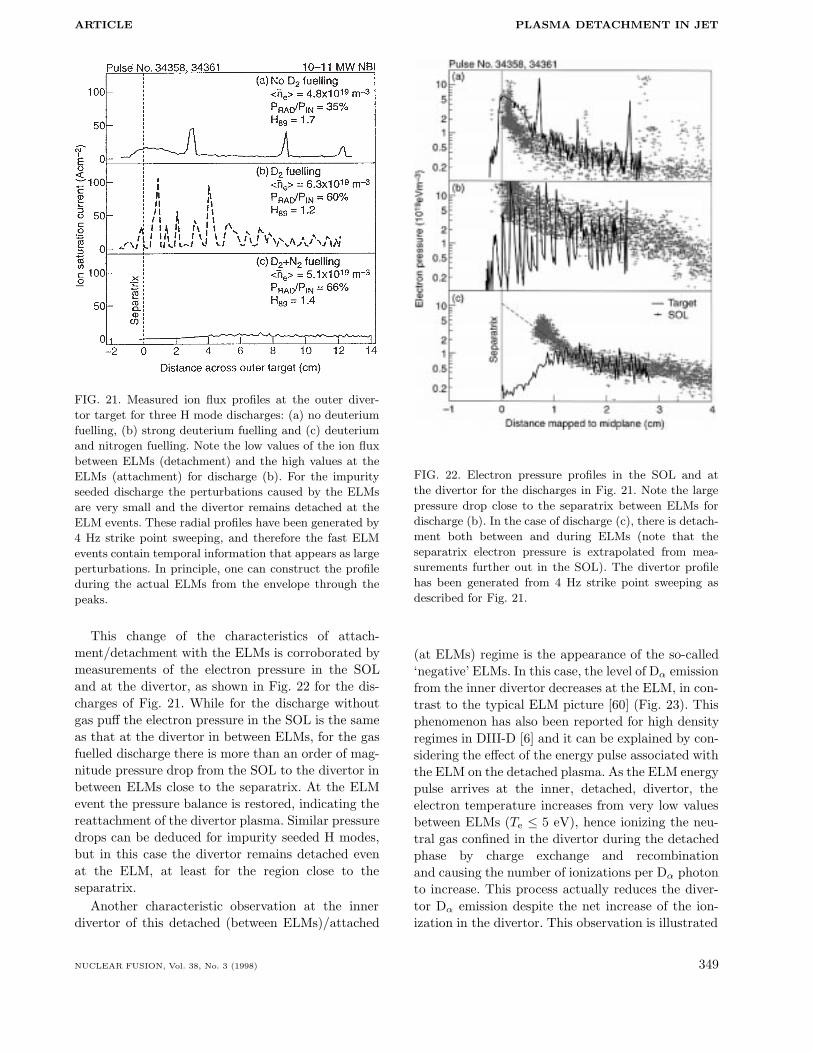
The pattern of increasing divertor Dα emission,subdivertor neutral pressure and ion flux up to highrecycling, followed by rollover and divertor detach-ment, as seen in ohmic and L mode regimes, isalso observed in the ELMy H modes, albeit betweenthe ELM events. It is generally observed that theion flux and divertor Dα emission between ELMsincrease with the increase of gas puff and then rollover (while the divertor Dα emission continues toincrease). However, at the ELM events, reattach-ment occurs and large plasma fluxes to the targetare measured (larger than 100A/cm2 along the field).Reattachment between ELMs can be eliminated,albeit at the cost of increasing the impurity contentof the main plasma, if impurities are added to the gasfuelling of the discharge achieving the so-called impu-rity seeded H mode or CDH mode [11, 59]. In thesedischarges, the divertor remains detached throughoutthe H mode phase, and larger radiative losses can beachieved. Figure 21 shows the ion flux profiles mea-sured at the divertor for three characteristic examplesof:
(a) H mode without gas fuelling,(b) Deuterium gas fuelled H mode,(c) Impurity seeded (nitrogen) H mode.
One should note that these profiles are constructedfrom the 4 Hz strike point sweeping across the diver-tor and therefore contain temporal information on thefast ELM events that is seen as ‘spikes’. The divertorprofile during the ELM events could be representedas an envelope through the peaks of the profile. Onecan see that the unfuelled discharge has infrequentELMs while the gas fuelled H mode has a very lowion flux between ELMs with large fluxes at the ELMs(detachment between ELMs and attachment at theELMs). The nitrogen seeded discharge has very highfrequency ELMs (similar to the gas fuelled case) butthe divertor remains detached throughout.
348 NUCLEAR FUSION, Vol. 38, No. 3 (1998)
ARTICLE PLASMA DETACHMENT IN JET
FIG. 21. Measured ion flux profiles at the outer diver-
tor target for three H mode discharges: (a) no deuterium
fuelling, (b) strong deuterium fuelling and (c) deuterium
and nitrogen fuelling. Note the low values of the ion flux
between ELMs (detachment) and the high values at the
ELMs (attachment) for discharge (b). For the impurity
seeded discharge the perturbations caused by the ELMs
are very small and the divertor remains detached at the
ELM events. These radial profiles have been generated by
4 Hz strike point sweeping, and therefore the fast ELM
events contain temporal information that appears as large
perturbations. In principle, one can construct the profile
during the actual ELMs from the envelope through the
peaks.
This change of the characteristics of attach-ment/detachment with the ELMs is corroborated bymeasurements of the electron pressure in the SOLand at the divertor, as shown in Fig. 22 for the dis-charges of Fig. 21. While for the discharge withoutgas puff the electron pressure in the SOL is the sameas that at the divertor in between ELMs, for the gasfuelled discharge there is more than an order of mag-nitude pressure drop from the SOL to the divertor inbetween ELMs close to the separatrix. At the ELMevent the pressure balance is restored, indicating thereattachment of the divertor plasma. Similar pressuredrops can be deduced for impurity seeded H modes,but in this case the divertor remains detached evenat the ELM, at least for the region close to theseparatrix.
Another characteristic observation at the innerdivertor of this detached (between ELMs)/attached
FIG. 22. Electron pressure profiles in the SOL and at
the divertor for the discharges in Fig. 21. Note the large
pressure drop close to the separatrix between ELMs for
discharge (b). In the case of discharge (c), there is detach-
ment both between and during ELMs (note that the
separatrix electron pressure is extrapolated from mea-
surements further out in the SOL). The divertor profile
has been generated from 4 Hz strike point sweeping as
described for Fig. 21.
(at ELMs) regime is the appearance of the so-called‘negative’ ELMs. In this case, the level of Dα emissionfrom the inner divertor decreases at the ELM, in con-trast to the typical ELM picture [60] (Fig. 23). Thisphenomenon has also been reported for high densityregimes in DIII-D [6] and it can be explained by con-sidering the effect of the energy pulse associated withthe ELM on the detached plasma. As the ELM energypulse arrives at the inner, detached, divertor, theelectron temperature increases from very low valuesbetween ELMs (Te ≤ 5 eV), hence ionizing the neu-tral gas confined in the divertor during the detachedphase by charge exchange and recombinationand causing the number of ionizations per Dα photonto increase. This process actually reduces the diver-tor Dα emission despite the net increase of the ion-ization in the divertor. This observation is illustrated
NUCLEAR FUSION, Vol. 38, No. 3 (1998) 349

A. LOARTE et al.
FIG. 23. Main plasma and inner divertor parameters for a
discharge in which a gas fuelling rate scan is performed in
ELMy H mode conditions. As the fuelling rate is increased
with time, the ELMs, as measured by the Dα emission
from the inner divertor, evolve into ‘negative’ ELMs, as
detachment between ELMs starts. Note that at the ELMs
the divertor reattaches again, as shown by the large mea-
sured values of the ion flux at the inner divertor.
in detail in Fig. 24 for a discharge with the Mark Iberyllium target, where the divertor Dα emission pro-file, Be II emission profile and ion flux to the diver-tor target are compared for a high density dischargewith 15 MW of neutral beam injection (NBI) (that ofFig. 23), where the inner divertor is detached whilethe outer divertor remains attached. Between ELMs,the inner divertor Dα emission signal is saturatedand decreases at the ELM (‘negative’ ELMs), while itincreases at the outer divertor in the normal fashion.However, for both divertors the ion flux increases atthe ELM event. This confirms that the inner divertoris detached between the ELMs and reattaches at theELM. It is important to remark that no significant
increase of the Be II emission is observed at eitherdivertor at the ELM, with the levels being negligiblefor the inner divertor. This lack of beryllium emissionfrom the inner divertor is consistent with a very lowdivertor temperature even at the ELM since, as hasbeen established experimentally in JET, beryllium isproduced by physical sputtering processes that havea very low energy threshold (10 to 20 eV incident ionenergy, depending on the degree of oxidation) [61].Consequently, as soon as the electron temperatureincreases beyond 5 eV, a significant Be II emissionwould be expected (see Section 5 for a more detaileddiscussion on this topic).
FIG. 24. Divertor Dα, Be II and ion flux to the divertor
between ELMs (full curves, note that the inner divertor
Dα signal is saturated) and at the ELMs (dashed curves),
showing the detachment between ELMs and reattachment
at the ELMs during the high density ELMy H mode dis-
charge of Fig. 23. Note that the divertor ion flux profile
has been generated from 4 Hz strike point sweeping as
described for Fig. 21, which artifically shows the ELM
events as spatially resolved perturbations to the profile
shape.
350 NUCLEAR FUSION, Vol. 38, No. 3 (1998)

ARTICLE PLASMA DETACHMENT IN JET
4. EFFECTS OF DIVERTOR GEOMETRY,WALL CLEARANCE
TOROIDAL FIELD DIRECTIONAND DIVERTOR PUMPING
ON DIVERTOR DETACHMENT
4.1. Effects of divertor geometry andwall clearance on plasma detachment
A systematic study has been performed at JETto understand the effect of divertor geometry on theonset and stability of plasma detachment. During thisstudy, it was found that there is an additional fac-tor that affects detachment at least as much as thedivertor geometry: the clearance between the sep-aratrix and the nearest material surface. This dis-covery somewhat complicates the study of divertorgeometry effects as, in changing the divertor geome-try, the clearance from the wall is also unavoidablyvaried. Hence, we will firstly discuss the observedeffect of a controlled change of the wall clearanceon plasma detachment with fixed divertor geometrybefore describing the effect of the divertor geometryon detachment.
In ohmic discharges, it has been found that dis-charges that are well separated from the walls (whereapproximately the 5 cm line in the SOL, mapped tothe outer midplane, intersects a material surface out-side the divertor) have a higher density threshold fordetachment and density limit by about 35% [29] thanthose that have less clearance from the walls (2.5 cmmapped to the outer midplane). The proximity of thewalls also affects the split between the bulk and thecombined divertor plus X point radiation, which isabout one third bulk and two thirds divertor plusX point for high clearance discharges, while it is onehalf bulk and one half divertor plus X point for lowclearance discharges. A comparison of two identicaldischarges, except for the clearance to the top of thetorus, is shown in Figs 25(a) and (b), exhibiting thetypical features illustrative of the influence of wallclearance on the main plasma parameters and diver-tor detachment.
The influence of wall clearance in L mode andH mode detachment is found to be much weaker (10to 15% difference in main plasma density to achievedetachment) [29]. A possible explanation of this effectis that the L mode profiles tend to broaden verystrongly at the beginning of detachment, as discussedin Section 3.2 and, hence, in all configurations thereis some degree of interaction with the walls for thesedischarges. In the case of H mode detachment, dur-
FIG. 25. (a) MHD equilibrium for two identical ohmic
discharges with different wall clearances to the top of
the machine. (b) Main discharge and divertor parameters
(full curves, low clearance; dashed curves, high clearance),
showing the lower detachment threshold and density limit
for the discharge that has the strongest interaction with
the walls. It is also evident that the proportion of bulk
plasma radiation is higher for the low clearance discharge.
ing ELM events the SOL is observed to broaden con-siderably and the same argument applies due to theinteraction of the ELMs with the main chamber walls[62].
Because of the unavoidable change of wall clear-ance with divertor geometry in the experiments, inparticular with the variation of the divertor flux
NUCLEAR FUSION, Vol. 38, No. 3 (1998) 351

A. LOARTE et al.
FIG. 26. MHD equilibrium reconstructions of typical con-
figurations used for studies of the influence of the mag-
netic geometry on plasma detachment. The flux surfaces
correspond to a spacing of 1 cm at the outer midplane.
expansion, we have divided the study of the influenceof divertor geometry on detachment into two sepa-rate sets of experiments. Figure 26 shows the MHDequilibria reconstructions for the four typical config-urations used in this study.
4.1.1. Divertor geometry variation with ‘fixed’magnetic configuration: vertical/horizontalcomparison at low perpendicular fluxexpansion
There are no substantial differences in the accessto detachment for similar discharges in horizontal andvertical divertor configurations. Detachment occursat similar plasma density, gas fuelling rate and radi-ation levels for both cases in ohmic, L mode andH mode regimes.
This observation is in contrast to expectationsfrom 2-D modelling calculations of the closure to neu-trals of both configurations [63, 64]. This discrep-ancy is believed to be due to the existence of bypassleaks for neutrals from the divertor to the main cham-ber (which are present in the experiment and not inthe original calculations) and the possible existenceof an inward particle pinch in the SOL [65]. Bothfactors, when taken into account, modify substan-tially the neutral re-ionization pattern and the calcu-lated divertor closure and therefore the dependence
of detachment on the divertor geometry. For verti-cal plate discharges with a forward field, detachmentseems to take place more symmetrically between theinner and the outer divertor, while in the horizontalplate the inner divertor tends to detach first, as thedensity is increased (further discussed in Section 6).
Detailed comparison of the ion flux profiles at thedivertor plate for ohmic and L mode discharges showsthat the profiles are somewhat steeper (in outer mid-plane co-ordinates) when the separatrix is located atthe lower part of the vertical plate than the profiles ofthe horizontal plate divertor. This trend is expectedfrom modelling calculations [64, 66] as a consequenceof the preferential ionization of neutrals at the sepa-ratrix in the case of vertical plate divertors, althoughthe size of the effect is much smaller in the experimentthan from the modelling calculations. The differencesin the temperature profiles between horizontal andvertical divertors are very small within the experi-mental errors.
A characteristic behaviour of vertical plate diver-tor discharges, not found for discharges on the hor-izontal plate, is the sensitivity of detachment to theexact position of the strike point on the vertical plate[64]. When the divertor strike points are swept acrossthe horizontal divertor plate, no noticeable differ-ence is seen in the ion flux profiles measured withprobes at different positions in the target. In this case,the profiles maintain the same shape and degree ofdetachment as the strike point moves across the diver-tor target. However, when the strike point is sweptacross the vertical plate, the profiles of ion flux andthe degree of detachment may change considerably,depending on the position of the strike point. Whilethe divertor is detached when the strike point is atthe lower part of the vertical plate (near the cornerbetween the vertical plate and the horizontal plate),the plasma re-attaches as the strike point moves tothe upper part of the vertical plate (Fig. 27 shows anL mode example). This strong dependence of detach-ment on the strike point position on the vertical plateis consistent with expectations of the estimated diver-tor closure for neutrals in both geometric configura-tions on the vertical plate [64]. Such an effect is dueto the increased probability of neutral ionization nearthe separatrix occurring in the vertical plate configu-ration, which promotes the achievement of low diver-tor electron temperatures and subsequently detach-ment. However, it is important to note that the degreeof detachment achieved on any zone of the verticalplate is never larger than that obtained on the hori-zontal plate, and this goes against our general expec-
352 NUCLEAR FUSION, Vol. 38, No. 3 (1998)

ARTICLE PLASMA DETACHMENT IN JET
FIG. 27. Ion flux profiles at the outer divertor, during an L mode density ramp
discharge in the high recycling and detached divertor phases. Profiles are shown
for two probes on the vertical plate (squares, upper part of the vertical plate;
triangles, lower part of the vertical plate). The degree of detachment differs
substantially at each probe position, being much larger when the separatrix is
located in the lower part of the vertical plate.
tations and is not yet fully understood.In summary, vertical and horizontal divertor dis-
charges display very similar characteristics in theapproach to detachment, and operation on the ver-tical plate does not lead to a larger operating rangefor detached plasmas, in contrast to original expec-tations from code calculations. While there is evi-dence that part of this behaviour can be attributedto the existence of bypasses for neutrals to escapefrom the divertor into the main chamber and SOLplasma perpendicular transport processes, the simi-larities between vertical and horizontal divertor arenot yet fully understood.
4.1.2. Divertor magnetic geometry variationon horizontal plates
The strongest effect of the divertor magnetic geom-etry on detachment seen in the experiment is asso-ciated with the increase of flux surface separation(flux expansion) at the divertor target. For ohmicdischarges, it has been found that discharges withlower flux expansion (inner divertor 4.9, outer diver-tor 2.1) have a threshold density for detachment anda density limit that is about 30 to 40% larger thanthat of a similar discharge with higher flux expan-sion (inner divertor 6.3, outer divertor 3.2) (Fig. 28).The open question regarding this comparison is thefact that the clearance from the walls (particularly
to the inner divertor wall and to the top of the ves-sel) is significantly decreased when the divertor fluxexpansion is increased (from 5 cm at the midplanefor low flux expansion to 2.5 cm for large flux expan-sion). This change in clearance may be the dominanteffect that accounts for the observations, rather thanthe flux expansion itself. The split between diver-tor radiation and main plasma radiation seems tobe consistent with the wall clearance being the dom-inant factor: for low flux expansion discharges theradiation split is approximately one third bulk radia-tion and two thirds divertor radiation, while for highflux expansion the split is one half bulk to one halfdivertor radiation. This observation is in agreementwith those from discharges in which just the wallclearance is changed without needing to include anyadditional effect of changing the divertor geometry.Measurements of the carbon radiation in the visibleand VUV wavelengths from the inner divertor indi-cate that the contribution of carbon to the measuredradiation dominates as the clearance to the innerdivertor wall is reduced (see Section 5 for a detaileddiscussion).
A similar behaviour is found in L mode andH mode discharges, although the differences betweenconfigurations are somewhat smaller (Fig. 29). Thereason is likely to be associated with a strongerinteraction with the walls for any configurationcaused by the ELMs or the flattening of the SOL
NUCLEAR FUSION, Vol. 38, No. 3 (1998) 353

A. LOARTE et al.
profiles in the approach to detachment for L modedensity ramps.
4.2. Effects of the toroidal field directionon divertor detachment
Dedicated experiments have been carried out inJET to compare the effect of the toroidal field direc-tion on detachment. Reversed toroidal field ohmicand L mode discharges tend to display more sym-metric divertor parameters between the inner andthe outer divertor [67] for, otherwise, identical coreplasma parameters. This leads, in horizontal diver-tor high clearance configurations, to detachment tak-ing place more symmetrically at the inner and theouter divertors for the reversed field discharges. How-ever, in contrast to forward field discharges which arefairly stable, reversed field discharges tend to forma MARFE in the main plasma as soon as detach-ment starts at the outer divertor. The trend of theradiation to escape from the divertor in reversedfield discharges had been observed previously in theJET 1991/92 experimental campaign [68], ASDEXUpgrade [54, 69] and JT-60U [12] and is not wellunderstood. A comparison of two ohmic discharges,identical but for the toroidal field direction, is shownin Fig. 30, with arrows indicating the onset of detach-ment. In general, it is observed that, for comparablemain plasma densities, the Zeff values measured inforward and reversed field discharges are similar and,hence, increased impurity levels in the main plasmafor reversed field discharges (as proposed in Ref. [69])can be ruled out as the explanation for this behaviourin the JET experiments.
The more symmetric approach to detachment inreversed field discharges is, however, not seen in allmagnetic configurations. In particular, vertical plateand corner configurations are more symmetric in theapproach to detachment with forward direction of thefield. Figure 31 shows two discharges in the cornerconfiguration with different directions of the toroidalfield. The unstable approach to detachment of thereversed field discharges is again clearly seen and,hence, does not depend on details of the magneticconfiguration but principally on the direction of thetoroidal field.
L mode discharges behave similarly to ohmic oneswith respect to the dependence of detachment on thetoroidal field direction. Therefore, it has not beenpossible to obtain steady state L mode detached dis-charges with reversed field. Although the instability
FIG. 28. Plasma density, total radiation and ion flux to
the inner and outer divertors for two ohmic horizontal
divertor discharges with low flux expansion (full curve)
and high flux expansion (dashed curve).
FIG. 29. Input power, total radiation, plasma density, ion
flux and Dα to the inner divertor for two L mode hor-
izontal divertor discharges with low flux expansion (full
curves) and high flux expansion (dashed curves).
of divertor detachment in the reversed field case isnot understood, it highlights one of the major disad-vantages of operating the JET device with this direc-tion of the toroidal field. Although the power loadmay be more symmetric for reversed field in some
354 NUCLEAR FUSION, Vol. 38, No. 3 (1998)
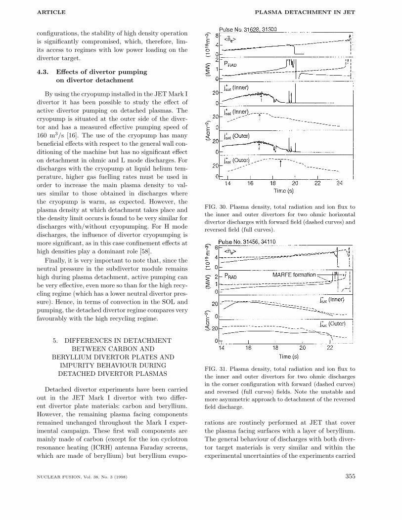
ARTICLE PLASMA DETACHMENT IN JET
configurations, the stability of high density operationis significantly compromised, which, therefore, lim-its access to regimes with low power loading on thedivertor target.
4.3. Effects of divertor pumpingon divertor detachment
By using the cryopump installed in the JET Mark Idivertor it has been possible to study the effect ofactive divertor pumping on detached plasmas. Thecryopump is situated at the outer side of the diver-tor and has a measured effective pumping speed of160 m3/s [16]. The use of the cryopump has manybeneficial effects with respect to the general wall con-ditioning of the machine but has no significant effecton detachment in ohmic and L mode discharges. Fordischarges with the cryopump at liquid helium tem-perature, higher gas fuelling rates must be used inorder to increase the main plasma density to val-ues similar to those obtained in discharges wherethe cryopump is warm, as expected. However, theplasma density at which detachment takes place andthe density limit occurs is found to be very similar fordischarges with/without cryopumping. For H modedischarges, the influence of divertor cryopumping ismore significant, as in this case confinement effects athigh densities play a dominant role [58].
Finally, it is very important to note that, since theneutral pressure in the subdivertor module remainshigh during plasma detachment, active pumping canbe very effective, even more so than for the high recy-cling regime (which has a lower neutral divertor pres-sure). Hence, in terms of convection in the SOL andpumping, the detached divertor regime compares veryfavourably with the high recycling regime.
5. DIFFERENCES IN DETACHMENTBETWEEN CARBON AND
BERYLLIUM DIVERTOR PLATES ANDIMPURITY BEHAVIOUR DURING
DETACHED DIVERTOR PLASMAS
Detached divertor experiments have been carriedout in the JET Mark I divertor with two differ-ent divertor plate materials: carbon and beryllium.However, the remaining plasma facing componentsremained unchanged throughout the Mark I exper-imental campaign. These first wall components aremainly made of carbon (except for the ion cyclotronresonance heating (ICRH) antenna Faraday screens,which are made of beryllium) but beryllium evapo-
FIG. 30. Plasma density, total radiation and ion flux to
the inner and outer divertors for two ohmic horizontal
divertor discharges with forward field (dashed curves) and
reversed field (full curves).
FIG. 31. Plasma density, total radiation and ion flux to
the inner and outer divertors for two ohmic discharges
in the corner configuration with forward (dashed curves)
and reversed (full curves) fields. Note the unstable and
more asymmetric approach to detachment of the reversed
field discharge.
rations are routinely performed at JET that coverthe plasma facing surfaces with a layer of beryllium.The general behaviour of discharges with both diver-tor target materials is very similar and within theexperimental uncertainties of the experiments carried
NUCLEAR FUSION, Vol. 38, No. 3 (1998) 355
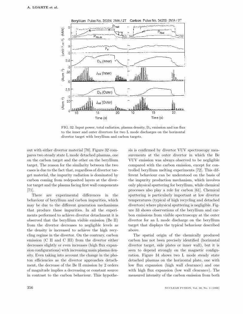
A. LOARTE et al.
FIG. 32. Input power, total radiation, plasma density, Dα emission and ion flux
to the inner and outer divertors for two L mode discharges on the horizontal
divertor target with beryllium and carbon targets.
out with either divertor material [70]. Figure 32 com-pares two steady state L mode detached plasmas, oneon the carbon target and the other on the berylliumtarget. The reason for the similarity between the twocases is due to the fact that, regardless of divertor tar-get material, the impurity radiation is dominated bycarbon coming from redeposited layers at the diver-tor target and the plasma facing first wall components[71].
There are experimental differences in thebehaviour of beryllium and carbon impurities, whichmay be due to the different generation mechanismsthat produce these impurities. In all the experi-ments performed to achieve divertor detachment it isobserved that the beryllium visible emission (Be II)from the divertor decreases to negligible levels asthe density is increased to achieve the high recy-cling regime in the divertor. On the contrary, carbonemission (C II and C III) from the divertor eitherdecreases slightly or even increases (high flux expan-sion configurations) with increasing main plasma den-sity. Even taking into account the change in the pho-ton efficiencies as the divertor approaches detach-ment, the decrease of the Be II emission by 2 ordersof magnitude implies a decreasing or constant sourcein contrast to the carbon behaviour. This hypothe-
sis is confirmed by divertor VUV spectroscopy mea-surements at the outer divertor in which the BeVUV emission was always observed to be negligiblecompared with the carbon emission, except for con-trolled beryllium melting experiments [72]. This dif-ferent behaviour can be understood on the basis ofthe impurity production mechanism, which involvesonly physical sputtering for beryllium, while chemicalprocesses also play a role for carbon [61]. Chemicalsputtering is particularly important at low divertortemperatures (typical of high recycling and detacheddivertors) where physical sputtering is negligible. Fig-ure 33 shows observations of the beryllium and car-bon emissions from visible spectroscopy at the outerdivertor for an L mode discharge on the berylliumtarget that displays the typical behaviour describedabove.
The spatial origin of the chemically producedcarbon has not been precisely identified (horizontaldivertor target, side plates or inner wall), but it isseen to depend strongly on the magnetic configu-ration. Figure 34 shows two L mode steady statedetached plasmas on the horizontal plate, one withlow flux expansion (high wall clearance) and onewith high flux expansion (low wall clearance). Themeasured intensity of the carbon emission from both
356 NUCLEAR FUSION, Vol. 38, No. 3 (1998)
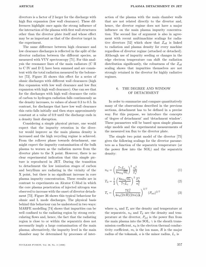
ARTICLE PLASMA DETACHMENT IN JET
divertors is a factor of 2 larger for the discharge withhigh flux expansion (low wall clearance). These dif-ferences highlight once again the strong influence ofthe interaction of the plasma with first wall structuresother than the divertor plate itself and whose effectmay be as important as that of the divertor target inthe experiment.
The same difference between high clearance andlow clearance discharges is reflected in the split of thedivertor radiation between the different species, asmeasured with VUV spectroscopy [71]. For this anal-ysis the resonance lines of the main radiators (C IIto C IV and D I) have been summed and are consis-tent with the total radiation measured by the bolome-ter [72]. Figure 35 shows this effect for a series ofohmic discharges with different wall clearances (highflux expansion with low wall clearance and low fluxexpansion with high wall clearance). One can see thatfor the discharges with high wall clearance the ratioof carbon to hydrogen radiation falls continuously asthe density increases, to values of about 0.3 to 0.5. Incontrast, for discharges that have low wall clearancethis ratio falls initially and then stays approximatelyconstant at a value of 0.9 until the discharge ends ina density limit disruption.
Considering a simple physical picture, one wouldexpect that the impurity retention in the diver-tor would improve as the main plasma density isincreased and the high recycling regime is achieved.From the rollover phase towards detachment, onemight expect the impurity contamination of the bulkplasma to worsen as the radiation moves from thedivertor plate to the X point. However, there is noclear experimental indication that this simple pic-ture is reproduced in JET. During the transitionto detachment the low ionization stages of carbonand beryllium are radiating in the vicinity of theX point, but there is no significant increase in coreplasma impurity concentration. These results are incontrast to experiments on Alcator C-Mod in whichthe core plasma penetration of injected nitrogen wasobserved to increase with the onset of divertor detach-ment [73]. Figure 36 shows this typical behaviour forohmic and L mode discharges. The physical basisbehind this behaviour can be understood in two ways:MARFE modelling [74] shows that impurities can bewell confined to the radiating region by strong recir-culating flows and, hence, the fact that the radiatingregion is close to or within the separatrix does notnecessarily imply a large contamination of the mainplasma; alternatively, the impurity level in the mainchamber may be determined by processes of inter-
action of the plasma with the main chamber wallsthat are not related directly to the divertor and,hence, the divertor regime does not have a majorinfluence on the main plasma impurity concentra-tion. The second line of argument is also in agree-ment with recent multimachine scalings for radia-tive divertors [52] which show that Zeff is linkedto radiation and plasma density for every machineregardless of divertor regime (attached or detached).Although use of impurity seeding or changes in theedge electron temperature can shift the radiationdistribution significantly, the robustness of the Zeff
scaling shows that impurities themselves are notstrongly retained in the divertor for highly radiativeregimes.
6. THE DEGREE AND WINDOWOF DETACHMENT
In order to summarize and compare quantitativelymany of the observations described in the previoussections, detachment has to be defined in a preciseway. For this purpose, we introduce the conceptsof ‘degree of detachment’ and ‘detachment window’.These parameters will be based upon simple plasmaedge models and the experimental measurements ofthe measured ion flux to the divertor plate.
The simple two point model of the divertor [75]gives the following scalings for the divertor parame-ters as a function of the separatrix temperature (orthe power flow into the SOL) and the separatrixdensity:
nd =(
7γLc
8κ0√mi
)2n3
s
T 4s
(1)
Td =12
(8κ0√mi
7γLc
)2T 5
s
n2s
(2)
Ts =(
7L2c
4κ0(2πR)(2πa)∆
)2/7
(Psol)2/7 (3)
where ns and Ts are the density and temperature atthe separatrix, nd and Td are the density and tem-perature at the divertor, Psol is the power flux fromthe main plasma into the SOL, γ is the sheath trans-mission coefficient, κ0 is the electron thermal conduc-tivity coefficient, mi is the ion mass, R is the majorradius of the tokamak, a is the minor radius, Lc is
NUCLEAR FUSION, Vol. 38, No. 3 (1998) 357

A. LOARTE et al.
FIG. 33. Input power, total radiation, plasma density,
Dα emission, C III emission and Be II emission from the
outer divertor, for an L mode discharge on the horizontal
beryllium target. Note that while the beryllium emission
decreases with increasing density, the carbon emission
stays approximately constant (or even increases) during
the density rampup to the density limit.
FIG. 34. Input power, total radiation, plasma density and
C III emission from the outer and inner divertors for two
L mode steady state detached plasmas, with low (full
curves) and high (dashed curves) flux expansions at the
horizontal divertor.
FIG. 35. Measured ratio of carbon to deuterium radiation
from the inner divertor for a series of ohmic discharges
on the horizontal divertor plate with low flux expansion
(high wall clearance) and high flux expansion (low wall
clearance) [71]. The densities at which the rollover (RO)
phase and the density limit (DL) are reached in these
discharges are also indicated.
FIG. 36. Input power, total radiation, plasma density,
outer divertor ion flux, Zeff and P bulkrad /〈ne〉2 (which
should be proportional to Zeff) for ohmic (full curves)
and L mode (dotted curves) discharges on the horizontal
divertor plate.
358 NUCLEAR FUSION, Vol. 38, No. 3 (1998)

ARTICLE PLASMA DETACHMENT IN JET
the connection length from the stagnation point (orwatershed) to the divertor target in the SOL and∆ is the SOL width. In the above derivation it hasbeen assumed that there are no significant energy andmomentum losses in the SOL, the power enters theflux tube uniformly along its length, there is no pres-sure loss along the field lines and the electron and iontemperature are the same.
Within these approximations the divertor ion fluxis given by
Id = ndcd =(
7γL8κ0m
)n2
s
T3/2s
. (4)
Hence, the ion flux scales with the square of the sepa-ratrix SOL density under the above approximations.We use this scaling as a reference to quantify thedegree of detachment achieved in the experiment.
In order to apply this scaling to the experimen-tal data, we start by selecting a series of discharges(or a single density ramp discharge) with the sameinput power. We then take the measured ion flux atthe divertor for low density conditions and extrapo-late its value for higher densities, assuming a squarelaw dependence on the main plasma density (whichis assumed to be proportional to the separatrix den-sity). In this way, we obtain the extrapolated ion fluxfollowing the two point model,
Icald = C〈ne〉2 (5)
where Icald is the extrapolated ‘attached’ divertor ion
flux, 〈ne〉 is the main plasma line averaged densityand C is a normalization constant, which is obtainedexperimentally from the low density phase of everydensity ramped discharge (or series of discharges)considered. We use this procedure not only for theseparatrix ion flux but also for the integrated ionflux to the divertor and the maximum ion flux to thedivertor. A comparison of the extrapolated ion fluxand the measured ion flux, obtained using the aboveprocedure, is shown in Fig. 37, for the inner and outerdivertors of an ohmic density ramp. The same nor-malized scaling is used for the separatrix ion flux, theintegral ion flux and the peak ion flux (which may befound in different flux tubes, at different stages of thedischarge) for both the inner and the outer divertor.One may notice from Fig. 37 that while the integratedion flux to the outer divertor follows the two pointmodel scaling up to the onset of detachment, thepeak and separatrix ion fluxes increase more rapidly.This effect is due to the strong peaking of the diver-tor ion flux profiles highlighted towards the end ofSection 3.1.3.
FIG. 37. Measured and extrapolated ion fluxes to the
inner and outer divertors for an ohmic density ramp. The
same quadratic law is used for the separatrix ion flux, the
peak ion flux to the divertor and the integral ion flux to
both the inner and the outer divertor.
On the basis of this very simple scaling, which isadequate for our purposes, we define the degree ofdetachment (DOD) as the ratio of the extrapolatedion flux (following Eq. (5)) to the measured ion flux(separatrix, peak or integral) as follows:
DOD =Iscald
Imeasuredd
. (6)
When the experimental scaling with density isstronger than quadratic, this definition gives valuessmaller than 1, indicating that the flux amplifica-tion is higher than that expected from simple models.Detachment can be identified as the point at whichthe degree of detachment starts to be significantlylarger than unity.
This new method of characterizing detachmentproduces very similar results to those of the typicalprocedure based upon the measured parallel pressuredrop between the SOL and the divertor that is asso-ciated with divertor detachment [9, 76, 77]. It has theadvantage, however, that divertor ion flux measure-ments are generally more readily available than thepressure and do not rely upon accurate determinationof the SOL separatrix location. In fact, the degree ofdetachment is very closely linked to the pressure drop
NUCLEAR FUSION, Vol. 38, No. 3 (1998) 359

A. LOARTE et al.
along the field from the SOL to the divertor since onecan show that
DOD =nscal
d cscald
nmeasuredd cmeasured
d
=nscal
s T scals
2nmeasuredd Tmeasured
d
√Tmeasured
d
T scald
. (7)
Hence, provided that the two point model extrapo-lated values are similar to those of the experiment,the degree of detachment and the pressure drop fromthe SOL to the divertor have very similar magni-tudes. Despite the simplicity of the models used hereto define the degree of detachment, the comparisonbetween the pressure drop and the degree of detach-ment is remarkably good (Fig. 38) and justifies theuse of the degree of detachment as a standard toolwith which to characterize this regime in divertor dis-charges.
The definition of the degree of detachment isvery simple and has to be modified appropriatelyif it is used to characterize more complicated diver-tor detachment scenarios such as those that involveimpurity seeding [11]. Using similar assumptions tothose for Eqs (1) to (4), but now including the propor-tion of radiated power in the SOL (<) that is derivedapproximately from the experimental bolometer mea-surements, it can be shown that the appropriate ref-
FIG. 38. Measured outer divertor peak pressure drop (full
circles) for an L mode density ramp discharge (that of
Fig. 14) compared with the derived degree of detach-
ment (open circles), showing remarkably good agreement
between the two definitions used to characterize divertor
detachment.
FIG. 39. Measured degree of detachment for the discharge
of Fig. 37 for the separatrix, peak and integrated ion
fluxes for both the inner and the outer divertor, versus
line averaged density. Note the large degree of detach-
ment reached at the inner divertor, typical of total diver-
tor detachment.
erence scaling for the divertor ion flux under thoseconditions is modified as follows:
Iscald = C
〈ne〉21−< . (8)
We shall use this definition when discussing thedegree of detachment for impurity seeded H modes.
By separately carrying out the degree of detach-ment estimate for the ion flux integral, the ion flux atthe separatrix and the peak ion flux, it is possible todistinguish between the onset of detachment for vari-ous configurations and the differences between partialdetachment and total detachment. One such examplefor which the degree of detachment has been calcu-lated is shown in Fig. 39 using the scaling shown inFig. 37. During the onset of partial detachment, theseparatrix ion flux is seen to drop in the experimentand, correspondingly, the degree of detachment startsto increase from the attached value (close to unity).However, at this stage, the integrated ion flux doesnot decrease significantly and as a result the degreeof detachment stays close to unity for the ion fluxintegral. At the onset of total detachment, the degreeof detachment for all three measurements (separa-trix, peak and integral) increases considerably (typ-ically more than an order of magnitude). Following
360 NUCLEAR FUSION, Vol. 38, No. 3 (1998)

ARTICLE PLASMA DETACHMENT IN JET
these comments, it can be clearly seen from Fig. 39that only partial detachment is achieved at the outerdivertor before the density limit disruption and theseparatrix degree of detachment reaches 13, while theintegral degree of detachment reaches only 3. In con-trast, the inner divertor exhibits total detachmentsince the separatrix degree of detachment reaches 90and the integral degree of detachment reaches 22.
Given that detachment is a gradual process, itis difficult to define precise borders that distinguishweakly detached plasmas from attached plasmas. ForJET discharges, we have found that a convenient setof criteria with which to characterize detachment inmost regimes is that given in Table I. Consequently,the window of divertor detachment may be definedas the density range between the onset of divertordetachment (DODpeak > 2) and the density limitfor either divertor. The density limit in this contextis determined by the formation of a MARFE in themain plasma for ohmic and L mode discharges or theloss of confinement in H modes.
Using the definition of the degree of detachment wecan compare, in a quantitative way, the influence ofthe factors considered in previous sections on diver-tor detachment. In Fig. 40 we examine the depen-dence of the degree of detachment (separatrix, peakand integral) on magnetic configuration for a seriesof ohmic density ramps with forward toroidal field.Although there is some scatter for discharges with thesame magnetic configuration (probably due to differ-ent machine conditions), it is clear that the degree ofdetachment reached before the density limit is similarin all configurations. However, clear dependences arehighlighted, which we have already discussed, suchas the lower density at which high flux expansion dis-charges detach and their smaller detachment window.For the reasons explained in Section 4.1.1, it is mean-ingless to calculate the integral degree of the detach-ment for vertical plate divertors, as it depends on theprecise strike point position, which changes continu-ously with strike point sweeping. Hence, we can onlycompare the degree of detachment for the separatrixand the peak ion flux when the separatrix is locatedat the lower part of the vertical plate. It is worthnoting that the window of stable detachment is simi-lar for both vertical and low flux expansion horizon-tal divertors. Figure 40 also shows a more symmetric(inner/outer divertor) detachment for vertical diver-tor discharges. It is also clear that for the horizontaldivertor discharges it is only possible to achieve, ina stable way, discharges in which the outer divertoris partially detached (integral degree of detachment
Table I. Criteria for Characterization ofDetachment
Detachment state DODpeak DODintegral
Partial detachment >2 <10
Total detachment >2 >10
around 4) while the inner divertor is totally detached(integral degree of detachment around 20).
In Fig. 41, we compare the dependence on mag-netic configuration of the degree of detachment (peakand integral) for a series of L mode density rampswith forward toroidal field. For this regime, there ismore scatter in the plots (particularly for the peakvalue) because of the appearance of divertor oscil-lations (Section 3.2) with the onset of detachment.The first difference to be noticed in these plots, withrespect to those of the preceding figure, is the higherdensities that are achieved. This is associated witha weak dependence of the detachment density anddensity limit on the input power (also illustratedbelow). For L mode discharges, the detachment win-dow does not depend strongly on the magnetic con-figuration, with differences of approximately 10 to15% in the maximum density achieved in differentconfigurations. One striking difference in the onsetof detachment for L mode discharges compared withohmic ones is the strong dependence of the degreeof detachment on the plasma density. This steep riseof the degree of detachment with the main plasmadensity coincides with the decay of the divertor oscil-lation. It is also worth noting that the maximum inte-gral degree of detachment that can be achieved in astable manner for L mode is a factor of 2 to 3 largerthan that achieved in similar ohmic discharges.
While the previous figures used to illustrate thedegree of detachment are plotted versus line aver-aged density, the physical parameter that controlsthe detachment process is the electron temperaturein the divertor region. The differences seen in theplots versus density are only associated with the dif-ferences in the divertor electron temperature for eachconfiguration. This is illustrated in Fig. 42, where wehave replotted the degree of separatrix detachmentat the outer divertor for a series of ohmic densityramps on the horizontal divertor with high and lowflux expansions (those of Fig. 40) versus the separa-trix electron temperature at the divertor as measuredby Langmuir probes. It is clear that the differencesbetween high and low flux expansions illustrated in
NUCLEAR FUSION, Vol. 38, No. 3 (1998) 361

A. LOARTE et al.
FIG. 40. Measured degree of detachment (separatrix, peak and integrated ion
fluxes for both the inner and the outer divertor) for a series of ohmic discharges
with different magnetic configurations, versus line averaged density.
FIG. 41. Measured degree of detachment (separatrix, peak and integrated ion
fluxes for both the inner and the outer divertor) for a series of L mode dis-
charges (4 MW of neutral beam heating) with different magnetic configura-
tions, versus line averaged density. The increased scatter in the data is due to
the presence of divertor oscillations.
Fig. 40 disappear when the temperature is assumedto be the key controlling parameter that character-izes divertor detachment. However, it is more conve-nient to use the main plasma line averaged densityas the independent variable, since this is the param-
eter that is controlled in the experiment and we willcontinue to use it throughout this section. Neverthe-less, it must be stressed that the physical parame-ter that controls detachment is the divertor electrontemperature.
362 NUCLEAR FUSION, Vol. 38, No. 3 (1998)
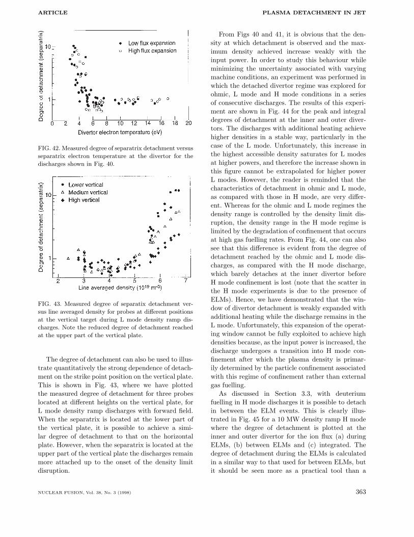
ARTICLE PLASMA DETACHMENT IN JET
FIG. 42. Measured degree of separatrix detachment versus
separatrix electron temperature at the divertor for the
discharges shown in Fig. 40.
FIG. 43. Measured degree of separatix detachment ver-
sus line averaged density for probes at different positions
at the vertical target during L mode density ramp dis-
charges. Note the reduced degree of detachment reached
at the upper part of the vertical plate.
The degree of detachment can also be used to illus-trate quantitatively the strong dependence of detach-ment on the strike point position on the vertical plate.This is shown in Fig. 43, where we have plottedthe measured degree of detachment for three probeslocated at different heights on the vertical plate, forL mode density ramp discharges with forward field.When the separatrix is located at the lower part ofthe vertical plate, it is possible to achieve a simi-lar degree of detachment to that on the horizontalplate. However, when the separatrix is located at theupper part of the vertical plate the discharges remainmore attached up to the onset of the density limitdisruption.
From Figs 40 and 41, it is obvious that the den-sity at which detachment is observed and the max-imum density achieved increase weakly with theinput power. In order to study this behaviour whileminimizing the uncertainty associated with varyingmachine conditions, an experiment was performed inwhich the detached divertor regime was explored forohmic, L mode and H mode conditions in a seriesof consecutive discharges. The results of this experi-ment are shown in Fig. 44 for the peak and integraldegrees of detachment at the inner and outer diver-tors. The discharges with additional heating achievehigher densities in a stable way, particularly in thecase of the L mode. Unfortunately, this increase inthe highest accessible density saturates for L modesat higher powers, and therefore the increase shown inthis figure cannot be extrapolated for higher powerL modes. However, the reader is reminded that thecharacteristics of detachment in ohmic and L mode,as compared with those in H mode, are very differ-ent. Whereas for the ohmic and L mode regimes thedensity range is controlled by the density limit dis-ruption, the density range in the H mode regime islimited by the degradation of confinement that occursat high gas fuelling rates. From Fig. 44, one can alsosee that this difference is evident from the degree ofdetachment reached by the ohmic and L mode dis-charges, as compared with the H mode discharge,which barely detaches at the inner divertor beforeH mode confinement is lost (note that the scatter inthe H mode experiments is due to the presence ofELMs). Hence, we have demonstrated that the win-dow of divertor detachment is weakly expanded withadditional heating while the discharge remains in theL mode. Unfortunately, this expansion of the operat-ing window cannot be fully exploited to achieve highdensities because, as the input power is increased, thedischarge undergoes a transition into H mode con-finement after which the plasma density is primar-ily determined by the particle confinement associatedwith this regime of confinement rather than externalgas fuelling.
As discussed in Section 3.3, with deuteriumfuelling in H mode discharges it is possible to detachin between the ELM events. This is clearly illus-trated in Fig. 45 for a 10 MW density ramp H modewhere the degree of detachment is plotted at theinner and outer divertor for the ion flux (a) duringELMs, (b) between ELMs and (c) integrated. Thedegree of detachment during the ELMs is calculatedin a similar way to that used for between ELMs, butit should be seen more as a practical tool than a
NUCLEAR FUSION, Vol. 38, No. 3 (1998) 363

A. LOARTE et al.
FIG. 44. Measured degree of detachment versus line averaged density at several
levels of input power (ohmic, L mode 3.5 MW and H mode 7 MW). Note the
larger densities achieved with higher input power and the lower degree of
detachment for the same density, with increasing input power. The scatter in
the H mode points is due to ELMs.
physical characteristic of divertor detachment. Thefact that the DOD during an ELM reaches valuessignificantly greater than 1 reflects the fact thatthe ELM amplitude increases more weakly thanthe square of the line averaged density. The physi-cal mechanism responsible for this behaviour is theincrease of the ELM frequency with gas fuelling rate,which makes the ELMs smaller, albeit at higher fre-quency.
One can clearly see that a large DOD can beobtained in between the ELM events (particularly atthe inner divertor) but that the integral is reducedby significantly less. During the ELM events thereis no preferential reduction in the ion flux at theinner divertor and this is because the reductionin ELM amplitude is mainly associated with theincreased ELM frequency rather than detachment.With increasing D2 fuelling the H mode confinementis degraded and divertor detachment is eventuallyobserved. This is illustrated in Fig. 46, where the con-finement is shown to deteriorate with increasing den-sity and finally detachment occurs for enhancementfactors of less than 1.3. Ultimately, this loss of con-finement dictates the maximum attainable density inH mode to values typically below that of the Green-wald limit [57], as shown in Fig. 47. The confinementloss may be due to the increase of neutral pressure
in the main chamber (Fig. 48), which has been previ-ously shown to adversely affect H mode performance[16, 56]. Together with Figs 46 and 47 the interde-pendence of detachment, energy confinement, mainchamber neutral pressure and density limit in H modedischarges is shown. While it is obvious that all fourfactors are linked, it is not clear, at present, which isthe one that drives the observed phenomena.
Similarly, we have used the degree of detach-ment definition to illustrate the benefit in terms ofdetachment of several impurity seeded H modes com-pared with the corresponding gas puffed discharges.In Fig. 49, we have plotted the degree of detach-ment achieved versus confinement time (normalizedto the ITER H-89P scaling) for a series of H mode dis-charges (cryopump on) where several impurity specieshave been injected. It is clear that puffing nitrogenleads to a larger degree of detachment while main-taining a better confinement than discharges in whichonly deuterium is puffed, although at the expense ofan increased impurity content in the main plasma.Neon seeding does not have any major advantagewith respect to deuterium puffing or nitrogen, whichis probably due to the fact that it radiates more inthe main plasma than carbon and nitrogen, whichleads to a large deterioration of confinement beforedetachment can be achieved. More promising results
364 NUCLEAR FUSION, Vol. 38, No. 3 (1998)

ARTICLE PLASMA DETACHMENT IN JET
FIG. 45. (a) Measured peak degree of detachment dur-
ing ELMs and (b) between ELMs for an H mode density
scan (11 MW of NBI). Note the low degree of detach-
ment reached at the ELMs for both divertors and the
large degree of detachment reached at the inner diver-
tor between the ELMs. This is characteristic of detach-
ment in H modes, where the divertor is detached between
ELMs and reattached at the ELMs. The integral degree of
detachment (c) includes the ELMs in its calculation and
remains under 10 up to the highest densities.
have been obtained in ASDEX Upgrade using neonseeding in the completely detached H mode (CDH)regime, where good confinement and strong detach-ment are simultaneously observed [59]. Further workis required to establish why such regimes are notobtained in JET, the main difference between thetwo experiments being the observed profile peakingin ASDEX Upgrade (and in TEXTOR [78]), whichmay be characteristic of smaller machines and there-fore not seen in JET.
In vertical plate L mode discharges with reversedfield the outer divertor is very resistant to detach-ment. This makes the final state reached by theplasma more asymmetric for reversed field verticalplate L modes than comparable discharges with for-
FIG. 46. Measured integral degree of detachment versus
energy confinement (normalized to the ITER 89-P L mode
scaling) for the H mode density scan of Fig. 45. With
increasing density the energy confinement deteriorates,
finally reaching values close to L mode at the highest
detachment.
ward field. Figure 50 shows the degree of peak detach-ment for L mode discharges with the strike zone atthe lower part of the target and with forward andreversed fields. The range of stable operation is sim-ilar for both directions of the field but the degree ofdetachment reached, in particular at the outer diver-tor, is much smaller for discharges with reversed field.For this reason, the experiments with the reversedtoroidal field were not pursued further, as they do notprovide any benefit with respect to the achievementof detachment compared with those with forward fieldand have a significantly higher H mode threshold.
The effect of configuration on detachment has alsobeen explored for discharges with reversed toroidalfield in the ohmic and L mode (4 MW of NBI)regimes, as shown in Fig. 51. An increase in thedetachment window with additional heating is alsofound for discharges with reversed field and it is par-ticularly large for vertical plate divertor discharges.However, it is also important to note that the degreeof detachment achieved for the peak ion flux is verysmall in this case, particularly for the outer diver-tor, which shows again the problem of the unstableapproach to detachment for reversed field dischargesalready discussed above.
NUCLEAR FUSION, Vol. 38, No. 3 (1998) 365

A. LOARTE et al.
FIG. 47. Measured integral degree of detachment ver-
sus plasma density (normalized to the Greenwald value)
for the H mode density scan of Fig. 45. As the den-
sity approaches the Greenwald value, the degree of
detachment increases and confinement deteriorates (see
Fig. 46).
FIG. 48. Measured integral degree of detachment versus
main chamber neutral pressure for the H mode density
scan of Fig. 45. With increasing degree of detachment the
neutral pressure in the main chamber increases.
FIG. 49. Inner divertor integral degree of detachment for
a series of H mode discharges (11 MW of NBI) with deu-
terium puffing alone and with neon and nitrogen seeding
versus energy confinement (normalized to the ITER 89-P
scaling). Note the larger degree of detachment achieved
for discharges with nitrogen seeding, while maintaining
an improved confinement. This behaviour is not observed
with neon seeding, which is probably related to the tem-
perature dependence of its radiation efficiency.
FIG. 50. Measured degree of peak detachment versus line
averaged density for L mode discharges on the vertical
target and forward and reversed fields. The range of den-
sities achieved in a stable way is similar for both direc-
tions of the field but the degree of detachment obtained
at the outer divertor is much smaller for reversed field
discharges.
366 NUCLEAR FUSION, Vol. 38, No. 3 (1998)

ARTICLE PLASMA DETACHMENT IN JET
FIG. 51. Measured degree of peak detachment versus
line averaged density for ohmic and L mode (4 MW of
NBI) discharges with reversed field and several divertor
configurations. The detachment window is widened with
the additional power (particularly for vertical plate dis-
charges). However, the degree of detachment obtained at
the outer divertor is very small for L mode discharges.
7. CONCLUSIONS
In this article, we have presented results from dedi-cated experiments carried out to characterize plasmadetachment in the JET Mark I divertor. New andenhanced diagnostic systems have provided detailedmeasurements of core, SOL and divertor plasmaparameters on the approach to detachment. Exper-iments have been carried out to assess the rangeover which divertor detachment is observed in ohmic,L mode and ELMy H mode confinement regimes. Inaddition, the effects of additional parameters are con-sidered, including the divertor configuration, direc-tion of the toroidal field, divertor target material andinfluence of active pumping. Finally, the concept ofthe ‘degree of detachment’ is introduced as a quanti-tative means of comparing the results from the wholerange of experiments described above.
During ohmic discharges in which the density isincreased by gas fuelling, it is observed that thedivertor exhibits the three characteristic phases of
low recycling, high recycling and detachment. Thelow recycling phase is shown to be characterized bysmall parallel temperature and density gradients thatincrease as the high recycling regime is accessed. Theratio of the total ion flux and the total Dα emissionfrom the divertor is approximately 20 and in goodagreement with the calculated Johnson–Hinnov fac-tor. As the divertor electron temperature approaches5 eV, firstly at the inner divertor, the ion flux ‘rollsover’ and begins to decrease, indicating the onset ofdetachment. During this phase, it is observed that theparallel electron pressure is no longer conserved inthe SOL. Throughout the transition from low to highrecycling and detachment, it is shown that the SOLbroadens considerably, highlighting the importance ofproviding sufficient clearance between the separatrixand the vessel walls. The degree and spatial extent ofthe detachment reached in the experiment (as deter-mined from the divertor ion flux profiles) show thatthe inner divertor is completely detached while theouter divertor is only partially detached. These mea-surements have also allowed enhanced perpendiculartransport to be eliminated as the mechanism thataccounts for the reduction in parallel ion flux duringdetachment. While the divertor ion flux is observed todecrease during detachment, the divertor Dα emissionand subdivertor neutral pressure continue to increase.In principle, these seemingly contradictory observa-tions can be partially reconciled with the model pro-posed by Stangeby [33] in which the plasma momen-tum is removed by charge exchange collisions withrecycling neutrals. It is also shown that the decreasein the number of ionizations per Dα photon at theouter divertor may be explained by the change in theJohnson–Hinnov factor resulting from the decreasein divertor electron temperature and density dur-ing detachment. However, the order of magnitudedecrease in the total ion flux at the inner divertorcannot be reconciled in this way, and additional pro-cesses such as volume recombination must be invoked.Other experimental evidence, such as changes in theDγ/Dα ratio, are consistent with volume recombina-tion processes taking place [18, 43, 45]. During thefinal stages of detachment, the ionization front andpeak radiation emission are observed to migrate awayfrom the target to the X point region.
Similar general trends for detachment are observedduring density ramp experiments in L mode NBI dis-charges. During these discharges, the onset of detach-ment and the density limit occur at higher mainplasma density than comparable ohmic cases. Unfor-tunately, this trend is weaker than simple scalings
NUCLEAR FUSION, Vol. 38, No. 3 (1998) 367

A. LOARTE et al.
based on√Pinput, since the divertor radiative losses
increase at higher input powers. The total radia-tion level at which detachment begins in ohmic andL mode discharges is typically 50 to 60%, of whicharound 50% of the power entering the SOL is radi-ated in the divertor region. Stable detachment can beobtained in L mode discharges, and feedback controlof the gas fuelling using the divertor ion flux mea-surements has been successfully demonstrated. Onedistinctive feature of L mode detached discharges isthe occurrence of the so-called divertor oscillations,which are observed as large amplitude variations inthe divertor ion flux during the approach to detach-ment. This complicated phenomenon also affects thetemperature and density profiles in the outer regionof the core plasma and it is proposed that impurityproduction at the divertor target, coupled with thestability of the MARFE position, control these oscil-lations.
Owing to the presence of ELMs, the general char-acter of H mode discharges is different from ohmicand L mode discharges. As gas fuelling is increasedin H mode discharges, the ELMs decrease in ampli-tude and increase in frequency. Beyond certain lev-els of gas fuelling, the confinement deteriorates andthis ultimately limits the maximum density and radi-ated power fraction (50%) that can be attained inH mode. Nevertheless, similar detachment behaviourof the ion flux and the Dα emission is observed, albeitbetween ELM events. During the ELM event, detach-ment is not sustained and large ion fluxes are mea-sured at the divertor target, although the divertorDα emission may actually decrease. These so-called‘negative’ ELMs may be understood by taking intoaccount changes of the divertor electron temperatureresulting from the energy pulse associated with theELM.
Detailed experiments have been carried out toassess the influence of divertor geometry and wallclearance on plasma detachment. It is shown thatohmic discharges with low wall clearance have lowerthreshold densities for detachment and density limitby about 35%. This result can be related to the rel-ative proportions of bulk and divertor plasma radi-ation, for which the fraction of bulk radiation issignificantly higher in the low wall clearance dis-charges. Experiments to assess the effect of divertorflux expansion for discharges with the strike zoneson the horizontal targets are complicated by the wallclearance issue. In the case of the high flux expan-sion configuration, the wall clearance is reduced andlowers both the threshold density for detachment and
the density limit by the same degree as observed forexperiments in which the wall clearance is reducedindependently of the flux expansion. These observa-tions lead to the conclusion that the wall clearancemay be the dominant effect in these experimentsrather than the flux expansion. Similar behaviouris observed during L mode discharges although theinfluence of wall clearance was found to be muchweaker.
In the JET Mark I divertor configuration, it ispossible to operate with the strike zones located oneither the horizontal or vertical target plates, andexperiments have been carried out to assess the rel-ative merits of these configurations. In contrast topredictions from 2-D modelling codes, there were nosignificant differences between the onset of detach-ment and the density limit for the two configura-tions. Detailed comparison of the ion flux profiles forthe vertical target case shows that the detachmentoccurs more simultaneously for the inner and outerdivertors and that the degree of detachment is largerat the lower part of the vertical plate. It should, how-ever, be stressed that the degree of detachment onany part of the vertical plate is never larger thanthat for the horizontal target. There is some evi-dence that the presence of neutral bypass leaks andthe existence of an inward SOL particle pinch mayyet account for the discrepancies between code andexperiment.
Dedicated experiments have been carried out toassess the effect of the toroidal field on the detach-ment behaviour in JET. It was expected that, owingto the more symmetric divertor plasma parametersin reversed field discharges, the onset of detachmentshould occur over a smaller density range for the innerand outer divertors. This has only been confirmedfor one divertor configuration, while it seems to pro-duce the opposite effect on the other configurations.Regardless of divertor configuration, almost immedi-ately after detachment, the reversed field dischargesform a MARFE in the main plasma, which producesa density limit. The levels of radiated power are sim-ilar for both forward and reversed field, so that thisbehaviour cannot be explained by increased impu-rity contamination. Therefore, in the case of L modereversed field discharges, it was also not possible toobtain steady state detached plasmas.
By using the cryopump installed in the JET Mark Idivertor, the influence of active pumping on detachedplasmas has been studied. It was found that the over-all density threshold for detachment and the densitylimit are similar with and without active pumping.
368 NUCLEAR FUSION, Vol. 38, No. 3 (1998)
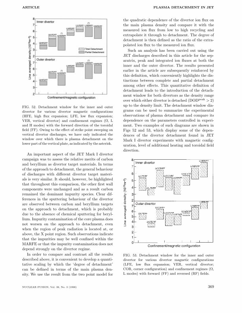
ARTICLE PLASMA DETACHMENT IN JET
FIG. 52. Detachment window for the inner and outer
divertor for various divertor magnetic configurations
(HFE, high flux expansion; LFE, low flux expansion;
VER, vertical divertor) and confinement regimes (Ω, L
and H modes) with the forward direction of the toroidal
field (FF). Owing to the effect of strike point sweeping on
vertical divertor discharges, we have only indicated the
window over which there is plasma detachment on the
lower part of the vertical plate, as indicated by the asterisk.
An important aspect of the JET Mark I divertorcampaign was to assess the relative merits of carbonand beryllium as divertor target materials. In termsof the approach to detachment, the general behaviourof discharges with different divertor target materi-als is very similar. It should, however, be highlightedthat throughout this comparison, the other first wallcomponents were unchanged and as a result carbonremained the dominant impurity species. Clear dif-ferences in the sputtering behaviour of the divertorare observed between carbon and beryllium targetson the approach to detachment, which is probablydue to the absence of chemical sputtering for beryl-lium. Impurity contamination of the core plasma doesnot worsen on the approach to detachment, evenwhen the region of peak radiation is located at, orabove, the X point region. Such observations indicatethat the impurities may be well confined within theMARFE or that the impurity contamination does notdepend strongly on the divertor regime.
In order to compare and contrast all the resultsdescribed above, it is convenient to develop a quanti-tative scaling by which the ‘degree of detachment’can be defined in terms of the main plasma den-sity. We use the result from the two point model for
the quadratic dependence of the divertor ion flux onthe main plasma density and compare it with themeasured ion flux from low to high recycling andextrapolate it through to detachment. The degree ofdetachment is then defined as the ratio of the extra-polated ion flux to the measured ion flux.
Such an analysis has been carried out using theJET discharges described in this article for the sep-aratrix, peak and integrated ion fluxes at both theinner and the outer divertor. The results presentedearlier in the article are subsequently reinforced bythis definition, which conveniently highlights the dis-tinctions between complete and partial detachmentamong other effects. This quantitative definition ofdetachment leads to the introduction of the detach-ment window for both divertors as the density rangeover which either divertor is detached (DODpeak > 2)up to the density limit. The detachment window dia-grams can be used to summarize the experimentalobservations of plasma detachment and compare itsdependence on the parameters controlled in experi-ment. Two examples of such diagrams are shown inFigs 52 and 53, which display some of the depen-dences of the divertor detachment found in JETMark I divertor experiments with magnetic config-uration, level of additional heating and toroidal fielddirection.
FIG. 53. Detachment window for the inner and outer
divertor for various divertor magnetic configurations
(LFE, low flux expansion; VER, vertical divertor;
COR, corner configuration) and confinement regimes (Ω,
L modes) with forward (FF) and reversed (RF) fields.
NUCLEAR FUSION, Vol. 38, No. 3 (1998) 369

A. LOARTE et al.
Finally, we propose the quantitative frameworkoffered by the definition of the ‘degree of detachment’as a tool for comparing experiments from differentdivertor tokamaks.
ACKNOWLEDGEMENTS
It is a pleasure to acknowledge the contributionsfrom many members of the JET Divertor Task Forceand the JET Team to this paper. We are particularlygrateful to P.C. Stangeby, K. Borrass, A. Taroni, R.Simonini, J. de Haas, Y. Ul’Haq, A. Rookes, L. Porteand A. Tabasso for contributing experimental dataand/or fruitful discussions. One of the authors (A.L.)wishes to acknowledge helpful discussions with mem-bers of other divertor tokamak experiments and ITERDivertor Experts groups.
REFERENCES
[1] REBUT, P.H., et al., Fusion Eng. Des. 22 (1993) 7.
[2] JANESCHITZ, G., et al., J. Nucl. Mater. 220–222
(1995) 73.
[3] WATKINS, M.L., REBUT, P.H., in 1992 Interna-
tional Conference on Plasma Physics (Proc. Conf.
Innsbruck, 1992), Vol. 16C, Part II, European Phys-
ical Society, Geneva (1992) 731.
[4] BORRASS, K., JANESCHITZ, G., Nucl. Fusion 34
(1994) 1203.
[5] CLEMENT, S., et al., Bull. Am. Phys. Soc. (1991)
(Rep. JET-IR(91)11, JET Joint Undertaking, Abing-
don (1991)).
[6] PETRIE, T., et al., J. Nucl. Mater. 196–198 (1992)
848.
[7] JANESCHITZ, G., et al., in 1992 International Con-
ference on Plasma Physics (Proc. Conf. Innsbruck,
1992), Vol. 16C, Part II, European Physical Society,
Geneva (1992) 727.
[8] ASDEX - Upgrade Results and Conference Contribu-
tions, Periods 6/92–9/93, IPP Rep. IPP-5-54, Max-
Planck-Institut fur Plasmaphysik, Garching (1993).
[9] LIPSCHULTZ, B., et al., J. Nucl. Mater. 220–222
(1995) 50.
[10] JET TEAM (presented by L.D. HORTON), in
Plasma Physics and Controlled Nuclear Fusion
Research 1994 (Proc. 15th Int. Conf. Seville, 1994),
Vol. 1, IAEA, Vienna (1995) 541.
[11] MATTHEWS, G.F., JET TEAM, Plasma Phys.
Control. Fusion 37A (1995) 227.
[12] HOSOGANE, N., et al., J. Nucl. Mater. 220–222
(1995) 420.
[13] JET TEAM (presented by D.J. CAMPBELL), in
Plasma Physics and Controlled Nuclear Fusion
Research 1994 (Proc. 15th Int. Conf. Seville, 1994),
Vol. 1, IAEA, Vienna (1995) 527.
[14] KEILHACKER, M., JET TEAM, Plasma Phys.
Control. Fusion 37A (1995) 3.
[15] SARTORI, R., et al., in Controlled Fusion
and Plasma Physics (Proc. 22nd Eur. Conf.
Bournemouth, 1995), Vol. 19C, Part IV, European
Physical Society, Geneva (1995) 141.
[16] SAIBENE, G., et al., ibid., Part II, p. 121.
[17] BOHM, D., in The Characteristics of Electrical
Discharges in Magnetic Fields (GUTHRIE, A.,
WAKERLING, R.K., Eds), McGraw-Hill, New York
(1949).
[18] LOARTE, A., J. Nucl. Mater. 241–243 (1997) 118.
[19] ASAKURA, N., et al., J. Nucl. Mater. 241–243
(1997) 559.
[20] SHIMOMURA, Y., et al., Nucl. Fusion 23 (1983)
869.
[21] HARBOUR, P.J., et al., J. Nucl. Mater. 196–198
(1992) 386.
[22] LaBOMBARD, B., et al., Phys. Plasmas 2 (1995)
2242.
[23] JOHNSON, L., HINNOV, E., J. Quant. Spectrosc.
Radiat. Transfer 13 (1973) 333.
[24] CHANKIN, A.V., et al., Plasma Phys. Control.
Fusion 36 (1994) 1853.
[25] HUTCHINSON, I.H., et al., Plasma Phys. Control.
Fusion 37 (1995) 1389.
[26] LaBOMBARD, B., et al., J. Nucl. Mater. 241–243
(1997) 149.
[27] PORTER, G.D., et al., Phys. Plasmas 3 (1996) 1967.
[28] PETRIE, T., et al., J. Nucl. Mater. 241–243 (1997)
639.
[29] MONK, R.D., et al., in Controlled Fusion and
Plasma Physics (Proc. 22nd Eur. Conf.
Bournemouth, 1995), Vol. 19C, Part III, European
Physical Society, Geneva (1995) 293.
[30] MONK, R.D., et al., J. Nucl. Mater. 241–243 (1997)
396.
[31] LIPSCHULTZ, B., et al., Nucl. Fusion 24 (1984) 977.
[32] SCHMITZ, L., et al., Phys. Plasmas 2 (1995) 3081.
[33] STANGEBY, P.C., Nucl. Fusion 33 (1993) 1695.
[34] BORRASS, K., STANGEBY, P.C., in Controlled
Fusion and Plasma Physics (Proc. 20th Eur. Conf.
Lisbon, 1993), Vol. 17C, Part II, European Physical
Society, Geneva (1993) 763.
[35] MONK, R.D., et al., Contrib. Plasma Phys. 36
(1996) 37.
[36] GUENTHER, K., et al., J. Nucl. Mater. 176&177
(1990) 236.
[37] GUENTHER, K., in Controlled Fusion and Plasma
Physics (Proc. 22nd Eur. Conf. Bournemouth, 1995),
Vol. 19C, Part I, European Physical Society, Geneva
(1995) 433.
370 NUCLEAR FUSION, Vol. 38, No. 3 (1998)
ARTICLE PLASMA DETACHMENT IN JET
[38] DAVIES, S.J., et al., J. Nucl. Mater. 241–243 (1997)
426.
[39] BROSDA, B., PhD Thesis, Ruhr-Universitat,
Bochum (1993).
[40] GHENDRIH, P., Phys. Plasmas 1 (1994) 1929.
[41] SUMMERS, H.P., ADAS Users Manual, Rep. JET-
IR(94)06, JET Joint Undertaking, Abingdon (1994).
[42] POST, D., J. Nucl. Mater. 220–222 (1995) 143.
[43] LUMMA, D., TERRY, J.L., LIPSCHULTZ, B.,
Phys. Plasmas 4 (1997) 2555.
[44] TERRY, J.L., et al., in Controlled Fusion and
Plasma Physics (Proc. 24th Eur. Conf. Berchtes-
gaden, 1997), Vol. 21A, Part II, European Physical
Society, Geneva (1997) 573.
[45] NAPIONTEK, B., et al., ibid., Part IV, p. 1413.
[46] LOVEGROVE, T., et al., in Controlled Fusion
and Plasma Physics (Proc. 22nd Eur. Conf.
Bournemouth, 1995), Vol. 19C, Part III, European
Physical Society, Geneva (1995) 301.
[47] SAWADA, K., FUJIMOTO, T., J. Appl. Phys. 78
(1995) 2913.
[48] KNOLL, D.A., McHUGH, P.R., KRASHENIN-
NIKOV, S., Phys. Plasmas 3 (1996) 293.
[49] BORRASS, K., et al., J. Nucl. Mater. 241–243
(1997) 250.
[50] GARCIA-CORTES, I., et al., in Controlled Fusion
and Plasma Physics (Proc. 24th Eur. Conf. Berch-
tesgaden, 1997), Vol. 21A, Part I, European Physical
Society, Geneva (1997) 109.
[51] BORRASS, K., Nucl. Fusion 31 (1991) 1035.
[52] MATTHEWS, G.F., et al., J. Nucl. Mater. 241–243
(1997) 450.
[53] LAUX, M., et al., in Controlled Fusion and Plasma
Physics (Proc. 21st Eur. Conf. Montpellier, 1994),
Vol. 18B, Part II, European Physical Society, Geneva
(1994) 726.
[54] MERTENS, V., et al., Plasma Phys. Control. Fusion
36 (1994) 1307.
[55] ZOHM, H., Plasma Phys. Control. Fusion 38 (1996)
105.
[56] JET TEAM (presented by G.C. VLASES), in Fusion
Energy 1996 (Proc. 16th Int. Conf. Montreal, 1996),
Vol. 1, IAEA, Vienna (1997) 371.
[57] GREENWALD, M., et al., Nucl. Fusion 28 (1988)
2199.
[58] SAIBENE, G., et al., J. Nucl. Mater. 241–243
(1997) 476.
[59] GRUBER, O., et al., Phys. Rev. Lett. 74 (1995)
4217.
[60] LINGERTAT, J., et al., J. Nucl. Mater. 241–243
(1997) 402.
[61] GUO, H.Y., et al., J. Nucl. Mater. 241–243 (1997)
385.
[62] HILL, D.N., J. Nucl. Mater. 241–243 (1997) 182.
[63] TARONI, A., et al., J. Nucl. Mater. 220–222 (1995)
1086.
[64] LOARTE, A., et al., in Controlled Fusion and
Plasma Physics (Proc. 22nd Eur. Conf. Bourne-
mouth, 1995), Vol. 19C, Part III, European Physical
Society, Geneva (1995) 305.
[65] TARONI, A., et al., ibid., Part IV, p. 297.
[66] JET TEAM (presented by G.C. VLASES), in
Plasma Physics and Controlled Nuclear Fusion
Research 1992 (Proc. 14th Int. Conf. Wurzburg,
1992), Vol. 1, IAEA, Vienna (1993) 287.
[67] CHANKIN, A.V., et al., Plasma Phys. Control.
Fusion 38 (1996) 1579.
[68] LOARTE, A., paper presented at Technical Meet-
ing and Workshop on ITER Divertor Design, ITER-
EDA, Garching, 1994.
[69] LAUX, M., et al., in Controlled Fusion and Plasma
Physics (Proc. 22nd Eur. Conf. Bournemouth, 1995),
Vol. 19C, Part III, European Physical Society,
Geneva (1995) 97.
[70] CAMPBELL, D.J., JET TEAM, J. Nucl. Mater.
241–243 (1997) 379.
[71] MAGGI, C.F., et al., J. Nucl. Mater. 241–243
(1997) 414.
[72] MAGGI, C.F., PhD Thesis, Univ. of Strathclyde,
Glasgow (1996).
[73] McCRACKEN, G.M., et al., J. Nucl. Mater. 241–
243 (1997) 777.
[74] KASTELEWICZ, H., SCHNEIDER, R., NEUHAU-
SER, J., Plasma Phys. Control. Fusion 37 (1995)
723.
[75] KEILHACKER, M., et al., Phys. Scr. T2/2 (1982)
443.
[76] PITCHER, C.S., et al., in Controlled Fusion
and Plasma Physics (Proc. 22nd Eur. Conf.
Bournemouth, 1995), Vol. 19C, Part III, European
Physical Society, Geneva (1995) 245.
[77] BOSCH, H.-S., et al., ibid., p. 93.
[78] MESSIAEN, A.M., et al., Nucl. Fusion 36 (1996) 39.
(Manuscript received 20 February 1997Final manuscript accepted 24 October 1997)
E-mail address of A. Loarte:[email protected]
Subject classification: I0, Te; I1, Te; I2, Te
NUCLEAR FUSION, Vol. 38, No. 3 (1998) 371