Embed Size (px)
Citation preview

Preparation and General Conditions . . . . . . . . . . . . . . . . . . . . . . . . . . . . . . . . 2
Panel installation sequence procedure . . . . . . . . . . . . . . . . . . . . . . . . . . . . . . . 3
General underlayment instructions . . . . . . . . . . . . . . . . . . . . . . . . . . . . . . . . . . 3
A Eave Starter . . . . . . . . . . . . . . . . . . . . . . . . . . . . . . . . . . . . . . . . . . . . . . . . . . . . 4
B Rake Starter (Gable Rollover option) . . . . . . . . . . . . . . . . . . . . . . . . . . . . . . . . 5
C Closed Valley Assembly . . . . . . . . . . . . . . . . . . . . . . . . . . . . . . . . . . . . . . . . . . 6
D Open Valley Assembly . . . . . . . . . . . . . . . . . . . . . . . . . . . . . . . . . . . . . . . . . . . 7
E End Wall Flashing (Chimney Flashing option) . . . . . . . . . . . . . . . . . . . . . . . . 8
F Steel Shingle-Shake / Slate and Shingle Clip . . . . . . . . . . . . . . . . . . . . . . . . . 9
G Hip and Ridge Assembly (non-vented) . . . . . . . . . . . . . . . . . . . . . . . . . . . . . . 10
H Hip and Ridge Assembly (vented) . . . . . . . . . . . . . . . . . . . . . . . . . . . . . . . . . . 11
Ridge & Soffit Ventilation Requirements . . . . . . . . . . . . . . . . . . . . . . . . . . . . . 12
Roof Vent Flashing . . . . . . . . . . . . . . . . . . . . . . . . . . . . . . . . . . . . . . . . . . . . . . 13
Pipe Vent Flashing . . . . . . . . . . . . . . . . . . . . . . . . . . . . . . . . . . . . . . . . . . . . . . 14
Roof Jack . . . . . . . . . . . . . . . . . . . . . . . . . . . . . . . . . . . . . . . . . . . . . . . . . . . . . 13
J Side Wall Installation (Side wall corner, shake to shake detail) . . . . . . . . . . . 14
K Starter Strip - Steel #1063-000 (part shown on page) . . . . . . . . . . . . . . . . . . . 15
Español instrucciones . . . . . . . . . . . . . . . . . . . . . . . . . . . . . . . . . . . . . . . . . . . . 16 Parts List . . . . . . . . . . . . . . . . . . . . . . . . . . . . . . . . . . . . . . . . . . . . . . . . . . . . . . 20
DESCRIPTION PAGEDETAIL
2/01/09
InstallationGuide
Roofing That Lasts
BB
M

2
PREPARATION AND GENERAL CONDITIONS * 1 . Cartons should be stored in dry place under cover . Carry only one carton at a time and avoid having loose pieces
on the roof .
2 . Follow all workers compensation and OSHA safety guidelines .
3 . Minimum recommended roof pitch is 4/12 . Contact EDCO for recommendations on roofs with 3/12 pitch or less .
4 . Inspect all roof sheathing and framing to make sure that it is free of warping, in good condition and fastened properly .
5 . When re-roofing determine if existing roofing needs to be removed . Before installing new shakes/slate over existing shingles, remove any mouldings on fascia board, then cut back existing shingles flush with the fascia board at the eave and rake lines .
6 . A Class "A" fire rating can be achieved by covering the entire roof area with Georgia-Pacific 1/4" Dens-Deck . The Dens-Deck must be applied directly over the sheathing or existing roof and underneath the new underlayment . Shakes/slate installed directly over a synthetic underlayment or #30 felt underlayment without 1/4" Dens-Deck will achieve a Class "C" fire rating .
7 . The entire roof must be covered with an underlayment prior to installing shakes/slate . The underlayment should be selected based on climatic weather conditions and must comply with all local building codes . A #30 felt underlayment can be used with double layers at the eaves edge to a point at least 24" inside the exterior wall line, 18" on each side of the centerline along the entire length of the valley and around openings . The underlayments are to be overlapped 2" horizontally and 4" vertically . Follow local buidling codes .
8 . In weather climates that experience freezing temperatures and high winds it would be advisable to use a polymer modified bitumen ice and water shield in lieu of the bottom layer of doubled underlayment and possibly throughout the entire job . Ice and water shield is recommended for new construction as is following the manufacturer’s recommendations . Follow local building codes .
9 . Proper attic ventilation is necessary . Using ArrowLine venting hip, ridge and soffit panels are an excellent way to ventilate the attic . See page 3 for details on preparing the roof and page 11 for installing the hip and ridge vents .
10 . When walking on roof always wear soft soled shoes or foam rubber soled overshoes and stay close to the top of the shake/slate just under the butt projection where the shake/slate is closest to under support . Always avoid walking on four way interlock of the shake/slate . Recommended scaffolding methods should always be adhered to .
11 . Architects, contractors, and roofing installers must ensure that construction bylaws and building codes are complied with and approved . Before construction begins, building permits may need to be obtained from the local building department . To qualify for protection under the manufacturer’s warranty, the application instructions herein must be followed .
12 . Contact EDCO Products, Inc . for testing deails: UL 580-Uplift Resistance; UL 2218-Hail Resistance (4); FL4077-Florida Building Commission .
13 . Use OSHA approved fall protection equipment when working on any roof .
* THIS INSTALLATION MANUAL IS INTENDED TO BE A GUIDELINE FOR INSTALLING OUR ARROWLINE ROOFING PRODUCTS . EDCO PRODUCTS, INC . ASSUMES NO RESPONSIBILITY FOR LEAKS OR OTHER ROOFING DEFECTS DUE TO FAULTY APPLICATION . ARROWLINE ROOFING PRODUCTS ARE COVERED BY A LIFETIME LIMITED WARRANTY . FOR A COPY OF THE WARRANTY CALL 800 - 728 - 4010 . OR YOUR LOCAL DEALER . USE A PROFESSIONAL CONTRACTOR FOR INSTALLATION OF YOUR ARROWLINE ROOF .
8 0 0 - 7 2 8 - 4 0 1 0
3
Flush to Gable End
6
3
9
71
Shown withopening forventing
Shown withopening forventing
Flush toEave Starter
4" lap2" lap
354
3 10
23
210
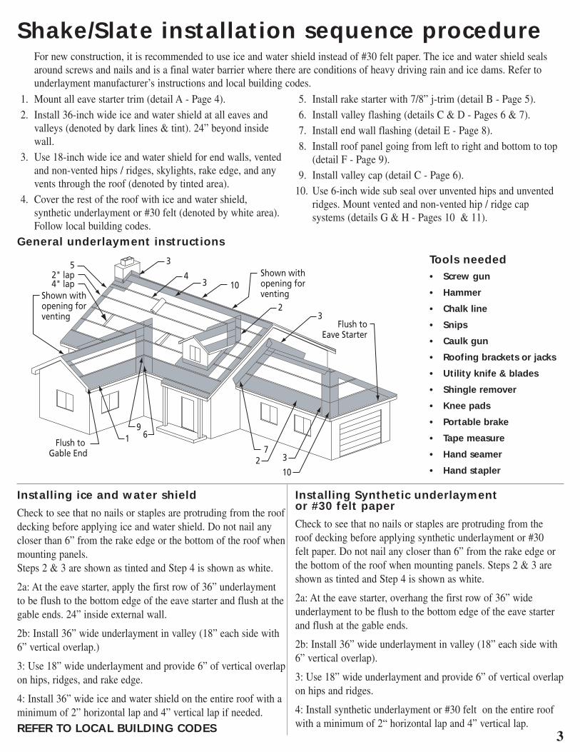
Tools needed• Screw gun
• Hammer
• Chalk line
• Snips
• Caulk gun
• Roofing brackets or jacks
• Utility knife & blades
• Shingle remover
• Knee pads
• Portable brake
• Tape measure
• Hand seamer
• Hand stapler
General underlayment instructions
Shake/Slate installation sequence procedure For new construction, it is recommended to use ice and water shield instead of #30 felt paper . The ice and water shield seals
around screws and nails and is a final water barrier where there are conditions of heavy driving rain and ice dams . Refer to underlayment manufacturer’s instructions and local building codes .
Installing ice and water shield
Check to see that no nails or staples are protruding from the roof decking before applying ice and water shield . Do not nail any closer than 6” from the rake edge or the bottom of the roof when mounting panels . Steps 2 & 3 are shown as tinted and Step 4 is shown as white .
2a: At the eave starter, apply the first row of 36” underlayment to be flush to the bottom edge of the eave starter and flush at the gable ends . 24” inside external wall .
2b: Install 36” wide underlayment in valley (18” each side with 6” vertical overlap .)
3: Use 18” wide underlayment and provide 6” of vertical overlap on hips, ridges, and rake edge .
4: Install 36” wide ice and water shield on the entire roof with a minimum of 2” horizontal lap and 4” vertical lap if needed .
REFER TO LOCAL BUILDING CODES
Installing Synthetic underlayment or #30 felt paper
Check to see that no nails or staples are protruding from the roof decking before applying synthetic underlayment or #30 felt paper . Do not nail any closer than 6” from the rake edge or the bottom of the roof when mounting panels . Steps 2 & 3 are shown as tinted and Step 4 is shown as white .
2a: At the eave starter, overhang the first row of 36” wide underlayment to be flush to the bottom edge of the eave starter and flush at the gable ends .
2b: Install 36” wide underlayment in valley (18” each side with 6” vertical overlap) .
3: Use 18” wide underlayment and provide 6” of vertical overlap on hips and ridges .
4: Install synthetic underlayment or #30 felt on the entire roof with a minimum of 2“ horizontal lap and 4” vertical lap .
1 . Mount all eave starter trim (detail A - Page 4) . 2 . Install 36-inch wide ice and water shield at all eaves and
valleys (denoted by dark lines & tint) . 24” beyond inside wall .
3 . Use 18-inch wide ice and water shield for end walls, vented and non-vented hips / ridges, skylights, rake edge, and any vents through the roof (denoted by tinted area) .
4 . Cover the rest of the roof with ice and water shield, synthetic underlayment or #30 felt (denoted by white area) . Follow local building codes .
5 . Install rake starter with 7/8” j-trim (detail B - Page 5) . 6 . Install valley flashing (details C & D - Pages 6 & 7) . 7 . Install end wall flashing (detail E - Page 8) . 8 . Install roof panel going from left to right and bottom to top
(detail F - Page 9) . 9 . Install valley cap (detail C - Page 6) . 10 . Use 6-inch wide sub seal over unvented hips and unvented
ridges . Mount vented and non-vented hip / ridge cap systems (details G & H - Pages 10 & 11) .

4
Eave Starter (Detail A) __________________
Shingle Clips(see p.8)
Roof Decking
Shake or Slate Panel
Underlayment / Ice & Water ShieldFlush to Eave Starter
Fasten every 12" o.c.
Fastener 16" o.c. after gutters and/or fascia is installed
Fascia
Eave Starter
Fasteners as required
Fascia Board
Field form
to roof pitch
Eave Starteroverlap 2"
Wrap Eave Starter around cornerand under Rake Starter
Rake Starteroverlap 2"
Rake Starterover underlaymentUnderlayment
7/8" J-Trim
7/8" J-Trim
Notch top leg 2" back andslip outside of upper J-Trim
Determine the roof pitch and bend the eave starter to the correct angle using a 10’ brake. Install eave starter at all eaves. Fasten eave starter with #10 x 1” long galvanized zip screws 12” o.c. Screw length is to be long enough to penetrate the decking.
Underlayment is to be installed over the eave starter.
Do not walk on the butt or thebottom 1/3 of the panel.
Walk on the center or upper part ofthe panel to help minimize damage.
When installing roofing panels take care to avoid walking on the butt of the panels. It is recommended that you walk on the middle part of the panel. (See illustration to the right.)

5
LT Rollover Tool
Rake Starter (Detail B) __________________
GABLE ROLLOVER OPTION FOR SHAKE PANELS
Fascia
Fastener
Fascia Board
Rake Starter
Fastener 16" o.c. after guttersand/or fascia are installed
Fastener 16" o.c.
Ice & Water Shield18" wide
Roof Decking
Underlayment
7/8" J-Trim
3/4" Field NotchShake or Slate Panel
Shingle-Shake Fastener 16" o.c.
Ice & Water ShieldForm shingle end 180°
7/8" Overhang
Fastener face nail 16 o.c.(optional)
Eave Starter
FasciaSoffit
EaveStarterEave Starter
Shake or Slate Panel
Leave Shingle extended over Eave Starter by 7/8" for bending
Have the shake or slate overhang the eave starter by 7/8” and cut to length . Notch the top leg of the shingle back 7/8” . Then form the shingle overhang around with the LT Shingle Former .
Install Rake Starter with 2” of overlap going up the rake edge and over the underlayment . Fasten with #10 x 1" galvanized zip screws or ring shank nails . Mount 7/8” j-trim going up the roof and notch back 2” on lower j-trim and slip the upper j-trim inside when progressing up the rake edge . Cut a 3/4" notch on the bottom butt edge of the panel that extends into the j-trim to create a weep hole on each course . This will allow any moisture to seep out at the overhang .
Shingle-Shakeon roof
Eave Starter
Step 6 : Hand form 180° hem
Step 2: Slip rollover tool onto shingle
Step 3: Hold down on hinged plate
Step 4: Lift and rotate handle 90°
Step 5: Rotate rollover tool 120° and remove tool
6
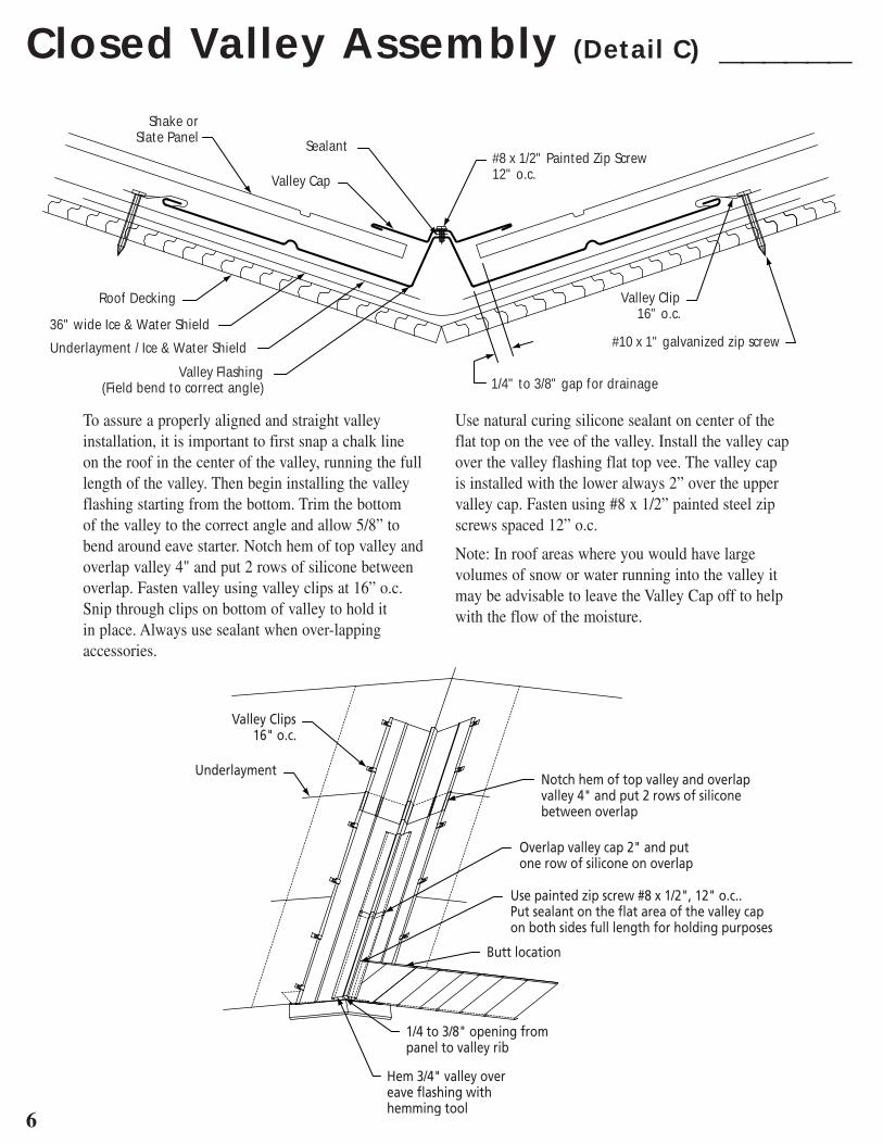
Closed Valley Assembly (Detail C) ______
To assure a properly aligned and straight valley installation, it is important to first snap a chalk line on the roof in the center of the valley, running the full length of the valley . Then begin installing the valley flashing starting from the bottom . Trim the bottom of the valley to the correct angle and allow 5/8” to bend around eave starter . Notch hem of top valley and overlap valley 4" and put 2 rows of silicone between overlap . Fasten valley using valley clips at 16” o .c . Snip through clips on bottom of valley to hold it in place . Always use sealant when over-lapping accessories .
Use natural curing silicone sealant on center of the flat top on the vee of the valley . Install the valley cap over the valley flashing flat top vee . The valley cap is installed with the lower always 2” over the upper valley cap . Fasten using #8 x 1/2” painted steel zip screws spaced 12” o .c .
Note: In roof areas where you would have large volumes of snow or water running into the valley it may be advisable to leave the Valley Cap off to help with the flow of the moisture .
Roof Decking
36" wide Ice & Water Shield
Underlayment / Ice & Water Shield
Valley Flashing(Field bend to correct angle)
Valley Clip16" o.c.
#10 x 1" galvanized zip screw
1/4" to 3/8" gap for drainage
Shake orSlate Panel
Valley Cap
Sealant#8 x 1/2" Painted Zip Screw12" o.c.
Valley Clips16" o.c.
UnderlaymentNotch hem of top valley and overlapvalley 4" and put 2 rows of siliconebetween overlap
Overlap valley cap 2" and put one row of silicone on overlap
Use painted zip screw #8 x 1/2", 12" o.c.. Put sealant on the flat area of the valley capon both sides full length for holding purposes
Butt location
1/4 to 3/8" opening from panel to valley rib
Hem 3/4" valley over eave flashing with hemming tool
7
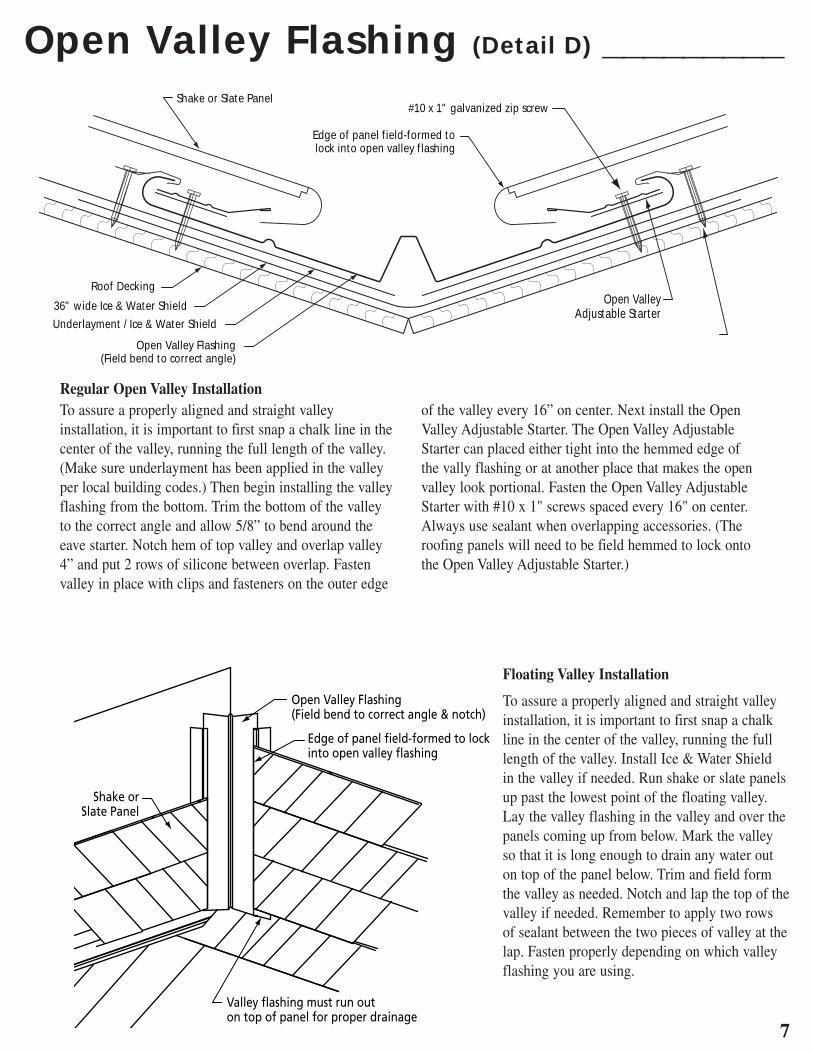
Open Valley Flashing (Detail D) _________
Regular Open Valley InstallationTo assure a properly aligned and straight valley installation, it is important to first snap a chalk line in the center of the valley, running the full length of the valley . (Make sure underlayment has been applied in the valley per local building codes .) Then begin installing the valley flashing from the bottom . Trim the bottom of the valley to the correct angle and allow 5/8” to bend around the eave starter . Notch hem of top valley and overlap valley 4” and put 2 rows of silicone between overlap . Fasten valley in place with clips and fasteners on the outer edge
of the valley every 16” on center . Next install the Open Valley Adjustable Starter . The Open Valley Adjustable Starter can placed either tight into the hemmed edge of the vally flashing or at another place that makes the open valley look portional . Fasten the Open Valley Adjustable Starter with #10 x 1" screws spaced every 16" on center . Always use sealant when overlapping accessories . (The roofing panels will need to be field hemmed to lock onto the Open Valley Adjustable Starter .)
Floating Valley Installation
To assure a properly aligned and straight valley installation, it is important to first snap a chalk line in the center of the valley, running the full length of the valley . Install Ice & Water Shield in the valley if needed . Run shake or slate panels up past the lowest point of the floating valley . Lay the valley flashing in the valley and over the panels coming up from below . Mark the valley so that it is long enough to drain any water out on top of the panel below . Trim and field form the valley as needed . Notch and lap the top of the valley if needed . Remember to apply two rows of sealant between the two pieces of valley at the lap . Fasten properly depending on which valley flashing you are using .
Edge of panel field-formed tolock into open valley flashing
Shake or Slate Panel
Roof Decking
36" wide Ice & Water Shield
Underlayment / Ice & Water Shield
Open Valley Flashing(Field bend to correct angle)
Open ValleyAdjustable Starter
#10 x 1" galvanized zip screw
8
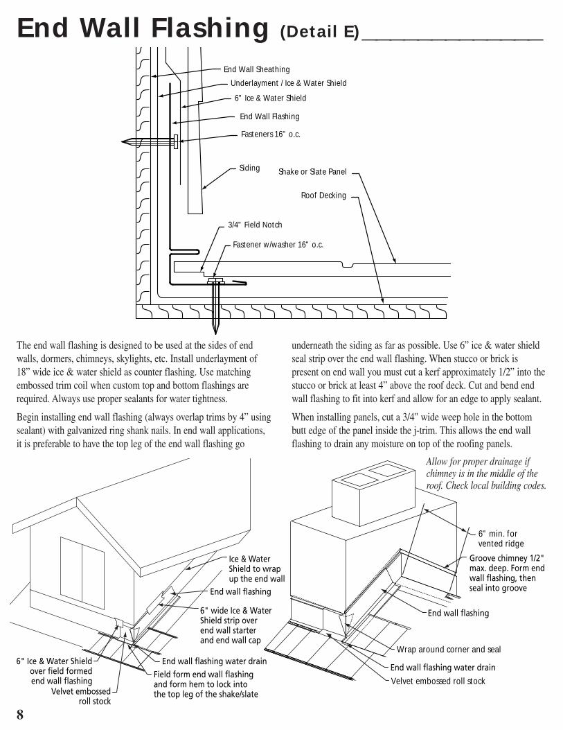
End Wall Flashing (Detail E) _____________
The end wall flashing is designed to be used at the sides of end walls, dormers, chimneys, skylights, etc . Install underlayment of 18” wide ice & water shield as counter flashing . Use matching embossed trim coil when custom top and bottom flashings are required . Always use proper sealants for water tightness .
Begin installing end wall flashing (always overlap trims by 4” using sealant) with galvanized ring shank nails . In end wall applications, it is preferable to have the top leg of the end wall flashing go
underneath the siding as far as possible . Use 6” ice & water shield seal strip over the end wall flashing . When stucco or brick is present on end wall you must cut a kerf approximately 1/2” into the stucco or brick at least 4” above the roof deck . Cut and bend end wall flashing to fit into kerf and allow for an edge to apply sealant .
When installing panels, cut a 3/4" wide weep hole in the bottom butt edge of the panel inside the j-trim . This allows the end wall flashing to drain any moisture on top of the roofing panels .
End Wall Sheathing
Underlayment / Ice & Water Shield
6" Ice & Water Shield
End Wall Flashing
Fasteners 16" o.c.
Siding
3/4" Field Notch
Fastener w/washer 16" o.c.
Shake or Slate Panel
Roof Decking
Velvet embossed roll stock
Wrap around corner and seal
6" min. for vented ridge
Allow for proper drainage if chimney is in the middle of the roof. Check local building codes.
9
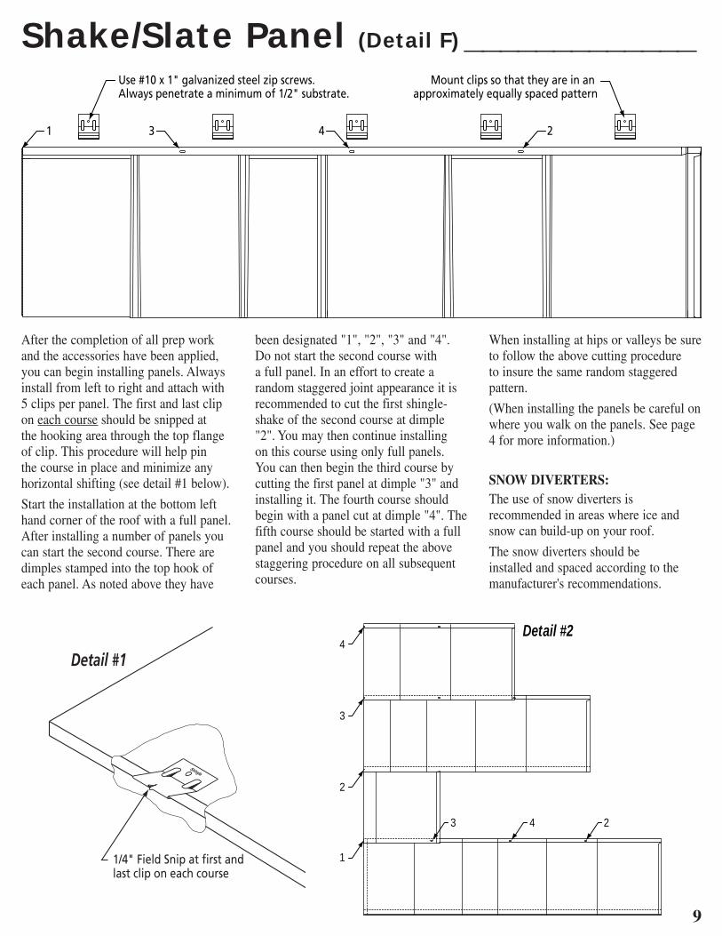
Shake/Slate Panel (Detail F) _____________
After the completion of all prep work and the accessories have been applied, you can begin installing panels . Always install from left to right and attach with 5 clips per panel . The first and last clip on each course should be snipped at the hooking area through the top flange of clip . This procedure will help pin the course in place and minimize any horizontal shifting (see detail #1 below) .
Start the installation at the bottom left hand corner of the roof with a full panel . After installing a number of panels you can start the second course . There are dimples stamped into the top hook of each panel . As noted above they have
been designated "1", "2", "3" and "4" . Do not start the second course with a full panel . In an effort to create a random staggered joint appearance it is recommended to cut the first shingle-shake of the second course at dimple "2" . You may then continue installing on this course using only full panels . You can then begin the third course by cutting the first panel at dimple "3" and installing it . The fourth course should begin with a panel cut at dimple "4" . The fifth course should be started with a full panel and you should repeat the above staggering procedure on all subsequent courses .
When installing at hips or valleys be sure to follow the above cutting procedure to insure the same random staggered pattern .
(When installing the panels be careful on where you walk on the panels . See page 4 for more information .)
SNOW DIVERTERS:The use of snow diverters is recommended in areas where ice and snow can build-up on your roof .
The snow diverters should be installed and spaced according to the manufacturer's recommendations .
4
3
3 4 2
2
1
Detail #2

10
Hip / Ridge Assembly (Detail G) _________
Cut panels to the proper length and install as close to the hip or ridgeline as possible . Cover cut edges with 6” of ice & water shield centered along the entire length of the hip or ridge edge . Bend starter base in a 10’ brake to the correct roof pitch . Install starter
base over the panels and overlap subsequent pieces approximately 4” using sealant . The hip / ridge caps should be installed over starter base with #10 x 1 1/2” steel zip screws using 2 shingle clips per hip / ridge cap .
Roof Decking
Fastener
#10 x 1 1/2" Zip ScrewUnderlayment / Ice & Water Shield
Shake or Slate Panel
Hip / Ridge CapStarter Base w/Foam Seal
6" Ice & Water Shield
Fasten starter base withwith #10 x 1 1/2" screwinto roof deck at everybutt location
Using one shingle clip per side,screw with #10 x 1 1/2" zip screw(Be sure to keep caps straightwith starter base)
Cover panelswith 6" wideice & water shield
Cut tip of hip cap away andform down, matching eave starterNext, leave 5/8" legs and form under eave starter lip
Fasten with #10 x 1 1/2" screw
6" ice & water shieldover shingles
Starter Base with foam seal
(non-vented)
11
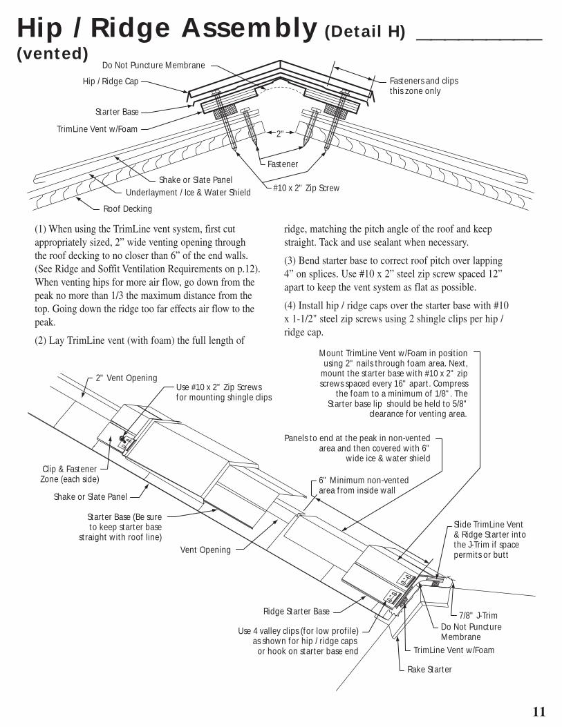
Hip / Ridge Assembly (Detail H) _________
(1) When using the TrimLine vent system, first cut appropriately sized, 2” wide venting opening through the roof decking to no closer than 6” of the end walls . (See Ridge and Soffit Ventilation Requirements on p .12) . When venting hips for more air flow, go down from the peak no more than 1/3 the maximum distance from the top . Going down the ridge too far effects air flow to the peak .
(2) Lay TrimLine vent (with foam) the full length of
ridge, matching the pitch angle of the roof and keep straight . Tack and use sealant when necessary .
(3) Bend starter base to correct roof pitch over lapping 4” on splices . Use #10 x 2” steel zip screw spaced 12” apart to keep the vent system as flat as possible .
(4) Install hip / ridge caps over the starter base with #10 x 1-1/2" steel zip screws using 2 shingle clips per hip / ridge cap .
Roof Decking
Underlayment / Ice & Water ShieldShake or Slate Panel
TrimLine Vent w/Foam
Starter Base
Hip / Ridge Cap
2"
Fastener
#10 x 2" Zip Screw
Fasteners and clipsthis zone only
Do Not Puncture Membrane
Rake Starter
TrimLine Vent w/Foam
7/8" J-TrimRidge Starter Base
Use 4 valley clips (for low profile)as shown for hip / ridge caps
or hook on starter base end
Slide TrimLine Vent & Ridge Starter into the J-Trim if space permits or butt
6" Minimum non-vented area from inside wall
Do Not Puncture Membrane
Vent Opening
Starter Base (Be sureto keep starter base
straight with roof line)
Shake or Slate Panel
2" Vent Opening
Clip & Fastener Zone (each side)
Use #10 x 2" Zip Screwsfor mounting shingle clips
Panels to end at the peak in non-ventedarea and then covered with 6"
wide ice & water shield
Mount TrimLine Vent w/Foam in position using 2" nails through foam area. Next,
mount the starter base with #10 x 2" zip screws spaced every 16" apart. Compress
the foam to a minimum of 1/8". The Starter base lip should be held to 5/8"
clearance for venting area.
(vented)

12
Ridge & Soffit Ventilation Requirements ______
Calculations are based on equal ventilation at the ridge and at the eaves . This requires a 1:300 ratio (1 square foot of ventilation to every 300 square feet of attic space) . (Check the local building codebook for exact requirements .) This calculation is for 50% at the ridge and 50% at the soffit . Note: The soffit and ridge
vent are to be at least equal to each other . The eaves are recommended to have an adder of 10% to 25%, this increases airflow pressure to the peak .
Contact an architect or your local building official if you need additional information .
Soffit
Roof Decking
Trimline Vent w/FoamHip / Ridge Cap
Use continuous ridge vents formaximum efficiency of air flow
Attic Space
AIRFLOWAIRFLOW
Calculations: using 5/8” thick Trimline Vent with 13 square inches / lineal foot of free air per foot .
1 . Calculate attic floor space 30 feet wide x 40 feet long = 1200 square feet
2 . Using 1:300 ratio net free airflow . (Total ridge and eave air flow) 1200 square feet / 300 square feet = 4 square feet
3 . Calculation for the ridge or soffits (50% min . for each) 4 square feet / 2 = 2 square feet min .
4 . Convert 1 square foot to square inches for one side 144 square inches x 2 square feet (Total for ridge or soffit) = 288 square inches per side
5 . Trimline Vent Plus 5/8” thick (13 sq . inches net free air per foot) used for ridge venting and hip venting 288 square inches / 13 = 22 .15 feet of ridge vent
AtticSq. Ft.
Sq. Inchesat Ridge
Min. Ft. of Vent
Sq. InchesSoffit Vent
1000 240 18 2401100 264 20 2641200 288 22 2881300 312 24 3121400 336 26 3361500 360 28 3601600 384 30 3841700 408 31 4081800 432 33 4321900 456 35 4562000 480 37 480
AtticSq. Ft.
Sq. Inchesat Ridge
Min. Ft. of Vent
Sq. InchesSoffit Vent
2100 504 39 5042200 528 41 5282300 552 42 5522400 576 44 5762500 600 46 6002600 624 48 6242700 648 50 6482800 672 52 6722900 696 54 6963000 720 56 720
13
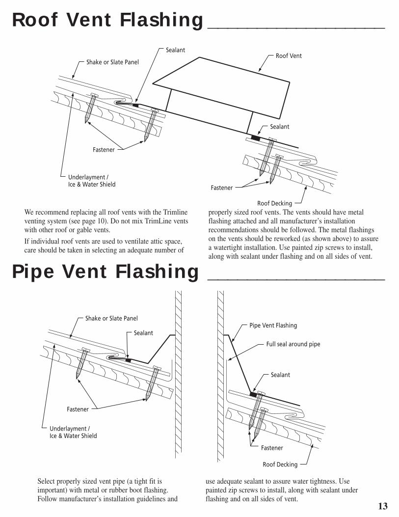
Roof Vent Flashing __________________
Pipe Vent Flashing __________________
We recommend replacing all roof vents with the Trimline venting system (see page 10) . Do not mix TrimLine vents with other roof or gable vents .
If individual roof vents are used to ventilate attic space, care should be taken in selecting an adequate number of
properly sized roof vents . The vents should have metal flashing attached and all manufacturer’s installation recommendations should be followed . The metal flashings on the vents should be reworked (as shown above) to assure a watertight installation . Use painted zip screws to install, along with sealant under flashing and on all sides of vent .
Underlayment / Ice & Water Shield
Shake or Slate PanelRoof Vent
Sealant
Sealant
Roof Decking
Fastener
Fastener
Underlayment / Ice & Water Shield
Shake or Slate PanelPipe Vent Flashing
Sealant
Sealant
Roof Decking
Fastener
Fastener
Full seal around pipe
Select properly sized vent pipe (a tight fit is important) with metal or rubber boot flashing . Follow manufacturer’s installation guidelines and
use adequate sealant to assure water tightness . Use painted zip screws to install, along with sealant under flashing and on all sides of vent .
14
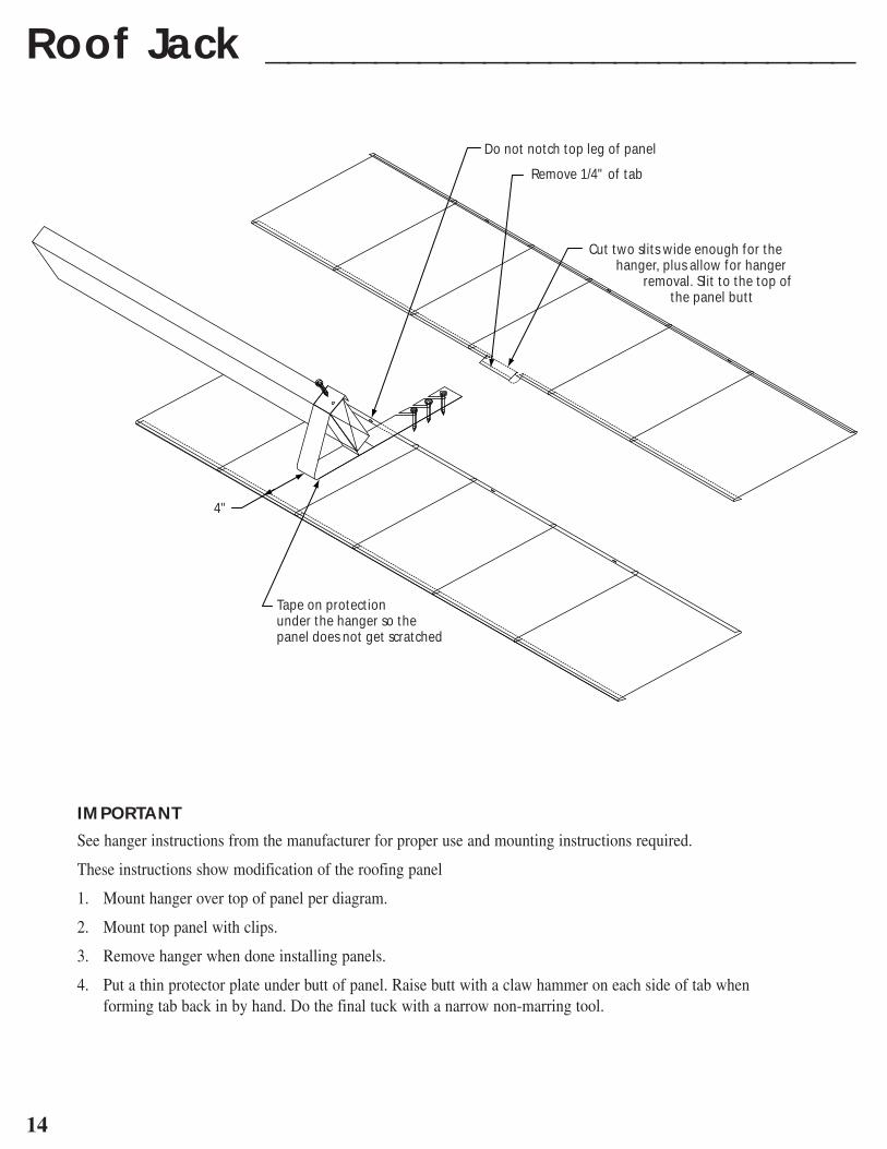
Roof Jack ___________________________
4"
Tape on protectionunder the hanger so thepanel does not get scratched
Do not notch top leg of panel
Remove 1/4" of tab
Cut two slits wide enough for the hanger, plus allow for hanger
removal. Slit to the top of the panel butt
IMPORTANT
See hanger instructions from the manufacturer for proper use and mounting instructions required .
These instructions show modification of the roofing panel
1 . Mount hanger over top of panel per diagram .
2 . Mount top panel with clips .
3 . Remove hanger when done installing panels .
4 . Put a thin protector plate under butt of panel . Raise butt with a claw hammer on each side of tab when forming tab back in by hand . Do the final tuck with a narrow non-marring tool .
15
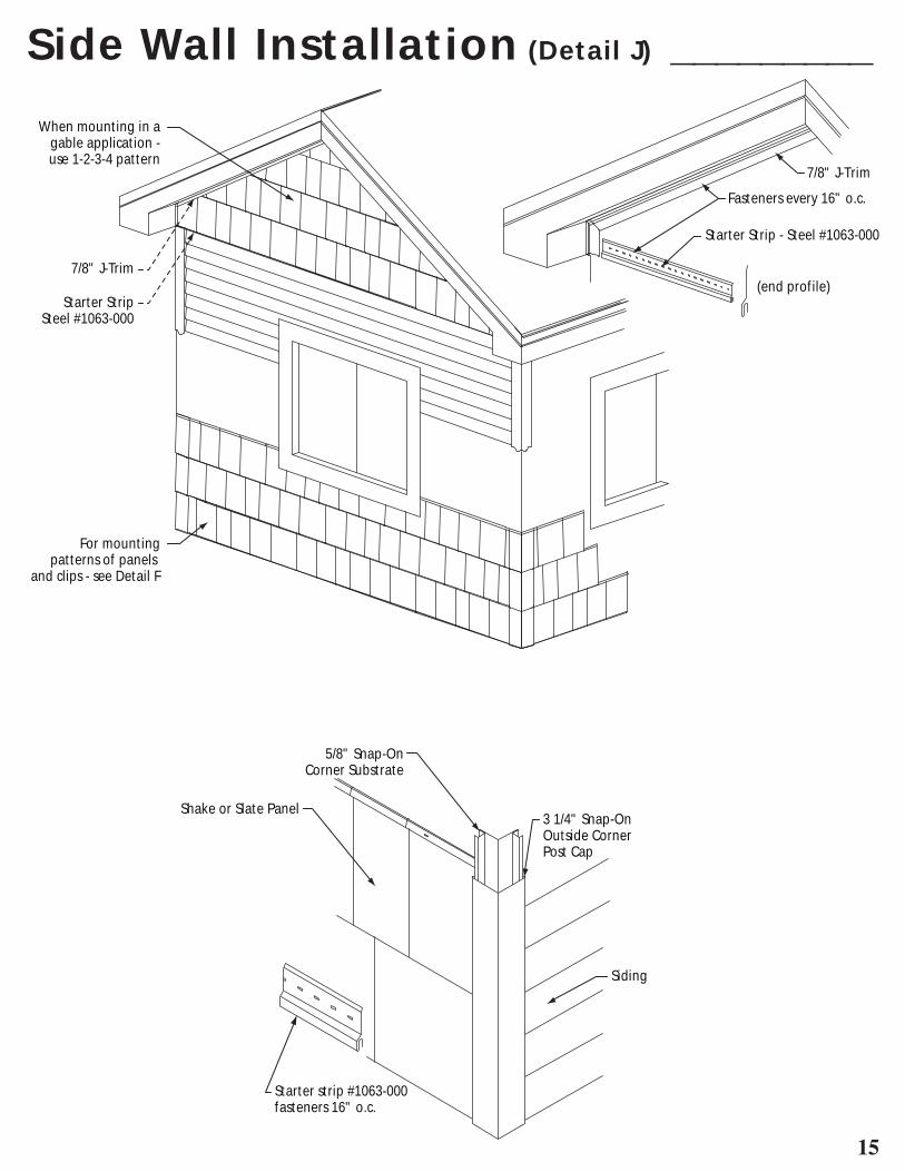
Side Wall Installation (Detail J) _________
When mounting in a gable application - use 1-2-3-4 pattern
For mounting patterns of panels
and clips - see Detail F
7/8" J-Trim
Starter StripSteel #1063-000
7/8" J-Trim
Fasteners every 16" o.c.
Starter Strip - Steel #1063-000
(end profile)
5/8" Snap-OnCorner Substrate
3 1/4" Snap-OnOutside CornerPost Cap
Shake or Slate Panel
Starter strip #1063-000fasteners 16" o.c.
Siding

16
PÁGINA 2La preparación y las condiciones generales
1 . Los cartones se deben almacenar en un sitio seco a cubierto . Lleve sólo un cartón a la vez y evite las piezas sueltas en en tejado .
2 . Siga toda compensación de trabajadores y pautas de seguridad de OSHA .
3 . Se requiere el pitch del tejado mínimo de 4/12 .
4 . Inspeccione todo roof sheathing and framing para asegurarse que es libre de alabear, en buen estado y abrochado apropriadamente .
5 . Cuando esté retechando, determine si el tejado que existe tiene que ser quitado . Antes de instalar los nuevos shingle shakes sobre las tejas existentes, quítese cualquiere amoldamiento en la tabla de fascia, luego, vuleva a cortar las tejas a nivel con la tabla fascia en el eave and rake lines .
6 . Una clase “una” de calificación del fuego puede ser lograda por cubrir el área entera del tejado con Georgia-Pacific 1/4" Dens-Deck . El Dens-Deck se debe aplicar directamente por el sheathing o el tejado existente y debajo del reforzamiento nuevo . Shingle shakes que se instala directamente por el felt underlayment del mínimo de #30 sin 1/4" Dens-Deck logrará una calificación de la clase C .
7 . El tejado entero se debe cubrir con un reforzamiento antes de instalar shingle-shakes . El reforzamiento se debe escoger basado en las condiciones climáticas y debe conformarse con todos códigos locales de edificios . Un reforzamiento de #30 felt se puede utilizar con capas dobles en los eaves edge a un punto por lo menos 24’’ dentro de la línea exterior de la pared, 18’’ en cada lado de la línea central por la longitud entera del valle y alrededor de aperturas . Los reforzamientos se deberán ser superpuestos 2’’ horizontalmente y 4’’ verticalmente .
8 . En los climas que tienen temperaturas de menos de 32 grados y vientos altos serían convenientes utilizar un polímero hielo modificado de betún y protector de agua en vez de la capa inferior de reforzamiento duplicado y posiblemente a través del trabajo entero . El protector del hielo y el agua se recomienda para la construcción nueva que sigue como las recomendaciones del fabricante . Siga códigos locales del edificio .
9 . La ventilación apropiada del ático es necesaria . Usar Arrowline venting hip, ridge and soffit panels son una manera excelente de ventilar el ático . Vea la página 3 para detalles a preparar y la página 10 para instalar the hip and ridge vents .
10 . Al caminar sobre el tejado, siempre lleve calzado con suela de goma y quedarse cerca de la cima del shingle-shake, bajo el saliente trasero donde el shingle-shake es más cercano a bajo al apoyo . Siempre evite a caminar en four way interlocks of shingle-shakes . Los métodos recomendados del andamio siempre se deben obedecer .
11 . Los arquitectos, los contratistas, y los instaladores de tejados deben asegurarse que esos reglamentos de la construcción códigos de tejados se conformen con y aprueben . Antes de empezar la construcción, puede que se necesiten permisos del departamento local de edificio . Para calificar para la protección bajo la garantía del fabricante, se deben seguir las instrucciones de la aplicación en esto .
12 . Para un informe detallado de sistemas del tejado, Uplift Resistance, vea EDCO Products Inc .
Fila #R20815 . UL 2218 Hail Resisitance rating of 4 (la clasificación más alta)
PÁGINA 3El procedimiento de la sucesión de la instalación de tejas
Para la construcción nueva, se recomienda para utilizar el protector de hielo y agua en vez de #30 felt paper . El protector de hielo y agua sella alrededor de tornillos y clavos y es una barrera final de agua donde hay condiciones de lluvia fuerte y diques de hielo . Refiérase a instrucciones de fabricante y códigos locales de edificio .
1 . Monte todo eave starter trim . (detalle A)
2 . Instale el protector ancho de 36’’ de hielo y agua en todos eaves y valles (denotado por líneas oscuras y tinte) . 24’’ más allá de la pared interior .
3 . Use el protector ancho de 18’’ de hielo y agua para paredes finales, vented and non-vented hips/ridges, skylights, rake edge, y cualquiera abertura por el tejado . (denotado por el área tintada)
4 . Cubra el resto del tejado con el protector de agua y hielo o #30 felt (denotado por el área blanco) Siga los códigos locales de edificio .
5 . Instale rake starter with 7/8’’ j-trim . (detalle B)
6 . Instale valley flashing (detalle C)
7 . Instale end wall flashing (detalle E)
8 . Instale las tejas completamente, de la izquierda a la derecha y del fondo al cumbre . (detalle F)
9 . Instale valley cap (detalle C)
10 . Use 6’’ sub seal por unvented hips and unvented ridges . Monte vented and non-vented hip/ridge cap systems . (detalles G y H)
Los instrumentos necesarios
Martillo la línea de tiza recortes
fusil de calafatea Roofing brackets or jacks
cutter y cuchillas removedor de tejas rodilleras
Korker foam soles freno portátil metro de cinta
hand seamer grapadora de mano
Para instalar el protector de hielo y agua
Compruebe que ningún clavo ni las grapas salen del tejado antes de aplicar el protector de agua y hielo . No clave más cerca que 6’’ del rake edge o el fondo del tejado cuando está montando las tejas . Las partes 2 y 3 son mostradas en color y la parte 4 es mostrada en blanco .
2a: En los eaves starters, sobresalga por encima la primera fila de 36’’ reforzamiento para ser flush a los gable ends . 24’’ al interior de la pared externa .
2b: Instale 36’’ ancho el reforzamiento el el valle (18’’ en cada lado con 6’’ sobresale vertical)
3: Use el reforzamiento de 18’’ y proporcione 6’’ de vertical overlap on hips, ridges, and rake edges .
4 . Instale el protector de hielo y agua de 36’’ en el tejado entero con un mínimo de 2’’ de horizontal lap y 4’’ de vertical lap si sea necesaria .
Para instalar #30 felt paper
Compruebe que ningún clavo ni las grapas salen del tejado antes de
17
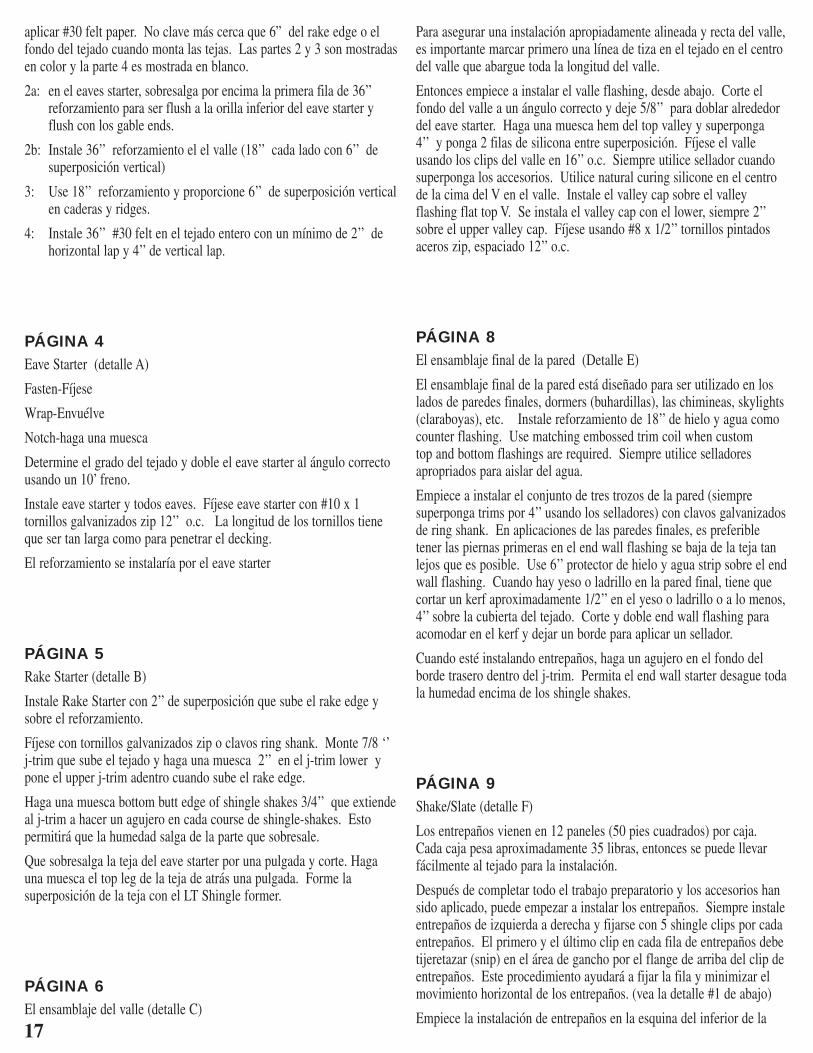
aplicar #30 felt paper . No clave más cerca que 6” del rake edge o el fondo del tejado cuando monta las tejas . Las partes 2 y 3 son mostradas en color y la parte 4 es mostrada en blanco .
2a: en el eaves starter, sobresalga por encima la primera fila de 36’’ reforzamiento para ser flush a la orilla inferior del eave starter y flush con los gable ends .
2b: Instale 36’’ reforzamiento el el valle (18’’ cada lado con 6’’ de superposición vertical)
3: Use 18’’ reforzamiento y proporcione 6’’ de superposición vertical en caderas y ridges .
4: Instale 36’’ #30 felt en el tejado entero con un mínimo de 2’’ de horizontal lap y 4’’ de vertical lap .
PÁGINA 4Eave Starter (detalle A)
Fasten-Fíjese
Wrap-Envuélve
Notch-haga una muesca
Determine el grado del tejado y doble el eave starter al ángulo correcto usando un 10’ freno .
Instale eave starter y todos eaves . Fíjese eave starter con #10 x 1 tornillos galvanizados zip 12’’ o .c . La longitud de los tornillos tiene que ser tan larga como para penetrar el decking .
El reforzamiento se instalaría por el eave starter
PÁGINA 5Rake Starter (detalle B)
Instale Rake Starter con 2’’ de superposición que sube el rake edge y sobre el reforzamiento .
Fíjese con tornillos galvanizados zip o clavos ring shank . Monte 7/8 ‘’ j-trim que sube el tejado y haga una muesca 2’’ en el j-trim lower y pone el upper j-trim adentro cuando sube el rake edge .
Haga una muesca bottom butt edge of shingle shakes 3/4’’ que extiende al j-trim a hacer un agujero en cada course de shingle-shakes . Esto permitirá que la humedad salga de la parte que sobresale .
Que sobresalga la teja del eave starter por una pulgada y corte . Haga una muesca el top leg de la teja de atrás una pulgada . Forme la superposición de la teja con el LT Shingle former .
PÁGINA 6El ensamblaje del valle (detalle C)
Para asegurar una instalación apropiadamente alineada y recta del valle, es importante marcar primero una línea de tiza en el tejado en el centro del valle que abargue toda la longitud del valle .
Entonces empiece a instalar el valle flashing, desde abajo . Corte el fondo del valle a un ángulo correcto y deje 5/8’’ para doblar alrededor del eave starter . Haga una muesca hem del top valley y superponga 4’’ y ponga 2 filas de silicona entre superposición . Fíjese el valle usando los clips del valle en 16’’ o .c . Siempre utilice sellador cuando superponga los accesorios . Utilice natural curing silicone en el centro de la cima del V en el valle . Instale el valley cap sobre el valley flashing flat top V . Se instala el valley cap con el lower, siempre 2’’ sobre el upper valley cap . Fíjese usando #8 x 1/2’’ tornillos pintados aceros zip, espaciado 12’’ o .c .
PÁGINA 8El ensamblaje final de la pared (Detalle E)
El ensamblaje final de la pared está diseñado para ser utilizado en los lados de paredes finales, dormers (buhardillas), las chimineas, skylights (claraboyas), etc . Instale reforzamiento de 18’’ de hielo y agua como counter flashing . Use matching embossed trim coil when custom top and bottom flashings are required . Siempre utilice selladores apropriados para aislar del agua .
Empiece a instalar el conjunto de tres trozos de la pared (siempre superponga trims por 4’’ usando los selladores) con clavos galvanizados de ring shank . En aplicaciones de las paredes finales, es preferible tener las piernas primeras en el end wall flashing se baja de la teja tan lejos que es posible . Use 6’’ protector de hielo y agua strip sobre el end wall flashing . Cuando hay yeso o ladrillo en la pared final, tiene que cortar un kerf aproximadamente 1/2’’ en el yeso o ladrillo o a lo menos, 4’’ sobre la cubierta del tejado . Corte y doble end wall flashing para acomodar en el kerf y dejar un borde para aplicar un sellador .
Cuando esté instalando entrepaños, haga un agujero en el fondo del borde trasero dentro del j-trim . Permita el end wall starter desague toda la humedad encima de los shingle shakes .
PÁGINA 9Shake/Slate (detalle F)
Los entrepaños vienen en 12 paneles (50 pies cuadrados) por caja . Cada caja pesa aproximadamente 35 libras, entonces se puede llevar fácilmente al tejado para la instalación .
Después de completar todo el trabajo preparatorio y los accesorios han sido aplicado, puede empezar a instalar los entrepaños . Siempre instale entrepaños de izquierda a derecha y fijarse con 5 shingle clips por cada entrepaños . El primero y el último clip en cada fila de entrepaños debe tijeretazar (snip) en el área de gancho por el flange de arriba del clip de entrepaños . Este procedimiento ayudará a fijar la fila y minimizar el movimiento horizontal de los entrepaños . (vea la detalle #1 de abajo)
Empiece la instalación de entrepaños en la esquina del inferior de la
18
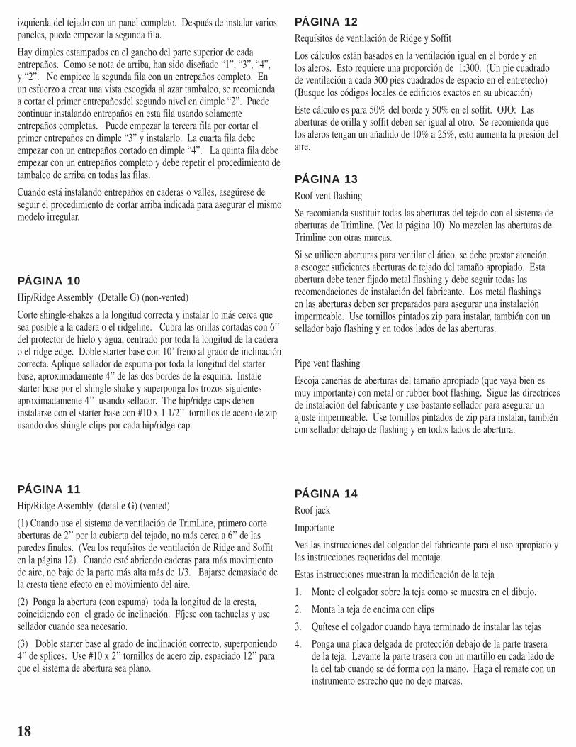
izquierda del tejado con un panel completo . Después de instalar varios paneles, puede empezar la segunda fila .
Hay dimples estampados en el gancho del parte superior de cada entrepaños . Como se nota de arriba, han sido diseñado “1”, “3”, “4”, y “2” . No empiece la segunda fila con un entrepaños completo . En un esfuerzo a crear una vista escogida al azar tambaleo, se recomienda a cortar el primer entrepañosdel segundo nivel en dimple “2” . Puede continuar instalando entrepaños en esta fila usando solamente entrepaños completas . Puede empezar la tercera fila por cortar el primer entrepaños en dimple “3” y instalarlo . La cuarta fila debe empezar con un entrepaños cortado en dimple “4” . La quinta fila debe empezar con un entrepaños completo y debe repetir el procedimiento de tambaleo de arriba en todas las filas .
Cuando está instalando entrepaños en caderas o valles, asegúrese de seguir el procedimiento de cortar arriba indicada para asegurar el mismo modelo irregular .
PÁGINA 10Hip/Ridge Assembly (Detalle G) (non-vented)
Corte shingle-shakes a la longitud correcta y instalar lo más cerca que sea posible a la cadera o el ridgeline . Cubra las orillas cortadas con 6’’ del protector de hielo y agua, centrado por toda la longitud de la cadera o el ridge edge . Doble starter base con 10’ freno al grado de inclinación correcta . Aplique sellador de espuma por toda la longitud del starter base, aproximadamente 4’’ de las dos bordes de la esquina . Instale starter base por el shingle-shake y superponga los trozos siguientes aproximadamente 4’’ usando sellador . The hip/ridge caps deben instalarse con el starter base con #10 x 1 1/2’’ tornillos de acero de zip usando dos shingle clips por cada hip/ridge cap .
PÁGINA 11Hip/Ridge Assembly (detalle G) (vented)
(1) Cuando use el sistema de ventilación de TrimLine, primero corte aberturas de 2’’ por la cubierta del tejado, no más cerca a 6’’ de las paredes finales . (Vea los requísitos de ventilación de Ridge and Soffit en la página 12) . Cuando esté abriendo caderas para más movimiento de aire, no baje de la parte más alta más de 1/3 . Bajarse demasiado de la cresta tiene efecto en el movimiento del aire .
(2) Ponga la abertura (con espuma) toda la longitud de la cresta, coincidiendo con el grado de inclinación . Fíjese con tachuelas y use sellador cuando sea necesario .
(3) Doble starter base al grado de inclinación correcto, superponiendo 4’’ de splices . Use #10 x 2’’ tornillos de acero zip, espaciado 12’’ para que el sistema de abertura sea plano .
PÁGINA 12Requísitos de ventilación de Ridge y Soffit
Los cálculos están basados en la ventilación igual en el borde y en los aleros . Esto requiere una proporción de 1:300 . (Un pie cuadrado de ventilación a cada 300 pies cuadrados de espacio en el entretecho) (Busque los códigos locales de edificios exactos en su ubicación)
Este cálculo es para 50% del borde y 50% en el soffit . OJO: Las aberturas de orilla y soffit deben ser igual al otro . Se recomienda que los aleros tengan un añadido de 10% a 25%, esto aumenta la presión del aire .
PÁGINA 13Roof vent flashing
Se recomienda sustituir todas las aberturas del tejado con el sistema de aberturas de Trimline . (Vea la página 10) No mezclen las aberturas de Trimline con otras marcas .
Si se utilicen aberturas para ventilar el ático, se debe prestar atención a escoger suficientes aberturas de tejado del tamaño apropiado . Esta abertura debe tener fijado metal flashing y debe seguir todas las recomendaciones de instalación del fabricante . Los metal flashings en las aberturas deben ser preparados para asegurar una instalación impermeable . Use tornillos pintados zip para instalar, también con un sellador bajo flashing y en todos lados de las aberturas .
Pipe vent flashing
Escoja canerias de aberturas del tamaño apropiado (que vaya bien es muy importante) con metal or rubber boot flashing . Sigue las directrices de instalación del fabricante y use bastante sellador para asegurar un ajuste impermeable . Use tornillos pintados de zip para instalar, también con sellador debajo de flashing y en todos lados de abertura .
PÁGINA 14Roof jack
Importante
Vea las instrucciones del colgador del fabricante para el uso apropiado y las instrucciones requeridas del montaje .
Estas instrucciones muestran la modificación de la teja
1 . Monte el colgador sobre la teja como se muestra en el dibujo .
2 . Monta la teja de encima con clips
3 . Quítese el colgador cuando haya terminado de instalar las tejas
4 . Ponga una placa delgada de protección debajo de la parte trasera de la teja . Levante la parte trasera con un martillo en cada lado de la del tab cuando se dé forma con la mano . Haga el remate con un instrumento estrecho que no deje marcas .

20
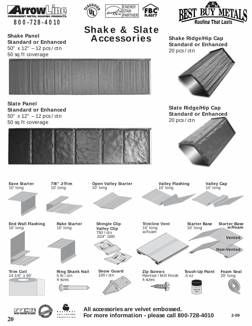
Shake & Slate Accessories
8 0 0 - 7 2 8 - 4 0 1 0
All accessories are velvet embossed.For more information - please call 800-728-4010 2-09
Eave Starter10’ long
End Wall Flashing10’ long
Shingle ClipValley Clip750 / ctn.024” G90
Trimline Vent10’ longw/foam
Starter Base10’ long
Trim Coil14 1/4” x 50’
Ring Shank Nail5 lb / ctn4 sizes
Zip ScrewsPainted / Mill Finish4 sizes
Touch-Up Paint.5 oz
Foam Seal20’ long
Rake Starter10’ long
7/8” J-Trim10’ long
Valley Flashing10’ long
Snow Guard100 / ctn
Valley Cap10’ long
Vented
Non-Vented
Starter Basew/Foam
Open Valley Starter10’ long
Slate PanelStandard or Enhanced50” x 12” – 12 pcs / ctn50 sq ft coverage
Slate Ridge/Hip CapStandard or Enhanced20 pcs / ctn
Shake PanelStandard or Enhanced50” x 12” – 12 pcs / ctn50 sq ft coverage
Shake Ridge/Hip CapStandard or Enhanced20 pcs / ctn
Roofing That Lasts
BB
M