Embed Size (px)
Citation preview

ARMY TECHNICAL MANUAL *TM 5-4930-233-14MARINE CORPS TECHNICAL MANUAL TM 4930-14/1
TECHNICAL MANUALOPERATOR, UNIT, DIRECT SUPPORT AND
GENERAL SUPPORT MAINTENANCE MANUAL
LUBRICATION AND SERVICING UNIT,POWER OPERATED,
TRAILER MOUNTED, 15 CFM COMPRESSORMODEL LST-178A-85
(NSN 4930-01-230-0781)
INTRODUCTION 1-1
OPERATING INSTRUCTIONS 2-1
OPERATOR'S MAINTENANCE 3-1INSTRUCTIONS
UNIT MAINTENANCE INSTRUCTIONS 4-1
DIRECT SUPPORT MAINTENANCE 5-1
GENERAL SUPPORT MAINTENANCE 6-1
Distribution Statement A: Approved for public release; distribution is unlimited.
*This manual supersedes TM 54930-233-14, dated 14 August 1989.
HEADQUARTERS, DEPARTMENT OF THE ARMYHEADQUARTERS, U.S. MARINE CORPS
30 JUNE 1993

TM 5-4930-233-14TM 4930-14/1
C1HEADQUARTERS,
CHANGE DEPARTMENT OF THE ARMYAND HEADQUARTERS, U.S. MARINE CORPS
NO. 1 WASHINGTON, D.C., 1 June 1995
Operator, Unit, Direct Supportand General Support Maintenance Manual
Lubrication and Servicing Unit,Power Operated,
Trailer Mounted, 15 CFM CompressorModel LST-178A-85
(NSN 4930-01-230-0781)
DISTRIBUTION STATEMENT A: Approved for public release; distribution is unlimited
TM 5-4930-233-14, 30 June 1993, is changed as follows:
1. Remove and insert pages as indicated below. New or changed text material is indicated by a vertical bar in themargin. An illustration change is indicated by a miniature pointing hand.
Remove pages Insert pagesi and ii i and ii1-1 through 1-6 1-1 through 1-62-3 and 2-4 2-3 and 2-42-11 and 2-12 2-11 and 2-122-35 and 2-36 2-35 and 2-363-9 through 3-12 3-9 through 3-124-1 and 4-2 4-1 and 4-24-17 through 4-20 4-17 through 4-20--- 4-32.1 through 4-32.44-33 through 4-36 4-33 through 4-364-51 and 4-52 4-51 and 4-52--- (4-52.1 blank)/4-52.24-53 through 4-56 4-53 through 4-564-59 and 4-60 4-59 and 4-604-105 and 4-106 4-105 and 4-1064-129 through 4-136 4-129 through 4-1364-155 and 4-156 4-155 and 4-1564-163 and 4-164 4-163 and 4-1645-1 and 5-2 5-1 and 5-2--- 5-12.1 and 5-12.25-13 and 5-14 (5-13 blank)/5-145-25 through 5-28 ---

TM 5-4930-233-14TM 4930-14/1
C1
Remove pages Insert pages5-29 and 5-30 5-29 and 5-305-51 and 5-52 5-51/(5-52 blank)5-81 through 5-84 5-81 through 5-845-91 and 5-92 5-91 and 5-925-97 and 5-98 5-97 and 5-985-105 and 5-106 5-105 and 5-1065-113 and 5-114 5-113 and 5-1146-1 through 6-4 6-1 through 6-4B-3 through B-6 B-3 through B-6C-1 through C-5/(C-6 blank) C-1 through C-5/(C-6 blank)
2. Retain this sheet in front of manual for reference purposes.
By Order of the Secretaries of the Army and Navy (Including the Marine Corps):
GORDON R. SULLIVANGeneral, United States Army
Official: Chief of Staff
JOEL B. HUDSONActing Administrative Assistant to the
Secretary of the Army
DAVID E. BOTTORFFRear Admiral, CEC, US NavyCommanderNavy Facilities EngineeringCommand
D. R. BLOOMERColonel, USMCDirector, Program SupportMarine Corps Systems Command
DISTRIBUTION:To be distributed in accordance with DA Form 12-25E. block no. 2666, requirements for TM 5-4930-233-14.
TM 5-4930-233-14TM 4930-14/1
WARNINGDo not operate the engine indoors without taking precautions to vent the exhaustgases. Engine exhaust contains carbon monoxide, a colorless, odorless, deadlypoisonous gas.
WARNING
Always wear safety glasses while operating lubrication and servicing unit. Failureto do so can lead to severe personal injury.
WARNING
Do not use compressed air for blowing dirt from your clothing or skin. Air canenter body openings and cause severe injury or death. Avoid horseplay withcompressed air.
WARNING
Trailer and towing vehicles should be on level ground to prevent accidentalmovement resulting in injury to personnel.
WARNING
Trailer wheels must be chocked even if parking brake is applied. The parkingbrake will release within 1-1/2 hours and if not correctly chocked the trailer mayroll causing severe personal injury or death.
WARNING
Do not smoke or use an open flame in the vicinity when servicing the batteries.Batteries generate hydrogen gas, which can explode causing severe injury oreven death.
WARNING
Clean all parts in a well ventilated area. Avoid inhaling solvent fumes andprolonged exposure of the skin to cleaning solvent. Failure to do so can causesevere injury or DEATH. Do not use near flame or excessive heat. Flash point ofsolvent is 100°F to 138°F (380C to 59°C).
WARNING
Serious burns can result from touching an overheated brake drum.
a

TM 5-4930-233-14TM 4930-14/1
WARNING
All nonessential personnel must be clear of vehicle area to avoid injury.
WARNING
Do not use open flame or smoke when working on the fuel system. An explosionmay occur, causing severe injury or death.
WARNING
Release pressure from hoses by activating dispensing handle and disconnectlines slowly; otherwise pressure in lines may result in injury.
WARNING
When working on electrical components remove all jewelry, dogtags, and metalitems to avoid electrical shock and burns.
WARNING
Do not remove cylinder completely with a wrench. If cylinder cannot be easilyunscrewed by hand after it has been loosened, pressure is probably trappedinside.
WARNING
Venting pressure before removal is necessary because a pressurized cylinder canfly off with damaging force that can cause personal injury.
WARNING
Protective goggles must be worn when drilling cylinder to prevent personnelinjury caused by metal shavings flying out under pressure.
WARNING
Worn or damaged parts can cause equipment malfunction which can lead toserious injury or equipment damage. Replace all damaged or worn parts.
WARNING
The adjustment procedure which follows can be dangerous for unskilledpersonnel because improper loosening of the nuts and adjustment screw couldcause the control valve connections to blow apart with resultant injury topersonnel and property, since lubricant is under high pressure.
b
TM 5-4930-233-14TM 4930-14/1
WARNING
Cleaning solvent tricholoroethane (Tri-ethane) is flammable and toxic to the skin,eyes, and respiratory tract. Skin, eye, and respiratory tract protection is required.
WARNING
Compressed air used for cleaning or drying can create airborne particles that mayenter the eyes. Pressure shall not exceed 30 psi (207 KPa). Wearing of goggles isrequired.
WARNING
Bottom plug is spring loaded. Remove with extreme care to avoid personal injury.
WARNING
Any time the trailer is jacked up, ensure jackstands are used to avoid personalinjury.
c/(d blank)

*TM 5-4930-233-14TM 4930-14/1
TECHNICAL MANUAL HEADQUARTERS,No. 5493023314 DEPARTMENT OF THE ARMY
493014/1 AND HEADQUARTERS, U.S. MARINE CORPSWashington, D.C., 30 June 1993
Operator, Unit, Direct Supportand General Support Maintenance Manual
LUBRICATION AND SERVICING UNIT,POWER OPERATED,
TRAILER MOUNTED, 15 CFM COMPRESSORMODEL LST-178A-85
(NSN 4930-01-230-0781)
REPORTING ERRORS AND RECOMMENDING IMPROVEMENTS
You can help improve this manual. If you find any mistakes or if you know of a way to improve the procedures,please let us know. Mail your letter, DA Form 2028 (Recommended Changes to Publications and Blank Forms),or DA Form 2028-2 located in the back of this manual direct to: Commander, US Army Aviation and TroopCommand, ATTN: AMSAT-I-MP, 4300 Goodfellow Blvd., St. Louis, MO 63120-1798. Marine Corps personnelsubmit NAVMC 10722 Form to Commanding General, Marine Corps Logistics Base I (Code 808-1), Albany, GA31704-5000. A reply will be furnished directly to you.
DISTRIBUTION STATEMENT A: Approved for public release; distribution is unlimited.TABLE OF CONTENTS
Paragraphs PagesCHAPTER 1. INTRODUCTIONSection I. General information .......................................................................... 1-1 1-1
II. Equipment description ...................................................................... 1-7 1-2III. Technical principles of operations ..................................................... 1-9 1-5
CHAPTER 2. OPERATING INSTRUCTIONSSection I. Description and use of operator's control
and indicators ................................................................................... 2-1 2-1II. Operator's preventive maintenance checks
and services (PMCS) ........................................................................ 2-3 2-7III. Operation under usual conditions....................................................... 2-5 2-12IV. Operation under unusual conditions................................................... 2-9 2-34
Chapter 3. OPERATOR'S MAINTENANCE INSTRUCTIONSSection I. Lubrication instructions ..................................................................... 3-1 3-1
II. Operator troubleshooting .................................................................. 3-3 3-3III. Operator maintenance procedures..................................................... 3-4 3-10
Chapter 4. UNIT MAINTENANCE INSTRUCTIONSSection I. Repair parts, special tools, TMDE and
support equipment ............................................................................ 4-1 4-1
*This manual supersedes TM 5-4930-233-14, dated 14 August 1989
i
TM 5-4930-233-14TM 4930-14/1
Paragraphs Pages
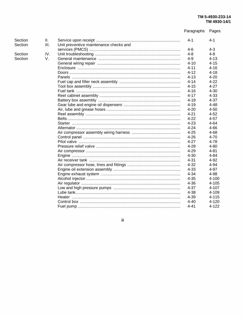
Section II. Service upon receipt ......................................................................... 4-1 4-1Section III. Unit preventive maintenance checks and
services (PMCS) ............................................................................... 4-6 4-3Section IV. Unit troubleshooting .......................................................................... 4-8 4-8Section V. General maintenance ....................................................................... 4-9 4-13
General wiring repair ........................................................................ 4-10 4-15Enclosure ......................................................................................... 4-11 4-16Doors ................................................................................................ 4-12 4-18Panels .............................................................................................. 4-13 4-20Fuel cap and filler neck assembly ..................................................... 4-14 4-22Tool box assembly ............................................................................ 4-15 4-27Fuel tank .......................................................................................... 4-16 4-30Reel cabinet assembly ...................................................................... 4-17 4-33Battery box assembly ....................................................................... 4-18 4-37Gear lube and engine oil dispensers ................................................. 4-19 4-48Air, lube and grease hoses ................................................................ 4-20 4-50Reel assembly .................................................................................. 4-21 4-52Belts .................................................................................................. 4-22 4-57Starter .............................................................................................. 4-23 4-64Alternator .......................................................................................... 4-24 4-66Air compressor assembly wiring harness .......................................... 4-25 4-68Control panel .................................................................................... 4-26 4-70Pilot valve ........................................................................................ 4-27 4-78Pressure relief valve ......................................................................... 4-28 4-80Air compressor .................................................................................. 4-29 4-81Engine .............................................................................................. 4-30 4-84Air receiver tank ............................................................................... 4-31 4-92Air compressor hose, lines and fittings .............................................. 4-32 4-94Engine oil extension assembly .......................................................... 4-33 4-97Engine exhaust system ..................................................................... 4-34 4-98Alcohol injector .................................................................................. 4-35 4-100Air regulator ...................................................................................... 4-36 4-105Low and high pressure pumps .......................................................... 4-37 4-107Lube tank........................................................................................... 4-38 4-109Heater .............................................................................................. 4-39 4-115Control box ....................................................................................... 4-40 4-120Fuel pump ......................................................................................... 4-41 4-122
ii

TM 5-4930-233-14TM 4930-14/1
Paragraphs Pages
Winterization wiring harness .............................................................. 4-42 4-124Ducts, heater hoses and exhaust system .......................................... 4-43 4-126Lube piping........................................................................................ 4-44 4-128Pneumatic piping............................................................................... 4-45 4-132Trailer components............................................................................ 4-46 4-136Coupler.............................................................................................. 4-47 4-140Emergency relay valve ...................................................................... 4-48 4-142Air supply valve ................................................................................. 4-49 4-144Air cleaner assembly ......................................................................... 4-50 4-146Brake lines and hoses........................................................................ 4-51 4-150Air tank.............................................................................................. 4-52 4-153Junction box ..................................................................................... 4-53 4-154Clearance light .................................................................................. 4-54 4-158Stop and turn light ............................................................................. 4-55 4-160Trailer wiring harness......................................................................... 4-56 4-162Wheel and tire assembly ................................................................... 4-57 4-165Brake assembly ................................................................................. 4-58 4-169Jack leg assembly ............................................................................. 4-59 4-173
Section VI. Preparation for storage and shipment ................................................ 4-60 4-175Preservation ..................................................................................... 4-60 4-175Packing, shipment and storage.......................................................... 4-61 4-177Inspection in administrative storage .................................................. 4-62 4-179
Chapter 5. DIRECT SUPPORT MAINTENANCE INSTRUCTIONS
Section I. Direct support troubleshooting ........................................................... 5-1 5-1Section II. Maintenance procedures.................................................................... 5-2 5-9
Enclosure and skid assembly............................................................. 5-2 5-9Doors................................................................................................. 5-3 5-11Panel................................................................................................. 5-4 5-13Transfer pump ................................................................................... 5-5 5-14Fuel tank assembly............................................................................ 5-6 5-25Gear lube dispenser........................................................................... 5-7 5-29Engine oil dispenser .......................................................................... 5-8 5-37Grease control valve ......................................................................... 5-9 5-45Air, lube and grease hoses................................................................. 5-10 5-51Air compressor assembly test ........................................................... 5-11 5-52Starter ............................................................................................... 5-12 5-53Alternator........................................................................................... 5-13 5-58Air compressor .................................................................................. 5-14 5-66
iii

TM 5-4930-233-14TM 4930-14/1
Paragraphs Pages
Air compressor head.......................................................................... 5-15 5-78Centrifugal unloader ......................................................................... 5-16 5-85Air regulator ...................................................................................... 5-17 5-87Low pressure pump .......................................................................... 5-18 5-89High pressure pump .......................................................................... 5-19 5-102Lube tank .......................................................................................... 5-20 5-119Winterization control box .................................................................. 5-21 5-121A frame and skid assembly ............................................................... 5-22 5-123Power cluster .................................................................................... 5-23 5-125Axle assembly .................................................................................. 5-24 5-130Frame assembly ............................................................................... 5-25 5-132
Chapter 6. GENERAL SUPPORT MAINTENANCE INSTRUCTIONSFuel tank .......................................................................................... 6-1 6-1A frame and skid assembly ............................................................... 6-2 6-3Frame assembly ............................................................................... 6-3 6-5
Appendix A. REFERENCES ................................................................................. A-1 A-1Appendix B. MAINTENANCE ALLOCATION CHART .......................................... B-1 B-1Section I. Introduction
General ............................................................................................ B-1 B-1Maintenance functions ...................................................................... B-2 B-1Explanation of columns in the MAC .................................................. B-3 B-2Explanation of columns in tool and testequipment requirements .................................................................... B-4 B-3Explanation of columns in remarks ................................................... B-5 B-3
Section II. Maintenance Allocation Chart ........................................................... B-4Section III. Tools and test requirements .............................................................. B-7Section IV. Remarks ........................................................................................... B-8Appendix C. COMPONENTS OF END ITEM AND BASIC ISSUE ITEMS LISTSection I. Scope ............................................................................................... C-1 C-1
General ............................................................................................ C-2 C-1Explanation of columns .................................................................... C-3 C-1
Section II. Components of end item ................................................................... C-2Section III. Basic Issue Items .............................................................................. C-5Appendix D. ADDITIONAL AUTHORIZATION LIST
NOT APPLICABLE
iv
TM 5-4930-233-14TM 4930-14/1
Paragraphs Pages
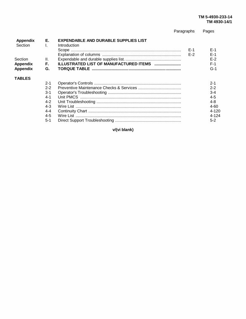
Appendix E. EXPENDABLE AND DURABLE SUPPLIES LISTSection I. Introduction
Scope ............................................................................................... E-1 E-1Explanation of columns .................................................................... E-2 E-1
Section II. Expendable and durable supplies list. ................................................ E-2Appendix F. ILLUSTRATED LIST OF MANUFACTURED ITEMS ....................... F-1Appendix G. TORQUE TABLE ................................ ................................ ............. G-1
TABLES2-1 Operator's Controls ........................................................................... 2-12-2 Preventive Maintenance Checks & Services ..................................... 2-23-1 Operator's Troubleshooting ............................................................... 3-44-1 Unit PMCS ....................................................................................... 4-54-2 Unit Troubleshooting ......................................................................... 4-84-3 Wire List ........................................................................................... 4-604-4 Continuity Chart ................................................................................ 4-1204-5 Wire List ........................................................................................... 4-1245-1 Direct Support Troubleshooting ......................................................... 5-2
v/(vi blank)

TM 5-4930-233-14TM 4930-14/1
Chapter 1
INTRODUCTION
Section I. GENERAL INFORMATION1-1. SCOPE
Type of Manual: Operator, Unit, Direct Support and General Support Maintenance Manual.
Model Number and Equipment Name: Lubrication and Servicing Unit, Power Operated, Trailer Mounted (LST-178A-85).
Purpose of Equipment: To lubricate all types of equipment at remote locations.
1-2. MAINTENANCE FORMS AND RECORDS
Department of the Army forms and procedures used for equipment maintenance will be those prescribed by DA PAM 738-750, The Army Maintenance Management System (TAMMS). Marine Corps forms and procedures used for equipment maintenance will be those prescribed by TM 4700-15/1 E.
1-3. DESTRUCTION OF ARMY MATERIAL TO PREVENT ENEMY USE
Refer to TM 750-244-3, Procedures for Destruction of Equipment to Prevent Enemy Use, for information about destruction.
1-4. PREPARATION FOR STORAGE OR SHIPMENT
Instructions for preparation for storage or shipment are contained in Chapter 4, Section VI.
1-5. REPORTING EQUIPMENT IMPROVEMENT RECOMMENDATIONS (EIRs)
If your lubrication and servicing unit needs improvement let us know. Send us an EIR. You, the user, are the only one who can tell us why a procedure is hard to perform. Put it on an SF 368 (Quality Deficiency Report). Mail it directly to Commander, U.S. Army Aviation and Troop Command, ATTN: AMSAT-I-MDO, 4300 Goodfellow Boulevard, St. Louis, MO 63120-1798. Marine Corps users mail it directly to Commanding General, MCLB (Code 808-1), Albany, Georgia 31705. A reply will be furnished directly to you.
1-6. WARRANTY INFORMATION
The Lubrication and Servicing Unit, Power Operated, Trailer Mounted (LST-178A-85) is warranted for two years from the date first placed into use by the Government, not to exceed beyond five years from date of initial delivery.The warranty starts on the date found in block 23, DA Form 2408-9 in the logbook. Report all defects in material and workmanship to your supervisor who will take appropriate action.
1-1

TM 10-4930-233-14TM 4930-14/1
Section II. EQUIPMENT DESCRIPTION
1-7. EQUIPMENT CHARACTERISTICS, CAPABILITIES, AND FEATURES
The lubrication and servicing unit provides a highly mobile servicing station for all types of self-propelled andstationary equipment.
a. Self contained, mobile gasoline powered unit
b. Can be towed by vehicles operating with 12 or 24 Vdc electrical systems
c. Contains three lubricant storage tanks (grease, engine oil, and gear oil)
d. Has four lubricant dispensers mounted on reels (two for grease, one each for engine oil and gear oil)
e. Has air chuck mounted on a reel for air servicing
f. Carries a transfer pump for pressurized dispensing from 55 gallon drums
g. Has a set of hand guns, adapters, couplings, etc. on board for specialized lube jobs
1-8 LOCATION AND DESCRIPTION OF MAJOR COMPONENTS
a. Enclosure (1). Gives protection to the skid subassembly parts from extremes in weather.
b. Gear Lube Dispenser(2). Dispenses pressurized gear lubrication.
c. Grease Control Valves (3). Dispense pressurized grease.
d. Air Service (4). Used to service air fills parts (such as tires) or operate auxiliary equipment (such as transferpump).
e. Engine Oil Dispenser (5). Dispenses pressurized engine oil.
f. Air Compressor Assembly (6). Generates and stores compressed air for use in dispensing lubricants.
g. Control Panel (7). Contains operator control switches and gages.
h. Lube Tank And Dispenser Pumps (8). Stores and pumps lubricants from lube tank compartments to dispensers.
i. Transfer Pump (9). Used to pump lubricants from storage drums.
j. Tool and Accessory Storage (10). Storage provided for tools and specialized lubricating equipment
k. Winterization Assembly (11). Used to aid operation of equipment in cold weather by providing heated air tovarious parts.
l. Skid Assembly (12). A removable base for attachment of lube and service parts.
m. Trailer Assembly (13). A mobile platform for mounting the skid assembly. Provides brakes and lights for safety.
n. Data Plates (14). These data plates contain trailer and manufacturer's identification.
Change 1 1-2

TM 10-4930-233-14TM 4930-14/1
o. Batteries (15). Engine draws power from batteries in order to crank engine.
p. Battery Box (16). Storage for batteries.
q. Gas Tank (17).
Change 1 1-3

TM 10-4930-233-14TM 4930-14/1
1-9. EQUIPMENT DATA
Manufacturer ...................................................................................McGraw Commercial Equipment Co.NSN ................................................................................................................................4930012300781Type ..................................................................................................................Compressed air operatedCompressor drive ............................................................................................................Gasoline engineLubricants dispensed ............................................................................... Grease, engine oil, and gear oilNumber of hose reels .............................................................................................................................5Hose reel application ...............................................................................................................................2
Grease .............................................................................................................................................2Engine oil .........................................................................................................................................1Gear oil ............................................................................................................................................1Compressed air ................................................................................................................................1
Type of mounting ............................................................................................................................TrailerBrake Type ....................................................................................................................Air over hydraulicEngine ........................................................................ Military Standard Engine refer to TM 5280520314Air compressor
Manufacturer .......................................................................................................... Comp Air KelloggModel ................................................................................................................................... 335 TVXType ...................................................................................................................Reciprocating PistonDrive .......................................................................................................................................... BELTDisplacement ..................................................................................... 15 cfm (Cubic feet per minute)Stroke ...................................................................................................................................... 3 inchOperating pressure ..................................................................................................................175 psi
Transfer pumpManufacturer .......................................................................................................................ALEMITEModel No .................................................................................................................................. 72164Operating Pressure ......................................................................................................100 to 175 psi
Alcohol InjectorManufacturer .....................................................................................................................NORGRENModel ............................................................................................................................................LIZ
Lubricant PumpsManufacture ........................................................................................................................ALEMITEHigh pressure pump model .....................................................................................................7785B5High pressure pump ratio ........................................................................................................ 40 to 1Low pressure pump model ........................................................................................................7793BLow pressure pump ratio ......................................................................................................... 12 to 1
Types of lubricants requiredHigh pressure pump ........................................................................ GENERAL PURPOSE GREASELow pressure pump ..............................................................................................Engine and gear oil
Electrical System SkidType ............................................................................................................24 volts, negative groundNumber of batteries ..........................................................................................................................2
CapacitiesFuel tank ..............................................................................................................................10 gallonHydraulic brakes system ..................................................................................................... 5/16 quartAlcohol Injector ....................................................................................................................... 1/2 pintLubricant storage bins
Lubricating grease ............................................................................................................175 lbs.Lubricating gear oil .........................................................................................................27 gallonLubricating oil .................................................................................................................27 gallon
Dimension and weightOverall height ....................................................................................................................... 763/4 in.Overall length .......................................................................................................................... 184 in.
1-4
TM 10-4930-233-14TM 4930-14/1
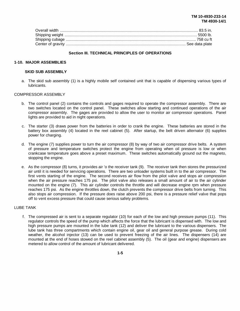
Overall width .......................................................................................................................... 83.5 in.Shipping weight ..................................................................................................................... 5500 lb.Shipping cubage ................................................................................................................... 758 cu ftCenter of gravity .......................................................................................................... See data plate
Section III. TECHNICAL PRINCIPLES OF OPERATIONS
1-10. MAJOR ASSEMBLIES
SKID SUB ASSEMBLY
a. The skid sub assembly (1) is a highly mobile self contained unit that is capable of dispensing various types oflubricants.
COMPRESSOR ASSEMBLY
b. The control panel (2) contains the controls and gages required to operate the compressor assembly. There aretwo switches located on the control panel. These switches allow starting and continued operations of the aircompressor assembly. The gages are provided to allow the user to monitor air compressor operations. Panellights are provided to aid in night operations.
c. The starter (3) draws power from the batteries in order to crank the engine. These batteries are stored in thebattery box assembly (4) located in the reel cabinet (5). After startup, the belt driven alternator (6) suppliespower for charging.
d. The engine (7) supplies power to turn the air compressor (8) by way of two air compressor drive belts. A systemof pressure and temperature switches protect the engine from operating when oil pressure is low or whencrankcase temperature goes above a preset maximum. These switches automatically ground out the magneto,stopping the engine.
e. As the compressor (8) turns, it provides air 'o the receiver tank (9). The receiver tank then stores the pressurizedair until it is needed for servicing operations. There are two unloader systems built in to the air compressor. Thefirst vents starting of the engine. The second receives air flow from the pilot valve and stops air compressionwhen the air pressure reaches 175 psi. The pilot valve also releases a small amount of air to the air cylindermounted on the engine (7). This air cylinder controls the throttle and will decrease engine rpm when pressurereaches 175 psi. As the engine throttles down, the clutch prevents the compressor drive belts from turning. Thisalso stops air compression. If the pressure does raise above 200 psi, there is a pressure relief valve that popsoff to vent excess pressure that could cause serious safety problems.
LUBE TANK
f. The compressed air is sent to a separate regulator (10) for each of the low and high pressure pumps (11). Thisregulator controls the speed of the pump which affects the force that the lubricant is dispensed with. The low andhigh pressure pumps are mounted in the lube tank (12) and deliver the lubricant to the various dispensers. Thelube tank has three compartments which contain engine oil, gear oil and general purpose grease. During coldweather, the alcohol injector (13) can be used to prevent freezing of the air lines. The dispensers (14) aremounted at the end of hoses stowed on the reel cabinet assembly (5). The oil (gear and engine) dispensers aremetered to allow control of the amount of lubricant delivered.
1-5

TM 10-4930-233-14TM 4930-14/1
Change 1 1-6
TM 5-4930-233-14TM 4930-14/1
g. Also provided is an air service chuck (15). This chuck can be used to operate some of the auxiliary equipmentsuch as the transfer pump (16). This pump is for direct dispensing of lubricant from bulk storage containers,such as 55 gallon drums.
h. The reel cabinet assembly (5) also provides storage for certain tools and equipment.
WINTERIZATION ASSEMBLY
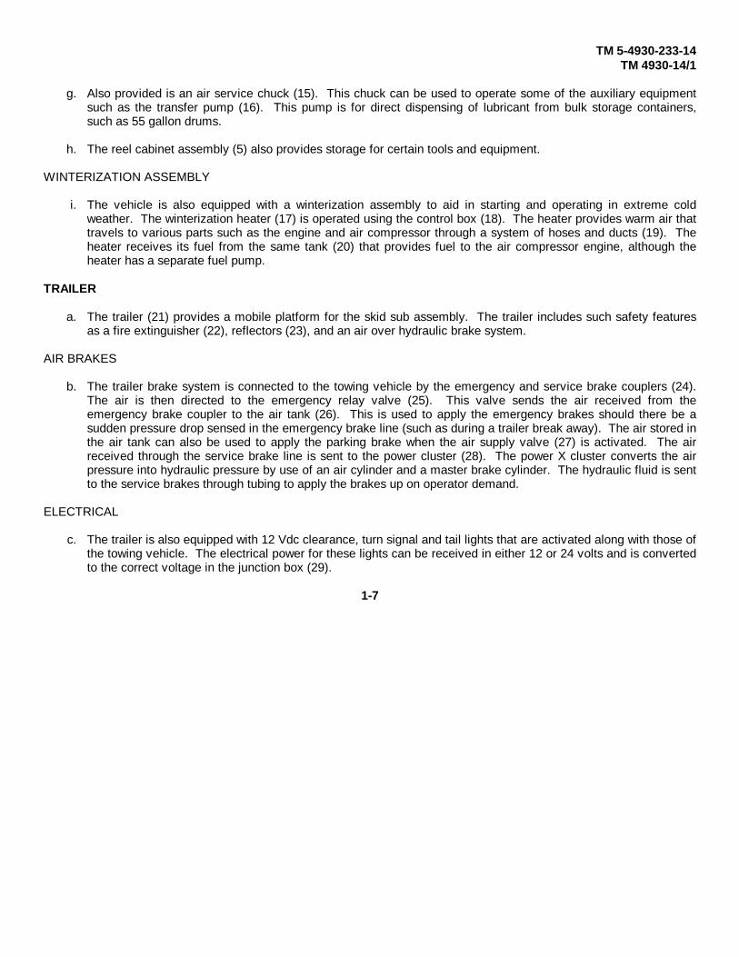
i. The vehicle is also equipped with a winterization assembly to aid in starting and operating in extreme coldweather. The winterization heater (17) is operated using the control box (18). The heater provides warm air thattravels to various parts such as the engine and air compressor through a system of hoses and ducts (19). Theheater receives its fuel from the same tank (20) that provides fuel to the air compressor engine, although theheater has a separate fuel pump.
TRAILER
a. The trailer (21) provides a mobile platform for the skid sub assembly. The trailer includes such safety featuresas a fire extinguisher (22), reflectors (23), and an air over hydraulic brake system.
AIR BRAKES
b. The trailer brake system is connected to the towing vehicle by the emergency and service brake couplers (24).The air is then directed to the emergency relay valve (25). This valve sends the air received from theemergency brake coupler to the air tank (26). This is used to apply the emergency brakes should there be asudden pressure drop sensed in the emergency brake line (such as during a trailer break away). The air stored inthe air tank can also be used to apply the parking brake when the air supply valve (27) is activated. The airreceived through the service brake line is sent to the power cluster (28). The power X cluster converts the airpressure into hydraulic pressure by use of an air cylinder and a master brake cylinder. The hydraulic fluid is sentto the service brakes through tubing to apply the brakes up on operator demand.
ELECTRICAL
c. The trailer is also equipped with 12 Vdc clearance, turn signal and tail lights that are activated along with those ofthe towing vehicle. The electrical power for these lights can be received in either 12 or 24 volts and is convertedto the correct voltage in the junction box (29).
1-7

TM 5-4930-233-14TM 4930-14/1
1-8

TM 5-4930-233-14TM 4930-14/1
Chapter 2
OPERATING INSTRUCTIONS
Section I. DESCRIPTION AND USE OF OPERATOR'S CONTROL INDICATORS
2-1. GENERAL
The lubrication and servicing unit operator's controls and indicators provide the means to ensure safe and trouble-free operation in all conditions. Constant monitoring of the instruments is required to stop problems before they start.
2-2. OPERATOR'S CONTROLSTable 2-1. OPERATOR'S CONTROLS
CONTROL ORKEY INDICATOR FUNCTION
1 PANEL LIGHTS Light controls and indicators for night operators.
2 IGNITION/START SWITCH Allows engine to run or stops it by grounding themagneto and cranks engine to start.
3 COLD START SWITCH Allows oil pressure to increase aiding coldweather engine starts.
4 THROTTLE CONTROL Control maximum engine operating speed.Locks speed setting by turning clockwise.
5 CHOKE CONTROL Pulls out to aid cold engine starting. Pushes inwhen engine is warm to maintain smoothoperation.
6 AIR PRESSURE GAGE Indicates air receiver tank pressure.
7 OIL PRESSURE GAGE Indicates engine oil pressure.
8 AMMETER Indicates the rate of charge or discharge of thebatteries in amps.
9 FUEL LEVEL GAGE Indicates level of fuel in tank.
2-1

TM 5-4930-233-14TM 4930-14/1
Table 2-1. OPERATOR'S CONTROLS - CONTINUED
CONTROL ORKEY INDICATOR FUNCTION
10 ALCOHOL INJECTOR Controls flow of alcohol into air system to preventADJUSTING SCREW freezing during cold weather.
11 ALCOHOL INJECTORSIGHT GAGE Shows level of alcohol in reservoir.
12 AIR REGULATOR Adjusts air pressure sent to the lube pumps.One regulator is supplied for each pump.
13 AIR PRESSURE GAGE Shows air pressure at lube pump to permit airregulator adjustment.
14 FLOW BACK VALVE Sends lubricants from pumps back to the lubetank and vent line pressure. One valve issupplied for each pump.
2-2

TM 10-4930-233-14TM 4930-14/1
Table 2-1. OPERATOR'S CONTROLS - CONTINUED
CONTROL ORKEY INDICATOR FUNCTION
15 DRAW VALVE LEVER Activates valve to drainmoisture and airpressure from air receiver tank
16 AIR SERVICE HOSE Connection point for air tools, chucksand auxiliary equipment.
17 GEAR OIL DISPENSER Allows controlled dispensing of gear oil.Measures to the pint.
18 ENGINE OIL DISPENSER Allows controlled dispensing of engineoil. Measures to the quart.
19 GREASE CONTROL VALVE Dispenses general purpose grease.
20 HOSE REEL LOCKS Locks hose reel to prevent excessivehose from unwinding.
2-3
TM 10-4930-233-14TM 4930-14/1
Table 2-1. OPERATOR'S CONTROLS - CONTINUED
CONTROL ORKEY INDICATOR FUNCTION
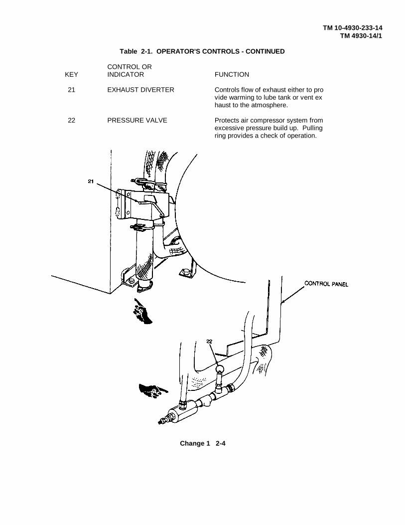
21 EXHAUST DIVERTER Controls flow of exhaust either to provide warming to lube tank or vent exhaust to the atmosphere.
22 PRESSURE VALVE Protects air compressor system fromexcessive pressure build up. Pullingring provides a check of operation.
Change 1 2-4

TM 5-4930-233-14TM 4930-14/1
Table 2-1. OPERATOR'S CONTROLS - CONTINUED
CONTROL ORKEY INDICATOR FUNCTION
23 WINTERIZATIONSTART SWITCH Starts winterization heater.
24 HEAT LEVEL SWITCH Controls winterization heater.
2-5
TM 5-4930-233-14TM 4930-14/1
Table 2-1. OPERATOR'S CONTROLS - CONTINUED
CONTROL ORKEY INDICATOR FUNCTION
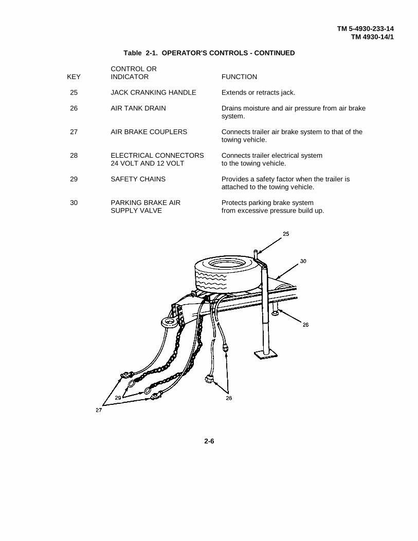
25 JACK CRANKING HANDLE Extends or retracts jack.
26 AIR TANK DRAIN Drains moisture and air pressure from air brakesystem.
27 AIR BRAKE COUPLERS Connects trailer air brake system to that of thetowing vehicle.
28 ELECTRICAL CONNECTORS Connects trailer electrical system24 VOLT AND 12 VOLT to the towing vehicle.
29 SAFETY CHAINS Provides a safety factor when the trailer isattached to the towing vehicle.
30 PARKING BRAKE AIR Protects parking brake systemSUPPLY VALVE from excessive pressure build up.
2-6
TM 5-4930-233-14TM 4930-14/1
Section II. OPERATOR'S PREVENTIVE MAINTENANCE CHECKS AND SERVICES (PMCS)
2-3. GENERAL
a. Before you operate. Always keep in mind the CAUTIONS and WARNINGS. Perform your before PMCS.
b. While you operate. Always keep in mind the CAUTIONS and WARNINGS. Perform your during PMCS.
c. On a weekly basis. Be sure to perform your weekly PMCS.
d. If your equipment fails to operate. Troubleshoot with proper equipment. Report any deficiencies using theproper forms. See DA PAM 738-750. Marine Corps users see TM 4700-15/1 E.
2-4. OPERATOR PMCS TABLE (Table 2-2.)
a. Always do your PREVENTIVE MAINTENANCE in the same order so that it gets to be a habit. Once you've hadsome practice, you'll spot anything wrong in a hurry.
b. If anything looks wrong and you can't fix it, write it on your DA Form 2404. If you find something seriously wrong,report it to unit maintenance RIGHT NOW.
c. When you do your PREVENTIVE MAINTENANCE, take along the tools you need to make all the checks. Youalways need a rag or two.
d. Bolts, nuts and screws: Check them all for obvious looseness, missing, bent or broken condition. You can't trythem all with a tool, of course, but look for chipped paint, bare metal, or rust around bolt heads. If you find oneyou think is loose, tighten it, or report it to unit maintenance if you can't tighten it.
e. Welds: Look for loose or chipped paint, rust, or gaps where parts are welded together. If you find a bad weld,report it to unit maintenance.
f. Electric wires and connectors: Look for cracked or broken insulation, bare wires, and loose or broken connectors.Tighten loose connectors and make sure the wires are in good shape.
g. Hoses and fluid lines: Look for wear, damage, and leaks, and make sure clamps and fittings are tight. Wet spotsshow leaks, of course. But a stain around a fitting or connector can mean a leak. If a leak comes from a loosefitting or connector, tighten it. If something is broken or worn out, report it to unit maintenance.
2-7
TM 5-4930-233-14TM 4930-14/1
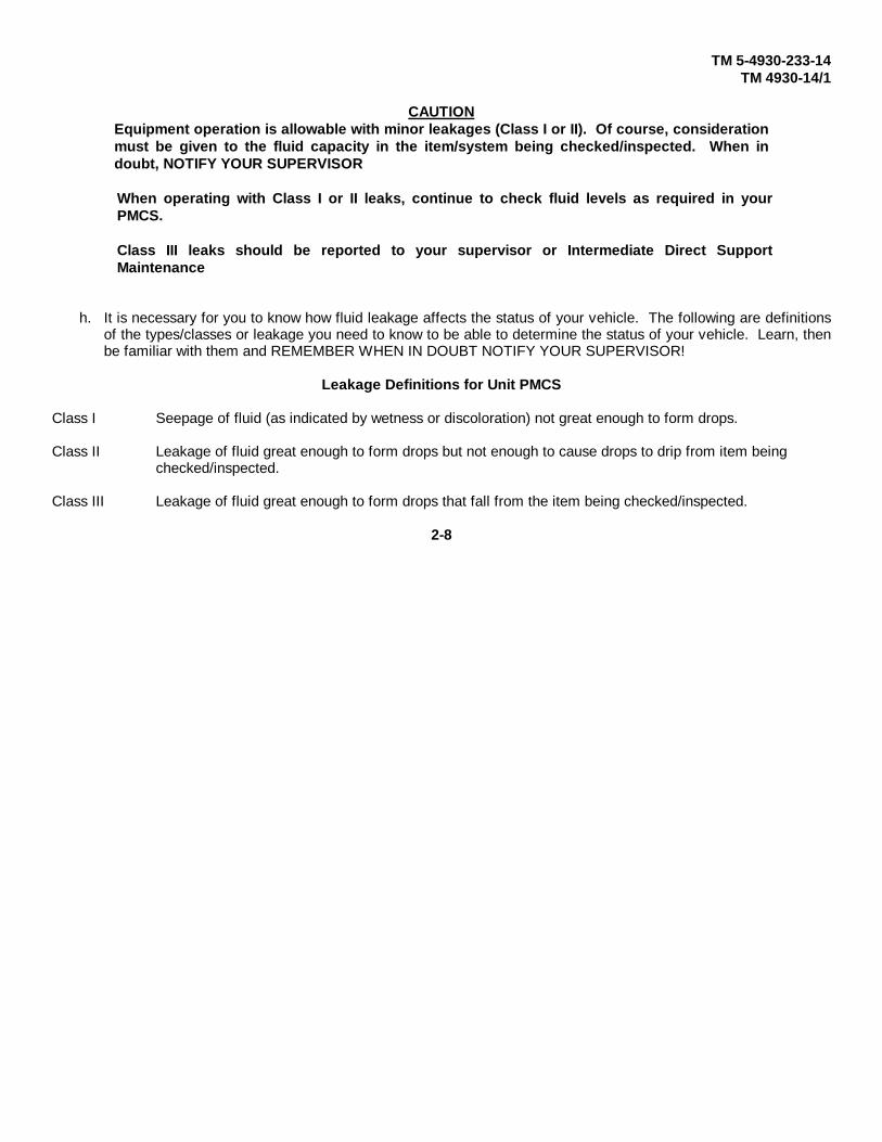
CAUTIONEquipment operation is allowable with minor leakages (Class I or II). Of course, considerationmust be given to the fluid capacity in the item/system being checked/inspected. When indoubt, NOTIFY YOUR SUPERVISOR
When operating with Class I or II leaks, continue to check fluid levels as required in yourPMCS.
Class III leaks should be reported to your supervisor or Intermediate Direct SupportMaintenance
h. It is necessary for you to know how fluid leakage affects the status of your vehicle. The following are definitionsof the types/classes or leakage you need to know to be able to determine the status of your vehicle. Learn, thenbe familiar with them and REMEMBER WHEN IN DOUBT NOTIFY YOUR SUPERVISOR!
Leakage Definitions for Unit PMCS
Class I Seepage of fluid (as indicated by wetness or discoloration) not great enough to form drops.
Class II Leakage of fluid great enough to form drops but not enough to cause drops to drip from item being checked/inspected.
Class III Leakage of fluid great enough to form drops that fall from the item being checked/inspected.
2-8

TM 5-4930-233-14TM 4930-14/1
Table 2-2. Preventive Maintenance Checks and Services
Not FullyItem Item To Check/ Mission CapableNo Interval Service Procedures If:
1. Before Fuel Tank Inspect fuel tank and fuel lines for The fuel system is leaking or
leaks or damage. damaged.
2. Before Reel Cabinet Assembly
WARNING
Do not smoke or use anopen flame in the vicinitywhen servicing the batteries.Batteries generate hydrogengas, which can explodecausing severe injury orDEATH.
Inspect batteries and battery cables The batteries or battery
for damage or loose connections. cables are missing or dam
aged.-
3. Before Air Compressor Assembly a. Inspect air compressor and alternator The drive belts are loose,
drive belts for looseness, wear or damage. worn, damaged or missing.
b. Inspect air compressor head assembly The head assembly is dam-
for damage or leaks. aged or leaking.
c. Inspect exhaust diverter and hoses
for damage or leaks.
d. Perform engine PMCS as required -
by TM 9-2805-262-14.
4. Before Lube Tank Assembly a. Check alcohol injector for alcohol
level (para 3-5) if operation
is to take place in cold weather.
b. Inspect lube tank for proper lubricant
levels. Fill as required (para 2-5).
c. Inspect lube tank compartments The lubricant is contaminated
for contamination. by water, dirt etc.
5. Before Winterization Assembly Inspect fuel line, fuel pump and heater for Fuel is leaking.
leaks or damage.
6. Before Lube and Pneumatic Inspect lube and pnuematic piping The lube and pnuematic pipingPiping for leaks, kinks, or damage. is missing, damaged or
leaking.
7. Before Air Brake Assembly a. Inspect air brake couplers, emergency The air brake components
relay valve, air cleaners, are leaking, damaged or
power cluster, air supply valve, missing.
air tank, brake lines, tubes and
fittings for leaks or damage.
2-9

TM 5-4930-233-14TM 4930-14/1
Table 2-2. Preventive Maintenance Checks and Services - (Continued)
Not FullyItem Item To Check/ Mission CapableNo Interval Service Procedures If:
b. Drain air tank of all moisture by
opening valve. Drain two air
cleaners by removing bottom
plug. Close valve and install
plug.
8. Before Trailer, Electrical Inspect trailer lights for correct operation. The tail, turn or stop lights do
not operate correctly.
9. Before Trailer Assembly Inspect frame assembly for cracked The frame assembly has
or damaged welds, corrosion or cracked or damaged weld-
warped and bent frame members. ments.
10. Before Axle Assembly Check trailer tire pressure. Service if
required (para 3-6).
11. During Transfer Pump Inspect transfer pump for proper operation,
leaks or damage.
12. During Reel Cabinet Assembly Inspect oil and grease dispensers, The dispensers or components
air, lube and grease hoses and reel are leaking, damaged
assemblies for correct operation, or missing.
damage or leaking.
13. During Air Compressor a. Observe operation of air compressor
Assembly assembly.
(1) The pilot valve should automatically
throttle the engine up and down to keep
air receiver tank pressure at 140-175 psi.
(2) Oil pressure should not drop
to below 15 psi.
(3) When engine is at idle, the The air compressor assembly
clutch should disengage the does not operate correctly.
compressor drive belts.
They should not turn.
b. Observe the operation of the The starter does not crank
starter. the engine.
c. Inspect control panel gages for Gages are illegible or not
correct operation. working.
d. Test operation of pressure relief The pressure relief valve
valve by pulling up on ring when does not "pop off".
pressure in air receiver tank is
between 140 - 175 psi.
2-10
TM 10-4930-233-14TM 4930-14/1
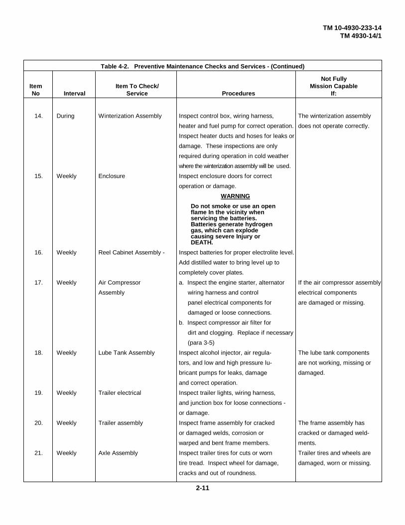
Table 4-2. Preventive Maintenance Checks and Services - (Continued)
Not FullyItem Item To Check/ Mission CapableNo Interval Service Procedures If:
14. During Winterization Assembly Inspect control box, wiring harness, The winterization assembly
heater and fuel pump for correct operation. does not operate correctly.
Inspect heater ducts and hoses for leaks or
damage. These inspections are only
required during operation in cold weather
where the winterization assembly will be used.
15. Weekly Enclosure Inspect enclosure doors for correct
operation or damage.
WARNING
Do not smoke or use an openflame In the vicinity whenservicing the batteries.Batteries generate hydrogengas, which can explodecausing severe Injury orDEATH.
16. Weekly Reel Cabinet Assembly - Inspect batteries for proper electrolite level.
Add distilled water to bring level up to
completely cover plates.
17. Weekly Air Compressor a. Inspect the engine starter, alternator If the air compressor assembly
Assembly wiring harness and control electrical components
panel electrical components for are damaged or missing.
damaged or loose connections.
b. Inspect compressor air filter for
dirt and clogging. Replace if necessary
(para 3-5)
18. Weekly Lube Tank Assembly Inspect alcohol injector, air regula- The lube tank components
tors, and low and high pressure lu- are not working, missing or
bricant pumps for leaks, damage damaged.
and correct operation.
19. Weekly Trailer electrical Inspect trailer lights, wiring harness,
and junction box for loose connections -
or damage.
20. Weekly Trailer assembly Inspect frame assembly for cracked The frame assembly has
or damaged welds, corrosion or cracked or damaged weld-
warped and bent frame members. ments.
21. Weekly Axle Assembly Inspect trailer tires for cuts or worn Trailer tires and wheels are
tire tread. Inspect wheel for damage, damaged, worn or missing.
cracks and out of roundness.
2-11
TM 10-4930-233-14TM 4930-14/1
Section III. OPERATION UNDER USUAL CONDITIONS
2-5. OPERATION PROCEDURE
NOTEBefore operating lubrication and servicing unit, be sure that Before preventive maintenancechecks and services are performed.
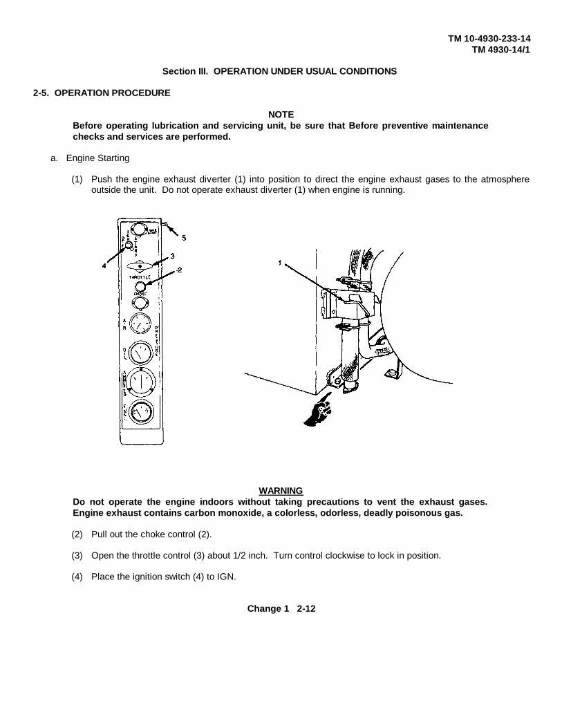
a. Engine Starting
(1) Push the engine exhaust diverter (1) into position to direct the engine exhaust gases to the atmosphereoutside the unit. Do not operate exhaust diverter (1) when engine is running.
WARNINGDo not operate the engine indoors without taking precautions to vent the exhaust gases.Engine exhaust contains carbon monoxide, a colorless, odorless, deadly poisonous gas.
(2) Pull out the choke control (2).
(3) Open the throttle control (3) about 1/2 inch. Turn control clockwise to lock in position.
(4) Place the ignition switch (4) to IGN.
Change 1 2-12

TM 5-4930-233-14TM 4930-14/1
CAUTION
When cranking the engine, you must take care to prevent startingmotor overheating. Limit your cranking intervals to 30 secondsand wait 2 minutes between attempts if the engine does not startthe first time. If the engine does not start after you have cranked itfour or five times, refer problem to unit maintenance.
5. Turn ignition switch (4) to start.
NOTE
For cold weather conditions hold cold start switch (5) on until oilpressure builds to 30 psi.
6. When engine starts, release ignition switch (4).
7. Throttle control (3) should be pulled all the way out for normal operation after engine reaches operatingtemperature.
NOTE
Engine rpm under load should be 3200 rpm. See TM 5-2806-208-14for engine rpm adjusting instructions.
8. As the engine warms up, push in the choke control (2) in increments to maintain smooth engine operationwith minimum choke setting. You should have the choke control (2) pushed in fully before the enginereaches operating temperature.
b. Engine Stopping
1. If the engine has been running under heavy compressor load and is hot, push in the throttle control (3) to runthe engine at idle until it cools (2 minutes). When the engine has cooled enough to dissipate the heat causedby the heavy load, push in the throttle control (3) fully.
2. Move the ignition switch (4) to OFF to stop engine.
3. Drain moisture that has condensed in the air receiver tank by turning lever (6) to open drain valve. Aftermoisture is drained, close drain valve.
2-13

TM 5-4930-233-14TM 4930-14/1
c. Filling Lube Tank
1. Start engine (paragraph 2-5 a)
2. Make sure the air receiver drain valve is closed by turning lever (6).
3. Air pressure in the tank will automatically build up to 175 psi. This pressure is preset to cut out at 175 psiand cut in at 140 psi.
4. Allow pressure to build until the air pressure gage shows a reading of between 140 and 175 psi air pressure.
5. Remove the transfer pump (7) and bung adapter (8) from its mounting and install in drum of lubricant to bedispensed. You cannot use the transfer pump (7) to pump heavy grease. Grease must be hand-packed inthe dispenser tank.
6. Remove the transfer pump hose assembly (9) from the tool box assembly and install on the transfer pumpassembly.
7. Pull out the air service hose (10) from the center reel assembly and attach it to the transfer pump (7).
8. Open the manhole of the lube tank compartment to be filled and insert the transfer hose.
9. Open the air valve (11) to the required volume.
10. When lube tank is filled, close air valve (11).
2-14

TM 5-4930-233-14TM 4930-14/1
NOTE
Always keep lubricant containers three-quarters full.
11. Disconnect air service hose (10) and return to stowage position.
12. Remove transfer pump (7) and bung adapter (8) from lubricant drum.
13. Clean and store the transfer pump (7) and hose (9) in their respective positions.
14. Shut down engine (paragraph 2-5 b).
15. Open the air receiver drain valve by turning lever (6) to drain moisture and air pressure from the air receivertank.
2-15
TM 5-4930-233-14TM 4930-14/1
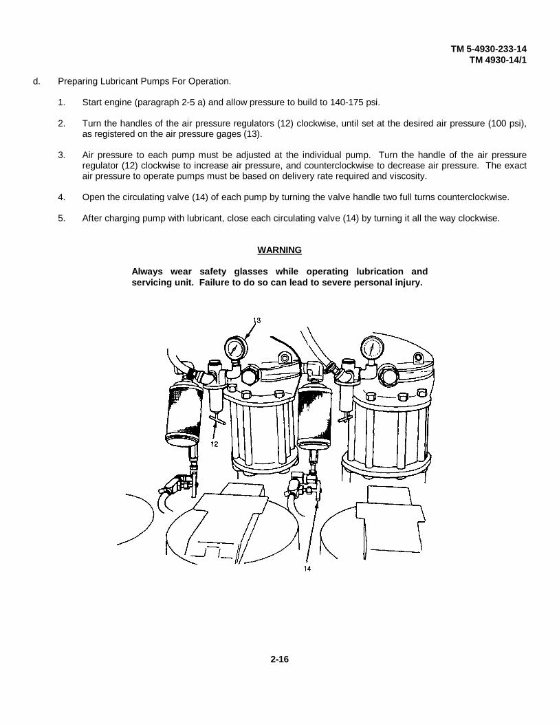
d. Preparing Lubricant Pumps For Operation.
1. Start engine (paragraph 2-5 a) and allow pressure to build to 140-175 psi.
2. Turn the handles of the air pressure regulators (12) clockwise, until set at the desired air pressure (100 psi),as registered on the air pressure gages (13).
3. Air pressure to each pump must be adjusted at the individual pump. Turn the handle of the air pressureregulator (12) clockwise to increase air pressure, and counterclockwise to decrease air pressure. The exactair pressure to operate pumps must be based on delivery rate required and viscosity.
4. Open the circulating valve (14) of each pump by turning the valve handle two full turns counterclockwise.
5. After charging pump with lubricant, close each circulating valve (14) by turning it all the way clockwise.
WARNING
Always wear safety glasses while operating lubrication andservicing unit. Failure to do so can lead to severe personal injury.
2-16
TM 5-4930-233-14TM 4930-14/1
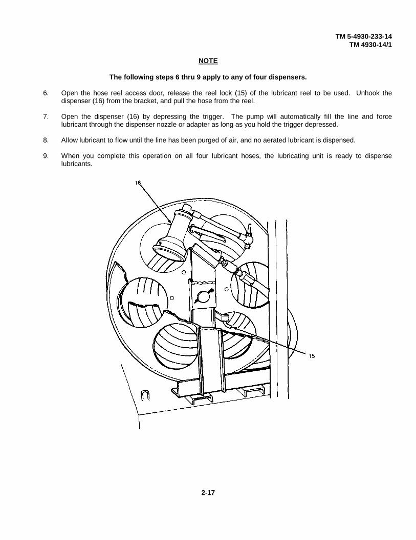
NOTE
The following steps 6 thru 9 apply to any of four dispensers.
6. Open the hose reel access door, release the reel lock (15) of the lubricant reel to be used. Unhook thedispenser (16) from the bracket, and pull the hose from the reel.
7. Open the dispenser (16) by depressing the trigger. The pump will automatically fill the line and forcelubricant through the dispenser nozzle or adapter as long as you hold the trigger depressed.
8. Allow lubricant to flow until the line has been purged of air, and no aerated lubricant is dispensed.
9. When you complete this operation on all four lubricant hoses, the lubricating unit is ready to dispenselubricants.
2-17
TM 5-4930-233-14TM 4930-14/1
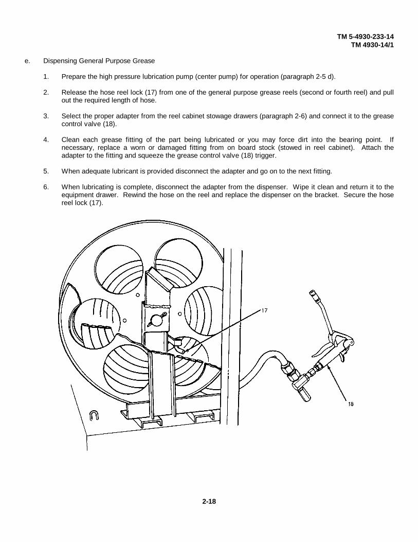
e. Dispensing General Purpose Grease
1. Prepare the high pressure lubrication pump (center pump) for operation (paragraph 2-5 d).
2. Release the hose reel lock (17) from one of the general purpose grease reels (second or fourth reel) and pullout the required length of hose.
3. Select the proper adapter from the reel cabinet stowage drawers (paragraph 2-6) and connect it to the greasecontrol valve (18).
4. Clean each grease fitting of the part being lubricated or you may force dirt into the bearing point. Ifnecessary, replace a worn or damaged fitting from on board stock (stowed in reel cabinet). Attach theadapter to the fitting and squeeze the grease control valve (18) trigger.
5. When adequate lubricant is provided disconnect the adapter and go on to the next fitting.
6. When lubricating is complete, disconnect the adapter from the dispenser. Wipe it clean and return it to theequipment drawer. Rewind the hose on the reel and replace the dispenser on the bracket. Secure the hosereel lock (17).
2-18
TM 5-4930-233-14TM 4930-14/1
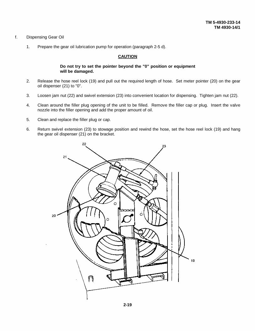
f. Dispensing Gear Oil
1. Prepare the gear oil lubrication pump for operation (paragraph 2-5 d).
CAUTION
Do not try to set the pointer beyond the "0" position or equipmentwill be damaged.
2. Release the hose reel lock (19) and pull out the required length of hose. Set meter pointer (20) on the gearoil dispenser (21) to "0".
3. Loosen jam nut (22) and swivel extension (23) into convenient location for dispensing. Tighten jam nut (22).
4. Clean around the filler plug opening of the unit to be filled. Remove the filler cap or plug. Insert the valvenozzle into the filler opening and add the proper amount of oil.
5. Clean and replace the filler plug or cap.
6. Return swivel extension (23) to stowage position and rewind the hose, set the hose reel lock (19) and hangthe gear oil dispenser (21) on the bracket.
2-19

TM 5-4930-233-14TM 4930-14/1
g. Dispensing Engine Oil
1. Prepare the engine oil lubrication pump for operation (paragraph 2-5 d).
CAUTION
Do not try to set the pointer beyond the "0" position or equipmentwill be damaged.
2. Release the hose reel lock (24), remove the engine oil dispenser (25) from the bracket, and pull out thedesired amount of hose.
3. Set the meter pointer (26) on the dispenser (25) to "0".
4. Clean around the filler plug. Remove filler plug, insert nozzle, and fill reservoir to proper level. Quantity willbe indicated on the engine oil dispenser (25).
5. Clean and replace plug. Rewind hose, set hose reel lock (24), and return dispenser (25) to bracket.
2-20

TM 5-4930-233-14TM 4930-14/1
h. Use of Air Chuck
1. Release reel lock (27) and unwind hose as required.
2. Place auxiliary equipment onto quick disconnect (28).
WARNING
Do not use compressed air for blowing dirt from your clothing orskin. Air can enter body openings and cause severe injury ordeath. Avoid horseplay with compressed air.
3. After air service operations have been performed, rewind the air hose onto reel and lock. Remove auxiliaryequipment from quick disconnect (28) and remove to stowage.
i. Shutdown Procedures
1. Stop the engine (paragraph 2-5 b).
2. Open air drain valve to completely vent air pressure by turning lever (6).
2-21

TM 5-4930-233-14TM 4930-14/1
2-6. OPERATION OF AUXILIARY EQUIPMENT
a. Suction Gun (1). You can use the suction gun to empty or fill transmissions, differentials, or any part of avehicle that requires emptying, other than by draining through a bottom outlet. Fill the suction gun byinserting the nozzle into the oil or fluid. Pull out the handle as far as it will go. When you use the suction gunfor filling purposes, it is operated by inserting the nozzle in the oil hole. Push the handle forward until asufficient quantity of oil has been delivered. When you use the suction gun for draining purposes, it isoperated by inserting the nozzle into the drain hole of the housing. Pull out the suction gun handle as far asit will go, and a gun full of fluid can be removed. To empty, you must remove the nozzle from the drain holeand push in the handle as far as it will go.
b. Hacksaw Frame and Blade (2). The hacksaw frame and blade, for use in cutting hose when replacingreusable hose and fittings.
c. Hand Lever Grease Gun (3). Use the high-pressure hand lever gun for dispensing lubricants in smallquantities, or for dispensing special lubricants. When you operate the hand lever gun, you will get bestresults by taking full strokes with the lever handle. If you are using a heavy lubricant, it may be necessary toprime the lever gun occasionally. Special couplers and adapters provide adaptation to all types of fittings.To fill the lever gun, proceed as follows:
(1) Unscrew head and lever from cylinder.(2) Engage follower and push into a full stop.(3) Place open end of the cylinder into lubricant approximately 2 inches.(4) If barrel is not completely full, pack tightly by hand to eliminate air pockets.(5) Replace head and lever assembly.
2-22
TM 5-4930-233-14TM 4930-14/1
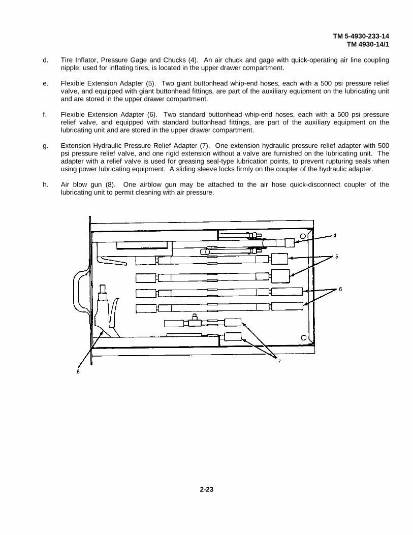
d. Tire Inflator, Pressure Gage and Chucks (4). An air chuck and gage with quick-operating air line couplingnipple, used for inflating tires, is located in the upper drawer compartment.
e. Flexible Extension Adapter (5). Two giant buttonhead whip-end hoses, each with a 500 psi pressure reliefvalve, and equipped with giant buttonhead fittings, are part of the auxiliary equipment on the lubricating unitand are stored in the upper drawer compartment.
f. Flexible Extension Adapter (6). Two standard buttonhead whip-end hoses, each with a 500 psi pressurerelief valve, and equipped with standard buttonhead fittings, are part of the auxiliary equipment on thelubricating unit and are stored in the upper drawer compartment.
g. Extension Hydraulic Pressure Relief Adapter (7). One extension hydraulic pressure relief adapter with 500psi pressure relief valve, and one rigid extension without a valve are furnished on the lubricating unit. Theadapter with a relief valve is used for greasing seal-type lubrication points, to prevent rupturing seals whenusing power lubricating equipment. A sliding sleeve locks firmly on the coupler of the hydraulic adapter.
h. Air blow gun (8). One airblow gun may be attached to the air hose quick-disconnect coupler of thelubricating unit to permit cleaning with air pressure.
2-23

TM 5-4930-233-14TM 4930-14/1
i. Buttonhead Fittings (9). Nine standard and nine giant buttonhead fittings, to be used as replacement parts,are located in the upper drawer compartment.
j. Straight Hydraulic Fittings (10). Twelve straight hydraulic fittings, to replace defective fittings of varyingsizes, are located in the upper drawer compartment.
k. Forty-five Degree Hydraulic Lubrication Fittings (11). Twelve 45 hydraulic fittings, to replace defectivefittings it necessary, are located in the upper drawer compartment.
I. Easy-Out Tool (12). Two easy-out tools are used for removing grease fittings. They are located in the upperdrawer compartment.
m. Plug (13). Three plugs are used to plug hydraulic lines after disconnection.
n. Quick-Disconnect Air Line Couplings (14). One female and three male lube hose repair couplings arelocated in the upper accessory drawer compartment.
o. High Pressure Hose End Fittings (15). Six female swivel and six male lube hose repair couplings are locatedin the upper accessory drawer compartment.
p. Air Hose End Fittings (16). Three each male and female reusable hose end fittings of 1/4-inch insidediameter air hoses are located in the upper drawer compartment.
q. Straight and Z-Swivel Adapters (17). A straight and a Z-swivel adapter are used to connect the controlvalves to the supply hoses, thus permitting the valve to swivel for easy access to hard-to-reach fittings. Theswivel adapters are located in the upper drawer compartment.
2-24

TM 5-4930-233-14TM 4930-14/1
r. Oil Spray Gun
1. General. Use the air-operated oil spray gun (18) to obtain oil spray at high pressures. The gunconsists of an oil spray container and a head with an air valve. Separate controls, adjust the inputquantity of air and the quantity of air ejected. An adjustable nozzle permits either a stream, or spraytype oil ejection.
2. Operation. Fill the container with the desired grade of oil. Screw the container into the head. Attachthe air line coupler of the spray gun to the air hose quick-disconnect coupler on the lubricating unit.Turn the adjustable nozzle to the closed position. Press the air valve button until desired amount of oilejection is obtained.
s. Hand Oiler (19). Operate the hand oiler by squeezing the trigger. You can use it for applying smallquantities of oil to friction points.
2-25
TM 5-4930-233-14TM 4930-14/1
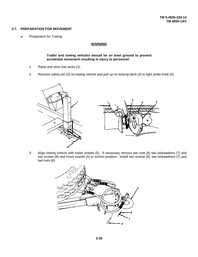
2-7. PREPARATION FOR MOVEMENT
a. Preparation for Towing
WARNING
Trailer and towing vehicles should be on level ground to preventaccidental movement resulting in injury to personnel.
1. Raise and stow rear jacks (1).
2. Remove safety pin (2) on towing vehicle and pull up on locking latch (3) to light pintle hook (4).
3. Align towing vehicle with trailer lunette (5). If necessary remove two nuts (6) two lockwashers (7) andtwo screws (8) and move lunette (5) to correct position. Install two screws (8), two lockwashers (7) andtwo nuts (6).
2-26

TM 5-4930-233-14TM 4930-14/1
a. Preparation for Towing (continued)
4. Back towing vehicle in front of lunette (5). Using the front jackleg, raise lunette (5) and back towingvehicle until pintle hook (4) is directly under lunette. Lower onto pintle hook.
5. Push down and close pintle hook (4). Check that locking latch (3) is locked by pulling up on hookupper jaw of pintle hook (4). Insert safety pin (2).
CAUTION
Safety chains are crossed under lunette to support drawbar in theevent that the trailer detaches from the towing vehicle. Be sure tohave enough slack to allow trailer to make full turns.
6. Cross two safety chains (6) and (7) under lunette (5) and hook on towing vehicle. Secure chains toprevent dragging.
NOTE
Be sure to check tag markings on hose assemblies both on thetrailer and towing vehicle before connecting.
7. Connect both service brake (8) and emergency brake (9) hose assemblies to the towing vehicle. Opentowing vehicle shutoff valves (refer to towing vehicle operator's manual). Apply towing vehicle airbrakes to pressurize air brake system.
8. Connect either 12 Vdc connector (10) or 24 Vdc connector (11) to towing vehicle electrical receptacle.
9. Raise front jack leg (12) to stowed position.
2-27
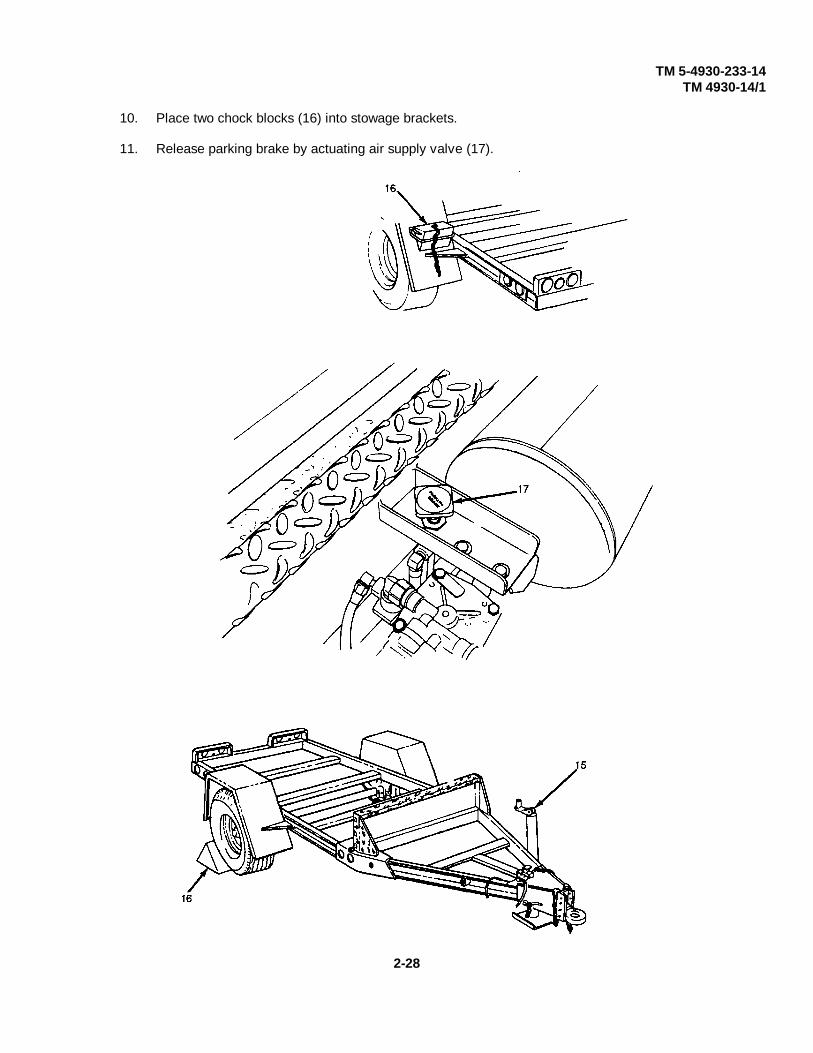
TM 5-4930-233-14TM 4930-14/1
10. Place two chock blocks (16) into stowage brackets.
11. Release parking brake by actuating air supply valve (17).
2-28
TM 5-4930-233-14TM 4930-14/1
b. Driving
CAUTION
Sudden stops may cause the drawbar to bend or buckle.
1. When trailer is attached always start and stop the towing vehicle slowly and gradually. Do this whetheror not the trailer is loaded.
2. Never exceed the maximum speed of 50 mph (80 kph) on highways and 10 mph (16 kph) for crosscountry use.
3. When driving the towing vehicle and trailer, overall length of the unit must be kept in mind whenturning and passing other vehicles. Because the unit is hinged in the middle, turning and backing arealso affected. Heavier payloads will increase stopping distance and decrease off roadmaneuverability.
4. When turning corners, allow for the fact that the trailer wheels turn inside the turning radius of thetowing vehicle. To make a right turn at a road intersection, drive the towing vehicle part way into theintersection and then cut sharply to the right. This will allow for the turning radius of the trailer andkeep it off the cub.
5. Always back the towing vehicle slowly and gradually. Whenever possible, the assistant driver oranother person will act as a ground guide to assist and direct the driver.
6. When backing, the rear of the trailer will move in the opposite direction in which the towing vehicle isturned. When the towing vehicle is turned to the right, the rear of the trailer will go left. When thetowing vehicle has turned and backing in a straight line is required, turn the towing vehicle in thedirection the trailer is moving. This will slowly bring the towing vehicle and trailer into a straight line.
7. In normal operation the brakes of the towing vehicle and trailer are applied at the same time when thedriver steps on the brake pedal. Brake pressure must be applied gradually and smoothly. With sometowing vehicles the trailer brakes can be applied separately by using a brake control (refer to towingvehicle operator's manual). On steep grades or slippery surfaces, the trailer brakes should be appliedbefore the towing vehicle brakes, if possible. This will reduce the possibility of jackknifing the trailer.
8. When the towing vehicle and trailer are to be left unattended, set the towing vehicle parking brake, turnoff the engine and set the chock blocks.
c. After towing
1. Lower front jack leg (15).
2. Position two chock blocks (16) behind wheels.
2-29

TM 5-4930-233-14TM 4930-14/1
3. Disconnect either 12 Vdc connector (13) or 24 Vdc connector (14) from towing vehicle.
WARNING
Trailer wheels must be chocked even if parking brake is applied.The parking brake will release within 1-1/2 hours and if notcorrectly chocked the trailer may roll causing severe personalinjury or death.
4. Apply parking brake by activating air supply valve (17).
5. Disconnect both service brake (11) and emergency brake (12) hose assemblies from the towingvehicle. Stow in two brackets (18).
6. Unhook two safety chains (9 and 10) from towing vehicle.
2-30

TM 5-4930-233-14TM 4930-14/1
7. Remove safety pin (2) on towing vehicle and pull up on locking latch (3) to lift pintle hook (4).
8. Using the front backleg, lift lunette (5) off of pintle hook (4). Slowly move towing vehicle forward toclear lunette (5).
9. Push down and close pintle hook (4). Check that locking latch (3) is locked by pulling up on pintle hook(4). Insert safety pin (2).
10. Lower rear jacks (1) and adjust with front jackleg to provide a level, stable base for lubrication andservicing operations.
2-31
TM 5-4930-233-14TM 4930-14/1
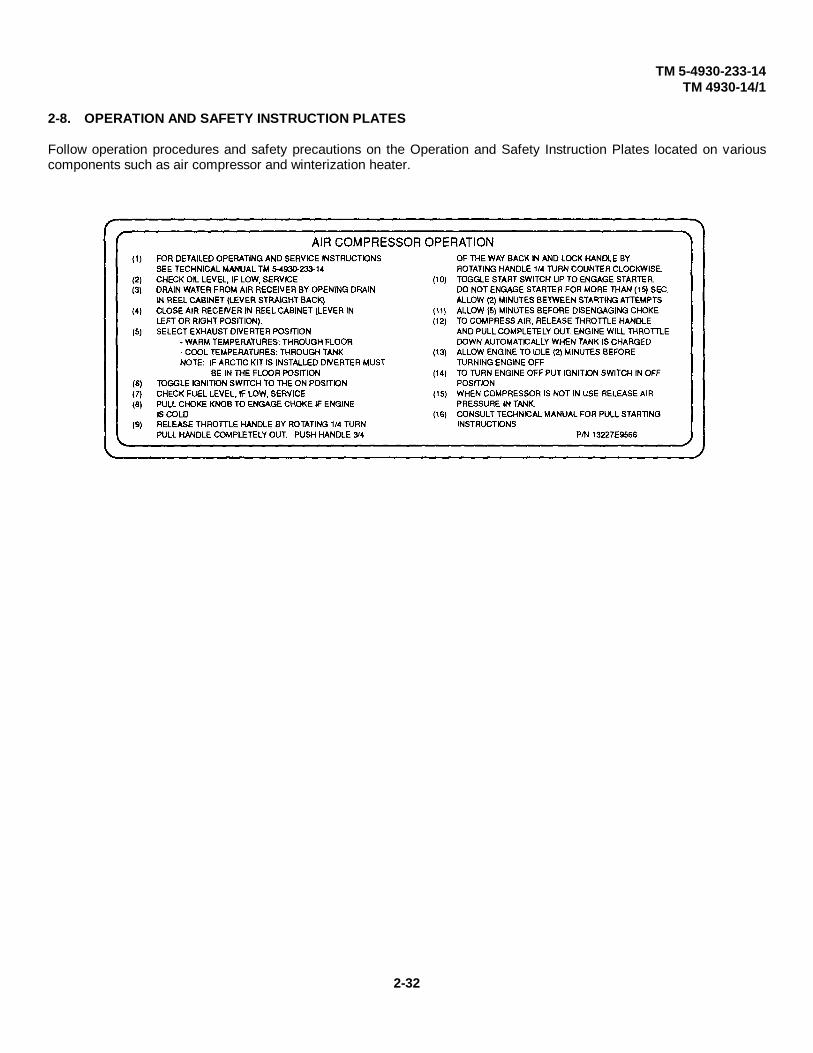
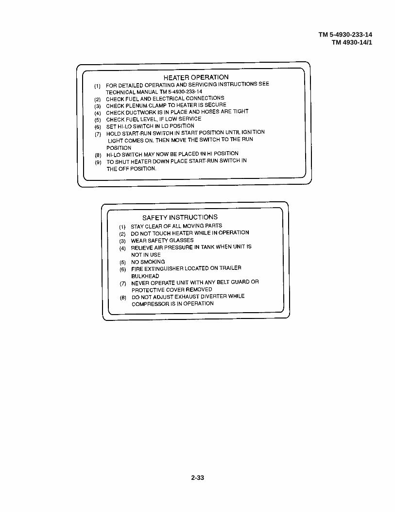
2-8. OPERATION AND SAFETY INSTRUCTION PLATES
Follow operation procedures and safety precautions on the Operation and Safety Instruction Plates located on variouscomponents such as air compressor and winterization heater.
2-32
TM 5-4930-233-14TM 4930-14/1
2-33

TM 5-4930-233-14TM 4930-14/1
Section IV. OPERATION UNDER UNUSUAL CONDITIONS
2-9. OPERATION IN EXTREME COLD
a. General. You will have to take special precautions when operating the lubricating and servicing unit inextremely cold temperatures. Lubrication, fuel, oil, electrical and compressed air systems, and care oflubricants are all affected by cold weather operations.
b. Care of Lubricants. Keep lubricants in tightly closed containers and, if possible, in a protected place to insureease of handling. You must remove all snow and ice from the containers before opening them to transferlubricants to lubricant tanks or to guns.
c. Lubrication. During the cold weather, lubricants that are too heavy will make your vehicle hard to start anddifficult to operate. This will also cause rapid wear of the moving parts.
d. Electrical System. The large surges of electrical current required to start a cold engine demand goodelectrical contacts. Inspect, clean, and tighten all connections, especially battery terminals.
e. Fuel Systems. In cold weather, condensation of moisture in the air will cause water to accumulate on tools,in drums and containers. This water will freeze and form ice crystals, which clog fuel lines and carburetorjets unless the following precautions are taken.
1. Use filter paper or other approved strainer when you fill the fuel tank or when you transfer fuel fromone container to another.
2. Remove snow or ice from the fuel tank filler cap and dispensing equipment before you fill the fuel tank.
3. Keep the filler cap tightened properly to keep moisture and dirt from the tank.
4. After filling or moving a fuel container, allow the fuel to settle before you fill the tank.
5. If possible, keep the fuel tank full when you operate the unit in extremely cold weather. This willprevent condensation of moisture inside the tank.
f. Compressed Air System. Drain accumulated moisture from the compressed air reservoir as often asnecessary. The air reservoir is equipped with an air receiver drain valve that is operated by the levermounted on the reel cabinet assembly. When you open the air receiver drain valve, the water which hascollected at the bottom of the tank will be ejected.
g. Batteries. The batteries installed in the lubricating unit will give satisfactory service in extreme lowtemperatures if you take care of them and keep them fully charged. If the lubricating unit is to remain idle forany long length of time during the cold weather, disconnect the batteries and store them in a warm place.
2-34

TM 5-4930-233-14TM 4930-14/1
h. Cold Engine Starting. Before attempting to start in subzero weather, make certain the consistency of thecrankcase oil is such that the engine can be started. Check the controls to make sure they are free and inoperating condition. When the engine starts, leave the choke partly open until the engine is warmed tooperating temperature, but be careful not to flood the carburetor.
i. Valves. Be extremely careful in operating all valves as they can be easily damaged in low temperatures.
j. Exhaust Heat Diverter. The engine exhaust diverter (1) ducts gas either to a heat reservoir beneath thelubricant container or directly to atmosphere. Use as follows:
(1) In cold weather, operate the engine exhaust diverter (1) to duct exhaust gas to the heat reservoir.
(2) Start the engine (para 2-5) and dose all doors and panel vents on the lubricating unit.
(3) Allow the engine to run for about 10 minutes with the air receiver drain valve lever (2) in open position.
(4) Close the air receiver drain valve (2); wait until the compressor unloads before using the lubricantpump.
(5) Maintain control of lubricant temperature by opening and dosing the engine exhaust diverter (1) asrequired.
NOTE
If the winterization assembly is to be used, the exhaust divertershould be in the floor position.
Change 1 2-35

TM 5-4930-233-14TM 4930-14/1
k. Alcohol Injector. Use the alcohol injector when temperature is below 32°F (0°C). The injector is used toinject alcohol into the air line leading to the pump to prevent condensate freezeup. The alcohol injector isequipped with an 8-ounce capacity metal bowl and a needle valve which controls the flow of alcohol.Operate as follows:
(1) Shut down the unit (para 2-5).
(2) Service alcohol injector (para 3-5).
(3) Start engine (para 2-5).
(4) Turn adjusting screw (1) approximately one-quarter turn.
(5) During operation, inspect sight gage (2), frequently and refill when necessary.
I. Operation of Winterization Assembly.
NOTE
Exhaust diverter should be placed in the floor position ifwinterization assembly is to be used.
(1) Set HI-LO switch (1) in LO position.
(2) Hold Start-Run switch (2) in Start position until ignition light (3) comes on. Then move switch (2) toRun position.
(3) HI-LO switch (1) may now be placed in HI position.
(4) To shut down heater place Start-Run switch (2) in Off position.
2-36
TM 5-4930-233-14TM 4930-14/1
m. Towing in Extreme Cold.
1. Be careful when placing the trailer in motion after a shutdown. Congealed lubricants can cause partfailure.
2. Tires may be frozen to the ground or have a flat spot if they were underinflated.
3. Brake shoes may be frozen to the drums and will require preheating to avoid damage.
4. Refer to FM 9-207 and FM 21-305 for special instructions on driving hazards in snow and ice that maybe encountered during extremely cold weather conditions.
n. At-Halt Parking.
1. For short shutdown periods, park in a sheltered spot out of the wind.
2. For long shutdown periods, if high, dry ground is not available, prepare a footing of planks or brush.
3. Remove all built up ice and snow as soon as possible after shutdown.
2-10. OPERATION IN EXTREME HEAT.
When operating in extremely high temperature, efficient cooling and adequate lubrication of the engine and aircompressor is vitally important. The cooling system must be checked frequently to make sure the air circulation isnot impaired. Give special attention to the engine shrouds and fins for cleanliness. Inspect the carburetor aircleaner frequently. Lubricate more frequently than specified in the lubrication instructions (para 3-2).
2-11. OPERATION IN DUSTY OR SANDY AREAS.
Operation of the lubricating and servicing unit in sandy or dusty areas will require more frequent inspections andlubrication of the unit. Fine sand can penetrate into bushings and bearings. Remove accumulations of sand anddirt at frequent intervals. Inspect the engine and compressor shroud and fins for clogging or impairment of aircirculation. Check the fuel system and take all necessary precautions to prevent sand from entering the fuel tank.During shutdown periods, fasten all housing doors securely.
2-12. OPERATION UNDER RAINY OR HUMID CONDITIONS.
Operation of the lubricating and servicing unit under rainy or humid conditions requires that special attention begiven to exposed machined parts. A thin coat of oil should be applied to all exposed machined parts to keep themas free of moisture as possible. High moisture content in the air may cause difficulty in the electrical system. Thespark plug, magneto, and wiring can become unserviceable due to high humidity. Clean and dry affected parts atfrequent intervals.
2-37
TM 5-4930-233-14TM 4930-14/1
2-13. OPERATION IN SALT WATER AREAS.
In salt water areas, give special attention to general maintenance of the lubricating and servicing units to preventcorrosion of these metal parts. Keep a thin coat of oil on all exposed machined parts, and keep as clean and freeof moisture as possible. Make sure all unpainted spots are painted or coated with approved preventivecompounds. When equipment has been exposed to salt water, steam clean or wash exposed areas with clean,fresh water as soon as possible; dry thoroughly.
2-14. OPERATION IN HIGH ALTITUDES.
The air pressure above sea level decreases as altitude is increased. The result is a decrease in air pressure to thecarburetor causing a too rich gasoline air mixture. If this condition interferes with the operation of the unit, adjustthe carburetor in accordance with instructions provided in TM 9-2805-262-14.
2-15. FORDING.
a. Do not drive the trailer through more than 30 inches of water. Clean, inspect and lubricate immediately afterfording or when the tactical situation permits.
b. If fording operations are required, move fuel cap valve to fording position as instructed on cap.
2-38
TM 5-4930-233-14TM 4930-14/1
Chapter 3
OPERATOR'S MAINTENANCE INSTRUCTIONS
Section I. LUBRICATION INSTRUCTIONS
3-1. GENERAL
a. Keep all lubricants in closed containers and store in a clean, dry place away from external heat. Allow nodust, dirt or other foreign material to mix with the lubricants. Keep all lubrication equipment clean and readyto use.
b. Keep all external parts not requiring lubrication free of lubricants. Before lubricating the equipment wipe alllubrication points free of dirt and grease. Clean all lubrication points after you lubricate them to preventaccumulation of dirt.
c. Intervals are based on normal hours of operation. Change the interval if your lubricants are contaminated orif you are operating the equipment under adverse operating conditions, including longer-than-usual operatinghours. You may extend the interval during times of low activity, but you must take adequate preservationprecautions.
d. Lube all points after fording operations.
e. Lube points shown by dotted arrow on both sides of the equipment.
f. The lowest level of maintenance authorized to lube a point is indicated by one of the following: (C)Operator/Crew.
g. Service engine in accordance with TM 9-2805-262-14.
3-2. LUBRICATION INSTRUCTIONS
a. Skid Sub Assembly
1. Remove air compressor oil fill plug. Fill compressor crankcase up to high level mark on the oil hole.
2. Run the compressor long enough to warm the crankcase oil. Place suitable container under oil drainhole and remove drain plug. Re-install drain plug and fill crankcase up to high level mark on the oilhole, approximately one quart (0.95 liter).
3. Coat reel cabinet drawer rails so operation is smooth, when drawers are pulled out.
4. Coat reel assembly at bracket so the rotation is smooth.
5. OIL CAN POINTS. Every 50 hours lubricate devises, control linkages, and all exposed adjustingthreads with OE.
NOTE
THESE LUBRICATION INSTRUCTIONS ARE MANDATORY.
3-1
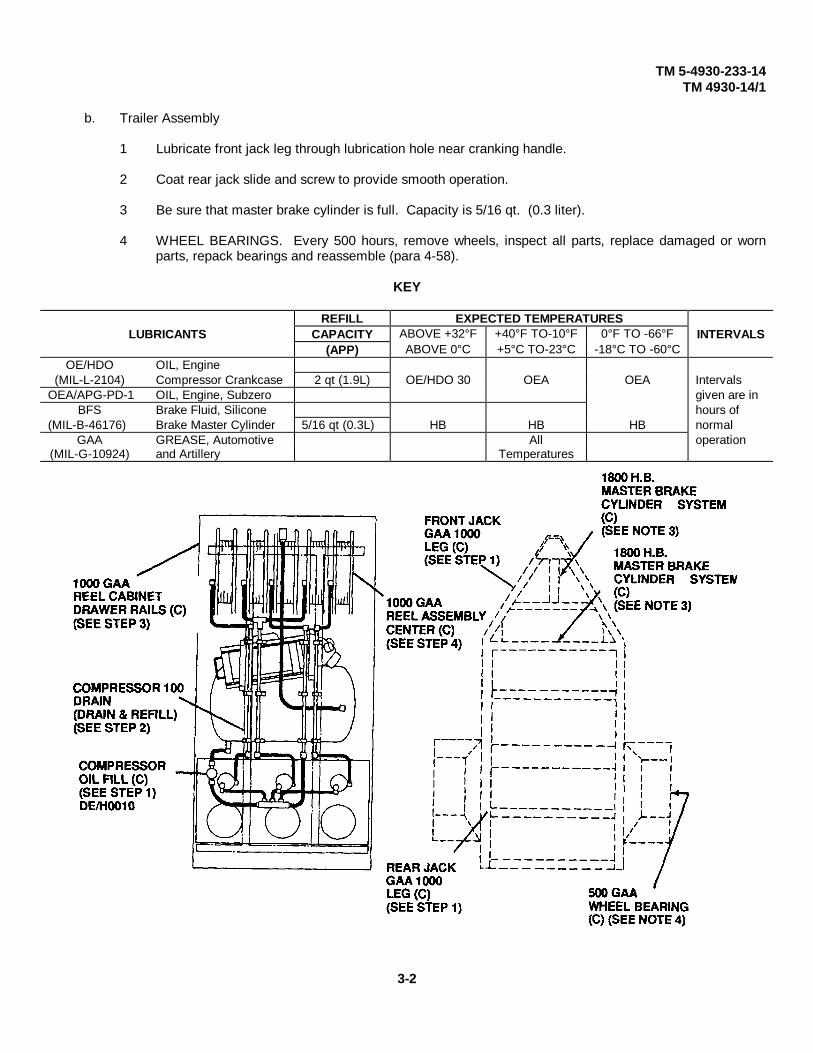
TM 5-4930-233-14TM 4930-14/1
b. Trailer Assembly
1 Lubricate front jack leg through lubrication hole near cranking handle.
2 Coat rear jack slide and screw to provide smooth operation.
3 Be sure that master brake cylinder is full. Capacity is 5/16 qt. (0.3 liter).
4 WHEEL BEARINGS. Every 500 hours, remove wheels, inspect all parts, replace damaged or wornparts, repack bearings and reassemble (para 4-58).
KEY
REFILL EXPECTED TEMPERATURESLUBRICANTS CAPACITY ABOVE +32°F +40°F TO-10°F 0°F TO -66°F INTERVALS
(APP) ABOVE 0°C +5°C TO-23°C -18°C TO -60°COE/HDO OIL, Engine
(MIL-L-2104) Compressor Crankcase 2 qt (1.9L) OE/HDO 30 OEA OEA IntervalsOEA/APG-PD-1 OIL, Engine, Subzero given are in
BFS Brake Fluid, Silicone hours of(MIL-B-46176) Brake Master Cylinder 5/16 qt (0.3L) HB HB HB normal
GAA GREASE, Automotive All operation(MIL-G-10924) and Artillery Temperatures
3-2

TM 5-4930-233-14TM 4930-14/1
Section II. OPERATOR TROUBLESHOOTING
3-3. INTRODUCTORY INFORMATION
a. This section provides information useful in diagnosing and correcting unsatisfactory operation or failure ofthe lubrication and service unit. Each malfunction is followed by a list of probable causes and actions to taketo remedy the malfunction. You should perform the tests/inspections and corrective action in the order listed.
b. This manual cannot list all malfunctions that may occur; nor all tests or inspections and corrective actions. Ifa malfunction is not listed or is not corrected by listed corrective actions, notify your supervisor.
3-3
TM 5-4930-233-14TM 4930-14/1
Table 3-1. Operator's Troubleshooting
ITEM
MALFUNCTION
TEST OR INSPECTION
CORRECTIVE ACTION
1. ENGINE FAILS TO TURN OVER WHEN STARTER SWITCH IS PUSHED
WARNING
Do not smoke or use an open flame in the vicinity when servicingthe batteries. Batteries generate hydrogen gas, which can explodecausing severe injury or even death.
Step 1. Check to see if batteries electrolite level is over plates.
Add distilled water until level is correct.
Step 2. Inspect for loose, corroded or broken battery cables.
Clean corroded cables. Tighten loose connections. If cables are broken or damaged, notify unitmaintenance.
Step 3. Inspect air compressor wiring harness for damage or loose connections.
Tighten loose connections. If wiring harness is damaged or broken, notify unit maintenance.
Step 4. Inspect control panel switches for damage.
Notify unit maintenance if switches are damaged.
Step 5. Inspect starter for damage.
Notify unit maintenance if starter is damaged.
2. ENGINE TURNS OVER BUT FAILS TO START
Step 1. Ensure that control panel switches are in correct position for starting.
Place switches in correct positions (paragraph 2-5).
Step 2. Check for improperly choked engine, especially when engine is cold pull out choke completely.
Step 3. Check for empty fuel tank.
Fill empty fuel tank.
Step 4. Check for damaged or leaking fuel lines.
Notify unit maintenance if fuel lines are damaged or leaking.
3-4

TM 4930-14/1
Table 3-1. Operator's Troubleshooting - Continued
ITEMMALFUNCTION
TEST OR INSPECTIONCORRECTIVE ACTION
Step 5. Check for flooded carburetor, especially if engine is hot.Turn over engine with choke open and throttle open completely.
3. ENGINE STARTS BUT THEN STOPS
Step 1. Check for insufficient fuel supply.Fill fuel tank.
Step 2. Check for pulled out choke control.Push in choke control as engine warms.
Step 3. Check for correct engine oil level (TM 9-2805-262-14).Service engine as required. If oil level is correct, notify unit maintenance.
4. ENGINE OVERHEATS
Check engine oil level (TM 9-2805-262-14).Service engine as required. Notify unit maintenance if engine continues to operate in an overheated condition.
5. ENGINE RUNS BUT LACKS POWER
Step 1. Check that throttle control is in full speed condition.Pull throttle control into full speed condition.
Step 2. Check that choke control is fully open (pushed in) when engine is warm.Push in choke control.
6. COMPRESSOR OVERHEATS
Step 1. Check for dirty cooling fins on intercooler and cylinder.Clean cooling fins.
Step 2. Check for slipping drive belts.Notify unit maintenance if drive belts are slipping or worn.
3-5

TM 5-4930-233-14TM 4930-14/1
Table 3-1. Operator's Troubleshooting - Continued
ITEMMALFUNCTION
TEST OR INSPECTIONCORRECTIVE ACTION
Step 3. Check for dirty air compressor air filter.Replace air filter (paragraph 3-4).
Step 4. Check compressor oil level (paragraph 3-2).Service air compressor as needed.
7. COMPRESSOR PUMPS TOO SLOWLY
Step 1. Check for loose or slipping drive beltsNotify unit maintenance if drive belts are slipping or worn.
Step 2. Check for dirty air filter.Replace air filter (paragraph 3-4).
Step 3. Check compressor oil level (paragraph 3-2).Service air compressor as needed.
8. DRIVE BELTS WEAR RAPIDLY
Check that drive belts are loose or slipping.Notify unit maintenance if drive belts are slipping or worn.
REEL ASSEMBLY
1. ALL DISPENSERS FAIL TO DELIVER LUBRICANT AT NORMAL RATE
Step 1. Check that air pressure gauge reads 140 to 175 psi.If pressure will not build correctly, notify unit maintenance.
Step 2. Check that pressure relief valve and air drain valve are closed.If valves will not properly dose, notify unit maintenance.
Step 3. Check for stiff lubricants due to cold weather.Operate winterization assembly (paragraph 2-9).
3-6

TM 5-4930-233-14TM 4930-14/1
Table 3-1. Operator's Troubleshooting - Continued
ITEMMALFUNCTION
TEST OR INSPECTIONCORRECTIVE ACTION
Step 4. Check for frozen air regulator due to cold weather.Operate alcohol injector (paragraph 2-9).
2. ONE DISPENSER FAILS TO DELIVER LUBRICANT AT NORMAL RATE.
Step 1. Check that lubricant level in lube tank is correct.Fill as required (paragraph 2-5).
Step 2. Check that flow back valve is closed.Close valve.
Step 3. Check dispensing pump air pressure regulator for proper adjustment.Adjust air pressure regulator (paragraph 2-5 c).
Step 4. Check air line to pump for kinks or restrictions.If kinks or restrictions cannot be cleared, notify unit maintenance.
Step 5. Check lubricant line for kinks or restrictions.If kinks or restrictions cannot be cleared, notify unit maintenance.
TRANSFER PUMP
1. PUMP DOES NOT OPERATE
Step 1. Check that air pressure gauge reads 140 to 175 psi.If pressure will not build correctly, notify unit maintenance.
Step 2. Check air lines for leaks or damage.Correct air leaks due to bad connections. Notify unit maintenance if needed.
2. PUMP DELIVERS LITTLE OR NO LUBRICANT
Step 1. Check for lubricant in drum.Move pump to other drum if needed.
3-7
TM 5-4930-233-14TM 4930-14/1
Table 3-1. Operator's Troubleshooting - Continued
ITEMMALFUNCTION
TEST OR INSPECTIONCORRECTIVE ACTION
Step 2. Check lower portion of transfer pump for obstructions.Clean lower portion of transfer pump.
TRAILER ELECTRICAL
1. ALL LAMPS DO NOT LIGHT.
Step 1. Check light switch position on towing vehicle.Place switch in correct position (Towing Vehicle Technical Manual).
Step 2. Check electrical connections on the trailer and towing vehicle.Reconnect all incorrectly connected harnesses.
Step 3. Inspect trailer wiring harness for damage.Notify unit maintenance of damaged wiring harness.
2. ONE OR MORE (BUT NOT ALL) LIGHTS WILL NOT LIGHT
Step 1. Check for damaged or broken electrical leads.Notify unit maintenance.
Step 2. Check for loose or damaged electrical connections.Tighten loose connections. If damaged, notify unit maintenance.
AIR BRAKES
1. AIR BRAKES WILL NOT RELEASE
Step 1. Check position of air supply valve.Release parking brake if set.
Step 2. Check for proper connection of air brake couplers.Connect air brakes correctly (paragraph 2-7).
Step 3. Check towing vehicle controls for correct positions.Place controls in correct positions (Towing Vehicle Technical Manual).
3-8

TM 5-4930-233-14TM 4930-14/1
Table 3-1. Operator's Troubleshooting - Continued
ITEMMALFUNCTION
TEST OR INSPECTIONCORRECTIVE ACTION
Step 4. Check for dirty or worn air brakes couplers.Clean dirty couplers. Notify unit maintenance if worn or damaged.
Step 5. Inspect air brake hoses for damage or leaks.Notify unit maintenance of any damage or leaks discovered.
2. BRAKES GRAB
Check for moisture in air tank.Drain moisture in air tank (paragraph 2-4).
3. NO BRAKES OR WEAK BRAKES
Step 1. Check for proper connection of air brake couplers.Connect air brakes correctly (paragraph 2-7).
Step 2. Check that brake lines are connected to towing vehicle properly.Connect brake lines correctly (paragraph 2-7).
AXLE ASSEMBLY
TIRES ARE EXCESSIVELY SCUFFED OR WORN
Step 3. Check tire pressure.Service tires as required (paragraph 3-6).
Step 4. Check for loose, cracked or broken wheels.Notify unit maintenance if wheels are loose, cracked or broken.
Step 5. Inspect suspension for damage.Notify unit maintenance if suspension is damaged.
3-9

TM 5-4930-233-14TM 4930-14/1
Section III. OPERATOR MAINTENANCE PROCEDURES
AIR COMPRESSOR ASSEMBLY
3-4. AIR FILTER-REPLACE/SERVICE
This task covers:
a. Removal b. Cleaning c. Installation
INITIAL SET-UP:
Materials/PartsDetergent (Item 5, App E)
a. Removal
Warning Deleted
Remove wing nut (1), end cover (2) and filter element (3).
b. Cleaning
Wash filter element in soapy water and allow to dry. Replace if dogged, punctured or in any way damaged.
c. Installation
Install filter element (3), end cover (2) and wing nut (1).
Change 1 3-10
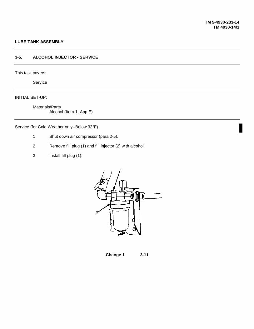
TM 5-4930-233-14TM 4930-14/1
LUBE TANK ASSEMBLY
3-5. ALCOHOL INJECTOR - SERVICE
This task covers:
Service
INITIAL SET-UP:
Materials/PartsAlcohol (Item 1, App E)
Service (for Cold Weather only--Below 32°F)
1 Shut down air compressor (para 2-5).
2 Remove fill plug (1) and fill injector (2) with alcohol.
3 Install fill plug (1).
Change 1 3-11

TM 5-4930-233-14TM 4930-14/1
AXLE ASSEMBLY
3-6. WHEEL AND TIRE - SERVICE
This task covers:
Service
Service
1 Start air compressor (para 2-5).2 Remove tire inflator and pressure gauge (1) from stowage drawer.3 Install inflator (1) on air service hose (2).4 Use tire inflator and pressure gauge (1) to fill tires to 60 psi.5 Return air service hose (2) and tire inflator (1) to stowage.
Change 1 3-12

TM 5-4930-233-14TM 4930-14/1
Chapter 4
UNIT MAINTENANCE INSTRUCTIONS
Section I. REPAIR PARTS, SPECIAL TOOLS, TMDE, AND SUPPORT EQUIPMENT
4-1. COMMON TOOLS AND EQUIPMENT
For authorized common tools and equipment refer to the Modified Table of Organization and Equipment (MTOE) applicable to your unit.
4-2. SPECIAL TOOLS, TMDE, AND SUPPORT EQUIPMENT
No special tools or equipment is required to maintain the lube and servicing unit.
4-3. REPAIR PARTS
Repair parts are listed and illustrated in the repair parts and special tools list (TM 5-4930-233-24P) covering Unit, Direct Support and General Support maintenance for this equipment.
Section II. SERVICE UPON RECEIPT
4-4. CHECK UNPACKED EQUIPMENT
a. Remove any metal strapping, plywood, tapes, seals, wrapping paper or any other shipping material.
WARNING
Clean all parts in a well ventilated area. Avoid inhaling solvent fumesand prolonged exposure of the skin to cleaning solvent. Failure to doso can cause severe injury or DEATH. Do not use near flame orexcessive heat. Flash point of solvent is 100°F to 138°F (38°C to 59°C).
b. If any exterior parts are coated with rust preventative compound, remove it with cleaning solvent (Item6 App. E).
c. Inspect the equipment for damage incurred during shipping. If the equipment has been damaged, report the damage on DD Form 6 Packaging Improvement Report.
d. Check the equipment against the packing slip to see if the shipment is complete. Report all discrepancies in accordance with the instructions of DA PAM 738-750. Marine Corps users refer to MC04430.3.
e. Check to see whether the equipment has been modified.
4-1

TM 5-4930-233-14TM 4930-14/1
4-5. PRELIMINARY SERVICING AND ADJUSTMENT OF EQUIPMENT
a. Perform the preventive maintenance checks and services contained in Table 2-2 and Table 4-1.
WARNING
Do not smoke or use an open flame in the vicinity when servicing thebatteries. Batteries generate hydrogen gas, which is highly explosive.Failure to do so can lead to severe injury or death.
Caustic chemicals in batteries may cause severe bums or blindness ifelectrolyte comes in contact with skin or eyes. To avoid injury, wearsafety protective equipment such as face mask or goggles and gloves.If electrolyte does come in contact with skin or eyes, rinse affectedarea thoroughly with cold water.
b. If you are preparing the unit for initial use, open the container of electrolyte and fill the dry charge batteries so that the electrolyte is up to the required level. If possible, charge the batteries for 10 or 15minutes before connecting and applying the starting load. Make sure you have securely connected thebatteries. Note that the positive lead is marked +. The electrical system has a negative ground.
c. Fill the fuel tank with gasoline. Fuel tank capacity is 10 gallons.
d. Lubricate all points as shown in the lubrication instructions (para 3-2) regardless of interval.e. Schedule the next preventive maintenance checks and services on DD Form 314, Preventive
Maintenance Schedule and Record.
f. Report all deficiencies on DA Form 2404 if the deficiencies appear to involve unsatisfactory design. Marine Corps users report all deficiencies on TM 4700-15/1E.
g. Perform a break-in road test of 25 miles at a maximum speed of 55 miles per hour.
Section III. UNIT PREVENTIVE MAINTENANCE CHECKS AND SERVICES (PMCS)
4-6. GENERAL
a. The best way to maintain vehicles covered by this manual is to inspect the equipment on a regular basis so minor faults can be discovered and corrected before they result in serious damage, failure, or injury. This section contains systematic instructions for inspection, adjustment and correction of vehicle components to avoid costly repairs or major breakdowns. This is Preventive Maintenance Checks and Services (PMCS).
b. All vehicle shortcomings will be reported on DA Form 2404, (DA PAM 738-750). Marine Corps users report all vehicle shortcomings on TM 4700-15/1 E. Equipment Inspection and Maintenance Worksheet, immediately after the PMCS and before taking corrective action. They will also be reported in the equipment log.
c. If something doesn't work, troubleshoot it with the instructions in your manual or notify your supervisor.
d. Always do your PREVENTIVE MAINTENANCE in the same order so it gets to be a habit. Once you've had some practice, you'll spot anything wrong in a hurry.
Change 1 4-2

TM 5-4930-233-14TM 4930-14/1
e. If anything looks wrong, write it on your DA Form 2404. Marine Corps users write it on your TM 4700-15/1 E. If you find something seriously wrong, report it to Direct Support Maintenance RIGHT NOW.
f. When you do your PREVENTIVE MAINTENANCE, take along the tools you will need to make all the checks. Take along a rag, you'll always need at least one.
WARNING
Clean all parts in a well ventilated area. Avoid inhaling solvent fumes andprolonged exposure of the skin to cleaning solvent. Failure to do so can causesevere injury or death. Do not use near flame or excessive heat. Flash point ofsolvent is 100°F to 138°F (38°C to 59°C).
(1) Keep it clean: Dirt, grease, oil and debris only get in the way and may cover up a serious problem. Clean as you work and as needed. Use cleaning solvent (Item 6 App. E) on all metal surfaces. Use soap and water when you clean rubber or plastic material.
(2) Bolts, nuts and screws: Check them all for looseness, missing, bent or broken condition. You can't try them all with a tool of course, but look for chipped paint, bare metal, or rust around bolt heads. If you find one you think is loose, tighten it, or report it to Direct Support Maintenance if you can not tighten it.
(3) Welds: Look for loose or chipped paint, rust or gaps where parts are welded together. If you find a bad weld, report it to Direct Support Maintenance.
(4) Electric wires and connectors: Look for cracked or broken insulation, bare wires and loose or broken connectors. Tighten loose connectors and make sure the wires are in good shape.
(5) Hoses and fluid lines: Look for wear, damage and leaks and make sure clamps and fittings are tight. Wet spots show leaks, of course, but a stain around a fitting or connector can mean a leak. If a leak comes from a loose fitting or connector, tighten it. If something is broken or worn out, report it to maintenance supervisor.
CAUTION
Equipment operation is allowable with minor leakage (Class I or II). Of course,consideration must be given to the fluid capacity in the item/system beingchecked/inspected. When in doubt, NOTIFY YOUR SUPERVISOR!
When operating with Class I or II leaks, continue to check fluid levels as requiredin your PMCS.
Class III leaks should be reported to your supervisor or Direct SupportMaintenance.
4-3

TM 5-4930-233-14TM 4930-14/1
(6) It is necessary for you to know how fluid leakage affects the status of your vehicle. The following are definitions of the types/classes of leakage you need to know to be able to determine the status of your vehicle. Learn, then be familiar with them and REMEMBER WHEN IN DOUBT NOTIFY YOUR SUPERVISOR!
Leakage Definitions for Unit PMCS
Class I Seepage of fluid (as indicated by wetness or discoloration) not great enough to form drops.
Class II Leakage of fluid great enough to form drops but not enough to cause drops to drip from item being checked/inspected.
Class III Leakage of fluid great enough to form drops that fall from the item being checked/inspected.
4-7. PREVENTIVE MAINTENANCE CHECKS AND SERVICE (PMCS) TABLE
EXPLANATION OF COLUMNS
Item No. This column shows the sequence of doing the checks and services and is used to identify the equipment area on the equipment inspection and maintenance worksheet, DA Form 2404.
Interval. This column shows when each check is to be done.
Item To Check/Service. This column shows what items to check and service.
Procedure. This column shows the checks and services to do and how to do them.
Not Fully Mission Capable If. This column lists conditions that would render the equipment unable to perform the mission.
4-4

TM 5-4930-233-14TM 4930-14/1
Table 4-1. Unit PMCS
4-5
(para 3-2).
(para 4-58).
(para 4-22).
(para 4-22).
(para 4-50).
(para
(para4-15).
4-15).

TM 5-4930-233-14TM 4930-14/1
Table 4-1. Unit PMCS - Continued
4-6
(para 4-17).

TM 5-4930-233-14TM 4930-14/1
Section IV. UNIT TROUBLESHOOTING
4-8. INTRODUCTORY INFORMATION
a. This section provides information useful in diagnosing and correcting unsatisfactory operation or failure of lubrication and servicing unit components. Each malfunction is followed by a list of probable causes and actions to take to remedy the malfunction. You should perform the tests/inspections and corrective actions in the order listed.
b. After performing a corrective action always check to see if the malfunction has been corrected. If so, your troubleshooting is complete for that malfunction. If it has not been corrected, continue on with the next corrective action or step.
c. This manual cannot list all malfunctions that may occur; or all tests or inspections and corrective actions. If a malfunction is not listed or is not corrected by listed corrective actions, notify your supervisor.
4-7

TM 5-4930-233-14TM 4930-14/1
Table 4-2. Unit Troubleshooting
ITEMMALFUNCTION
TEST OR INSPECTIONCORRECTIVE ACTION
1. ENGINE FAILS TO TURN OVER
Step 1. Check for weak or dead batteries (para 4-18).Charge or replace batteries (para 4-18).
Step 2. Check for loose, broken or damage on battery cables.Replace or repair cables (para 4-18).
Step 3. Check for defective starter (para 4-23).Replace starter (para 4-23).
Step 4. Test wiring harness (para 4-25).Replace or repair wiring harness (para 4-25).
Step 5. Test starter/ignition switch (para 4-26).Replace switch (para 4-26).
Step 6. Test cold start switch (para 4-26).Replace switch (para 4-26).
2. ENGINE RUNS ROUGH
Step 1. Check fuel for contamination.Clean and drain fuel tank (para 4-16).
Step 2. Troubleshoot engine (TM 9-2805-262-14).
3. BATTERIES NOT CHARGING OR HOLDING CHARGE
Step 1. Check for weak batteries (para 4-18).Replace batteries (para 4-18).
Step 2. Check for missing or loose alternator belt (para 4-22).Replace or adjust belt (para 4-22).
4-8
TM 5-4930-233-14TM 4930-14/1
Table 4-2. Unit Troubleshooting - Continued
ITEMMALFUNCTION
TEST OR INSPECTIONCORRECTIVE ACTION
Step 3. Test wiring harness (para 4-25).Replace or repair harness.
Step 4. Test for defective alternator (para 4-24).Replace alternator (para 4-24).
4. ENGINE CRANKS BUT WILL NOT RUN OR RUNS FOR A SHORT TIME ONLY
Step 1. Check wiring harness for proper connections and test (para 4-25).Correct connections or repair harness as needed (para 4-25).
Step 2. Check fuel strainer and filter for clogging.Replace or clean elements as needed (para 4-16).
Step 3. Test ignition/starter switch (para 4-26).Replace switch (para 4-26).
Step 4. Test relays A and B (para 4-26).Replace defective relay (para 4-26).
Step 5. Disconnect oil pressure switch (para 4-25) and operate engine.Replace oil pressure switch if engine operates correctly.
NOTE
If engine will not run with new oil pressure switch but will operate with switchdisconnected, troubleshoot engine (TM 9-2805-262-14).
Step 6. Disconnect oil temperature switch (para 4-26). Operate engine.Replace oil temperature switch if engine operates correctly
NOTE
If engine will not run with new oil temperature switch but will operate with switchdisconnected, troubleshoot engine (TM 9-2805-262-14).
4-9

TM 5-4930-233-14TM 4930-14/1
Table 4-2. Unit Troubleshooting - Continued
ITEMMALFUNCTION
TEST OR INSPECTIONCORRECTIVE ACTION
5. ENGINE OPERATES WITH OIL PRESSURE BELOW 15 PSI
CAUTION
Troubleshoot engine for low oil pressure along with the steps below. Failureto correct this problem can lead to serious engine damage.
Step 1. Test wiring harness (para 4-25).Replace or repair harness (para 4-25).
Step 2. Replace oil pressure switch.
Step 3. Test oil pressure gauge (para 4-26).Replace oil pressure gauge (para 4-26).
6. WINTERIZATION HEATER DOES NOT OPERATE
Step 1. Inspect wiring harness for damage and test (para 4-42).Repair or replace harness (para 4-42).
Step 2. Test fuel pump (para 4-41).Replace fuel pump (para 4-41).
Step 3. Test control box (para 4-40).Replace control box (para 4-40).
Step 4. Replace heater (para 4-39).
7. COMPRESSOR FAILS TO BUILD UP OR MAINTAIN REQUIRED PRESSURE.
Step 1. Check drive belts for damage or slipping.Adjust or replace drive belts (para 4-22).
Step 2. Check compressor pilot valve for proper adjustment.Adjust pilot valve (para 4-27).
4-10

TM 5-4930-233-14TM 4930-14/1
Table 4-2. Unit Troubleshooting - Continued
ITEMMALFUNCTION
TEST OR INSPECTIONCORRECTIVE ACTION
Step 3. Check for leaks in air compressor tubes, hoses and fittings.Repair leaks as needed.
Step 4. Check for leaking pressure relief valve.Replace pressure relief valve (para 4-28).
8. ONE LUBRICANT DISPENSER SYSTEM FAILS TO DISPENSE AT REQUIRED RATE.
Step 1. Check for faulty air pressure regulator.Replace air regulator assembly (para 4-36).
Step 2. Check for lubricant discharge directly from pump.Replace faulty pump (para 4-37).
Step 3. Check for damaged or leaking lubrication piping.Replace damaged piping and repair any leaks.
Step 4. Check operation of lubricant dispenser.Replace defective dispenser (para 4-19).
9. COMPRESSOR OPERATES AT OVER 175 PSI.
Step 1. Check pilot valve for proper adjustment.Adjust pilot valve (para 4-27).
Step 2. Check air cylinder for damage or binded operation.Replace air cylinder (para 4-30).
10. WHEEL BRAKES FAIL TO APPLY.
Step 1. Check that towing vehicle brake system is operating correctly. (Towing Vehicle Technical Manual) Repair towing vehicle brake system.
4-11

TM 5-4930-233-14TM 4930-14/1
Table 4-2. Unit Troubleshooting - Continued
ITEMMALFUNCTION
TEST OR INSPECTIONCORRECTIVE ACTION
Step 2. Check brake system for leaks or damage.Fix leaks or damage, replacing parts if required.
Step 3. Check for clogged air filter.Replace air filter (para 4-50).
Step 4. Check for improperly adjusted brakes (para 4-58).Adjust brakes (para 4-58).
Step 5. Check for air in the hydraulic system by bleeding the brakes (para 4-58).
11. BRAKES GRAB OR FAIL TO RELEASE
Step 1. Check for moisture in air reservoir.Drain the reservoir.
Step 2. Check brakes for correct adjustment.Adjust as needed (para 4-58).
Step 3. Check for out-of-round, cracked, or damaged brake drum.Notify direct support maintenance.
12. ALL LIGHTS ARE OUT
Step 1. Check towing vehicle light operationTroubleshoot towing vehicle electrical (Towing Vehicle Technical Manual).
Step 2. Test wiring harness (para 4-56).Replace or repair as required (para 4-56).
Step 3. Test junction box (para 4-53).
4-12

TM 5-4930-233-14TM 4930-14/1
Table 4-2. Unit Troubleshooting - Continued
ITEMMALFUNCTION
TEST OR INSPECTIONCORRECTIVE ACTION
13. ONE OR MORE (NOT ALL) LAMPS FAIL TO LIGHT
Step 1. Check towing vehicle light operationTroubleshoot towing vehicle electrical (Towing Vehicle Technical Manual).
Step 2. Inspect wiring for loose connections or damage.Replace or repair as necessary (para 4-56).
Step 3. Test lights that are out (para 4-54 or 4-55).Replace lights as required (para 4-54 or 4-55).
Step 4. Test junction box (para 4-53).Replace junction box (para 4-53).
14. ONE OR MORE CONTROL PANEL GAUGES FAIL TO OPERATE OR GIVE REQUIRED READINGS NOTE
NOTE
Step 1 applies only to Fuel Gauge.
Step 1. Check for fuel in fuel tank.Fill fuel tank
Step 2. Troubleshoot air compressor (Table 4-2, malfunction 7. and 9.).Replace air pressure gauge (para 4-25).
Step 3. Test wiring harness connection to gauge(s).Replace or repair wiring harness (para 4-25).
Step 4. Replace gauge(s) (para 4-25).
4-13
TM 5-4930-233-14TM 4930-14/1
Section V. UNIT MAINTENANCE INSTRUCTIONS
4-9. GENERAL MAINTENANCE
a. This paragraph contains general maintenance instructions which you must observe during removal, disassembly, repair and reassembly of lubrication and servicing unit components.
WARNING
Clean all parts in a well ventilated area. Avoid inhaling solvent fumes andprolonged exposure of the skin to cleaning solvent. Failure to do so cancause severe injury or death. Do not use near flame or excessive heat.Flash point of solvent is 100°F to 138°F (38°C to 59°C)
b. Prior to removing component assemblies, you should thoroughly clean the surrounding area and the exterior surfaces of the unit being removed. Use dry cleaning solvent (Item 6 App. E) for most general cleaning requirements. If assemblies are caked with grease, use a steam cleaner with solvent. Take care to wear protective clothing when degreasing. Clean new components or parts if they are received with a preservative coating.
c. When removing components, always securely block both trailer wheels using trailer chocks. Ifspecial blocking procedures are required for a task, you will find these in the maintenance procedure.
d. When disassembling components, tag and identify any matched or mated parts in the unit so that they can be returned to their original locations or positions when reassembled.
e. Prior to component assembly, make certain that your hands, work bench, assembly tools and parts to be assembled are thoroughly clean. Use clean, lintfree shop cloths or paper towels when necessary to wipe parts.
f. When reassembling components, be sure that you coat moving and sliding parts with a light oil. Also coat packings and oil seal lips with light oil. This reduces the possibility of cutting thepackages and seal lips when installing over sharp edges or threads. Also replace all locking hardware, preformed packing paper or fiber gaskets and any parts that are subject to deterioration or fatigue.
g. If assembly work cannot be completed the same day, cover the assembly and remaining partswith clean cloths or sheet plastic to keep out dust and contaminants which accumulate overnight. Apply a light coat of oil to the remaining parts and clean parts prior to beginning reassembly the following day.
h. After reassembly is completed, reclean the exterior surfaces and check condition of paint. If paint was damaged during reassembly, sand the areas affected and touch up with the correct paint and color. If sanded areas are through the paint and down to bare metal, apply a primercoat and sand lightly before applying final coat. Mask off areas or parts that are not to be painted.
4-14

TM 5-4930-233-14TM 4930-14/1
i. Make certain components are initially greased or filled with oil, so that there is no chance for damage prior to scheduled service of the component. If lubrication is not practical, you shouldtie a warning tag on the equipment indicating unit has been drained and must be serviced before operation.
4-10. GENERAL WIRING REPAIR
Preferred repair methods consists of replacing wires, terminals, connectors, etc., rather than splicing wires, bending endsto form terminals and other make-shift procedures, although the latter may be appropriate for emergency field repairs.Determine the proper size and length of wire, or the terminal, or connector to be used for replacement by referring to the"Wire List" and the wiring diagram included with each electrical wiring harness maintenance procedure.
a. Soldering Connections. Wire connections must be made mechanically sound before they are soldered; solder alone does not provide sufficient strength to prevent breakage. Joining surfaces of connections to be soldered must be clean and bright. If a separate flux is used, it should conform to Specification M IL-F-14256, rosin base flux (Item 7, Appendix E) and should be brushed onto the joint before soldering. If a flux-core solder is used, it should always be rosin-core electrical solder. If an uncored solder is used, is should be a lead-tin solder, (Item 16, Appendix E) conforming to Specification QQ-S-571. Wires should always beheated to the point at which the solder will melt completely and flow into all parts of the joint. Excessive build-up of solder on the joint should be avoided or removed.
b. Insulating Joints. The preferred method of insulating electrical joints is by the use of heat-shrink tubing. To apply, cut a piece of heat-shrink tubing of suitable diameter to a length of 1 inch (2.5 cm) for covering joints at terminals or connectors, or to a length about ½ inch (1.3 cm) longer than the joint to be insulated. Slide the tubing over the wire before making the joint. After the joint is made, slide the tubing so that it covers the joint and shrink in place withmoderate heat.
4-15

TM 5-4930-233-14TM 4930-14/1
ENCLOSURE AND SKID ASSEMBLY
4-11. ENCLOSURE - REPLACE
This task covers:
a. Removal b. Installation
INITIAL SET-UP:
Personnel Required Tools4 General Mechanic’s Tool Box
(Section III, Item 1, App B)
CAUTION
Be certain all controls are pushed in and take care during removal so not to damage lights oncontrol panel.
a. Removal
NOTE
Be sure that all doors are closed.
(1) Turn six thumbscrews (1) to release fuel cap and filler neck assembly (2) from enclosure assembly (3).
(2) Loosen clamp at fuel tank and remove fuel cap and filler neck assembly (2) (para 4-14).
(3) Remove four lifting rings (4), four washers (5) and four rubber washers (6).
(4) Lower rear jacks (para 2-7).
WARNING
All nonessential personnel must be clear of vehicle area to avoid injury.
(5) With a person on each comer, lift enclosure assembly (3) up and off of skid. Place on level surface.
4-16
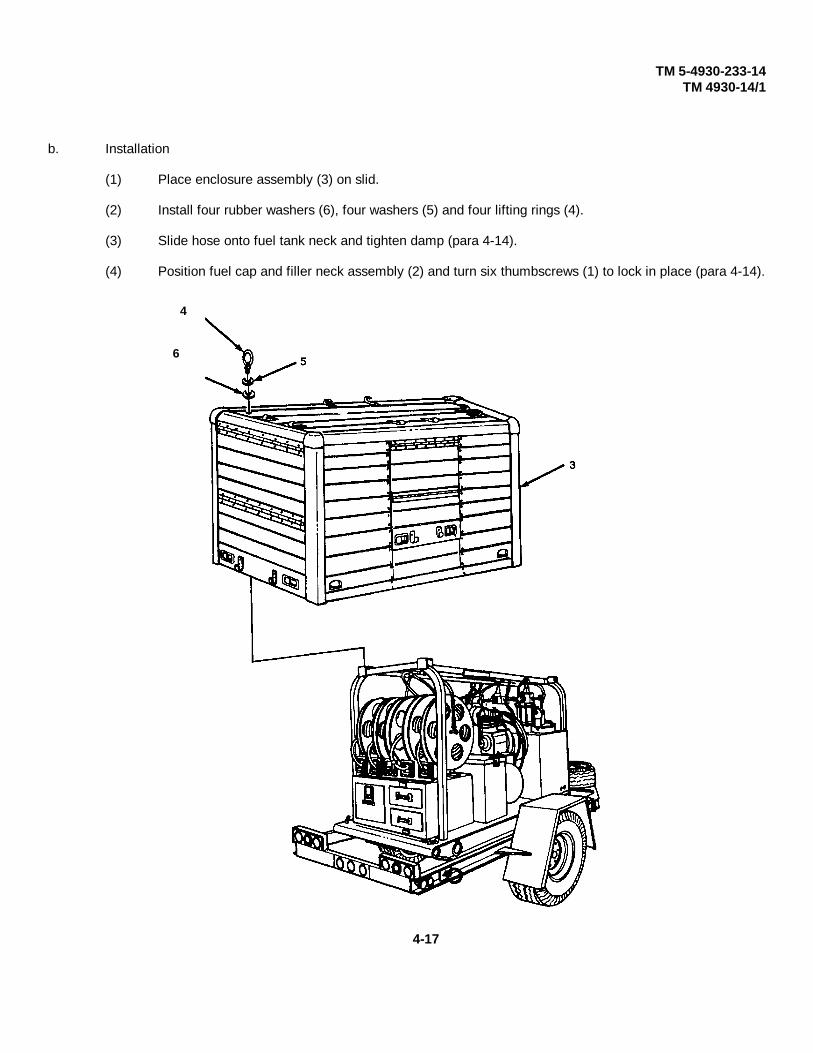
TM 5-4930-233-14TM 4930-14/1
b. Installation
(1) Place enclosure assembly (3) on slid.
(2) Install four rubber washers (6), four washers (5) and four lifting rings (4).
(3) Slide hose onto fuel tank neck and tighten damp (para 4-14).
(4) Position fuel cap and filler neck assembly (2) and turn six thumbscrews (1) to lock in place (para 4-14).
4
6
4-17

TM 5-4930-233-14TM 4930-14/1
ENCLOSURE AND SKID ASSEMBLY
4-12. DOORS - REPLACE
This task covers:
a. Removal b. Installation
INITIAL SET-UP:
Personnel Required Tools4 General Mechanic’s Tool Box
(Section III, Item 1, App B)#1 Common Tool Box
Materials/Parts Drill with 3/16 Drill BitSelf-Locking Nuts (Section III, Item 2, App B)
a. Removal
NOTE
The following procedure applies to any of the four enclosure doors.
(1) Drill out 13 rivets (1) and remove door (2).
(2) Remove eight self locking nuts (3), eight screws (4) and four latch strikers (5). Discard nuts (3).
Change 1 4-18
TM 5-4930-233-14TM 4930-14/1
ENCLOSURE AND SKID ASSEMBLY
4-12. DOORS- REPLACE - (Cont.)
b. Installation
(1) Install four latch strikers (5), eight screws (4) and eight new self-locking nuts (3). Do not tighten nuts (3).
(2) Position door (2) to align 13 rivet holes and support.
(3) Install 13 rivets (1).
(4) Adjust four latch strikers (5) by sliding in or out to ensure that the enclosure door (2) will close tightly.Tighten nuts (3).
4-19

TM 5-4930-233-14TM 4930-14/1
ENCLOSURE AND SKID ASSEMBLY
4-13. PANEL - REPAIRS
This task covers:
Repair
INITIAL SET-UP:
Materials/Parts Equipment ConditionSynthetic rubber caulking Panel Removed
compound (Item 4, App. E)Aluminum sheet, sized
to fit (Item 2, App. E) NOTERivets (MS 24662-203) The following procedure may be used
as required to patch any panel
ToolsGeneral Mechanic’s Tool Box
(Section III, Item 1, App B)
Repair
(1) Straighten any dents and flatten area to be patched.
(2) Cut sheet aluminum patch (1), and shape if necessary to fit.
(3) Drill patch perimeter at a spacing of approx. 2.5 inches (63.5 mm).
(4) Lay patch over damaged area and transfer holes to panel (2).
(5) Coat perimeter of patch with synthetic rubber caulking compound.
(6) Position patch and install with rivets (3) as required.
Change 1 4-20

TM 5-4930-233-14TM 4930-14/1
ENCLOSURE AND SKID ASSEMBLY
4-13. PANELS - REPLACE - (Cont.)
b. Installation
NOTE
Step 3 applies to all panels. For other steps, proceed as needed.
(1) For right rear panel, position storage pocket (8) and install using nine rivets (7).
(2) For front and rear side panels, coat back side of handle (6) with epoxy-polymide primer and install using four rivets (5).
(3) Position panel (4) and install using rivets (3) as necessary. Seal panel along all outside edges with synthetic rubber caulking compound.
(4) For top panel, install eight hooks (2) using rivets (1) as necessary.
4-21

TM 5-4930-233-14TM 4930-14/1
ENCLOSURE AND SKID ASSEMBLY
3-4. AIR FILTER-REPLACE/SERVICE
This task covers:
a. Removal b. Disassembly c. Repaird. Assembly e. Installation
INITIAL SET-UP:
General Safety Instructions ToolsGeneral Mechanic’s Tool Box
WARNING (Section III, Item 2, App B)
Do not use open flame or smoke when workingon the fuel system. An explosion may occur,causing severe injury or death.
a. Removal
(1) Turn six thumbscrews (1) to release fuel cap and filler neck assembly (2).
(2) Loosen clamp (3) at fuel tank (4) and remove fuel cap and filler neck assembly (2).
4-22

TM 5-4930-233-14TM 4930-14/1
ENCLOSURE AND SKID ASSEMBLY
4-14. FUEL CAP AND FILLER NECK ASSEMBLY - REPLACE/REPAIR - (Cont.)
b. Disassembly
(1) Remove fuel cap (5).
(2) Loosen clamp (6) and remove hose (7) from cap housing (8). Slide two clamps (3) and (6) off of hose.
(3) Remove six spring washers (9) and six thumbscrews (1) on housing.
c. Repair
(1) Inspect fuel hose for cracks or deterioration. Replace if necessary.
(2) Replace any part that shows obvious wear or damage.
4-23

TM 5-4930-233-14TM 4930-14/1
ENCLOSURE AND SKID ASSEMBLY
4-14. FUEL CAP AND FILLER NECK ASSEMBLY - REPLACE/REPAIR - (Cont.)
d. Assembly
(1) Install six spring washers (9) and six thumbscrews (1) onto housing.
(2) Slide two clamps (3) and (6) onto hose (7).
(3) Install hose (7) on cap housing (8) and tighten clamp (6).
(4) Install fuel cap (5).
4-24

TM 5-4930-233-14TM 4930-14/1
ENCLOSURE AND SKID ASSEMBLY
4-14. FUEL CAP AND FILLER NECK ASSEMBLY - REPLACE/REPAIR - (Cont.)
e. Installation
(1) Slide hose (7) onto fuel tank neck (4).
(2) Tighten clamp (3).
4-25
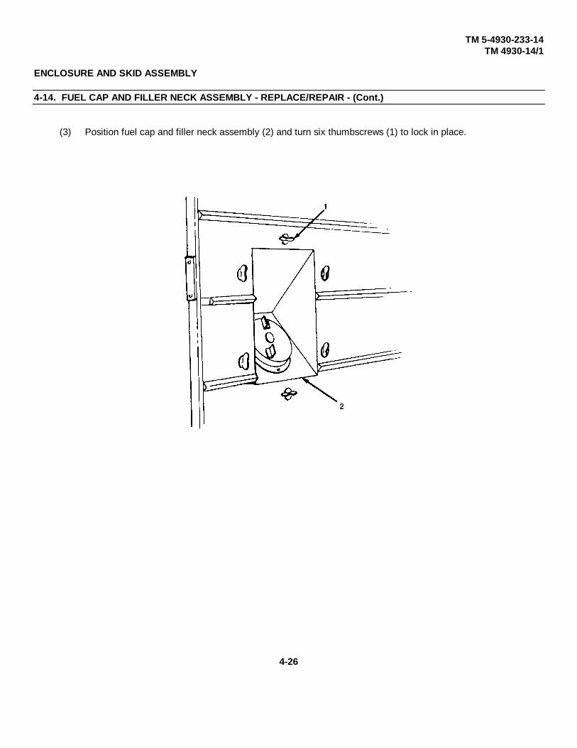
TM 5-4930-233-14TM 4930-14/1
ENCLOSURE AND SKID ASSEMBLY
4-14. FUEL CAP AND FILLER NECK ASSEMBLY - REPLACE/REPAIR - (Cont.)
(3) Position fuel cap and filler neck assembly (2) and turn six thumbscrews (1) to lock in place.
4-26
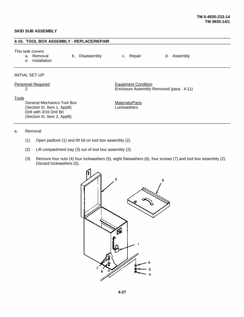
TM 5-4930-233-14TM 4930-14/1
SKID SUB ASSEMBLY
4-15. TOOL BOX ASSEMBLY - REPLACE/REPAIR
This task covers:a. Removal b. Disassembly c. Repair d. Assemblye. Installation
INITIAL SET-UP:
Personnel Required Equipment Condition2 Enclosure Assembly Removed (para. 4-11)
ToolsGeneral Mechanics Tool Box Materials/Parts(Section III, Item 1, AppB) LockwashersDrill with 3/16 Drill Bit(Section III, Item 2, AppB)
a. Removal
(1) Open padlock (1) and lift lid on tool box assembly (2).
(2) Lift compartment tray (3) out of tool box assembly (2).
(3) Remove four nuts (4) four lockwashers (5), eight flatwashers (6), four screws (7) and tool box assembly (2). Discard lockwashers (5).
4-27

TM 5-4930-233-14TM 4930-14/1
SKID SUB ASSEMBLY
4-15. TOOL BOX ASSEMBLY - REPLACE/REPAIR - (Cont.)
b. Disassembly
Drill out rivet (8) from tool box assembly (2) and remove padlock (1).
c. Repair
(1) Inspect tool box assembly (2) for dents. Straighten if possible.
(2) Replace four lockwashers (5).
(3) Replace any damaged parts.
4-28
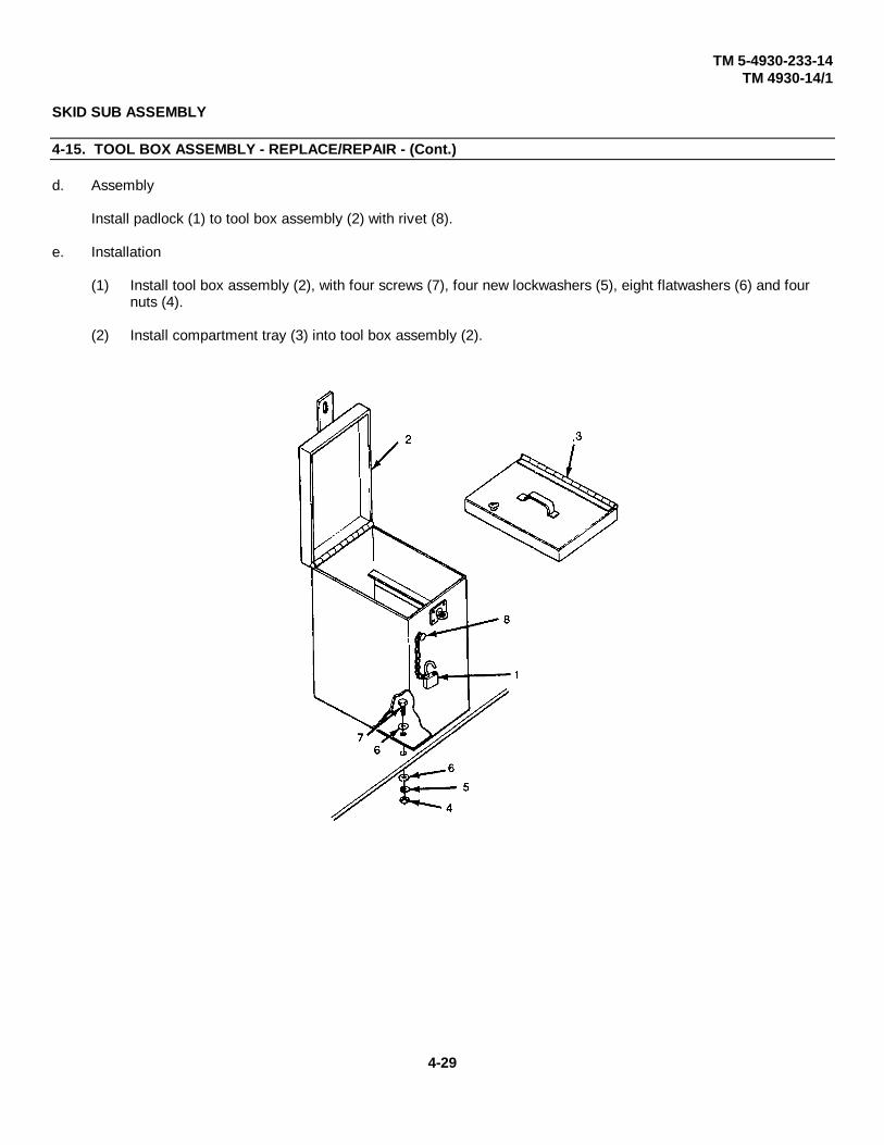
TM 5-4930-233-14TM 4930-14/1
SKID SUB ASSEMBLY
4-15. TOOL BOX ASSEMBLY - REPLACE/REPAIR - (Cont.)
d. Assembly
Install padlock (1) to tool box assembly (2) with rivet (8).
e. Installation
(1) Install tool box assembly (2), with four screws (7), four new lockwashers (5), eight flatwashers (6) and four nuts (4).
(2) Install compartment tray (3) into tool box assembly (2).
4-29
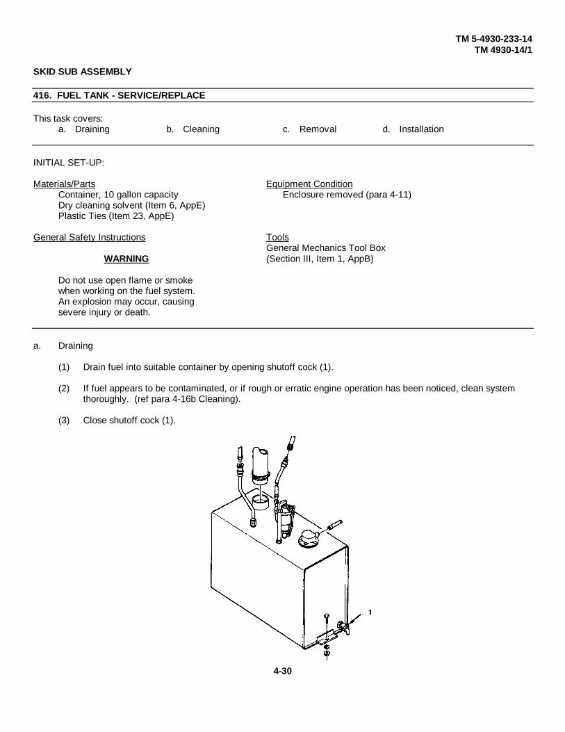
TM 5-4930-233-14TM 4930-14/1
SKID SUB ASSEMBLY
416. FUEL TANK - SERVICE/REPLACE
This task covers:a. Draining b. Cleaning c. Removal d. Installation
INITIAL SET-UP:
Materials/Parts Equipment ConditionContainer, 10 gallon capacity Enclosure removed (para 4-11)Dry cleaning solvent (Item 6, AppE)Plastic Ties (Item 23, AppE)
General Safety Instructions ToolsGeneral Mechanics Tool Box
WARNING (Section III, Item 1, AppB)
Do not use open flame or smokewhen working on the fuel system.An explosion may occur, causingsevere injury or death.
a. Draining
(1) Drain fuel into suitable container by opening shutoff cock (1).
(2) If fuel appears to be contaminated, or if rough or erratic engine operation has been noticed, clean system thoroughly. (ref para 4-16b Cleaning).
(3) Close shutoff cock (1).
4-30

TM 5-4930-233-14TM 4930-14/1
SKID SUB ASSEMBLY
4-16. FUEL TANK - SERVICE/REPLACE - (Cont.)
b. Cleaning
(1) Loosen clamp (2) and slide hose (3) off of fuel tank filler neck (4).
WARNING
Clean all parts in a well ventilated area. Avoid inhalation of solvent fumes andprolonged exposure of the skin to cleaning solvent. Failure to do so can causesevere injury or death. Do not use near flame or excessive heat. Flash point ofsolvent is 100°F (88°C to 59°C).
(2) Remove fuel strainer (5) and clean with dry-cleaning solvent.
(3) Flush out fuel tank (6) with dry-cleaning solvent.
(4) Remove bowl (7) and gasket (8). Clean inside of bowl (7) with dry-cleaning solvent.
(5) Install gasket (8) and bowl (7).
(6) Install fuel strainer (5) and hose (3) onto fuel tank filler neck (4).
(7) Tighten clamp (2).
4-31

TM 5-4930-233-14TM 4930-14/1
SKID SUB ASSEMBLY
4-16. FUEL TANK - SERVICE/REPLACE - (Cont.)
c. Removal
(1) Drain fuel tank (ref para 4-16a Draining).
(2) Disconnect heater fuel hose assembly (9) at quick disconnect and remove plastic ties.
(3) Disconnect engine fuel hose assembly (10) at engine.
(4) Loosen clamp (2) and slide hose (3) off of fuel tank filler neck (4).
(5) Disconnect electrical connector (11) at sending unit.
(6) Remove two nuts (12), two lockwashers (13), two screws (14) and fuel tank assembly (6).
d. Installation
(1) Position fuel tank assembly (6) and install two screws (14), two lockwashers (13) and two nuts (12).
(2) Connect electrical connector (11) at sending unit.
(3) Slide hose (3) onto fuel tank filler neck (4).
(4) Tighten clamp (2).
(5) Connect engine fuel hose assembly (10) at engine.
(6) Connect heater fuel hose assembly (9) at quick disconnect and secure hose to rigid tubing at top of trailer with plastic ties.
4-32

TM 10-4930-233-14TM 4930-14/1
SKID SUB ASSEMBLY
4-16.1. FUEL TANK ASSEMBLY - REPAIR
This task covers:
a. Disassembly b. Repair c. Assembly
INITIAL SET-UP:
GENERAL SAFETY INTRODUCTIONS Equipment ConditionFuel Tank Removed (para 4-16)
WARNING ToolsDo not use open flame or smoke General Mechanics Tool Boxwhen working on the fuel sys- (Section III, Item App B)tem. An explosion may occur,causing severe injury or death.
a. Disassembly
(1) Remove elbow (1) and shutoff cock (2).
(2) Remove five screws (3), five starwashers (4), sending unit (5) and gasket (6).
(3) Remove engine fuel hose assembly (7), elbow (8), fuel filter (9), elbow (10), nipple (11), elbow (12) and nipple (13).
(4) To disassemble fuel hose assembly (7) loosen two damps (14) and remove two hose barbs (15). Slide damps (14) off of hose (16).
(5) Remove heater fuel hose assembly (17). Disassemble by loosening two clamps (18) and removing coupling (19) and two hose barbs (20).
(6) Remove two clamps (18) from hose (21).
(7) Remove fuel strainer (22).
Change 1 4-32.1

TM 10-4930-233-14TM 4930-14/1
4-32.2 Change 1

TM 10-4930-233-14TM 4930-14/1
SKID SUB ASSEMBLY
4-16.1. FUEL TANK ASSEMBLY - REPAIR - (Cont.)
b. Repair
(1) Inspect fuel tank sending unit for cracks, rough or catching movement of the float and for damaged terminals. Replace damaged sending unit.
(2) Inspect hoses and fittings for deterioration or damage. Replace all damaged parts.
c. Assembly
(1) Install fuel strainer (22).
(2) Slide two damps (18) onto hose (21) and install two hose barbs (20) and coupling (19).
(3) Install heater fuel hose assembly (17).
(4) Slide two damps (14) onto hose (16) and install two hose barbs (15). Tighten damps (14).
(5) Install nipple (13), elbow (12), nipple (11), elbow (10), fuel filter (9), elbow (8) and engine fuel hose assembly (7).
(6) Install gasket (6), sending unit (5), five starwashers (4) and five screws (3).
(7) Install shutoff cock (2) and elbow (1).
Change 1 4-32.3

TM 10-4930-233-14TM 4930-14/1
4-32.4 Change 1
TM 1-4930-233-14TM 4930-14/1
REEL CABINET ASSEMBLY
4-17. REEL CABINET ASSEMBLY - REPAIRThis task covers:
a. Disassembly b. Repair c. Assembly
INITIAL SET-UP:
Personnel Required Tools2 General Mechanics Tool Box
(Section III, Item 2, AppB)Drill with 3/16 Drill Bit
Equipment Condition (Section III, Item 2, AppB)Battery box assembly removed (para. 4-18)Reel assemblies removed (para. 4-21)
a. Disassembly
(1) Remove winterization hose and duct (para 4-43)
(2) Drill out rivet (1) and remove padlock and chain (2).
(3) Remove lock bar (3).
(4) Pull out top drawer (4) and remove compartment tray (5).
(5) Remove two screws (6), two lockwashers (7), drawer stop (8) and top drawer (4). Repeat for lower drawer (9).
(6) Disconnect hose (10) at ball valve and air tank and remove hose.
(7) Remove hose (10) by loosening two damps (11). Slide two clamps (11) off of hose (10). Remove two fittings (12).
(8) Remove cotter pin (14) and lever (15) from ball valve (13).
(9) Remove ball valve (13).
(10) Remove grommet (16).
(11) Drill out ten rivets (17) and remove five identification plates (18).
(12) Remove four nuts (19), four lockwashers (20), eight flatwashers (21), four screws (22) and reel cabinet (23).
Change 1 4-33

TM 10-4930-233-14TM 4930-14/1
REEL CABINET ASSEMBLY
4-17. REEL CABINET ASSEMBLY - REPAIR - (Cont.)
b. Repair
(1) Inspect hose (10) for cracks, deterioration, abrasion, cuts, or fraying. Replace if damaged.
(2) Inspect all other parts for damaged threads, cracks, distortion or wear. Replace damaged or worn parts.
4-34 Change 1

TM 10-4930-233-14TM 4930-14/1
REEL CABINET ASSEMBLY
4-17. REEL CABINET ASSEMBLY - REPAIR - (Cont.)
c. Installation
(1) Install reel cabinet (23) with four screws (22), four lockwashers (20), eight flatwashers (21) and four nuts (19).
(2) Position five identification plates (18) and install using ten rivets (17).
(3) Install grommet (16).
(4) Install ball valve (13), lever (15) and cotter pin (14).
(5) Assemble hose (1 0) by sliding two clamps (11) onto hose (10).
(6) Install two fittings (12) and tighten clamps (11).
(7) Connect hose (10) at ball valve (16)and air tank.
(8) Install lower drawer (9), drawer stop (8), two lockwashers (7) and two screws (6). Repeat for top drawer (4).
(9) Store compartment tray (5) in top drawer (4).
(10) Install lock bar (3).
(11) Install padlock and chain (2) using rivet (1).
(12) Lubricate drawer rails (para. 3-2).
(13) Install winterization duct and hose (para. 4-43).
Change 1 4-35

TM 10-4930-233-14TM 4930-14/1
4-36 Change 1

TM 5-4930-233-14TM 4930-14/1
REEL CABINET ASSEMBLY
4-18. BATTERY BOX ASSEMBLY - SERVICE/REPLACE/REPAIR
This task covers:
a. Service b. Removal c. Disassembly d. Repaire. Assembly f. Installation
INITIAL SET-UP:
Materials/Parts General Safety InstructionsDry-cleaning solvent (Item 6, AppE)Heat Shrink tubing (Item 20 and 21 AppE)Grease, GAA (Item 8, AppE)
WARNINGWhen working on batteries, wear
Tools eye protection and remove all jew-General Mechanics Tool Box elry, dogtags and metal items to(Section III, Item 1, AppB) avoid electrical shock and burns.
a. Service
WARNING
Do not smoke or use an open flame in the vicinity when servicing the batteries.Batteries generate hydrogen gas, which is highly explosive and can cause severeinjury or death.
(1) Open battery box assembly drawer (1).
(2) Remove battery caps (2) and check electrolyte level in each cell.
(3) Fill to proper level with distilled water.
(4) Install caps (2) and run engine for 10 to 15 minutes.
(5) Remove caps (2) and check specific gravity for each cell (steps (6) through (9)).
(6) To measure specific gravity, swing plastic cover (3) back on duo-check coolant and battery tester. Clean themeasuring surface (4) and the bottom cover (5) with a clean soft cloth. Close cover.
(7) Use black dipstick (6) to obtain a small sample of battery acid.
(8) Place a few drops of acid onto measuring surface (4) through opening in cover plate.
4-37

TM 5-4930-233-14TM 4930-14/1
REEL CABINET ASSEMBLY
4-18. BATTERY BOX ASSEMBLY - SERVICE/REPLACE/REPAIR - (Cont.)
(9) Point the instrument toward any light source (headlight) and look into eyepiece (7). The battery charge is at a point on the left-hand part of the scale where the dividing line between light and dark (shadow) crosses the scale.
NOTE
A little experience will enable you to quickly obtain the best contrast betweenlight and dark portions of the field of view. Tilt the instrument toward the lightsource until the best results are obtained. If the edge of the shadow is not sharp,the measuring surface was not sufficiently cleaned or dried.
4-38

TM 5-4930-233-14TM 4930-14/1
REEL CABINET ASSEMBLY
4-18. BATTERY BOX ASSEMBLY - SERVICE/REPLACE/REPAIR - (Cont.)
(10) If battery specific gravity is not adequate, remove battery from vehicle (para 4-18b) and charge. While charging check battery specific gravity every 30 minutes. The batteries are fully charged when you get a constant reading for three 30-minute intervals.
(11) During charging, check the electrolyte level frequently. Add distilled water when necessary.
NOTE
Batteries should be charged at least once a month while in storage. (12) If abattery fails to take or hold a charge, replace.
4-39
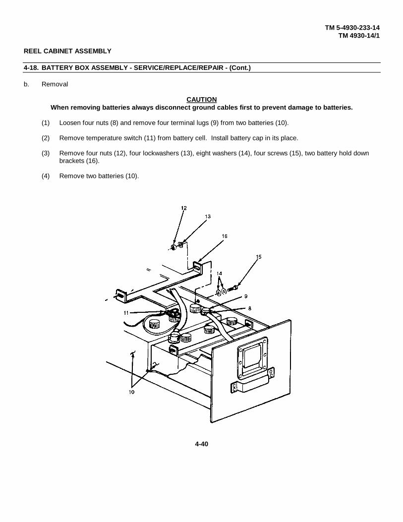
TM 5-4930-233-14TM 4930-14/1
REEL CABINET ASSEMBLY
4-18. BATTERY BOX ASSEMBLY - SERVICE/REPLACE/REPAIR - (Cont.)
b. Removal
CAUTIONWhen removing batteries always disconnect ground cables first to prevent damage to batteries.
(1) Loosen four nuts (8) and remove four terminal lugs (9) from two batteries (10).
(2) Remove temperature switch (11) from battery cell. Install battery cap in its place.
(3) Remove four nuts (12), four lockwashers (13), eight washers (14), four screws (15), two battery hold down brackets (16).
(4) Remove two batteries (10).
4-40

TM 5-4930-233-14TM 4930-14/1
REEL CABINET ASSEMBLY
4-18. BATTERY BOX ASSEMBLY - SERVICE/REPLACE/REPAIR - (Cont.)
(5) Remove nut (17), lockwasher (18), two flatwashers (21), screw (19) to disconnect ground lead (20). Reinstallscrew, lockwasher and nut.
(6) Remove battery temperature sending unit by removing grommet from reel cabinet (para 4-17).
(7) Remove nut (22) and starter lead (23).
4-41
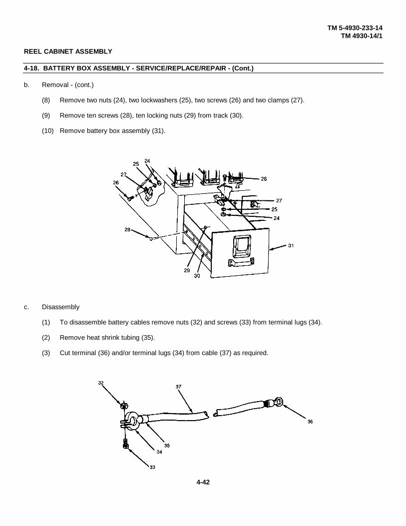
TM 5-4930-233-14TM 4930-14/1
REEL CABINET ASSEMBLY
4-18. BATTERY BOX ASSEMBLY - SERVICE/REPLACE/REPAIR - (Cont.)
b. Removal - (cont.)
(8) Remove two nuts (24), two lockwashers (25), two screws (26) and two clamps (27).
(9) Remove ten screws (28), ten locking nuts (29) from track (30).
(10) Remove battery box assembly (31).
c. Disassembly
(1) To disassemble battery cables remove nuts (32) and screws (33) from terminal lugs (34).
(2) Remove heat shrink tubing (35).
(3) Cut terminal (36) and/or terminal lugs (34) from cable (37) as required.
4-42

TM 5-4930-233-14TM 4930-14/1
REEL CABINET ASSEMBLY
4-18. BATTERY BOX ASSEMBLY - SERVICE/REPLACE/REPAIR - (Cont.)
d. Repair
CAUTION
Do not allow baking soda solution to enter batteries. Failure to do so could damage equipment.
(1) Flush metallic parts and battery cable ends with a solution of baking soda and water, to neutralize any acid on these parts.
(2) Clean battery tops with a baking soda and water solution. Do not allow mixture to enter batteries.
WARNING
Clean all parts in a well ventilated area. Avoid inhalation of solvent fumes andprolonged exposure of the skin to the cleaning solvent. Failure to do so cancause severe injury or death. Do not use near flame or excessive heat. Flashpoint of solvent is 100°F to 138°F (38°C to 59°C).
(3) Remove any grease or gummy deposits with dry cleaning solvent.
(4) Inspect batteries for cracks, loose posts or other damage. Replace if needed.
(5) Inspect battery cables for corrosion, breaks or deteriorated insulation. Replace if damaged.
(6) Inspect all sheet metal parts for cracked or broken weldments, dents or distortion. Re-weld and straighten parts as necessary.
(7) Inspect all parts for obvious wear or damage. Replace as required.
4-43

TM 5-4930-233-14TM 4930-14/1
REEL CABINET ASSEMBLY
4-18. BATTERY BOX ASSEMBLY - SERVICE/REPLACE/REPAIR - (Cont.)
e. Assembly
(1) Strip battery cable insulation to terminal well depth as required.
(2) Slide length of heat shrink tubing (35) onto battery cable (37) as follows.
a Black tubing for negative battery cable and jumper cable
b Red tubing for positive battery cable.
(3) Install terminal lugs (34) and/or terminal (36) onto cable (37). Crimp ends securely.
(4) Move heat shrink tubing (35) over exposed wire and shrink by applying heat.
(5) Install screws (33) and nuts (32) onto terminal lugs (34).
4-44

TM 5-4930-233-14TM 4930-14/1
REEL CABINET ASSEMBLY
4-18. BATTERY BOX ASSEMBLY - SERVICE/REPLACE/REPAIR - (Cont.)
f. Installation
(1) Install battery box assembly (31).
(2) Install track (30), ten screws (28) and ten self locking nuts (29).
(3) Install two clamps (27), two screws (26), two lockwashers (25) and two nuts (24).
(4) Lubricate drawer rail (para 3-2) to insure smooth operation.
4-45
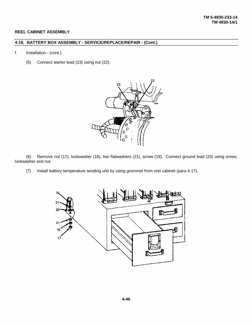
TM 5-4930-233-14TM 4930-14/1
REEL CABINET ASSEMBLY
4-18. BATTERY BOX ASSEMBLY - SERVICE/REPLACE/REPAIR - (Cont.)
f. Installation - (cont.)
(5) Connect starter lead (23) using nut (22).
(6) Remove nut (17), lockwasher (18), two flatwashers (21), screw (19). Connect ground lead (20) using screw,lockwasher and nut.
(7) Install battery temperature sending unit by using grommet from reel cabinet (para 4-17).
4-46

TM 5-4930-233-14TM 4930-14/1
REEL CABINET ASSEMBLY
4-18. BATTERY BOX ASSEMBLY - SERVICE/REPLACE/REPAIR - (Cont.)
(8) Install two batteries (10).
(9) Install two battery hold down brackets (16) using six screws (15), 12 washers (14), six lockwashers (13) and six nuts (12).
(10) Remove temporary cap from battery cell and install temperature switch (11).
(11) Loosen four nuts (8) and install four terminal lugs (9) on two batteries (10). Tighten nuts (8).
(12) Coat battery terminal with grease.
4-47

TM 5-4930-233-14TM 4930-14/1
REEL CABINET ASSEMBLY
4-19. GEAR LUBE AND ENGINE OIL DISPENSERS - REPLACEThis task covers:
a. Removal b. Installation
INITIAL SET-UP:
ToolsGeneral Mechanics Tool Box(Section III, Item 1, AppB)
a. Removal
(1) Vent lube pressure completely by opening valve (1). Close valve (1).
(2) Loosen swivel (2) and remove gear lube dispenser (3).
(3) Loosen swivel (4) and remove engine oil dispenser (5).
(4) Loosen two nuts (6) and remove two grease control valves (7).
b. Installation
(1) Install two grease control valves (7) and tighten two nuts (6).
(2) Install engine oil dispenser (5) and tighten swivel (4).
(3) Install gear lube dispenser (3) and tighten swivel (2).
4-48

TM 4930-14/1
4-49
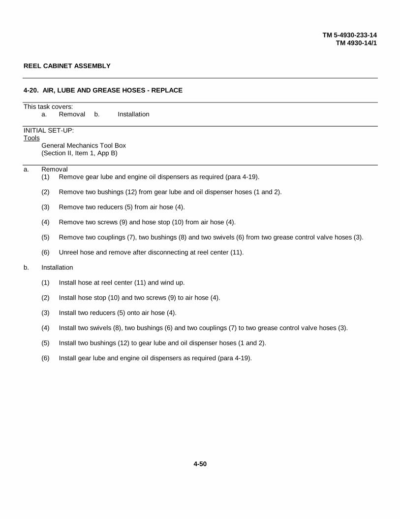
TM 5-4930-233-14TM 4930-14/1
REEL CABINET ASSEMBLY
4-20. AIR, LUBE AND GREASE HOSES - REPLACE
This task covers:a. Removal b. Installation
INITIAL SET-UP:Tools
General Mechanics Tool Box(Section II, Item 1, App B)
a. Removal(1) Remove gear lube and engine oil dispensers as required (para 4-19).
(2) Remove two bushings (12) from gear lube and oil dispenser hoses (1 and 2).
(3) Remove two reducers (5) from air hose (4).
(4) Remove two screws (9) and hose stop (10) from air hose (4).
(5) Remove two couplings (7), two bushings (8) and two swivels (6) from two grease control valve hoses (3).
(6) Unreel hose and remove after disconnecting at reel center (11).
b. Installation
(1) Install hose at reel center (11) and wind up.
(2) Install hose stop (10) and two screws (9) to air hose (4).
(3) Install two reducers (5) onto air hose (4).
(4) Install two swivels (8), two bushings (6) and two couplings (7) to two grease control valve hoses (3).
(5) Install two bushings (12) to gear lube and oil dispenser hoses (1 and 2).
(6) Install gear lube and engine oil dispensers as required (para 4-19).
4-50
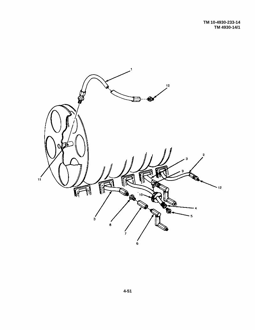
TM 10-4930-233-14TM 4930-14/1
4-51

TM 10-4930-233-14TM 4930-14/1
REEL CABINET ASSEMBLY
4-20.1. AIR, LUBE AND GREASE HOSES - REPAIR
This task covers:
a. Disassembly b. Repair c. Assembly
INITIAL SET-UP:
Equipment Condition NOTEAir, lube or grease hoses The following procedure applies to anyremoved (para. 4-20) of five air, lube, and grease hoses.
ToolsGeneral Mechanics Tool Box(Section III, Item 1, App B)
a. Disassembly
Remove two reusable fittings (1) from hose (2).
b. Repair
(1) Inspect hose for deterioration or wear. Replace hose if required.
(2) If hose has a break or cut near either end, cut damage off of hose and reuse.
(3) Inspect fittings for damage. Replace if defective.
c. Assembly
Install two fittings (1) onto hose (2).
Change 1 4-52
TM 10-4930-233-14TM 4930-14/1
REEL CABINET ASSEMBLY
4-21. REEL ASSEMBLY - REPLACE/REPAIR
This task covers:
a. Removal b. Disassembly c. Repair d. Assembly e. Installation
INITIAL SET-UP:
Tools Materials/PartsGeneral Mechanics Tool Box Teflon Tape (Item 18, App E)(Section III, Item 1, App B)
Equipment ConditionGear lube and engine oil dispensersremoved (para 4-19)Air, lube and grease hosesremoved (para 4-20)
WARNINGRelease pressure from hoses by activating dispensing handle and disconnect line slowly;otherwise pressure in line may result in injury.
a. Removal
(1) Remove elbows (2) from reel.
(2) Disconnect lube and air hose (1) from elbows (2).
(3) Remove 4 screws (3), 4 lockwashers (4), 4 flatwashers (5) and reel assembly (6).
(4-52.1 blank)/4-52.2 Change 1

TM 10-4930-233-14TM 4930-14/1
REEL CABINET ASSEMBLY
4-21. REEL ASSEMBLY - REPLACE/REPAIR - (Cont.)
b. DisassemblyNOTE
The following applies to any of the five reel assemblies.
(1) Remove cotter pin (7) and hose reel (8).
(2) Remove four self-locking nuts (9), four screws (10) and roller assembly (11).
(3) To disassemble roller assembly (11) remove four shafts (12), four rollers (13) from roller mount (14).
(4) Remove two self-locking nuts (15), four washers (16), two screws (17) and roller bracket (18) from reelbracket (19).
4-53

TM 10-4930-233-14TM 4930-14/1
REEL CABINET ASSEMBLY
4-21. REEL ASSEMBLY - REPLACE/REPAIR
c. Repair
(1) Replace six self-locking nuts (9 and 15) and cotter pin (7).
(2) Inspect all other parts for damaged threads, cracks, distortion and other damage. Replace parts as needed.
Change 1 4-54
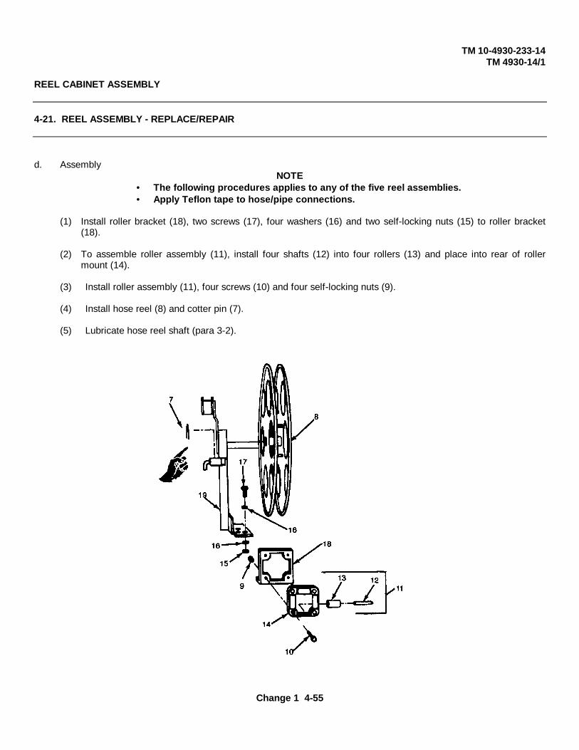
TM 10-4930-233-14TM 4930-14/1
REEL CABINET ASSEMBLY
4-21. REEL ASSEMBLY - REPLACE/REPAIR
d. AssemblyNOTE
• The following procedures applies to any of the five reel assemblies.• Apply Teflon tape to hose/pipe connections.
(1) Install roller bracket (18), two screws (17), four washers (16) and two self-locking nuts (15) to roller bracket(18).
(2) To assemble roller assembly (11), install four shafts (12) into four rollers (13) and place into rear of rollermount (14).
(3) Install roller assembly (11), four screws (10) and four self-locking nuts (9).
(4) Install hose reel (8) and cotter pin (7).
(5) Lubricate hose reel shaft (para 3-2).
Change 1 4-55
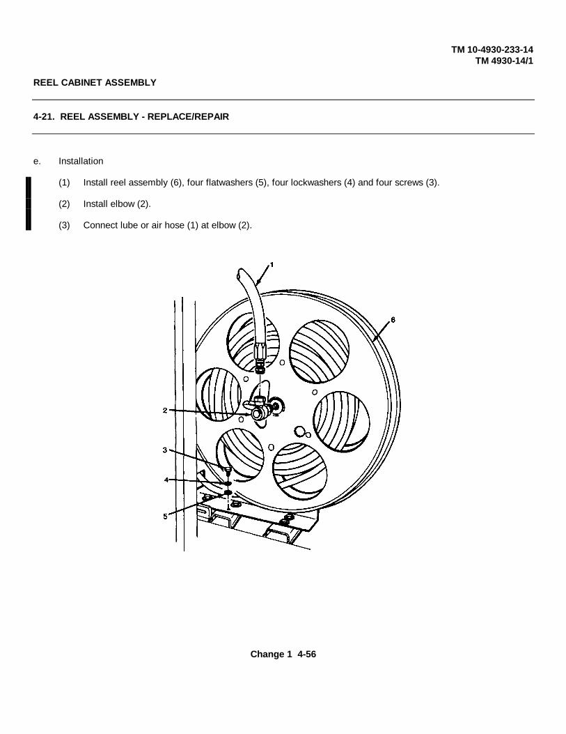
TM 10-4930-233-14TM 4930-14/1
REEL CABINET ASSEMBLY
4-21. REEL ASSEMBLY - REPLACE/REPAIR
e. Installation
(1) Install reel assembly (6), four flatwashers (5), four lockwashers (4) and four screws (3).
(2) Install elbow (2).
(3) Connect lube or air hose (1) at elbow (2).
Change 1 4-56
TM 10-4930-233-14TM 4930-14/1
AIR COMPRESSOR ASSEMBLY
4-22. BELTS - REPLACE/ADJUST
This task covers:a. Removal b. Installation c. Adjustment
INITIAL SET-UP:
Tools Equipment Condition PageGeneral Mechanics Tool Box Enclosure Removed (para 4-11)(Section III, Item 1, App B)
a. Removal
NOTEFollow step (1) through (5) for removal of compressor drive belts and guard. Proceed to step (6)for removal of alternator belt and guard.
(1) Disconnect engine exhaust tube from exhaust diverter.
(2) Remove four mounting bolts, four lockwashers and four nuts (para 4-31).
(3) Slide compressor back against tool box and fuel tank (para 4-31).
(4) Remove six screws (8) and three brackets (9) from belt guard (7).
(5) Remove two nuts (1), two lockwashers (2), two washers (3) and two screws (4).
(6) Remove screw (5), lockwasher (6) from belt guard (7).
(7) Remove two screws (13) and two flatwashers (14) from inner belt guard (15)
(8) Slide inner belt guard (15) up and remove.
(9) Move front belt guard (7) forward as much as possible.
4-57

TM 10-4930-233-14TM 4930-14/1
AIR COMPRESSOR ASSEMBLY
4-22. BELTS - REPLACE/ADJUST
a. Removal - (cont.)
(10) Loosen four compressor mounting bolts (10) and slide compressor (11) toward engine to relieve belt tension.
NOTEDrive belts must be replaced as a pair.
(11) Remove two belts (12).
4-58

TM 10-4930-233-14TM 4930-14/1
AIR COMPRESSOR ASSEMBLY
4-22. BELTS - REPLACE/ADJUST
(12) Remove screw (16), lockwasher (17), one nut (18), bolt (19), lockwasher (20), and guard (21).
Change 1 4-59

TM 10-4930-233-14TM 4930-14/1
AIR COMPRESSOR ASSEMBLY
4-22. BELTS - REPLACE/ADJUST
a. Removal - (cont.)
(13) Loosen screw (19) and nut (22) and rotate alternator (23) to relieve tension on belt (24).
(14) Remove belt (24).
b. Installation
NOTE• Follow steps (1) through (5) for installation of alternator belt and guard.• Proceed to step (6) for installation of compressor drive belts and guard.
(1) Install belt (24).
(2) Adjust belt tension (para 4-22c)
(3) Install belt guard (21), screw (16), lockwasher (17), one nut (18), bolt (19), lockwasher (20).
(4) Install two belts (12).
(5) Adjust belt tension (para 4-22c).
(6) Move front guard (7) back into place.
Change 1 4-60
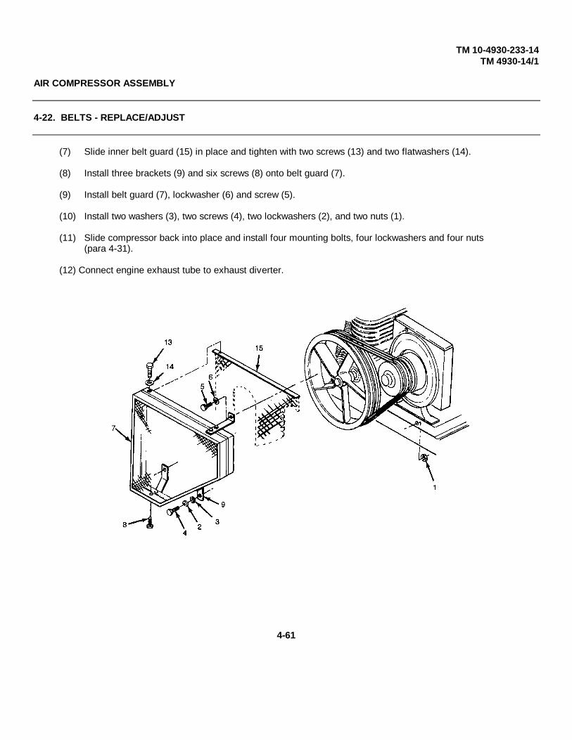
TM 10-4930-233-14TM 4930-14/1
AIR COMPRESSOR ASSEMBLY
4-22. BELTS - REPLACE/ADJUST
(7) Slide inner belt guard (15) in place and tighten with two screws (13) and two flatwashers (14).
(8) Install three brackets (9) and six screws (8) onto belt guard (7).
(9) Install belt guard (7), lockwasher (6) and screw (5).
(10) Install two washers (3), two screws (4), two lockwashers (2), and two nuts (1).
(11) Slide compressor back into place and install four mounting bolts, four lockwashers and four nuts(para 4-31).
(12) Connect engine exhaust tube to exhaust diverter.
4-61

TM 5-4930-233-14TM 4930-14/1
AIR COMPRESSOR ASSEMBLY
4-22. BELTS - REPLACE/ADJUST - (Cont.)
c. AdjustmentNOTE
• To adjust compressor drive belts, do steps (1) through (5). • To adjust alternator belt, go to step (6).
(1) Remove compressor belt guard (para 4-22a).
(2) Loosen four compressor mounting bolts (10).
(3) Slide compressor (11) toward the engine to loosen the drive belts (12) and away from the engine to tighten.When drive belts are properly adjusted, they should deflect 1/2 to 3/4 inch (12.7 to 19.05 mm) using thumbpressure at midpoint of the belt.
(4) Tighten four compressor mounting bolts (10).
(5) Install belt guard (para 4-22b).
4-62

TM 5-4930-233-14TM 4930-14/1
AIR COMPRESSOR ASSEMBLY
4-22. BELTS - REPLACE/ADJUST - (Cont.)
(6) Remove alternator drive belt guard (para 4-22a).
(7) Loosen screw (23) and (27), and nut (24) and (28).
(8) To adjust belt (26) tension move the position of the alternator (25) until the belt deflects 1/2 in. (12.7 mm)when thumb pressure is applied at midpoint between the pulleys.
(9) Tighten nut (24) and (28), and screw (23) and (27).
(10) Install alternator drive belt guard (para 4-21b).
4-63
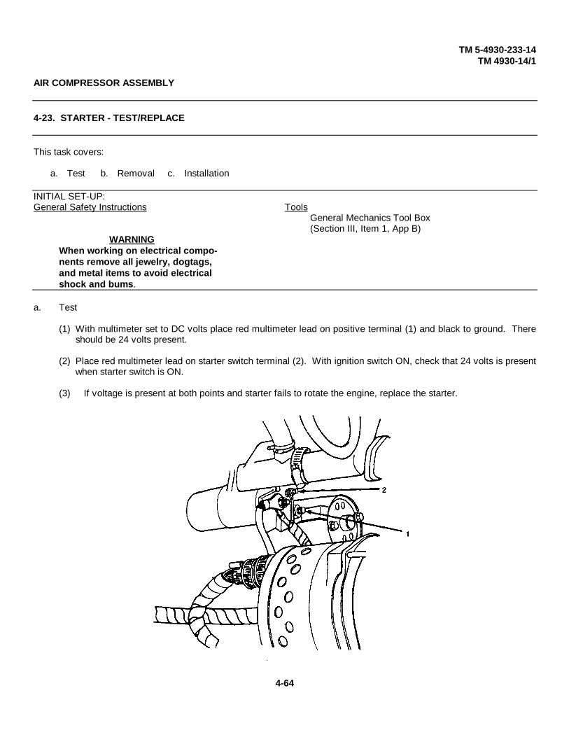
TM 5-4930-233-14TM 4930-14/1
AIR COMPRESSOR ASSEMBLY
4-23. STARTER - TEST/REPLACE
This task covers:
a. Test b. Removal c. Installation
INITIAL SET-UP:General Safety Instructions Tools
General Mechanics Tool Box(Section III, Item 1, App B)
WARNINGWhen working on electrical compo-nents remove all jewelry, dogtags,and metal items to avoid electricalshock and bums.
a. Test
(1) With multimeter set to DC volts place red multimeter lead on positive terminal (1) and black to ground. Thereshould be 24 volts present.
(2) Place red multimeter lead on starter switch terminal (2). With ignition switch ON, check that 24 volts is presentwhen starter switch is ON.
(3) If voltage is present at both points and starter fails to rotate the engine, replace the starter.
4-64

TM 5-4930-233-14TM 4930-14/1
AIR COMPRESSOR ASSEMBLY
4-23. STARTER - TEST/REPLACE - (Cont.)
b. Removal
(1) Disconnect negative battery lead.
(2) Remove alternator belt and guard and move alternator to lowest position (para 4-22a).
(3) Remove nut (3), ignition lead (4), winterization lead (5) and positive battery lead (6) from positive starterbattery terminal (1).
(4) Remove nut (7) and starter switch lead (8) from starter switch terminal (2).
(5) Remove two screws (9), two lockwashers (10) and pull starter motor (11) straight out from engine.
(6) Remove ground wire (12) and bolt (13) from starter.
c. Installation
(1) Install ground wire (12) and bolt (13) to starter.
(2) Install starter motor (11), two lockwashers (10) and two screws (9).
(3) Install starter switch lead (8) and nut (7) onto starter switch terminal (2).
(4) Install positive battery lead (6), winterization lead (5), ignition lead (4) and nut (3) onto positive starter batteryterminal (1).
(5) Install alternator belt and guard (para 4-22a).
(6) Connect negative battery lead.
4-65

TM 54930-233-14TM 4930-14/1
AIR COMPRESSOR ASSEMBLY
4-24. ALTERNATOR - TEST/REPLACE
This task covers:a. Test b. Removal c. Installation
INITIAL SET-UP:
Test Equipment General Safety InstructionsMultimeter(Section III, Item 4, App B)
Tools WARNINGGeneral Mechanics Tool Box When working on electrical compo-
nents remove all jewelry, dogtags,(Section III, Item 1, App B) and metal items to avoid electricalshock and bums.
Equipment ConditionBelts Removed (para 4-22)
a. Test
(1) Attach multimeter leads (1), positive to positive battery terminal, and negative to negative battery terminal.
(2) Check voltage. Voltage reading should be 24 volts without engine running.
(3) Start engine. Voltage reading should be 25 to 26 volts. If not 25 to 26 volts, set adjusting screw accordingly.
NOTETurn adjusting screw (2) clockwise to increase, counterclockwise to decrease.
(4) If voltage cannot be adjusted to proper level, remove alternator and replace.
4-66

TM 5-4930-233- 4TM 4930-14/1
AIR COMPRESSOR ASSEMBLY
4-24. ALTERNATOR - TEST/REPLACE - (Cont.)
b. Removal
(1) Disconnect electrical connector (3).
CAUTION
Alternator (11) must be supported while removing alternator bracket to prevent equipmentdamage.
(2) Remove screw (4), lockwasher (5), washer (6) and spacer (7).
(3) Remove nut (8), screw (9) and flatwasher (12) and lockwasher (10).
(4) Remove alternator (11).
c. Installation
(1) Install alternator (11) in place.
(2) Install lockwasher (10), flatwasher (12), screw (9) and nut (8).
(3) Install spacer (7), washer (6), lockwasher (5), and screw (4).
(4) Connect electrical connector (3).
4-67

TM 5-4930-233-14TM 4930-14/1
AIR COMPRESSOR ASSEMBLY
4-25. WIRING HARNESS - TEST/REPLACE/REPAIR
This task covers:a. Test b. Removal c. Repair d. Installation
INITIAL SET-UP:General Safety Instructions Tools
General Mechanics Tool Box
Test EquipmentWARNING Multimeter (Section III, Item 4, App B)
When working on electrical multi-meter components, remove all jew-elry, dogtags, and metal items toavoid electrical shock and bums.
a. Test
See wiring diagram and wire list (Table 4-3). Perform continuity tests on individual wires. Replace or repair wireswith no continuity.
4-68
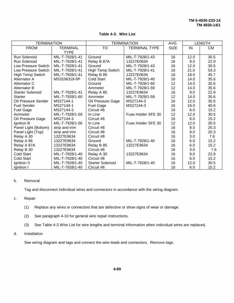
TM 5-4930-233-14TM 4930-14/1
Table 4-3. Wire List
TERMINATION TERMINATION AVG. LENGTHFROM TERMINAL
TYPETO TERMINAL TYPE SIZE IN. CM
Run Solenoid MIL-T-7928/1-41 Ground MIL-T-7928/1-43 16 12.0 30.5Run Solenoid MIL-T-7928/1-41 Relay B 87A 13227E0634 16 9.0 22.9Low Pressure Switch MIL-T-7928/1-41 Ground MIL-T-7928/1-43 16 12.0 30.5Low Pressure Switch MIL-T-7928/1-41 High Temp Switch MIL-T-7928/1-41 16 21.0 53.3High Temp Switch MIL-T-7928/1-41 Relay B 89 13227E0634 16 18.0 45.7Alternator A MS3106318-5P Cold Start MIL-T-7928/1-40 16 14.0 35.6Alternator C Ground MIL-T-7928/1-60 12 14.0 35.6Alternator B Ammeter MIL-T-7928/1-59 12 14.0 35.6Starter Solenoid MIL-T-7928/1-41 Relay A 85 13227E9634 16 9.0 22.9Starter MIL-T-7928/1-60 Ammeter MIL-T-7928/1-59 12 14.0 35.6Oil Pressure Sender MS27144-1 Oil Pressure Gage MS27144-3 16 12.0 30.5Fuel Sender MS27144-1 Fuel Gage MS27144-3 16 16.0 40.6Fuel Gage MS27144-3 Circuit #8 16 6.0 15.2Ammeter MIL-T-7928/1-59 In Line Fuse Holder SFE 30 12 12.0 30.5Oil Pressure Gage MS27144-3 Circuit #8 16 6.0 15.2Ignition B MIL-T-7928/1-56 In Line Fuse Holder SFE 30 12 12.0 30.5Panel Light (Bottom) strip and trim Circuit #8 16 8.0 20.3Panel Light (Top) strip and trim Circuit #8 16 8.0 20.3Relay A 30 13227E9634 Circuit #8 16 3.0 7.6Relay A 86 13227E9634 Ground MIL-T-7928/1-40 16 6.0 15.2Relay A 87A 13227E9634 Relay B 85 13227E9634 16 6.0 15.2Relay B 30 13227E9634 Circuit #8 16 3.0 7.6Cold Start MIL-T-7928/1-40 Relay A 30 13227E9634 16 9.0 22.9Cold Start MIL-T-7928/1-40 Circuit #8 16 6.0 15.2Ignition S MIL-T-7928/1-40 Starter Solenoid MIL-T-7928/1-40 16 12.0 30.5Ignition I MIL-T-7928/1-40 Circuit #8 16 6.0 15.2
b. Removal
Tag and disconnect individual wires and connectors in accordance with the wiring diagram.
c. Repair
(1) Replace any wires or connectors that are defective or show signs of wear or damage.
(2) See paragraph 4-10 for general wire repair instructions.
(3) See Table 4-3 Wire List for wire lengths and terminal information when individual wires are replaced.
d. Installation
See wiring diagram and tags and connect the wire leads and connectors. Remove tags.
4-69

TM 5-4930-233-14TM 4930-14/1
AIR COMPRESSOR ASSEMBLY
4-26. CONTROL PANEL- TEST/REPLACE/REPAIR
This task covers:a. Test b. Removal c. Disassembly d. Repaire. Assembly f. Installation
INITIAL SET-UP:Materials/Parts General Safety Instructions
Teflon tape (Item 18, App E)
Tools WARNINGGeneral Mechanics Tool Box When working on electrical compo-(Section III, em 1, App B) nents remove all jewelry, dogtags,
and metal items to avoid electricalTest Equipment shock and burns.
Multimeter (Section III, Item 4, App B)
NOTE
For the starter/ignition switch (2) continuity should not be present between terminals:
• B and S when switch is OFF • B and I when switch is IGN • S and I when switch is START
a. Test
(1) Tag and disconnect three electrical leads (1) from starter/ignition switch (2).
(2) With multimeter, test starter/ignition switch (2) by checking for continuity between terminals.
(3) If switch is defective, replace (para 4-26c).
(4) Tag and disconnect two electrical leads (3) from cold start switch (4).
(5) With multimeter, test cold start switch (4) for continuity between terminals.
(6) If continuity is not present, replace cold start switch (4) (para 4-26c).
(7) Tag and disconnect four electrical leads (5) from relay A (6).
(8) With multimeter, test relay A (6) for continuity between terminals 30 and 87A. If no continuity is present,replace relay A (6).
(9) Repeat test between terminals 30 and 87. If continuity is present, replace relay A (6).
4-70

TM 5-4930-233-14TM 4930-14/1
AIR COMPRESSOR ASSEMBLY
4-26. CONTROL PANEL - TEST/REPLACE/REPAIR - (Cont.)
(10) Connect 24 volt power source with jumper wires to terminals 85 and 86 of relay A (6). If no clicking sound ispresent, replace relay A (6).
(11) With jumper wires in place, test for continuity between terminals 30 and 87 of relay A (6). If no continuity ispresent, replace relay A (6)
(12) Repeat test between terminals 30 and 87A. If continuity is present, replace relay A (6) (para 4-26c).
(13) Repeat steps (7) through (12) for relay B (7)
4-71

TM 5-4930-233-14TM 4930-14/1
AIR COMPRESSOR ASSEMBLY
4-26. CONTROL PANEL- TEST/REPLACE/REPAIR - (Cont.)
b. Removal
NOTE
The control panel does not need to be removed for removal of individual gages.
(1) Tag and remove all electrical connectors in accordance with the wiring diagram.
(2) Disconnect air tube (8) from air pressure gage (9).
4-72
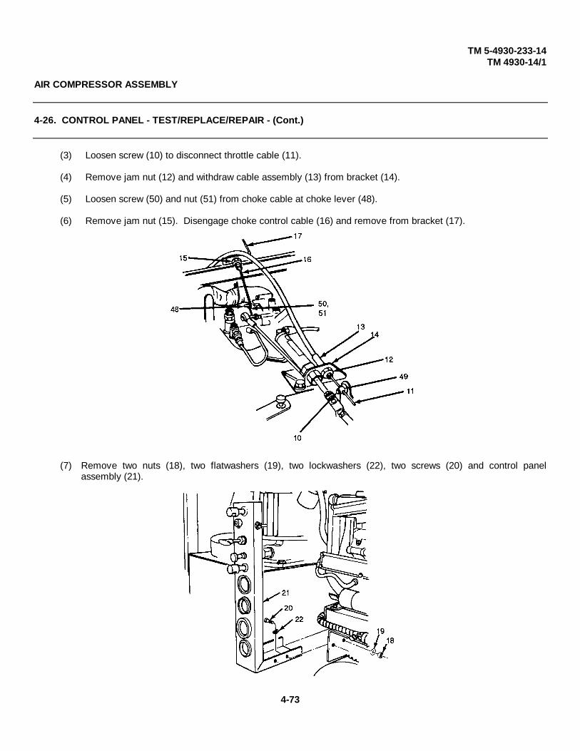
TM 5-4930-233-14TM 4930-14/1
AIR COMPRESSOR ASSEMBLY
4-26. CONTROL PANEL - TEST/REPLACE/REPAIR - (Cont.)
(3) Loosen screw (10) to disconnect throttle cable (11).
(4) Remove jam nut (12) and withdraw cable assembly (13) from bracket (14).
(5) Loosen screw (50) and nut (51) from choke cable at choke lever (48).
(6) Remove jam nut (15). Disengage choke control cable (16) and remove from bracket (17).
(7) Remove two nuts (18), two flatwashers (19), two lockwashers (22), two screws (20) and control panelassembly (21).
4-73

TM 5-4930-233-14TM 4930-14/1
AIR COMPRESSOR ASSEMBLY
4-26. CONTROL PANEL - TEST/REPLACE/REPAIR - (Cont.)
c. Disassembly(1) Remove two bulbs (22) from two dash lamps (23).
(2) Remove four nuts (24), four lockwashers (25), two ground leads (26), four screws (27), and two dash lamps(23).
(3) Remove nut (53), flatwasher (29), starwasher (52), and cold start switch (4).
(4) Remove screw (54), lockwasher (55), starwasher (58), nut (56), and starter/ignition switch (2).
(5) Remove jam nut (33), starwasher (52), and remove throttle cable assembly (13).
(6) Remove knob (32), jam nut (31), starwasher (52), and choke cable (16).
(7) Remove two nuts (34), bracket (35), and air pressure gage (9).
(8) Remove two nuts (36), two lockwashers (37), mounting clamp (38), and oil pressure gage (39).
(9) Remove three screws (40), three lockwashers (59), three nuts (60), and ammeter (41).
(10) Remove two nuts (42), two lockwashers (43), mounting clamp (44), and fuel gage (45).
(11) Drill out rivets and remove two relays (51).
(12) Remove control panel plate (46) from control panel (47).
d. Repair
(1) Inspect gages for discolored or illegible markings, bent or sticking dial pointers and loose, damaged orcorroded connectors. Replace defective gages.
(2) Check operation of switches. The toggle switch must operate positively to each of its positions. If the switchis suspect, test (para 4-26a).
(3) Inspect all electrical connections. Replace components that have loose, corroded or damaged connectors.
(4) Check operation of choke control and throttle cables. If necessary, lubricate with light oil. If sheathes arekinked or broken or if the cables stick or bind, replace the controls.
(5) Inspect control panel find plate for cracks, illegible markings and damage. Replace if necessary.
4-74

TM 5-4930-233-14TM 4930-14/1
AIR COMPRESSOR ASSEMBLY
4-26. CONTROL PANEL - TEST/REPLACE/REPAIR - (Cont.)
e. Assembly
(1) Place control panel plate (46) onto control panel (47).
(2) Install two relays (51) using rivets as necessary.
(3) Install fuel gage (45), mounting clamp (44), two lockwashers (43) and two nuts (42).
(4) Install ammeter (41), three lockwashers (59), three nuts (60) and three screws (40).
(5) Install oil pressure gage (39), mounting clamp (38), two lockwashers (37) and two nuts (36).
(6) Install air pressure gage (9), bracket (35) and two nuts (34).
(7) Install choke cable (16), jam nut (31), starwasher (52), and knob (32).
(8) Install throttle cable assembly (13), starwasher (52) and jam nut (33).
4-75

TM 5-4930-233-14TM 4930-14/1
AIR COMPRESSOR ASSEMBLY
4-26. CONTROL PANEL - TEST/REPLACE/REPAIR - (Cont.)
e. Assembly - (cont.)
(9) Install starter/ignition switch (2), screw (54), lockwasher (55), starwasher (58) and nut (56).
(10) Install cold start switch (4), nut (53), flatwasher (29) and starwasher (52).
(11) Install dash lamps (23), four screws (27), two ground leads (26), four lockwashers (25) and four nuts (24).
(12) Install two bulbs (22) into two dash lamps (23).
f. Installation
(1) Install control panel assembly (21) using two screws (20) four washers (19) and two nuts(18).
4-76

TM 5-4930-233-14TM 4930-14/1
AIR COMPRESSOR ASSEMBLY
4-26. CONTROL PANEL - TEST/REPLACE/REPAIR - (Cont.)
NOTE
When using choke control and throttle cables, be sure to adjust positions to allow full range ofmovement of the choke lever or throttle lever.
(2) Slide choke control cable assembly (16) through bracket (17).
(3) Install jam nut (15).
(4) Engage choke control (16) at choke lever (48). Install screw (51) and nut (50) to choke cable.
(5) Slide throttle control assembly (13) through bracket (14) and install jam nut (12).
(6) Slide throttle cable (11) through throttle lever (49) and tighten screw (10).
(7) Tape threads and install air tube (8) to pressure gage (9).
(8) Install all electrical connectors in accordance with the wiring diagram and tags. Remove tags.
4-77

TM 5-4930-233-14TM 4930-1411
AIR COMPRESSOR ASSEMBLY
4-27. PILOT VALVE - ADJUST/REPLACE
This task covers:a. Adjustment b. Removal c. Installation
INITIAL SET-UP:Materials/Parts Tools
Teflon tape General Mechanics Tool Box(Item 18, App E) (Section III, Item 1, App B)
a. Adjustment
(1) To raise or lower the pressure range without increasing or decreasing the spread of the range, loosen theoutside lock nut (1), and turn the adjusting screw (2). If you turn the adjusting screw clockwise, you willincrease the pressure. Turning it counterclockwise will decrease the pressure.
(2) To adjust the spread of the range (that is, to increase or decrease the difference between the cut-in and cut-out pressure), you should loosen the inner lock nut (3) and rotate the adjusting barrel (4). Turning the barrelclockwise will increase the spread between cut-in and cut-out pressures. Turning it counterclockwise willdecrease the spread.
CAUTION
Do not leave the adjusting barrel (4) screwed down to the bottom position. It will prevent the pilotvalve from controlling
(3) If the overall range is too high or too low after adjusting the spread of the range, you must readjust theadjusting screw (2) as required. Tighten all lock nuts after making the adjustments.
(4) Replace the pilot valve if you cannot adjust it to control the pressure properly.
4-78
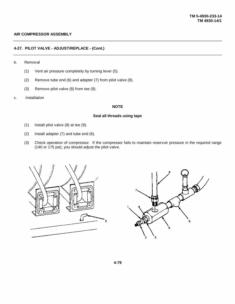
TM 5-4930-233-14TM 4930-14/1
AIR COMPRESSOR ASSEMBLY
4-27. PILOT VALVE - ADJUST/REPLACE - (Cont.)
b. Removal
(1) Vent air pressure completely by turning lever (5).
(2) Remove tube end (6) and adapter (7) from pilot valve (8).
(3) Remove pilot valve (8) from tee (9).
c. Installation
NOTE
Seal all threads using tape
(1) Install pilot valve (8) at tee (9).
(2) Install adapter (7) and tube end (6).
(3) Check operation of compressor. If the compressor fails to maintain reservoir pressure in the required range(140 or 175 psi), you should adjust the pilot valve.
4-79

TM 5-4930-233-14TM 4930-14/1
AIR COMPRESSOR ASSEMBLY
4-28. PRESSURE RELIEF VALVE - REPLACE
This task covers:a. Removal b. Installation
INITIAL SET-UP:Materials/Parts Tools
Teflon tape (Item 18, AppE) General Mechanics Tool Box(Section III, Item 1, AppB)
a. Removal
(1) Vent air pressure completely by turning lever (1).
(2) Remove pressure relief valve (2) from tee (3).
NOTESeal all thread using tape.
b. Installation
Install pressure relief valve (2) at tee (3).
4-80

TM 5-4930-233-14TM 4930-14/1
AIR COMPRESSOR ASSEMBLY
4-29. AIR COMPRESSOR - REPLACE
This task covers:a. Removal b. Installation
INITIAL SET-UP:
Personnel Materials/Parts2 Teflon Tape (Item 18, App E)
Equipment Condition ToolsEnclosure Removed (para 4-11) General Mechanics Tool BoxCompressor Drive Belts and Guard (Section III, Item 1, App B)Removed (para 4-22)Heater Removed (para 4-39)Air Compressor Hose, Lines and Fittings- Replace (para 4-32)
a. Removal
(1) Vent air pressure completely by turning lever (1).
(2) Drain compressor crankcase oil into suitable container by removing plug (7). Reinstall plug.
4-81

TM 5-4930-233-14TM 4930-14/1
AIR COMPRESSOR ASSEMBLY
4-29. AIR COMPRESSOR - REPLACE - (Cont.)
a. Removal - (cont.)
(3) Disconnect tube (8) at tee (9).
(4) Disconnect tube (10) at elbow (11). Remove elbow (11).
(5) Remove four nuts (12), four lockwashers (13), eight washers (14) and four screws (15).
(6) Disconnect winterization duct hose (17).
(7) Lift compressor (18) and remove.
(8) Remove nut (2), lockwasher (3), screw (4), flywheel (5), and key (6).
4-82
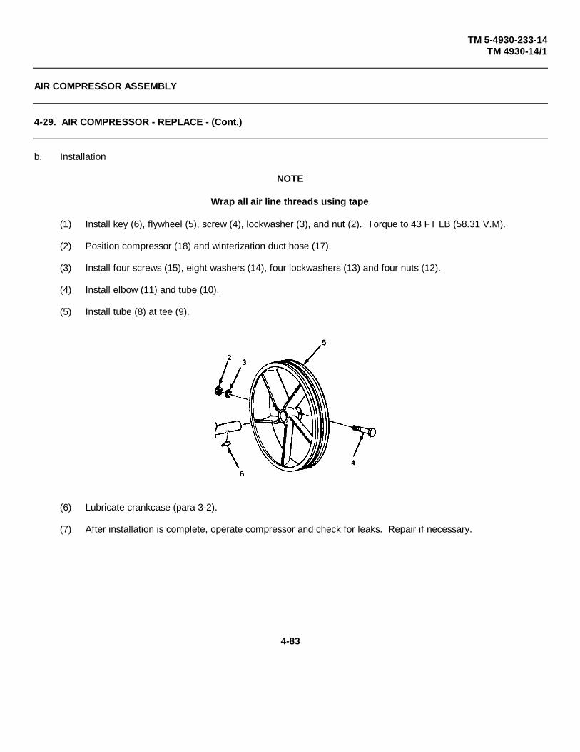
TM 5-4930-233-14TM 4930-14/1
AIR COMPRESSOR ASSEMBLY
4-29. AIR COMPRESSOR - REPLACE - (Cont.)
b. Installation
NOTE
Wrap all air line threads using tape
(1) Install key (6), flywheel (5), screw (4), lockwasher (3), and nut (2). Torque to 43 FT LB (58.31 V.M).
(2) Position compressor (18) and winterization duct hose (17).
(3) Install four screws (15), eight washers (14), four lockwashers (13) and four nuts (12).
(4) Install elbow (11) and tube (10).
(5) Install tube (8) at tee (9).
(6) Lubricate crankcase (para 3-2).
(7) After installation is complete, operate compressor and check for leaks. Repair if necessary.
4-83

TM 5-4930-233-14TM 4930-14/1
AIR COMPRESSOR ASSEMBLY
4-30. ENGINE - REPLACE
This task covers:a. Removal b. Installation
INITIAL SET-UP:
Tools Materials/Parts General Safety InstructionsGeneral Mechanics Teflon TapeTool Box(Section IlI, item 1, App B)Hoist
(Item 18, App E)Wire Connector(Item 26, App E)
When working on electrical compo-nents remove all jewelry, dogtags,and metal items to avoid electricalshock and burns.
Equipment Condition Personnel RequiredEnclosure Removed (para 4-11) 2Starter Removed (para 4-23)Alternator Removed (para 4-24)Compressor Drive Belts and Guard Removed (para 4-22)Engine Oil Extension Assembly Removed (para 4-33)
a. Removal
NOTENegative battery cable has black heat shrink tubing.
(1) Disconnect negative battery cable to engine.(2) Shut off fuel by turning valve (1).(3) Disconnect fuel line (2) at engine.
4-84
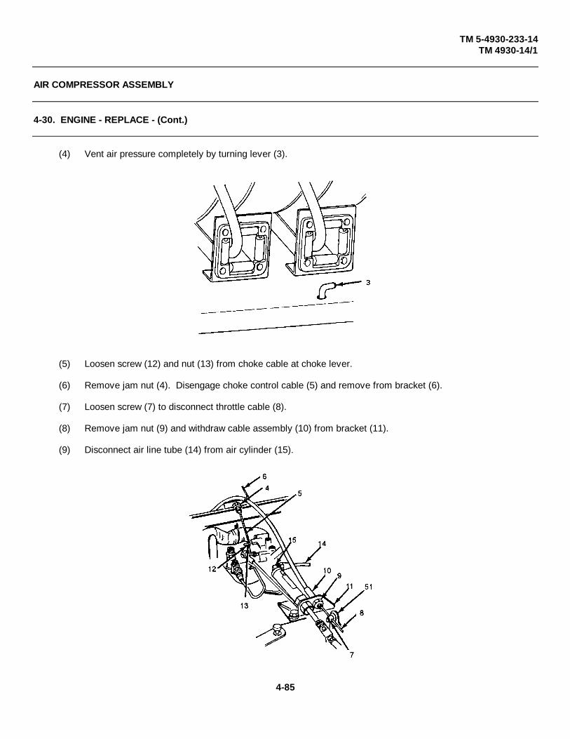
TM 5-4930-233-14TM 4930-14/1
AIR COMPRESSOR ASSEMBLY
4-30. ENGINE - REPLACE - (Cont.)
(4) Vent air pressure completely by turning lever (3).
(5) Loosen screw (12) and nut (13) from choke cable at choke lever.
(6) Remove jam nut (4). Disengage choke control cable (5) and remove from bracket (6).
(7) Loosen screw (7) to disconnect throttle cable (8).
(8) Remove jam nut (9) and withdraw cable assembly (10) from bracket (11).
(9) Disconnect air line tube (14) from air cylinder (15).
4-85
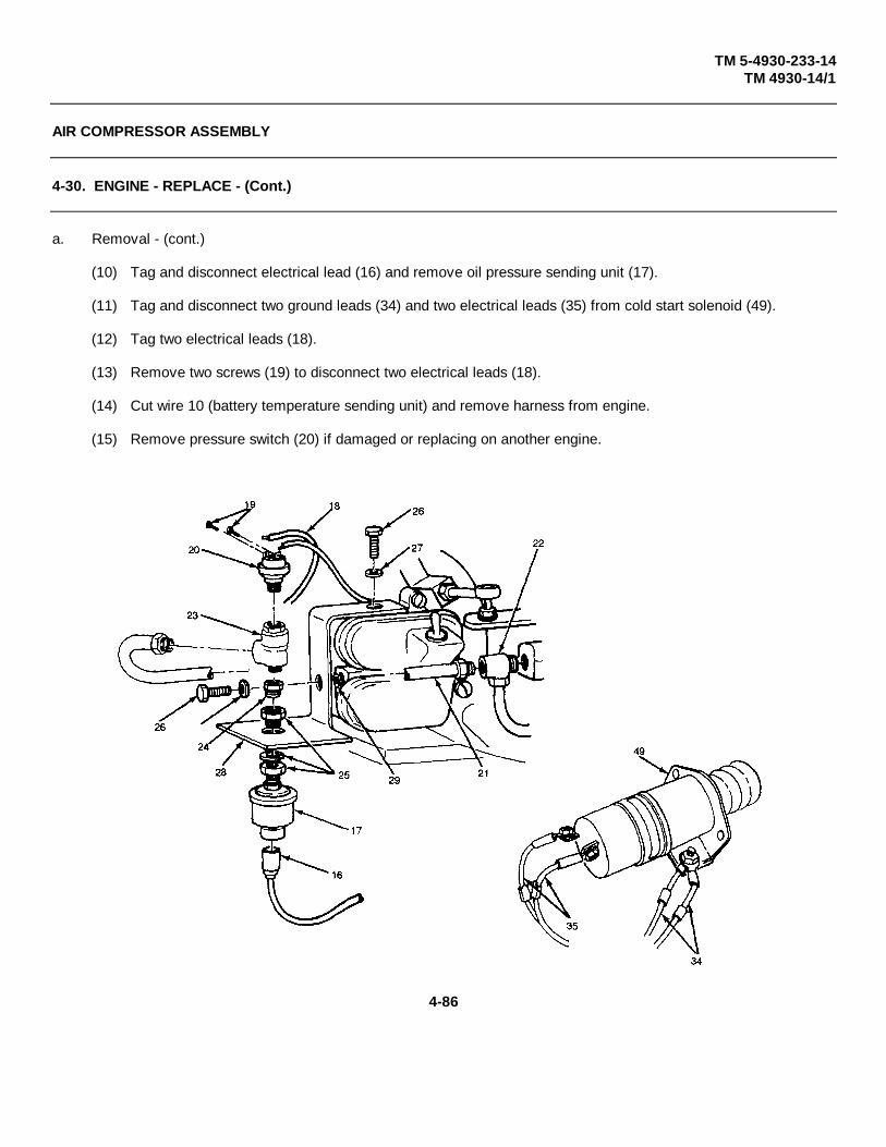
TM 5-4930-233-14TM 4930-14/1
AIR COMPRESSOR ASSEMBLY
4-30. ENGINE - REPLACE - (Cont.)
a. Removal - (cont.)
(10) Tag and disconnect electrical lead (16) and remove oil pressure sending unit (17).
(11) Tag and disconnect two ground leads (34) and two electrical leads (35) from cold start solenoid (49).
(12) Tag two electrical leads (18).
(13) Remove two screws (19) to disconnect two electrical leads (18).
(14) Cut wire 10 (battery temperature sending unit) and remove harness from engine.
(15) Remove pressure switch (20) if damaged or replacing on another engine.
4-86

TM 5-4930-233-14TM 4930-14/1
AIR COMPRESSOR ASSEMBLY
4-30. ENGINE - REPLACE - (Cont.)
(16) Remove tube assembly (21), tee (22), tee (23), bushing (24), and anchor connector (25) if damaged orreplacing on another engine.
(17) Remove two screws (26), two clockwashers (27), bracket (28), spacer (29), and ground lead (18).
(18) Tag and disconnect electrical lead (30) by removing screw (31).
(19). Remove temperature switch (32) and bushing (33) if damaged or replacing on another engine.
4-87

TM 5-4930-233-14TM 4930-14/1
AIR COMPRESSOR ASSEMBLY
4-30. ENGINE - REPLACE - (Cont.)
a. Removal - (cont.)
(20) Remove four screws (36) to disconnect two exhaust adaptors (37).
(21) Remove four nuts (45), four lockwashers (46), eight flatwashers (47) and four screws (48).
(22) Lift off engine (44) and set on blocks.
(23) Loosen setscrew (38) and remove clutch assembly (39) and key (40).
(24) Remove four screws (41), four lockwashers (42) and adapter shaft (43).
b. Installation
(1) Install adapter shaft (43), four lockwashers (42) and four screws (41).
(2) Install key (40) and clutch assembly (39). Tighten setscrew (38).
(3) Position engine (44) and install using four screws (48), eight flatwashers (47), four lockwashers (46) and fournuts (45).
(4) Connect two exhaust adapters (37) using four screws (36).
4-88

TM 5-4930-233-14TM 4930-14/1
AIR COMPRESSOR ASSEMBLY
4-30. ENGINE - REPLACE - (Cont.)
(5) Install bushing (33) and temperature switch (32) if removed.
(6) Connect electrical lead (30) using screw (31). Remove tag.
(7) Reroute wiring harness into engine and install ground lead (18). Install two ground leads (34) and twoelectrical leads (35) to cold start solenoid (49).
(8) Install spacer (29), bracket (28), two lockwashers (27) and two screws (26).
(9) Install anchor connector (25), bushing (24), tee (23), tee (22), and tube assembly (21), if removed.
(10) Install pressure switch (20) and connect two electrical leads (18) using two screws (19). Remove tags.
(11) Reconnect wire 10 to wire going to battery temperature sending unit with connector (50).
4-89

TM 5-4930-233-14TM 4930-14/1
AIR COMPRESSOR ASSEMBLY
4-30. ENGINE - REPLACE - (Cont.)
b. Installation - (cont.)
(12) Install pressure sending unit (17), if removed, and connect electrical lead (16). Remove tag.
(13) Install air line tube to air cylinder (14).
(14) Install cable assembly (10) in bracket (11) using jam nut (9).
NOTEWhen installing choke control and throttle cables, be sure to adjust positions to allow full range ofmovement of the choke lever or throttle lever.
(15) Slide throttle cable (8) through throttle lever (51) and tighten screw (7).
(16) Slide choke control cable (5) through bracket (6) and install jam nut (4).
4-90

TM 5-4930-233-14TM 4930-14/1
AIR COMPRESSOR ASSEMBLY
4-30. ENGINE - REPLACE - (Cont.)
b. Installation - (cont.)
(17) Tighten screw (12) and nut (13) to choke cable at choke lever.
(18) Engage choke control cable (5) at choke lever.
(19) Connect fuel line (2).
(20) Open shutoff valve (1).
(21) Connect negative battery cable.
4-91

TM 5-4930-233-14TM 4930-14/1
AIR COMPRESSOR ASSEMBLY
4-31. AIR RECEIVER TANK - REPLACE
This task covers:a. Removal b. Installation
INITIAL SET-UP:
Personnel Required Materials/Parts2 Teflon Tape (Item 18, App E)
Equipment Condition ToolsEnclosure removed (para 4-11) General Mechanics Tool BoxWiring Harness removed (para 4-25) (Section III, Item 1, App B)Control Panel removed (para 4-26)Air Compressor removed (para 4-29)Engine removed (para 4-30)
a. Removal
(1) Disconnect hose assembly (3) at elbow (4).
(2) Remove four nuts (18), four lockwashers (19), and four screws (20).
(3) Lift air receiver tank (21) away from skid.
(4) Remove elbow (4), hose barb (6) and bushing (5).
(5) Remove elbow (1) and check valve (2).
(6) Remove elbow (7) and hose barb (6).
(7) Remove tubes (8 and 9) and tee (10) as a unit.
(8) Remove tube (11).
(9) Remove adapter (12), pressure relief valve (13), two tees (14), pilot valve (15) and adapter (16) as a unit.
(10) Remove two plugs (17).
4-92
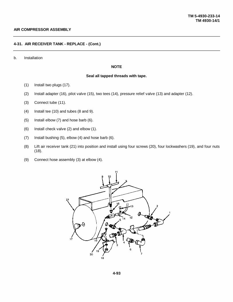
TM 5-4930-233-14TM 4930-14/1
AIR COMPRESSOR ASSEMBLY
4-31. AIR RECEIVER TANK - REPLACE - (Cont.)
b. Installation
NOTE
Seal all tapped threads with tape.
(1) Install two plugs (17).
(2) Install adapter (16), pilot valve (15), two tees (14), pressure relief valve (13) and adapter (12).
(3) Connect tube (11).
(4) Install tee (10) and tubes (8 and 9).
(5) Install elbow (7) and hose barb (6).
(6) Install check valve (2) and elbow (1).
(7) Install bushing (5), elbow (4) and hose barb (6).
(8) Lift air receiver tank (21) into position and install using four screws (20), four lockwashers (19), and four nuts(18).
(9) Connect hose assembly (3) at elbow (4).
4-93
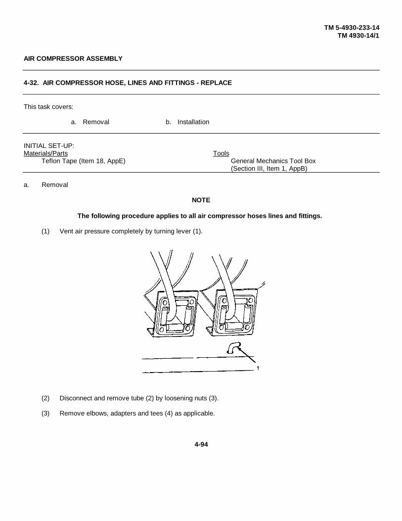
TM 5-4930-233-14TM 4930-14/1
AIR COMPRESSOR ASSEMBLY
4-32. AIR COMPRESSOR HOSE, LINES AND FITTINGS - REPLACE
This task covers:
a. Removal b. Installation
INITIAL SET-UP:Materials/Parts Tools
Teflon Tape (Item 18, AppE) General Mechanics Tool Box(Section III, Item 1, AppB)
a. Removal
NOTE
The following procedure applies to all air compressor hoses lines and fittings.
(1) Vent air pressure completely by turning lever (1).
(2) Disconnect and remove tube (2) by loosening nuts (3).
(3) Remove elbows, adapters and tees (4) as applicable.
4-94

TM 5-4930-233-14TM 4930-14/1
4-95

TM 5-4930-233-14TM 4930-14/1
AIR COMPRESSOR ASSEMBLY
4-32. AIR COMPRESSOR HOSE, LINES AND FITTINGS - REPLACE. (Cont.)
b. Installation
(1) Wrap all threads using tape
(2) Install tees, adapters and elbows (4).
(3) Install tube (2) and tighten nuts (3).
4-96

TM 5-4930-233-14TM 4930-14/1
AIR COMPRESSOR ASSEMBLY
4-33. ENGINE OIL EXTENSION ASSEMBLY - REPLACE
This task coversa. Removal b. Installation
INITIAL SET-UP:Tools
General Mechanics Tool Box(Section III, Item 1, AppB)
a. Removal
(1) Loosen clamp (1) and disconnect hose (2) at duct (3).
(2) Remove two screws (4), two lockwashers (5) and duct (3).
(3) Remove cap (7) and drain engine oil into suitable container.
(4) Remove two nuts (8), two lockwashers (9) and clamp (10).
(5) Unscrew and remove engine oil extension (11) and preformed packing (12). Discard packing.
b. Installation
(1) Install preformed packing (12) and engine oil extension (11).
(2) Install clamp (10), two lockwashers (9) and two nuts (8).
(3) Install cap (7) and fill engine crankcase with oil (para 3-2).
(4) Install grommet (6), duct (3), two lockwashers (5) and two screws (4).
(5) Install hose (2) and tighten clamp (1).
4-97

TM 5-4930-233-14TM 4930-14/1
AIR COMPRESSOR ASSEMBLY
4-34. ENGINE EXHAUST SYSTEM - REPLACE
This task covers:
a. Removal b. Installation
INITIAL SET-UP:
Equipment Condition ToolsEnclosure Removed (para 4-11) General Mechanics Tool Box
(Section III, Item 1, App B)
a. Removal
NOTE
Steps (1) through (3) apply to any of four exhaust hoses.
(1) Remove four nuts (1), four lockwashers (2) and two damps (3).
(2) Remove exhaust hoses (4).
(3) Side insulation jacket (5) off of exhaust hose.
(4) Remove four nuts (6) four screws (7) four lockwashers (8) and two exhaust adapters (9).
(5) Drill out four rivets (10) and remove exhaust diverter (11).
4-98
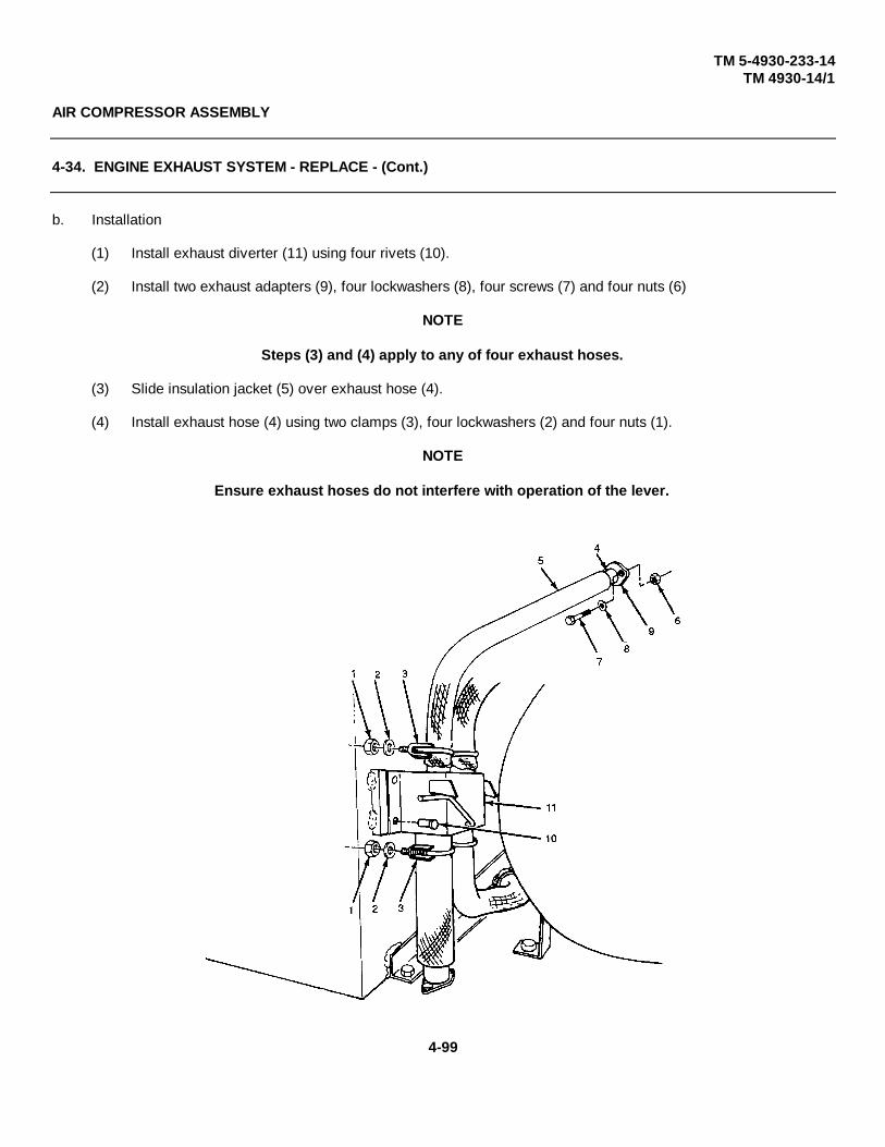
TM 5-4930-233-14TM 4930-14/1
AIR COMPRESSOR ASSEMBLY
4-34. ENGINE EXHAUST SYSTEM - REPLACE - (Cont.)
b. Installation
(1) Install exhaust diverter (11) using four rivets (10).
(2) Install two exhaust adapters (9), four lockwashers (8), four screws (7) and four nuts (6)
NOTE
Steps (3) and (4) apply to any of four exhaust hoses.
(3) Slide insulation jacket (5) over exhaust hose (4).
(4) Install exhaust hose (4) using two clamps (3), four lockwashers (2) and four nuts (1).
NOTE
Ensure exhaust hoses do not interfere with operation of the lever.
4-99

TM 5-4930-233-14TM 4930-14/1
LUBE TANK ASSEMBLY
4-35. ALCOHOL INJECTOR - ADJUST/REPLACE/REPAIR
This task covers:
a. Adjustment b. Removal c. Disassembly d. Repaire. Assembly f. Installation
INITIAL SET-UP:Materials/Parts NOTE
Dry cleaning Solvent (Item 6, AppE) The alcohol injector should onlyAlcohol (Item 1, AppE) be used in temperatures belowTeflon Tape (Item 18, AppE) 32°F (0°C).
ToolsGeneral Mechanics Tool Box(Section IlI, Item 1, AppB)
a. Adjustment
(1) Remove fill plug (1) and fill injector with alcohol. Reinstall plug.
(2) Start engine.
(3) Turn adjusting screw (2) fully clockwise.
(4) Rotate adjusting screw (2) approximately one quarter turn counterclockwise to establish drip rate.
(5) During operation, inspect sight gage (3) frequently and fill injector as needed. Also, monitor drip rate and adjust ifalcohol in system is excessive or low.
4-100

TM 5-4930-233-14TM 4930-14/1
LUBE TANK ASSEMBLY
4-35. ALCOHOL INJECTOR - ADJUST/REPLACE/REPAIR - (Cont.)
b. Removal
(1) Shut off air flow by turning ball valve handle (4).
(2) Vent air pressure completely by turning lever (5).
NOTE
Injector does not need to be removed for repair.
(3) Open drain petcock (6) and drain alcohol into suitable container.
(4) Disconnect hose (7) at ball valve (8).
(5) Remove ball valve (8).
(6) Remove elbow (9).
(7) Disconnect hose (10) at bulkhead fitting (11). Remove hose barb (18), jam nut (12) and starwasher (13).
(8) Remove bulkhead fitting (11) and alcohol injector (14).
(9) Remove two screws (15), two lockwashers (16) and mounting bracket (17).
4-101
TM 5-4930-233-14TM 4930-14/1
LUBE TANK ASSEMBLY
4-35. ALCOHOL INJECTOR - ADJUST/REPLACE/REPAIR - (Cont.)
c. Disassembly
(1) Remove drain petcock (6).
(2) Remove retainer (18), preformed packing (19), two seals (20) and gauge glass (21).
(3) Unscrew bowl (22) and remove with preformed packing (23).
NOTE
Do not remove siphon tube (24) unless replacement is necessary.
(4) Remove siphon tube (24), fill plug (25), sight feed dome (26) and preformed packing (27) from body (28).
d. Repair
(1) Replace all preformed packings and seals.
Clean all parts in a well ventilated area. Avoid inhaling so vent fumes and prolonged exposure ofthe skin to cleaning solvent. Failure to do so can cause severe injury or death. Do not use nearflame or excessive heat. Flash point of solvent is 1 00°F to 1 38°F (38°C to 590C)
(2) Clean all parts with dry cleaning solvent and dry thoroughly. Be sure that all mating surfaces are clean andfree of foreign particles.
(3) Inspect the sight glass and the bowl for cracks, chips, and discoloration. Replace if necessary.
(4) Inspect the valve for cracks, damaged threads, and faulty seating surfaces. Inspect the mating seatingsurfaces on the valve plate for scoring or damage. Replace damaged parts.
(5) Inspect all other parts for cracks, distortion, damaged threads, and other damage; replace damaged parts.
4-102

TM 5-4930-233-14TM 4930-14/1
LUBE TANK ASSEMBLY
4-35. ALCOHOL INJECTOR - ADJUSTIREPLACE/REPAIR - (Cont.)
e. Assembly
(1) Install preformed packing (27), sight feed dome (26), fill plug (25) and siphon tube (24) into body (28).Torque sight feed dome to 30-35 IN LB (3.39 to 3.95 NM).
(2) Lubricate preformed packing (23) and install with bowl (22).
CAUTION
Do not over torque retainer (18) as damage to gauge glass can occur.
(3) Lubricate preformed packing (19) and two seals (20) and install with gauge glass (21) and retainer (18).Torque retainer (18) to 7-10 IN LB (.79 - 1.13 NM).
(4) Install drain petcock (6).
4-103
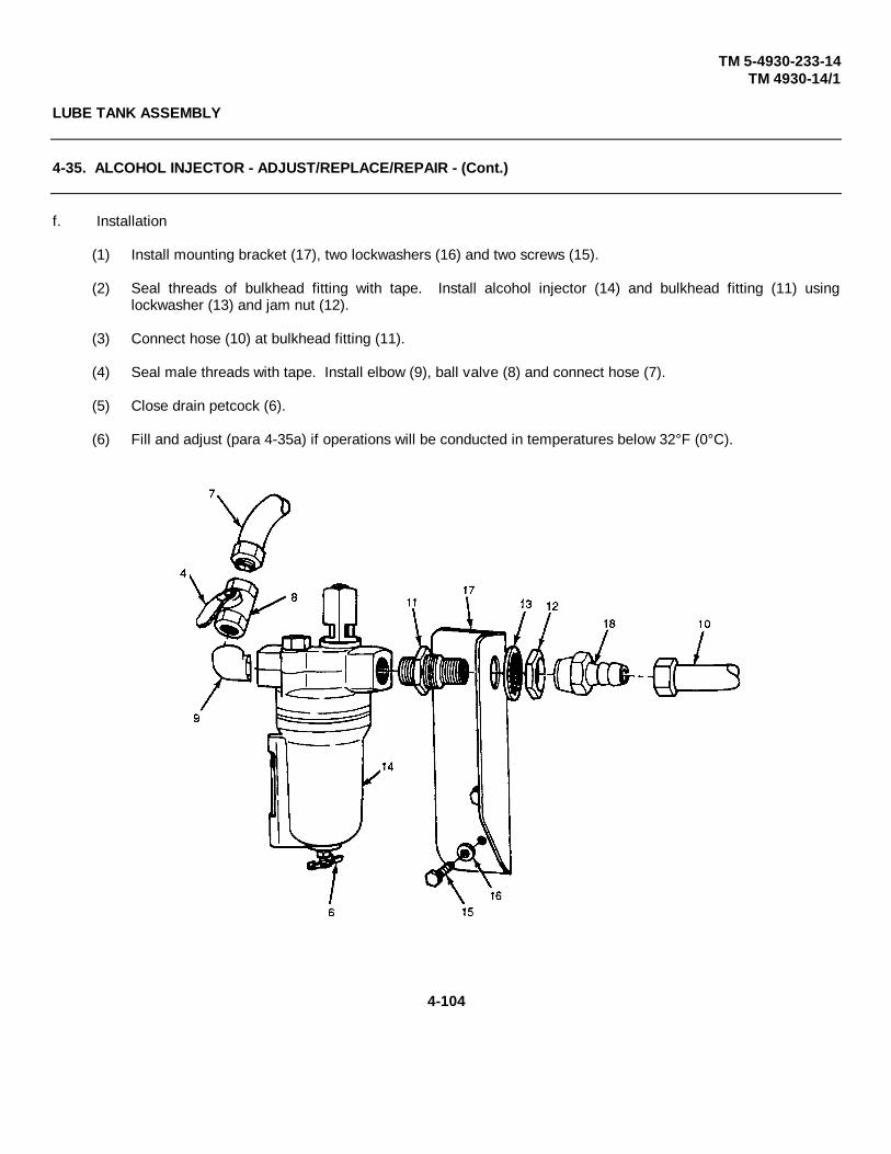
TM 5-4930-233-14TM 4930-14/1
LUBE TANK ASSEMBLY
4-35. ALCOHOL INJECTOR - ADJUST/REPLACE/REPAIR - (Cont.)
f. Installation
(1) Install mounting bracket (17), two lockwashers (16) and two screws (15).
(2) Seal threads of bulkhead fitting with tape. Install alcohol injector (14) and bulkhead fitting (11) usinglockwasher (13) and jam nut (12).
(3) Connect hose (10) at bulkhead fitting (11).
(4) Seal male threads with tape. Install elbow (9), ball valve (8) and connect hose (7).
(5) Close drain petcock (6).
(6) Fill and adjust (para 4-35a) if operations will be conducted in temperatures below 32°F (0°C).
4-104

TM 10-4930-233-14TM 4930-14/1
LUBE TANK ASSEMBLY
4-36. AIR REGULATOR - REPLACE
This task covers:
a. Removal b. Installation
INITIAL SET-UP:
Material/Parts ToolsTeflon Tape General Mechanics Tool Box(Item 18, AppE) (Section III, Item 1, AppB)
a. Removal
(1) Vent air pressure completely by turning lever (1).
4-105
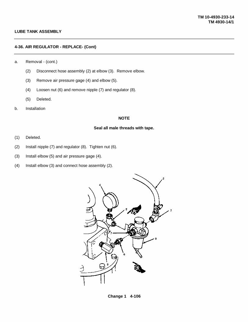
TM 10-4930-233-14TM 4930-14/1
LUBE TANK ASSEMBLY
4-36. AIR REGULATOR - REPLACE- (Cont)
a. Removal - (cont.)
(2) Disconnect hose assembly (2) at elbow (3). Remove elbow.
(3) Remove air pressure gage (4) and elbow (5).
(4) Loosen nut (6) and remove nipple (7) and regulator (8).
(5) Deleted.
b. Installation
NOTE
Seal all male threads with tape.
(1) Deleted.
(2) Install nipple (7) and regulator (8). Tighten nut (6).
(3) Install elbow (5) and air pressure gage (4).
(4) Install elbow (3) and connect hose assembly (2).
Change 1 4-106

TM 5-4930-233-14TM 4930-14/1
LUBE TANK ASSEMBLY
4-37. LOW AND HIGH PRESSURE PUMPS - REPLACE
This task covers:a. Removal b. Installation
INITIAL SET-UP:Materials/Parts Equipment Condition
Teflon Tape Air Regulator Removed NOTE(Item 18, App E) (para 4-36 The following procedure ap-
plies to the high pressureTools pump or either of the two low
General Mechanics pressure pumps.Tool Box (Section III, Item 1, AppB)
a. Removal
(1) Remove alcohol injector if needed (para 4-35).
(2) Vent lube pressure by opening valve (1). Close valve.
(3) Remove pneumatic muffler (2) and elbow (3).
(4) Disconnect lube hose assembly (4) and remove adapter (5).
(5) Loosen two clamps (6) and remove hose (7). Remove damps (6) from hose (7).
4-107
TM 5-4930-233-14TM 4930-14/1
LUBE TANK ASSEMBLY
4-37. LOW AND HIGH PRESSURE PUMPS - REPLACE - (Cont.)
a. Removal- (cont.)
(6) Remove two hose barbs (8).
(7) Remove return valve (1) and nipple (9).
(8) Remove four screws (10) and four lockwashers (11).
(9) For high pressure pump only, loosen setscrew on pickup tube collar (located inside tank).
(10) Lift out lube pump (12) and allow excess lubricant to drip into tank.
(11) For high pressure pump only, remove collar.
(12) Remove gasket (13).
b. Installation
(1) Seal all tapered threads with tape.
(2) Install gasket (13), lube pump (12), four lockwashers (11) and four screws (10). Install collar and setscrew forhigh pressure pump.
(3) Install nipple (9) and return valve (1).
(4) Install two hose barbs (8).
(5) Slide two clamps (6) onto hose (7) and install.
(6) Install adapter (5) and connect lube hose assembly (4).
(7) Install elbow (3) and pneumatic muffler (2).
(8) Install alcohol injector if removed (para 4-35).
4-108

TM 5-4930-233-14TM 4930-14/1
LUBE TANK ASSEMBLY
4-38. LUBE TANK - REPLACE/REPAIR
This task covers:a. Removal b. Disassembly c. Repair d. Assemblye. Installation
INITIAL SET-UP:Personnel Required Materials/Parts
2 Dry cleaning Solvent(Item 6, AppE)Silicon Sealant (Item 14, App E)
Equipment ConditionEnclosure removed (para 4-11) ToolsAlcohol Injector Removed (para 4-35) General Mechanics Tool BoxThree air regulators removed (para 4-36) (Section III, Item 1, App B)Low and high pressure pumps removed(para 4-37)
a. Removal
NOTEGAA Grease will have to be scooped out.
(1) Completely drain all lubricants from lube tank (1) by removing three plugs (2).
4-109

TM 5-4930-233-14TM 4930-14/1
LUBE TANK ASSEMBLY
4-38. LUBE TANK - REPLACE/REPAIR - (Cont.)
a. Removal - (cont.)
(2) Disconnect three exhaust hoses (3) and remove exhaust hose (4).
(3) Drill out four rivets (5) and remove exhaust diverter (6).
(4) Loosen clamp (7) and disconnect hose (8) at duct (9).
(5) Drill out six rivets (10) and remove duct (9).
(6) Remove eight nuts (11), eight lockwashers (12) and eight screws (13).
(7) Lift lube tank (1) off of skid.
4-110

TM 5-4930-233-14TM 4930-14/1
LUBE TANK ASSEMBLY
4-38. LUBE TANK- REPLACE/REPAIR - (Cont.)
b. Disassembly
NOTESteps (1) and (2) apply to any of three manholes
(1) Unscrew spring well (16) and remove manhole (15). Remove retainer (17), packing (14), gasket (21), gasket(18) and gasket (22).
NOTE• Remove ID plate only if illegible or if manhole latch is to be replaced.• Step 3 applies to any of three ID plates.
(2) Drill out two rivets (19) and remove ID plate (20).
4-111
TM 5-4930-233-14TM 4930-14/1
LUBE TANK ASSEMBLY
4-38. LUBE TANK - REPLACE/REPAIR - (Cont.)
c. Repair
WARINING
Clean all parts in a well ventilated area. Avoid inhaling solvent fumes and prolonged exposure ofthe skin to cleaning solvent. Failure to do so can cause severe injury or death. Do not use nearflame or excessive heat. Flash point of solvent is 100°F to 138°F (38°C to 59°C).
(1) Flush out each of three lubricant compartments in the tank using dry cleaning solvent.
(2) Inspect tank for cracks defective manhole hinges, broken weldments and other damage. Replace defectivetanks.
(3) Inspect manhole for damage, corrosion, gasket damage or wear or other conditions that could impair its sealingability. Replace parts as required.
4-112

TM 5-4930-233-14TM 4930-14/1
LUBE TANK ASSEMBLY
4-38. LUBE TANK - REPLACE/REPAIR - (Cont.)
d. Assembly
NOTEStep (1) applies to any of three ID plates.
(1) Install ID plate (20) using two rivets (19).
NOTEStep (2) applies to any of three manholes.
(2) Install retainer (1), packing (14), gasket (21), gasket (22), gasket (18) and spring well (16) and manhole (15).
4-113
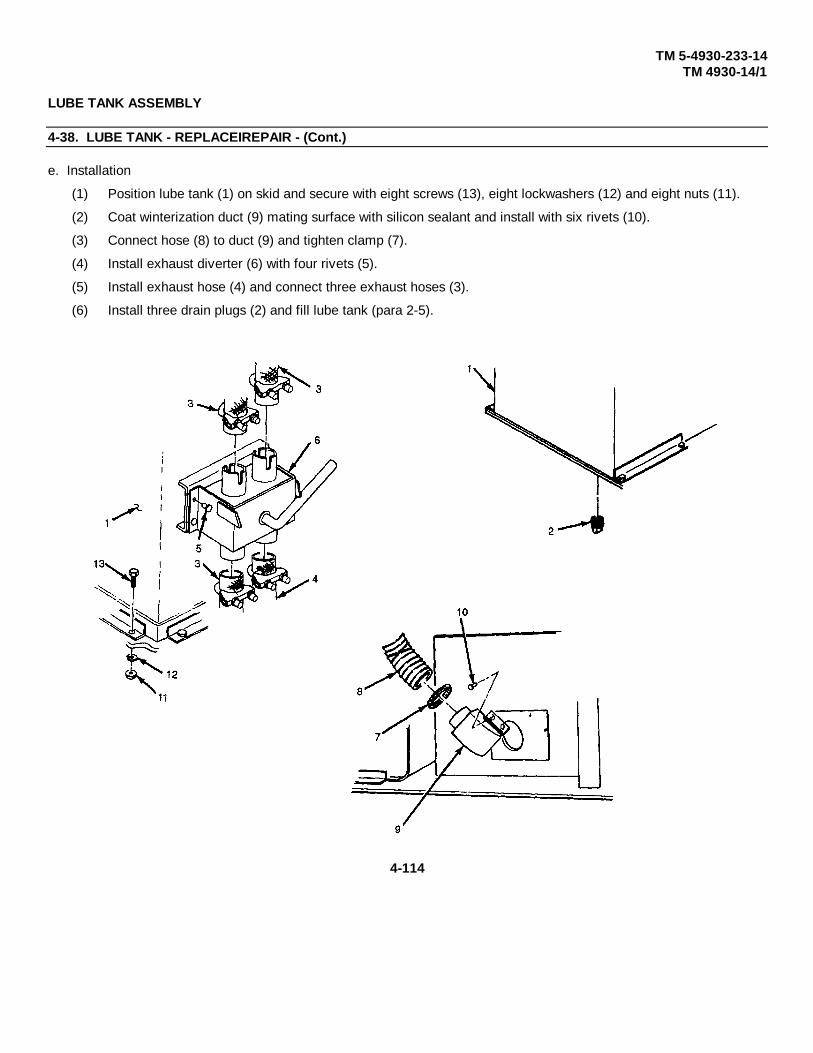
TM 5-4930-233-14TM 4930-14/1
LUBE TANK ASSEMBLY
4-38. LUBE TANK - REPLACEIREPAIR - (Cont.)
e. Installation
(1) Position lube tank (1) on skid and secure with eight screws (13), eight lockwashers (12) and eight nuts (11).
(2) Coat winterization duct (9) mating surface with silicon sealant and install with six rivets (10).
(3) Connect hose (8) to duct (9) and tighten clamp (7).
(4) Install exhaust diverter (6) with four rivets (5).
(5) Install exhaust hose (4) and connect three exhaust hoses (3).
(6) Install three drain plugs (2) and fill lube tank (para 2-5).
4-114

TM 5-4930-233-14TM 4930-14/1
WINTERIAZTION ASSEMBLY
4-39. HEATER - REPLACE
This task covers:a. Removal b. Installation
INITIAL SET-UP:Tools
General Mechanics Tool Box(Section III, Item 1, AppB)
a. Removal
(1) Disconnect fuel line quick disconnect (1).
(2) Disconnect electrical connector (2).
(3) Disconnect exhaust hose (3).
(4) Remove pin (4) and pull heater and slide (5) out of track (6).
4-115
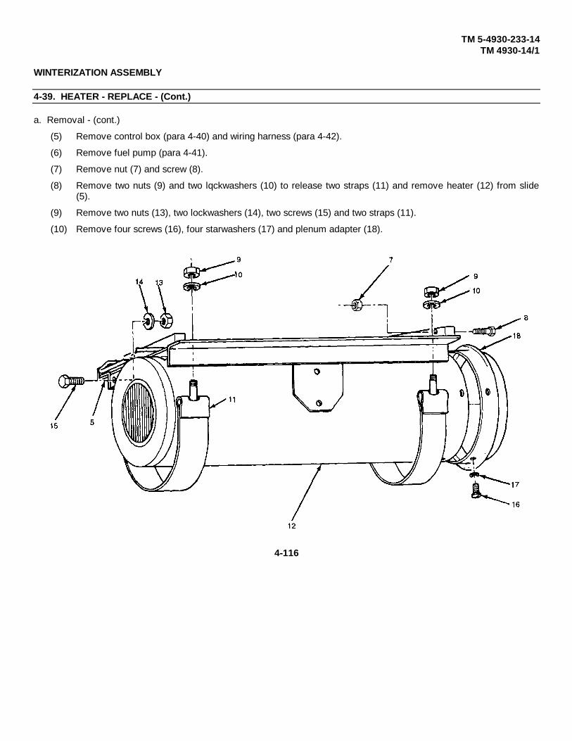
TM 5-4930-233-14TM 4930-14/1
WINTERIZATION ASSEMBLY
4-39. HEATER - REPLACE - (Cont.)
a. Removal - (cont.)
(5) Remove control box (para 4-40) and wiring harness (para 4-42).
(6) Remove fuel pump (para 4-41).
(7) Remove nut (7) and screw (8).
(8) Remove two nuts (9) and two lqckwashers (10) to release two straps (11) and remove heater (12) from slide(5).
(9) Remove two nuts (13), two lockwashers (14), two screws (15) and two straps (11).
(10) Remove four screws (16), four starwashers (17) and plenum adapter (18).
4-116

TM 5-4930-233-14TM 4930-14/1
WINTERIZATION ASSEMBLY
4-39. HEATER - REPLACE - (Cont.)
(11) Disconnect four hoses (19) at plenum (20).
(12) Remove four nuts (21), four lockwashers (22), eight washers (23), four screws (24) and slide (6).
(13) Remove four nuts (25), four lockwashers (26), eight washers (27), four screws (28) and plenum (20).
(14) Drill out rivet (29) to remove cable (30) and retainer pin (4).
4-117
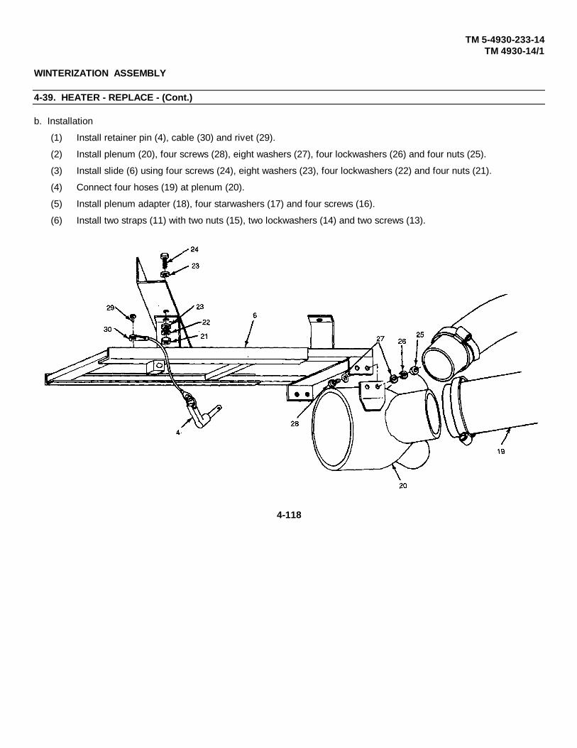
TM 5-4930-233-14TM 4930-14/1
WINTERIZATION ASSEMBLY
4-39. HEATER - REPLACE - (Cont.)
b. Installation
(1) Install retainer pin (4), cable (30) and rivet (29).
(2) Install plenum (20), four screws (28), eight washers (27), four lockwashers (26) and four nuts (25).
(3) Install slide (6) using four screws (24), eight washers (23), four lockwashers (22) and four nuts (21).
(4) Connect four hoses (19) at plenum (20).
(5) Install plenum adapter (18), four starwashers (17) and four screws (16).
(6) Install two straps (11) with two nuts (15), two lockwashers (14) and two screws (13).
4-118

TM 5-4930-233-14TM 4930-14/1
WINTERIZATION ASSEMBLY
4-39. HEATER - REPLACE - (Cont.)
(7) Install heater (12) onto slide (5) and retain with straps (11), two lockwashers (10) and two nuts (9).
(8) Install screw (8) and nut (7).
(9) Install fuel pump (para 4-41).
(10) Install control box (para 4-40) and wiring harness (para 4-42).
(11) Install heater and slide (5), into track (6) and retain using pin (4).
(12) Connect exhaust hose (3).
(13) Connect electrical connector (2).
(14) Connect fuel line (1).
4-119

TM 5-4930-233-14TM 4930-14/1
WINTERIZATION ASSEMBLY
4-40. CONTROL BOX- TEST/REPLACE
This task covers:a. Test b. Removal c. Installation
INITIAL SET-UP:General Safety Instructions Tools
General Mechanics Tool Box(Section III, Item 1, AppB)
WARNING
When working on electrical compo-nents remove all jewelry, dogtags,and metal items to avoid electricalshock and burns.
a. Test
(1) See the continuity chart (Table 4-4) and wiring diagram and check continuity at pins and connections asindicated.
(2) If the control box is defective, replace.
Table 4-4. Wiring Diagram
SWITCH MULTIMETER LEAD CONNECTIONS MULTIMETERPOSITION LEAD 1 LEAD 2 READING
Heat Switch High Pin E Pin B 0Heat Switch Low Pin E Pin B ---Control Switch Off Pin A Pin C ---Control Switch Start Pin A Pin C 0Control Switch Off Pin A Pin D ---Control Switch Start Pin A Pin D 0Control Switch Off Pin C Pin E ---Control Switch Run Pin C Pin E 0Light-Pressed to Test Pin D Pin E 0Light Pin E Box Enclosure 0
Pin D Connector Wire 400
4-120
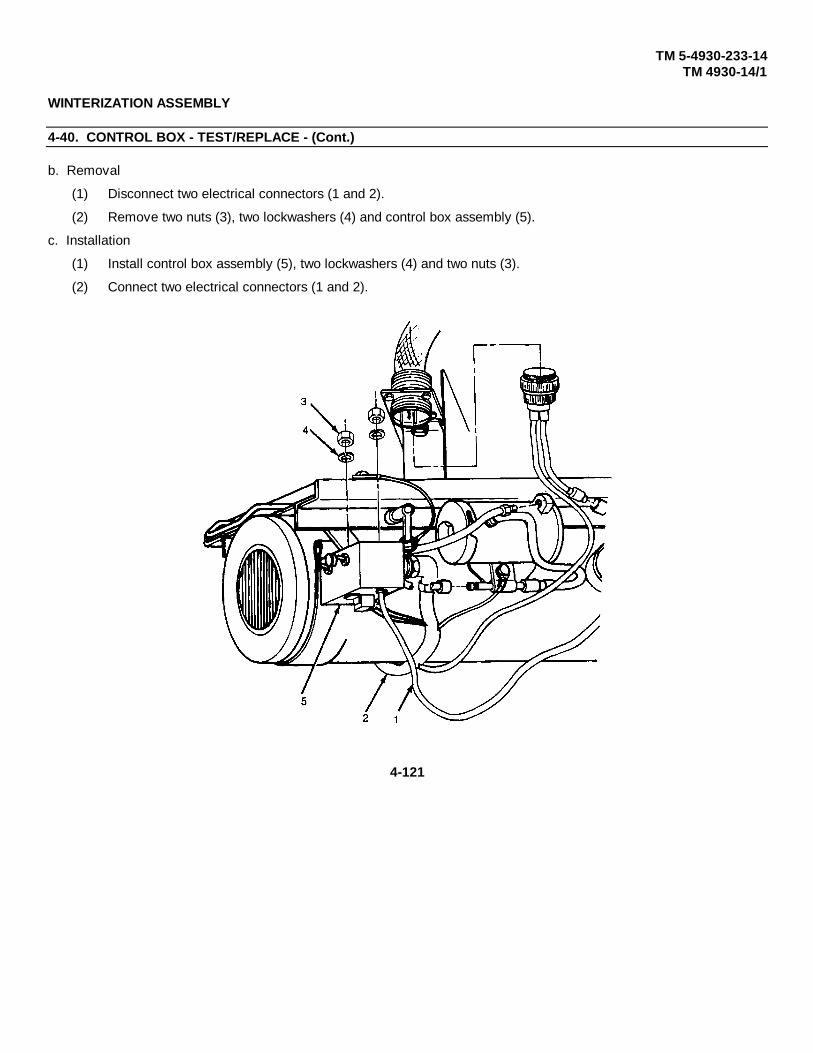
TM 5-4930-233-14TM 4930-14/1
WINTERIZATION ASSEMBLY
4-40. CONTROL BOX - TEST/REPLACE - (Cont.)
b. Removal
(1) Disconnect two electrical connectors (1 and 2).
(2) Remove two nuts (3), two lockwashers (4) and control box assembly (5).
c. Installation
(1) Install control box assembly (5), two lockwashers (4) and two nuts (3).
(2) Connect two electrical connectors (1 and 2).
4-121

TM 5-4930-233-14TM 4930-14/1
WINTERIZATION ASSEMBLY
4-41. FUEL PUMP - TEST/REPLACE
This task covers:a. Test b. Removal c. Installation
INITIAL SET-UP:General Safety Instructions Tools
General Mechanics Tool BoxWARNING (Section III, Item 1, AppB)
MultimeterDo not use open flame or smoke (Section III, Item 4, AppB)when working on fuel system. Anexplosion may occur, causingsevere injury or death.
a. Test
(1) Disconnect electrical connector (1) at relay and fuel line (2).
(2) Place one multimeter lead in electrical connector and one on the fuel pump mount, check for continuity.
(3) Replace fuel pump if multimeter reading is infinity (00) or if fuel pump does not operate.
4-122

TM 5-4930-233-14TM 4930-14/1
WINTERIZATION ASSEMBLY
4-41. FUEL PUMP - TEST/REPLACE - (Cont.)
b. Removal
(1) Disconnect electrical lead at relay (1).
(2) Disconnect fuel line (2).
(3) Remove hose assembly (3) and elbow (4), if necessary.
(4) Loosen two clamps (5) and remove two hose barbs (6) from hose (7). Remove clamps.
(5) Remove two nuts (8), two lockwashers (9), two screws (10) and fuel pump (11).
(6) Remove coupling (12) from fuel pump.
c. Installation
(1) Install coupling (12) at fuel pump (11).
(2) Install fuel pump (11), two screws (10), two lockwashers (9) and two nuts (8).
(3) Slide two clamps (5) onto hose (7) and install two hose barbs (6).
(4) Install elbow (4) and hose assembly (3), if necessary.
(5) Connect fuel line (2) and electrical connector (1).
(6) Reconnect electrical lead at relay (1).
4-123

TM 5-4930-233-14TM 4930-14/1
WINTERIZATION ASSEMBLY
4-42. WIRING HARNESS - TEST/REPLACE/REPAIR
This task covers:a. Test b. Removal c. Repair d. Installation
INITIAL SET-UP:General Safety Instructions Tools
General Mechanics Tool BoxWARINING (Section III, Item 1, AppB)
MultimeterWhen working on electrical compo- (Section III, Item 4, AppB)nents remove all jewelry, dogtags , (Section III,and metal items to avoid electricalshock and burns.
a. Test
See wiring diagram and wire list (Table 4-5). Perform continuity tests on individual wires. Replace or repair wireswith no continuity.
Table 4-5. Wire List
TERMINATION TERMINATION AWG LENGTHFROM TERMINAL TYPE TO TERMINAL TYPE SIZE IN. CM
Heater MS3106E18-115 Fuel Pump MS79281 14 18 45.7Heater --- Control Box MS3108E18-115 14 23 58.4Fuel Pump MS27144-1 Control Box --- 14 4 10.6Connector MS3106E16-115 Ground Circuit --- 14 7 17.8Connector --- Control Box MS27144-1 14 5 12.7Control Box MS79281 Ground Circuit --- 14 11 27.9Connector MS3100E16-11P Starter MS79281 14 72 183Connector --- Ground MS79281 14 72 183
4-124

TM 5-4930-233-14TM 4930-14/1
WINTERIZATION ASSEMBLY
4-42. WIRING HARNESS - TEST/REPLACE/REPAIR - (Cont.)
WIRING DIAGRAM
b. Removal
Tag and disconnect individual wires and connectors in accordance with the wiring diagram.
c. Repair
(1) Replace any wires or connectors that are defective or show signs of wear or damage.
(2) See paragraph 4-24 for general wire repair instructions.
(3) See Table 4-5 Wire List for wire lengths and terminal information when individual wires are replaced.
d. Installation
See wiring diagram and tags, and connect the wire leads and connectors. Remove tags.
4-125
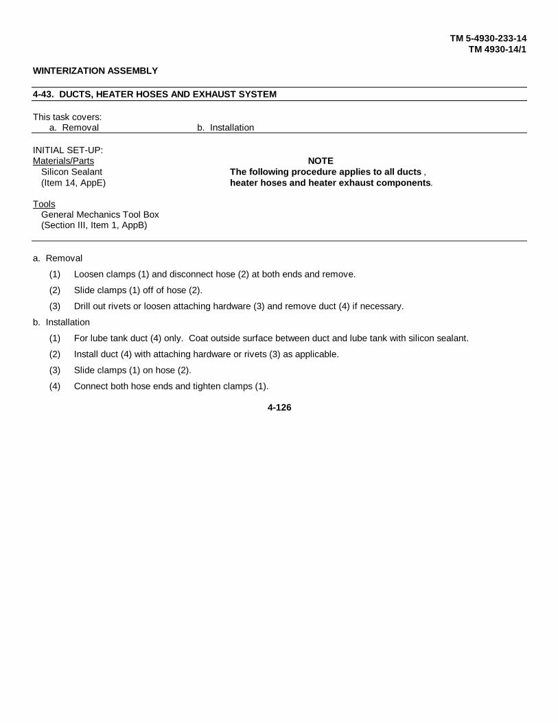
TM 5-4930-233-14TM 4930-14/1
WINTERIZATION ASSEMBLY
4-43. DUCTS, HEATER HOSES AND EXHAUST SYSTEM
This task covers:a. Removal b. Installation
INITIAL SET-UP:Materials/Parts NOTE
Silicon Sealant The following procedure applies to all ducts ,(Item 14, AppE) heater hoses and heater exhaust components.
ToolsGeneral Mechanics Tool Box(Section III, Item 1, AppB)
a. Removal
(1) Loosen clamps (1) and disconnect hose (2) at both ends and remove.
(2) Slide clamps (1) off of hose (2).
(3) Drill out rivets or loosen attaching hardware (3) and remove duct (4) if necessary.
b. Installation
(1) For lube tank duct (4) only. Coat outside surface between duct and lube tank with silicon sealant.
(2) Install duct (4) with attaching hardware or rivets (3) as applicable.
(3) Slide clamps (1) on hose (2).
(4) Connect both hose ends and tighten clamps (1).
4-126

TM 5-4930-233-14TM 4930-14/1
4-127

TM 5-4930-233-14TM 4930-14/1
LUBE AND PNEUMATIC PIPING
4-44. LUBE PIPING - REPLACE/REPAIR
This task covers:a. Removal b. Repair c. Installation
INITIAL SET-UP:Materials/Parts NOTE
Teflon Tape (Item 18, App E) The following procedure appliesDry Cleaning Solvent (Item 6, App E) to any hose line or fitting shown .Cloth (hem 22, App E)
ToolsGeneral Mechanics Tool Box (Section III, Item 1, App B)
a. Removal
(1) Vent lube pressure by opening three valves (1). Close valves after pressure is gone.
4-128
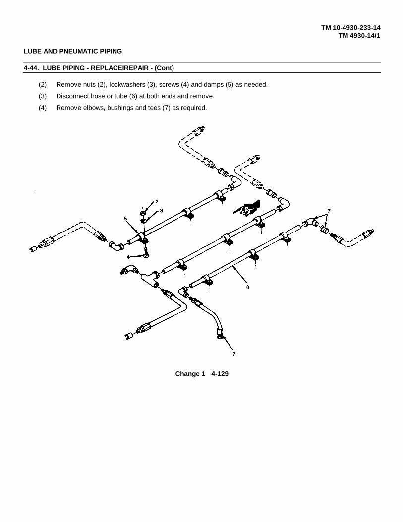
TM 10-4930-233-14TM 4930-14/1
LUBE AND PNEUMATIC PIPING
4-44. LUBE PIPING - REPLACEIREPAIR - (Cont)
(2) Remove nuts (2), lockwashers (3), screws (4) and damps (5) as needed.
(3) Disconnect hose or tube (6) at both ends and remove.
(4) Remove elbows, bushings and tees (7) as required.
Change 1 4-129
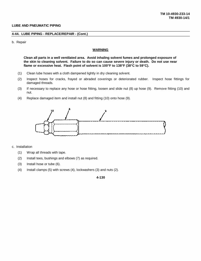
TM 10-4930-233-14TM 4930-14/1
LUBE AND PNEUMATIC PIPING
4-44. LUBE PIPING - REPLACE/REPAIR - (Cont.)
b. Repair
WARNING
Clean all parts in a well ventilated area. Avoid inhaling solvent fumes and prolonged exposure ofthe skin to cleaning solvent. Failure to do so can cause severe injury or death. Do not use nearflame or excessive heat. Flash point of solvent is 100°F to 138°F (38°C to 59°C).
(1) Clean lube hoses with a cloth dampened lightly in dry cleaning solvent.
(2) Inspect hoses for cracks, frayed or abraded coverings or deteriorated rubber. Inspect hose fittings fordamaged threads.
(3) If necessary to replace any hose or hose fitting, loosen and slide nut (8) up hose (9). Remove fitting (10) andnut.
(4) Replace damaged item and install nut (8) and fitting (10) onto hose (9).
c. Installation
(1) Wrap all threads with tape.
(2) Install tees, bushings and elbows (7) as required.
(3) Install hose or tube (6).
(4) Install clamps (5) with screws (4), lockwashers (3) and nuts (2).
4-130
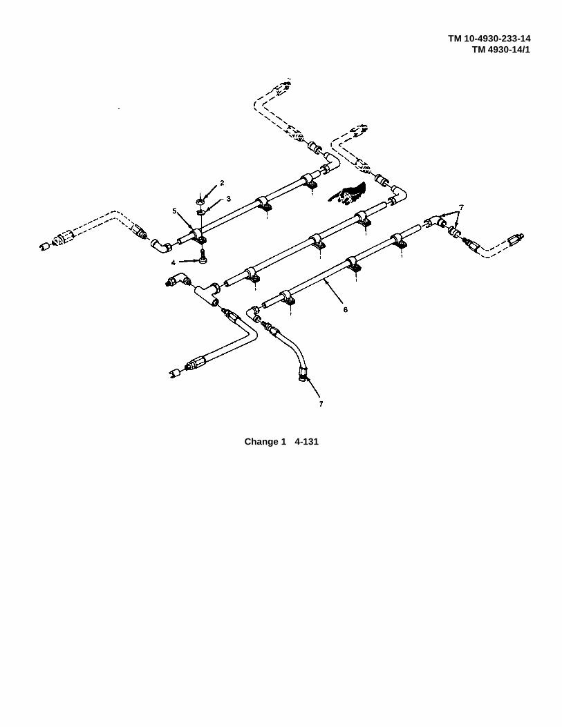
TM 10-4930-233-14TM 4930-14/1
Change 1 4-131

TM 10-4930-233-14TM 4930-14/1
LUBE AND PNEUMATIC PIPING
4-45. PNEUMATIC PIPING - REPLACE/REPAIR
This task covers:
a. Removal b. Repair c. Installation
INITIAL SET-UP:
Material Parts NOTETeflon Tape (Item 18, App E) The following procedure appliesDry Cleaning Solvent (Item 6, App E) to any hose line or fitting shown .Cloth (Item 22, App E)
ToolsGeneral Mechanics Tool Box (Section III, Item 1, App B)
a. Removal
(1) Drain air pressure completely by turning lever (1).
4-132
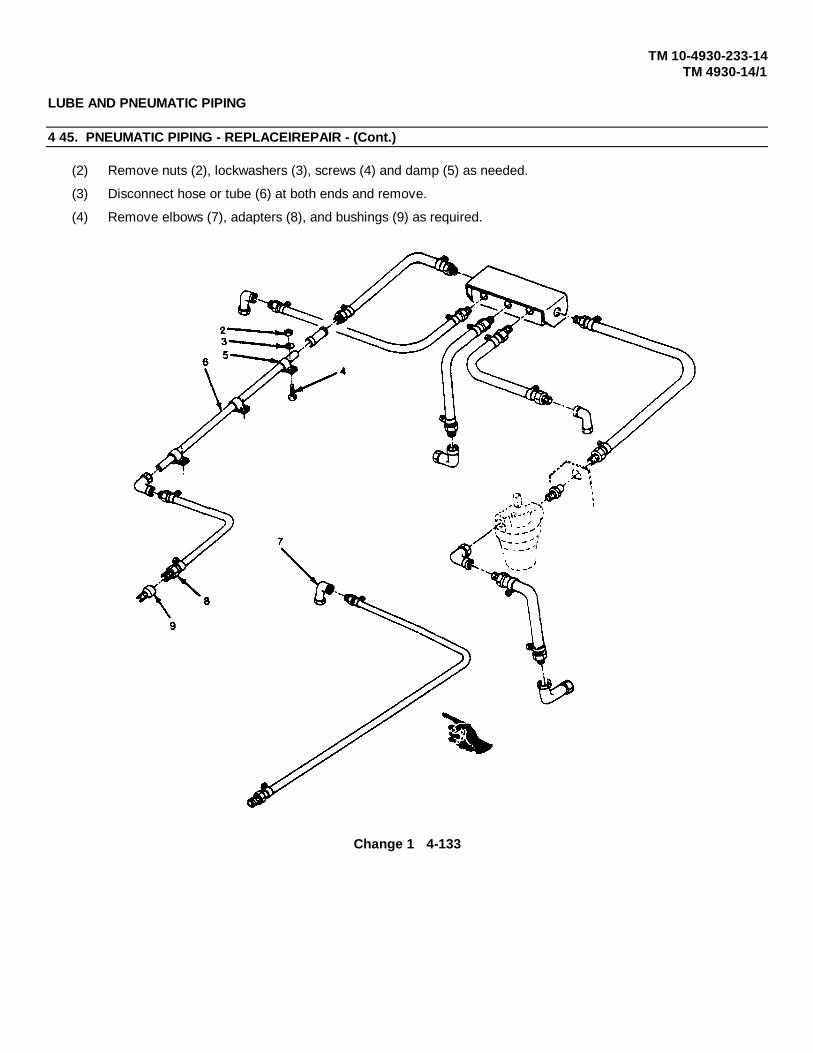
TM 10-4930-233-14TM 4930-14/1
LUBE AND PNEUMATIC PIPING
4 45. PNEUMATIC PIPING - REPLACEIREPAIR - (Cont.)
(2) Remove nuts (2), lockwashers (3), screws (4) and damp (5) as needed.
(3) Disconnect hose or tube (6) at both ends and remove.
(4) Remove elbows (7), adapters (8), and bushings (9) as required.
Change 1 4-133

TM 10-4930-233-14TM 4930-14/1
LUBE AND PNEUMATIC PIPING
4-45. PNEUMATIC PIPING - REPLACE/REPAIR - (Cont)
b. Repair
WARNING
Clean all parts in a well ventilated area. Avoid inhaling solvent fumes and prolonged exposure ofthe skin to cleaning solvent. Failure to do so can cause severe injury or death. Do not use nearflame or excessive heat. Flash point of solvent is 100°F to 138°F (38°C to 59°C).
(1) Clean all hoses with a cloth dampened lightly in dry cleaning solvent.
(2) Inspect hoses for cracks, frayed or abraded coverings or deteriorated rubber. Inspect hose fittings fordamaged threads.
(3) If necessary to replace any hoses or hose fittings, loosen damp (10) and remove along with fitting (11) fromhose (12).
(4) Replace damaged item and install clamp (10) and fitting (11) onto hose (12).
4-134

TM 10-4930-233-14TM 4930-14/1
LUBE AND PNEUMATIC PIPING
4-45. PNEUMATIC PIPING - REPLACE/REPAIR - (Cont.)
c. Installation
(1) Wrap all threads with tape.
(2) Install bushings (9), adapters (8) and elbows (7) as required.
(3) Install hose or tube (6).
(4) Install clamps (5) with screws (4), lockwashers (3) and nuts (2).
Change 1 4-135

TM 10-4930-233-14TM 4930-14/1
TRAILER ASSEMBLY
4-46. TRAILER COMPONENTS
This task covers:
a. Removal b. Installation
INITIAL SET-UP:
Materials/Prints ToolsTape, masking (Item 17, AppE) General Mechanics Tool Box
(Section III, Item 1, AppB)
a. Removal
NOTEStep 1 applies to the two rear reflectors.
(1) Remove two rivets (1) and remove rear reflector (2).
NOTEStep 2 applies to any of the four side reflectors.
(2) Drill out two rivets (3) and remove side reflector (4).
4-136

TM 5-4930-233-14TM 4930-14/1
TRAILER ASSEMBLY
4-46. TRAILER COMPONENTS - (Cont.)
NOTE
Steps 3 and 4 apply to any of four lifting rings.
(3) Unscrew lifting eye (5) and remove.
(4) Remove two nuts (6), two lockwashers (7), two flatwashers (9), two screws (8) and plate nut (10).
(5) Open clamp (11) and remove fire extinguisher (12).
(6) Remove two nuts (13), two lockwashers (14), two screws (15) and extinguisher bracket (16).
4-137

TM 5-4930-233-14TM 4930-14/1
TRAILER ASSEMBLY
4-46. TRAILER COMPONENTS - (Cont.)
b. Installation
(1) Install extinguisher bracket (16), two screws (15), two lockwashers (14) and two nuts (13).
(2) Install fire extinguisher (12) and close clamp (11).
NOTE
Steps 3 and 4 apply to any of four lifting rings.
(3) Install plate nut (10), two flatwashers (9), two screws (8), two lockwashers (7) and two nuts (6).
NOTE
Taping lockwasher and nut to rear of plate will aid in installation of lifting eye.
(4) Install lifting eye (5).
4-138

TM 5-4930-233-14TM 4930-14/1
TRAILER ASSEMBLY
4-46. TRAILER COMPONENTS - (Cont.)
NOTE
Step 5 applies to the two rear reflectors.
(5) Install rear reflector (2) with two rivets (1).
NOTE
Step 6 applies to any of the four side reflectors.
(6) Install side reflector (4) with two rivets (3).
4-139

TM 5-4930-233-14TM 4930-14/1
AIR BRAKE ASSEMBLY
4-47. COUPLER (GLAD HAND) - REPLACE/REPAIR
This task covers:
a. Removal b. Disassembly c. Repair d. Assemblye. Installation
INITIAL SET-UP:
Materials/Parts NOTE
Teflon tape The following procedure applies to(Item 18, App E) either the emergency or serviceCloth (Item 22, App E) brake coupler.
ToolsGeneral Mechanics Tool Box(Section III, Item 1, App B)
a. Removal
Unscrew coupler (glad hand) (1) from fitting (2) and cap line.
b. Disassembly
Pry out glad hand seal (1).
4-140

TM 5-4930-233-14TM 4930-14/1
AIR BRAKE ASSEMBLY
4-47. COUPLER (GLAD HAND) - REPLACE/REPAIR
c. Repair
(1) Remove all buildup of dirt, grease, etc., by wiping with a soft cloth.
(2) Inspect for cracks, dents, holes, warps, rust and corrosion. Replace coupler.
d. Assembly
Install glad hand seal (1).
e. Installation
Wrap fitting (2) threads with tape and install coupler (glad hand) (1).
4-141
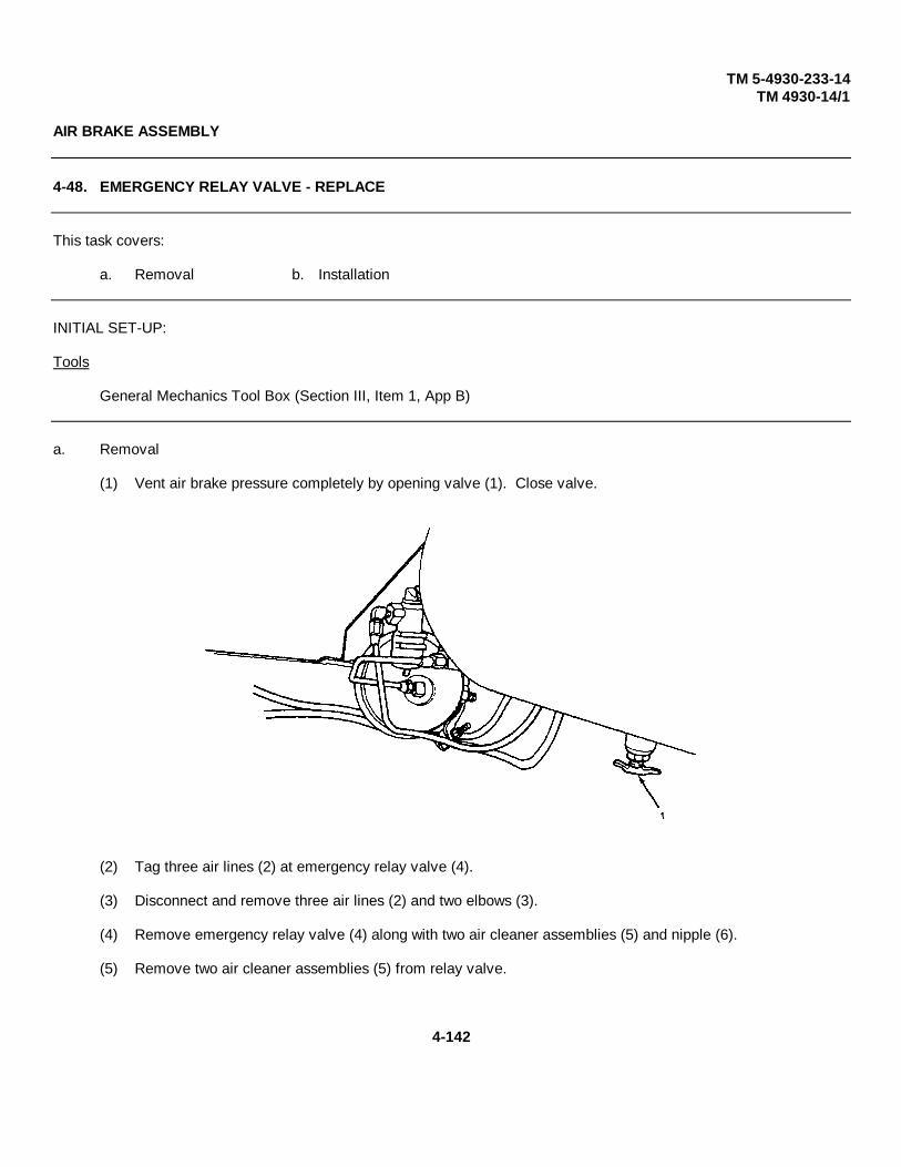
TM 5-4930-233-14TM 4930-14/1
AIR BRAKE ASSEMBLY
4-48. EMERGENCY RELAY VALVE - REPLACE
This task covers:
a. Removal b. Installation
INITIAL SET-UP:
Tools
General Mechanics Tool Box (Section III, Item 1, App B)
a. Removal
(1) Vent air brake pressure completely by opening valve (1). Close valve.
(2) Tag three air lines (2) at emergency relay valve (4).
(3) Disconnect and remove three air lines (2) and two elbows (3).
(4) Remove emergency relay valve (4) along with two air cleaner assemblies (5) and nipple (6).
(5) Remove two air cleaner assemblies (5) from relay valve.
4-142
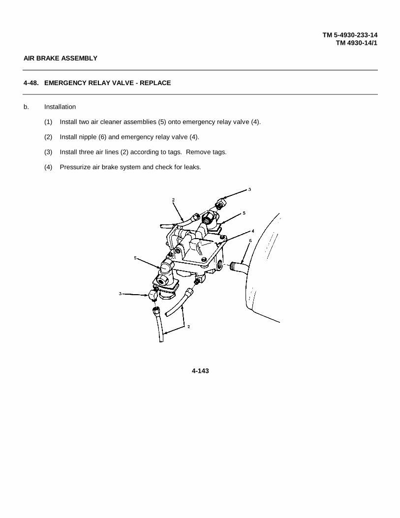
TM 5-4930-233-14TM 4930-14/1
AIR BRAKE ASSEMBLY
4-48. EMERGENCY RELAY VALVE - REPLACE
b. Installation
(1) Install two air cleaner assemblies (5) onto emergency relay valve (4).
(2) Install nipple (6) and emergency relay valve (4).
(3) Install three air lines (2) according to tags. Remove tags.
(4) Pressurize air brake system and check for leaks.
4-143

TM 5-4930-233-14TM 4930-14/1
AIR BRAKE ASSEMBLY
4-49. AIR SUPPLY VALVE - REPLACE
This task covers:
a. Removal b. Installation
INITIAL SET-UP:
Tools
General Mechanics Tool Box (Section III, Item 1, App B)
a. Removal
(1) Vent air brake pressure completely by opening valve (1). Close valve.
(2) Tag, disconnect and remove two air lines (2), nipple (3) and elbow (4).
(3) Remove knob (5), jamnut (6), washer (7) and air supply valve assembly (8).
4-144
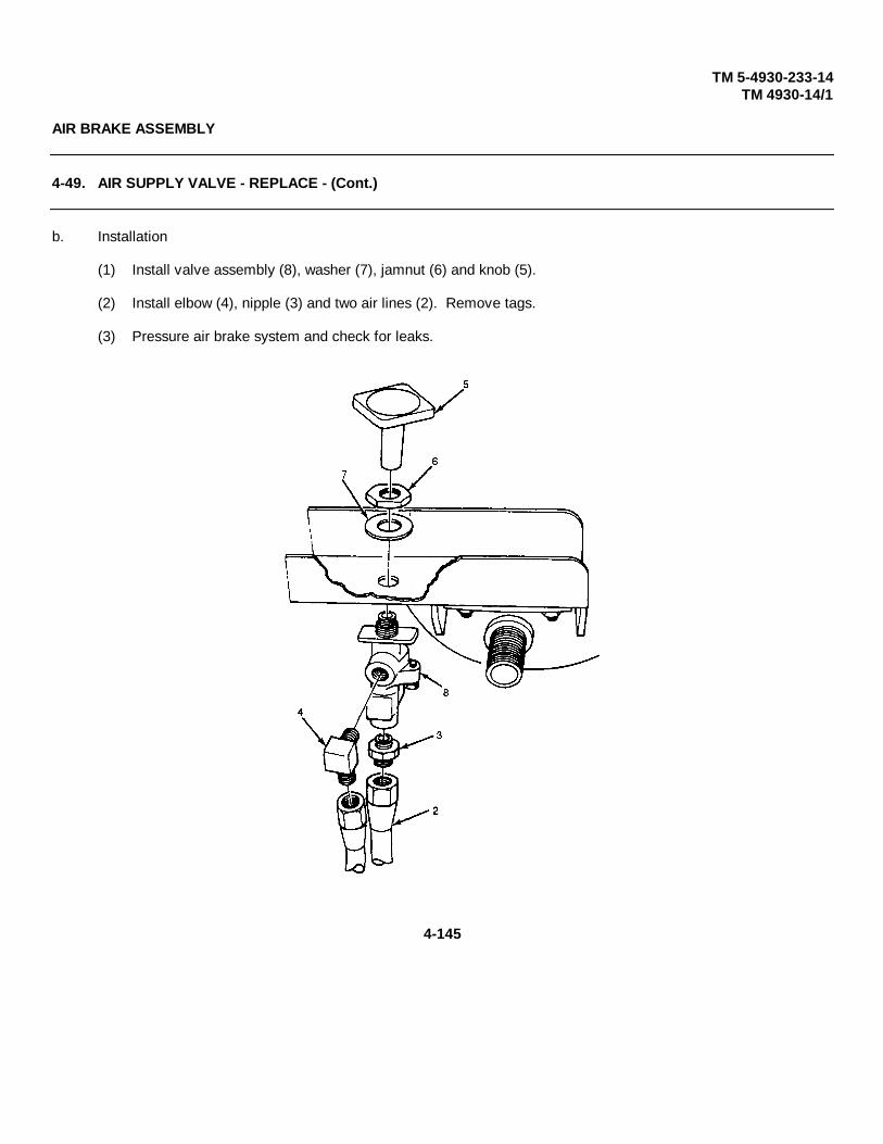
TM 5-4930-233-14TM 4930-14/1
AIR BRAKE ASSEMBLY
4-49. AIR SUPPLY VALVE - REPLACE - (Cont.)
b. Installation
(1) Install valve assembly (8), washer (7), jamnut (6) and knob (5).
(2) Install elbow (4), nipple (3) and two air lines (2). Remove tags.
(3) Pressure air brake system and check for leaks.
4-145

TM 5-4930-233-14TM 4930-14/1
AIR BRAKE ASSEMBLY
4-50. AIR CLEANER ASSEMBLY - REPLACE/REPAIR
This task covers:
a. Removal b. Disassembly c. Repair d. Assemblye. Installation
INITIAL SET-UP:
NOTE
The following procedure applies toeither of two air cleaner assemblies.The air cleaner does not need to beremoved to replace the filter element.
Tools
General Mechanics Tool Box (Section III, Item 1, App B)
a. Removal
(1) Vent air brake system pressure completely by opening valve (1). Close valve.
4-146

TM 5-4930-233-14TM 4930-14/1
AIR BRAKE ASSEMBLY
4-50. AIR CLEANER ASSEMBLY - REPLACE/REPAIR - (Cont.)
(2) Tag, disconnect and remove three air lines (2).
(3) Remove emergency relief valve (3) along with two air cleaner assemblies (4).
(4) Remove elbow (5) and air cleaner assembly (4).
b. Disassembly
(1) Remove plug (6), nut (7) and preformed packing (8).
(2) Remove spring (9), washer (10) and filter element (11) from housing (12).
4-147

TM 5-4930-233-14TM 4930-14/1
AIR BRAKE ASSEMBLY
4-50. AIR CLEANER ASSEMBLY - REPLACE/REPAIR - (Cont.)
c. Repair
(1) Discard filter element (11).
(2) Inspect spring (9) for damage or loss of tension. Discard if defective.
(3) Inspect all components for damage. Replace any damaged item.
d. Assembly
(1) Install filter (11) and washer (10) to housing (12).
(2) Install spring (9), preformed packing (8), nut (7) and plug (6).
4-148

TM 5-4930-233-14TM 4930-14/1
AIR BRAKE ASSEMBLY
4-50. AIR CLEANER ASSEMBLY - REPLACE/REPAIR - (Cont.)
e. Installation
(1) Install air cleaner assembly (4) and elbow (5) onto emergency relief valve (3).
(2) Install emergency relief valve (3).
(3) Install three air lines (2). Remove tags.
(4) Pressure air brake system and check for leaks.
4-149

TM 5-4930-233-14TM 4930-14/1
AIR BRAKE ASSEMBLY
4-51. BRAKE LINES AND HOSES - REPLACE
This task covers:
a. Removal b. Installation
INITIAL SET-UP:
NOTETools
The following procedure applies General Mechanics Tool Boxto any hose, line or fitting. (Section III, Item 1, App B)
a. Removal
(1) Vent air brake pressure completely by opening valve (1). Close valve.
(2) Remove rivets, clamps or straps (2) as needed.
(3) Disconnect hose or tube (3) at either end.
(4) Remove elbows, tees or adapters (4) as required.
(5) Remove two nuts (5) and two flatwashers (6).
4-150

TM 5-4930-233-14TM 4930-14/1
4-151

TM 5-4930-233-14TM 4930-14/1
AIR BRAKE ASSEMBLY
4-51. BRAKE LINES AND HOSES - REPLACE - (Cont.)
b. Installation
(1) Install two nuts (5) and two flatwashers (6).
(2) Install adapters, tees, or elbows (4).
(3) Connect hose or tube (3) at either end.
(4) Install straps, clamps and rivets (2) as required.
(5) Bleed and adjust brakes (para. 4-58) if hydraulic lines tubes or fittings were removed.
(6) If air lines were removed, pressurize air brake system and check for leaks.
4-152
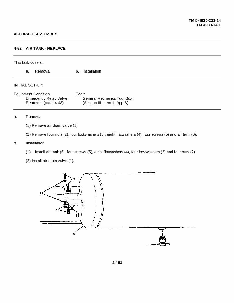
TM 5-4930-233-14TM 4930-14/1
AIR BRAKE ASSEMBLY
4-52. AIR TANK - REPLACE
This task covers:
a. Removal b. Installation
INITIAL SET-UP:
Equipment Condition ToolsEmergency Relay Valve General Mechanics Tool BoxRemoved (para. 4-48) (Section III, Item 1, App B)
a. Removal
(1) Remove air drain valve (1).
(2) Remove four nuts (2), four lockwashers (3), eight flatwashers (4), four screws (5) and air tank (6).
b. Installation
(1) Install air tank (6), four screws (5), eight flatwashers (4), four lockwashers (3) and four nuts (2).
(2) Install air drain valve (1).
4-153

TM 5-4930-233-14TM 4930-14/1
WIRING HARNESS OR TRAILER ELECTRICAL
4-53. JUNCTION BOX - TEST/REPLACE
This task covers:
a. Test b. Removal c. Installation
INITIAL SET-UP:
General Safety Instructions Equipment ConditionAir Tank Removed (para 4-52)
WARNING ToolsGeneral Mechanics Tool Box
When working on electrical compo- (Section III, Item 1, App B)nents remove all jewelry, dogtags,and metal items to avoid electricalshock and burns.
a. Test
(1) Open junction box (1) by removing screws (2) and sliding latches (3) out of the way.
NOTE
The lube and service unit trailer can operate on 12 Vdc (commercial mode) or 24Vdc (military mode). Do steps 2 through 6 if malfunction occurred while operating inmilitary mode. Go to step 7 for testing commercial mode.
(2) Hook up intervehicular cable at military style (24 Vdc) vehicle.
(3) Turn on towing vehicle headlights, and clearance lights. Step on brake.
(4) See the power output chart (Table 4-6) and junction box wiring diagram and check power outputsfor military mode only.
4-154

TM 5-4930-233-14TM 4930-14/1
WIRING HARNESS OR TRAILER ELECTRICAL
4-53. JUNCTION BOX - TEST/REPLACE - (Cont.)
(5) If voltage is not present at any location, replace junction box.
(6) If voltage at terminals 1 and 2 is above 12 Vdc replace junction box.
(7) Hook up intervehicular cable at commercial style (12 Vdc) connection.
(8) Turn on towing vehicle headlights and clearance lights. Step on brake.
(9) See the power output chart (Table 4-6) and junction box wiring diagram and check power outputsfor commercial and military modes. It will be necessary to activate the appropriate turn signals totest terminals 3 and 4.
(10) If voltage is not present at any location, replace junction box.
4-155

TM 5-4930-233-14TM 4930-14/1
WIRING HARNESS OR TRAILER ELECTRICAL
4-53. JUNCTION BOX - TEST/REPLACE - (Cont.)
b. Removal
(1) Insure that intervehicular connector is disconnected.
(2) Open junction box (1) loosen screws (2) and slide latches (3) out of the way.
(3) Tag and disconnect six 12 volt intervehicular electrical leads (4) by loosening nuts (5) and screw (6).
(4) Tag and disconnect six 24 volt intervehicular electrical leads (7) by loosening nuts (5) and screw (6).
(5) Tag and disconnect five trailer harness electrical leads (8) by loosening screws (6).
(6) Remove three nuts (9), three washers (10), three grommets (11), trailer electrical harness (12), 12volt intervehicular cable (13) and 24 volt intervehicular cable (14).
(7) Remove eight nuts (15), four lockwashers (16), four screws (17) and junction box (1).
c. Installation
(1) Install junction box (1), four screws (17), four lockwashers (16) and eight nuts (15).
(2) Slide three nuts (9), three washers (10) and three grommets (11) onto trailer electrical harness (12),12 volt intervehicular cable (13) and 24 volt intervehicular cable (14).
(3) Install trailer electrical harness (12), 12 volt intervehicular cable (13) and 24 volt intervehicular cable(14) into junction box (1) and tighten nuts (9).
(4) Connect five trailer electrical leads (8) and remove tags.
(5) Connect six 24 volt intervehicular electrical leads (7) and remove tags.
(6) Connect six 12 volt intervehicular electrical leads (4) and remove tags.
(7) Close junction box (1) and tighten latches (3) by tightening screws (2).
Change 1 4-156

TM 5-4930-233-14TM 4930-14/1
Table 4-6. Power Output Chart
4-157

TM 5-4930-233-14TM 4930-14/1
WIRING HARNESS OR TRAILER ELECTRICAL
4-54. CLEARANCE LIGHT - TEST/REPLACE
This task covers:
a. Test b. Removal c. Installation
INITIAL SET-UP:
General Safety Instructions NOTE
The following procedureWARNING applies to any of seven
clearance lights.When working on electrical compo-nents remove all jewelry, dogtags,and metal items to avoid electricalshock and burns.
ToolsGeneral Mechanics Tool Box (Section III, Item 1, App B)Multimeter (Section III, Item 4, App B)
a. Test
(1) Remove clearance light (para. 4-54b.)
(2) Place multimeter leads in electrical pin contacts (1 and 2).
(3) Check for continuity. If continuity is not present, replace clearance light.
4-158

TM 5-4930-233-14TM 4930-14/1
WIRING HARNESS OR TRAILER ELECTRICAL
4-54. CLEARANCE LIGHT - TEST/REPLACE - (Cont.)
b. Removal.
(1) Pull light (3) out of grommet (4).
(2) Disconnect electrical connector (5) and remove light (3).
(3) Remove grommet (4).
c. Installation
(1) Position grommet (4).
(2) Connect electrical connector (5) to light (3).
(3) Push light (3) into grommet (4) to install.
4-159
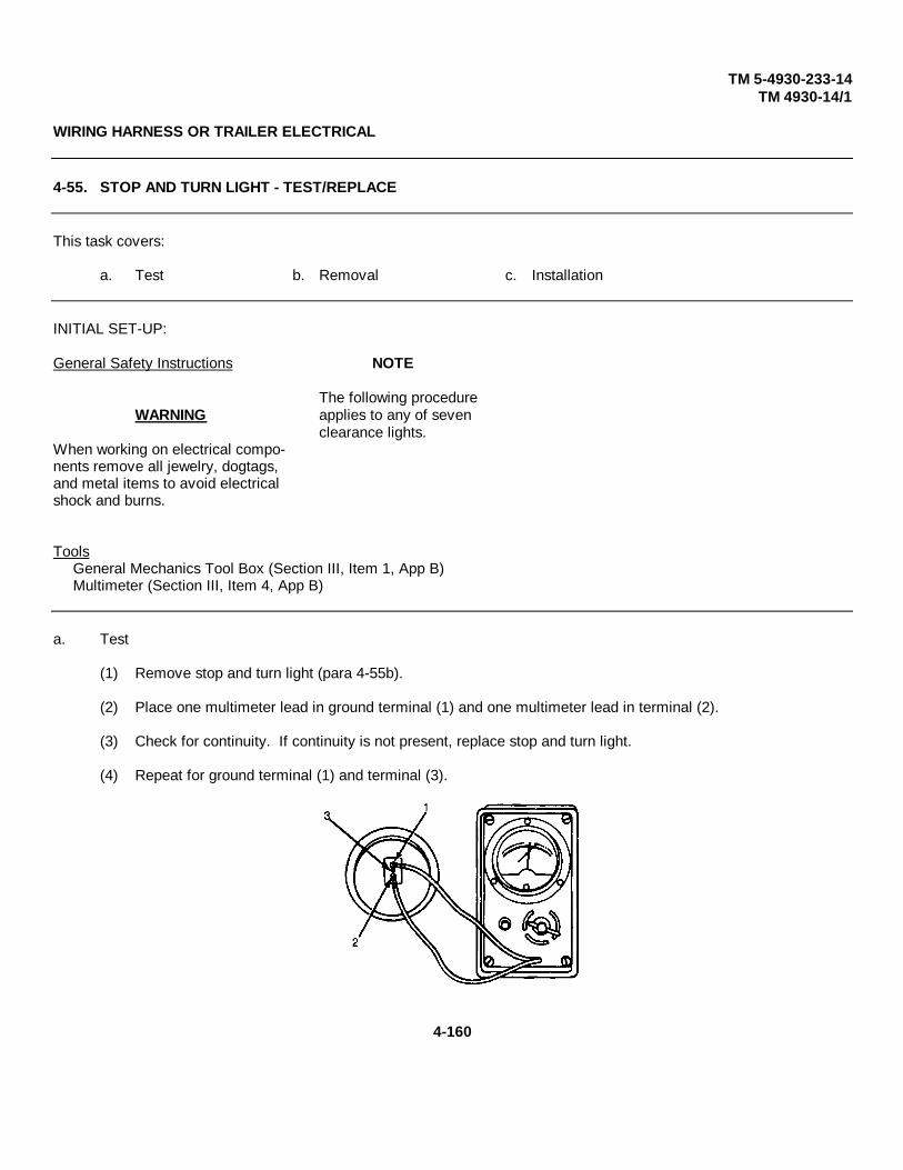
TM 5-4930-233-14TM 4930-14/1
WIRING HARNESS OR TRAILER ELECTRICAL
4-55. STOP AND TURN LIGHT - TEST/REPLACE
This task covers:
a. Test b. Removal c. Installation
INITIAL SET-UP:
General Safety Instructions NOTE
The following procedureWARNING applies to any of seven
clearance lights.When working on electrical compo-nents remove all jewelry, dogtags,and metal items to avoid electricalshock and burns.
ToolsGeneral Mechanics Tool Box (Section III, Item 1, App B)Multimeter (Section III, Item 4, App B)
a. Test
(1) Remove stop and turn light (para 4-55b).
(2) Place one multimeter lead in ground terminal (1) and one multimeter lead in terminal (2).
(3) Check for continuity. If continuity is not present, replace stop and turn light.
(4) Repeat for ground terminal (1) and terminal (3).
4-160
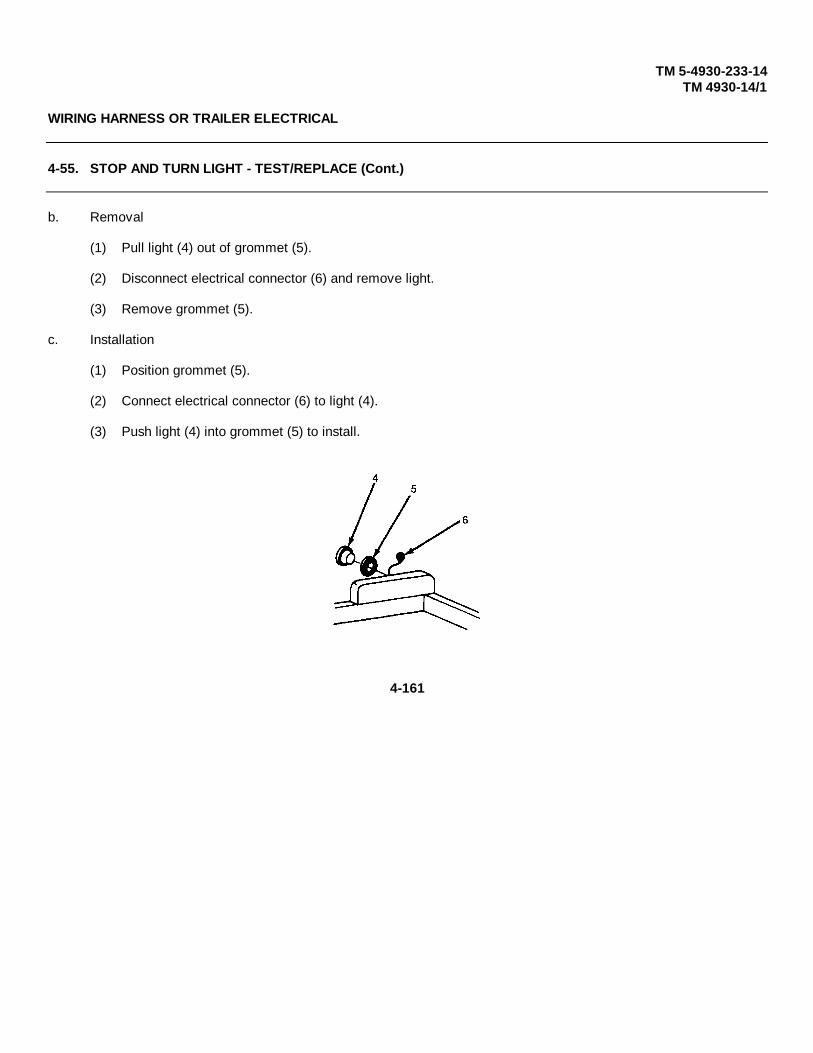
TM 5-4930-233-14TM 4930-14/1
WIRING HARNESS OR TRAILER ELECTRICAL
4-55. STOP AND TURN LIGHT - TEST/REPLACE (Cont.)
b. Removal
(1) Pull light (4) out of grommet (5).
(2) Disconnect electrical connector (6) and remove light.
(3) Remove grommet (5).
c. Installation
(1) Position grommet (5).
(2) Connect electrical connector (6) to light (4).
(3) Push light (4) into grommet (5) to install.
4-161

TM 5-4930-233-14TM 4930-14/1
WIRING HARNESS OR TRAILER ELECTRICAL
4-55. WIRING HARNESS - TEST/REPLACE/REPAIR
This task covers:
a. Test b. Removal c. Repair d. Installation
INITIAL SET-UP:
General Safety Instructions ToolsGeneral Mechanics Tool Box(Section III, Item 1, App B)
WARNING Multimeter(Section III, Item 4, App B)
When working on electrical compo-nents remove all jewelry, dogtags,and metal items to avoid electricalshock and burns.
a. Test
See wiring diagram and wire list (Table 4-7). Perform continuity tests on individual wires. Replace or repair wires with no continuity.
4-162

TM 5-4930-233-14TM 4930-14/1
WIRING HARNESS OR TRAILER ELECTRICAL
4-55. WIRING HARNESS - TEST/REPLACE/REPAIR - (Cont. )
Table 4-7. WIRE LIST
NOTE
All wires are AWG 14 gauge.
b. Removal
Tag and disconnect individual wires and connectors in accordance with the wiring diagram.
Change 1 4-163
TM 5-4930-233-14TM 4930-14/1
WIRING HARNESS OR TRAILER ELECTRICAL
4-56. WIRING HARNESS - TEST/REPLACE/REPAIR - (Cont.)
c. Repair
(1) Replace any wires or connectors that are defective or show signs of wear or damage.
(2) See paragraph 4-10 for general wire repair instructions.
(3) See Table 4-7 Wire List for wire lengths and terminal information when individual wires are re-placed.
d. Installation
See wiring diagram and tags and connect the wire leads and connectors. Remove tags.
4-164

TM 5-4930-233-14TM 4930-14/1
AXLE ASSEMBLY
4-57. WHEEL AND TIRE ASSEMBLY - TEST/REPLACE/REPAIR
This task covers:
a. Removal b. Repair c. Installation
INITIAL SET-UP:
References Special Environmental ConditionsTM 9-2610-200-24 Care Trailer on dry, level groundMaintenance and Repairof Pneumatic Tires and NOTEInner Tubes.
The following procedure appliesto either wheel or tire
ToolsGeneral Mechanics Tool Box(Section III, Item 1, App B) MaterialsJack and Lug Wrench Cloth (Item 2, App E)(Section III, Items 2 & 3, App C)
a. Removal
(1) Securely block trailer at opposite side wheel.
(2) Loosen eight lug nuts (1).
(3) Place jack under the trailer axle and raise tire (2) off of ground.
(4) Remove eight nuts (1), tire and wheel (2).
4-165

TM 5-4930-233-14TM 4930-14/1
AXLE ASSEMBLY
4-57. WHEEL AND TIRE ASSEMBLY - TEST/REPLACE/REPAIR
NOTE
Remove the spare tire from its stowage location as follows and install if it isnecessary to place the trailer back into immediate operation.
(5) Remove cotter pin (7), nut (3), washer (4), retaining plate (5), spare tire and wheel (6).
4-166

TM 5-4930-233-14TM 4930-14/1
AXLE ASSEMBLY
4-57. WHEEL AND TIRE ASSEMBLY - REPLACE/REPAIR - (Cont.)
b. Repair
(1) To demount tire, refer to TM 9-2610-200-24.
(2) Remove all buildup of dirt, grease, etc. by wiping with a soft cloth.
(3) Inspect wheel for cracks, dents, holes, and warps or deformed lug bolt holes. Replace if damaged.
(4) Inspect tire for cracks, holes, signs of chunking, uneven wear or deterioration. Tires are to be repaired inaccordance with TM 9-2610-200-24.
(5) Mount tire in accordance with TM 9-2610-200-24.
4-167
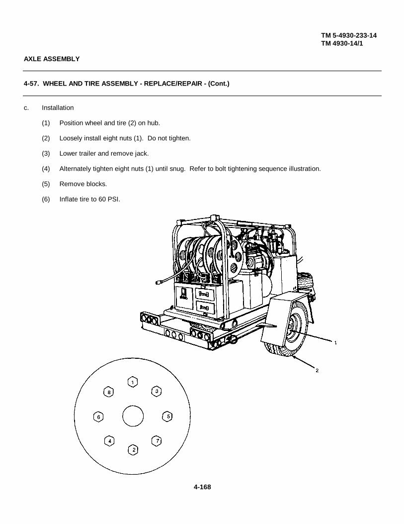
TM 5-4930-233-14TM 4930-14/1
AXLE ASSEMBLY
4-57. WHEEL AND TIRE ASSEMBLY - REPLACE/REPAIR - (Cont.)
c. Installation
(1) Position wheel and tire (2) on hub.
(2) Loosely install eight nuts (1). Do not tighten.
(3) Lower trailer and remove jack.
(4) Alternately tighten eight nuts (1) until snug. Refer to bolt tightening sequence illustration.
(5) Remove blocks.
(6) Inflate tire to 60 PSI.
4-168

TM 5-4930-233-14TM 4930-14/1
AXLE ASSEMBLY
4-58. BRAKE ASSEMBLY - INSPECT/ADJUST/BLEED/REPLACE/REPAIR
This task covers:
a. Inspection b. Adjustment c. Bleeding d. Removale. Disassembly f. Repair g. Assembly
INITIAL SET-UP:Special Environmental Conditions Equipment Condition ReferencesParked on level dry ground Air brake lines connected TM 9-214 Care and
to towing vehicle (para. 2-5) Maintenance of Anti-Tire and Wheel Removal (para 4-57) friction Bearings
NOTEThe service brake can be removed fromthe vehicle or disassembled while in place.This procedure applies to eitherthe right or left brake assembly.
Materials ToolsCloth (Item 22, App E) General Mechanics Tool BoxDrycleaning Solvent (Item 6, App E) (Section III, Item 1, App B)GAA Grease (Item 8 App E) Adjusting Tool, Brake ShoesWire Brush (Item 25 App E) (Section III, Item 8, App B)
a. Inspection
(1) Block opposite side trailer wheel.
(2) Place jack under axle and raise wheel to be inspected.
(3) Spin wheel and apply brakes using air supply valve.
(4) If brakes grind or squeak severely, notify Direct Support Maintenance.
(5) If brakes do not apply properly, adjust (para. 4-58b). If the problem cannot be solved through adjustment,notify Direct Support Maintenance.
(6) Repeat for opposite side brake.
4-169
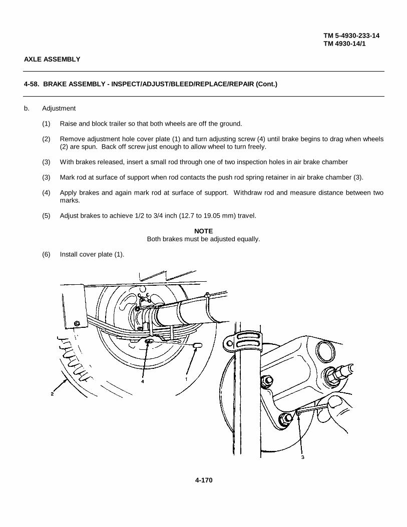
TM 5-4930-233-14TM 4930-14/1
AXLE ASSEMBLY
4-58. BRAKE ASSEMBLY - INSPECT/ADJUST/BLEED/REPLACE/REPAIR (Cont.)
b. Adjustment
(1) Raise and block trailer so that both wheels are off the ground.
(2) Remove adjustment hole cover plate (1) and turn adjusting screw (4) until brake begins to drag when wheels(2) are spun. Back off screw just enough to allow wheel to turn freely.
(3) With brakes released, insert a small rod through one of two inspection holes in air brake chamber
(3) Mark rod at surface of support when rod contacts the push rod spring retainer in air brake chamber (3).
(4) Apply brakes and again mark rod at surface of support. Withdraw rod and measure distance between twomarks.
(5) Adjust brakes to achieve 1/2 to 3/4 inch (12.7 to 19.05 mm) travel.
NOTEBoth brakes must be adjusted equally.
(6) Install cover plate (1).
4-170
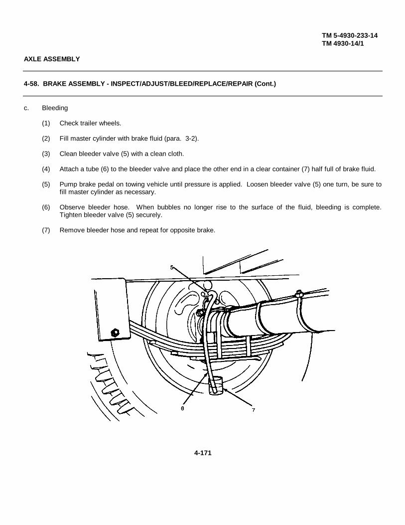
TM 5-4930-233-14TM 4930-14/1
AXLE ASSEMBLY
4-58. BRAKE ASSEMBLY - INSPECT/ADJUST/BLEED/REPLACE/REPAIR (Cont.)
c. Bleeding
(1) Check trailer wheels.
(2) Fill master cylinder with brake fluid (para. 3-2).
(3) Clean bleeder valve (5) with a clean cloth.
(4) Attach a tube (6) to the bleeder valve and place the other end in a clear container (7) half full of brake fluid.
(5) Pump brake pedal on towing vehicle until pressure is applied. Loosen bleeder valve (5) one turn, be sure tofill master cylinder as necessary.
(6) Observe bleeder hose. When bubbles no longer rise to the surface of the fluid, bleeding is complete.Tighten bleeder valve (5) securely.
(7) Remove bleeder hose and repeat for opposite brake.
4-171
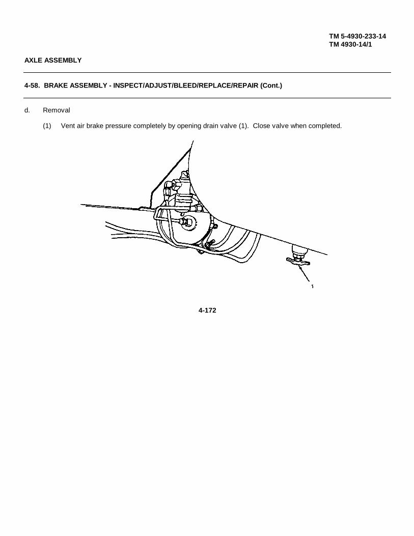
TM 5-4930-233-14TM 4930-14/1
AXLE ASSEMBLY
4-58. BRAKE ASSEMBLY - INSPECT/ADJUST/BLEED/REPLACE/REPAIR (Cont.)
d. Removal
(1) Vent air brake pressure completely by opening drain valve (1). Close valve when completed.
4-172
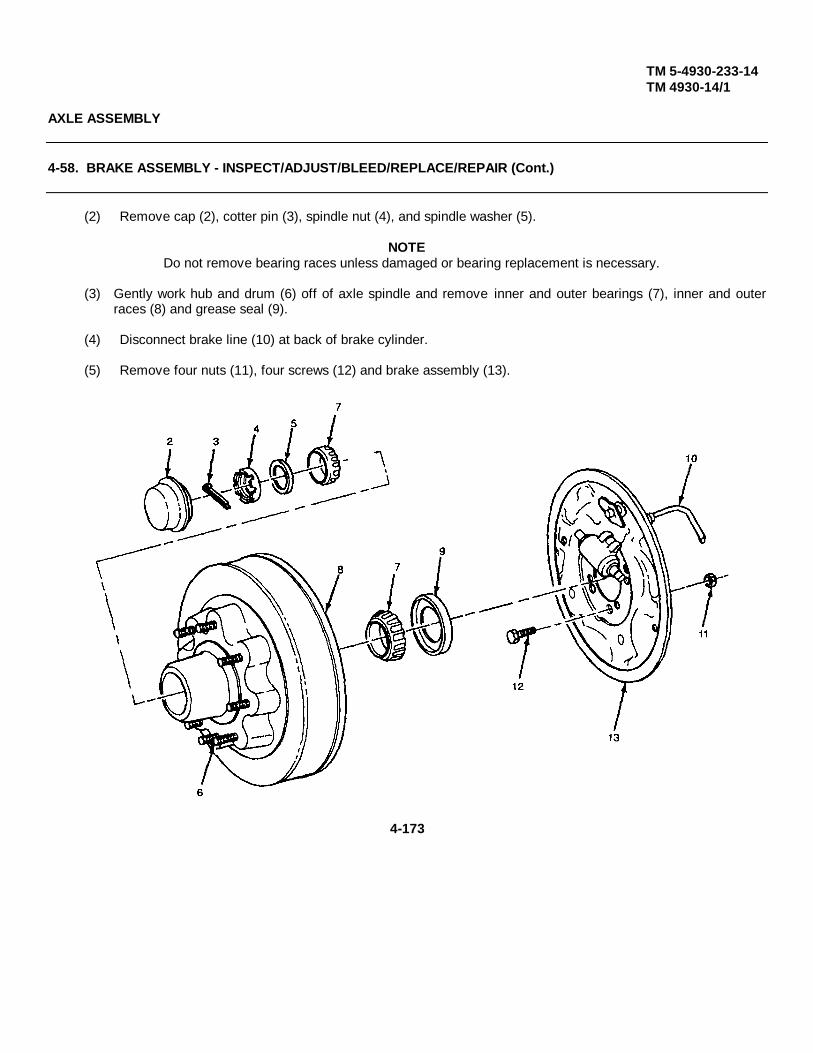
TM 5-4930-233-14TM 4930-14/1
AXLE ASSEMBLY
4-58. BRAKE ASSEMBLY - INSPECT/ADJUST/BLEED/REPLACE/REPAIR (Cont.)
(2) Remove cap (2), cotter pin (3), spindle nut (4), and spindle washer (5).
NOTEDo not remove bearing races unless damaged or bearing replacement is necessary.
(3) Gently work hub and drum (6) off of axle spindle and remove inner and outer bearings (7), inner and outerraces (8) and grease seal (9).
(4) Disconnect brake line (10) at back of brake cylinder.
(5) Remove four nuts (11), four screws (12) and brake assembly (13).
4-173

TM 5-4930-233-14TM 4930-14/1
AXLE ASSEMBLY
4-58. BRAKE ASSEMBLY - INSPECT/ADJUST/BLEED/REPLACE/REPAIR (Cont.)
e. Disassembly
(1) Remove two shoe springs (14) and plate (15).
(2) Remove spring (16) and adjusting screw (17). Remove socket (18) from screw.
(3) Push in two cups (19) and turn to release. Remove four cups (19), two springs (20), two pins (21) and twoshoes (22).
(4) Remove two screws (23), two starwashers (24) and cylinder (25) from back plate (26).
(5) Remove push rod (27) from cylinder.
4-174
TM 5-4930-233-14TM 4930-14/1
AXLE ASSEMBLY
4-58. BRAKE ASSEMBLY - INSPECT/ADJUST/BLEED/REPLACE/REPAIR (Cont.)
f. Repair
WARNING
Clean all parts in a well ventilated area. Avoid inhaling solvent fumes and prolonged exposure ofthe skin to cleaning solvent. Failure to do so can cause severe injury or death. Do not use nearflame or excessive heat. Flash point of solvent is 100°F to 138°F (38°C to 59°C).
(1) Clean all parts of grease and dirt using dry cleaning solvent.
(2) Use a wire brush to remove all corrosion.
(3) Inspect back plate for cracks, galling or wear. Replace if defective.
(4) Inspect hydraulic cylinder for leakage or corrosion. Replace if defective.
(5) Measure brake linings. If thickness is not 1/8 inch (3.175 mm), replace. If linings are cracked, replace.
(6) Replace adjustment screw if corroded or worn.
(7) Inspect bearings in accordance with TM 9-214.
(8) Discard springs (20) and cups (19).
4-175
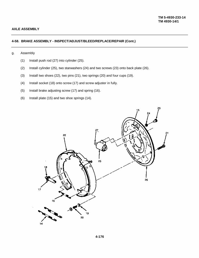
TM 5-4930-233-14TM 4930-14/1
AXLE ASSEMBLY
4-58. BRAKE ASSEMBLY - INSPECT/ADJUST/BLEED/REPLACE/REPAIR (Cont.)
g. Assembly
(1) Install push rod (27) into cylinder (25).
(2) Install cylinder (25), two starwashers (24) and two screws (23) onto back plate (26).
(3) Install two shoes (22), two pins (21), two springs (20) and four cups (19).
(4) Install socket (18) onto screw (17) and screw adjuster in fully.
(5) Install brake adjusting screw (17) and spring (16).
(6) Install plate (15) and two shoe springs (14).
4-176
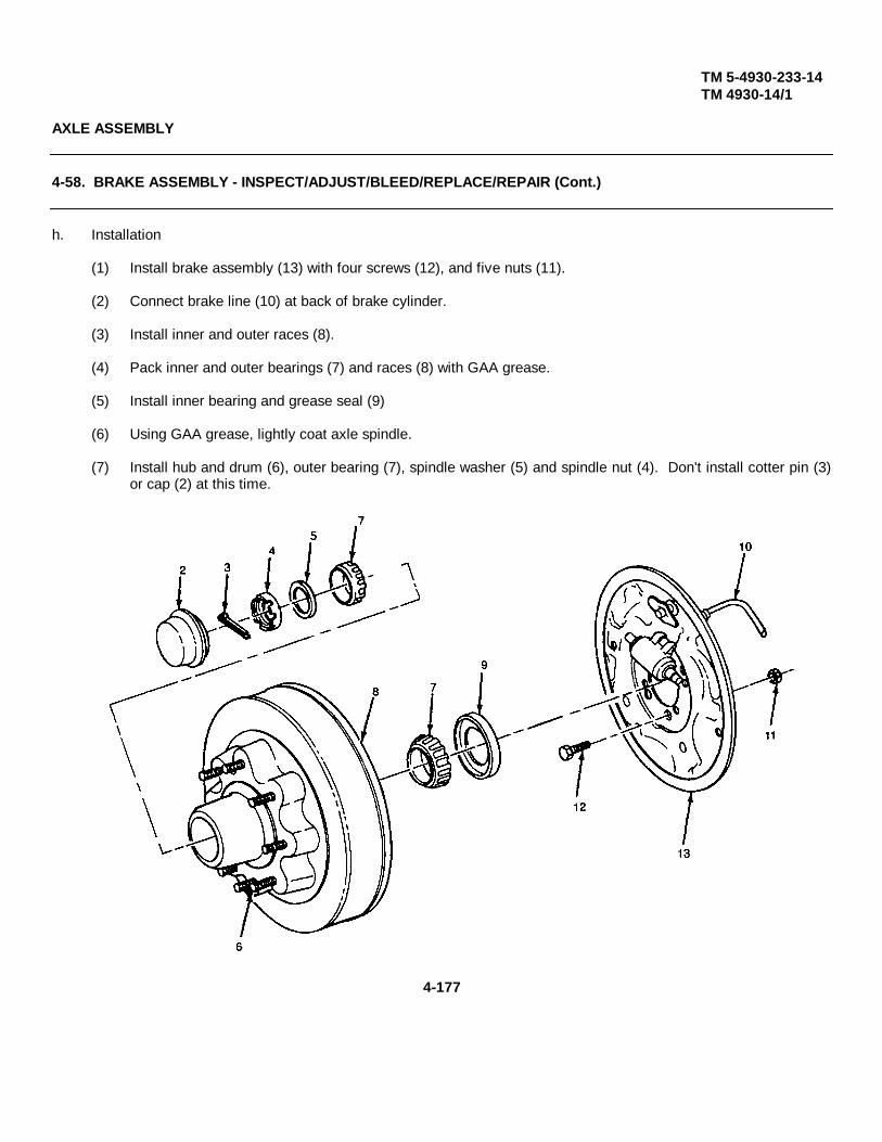
TM 5-4930-233-14TM 4930-14/1
AXLE ASSEMBLY
4-58. BRAKE ASSEMBLY - INSPECT/ADJUST/BLEED/REPLACE/REPAIR (Cont.)
h. Installation
(1) Install brake assembly (13) with four screws (12), and five nuts (11).
(2) Connect brake line (10) at back of brake cylinder.
(3) Install inner and outer races (8).
(4) Pack inner and outer bearings (7) and races (8) with GAA grease.
(5) Install inner bearing and grease seal (9)
(6) Using GAA grease, lightly coat axle spindle.
(7) Install hub and drum (6), outer bearing (7), spindle washer (5) and spindle nut (4). Don't install cotter pin (3)or cap (2) at this time.
4-177
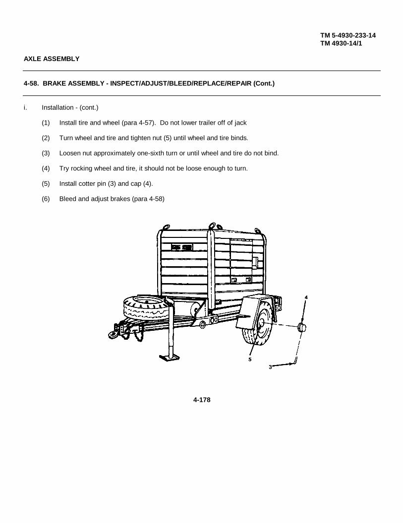
TM 5-4930-233-14TM 4930-14/1
AXLE ASSEMBLY
4-58. BRAKE ASSEMBLY - INSPECT/ADJUST/BLEED/REPLACE/REPAIR (Cont.)
i. Installation - (cont.)
(1) Install tire and wheel (para 4-57). Do not lower trailer off of jack
(2) Turn wheel and tire and tighten nut (5) until wheel and tire binds.
(3) Loosen nut approximately one-sixth turn or until wheel and tire do not bind.
(4) Try rocking wheel and tire, it should not be loose enough to turn.
(5) Install cotter pin (3) and cap (4).
(6) Bleed and adjust brakes (para 4-58)
4-178

TM 5-4930-233-14TM 4930-14/1
TRAILER ASSEMBLY
4-59. JACK LEG ASSEMBLY - REPLACE
This task covers:
a. Removal b. Installation
INITIAL SET-UP:Tools
General Mechanics Tool Box (Section III, Item 1, App B)
a. RemovalNOTE
Step 1 applies to removal of front jack leg. Go to step 2 for removal of rear jacks.
(1) Remove retaining pin (1), pin (2) and Jack leg (3).
NOTE.The following instructions apply to either of the two rear jacks.
(2) Fully retract rear jack (4).
(3) Raise rear of trailer using external jack to allow removal of rear jack.
(4) Remove retaining pin (5), pin (6) and slide rear jack (4) out of trailer frame.
4-179

TM 5-4930-233-14TM 4930-14/1
TRAILER ASSEMBLY
4-59. JACK LEG ASSEMBLY - REPLACE (Cont.)
b. Installation
NOTE• Go to step 3 for installation of front jack leg.• Steps 1 through 2 apply to either of the two rear jacks.
(1) Slide rear jack (4) into position and install pin (6) and retaining pin (5).
(2) Lower trailer and remove external jack.
(3) Install front jack leg (3), pin (2) and retaining pin (1)
4-180

TM 5-4930-233-14TM 4930-14/1
Section VI. PREPARATION FOR STORAGE OR SHIPMENT
4-60. PRESERVATION
This task covers:
a. Preparation b. Preservation
INITIAL SET-UP:Materials/Parts References
Detergent (Item 5, AppE) TM 43-0139 PaintingSheets, plastics, block instructions for field use.(Item 15, AppE)Tape, masking (Item17, AppE) Equipment Condition
Enclosure Removed (para 4-11)Tools
General Mechanics Tool Box(Section III, Item 1, AppB)
a. Preparation
(1) Clean trailer and skid using soap and water solution. Dry completely.
(2) Using wire brush, remove any corrosion and touch up paint (TM 43-0139).
b. Preservation
(1) Apply preservation to the following areas:
a Interior of enclosure assembly (1).
b Entire skid and trailer bottom (2).
c Fender wells (3).
d Interiors of reel cabinet (4), tool box (5) and lube tank (6) (not in lube reservoirs).
e All open areas and areas where moisture is likely to collect.
(2) Using black plastic sheets and masking tape cover two wheels (7).
4-181
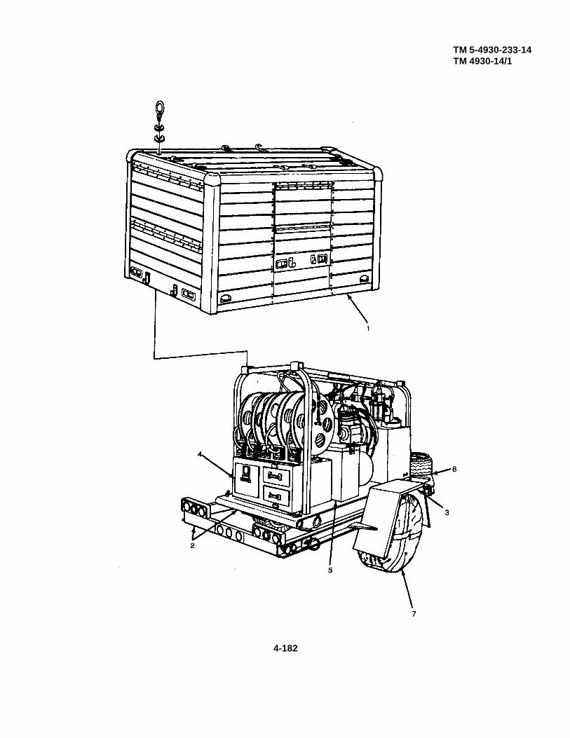
TM 5-4930-233-14TM 4930-14/1
4-182
TM 5-4930-233-14TM 4930-14/1
PREPARATION FOR STORAGE OR SHIPMENT
4-61. PACKING, SHIPMENT AND STORAGE
This task covers:
a. Overview b. Storage c. Shipment
INITIAL SET-UP:Tools
General Mechanics Tool Box (Section III, item 1, AppB)
a. OverviewThe unit commander is to make sure that the lube and service units and auxiliary equipment in his or her commandare properly cared for.
A unit may not be able to care for the trailer properly because it lacks:
(1) Time
(2) Trained personnel
(3) Proper tools
If any or all of the above conditions exist, the unit commander, with the approval of the major commander, may:
(4) Place the trailer in administrative storage.
(5) Return the trailer to supply.
When preparing the trailer for administrative storage, the unit commander must make sure that the trailer and the auxiliary equipment are properly stored. To do this the trailer and the auxiliary equipment must be protected from:
(6) Corrosion
(7) Deterioration
(8) Physical damage
Item should be in mission readiness within 24 hours or within the time factors as determined by the directingauthority.
4-183

TM 5-4930-233-14TM 4930-14/1
PREPARATION FOR STORAGE OR SHIPMENT
4-61. PACKING, SHIPMENT AND STORAGE - (Cont.)
Time limitations. You may place the trailer and its auxiliary equipment in administrative storage for 90 days. After that, the trailer and its auxiliary equipment must be cleaned and preserved as described in the following storage procedure.
b. Storage
(1) Do semiannual PMCS (para. 4-6).
(2) Lubricate entire system (para. 3-2).
(3) Preserve (para. 4-60).
(4) Locate trailer on level ground in an area which affords protection from the elements and pilferage. Thislocation should give easy access to the unit to allow inspection and service as required.
(5) Block trailer so that the wheels are off the ground.
(6) Tie a tag to the trailer with the words ADMINISTRATIVE STORAGE written on it. The trailer may not beoperated when the tag is tied to it.
c. ShipmentTrailers shipped on flatcars require wheel blocking in accordance with the Association of American Railroads RulesGoverning the Loading of Commodities on Open-Top Cars". Chocks for blocking the trailer wheels and anchors fortie-downs may be manufactured in accordance with the drawings in the appendix.
4-184

TM 5-4930-233-14TM 4930-14/1
PREPARATION FOR STORAGE OR SHIPMENT
4-62. INSPECTION IN ADMINISTRATIVE STORAGE
This task covers:
a. Overview b. Inspection
INITIAL SET-UP:
References Tools
TM 43-0139 Painting General Mechanics Tool BoxInstructions for field use (Section III, Item 1, AppB)
a. Overview
Inspect the trailer:
(1) Once each month.
(2) Just after hard rain, heavy snow storm, or other bad weather conditions.
b. Inspection
(1) Inspect lube and service unit for corrosion and damage.
(2) Remove corrosion and touch up paint.
(3) Repair any damage.
(4) Inspect for evidence of standing water. If necessary preserve these areas (para. 4-60).
4-185/(4-186 blank)

TM 10-4930-233-14TM 4930-14/1
Chapter 5
DIRECT SUPPORT MAINTENANCE INSTRUCTIONS
Section I. DIRECT SUPPORT TROUBLESHOOTING
5-1. GENERAL
a. This section provides information useful in diagnosing and correcting unsatisfactory operation or failure ofthe Lube and Service Unit. Each malfunction is followed by a list of probable causes and actions to take toremedy the malfunction. You should perform the tests/inspections and corrective actions in the order listed.
b. This manual cannot list all malfunctions that may occur; nor all tests or inspections and corrective actions. Ifa malfunction is not listed or is not corrected by listed corrective actions, notify your supervisor.
I
Change 1 5-1
TM 10-4930-233-14TM 4930-14/1
Table 5-1. Direct Support Troubleshooting
ITEMMALFUNCTION
TEST OR INSPECTIONCORRECTIVE ACTION
TRANSFER PUMP1. LEAKING FROM BUSHING ASSEMBLY ADJUSTMENT HOLE
Check teflon packing for improper adjustment or wear.Adjust or replace teflon packing set as required (paragraph 5-5).
2. PUMP DOES NOT OPERATEStep 1. Check for clogged air inlet.
Clean or replace air coupler, adapters and shut off valve (paragraph 5-5).Step 2. Check teflon packing set for improper adjustment.
Adjust teflon packing set as required (paragraph 5-5).
3. PUMP OPERATES BUT DELIVERS LITTLE OR NO LUBRICANTCheck for worn packings in power head and/or pump tube assembly.
Replace worn packings or seals (paragraph 5-5).
GEAR LUBE DISPENSERS
1. LUBRICANT LEAKS FROM AROUND INLETCheck washers and block "V" packing at inlet for wear.
Replace washers and block “V" packing (paragraph 5-7).
2. LUBRICANT FLOWS OUT OF NOZZLE CONTINUOUSLYCheck valve assembly and seat at lever assembly for wear.
Replace valve assembly and seat (paragraph 5-7).
3. LEAKAGE OCCURS FROM LEVER ASSEMBLYCheck preformed packings at lever assembly for wear.
Replace preformed packings (paragraph 5-7)
5-2

TM 5-4930-233-14TM 4930-14/1
Table 5-1. Direct Support Troubleshooting - Continued
ITEMMALFUNCTION
TEST OR INSPECTIONCORRECTIVE ACTION
4. LEAKAGE OCCURS FROM OUTLET FITTING BODYCheck preformed packings at outlet fitting body for wear.
Replace preformed packings (paragraph 5-7).
5. LEAKAGE OCCURS AROUND FACE DIALCheck packing and leather washer for wear at gear and shaft.
Replace packing and leather washer (paragraph 5-7).
ENGINE OIL DISPENSER
1. LUBRICANT LEAKS FROM AROUND INLETCheck preformed packings and block "V" packing at inlet for wear.
Replace preformed packings and block "V" packing (paragraph 5-8).
2. LUBRICANT FLOWS OUT OF NOZZLE CONTINUOUSLYCheck valve assembly and seat at lever assembly for wear.
Replace valve assembly and seat (paragraph 5-8).
3. LEAKAGE OCCURS FROM LEVER ASSEMBLYCheck preformed packings at lever assembly for wear.
Replace preformed packings (paragraph 5-8).
4. LEAKAGE OCCURS FROM OUTLET FITTING BODYCheck preformed packings at outlet fitting body for wear.
Replace preformed packings (paragraph 5-8).
5. LEAKAGE OCCURS AROUND FACE DIALInspect packing and leather washer for wear at gear and shaft.
Replace packing and leather washer (paragraph 5-8).
5-3

TM 5-4930-233-14TM 4930-14/1
Table 5-1. Direct Support Troubleshooting - Continued
ITEMMALFUNCTION
TEST OR INSPECTIONCORRECTIVE ACTION
GREASE CONTROL VALVE
1. LUBRICANT LEAKS OUT OF GREASE COUPLING WHEN VALVE IS NOT IN USEStep 1. Check control valve for proper adjustment.
Adjust control valve (paragraph 5-9).
Step 2. Check spring, plunger, and seat assembly for wear.Replace spring, plunger, and seat assembly if worn (paragraph 5-9).
2. LUBRICANT LEAKS OUT OF TOP OF GREASE CONTROL VALVECheck preformed packings in packing plug for wear.
Replace preformed packings (paragraph 5-9).
3. LUBRICANT LEAKS OUT OF BOTTOM OF GREASE CONTROL VALVESStep 1. Check bushing and locknut at inlet for looseness.
Tighten bushing and locknut.
Step 2. Check packing ring in stem of control valve for wear.Replace packing ring (paragraph 5-9).
4. GREASE CONTROL VALVE HAS NO "ONE SHOT" CAPABILITIESStep 1. Check control valve for correct adjustment.
Adjust control valve (paragraph 5-9).
Step 2. Inspect spring, plunger, and seat assembly for wear.Replace spring, plunger, and seat assembly if worn (paragraph 5-9).
5. GREASE CONTROL VALVE FAILS TO DELIVER GREASE WHEN TRIGGER IS OPERATEDCheck control valve for proper adjustment
Adjust control valve (paragraph 5-9).
5-4

TM 5-4930-233-14TM 4930-14/1
Table 5-1. Direct Support Troubleshooting - Continued
ITEMMALFUNCTION
TEST OR INSPECTIONCORRECTIVE ACTION
LOW PRESSURE PUMP
1. LOW PRESSURE PUMP DOES NOT PUMP CORRECTLY
Step 1. Inspect for foreign objects lodged in check valve or seat of pump tube.Remove foreign objects and replace defective parts as needed (paragraph 5-18).
Step 2. Check for worn piston packings in pump tube body and/or cylinder.Replace packings as required (paragraph 5-18).
Step 3. Inspect for damaged or bent shafts or cylinders.Replace damaged parts (paragraph 5-18).
2. LOW PRESSURE PUMP LEAKS LUBRICANT FROM CYLINDER HEAD BODYCheck pump tube gaskets and/or packings for wear
Replace worn gaskets and packings in pump tube assembly (paragraph 5-18).
HIGH PRESSURE PUMP
1. HIGH PRESSURE PUMP DOES NOT PUMP CORRECTLY
Step 1. Check for foreign objects lodged in check valve or seat of pump tube.Remove foreign objects and replace defective parts as needed (paragraph 5-19).
Step 2. Check for worn piston packings in pump tube body and/or cylinder.Replace packings as required (paragraph 5-19).
Step 3. Inspect for damaged or bent shafts and cylinder.Replace damaged parts (paragraph 5-19).
5-5

TM 5-4930-233-14TM 4930-14/1
Table 5-1. Direct Support Troubleshooting - Continued
ITEMMALFUNCTION
TEST OR INSPECTIONCORRECTIVE ACTION
2. HIGH PRESSURE PUMP LEAKS LUBRICANT FROM CYLINDER HEAD BODYCheck pump tube gaskets and/or packings for wear.
Replace worn gaskets and packings in pump tube assembly (paragraph 5-19)
AIR REGULATOR
AIR REGULATOR OPERATES ERRATICALLY OR WILL NOT REGULATEInspect valve for dirt.
Disassemble and clean regulator (paragraph 5-17).
AIR COMPRESSOR
1. COMPRESSOR PUMPS SLOWLY OR HAS INSUFFICIENT PRESSUREStep 1. Check compressor head valves for leaks.
Clean or replace valves and valve components as needed (paragraph 5-15).
Step 2. Check for clogged or damaged head unloader valves.Clean or replace unloader valves (paragraph 5-15).
2. COMPRESSOR USES EXCESSIVE AMOUNTS OF OILInspect for worn or damaged piston oil rings.
Replace oil rings (paragraph 5-14).
3. COMPRESSOR MAKES EXCESSIVE NOISE WHEN OPERATING
Step 1. Inspect loose external parts.Tighten any loose part found during inspection.
Step 2. Check for foreign matter such as carbon, metal chips, etc. on piston.Remove head (paragraph 5-14) and clean.
5-6

TM 5-4930-233-14TM 4930-14/1
Table 5-1. Direct Support Troubleshooting - Continued
ITEMMALFUNCTION
TEST OR INSPECTIONCORRECTIVE ACTION
Step 3. Check crankshaft for excessive end play.Remove one end cover gasket (paragraph 5-14).
Step 4. Check torque on head valve hold down cover screws.Tighten hold down cover screws to correct torque (paragraph 5-15).
Step 5. Inspect for loose or worn internal parts.Replace and tighten internal parts as necessary (paragraph 5-14).
4. COMPRESSOR OVERHEATS
Step 1. Inspect for properly seated head valves.Disassemble head and seat valves correctly (paragraph 5-15).
Step 2. Check for blown cylinder head gasket.Replace cylinder head gasket (paragraph 5-14).
AXLE ASSEMBLY
1. TRAILER TIRES WEAR UNEVENLY
Step 1. Check wheel bearing adjustment.Adjust wheel bearings (paragraph 5-25).
Step 2. Inspect axle tube for bends.Remove (paragraph 5-24) and straighten axle.
2. WHEEL HUB RUNS EXCESSIVELY HOTCheck wheel bearings for adequate lubrication.
Remove and pack wheel bearings.
5-7
TM 5-4930-233-14TM 4930-14/1
Table 5-1. Direct Support Troubleshooting - Continued
ITEMMALFUNCTION
TEST OR INSPECTIONCORRECTIVE ACTION
BRAKE ASSEMBLY
1. SERVICE BRAKES WILL NOT APPLY
Step 1. Check for damaged or worn wheel brake cylinder.Replace wheel brake cylinder (paragraph 5-25).
Step 2. Inspect for grease on brake linings.Repair leaks and brake shoes (paragraph 5-25).
Step 3. Inspect brake linings for wear.Replace brake shoes (paragraph 5-25).
Step 4. Check for scored brake drum.Replace brake drum (paragraph 5-25).
2. BRAKES APPLY AND RELEASE SLOWLY
Inspect for weak or broken brake return springs.Replace brake return springs (paragraph 5-25).
3. BRAKES GRAB
Step 1. Inspect wheel bearings for proper adjustment and/or wear.Adjust or replace as needed (paragraph 5-25).
Step 2. Check for out of round, cracked, or deformed brake drum.Replace brake drum (paragraph 5-25).
Step 3. Inspect for loose or worn brake linings.Replace brake linings (paragraph 5-25).
5-8
TM 5-4930-233-14TM 4930-14/1
Section II. MAINTENANCE PROCEDURES
ENCLOSURE AND SKID ASSEMBLY
5-2. ENCLOSURE AND SKID ASSEMBLY - REPLACE
This task covers:
a. Removal b. Installation
INITIAL SET-UP:
Tools Special Environmental ConditionsGeneral Mechanics Tool Box Trailer parked on level ground(Section III, Item 1, App B) and blocked.Hoist
a. Removal
(1) Attach hoist at four lifting eyes (1).
(2) Remove six nuts (2), six washers (3), six screws (4) and six beveled washers (5).
(3) Lift skid sub assembly (6) off of trailer assembly (7) and place on firm, level ground.
b. Installation
(1) Attach hoist at four lifting eyes (1).
(2) Lift skid sub assembly (6) onto trailer assembly (7) and install six beveled washers (5), six screws (4), sixlockwashers (3) and six nuts (2).
5-9
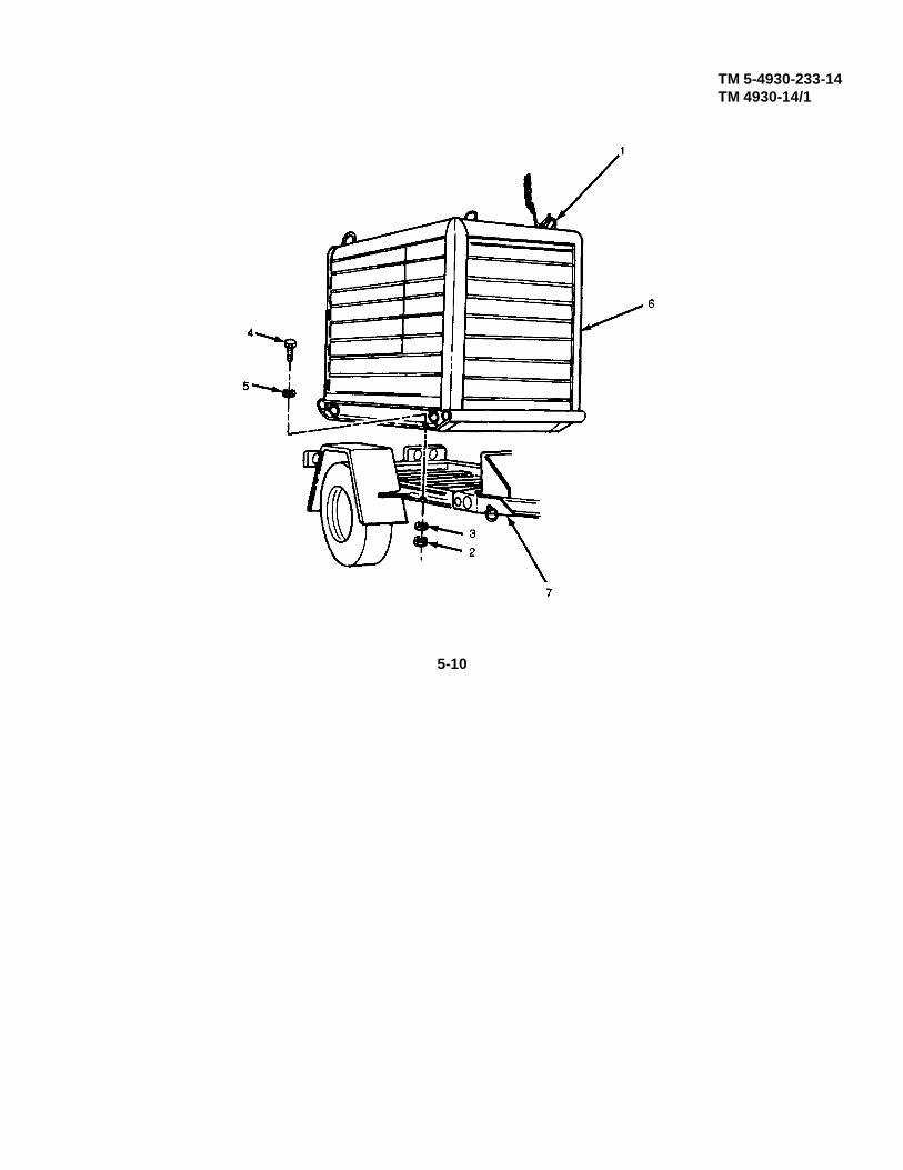
TM 5-4930-233-14TM 4930-14/1
5-10

TM 5-4930-233-14TM 4930-14/1
ENCLOSURE
5-3. DOORS - REPAIR
This task covers:
a. Disassembly b. Repair c. Assembly
INITIAL SET-UP:
Equipment Condition NOTEDoor Removed (para. 4-12) The following procedures apply to
any four door assemblies
ToolsGeneral Mechanics Tool Box(Section III, Item 1, App B)
a. Disassembly
NOTE
Step 1 applies only to front and rear doors.
(1) Drill out ten rivets (1), two tracks (2) and two shutters (3).
(2) Remove two handles (4) and shutters (3).
5-11

TM 5-4930-233-14TM 4930-14/1
ENCLOSURE
5-3. DOORS - REPAIR - (Cont.)
a. Disassembly - (cont.)
(3) Drill out rivets (5) as required and remove two lower latches (6), two upper latches (7), two hooks (8), twohinges (9), upper panel (10) and lower panel (11) from frames (12).
b. Repair
(1) Inspect all sheet metal parts for damage. Straighten if possible, replace if damage is too extensive.
(2) Inspect latches for correct operation. Replace if faulty.
c. Installation
(1) Install lower panel (11), upper panel (10), two hinges (9), two hooks (8), two upper latches (7) and two lowerlatches (6) using rivets (5) as necessary.
NOTEStep (2) and (3) applies only to front and rear doors.
(2) Install two handles (4) and two shutters (3).
(3) Position two shutters (3), two tracks (2) and install using ten rivets (1).
5-12

TM 10-4930-233-14TM 4930-14/1
ENCLOSURE AND SKID ASSEMBLY
5-4. PANELS- REPLACE
This task covers:
a. Removal b. Installation
INITIAL SET-UP:Materials/Parts Equipment Condition Tools
Epoxy-polymide primer Enclosure Assembly Removed Drill with 3/16 Drill Bitscoatings (Item 13 App.E) (para 4-11) (Section III, Item 2, App B)Synthetic rubber caulkingcompound (Item 4, App.E)
a. Removal.
NOTE
Step 2 applies to all panels. For other steps, proceed only as needed.
(1) For top panel removal, drill out all rivets (1) and remove eight hooks (2).
(2) For all panels, drill out rivets (3) around outside edge and remove panel (4).
(3) For front and rear side panels, drill out four rivets (5) and remove handle (6).
(4) For near right side panel, drill out nine rivets (7) and remove storage pocket (8).
Change 1 5-12.1
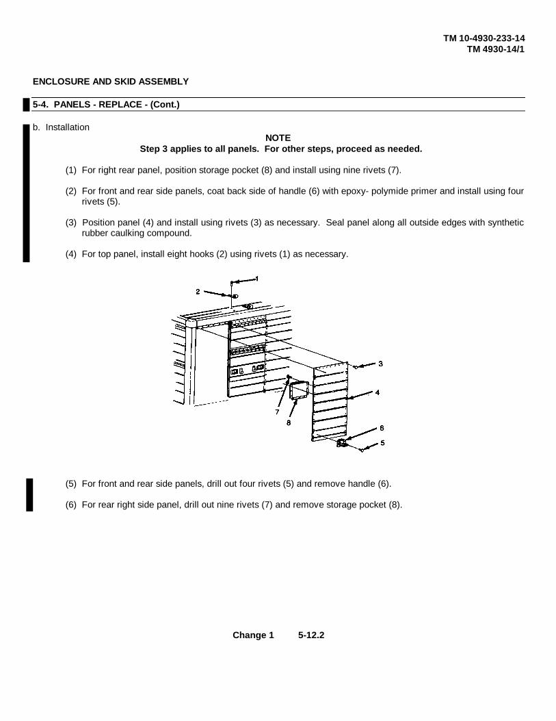
TM 10-4930-233-14TM 4930-14/1
ENCLOSURE AND SKID ASSEMBLY
5-4. PANELS - REPLACE - (Cont.)
b. InstallationNOTE
Step 3 applies to all panels. For other steps, proceed as needed.
(1) For right rear panel, position storage pocket (8) and install using nine rivets (7).
(2) For front and rear side panels, coat back side of handle (6) with epoxy- polymide primer and install using fourrivets (5).
(3) Position panel (4) and install using rivets (3) as necessary. Seal panel along all outside edges with syntheticrubber caulking compound.
(4) For top panel, install eight hooks (2) using rivets (1) as necessary.
(5) For front and rear side panels, drill out four rivets (5) and remove handle (6).
(6) For rear right side panel, drill out nine rivets (7) and remove storage pocket (8).
Change 1 5-12.2

TM 5-4930-233-14TM 4930-14/1
SKID SUB ASSEMBLY
5-5. TRANSFER PUMP - REPAIR/ADJUST
This task covers:
a. Removal b. Disassembly c. Repaird. Assembly e. Adjustment f. Installation
INITIAL SET-UP:
ToolsGeneral Mechanics Tool Box (Section III, Item 1, App B)
a. Removal
NOTE
Remove strap assembly only If damaged.
(1) Remove transfer pump (1) from strap assembly (2).
(2) Remove strap assembly (2) from enclosure (3) if damaged.
Change 1 (5-13 blank)/5-14

TM 5-4930-233-14TM 4930-14/1
SKID SUB ASSEMBLY
5-5. TRANSFER PUMP - REPAIR/ADJUST (Cont.)
b. Disassembly
(1) Remove quick disconnect (4), coupler (5), shutoff valve (6), and adapter (7).
(2) Loosen bung adapter nut (8) and slide bung adapter (9) off of pump.
(3) Loosen jam nut (10) and unscrew cylinder (11) from pump casting (12) to expose cotter pin (13).
(4) Remove cotter pin (13) and unscrew pump tube rod (14) from power head piston (15).
(5) Remove gasket (16).
5-15

TM 5-4930-233-14TM 4930-14/1
SKID SUB ASSEMBLY
5-5. TRANSFER PUMP - REPAIR/ADJUST (Cont.)
b. Disassembly - (cont.)
WARNING
Do not remove cylinder completely with a wrench. If cylinder cannot be easily unscrewed by handafter it has been loosened, pressure is probably trapped inside. Venting pressure before removalis necessary because a pressurized cylinder can fly off with damaging force that can causepersonal injury.
(6) Loosen cylinder (17).
(7) After cylinder is loosened, remove it by hand. Do not force.
WARNING
Protective goggles must be worn when drilling cylinder to prevent personnel injury caused bymetal shavings flying out under pressure.
(8) If cylinder (17) does not easily unscrew, relieve pressure by drilling a small hole in the center to vent-pressure.
(9) Remove cylinder (17) and preformed packing (18). Discard cylinder if it was drilled.
(10) Withdraw piston assembly (15).
(11) Remove rubber seal (19), backup washer (20), metal gasket (25), adapter (21) and preformed packing (22).
(12) Remove bushing (23) and teflon packing set (24) from pump casting (12).
5-16

TM 5-4930-233-14TM 4930-14/1
SKID SUB ASSEMBLY
5-5. TRANSFER PUMP - REPAIR/ADJUST (Cont.)
(13) To disassemble piston assembly (15) remove three elastic nuts (26), seal plate (27) and three spacers (28).
(14) Remove three screws (29) and three gaskets (30).
(15) Remove adapter (31), thick washer (32), packing (33), thin washer (34), washer (35), spring (36), spacer(37), solid washer (38), and washer (39), from piston (40).
5-17

TM 5-4930-233-14TM 4930-14/1
SKID SUB ASSEMBLY
5-5. TRANSFER PUMP - REPAIR/ADJUST (Cont.)
b. Disassembly - (cont)
(16) To disassemble pump tube (41) remove valve base (42) and preformed packing (43).
(17) Remove selflocking nut (44), screw (45) and washer (46).
(18) Take rod and stop assembly (47) out of cylinder (48).
(19) Remove nut (49), plunger (50) and washer (51) from pump tube rod (14).
5-18

TM 5-4930-233-14TM 4930-14/1
SKID SUB ASSEMBLY
5-5. TRANSFER PUMP - REPAIR/ADJUST (Cont.)
c. Repair
(1) Clean all parts thoroughly.
(2) Discard any parts that are included in repair kit (TM 5-4930-233-24P).
(3) Inspect all piston parts and cylinders for wear or scoring. Replace as needed.
(4) Inspect threaded surfaces for damage. Replace if defective.
(5) Inspect castings and cylinders for cracks or deformities. Replace any component that would prevent correctoperation.
d. Assembly
NOTE
Lubricant referred to in the procedures below is included in Repair kits (TM 5-4930-233-24P).
(1) Lubricate all seals, preformed packings and sealing rings.
(2) Install washer (51), plunger (50) and nut (49) onto pump tube rod (14). Be sure that ground surface ofwasher faces plunger.
(3) Slide rod and stop assembly (47) into cylinder (48).
(4) Install perform packing (43), washer (46), screw (45) and selflocking nut (44) onto valve base (42).
(5) Install valve base (42) onto cylinder (48).
(6) Install washer (39), solid washer (38), spacer (37),spring (36), washer (35), thin washer (34), packing (33),thick washer (32) and adapter (31) onto piston (40). Be sure that packing (33) is installed with marking "TopSide" facing up.
(7) Install three gaskets (30) and three screws (29).
(8) Install three spacers (28), seal plate (27) and three elastic nuts (26). Torque nuts to 23-27 in. lbs. (2.599-3.05N.m).
5-19

TM 5-4930-233-14TM 4930-14/1
SKID SUB ASSEMBLY
5-5. TRANSFER PUMP - REPAIR/ADJUST (Cont.)
d. Assembly- (cont.)
(9) Install teflon packing set (24) and bushing (23) into pump casting (12). Do not tighten bushing.
(10) Install preformed packing (22), adapter (21), metal gasket (25), backup washer (20) and rubber seal (19).
(11) Install piston assembly (15) and hand tighten bushing (23).
(12) Install preformed packing (18) and cylinder (17).
5-20

TM 5-4930-233-14TM 4930-14/1
SKID SUB ASSEMBLY
5-5. TRANSFER PUMP - REPAIR/ADJUST (Cont.)
d. Assembly - (cont.)
(13) Connect power head piston (15) and pump tube rod (14).
(14) Install cotter pin (13).
(15) Thread cylinder (11) into pump casting (12) and tighten jam nut (10).
(16) Slide bung adapter (9) onto pump and tighten bung adapter nut (6).
(17) Install adapter (7), shutoff valve (6), coupler (5) and quick disconnect (4).
(18) Perform initial run-in and adjustment (para. 5-5e).
5-21

TM 5-4930-233-14TM 4930-14/1
SKID SUB ASSEMBLY
5-5. TRANSFER PUMP - REPAIR/ADJUST (Cont.)
e. Adjustment
NOTE
This adjustment can also be made to correct leaking that occurs around packing adjustment slot
(1) Run pump for approximately 5 minutes to allow teflon packings to form evenly.
(2) Allow cylinder and plunger to cool.
(3) Apply a maximum of 30 psi air pressure. If pump does not start or if leakage occurs, adjustment is required.
(4) Loosen adapter (21) to a point where its holes line up with a hole on bushing (23).
CAUTION
Do not overtighten bushing as this will cause piston assembly to bind. If pump did not operateduring run-in, skip steps (5) and (6).
(5) Place a rod through holes and hand tighten to drive bushing assembly into pump casting, thereby tighteningpackings.
(6) Remove rod and repeat run-in. If pump doesn't operate proceed. If pump operates without leakage, go tostep (9).
5-22
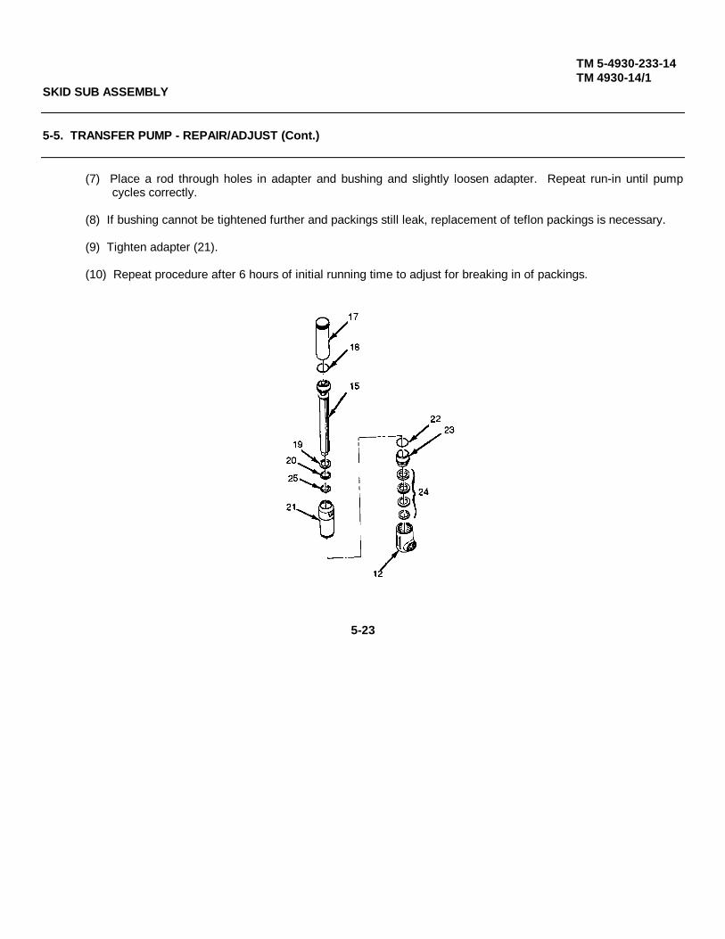
TM 5-4930-233-14TM 4930-14/1
SKID SUB ASSEMBLY
5-5. TRANSFER PUMP - REPAIR/ADJUST (Cont.)
(7) Place a rod through holes in adapter and bushing and slightly loosen adapter. Repeat run-in until pumpcycles correctly.
(8) If bushing cannot be tightened further and packings still leak, replacement of teflon packings is necessary.
(9) Tighten adapter (21).
(10) Repeat procedure after 6 hours of initial running time to adjust for breaking in of packings.
5-23
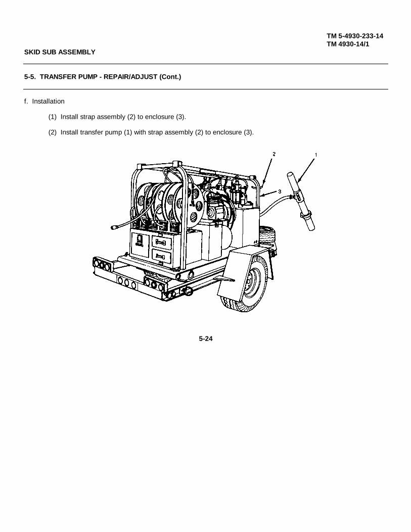
TM 5-4930-233-14TM 4930-14/1
SKID SUB ASSEMBLY
5-5. TRANSFER PUMP - REPAIR/ADJUST (Cont.)
f. Installation
(1) Install strap assembly (2) to enclosure (3).
(2) Install transfer pump (1) with strap assembly (2) to enclosure (3).
5-24

TM 5-4930-233-14TM 4930-14/1
SKID SUB ASSEMBLY
5-6. FUEL TANK ASSEMBLY - REPAIR
This task covers:
a. Disassembly b. Repair c. Assembly
INITIAL SET-UP:
GENERAL SAFETY INTRODUCTIONS Equipment ConditionFuel Tank Removed (para 4-16)
WARNINGTools
Do not use open flame or smoke General Mechanics Tool Boxwhen working on the fuel system. (Section III, Item 1, App B)An explosion may occur, causingsevere injury or death.
a. Disassembly
(1) Remove elbow (1) and shutoff cock (2).
(2) Remove five screws (3), five starwashers (4), sending unit (5) and gasket (6).
(3) Remove engine fuel hose assembly (7), elbow (8), fuel filter (9), elbow (10), nipple (11), elbow (12) andnipple (13).
(4) To disassemble fuel hose assembly (7) loosen two clamps (14) and remove two hose barbs (15). Slideclamps (14) off of hose (16).
(5) Remove heater fuel hose assembly (17). Disassemble by loosening two clamps (18) and removing coupling(19) and two hose barbs (20).
(6) Remove two clamps (18) from hose (21).
(7) Remove fuel strainer (22).
5-25

TM 5-4930-233-14TM 4930-14/1
5-26

TM 5-4930-233-14TM 4930-14/1
SKID SUB ASSEMBLY
5-5. FUEL TANK ASSEMBLY - REPAIR - (Cont.)
b. Repair
(1) Inspect fuel tank sending unit for cracks, rough or catching movement of the float and for damagedterminals. Replace damaged sending unit.
(2) Inspect hoses and fittings for deterioration or damage. Replace all damaged parts.
c. Assembly
(1) Install fuel strainer (22).
(2) Slide two clamps (18) onto hose (21) and install two hose barbs (20) and coupling (19).
(3) Install heater fuel hose assembly (17).
(4) Slide two clamps (14) onto hose (16) and install two hose barbs (15). Tighten clamps (14).
(5) Install nipple (13), elbow (12), nipple (11), elbow (10), fuel filter (9), elbow (8) and engine fuel hose assembly(7).
(6) Install gasket (6), sending unit (5), five starwashers (4) and five screws (3).
(7) Install shutoff cock (2) and elbow (1).
5-27

TM 5-4930-233-14TM 4930-14/1
5-28

TM 5-4930-233-14TM 4930-14/1
Information from pages 5-25 through 5-28 has been deleted
REEL CABINET ASSEMBLY
5-7. GEAR LUBE DISPENSER - REPAIR
This task covers:
a. Disassembly b. Repair c. Assembly
INITIAL SET-UP:
Materials/Parts Equipment ConditionDry cleaning solvent Gear lube dispenser removed
(Item 6, App. E) (para 4-19)
ToolsGeneral MechanicsTool Box (Section III, Item 1, App B)
a. Disassembly
(1) Remove four screws (1) and remove dial assembly (2), gasket (3), and totalizer (4).
(2) Remove nozzle assembly (5) and extension (6).
(3) Remove nut (7), plug (8), preformed packing (9), lockwasher (10), stem (11) and preformed packing (12).
(4) Remove metering mechanism (13) and spur gear (14).
(5) Remove setscrew (15), worn gear (16), flat washer (17), gear and shaft (18), washer (19), preformed packing(20), and leather washer (21).
(6) Remove two retaining rings (22), pin (23), lever assembly (24), spring (25), and cap and pin (26).
(7) Remove plug (27), preformed packing (28), preformed packing (29), valve seat (30) and preformed packing(31).
(8) Remove screw (32), seat (33), plunger (34) and spring (35).
Change 1 5-29

TM 5-4930-233-14TM 4930-14/1
(9) Remove ring (36), strainer (37), inlet (38), washer (39) and block (40).
(10) Remove swivel adapter (41), split ring (42), and preformed packing (43).
NOTE
Remove two plates (44) only if illegible.
(11) Remove four screws (45) and two plates (44), from meter housing (46).
Change 1 5-30

TM 5-4930-233-14TM 4930-14/1
REEL CABINET ASSEMBLY
5-7. GEAR LUBE DISPENSER - REPAIR - (Cont.)
a. Disassembly - (cont.)
(12) To disassemble dial assembly (2) remove ring (47), washer (48) and dial (49).
(13) Remove two screws (50) and window (51) from dial (49).
(14) Remove two screws (52), plate (53), pin (54), spring (55), two springs (56), two rollers (57) and clutch (58)from knob (59).
(15) To disassemble totalizer (4) remove screw (60), lockwasher (61), bracket and gear assembly (62), gearassembly (63), washer (64) and odometer assembly (65) from base plate (66).
5-31

TM 5-4930-233-14TM 4930-14/1
REEL CABINET ASSEMBLY
5-7. GEAR LUBE DISPENSER - REPAIR - (Cont.)
a. Disassembly - (cont.)
(16) To disassemble nozzle assembly (5) remove adapter screw assembly (67), block (68), washer (69), spring(70), packing (71), nozzle stem (72), and gasket (73).
(17) Remove nozzle (74) and preformed packing (75) from angle body (76).
(18) To disassemble lever assembly ( 24) remove rivet (77) and stop assembly (78).
(19) Remove rivet (79), hook (80) and spring (81) from lever (82).
5-32
TM 5-4930-233-14TM 4930-14/1
REEL CABINET ASSEMBLY
5-7. GEAR LUBE DISPENSER - REPAIR
b. Repair
WARNINGWorn or damaged parts can cause equipment malfunction which can lead to serious injury orequipment damage. Replace all damaged or worn parts.
(1) Replace all parts that are included in repair parts kit (TM 5-4930-233-24P).
WARNINGClean all parts in a well ventilated area. Avoid inhaling solvent fumes and prolonged exposure ofthe skin to cleaning solvent. Failure to do so can cause severe injury or death. Do not use nearflame or excessive heat. Flash point of solvent is 100°F to 138°F (38°C to 59°C).
(2) Clean all parts with drycleaning solvent thoroughly. Small particles of dirt or foreign matter can causemalfunction.
(3) Inspect gears for chipped or broken teeth. Replace as needed.
(4) Inspect all parts for damaged threads, wear, deterioration or damage. Replace any damaged or worn parts.
5-33
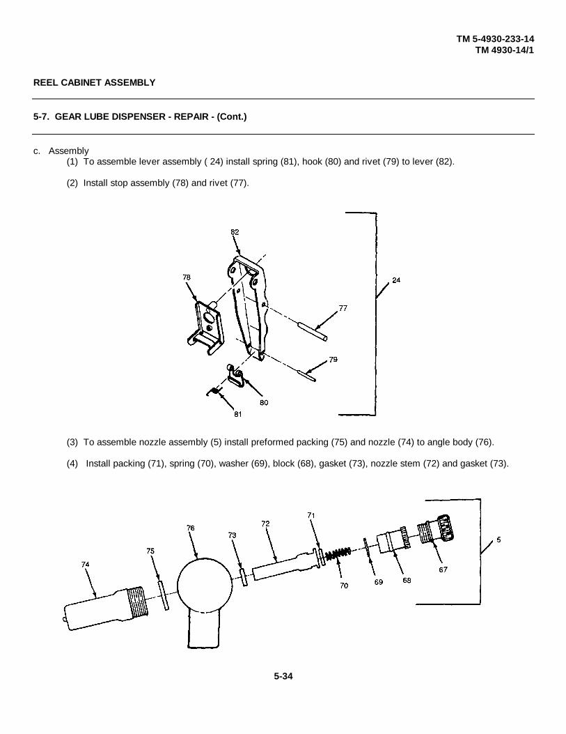
TM 5-4930-233-14TM 4930-14/1
REEL CABINET ASSEMBLY
5-7. GEAR LUBE DISPENSER - REPAIR - (Cont.)
c. Assembly(1) To assemble lever assembly ( 24) install spring (81), hook (80) and rivet (79) to lever (82).
(2) Install stop assembly (78) and rivet (77).
(3) To assemble nozzle assembly (5) install preformed packing (75) and nozzle (74) to angle body (76).
(4) Install packing (71), spring (70), washer (69), block (68), gasket (73), nozzle stem (72) and gasket (73).
5-34

TM 5-4930-233-14TM 4930-14/1
REEL CABINET ASSEMBLY
5-7. GEAR LUBE DISPENSER - REPAIR - (Cont.)
(5) To assemble totalizer (4) coat gears with light coating of grease and install odometer assembly (65), washer(64), gear assembly (63), bracket and gear assembly (62), lockwasher (61) and screw (60) to base plate(66).
(6) To assemble dial assembly (2) install clutch (58) two rollers ( 57) two springs (56), spring (55), pin (54), plate(53) and two screws (52) to knob (59).
(7) Install window (51) with two screws (50) to dial (49).
(8) Install dial (49), washer (48) and ring (47).
CAUTIONStrainer (37) is easily damaged.
(9) Install two plates (44) and four screws (45) to meter housing.
5-35
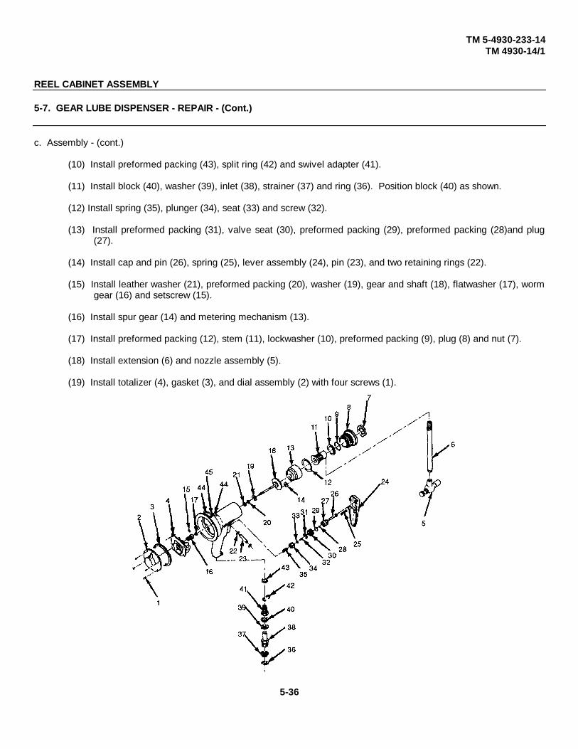
TM 5-4930-233-14TM 4930-14/1
REEL CABINET ASSEMBLY
5-7. GEAR LUBE DISPENSER - REPAIR - (Cont.)
c. Assembly - (cont.)
(10) Install preformed packing (43), split ring (42) and swivel adapter (41).
(11) Install block (40), washer (39), inlet (38), strainer (37) and ring (36). Position block (40) as shown.
(12) Install spring (35), plunger (34), seat (33) and screw (32).
(13) Install preformed packing (31), valve seat (30), preformed packing (29), preformed packing (28)and plug(27).
(14) Install cap and pin (26), spring (25), lever assembly (24), pin (23), and two retaining rings (22).
(15) Install leather washer (21), preformed packing (20), washer (19), gear and shaft (18), flatwasher (17), wormgear (16) and setscrew (15).
(16) Install spur gear (14) and metering mechanism (13).
(17) Install preformed packing (12), stem (11), lockwasher (10), preformed packing (9), plug (8) and nut (7).
(18) Install extension (6) and nozzle assembly (5).
(19) Install totalizer (4), gasket (3), and dial assembly (2) with four screws (1).
5-36

TM 5-4930-233-14TM 4930-14/1
REEL CABINET ASSEMBLY
5-8. ENGINE OIL DISPENSER - REPAIR
This task covers:
a. Disassembly b. Repair c. Assembly
INITIAL SET-UP:
Materials/Parts Equipment ConditionDry cleaning Solvent Engine oil dispenser removed(Item 6, App. E) (para 4-19)
ToolsGeneral MechanicsTool Box (Section III, Item 1, App B)
a. Disassembly
(1) Remove four screws (1) and remove dial assembly (2), gasket (3) and totalizer (4).
(2) Remove nozzle assembly (5) and extension (6).
(3) Remove outlet fitting body (7), preformed packing (8), metering mechanism (9) and spur gear (10).
(4) Remove setscrew (12), worn gear (13), flatwasher (14), gear and shaft (11), lockwasher (15), preformedpacking (16) and leather washer (17).
(5) Remove two retaining rings (18), pin (19), lever assembly (20), spring (21) and cap and pin (22).
(6) Remove plug (23), preformed packing (24), preformed packing (25), valve seat (26) and preformedpacking (27).
(7) Remove screw (28), seat (29), plunger (30) and spring (31).
(8) Remove stem (32), lockwasher (33) and block (34).
(9) Remove swivel adapter (35), preformed packing (36), and split ring (37).
NOTE
Remove two plates (39) only if illegible.
(10) Remove four screws (38) and two plates (39) from meter housing (40).
5-37
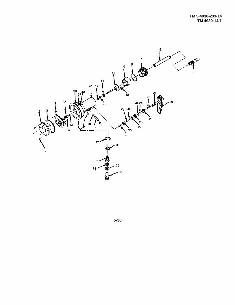
TM 5-4930-233-14TM 4930-14/1
5-38
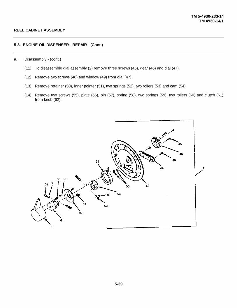
TM 5-4930-233-14TM 4930-14/1
REEL CABINET ASSEMBLY
5-8. ENGINE OIL DISPENSER - REPAIR - (Cont.)
a. Disassembly - (cont.)
(11) To disassemble dial assembly (2) remove three screws (45), gear (46) and dial (47).
(12) Remove two screws (48) and window (49) from dial (47).
(13) Remove retainer (50), inner pointer (51), two springs (52), two rollers (53) and cam (54).
(14) Remove two screws (55), plate (56), pin (57), spring (58), two springs (59), two rollers (60) and clutch (61)from knob (62).
5-39
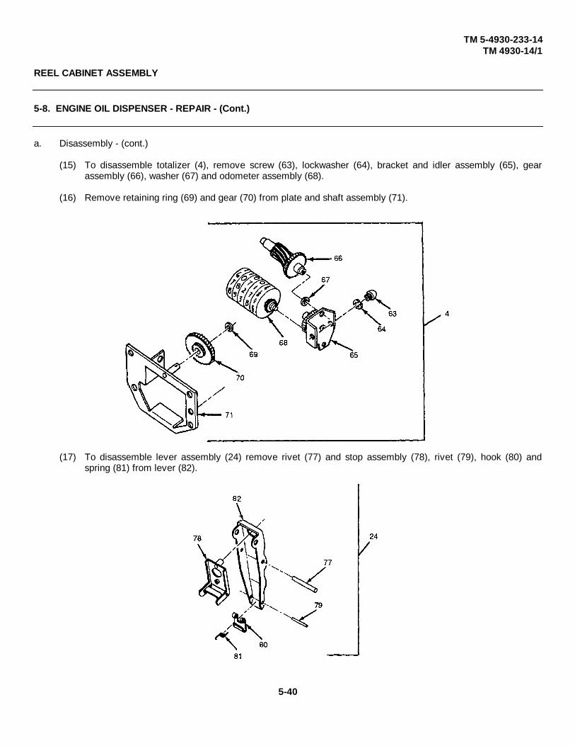
TM 5-4930-233-14TM 4930-14/1
REEL CABINET ASSEMBLY
5-8. ENGINE OIL DISPENSER - REPAIR - (Cont.)
a. Disassembly - (cont.)
(15) To disassemble totalizer (4), remove screw (63), lockwasher (64), bracket and idler assembly (65), gearassembly (66), washer (67) and odometer assembly (68).
(16) Remove retaining ring (69) and gear (70) from plate and shaft assembly (71).
(17) To disassemble lever assembly (24) remove rivet (77) and stop assembly (78), rivet (79), hook (80) andspring (81) from lever (82).
5-40

TM 5-4930-233-14TM 4930-14/1
REEL CABINET ASSEMBLY
5-8. ENGINE OIL DISPENSER - REPAIR - (Cont.)
b. Repair
WARNING
Worn or damaged parts can cause equipment malfunction which can lead toserious injury or equipment damage. Replace all damaged or worn parts.
(1) Replace all parts that are included in repair parts kit (TM 5-4930-233-24P).
WARNING
Clean all parts in a well ventilated area. Avoid inhaling solvent fumes andprolonged exposure of the skin to cleaning solvent. Failure to do so can causesevere injury or death. Do not use near flame or excessive heat. Flash point ofsolvent is 100°F - 138°(380C - 590C).
(2) Clean all parts with dry cleaning solvent thoroughly. Small particles of dirt or foreign matter can causemalfunction.
(3) Inspect gears for chipped or broken teeth. Replace as needed.
(4) Inspect all parts for damaged threads, wear, deterioration or damage. Replace any damaged or worn parts.
5-41

TM 5-4930-233-14TM 4930-14/1
REEL CABINET ASSEMBLY
5-8. ENGINE OIL DISPENSER - REPAIR - (Cont.)
c. Assembly
(1) To assemble lever assembly (24) install spring (81), hook (80) and rivet (79) to lever (82).
(2) Install stop assembly (78) and rivet (77).
(3) To assemble totalizer (4) lightly coat gears with grease and install gear (70) and retaining ring (69) to plateand shaft assembly (71).
(4) Install odometer assembly (68), washer (67), gear assembly (66), bracket and idler assembly (65),lockwasher (64) and screw (63).
5-42

TM 5-4930-233-14TM 4930-14/1
REEL CABINET ASSEMBLY
5-8. ENGINE OIL DISPENSER - REPAIR- (Cont.)
(5) To assemble dial assembly (2) install clutch (61), two rollers (60), two springs (59), spring (58), pin (57), plate(56) and two screws (55) to knob (62).
(6) Install cam (54), two rollers (53), two springs (52), inner pointer (51) and retainer (50).
(7) Install window (49) with two screws (48) to dial (47).
(8) Install dial (47), gear (46) and three screws (45).
5-43
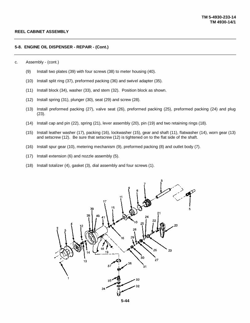
TM 5-4930-233-14TM 4930-14/1
REEL CABINET ASSEMBLY
5-8. ENGINE OIL DISPENSER - REPAIR - (Cont.)
c. Assembly - (cont.)
(9) Install two plates (39) with four screws (38) to meter housing (40).
(10) Install split ring (37), preformed packing (36) and swivel adapter (35).
(11) Install block (34), washer (33), and stem (32). Position block as shown.
(12) Install spring (31), plunger (30), seat (29) and screw (28).
(13) Install preformed packing (27), valve seat (26), preformed packing (25), preformed packing (24) and plug(23).
(14) Install cap and pin (22), spring (21), lever assembly (20), pin (19) and two retaining rings (18).
(15) Install leather washer (17), packing (16), lockwasher (15), gear and shaft (11), flatwasher (14), worn gear (13)and setscrew (12). Be sure that setscrew (12) is tightened on to the flat side of the shaft.
(16) Install spur gear (10), metering mechanism (9), preformed packing (8) and outlet body (7).
(17) Install extension (6) and nozzle assembly (5).
(18) Install totalizer (4), gasket (3), dial assembly and four screws (1).
5-44

TM 5-4930-233-14TM 4930-14/1
REEL CABINET ASSEMBLY
5-9. GREASE CONTROL VALVE - REPAIR/ADJUST
This task covers:
a. Disassembly b. Repair c. Assembly d. Adjustment
INITIAL SET-UP:
Materials/Parts Equipment Condition ToolsDry cleaning solvent Grease Control Valve General Mechanics Tool Box(Item 6, App. E) Removed (para. 4-19) (Section Ill, Item 1, App B)
a. Disassembly
(1) Remove hydraulic coupler (1) and extension (2).
(2) Remove screw (3), lockwasher (4), support casting (5), setscrew (6) and lever assembly (7).
(3) Remove packing plug (8), two preformed packings (9) and leather washer (10) between items (9) inside (8).
(4) Remove retaining bushing (11) and fittings from body (12).
(5) Remove two gaskets (13), valve assembly (14), spacer (15), gasket (16), spring (17), washer (18), andplunger stem (19).
(6) Loosen locknut (20) and remove adjustment screw (21) and packing ring (22) from retaining bushing (11).
(7) Remove connector (23), preformed packing (24), spring (25), valve seat (26) and locknut (20) fromadjustment screws (21).
5-45
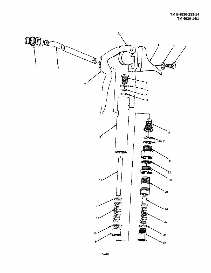
TM 5-4930-233-14TM 4930-14/1
5-46

TM 5-4930-233-14TM 4930-14/1
REEL CABINET ASSEMBLY
5-9. GREASE CONTROL VALVE - REPAIR/ADJUST - (Cont.)
b. Repair
WARNING
Worn or damaged parts can cause equipment malfunction which can lead toserious injury or equipment damage. Replace all damaged or worn parts.
(1) Replace all parts that are included in repair parts kit (TM 5-4930-233-24P).
WARNING
Clean all parts in a well ventilated area. Avoid inhaling solvent fumes andprolonged exposure of the skin to cleaning solvent. Failure to do so can causesevere injury or death. Do not use near flame or excessive heat. Flash point ofsolvent is 100°F - 138°F (38°C - 59°).
(2) Clean all parts with dry cleaning solvent thoroughly. Small particles of dirt or foreign matter can causemalfunction.
(3) Inspect all parts for damaged threads, wear, deterioration or damage. Replace any damaged or worn parts.
c. Assembly
(1) Install locknut (20), valve seat (26), spring (25), preformed packing (24) and connector (23) to adjustmentscrew (21).
(2) Install packing ring (22), adjustment screw (21) and locknut (20) to retaining bushing (11).
(3) Install plunger stem (19), washer (18), spring (17), gasket (16), spacer (15), valve assembly (14) and twogaskets (13).
(4) Install retaining bushing (11) to body (12).
(5) Install lever assembly (7), setscrew (6), support casting (5), lockwasher (4) and screw (3).
(6) Install extension (2) and hydraulic coupler (1).
(7) Adjust grease control valve (para. 5-9d).
5-47
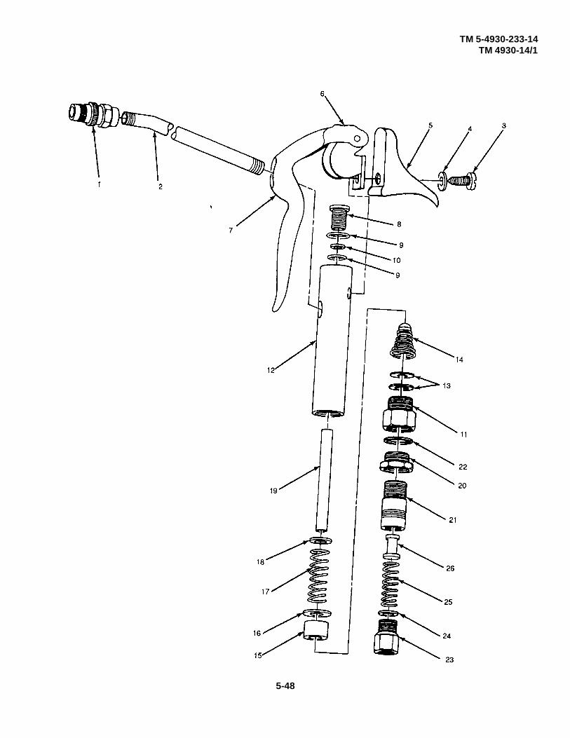
TM 5-4930-233-14TM 4930-14/1
5-48

TM 5-4930-233-14TM 4930-14/1
REEL CABINET ASSEMBLY
5-9. GREASE CONTROL VALVE - REPAIR/ADJUST- (Cont.)
d. Adjustment
(1) Tighten setscrew (6) so that there is 1/8 inch (3.175 mm) clearance between bottom of lever (7), hole andextension (2).
(2) To adjust for single shot delivery, disconnect grease control valve from lube hose.
CAUTION
Do not force adjustment screw (21) as damage to equipment can result.
(3) Loosen locknut (20) and turn adjustment screw (21) clockwise until a definite stop is felt.
(4) Turn adjustment screw (21) back (counterclockwise) approximately one and a quarter turns. Tighten locknut(20).
(5) Reconnect control valve to hose and test single shot delivery.
(6) If delivery volume in single shot mode is unsatisfactory, the following readjustment procedure should beperformed.
WARNING
The adjustment procedure which follows can be dangerous for unskilled personnelbecause improper loosening of the nuts and adjustment screw could cause thecontrol valve connections to blow apart with resultant injury to personnel andproperty, since lubricant is under high pressure.
(7) Disconnect control valve from lube hose.
(8) Loosen locknut (20) approximately 1/8 turn but do not allow locknut to come off.
(9) Turn adjustment screw (21) about an eighth of a turn clockwise to decrease delivery, or turn screwcounterclockwise to increase amount of lubricant delivered.
(10) Tighten locknut (20) and test delivery.
(11) If delivery is unsatisfactory, repeat steps (7) through (10).
5-49

TM 5-4930-233-14TM 4930-14/1
5-50

TM 10493G233-14TM 4930-14/1
REEL CABINET ASSEMBLY
5-11. AIR COMPRESSOR ASSEMBLY - TEST
This task covers:
Test
INITIAL SET-UP:
References ToolsTB 43-0151 General Mechanics Tool BoxInspection and test (Section III, Item 1, App B)of air and other gascompressors.
Test
Perform tests as required by TB 43-0151 for direct support maintenance. These tests should be performedperiodically as indicated.
Change 1 5-51/(5-52 blank)

TM 5-4930-233-14TM 4930-14/1
AIR COMPRESSOR ASSEMBLY
5-12. STARTER - REPAIR
This task covers:
a. Disassembly b. Repair c. Assembly d. Test
INITIAL SET-UP:
Materials/Parts Equipment Condition PageDry cleaning solvent Starter removed (para. 4-23)(Item 6, App. E)Cloth (Item 22, App E) Tools
General Mechanics Tool Box (Section III, Item 1,App B)Lathe (Section III, Item 9, App B)Multimeter (Section III, Item 4, App B)
a. Disassembly
(1) Remove two screws (1) and two lockwashers (2).
(2) Remove one nut (3) and one lockwasher (4).
(3) Remove two screws (5), two lockwashers (6) and solenoid switch (7).
(4) Separate housing (8) from shift lever housing (9).
(5) Remove pin (10) from shift lever housing (9).
(6) Remove four screws (11), separate shift lever housing (9) from drive housing (12)
(7) Remove spring (13), core assembly (14), forkshifter (15), motor armature assembly (16) and two washers(17).
(8) Remove brushes (18) and brush holders (19).
(9) Remove grommet (20) from housing (8).
(10) Remove field coils (21) and field assembly (22) from housing (8).
5-53
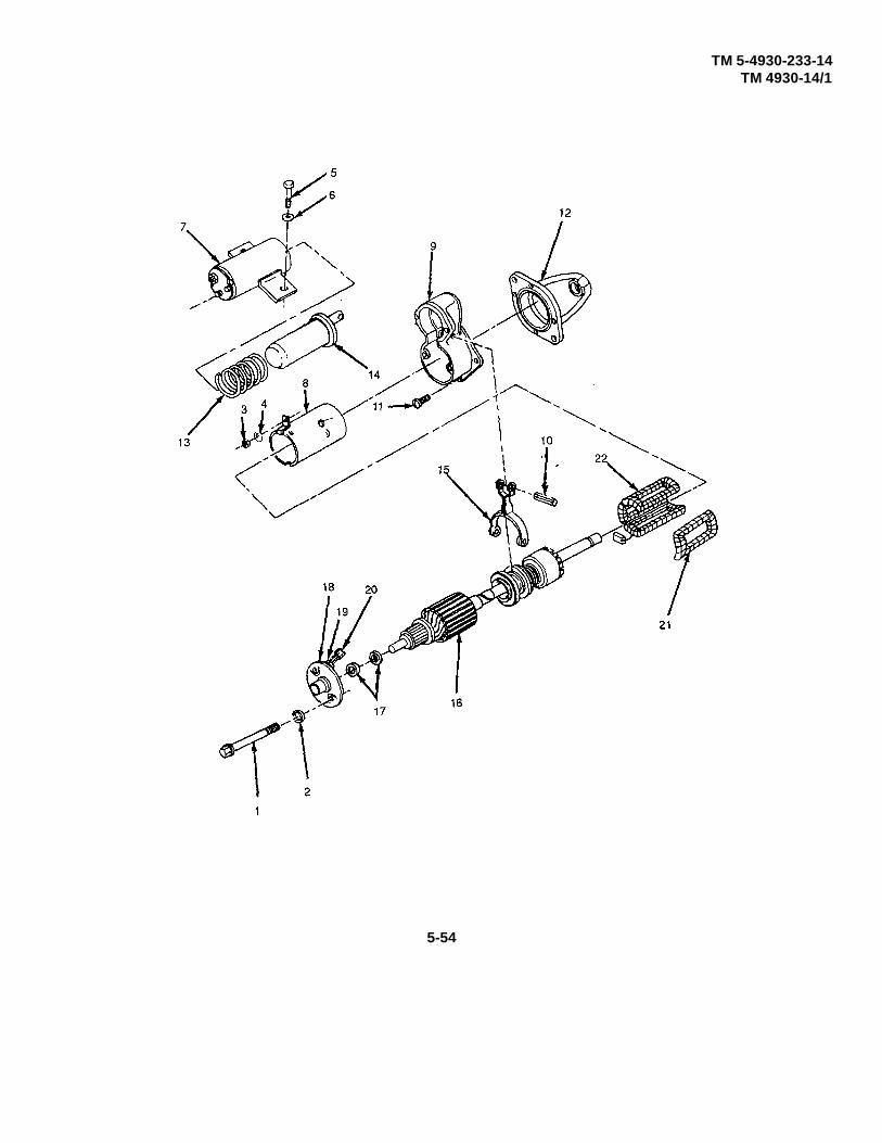
TM 5-4930-233-14TM 4930-14/1
5-54

TM 5-4930-233-14TM 4930-14/1
AIR COMPRESSOR ASSEMBLY
5-12. STARTER - REPAIR - (Cont.)
b. Repair
WARNING
Clean all parts in a well ventilated area. Avoid inhaling solvent fumes andprolonged exposure of the skin to cleaning solvent. Failure to do so can causesevere injury or death. Do not use near flame or excessive heat. Flash point ofsolvent is 100°F to 138°F (38°C to 59°C).
(1) Use a cloth dampened with dry cleaning solvent to wipe all dust, oil, and other foreign material from thebrush plates, end frames, and armature and field assemblies.
(2) Use filtered compressed air to blow dust and dirt from the crevices of the armature and field windings.
(3) Secure armature in a lathe with armature spinning, hold a sheet of No. 000 sandpaper against thecommutator until the copper is bright and smooth.
(4) Examine field frame assembly for cracks or warping. Inspect armature shaft end for damage or wear.Replace defective parts.
(5) Examine clutch for broken or cracked teeth. Replace if damaged.
(6) Examine field coils for worn, burned, and frayed insulation. Be certain connections between field coils aresecure. Repair connections if necessary.
(7) Inspect springs for distortion or fatigue. Examine brushes for damage or excessive wear. Replace ifneeded.
(8) Check brushholder for shorts. Replace if shorted.
(9) Test armature assembly for open coils and shorts to ground, or between coils.
(10) Check field coils for open circuits and shorts to ground, or between coils.
(11) If commutator is out-of-round in excess of 0.001 inch (0.0254 mm) turn down on lathe.
(12) Replace all parts indicating wear, cracks, or damage.
(13) Undercut mica insulation between the commutator bars to a depth of 1/32 of an inch (.7937 mm). Whenundercutting mica, the cut should be square and free of burrs.
5-55

TM 5-4930-233-14TM 4930-14/1
AIR COMPRESSOR ASSEMBLY
5-12. STARTER - REPAIR - (Cont.)
c. Assembly
(1) Install field assembly (22) and field coils (21) in housing (8).
(2) Install grommet (20) in housing (8).
(3) Install brush holders (19) and brushes (18).
(4) Install two washers (17), motor armature assembly (16), forkshifter (15), core assembly (14) and spring (13)into shift lever housing (9).
(5) Install drive housing (12) into shift lever housing (9) with four screws (11).
(6) Install pin (10) into shift lever housing (9).
(7) Position shift lever housing (9) and housing (8).
(8) Install solenoid switch (7), two lockwashers (6) and two screws (5) into housing (8).
(9) Install lockwasher (4) and nut (3).
(10) Install two lockwashers (2) and two screws (1).
5-56

TM 5-4930-233-14TM 4930-14/1
AIR COMPRESSOR ASSEMBLY
5-12. STARTER - REPAIR - (Cont.)
d. Test
(1) Connect the starting motor to a 24 volt dc supply. With an ammeter and voltmeter connected in the circuit,apply voltage to the starting motor.
(2) With the starting motor armature turning approximately 6,000 rpm, the ammeter should be indicating 23volts.
5-57

TM 5-4930-233-14TM 4930-14/1
AIR COMPRESSOR ASSEMBLY
5-13. ALTERNATOR - REPAIR
This task covers:
a. Disassembly b. Repair c. Assembly
INITIAL SET-UP:
Materials/Parts Equipment Condition ToolsSolvent, PD-680a, Type III Alternator Removed General Mechanics Tool Box
(Item 19, App E) (para 4-24) (Section III, Item 1, App B)Soft Bristle Brush Muftimeter (Section III, Item 4, App B)
(Item 24, App E) Solder Gun (Section III, Item 3, App B)Solder Lead, Tin
(Item 16, App E)Cloth (Item 22, App E)
a. Disassembly
(1) Remove three screws (1) which secure cover and connector assembly (2) to housing (3).
(2) Remove two nuts (4), two lockwashers (5), tag and disconnect leads from cover and connector assembly (2).
(3) Remove cover and connector assembly (2).
(4) Remove eight screws (6) which secure housing (3) to front housing (7) and remove housing (3).
(5) Remove two nuts (4), two washers (5), two spacers (8).
(6) Remove three screws (10), two nuts (35), two lockwashers (36), tag and disconnect leads from regulator (12),and remove regulator.
(7) Remove two screws (11) and remove cover (13) and brush assembly (14).
CAUTION
Because it may damage stator windings, do not use sharp tools between front and rear housings:
(8) Mark front and rear housings for use in assembly. Remove nut (9), lockwasher (8), three nuts withstarwashers attached (34), three flatwashers (33) and three insulators (32).
9) Remove four bolts (15) and nuts (16) to free rear housing (17). While gently rapping with rawhide hammer,worm rear housing (17) free.
5-58
TM 5-4930-233-14TM 4930-14/1
AIR COMPRESSOR ASSEMBLY
5-13. ALTERNATOR - REPAIR - (Cont.)
(10) Remove two rectifier diode assemblies (18) and place spacers (19) and washers (20) over threaded studs ofdiode assemblies.
CAUTION
To prevent possible damage to rectifier diodes when unsoldering, grasp diodeconnections with long nose pliers or other heat sink device.
(11) As required unsolder leads from stator (37) going to diode assemblies (18) and remove diode assemblies.
(12) Remove nut (21) and lockwasher (22) from end of rotor assembly (23) by locking nut (21) in bench vise andturning rotor assembly (23) by hand.
(13) Remove pulley (24) and fan (25) from end of rotor assembly (23).
(14) Slip woodruff key (26) and spacer (27) off end of rotor assembly (23).
(15) Remove retaining ring (28) and two bearings (29).
(16) Remove cap (30) and fuse (31) from cover (2).
5-59

TM 5-4930-233-14TM 4930-14/1
5-60

TM 5-4930-233-14TM 4930-14/1
AIR COMPRESSOR ASSEMBLY
5-13. ALTERNATOR - REPAIR - (Cont.)
b. Repair
CAUTION
Do not immerse alternator assembly in cleaning solvent of any kind. Do not deanisolation diodes with cleaning solvent. The diodes are coated with a specialcorrosion resistant paint. Failure to follow this caution can lead to severeequipment damage.
WARNING
Cleaning solvent is flammable and toxic to the skin, eyes, and respiratory tract.Skin, eye, and respiratory tract protection is required.
(1) Clean parts with a soft bristle brush moistened with tri-ethane.
WARNING
Compressed air used for cleaning or drying can create airborne particles that mayenter the eyes. Pressure shall not exceed 30 psi (207 KPa). Wearing of goggles isrequired.
(2) Dry parts with filtered, low-pressure compressed air or a clean lint-free cloth.
(3) Inspect brush assembly for excessive wear, replace brush assembly if 3/16 of inch (4.76 mm) or less extendsbeyond bottom of holder.
(4) Check brush assembly spnring tension with suitable spring scale. Spring tension should be 4 to 6 ounces(112 to 168 grams).
(5) Test rectifier diode in heat sinks connecting one of multimeter leads to the heat sink and the other multimeterlead to the diode stem, and note the reading. Then reverse the multimeter lead connections, and note thereading. If both readings are very low, of if both readings are very high, the diode is defective. A good diodewill give one low reading and one high reading (at least 100 times the low reading).
(6) Test isolation diode assembly by connecting one of the multimeter test leads to the output terminal stud ofthe diode, the other to the exposed metal area on heat sink, and note reading. Then reverse the leadconnections and note reading. If both readings are very low, or if both readings are very high, the diode isdefective.
5-61

TM 5-930-233-14TM 4930-14/1
AIR COMPRESSOR ASSEMBLY
5-13. ALTERNATOR - REPAIR - (Cont.)
b. Repair (cont.)
(7) Test stator assembly for grounds and opens as follows:
(a) Connect the multimeter (set to lowest resistance range) to two pairs of stator leads; if reading is veryhigh (over 10 ohms) the stator winding is open.
(b) To test the stator for grounds, connect the multimeter from any stator lead to the ground screw or theshell, and note the reading. If reading is very low, the stator is shorted to ground (defective).
(8) Test rotor assembly for grounds between slip ring and shaft, using a multimeter. An open circuit from eitherslip ring to shaft is a correct condition.
(9) Perform resistance check on rotor assembly windings using a multimeter; resistance should be between 11 to14 ohms.
(10) Test voltage regulator by connecting multimeter leads to regulator leads as follows:
(a) Connect multimeter lead (+) to regulator yellow lead and multimeter lead (-) to regulator red lead;multimeter should indicate between 300 to 350 ohms.
(b) Connect multimeter lead (+) to regulator red lead and multimeter lead (-) to regulator yellow lead;multimeter should indicate an open circuit.
(c) If above readings are not obtained, replace regulator.
(11) Inspect fan for cracked or broken fins. Check fan bore for wear.
(12) Inspect pulley for worn drive surfaces and condition of key groove. Check pulley bore for wear.
(13) Inspect front bearing cavity for evidence of wear. Check condition of retainer recess.
(14) Check slip rings for pitting, roughness, or burned spots. If surface is worn beyond repair, replace entire rotorassembly.
(15) Inspect rotor shaft for key slot wear, worn bearing surfaces, scuff marks on pole fingers, and condition ofthreads on pulley nut.
(16) Inspect bearings for scored, pitted, scratched, cracked, or chipped races.
(17) Replace any part or component that is damaged, worn or defective.
5-62
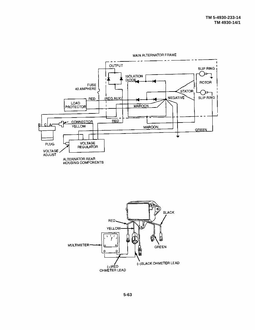
TM 5-4930-233-14TM 4930-14/1
5-63
TM 5-4930-233-14TM 4930-14/1
AIR COMPRESSOR ASSEMBLY
5-13. ALTERNATOR - REPAIR - (Cont.)
c. Assembly
NOTE
Refer to alternator wiring diagram when connecting electrical leads.
(1) Press two bearings (29) in front and rear housings (17 and 7), respectively.
(2) Install two retaining rings (28) to secure bearings in place.
(3) Place longer end of rotor assembly (23) shaft through front housing (7).
(4) Place spacer (27) over longer end of shaft.
(5) Place woodruff key (26) into mechanical keyway in longer end of shaft.
(6) Align slots in fan (25) and pulley (24) with woodruff key and press over end of shaft.
(7) After placing washer (22) over end of shaft, screw (finger tight) nut (21) onto threaded end of shaft.
(8) To prevent rotor assembly (23) from turning when tightening nut (21), wrap an oversize belt around pulleyand clamp pulley in vise. Tighten nut (21).
(9) After placing washers (20) and spacers (19) over threaded studs of diode assemblies, install stator (37) andtwo diode assemblies (18) in rear housing (17).
NOTE
To prevent heat damage to rectifier diodes when soldering, use heat sink betweensoldering iron and diode.
(10) Reconnect stator leads as directed by tagging done during disassembly.
(11) Install nut (9), lockwasher (8), three nuts with starwashers attached (34), three flatwashers (33) and threeinsulators (32).
(12) After ensuring that rotor assembly (23) turns freely, secure front and rear housings in place with bolts (15)and nuts (16).
(13) Mount brush assembly (14) over rear housing (17) and secure in place with cover (13) and two screws (11).
5-64

TM 5-4930-233-14TM 4930-14/1
AIR COMPRESSOR ASSEMBLY
5-13. ALTERNATOR - REPAIR - (Cont.)
(14) Using two screws (10), two nuts (35), and two lockwashers (36) secure regulator (12) in place on rear housing(17). Connect leads from regulator as indicated by tagging diode during disassembly.
(15) Secure over threaded studs projection from rear housing (17) with spacers (8), washers (5), and nuts (4).
(16) Position housing (3) over alternator and secure in place with screws (6).
(17) Connect leads and connector with two nuts (4) and two lockwashers (5) as indicated by tagging done duringdisassembly.
(18) Using three screws (1), secure cover and connector assembly (2) in place over end of housing (3).
(19) Install fuse (31) and cap (30) in cover.
(20) Test alternator in accordance with para 4-24.
5-65
TM 5-4930-233-14TM 4930-14/1
AIR COMPRESSOR ASSEMBLY
5-14. AIR COMPRESSOR - REPAIR
This task covers:
a. Disassembly b. Repair c. Assembly
INITIAL SET-UP:
Materials/Parts Equipment ConditionDry Cleaning Solvent Air Compressor Removed(Item 6, App E) (para 4-29)Tape (Item 17, App. E) Air Compressor hose, lines and fittings
Removed (para 4-32)
ToolsGeneral Mechanics Tool Box(Section III, Item 1, App B)Torque Wrench(Section III, Item 6, App B)
a. Disassembly
(1) Remove intercooler (1) and air filter (2) from head (3).
(2) Disconnect and remove two breather tubes (4), three elbow breather connectors (5) and straight breatherconnector (6).
(3) Disconnect and remove unloading tube (7).
(4) Remove ten screws (8), cylinder head assembly (3) and gasket (9).
(5) Mark pistons (10) on flywheel side so they can be reinstalled in the same position.
(6) Remove six screws (11) and six lockwashers (15).
(7) Gently twist cylinder (12) back and forth while pulling upward to remove. Take care not to allow connectingrods and pistons to strike metal when cylinder is removed.
(8) Remove all traces of gasket (13) from cylinder (12) and base and cup assembly (14).
5-66
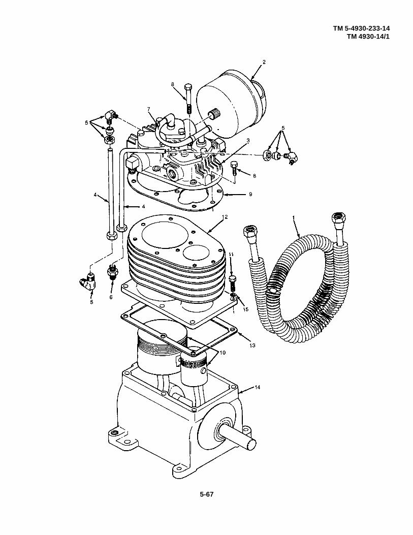
TM 5-4930-233-14TM 4930-14/1
5-67

TM 5-4930-233-14TM 4930-14/1
AIR COMPRESSOR ASSEMBLY
5-14. AIR COMPRESSOR - REPAIR - (Cont.)
a. Disassembly - (cont.)
WARNING
Take care that pistons are not scratched or damaged during removal.
(9) Remove elbow (16) and locknut (17).
(10) Remove six screws (19), end cover and cup assembly (20) and three gaskets (21).
(11) Remove two rivets (28), two weights (29), plunger (18), air valve (30), spring (31) and two bumper springs(32).
(12) Remove bearing cup (22) from end cover (23) only if damaged or if bearing (24) is to be replaced.
(13) Remove tape and key (25) from crankshaft and cone assembly (26). Slide crankshaft and cone assembly(26) along with pistons (10) and oil feeder ring (27) out of base and cup assembly (14) being careful not todamage feeder ring.
(14) Remove weight retainer and shaft (33) and washer (34) from crankshaft.
(15) Drive oil seal (35) out of base and cup assembly (14) only if replacement is required.
(16) Remove bearing cup (36) from base (37) only if damaged or if bearing (38) is to be replaced.
(17) Remove two plugs (39), oil filler plug (40) and gasket (41).
5-68

TM 5-4930-233-14TM 4930-14/1
5-69
TM 5-4930-233-14TM 4930-14/1
AIR COMPRESSOR ASSEMBLY
5-14. AIR COMPRESSOR - REPAIR - (Cont.)
a. Disassembly - (cont.)
(18) Drive two roll pins (42) into two wrist pins (43) and remove two wrist pins (43) and two pistons (10).
(19) Remove two roll pins (42) from wrist pins (43).
NOTE
Remove rings only if replacement is required.
(20) Remove top compression ring (44), bottom compression ring (45) and oil control ring (46) from high pressurepiston. Repeat for low pressure piston.
NOTE
When removing connection rods, be sure that rods and caps are kept in matched sets.
(21) Mark connecting rods so that they can be installed in the same position originally occupied. Remove twoscrews (47), two lockwashers (48), rod cap (49), rod (50) and two bearing inserts (51). Repeat for other rodassembly.
(22) Remove two pin bearings (52) only if replacement is required.
(23) Remove two bearings (24 and 38) from crankshaft (53).
5-70
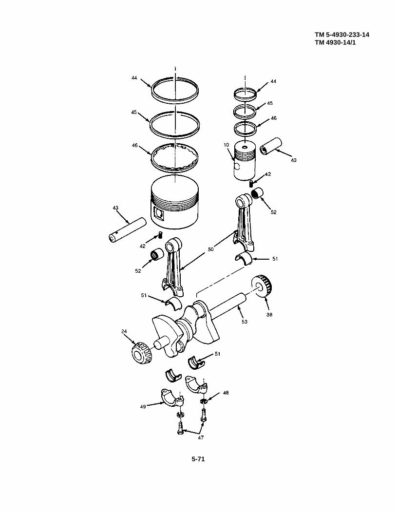
TM 5-4930-233-14TM 4930-14/1
5-71

TM 5-4930-233-14TM 4930-14/1
AIR COMPRESSOR ASSEMBLY
5-14. AIR COMPRESSOR - REPAIR - (Cont.)
b. Repair
WARNING
Clean all parts in a well ventilated area. Avoid inhaling solvent fumes and prolonged exposure ofthe skin to cleaning solvent. Failure to do so can cause severe injury or death. Do not use nearflame or excessive heat. Flash point of solvent is 100°F to 138°F (38°C to 59°C).
(1) Clear all metal parts thoroughly with dry cleaning solvent.
(2) Check piston fit. Pistons without rings should slide through the cylinder of their own weight and holding theskirt of the piston with the two thumbs there should be no appreciable side motion at any point of pistontravel. Scored or out of round cylinders or pistons should be replaced.
(3) Inspect all springs for loss of tension and set. Replace if defective.
(4) Inspect bearings and bearing cups for wear, scoring or damage. Replace if defective.
(5) Inspect cylinder for broken cooling fins and cracks. Replace if damaged.
(6) Inspect crankshaft for cracks, scores and distortion. Replace if defective.
(7) Inspect all parts for cracks, nicks, burns, wear or other damage. Replace, wrist pin must also be replaced.
NOTE
During assembly, check component fit as required by the procedure. Replace an item that isfound to be defective.
c. Assembly
(1) Install two bearings (38 and 24) on crankshaft (53).
(2) Press in two pin bearings (52) making sure that the small hole through casting lines up with oil hole in rod.
(3) Install two bearing inserts (51), rod (50), rod cap (49), two lockwashers (48) and two screws (47). Torquescrews (47) to 25 ft lbs (33.9 N-m). Repeat for other rod.
5-72

TM 5-4930-233-14TM 4930-14/1
AIR COMPRESSOR ASSEMBLY
5-14. AIR COMPRESSOR - REPAIR - (Cont.)
(4) Install oil controlling (46), bottom compression ring (45) and top compression ring (44) on high pressurepiston. Repeat for low pressure piston.
(5) Install two pistons (10) onto two rods (50) using two wrist pins (43). Piston should fit so that it can be rockedwith three fingers. The piston should not rock of its own weight. Replace wrist pin (43) and pin bearing (52)if required.
5-73

TM 5-4930-233-14TM 4930-14/1
AIR COMPRESSOR ASSEMBLY
5-14. AIR COMPRESSOR - REPAIR - (Cont.)
c. Assembly - (cont.)
(6) If fit is good, drive roll pin (42) into wrist pin (43) when holes are in line.
(7) At this time the combined piston and rod should turn slowly on the crankshaft of their own weight. If this isnot true, re-torque screws (47).
(8) Install gasket (41), oil filler plug (40) and two plugs (39).
(9) Install bearing cup (36) into base (37).
(10) Install washer (34) and weight retainer and shaft (33).
(11) Install key (25) and tape key in place.
(12) Install crankshaft and cone assembly (26) and oil feed ring (27) into base and cup assembly (14).
(13) Install bearing cup (22) into end cover (23).
(14) Install spring (31), air valve (30), two bumper springs (32), two weights (29), plunger (18) and two rivets (28)to weight retainer and shaft (33).
(15) Install end cover and cup assembly (20) and six screws (19) along with gaskets (21). Gaskets should beselected so that crankshaft can be spun in the bearings without end play. Also ensure that oil feed ring (27)turns freely within the guide lugs in the gasket. Torque screws (19) to 10 ft lbs (13.56 N-m).
(16) Slide oil seal (35) over crankshaft and press into place in the base. Be sure that the seal side is toward thecrankcase. Do not hammer directly on the seal.
(17) Install elbow (16) and locknut (17).
CAUTION
Do not screw elbow into end cover to far or malfunction of equipment can occur leading topermanent equipment damage.
(18) Screw elbow (16) into end cover and cup assembly (20) until part of valve (30) can be seen when lookinginto tube opening of elbow. Tighten jam nut.
5-74

TM 5-4930-233-14TM 4930-14/1
5-75
TM 5-4930-233-14TM 4930-14/1
AIR COMPRESSOR ASSEMBLY
5-14. AIR COMPRESSOR - REPAIR - (Cont.)
c. Assembly - (cont.)
(19) Install gasket (13) and cylinder (12) with six screws (11) and six lockwashers (15). Torque screws to 28 ft lbs(30 N-m).
(20) Install gasket (9), cylinder head assembly (3) and ten screws (8). Torque screws to 10 ft lbs (13.56 N-m).
(21) Install unloading tube (7).
(22) Install straight breather connector (6), three elbow breather connectors (5) and two breather tubes (4).
(23) Install air filter (2) and intercooler (1).
5-76

TM 5-4930-233-14TM 4930-14/1
5-77

TM 5-4930-233-14TM 4930-14/1
AIR COMPRESSOR ASSEMBLY
5-15. HEAD- REPLACE/REPAIR
This task covers:
a. Removal b. Disassembly c. Repair d. Assemblye. Installation
INITIAL SET-UP:
Materials/Parts ToolsDry Cleaning Solvent General Mechanics Tool Box(Item 6, App E) (Section III, Item 1, App B)
Torque Wrench 0-150 ft lbs(Section III, Item 6, App B)
a. Removal
(1) Vent all air pressure completely by turning lever (1).
(2) Remove intercooler (2) and air filter (3) from head (4).
(3) Disconnect and remove breather tube (5) and elbow breather connector (6).
5-78

TM 5-4930-233-14TM 4930-14/1
AIR COMPRESSOR ASSEMBLY
5-15. HEAD- REPLACE/REPAIR - (Cont.)
(4) Disconnect and remove unloading tube (7).
(5) Disconnect and remove pilot valve tube (8).
(6) Remove ten screws (9), cylinder head assembly (4) and gasket (10).
5-79
TM 5-4930-233-14TM 4930-14/1
AIR COMPRESSOR ASSEMBLY
5-15. HEAD- REPLACE/REPAIR - (Cont.)
b. Disassembly
(1) Disconnect and remove unloader tube (11).
(2) Remove elbow (12) and tee (13).
(3) Remove four screws (14), two inlet hold down cover assemblies (15), and two preformed packings (16).
(4) Remove locknut (17), fingers (18), bushing (19), plunger (20), preformed packing (21) and spring (22) fromcover (23). Repeat for other inlet hold down cover assembly.
(5) Remove two cages (24), two inlet valves (25) and two gaskets (26).
(6) Remove elbow (27).
(7) Remove four screws (28), two discharge hold down covers (29), and two preformed packings (30).
(8) Remove two cages (31), two discharge valves (32) and two gaskets (33).
5-80

TM 5-4930-233-14TM 4930-14/1
Change 1 5-81

TM 5-4930-233-14TM 4930-14/1
AIR COMPRESSOR ASSEMBLY
5-15. HEAD- REPLACE/REPAIR - (Cont.)
c. Repair
WARNING
Clean all parts in a well ventilated area. Avoid inhaling solvent fumes and prolonged exposure ofthe skin to cleaning solvent. Failure to do so can cause severe injury or death. Do not use nearflame or excessive heat. Flash point of solvent is 100°F to 138°F (38°C to 59°C).
(1) Clean all parts in dry cleaning solvent.
(2) Inspect all valve seat and cages for cracks, breaks, rough or scored seats and mating surfaces. Replace ifdefective.
(3) Inspect springs for distortion, weakness or broken coils. Replace if damaged.
(4) Inspect all other parts for wear, damage or corrosion. Replace as needed.
d. Assembly
(1) Install two gaskets (33), two discharge valves (32) and two cages (31).
(2) Install two preformed packings (30), two discharge hold down covers (29) and four screws (28). Torquescrews evenly to 10 ft lbs (13.56 N-m).
(3) Install elbow (27).
(4) Install two gaskets (26), two inlet valves (25) and two cages (24).
(5) Assemble inlet hold down cover assemblies (15) by installing spring (22), preformed packing (21), plunger(20), bushing (19), fingers (18) and locknut (17) into cover (23). Repeat for other inlet hold down coverassembly.
(6) Install two preformed packings (16), two inlet hold down cover assemblies (15) and four screws (14). Torquescrews evenly to 10 ft lbs (13.56 N-m).
(7) Install elbow (12) and tee (13).
(8) Install inloader tube (11).
5-82

TM 5-4930-233-14TM 4930-14/1
Change 1 5-83

TM 5-4930-233-14TM 4930-14/1
AIR COMPRESSOR ASSEMBLY
5-15. HEAD- REPLACE/REPAIR - (Cont.)
e. Installation
(1) Install gasket (10), cylinder head assembly (4) and ten screws (9). Torque screws to 10 ft lbs (13.56 N-m).
(2) Install pilot valve tube (8).
(3) Install unloading tube (7).
(4) Install elbow breather connector (6) and breather tube (5).
(5) Install air filter (3) and intercooler (2).
5-84
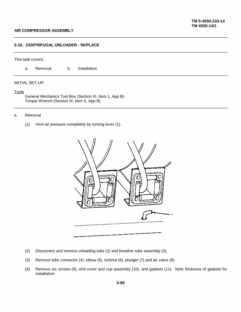
TM 5-4930-233-14TM 4930-14/1
AIR COMPRESSOR ASSEMBLY
5-16. CENTRIFUGAL UNLOADER - REPLACE
This task covers:
a. Removal b. Installation
INITIAL SET-UP:
ToolsGeneral Mechanics Tool Box (Section III, Item 1, App B)Torque Wrench (Section III, Item 6, App B)
a. Removal
(1) Vent air pressure completely by turning lever (1).
(2) Disconnect and remove unloading tube (2) and breather tube assembly (3).
(3) Remove tube connector (4), elbow (5), locknut (6), plunger (7) and air valve (8).
(4) Remove six screws (9), end cover and cup assembly (10), and gaskets (11). Note thickness of gaskets forinstallation.
5-85
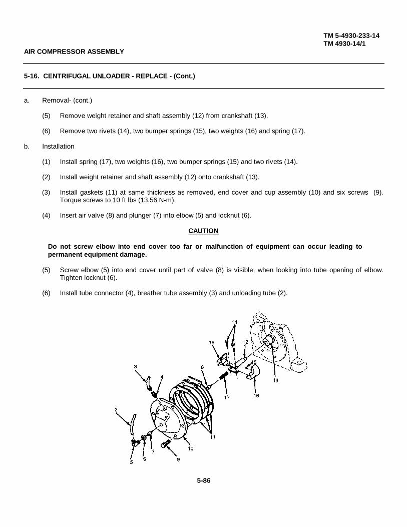
TM 5-4930-233-14TM 4930-14/1
AIR COMPRESSOR ASSEMBLY
5-16. CENTRIFUGAL UNLOADER - REPLACE - (Cont.)
a. Removal- (cont.)
(5) Remove weight retainer and shaft assembly (12) from crankshaft (13).
(6) Remove two rivets (14), two bumper springs (15), two weights (16) and spring (17).
b. Installation
(1) Install spring (17), two weights (16), two bumper springs (15) and two rivets (14).
(2) Install weight retainer and shaft assembly (12) onto crankshaft (13).
(3) Install gaskets (11) at same thickness as removed, end cover and cup assembly (10) and six screws (9).Torque screws to 10 ft lbs (13.56 N-m).
(4) Insert air valve (8) and plunger (7) into elbow (5) and locknut (6).
CAUTION
Do not screw elbow into end cover too far or malfunction of equipment can occur leading topermanent equipment damage.
(5) Screw elbow (5) into end cover until part of valve (8) is visible, when looking into tube opening of elbow.Tighten locknut (6).
(6) Install tube connector (4), breather tube assembly (3) and unloading tube (2).
5-86

TM 5-4930-233-14TM 4930-14/1
LUBE TANK ASSEMBLY
5-17. AIR REGULATOR - REPAIR
This task covers:
a. Disassembly b. Repair c. Assembly
INITIAL SET-UP:
Materials/Parts Equipment ConditionDry cleaning Solvent Air Regulator Removed(Item 6, App E) (para 4-36)Primer, Sealing Compound(Item 9, App E) ToolsSealing Compound General Mechanics Tool Box(Item 10, App E) (Section III, Item 1, App B)
a. Disassembly
(1) Remove adjusting screw (1) and check nut (2) at top of regulator
WARNING
Bottom plug is spring loaded. Remove with extreme care to avoid personal injury.
(2) Loosen and slowly remove bottom plug (3) and gasket (4).
(3) Remove spring (5) and disc assembly (6) and valve seat (7) from cavity.
(4) Remove six screws (8) at base of bonnet assembly (9) and lift it from body assembly (10).
(5) Remove spring pad (11), spring (12) and diaphragm assembly (13) from body assembly.
b. Repair
(1) Clean all metallic parts in dry cleaning solvent.
(2) Inspect valve seat for damage. Replace if required.
(3) Inspect diaphragm for deterioration, cracks or damage. Replace if needed.
(4) Inspect all parts for damage or wear. Discard defective items.
5-87
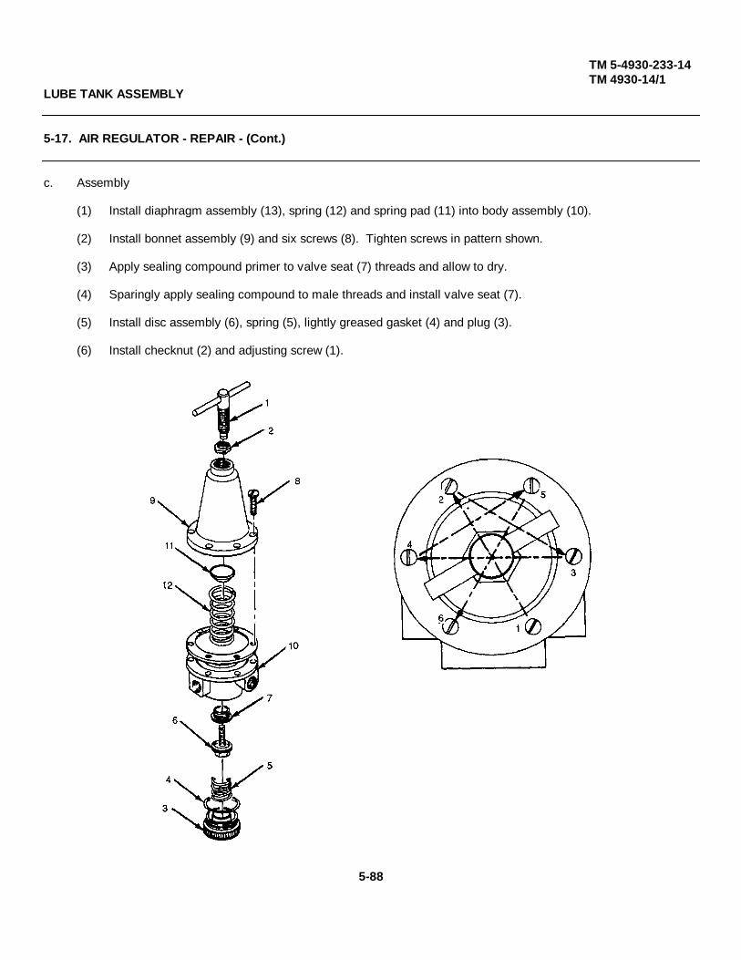
TM 5-4930-233-14TM 4930-14/1
LUBE TANK ASSEMBLY
5-17. AIR REGULATOR - REPAIR - (Cont.)
c. Assembly
(1) Install diaphragm assembly (13), spring (12) and spring pad (11) into body assembly (10).
(2) Install bonnet assembly (9) and six screws (8). Tighten screws in pattern shown.
(3) Apply sealing compound primer to valve seat (7) threads and allow to dry.
(4) Sparingly apply sealing compound to male threads and install valve seat (7).
(5) Install disc assembly (6), spring (5), lightly greased gasket (4) and plug (3).
(6) Install checknut (2) and adjusting screw (1).
5-88
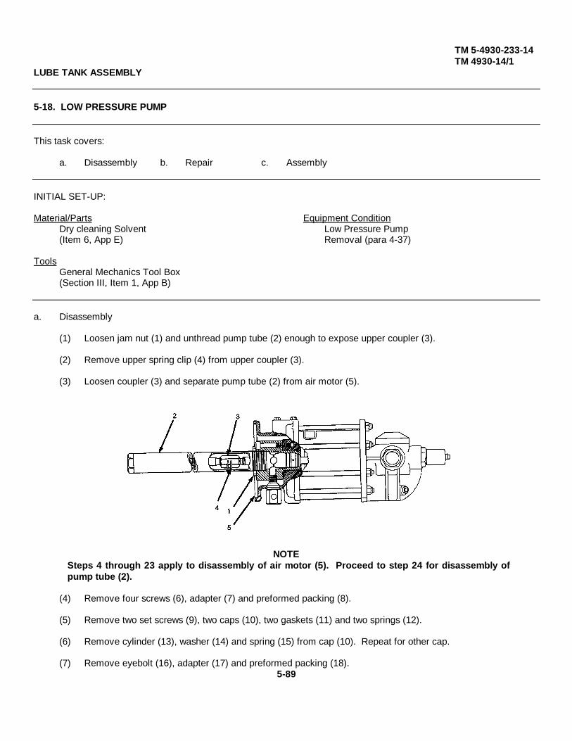
TM 5-4930-233-14TM 4930-14/1
LUBE TANK ASSEMBLY
5-18. LOW PRESSURE PUMP
This task covers:
a. Disassembly b. Repair c. Assembly
INITIAL SET-UP:
Material/Parts Equipment ConditionDry cleaning Solvent Low Pressure Pump(Item 6, App E) Removal (para 4-37)
ToolsGeneral Mechanics Tool Box(Section III, Item 1, App B)
a. Disassembly
(1) Loosen jam nut (1) and unthread pump tube (2) enough to expose upper coupler (3).
(2) Remove upper spring clip (4) from upper coupler (3).
(3) Loosen coupler (3) and separate pump tube (2) from air motor (5).
NOTESteps 4 through 23 apply to disassembly of air motor (5). Proceed to step 24 for disassembly ofpump tube (2).
(4) Remove four screws (6), adapter (7) and preformed packing (8).
(5) Remove two set screws (9), two caps (10), two gaskets (11) and two springs (12).
(6) Remove cylinder (13), washer (14) and spring (15) from cap (10). Repeat for other cap.
(7) Remove eyebolt (16), adapter (17) and preformed packing (18).5-89

TM 5-4930-233-14TM 4930-14/1
LUBE TANK ASSEMBLY
5-18. LOW PRESSURE PUMP (Cont.)
a. Disassembly - (cont.)
CAUTION
Do not scratch trip rod. This can lead to equipment damage and unnecessary failure.
NOTE
Nut (20) is secured with sealant.
(8) Lift shuttle (19) and secure inside the motor assembly as shown. Remove nut (20).
(9) Remove eight nuts (21) and lift valve body and stop assembly (22) off of tie rods. Remove preformedpacking (23).
(10) Remove shuttle (19), two plungers (24) and two toggles (25).
(11) Remove four screws (26), two valve guide and plug assemblies (27) two stops (28) and slide valve (29).
5-90

TM 5-4930-233-14TM 4930-14/1
LUBE TANK ASSEMBLY
5-18. LOW PRESSURE PUMP (Cont.)
CAUTION
Take care not to scratch valve side of seat during removal.
(12) Remove valve seat (30) and gasket (31).
(13) Remove plug (32).
(14) Pull air tube (33) from cylinder head and plug assembly (34) and remove two preformed packings (35).
(15) Lift out cylinder (36) and remove preformed packing (37).
(16) Remove retaining ring (38), washer (39) and block "v" packing (40) from underside of valve body and stopassembly (22).
(17) Loosen nut (41) and remove piston rod (42), two washers (43), packing (44) and nut (41).
(18) Secure trip rod (45) and remove nut (46), preformed packing (47) and nut (48).
(19) Remove plug (49), adapter (50), washer (51) and bushing (52).
(20) Remove six tie rods (53) and two screws (54).
Change 1 5-91
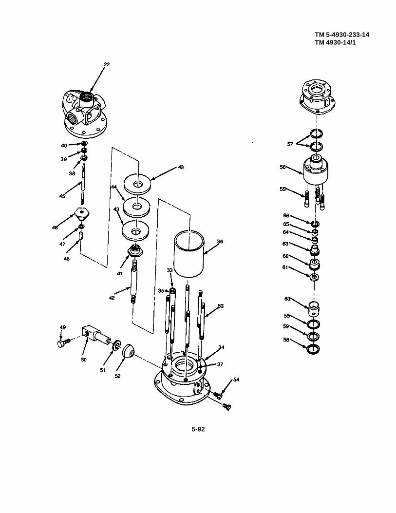
TM 5-4930-233-14TM 4930-14/1
5-92

TM 5-4930-233-14TM 4930-14/1
LUBE TANK ASSEMBLY
5-18. LOW PRESSURE PUMP (Cont.)
a. Disassembly - (cont.)
(21) Remove three screws (55), body (56) and two preformed packings (57).
(22) Remove two gaskets (58), washer (59) and spacer (60).
(23) Push out through bottom of body (56), washer (61), seal (62), lantern ring (63), seal (64), spacer (65) andpreformed packing (66).
5-93
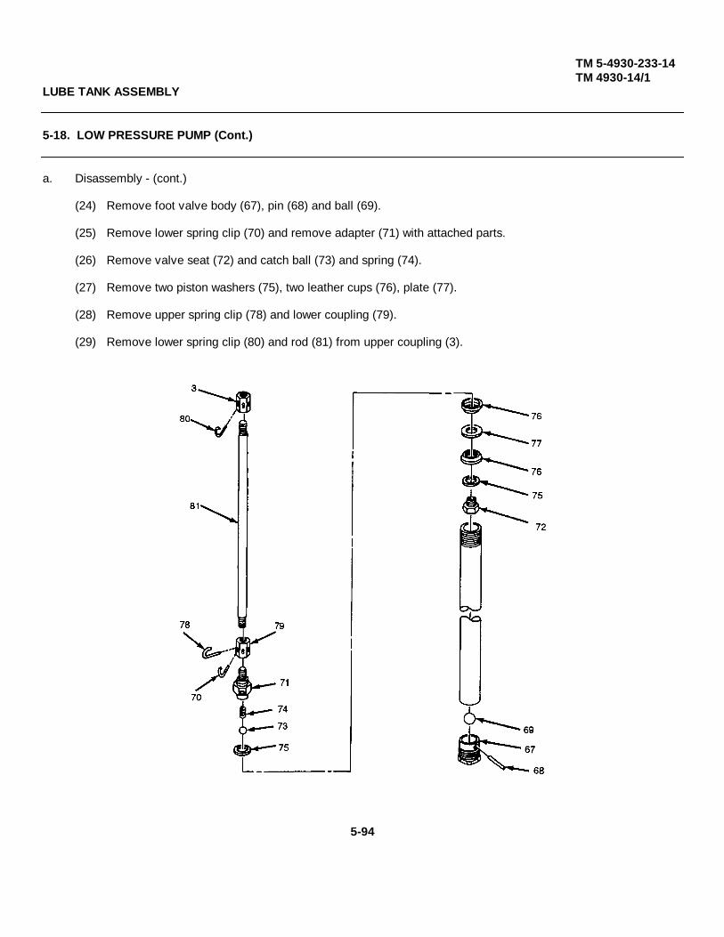
TM 5-4930-233-14TM 4930-14/1
LUBE TANK ASSEMBLY
5-18. LOW PRESSURE PUMP (Cont.)
a. Disassembly - (cont.)
(24) Remove foot valve body (67), pin (68) and ball (69).
(25) Remove lower spring clip (70) and remove adapter (71) with attached parts.
(26) Remove valve seat (72) and catch ball (73) and spring (74).
(27) Remove two piston washers (75), two leather cups (76), plate (77).
(28) Remove upper spring clip (78) and lower coupling (79).
(29) Remove lower spring clip (80) and rod (81) from upper coupling (3).
5-94
TM 5-4930-233-14TM 4930-14/1
LUBE TANK ASSEMBLY
5-18. LOW PRESSURE PUMP (Cont.)
b. Repair
WARNING
Clean all parts in a well ventilated area. Avoid inhaling solvent fumes and prolonged exposure ofthe skin to cleaning solvent. Failure to do so can cause severe injury or death. Do not use nearflame or excessive heat. Flash point of solvent is 100°F to 138°F (38°C to 59°C).
(1) Clean all parts with dry cleaning solvent.
(2) Discard and replace all gaskets and packings.
(3) Inspect and replace any worn or damaged parts.
(4) Inspect threaded surfaces for damage. Replace if defective.
(5) Inspect pump rods and tubes for cracks, breaks or other defects which would prevent proper operation.
(6) Inspect valve and valve seats for damage or wear. Replace as required.
5-95
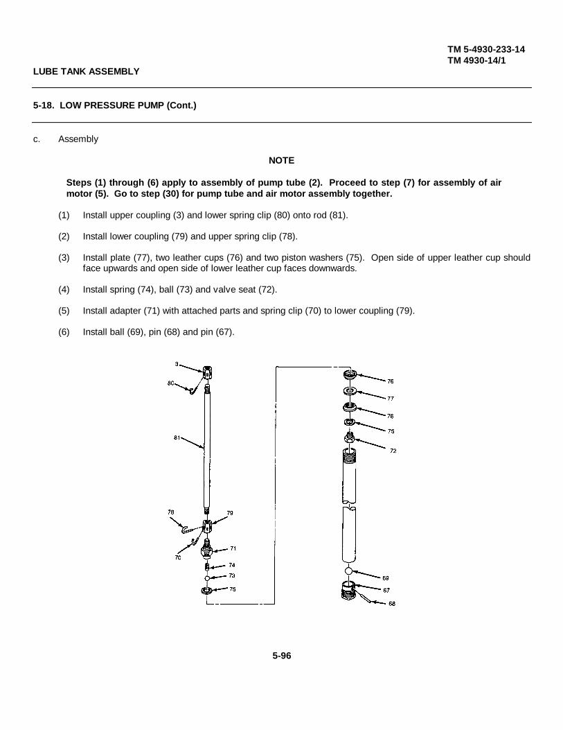
TM 5-4930-233-14TM 4930-14/1
LUBE TANK ASSEMBLY
5-18. LOW PRESSURE PUMP (Cont.)
c. Assembly
NOTE
Steps (1) through (6) apply to assembly of pump tube (2). Proceed to step (7) for assembly of airmotor (5). Go to step (30) for pump tube and air motor assembly together.
(1) Install upper coupling (3) and lower spring clip (80) onto rod (81).
(2) Install lower coupling (79) and upper spring clip (78).
(3) Install plate (77), two leather cups (76) and two piston washers (75). Open side of upper leather cup shouldface upwards and open side of lower leather cup faces downwards.
(4) Install spring (74), ball (73) and valve seat (72).
(5) Install adapter (71) with attached parts and spring clip (70) to lower coupling (79).
(6) Install ball (69), pin (68) and pin (67).
5-96
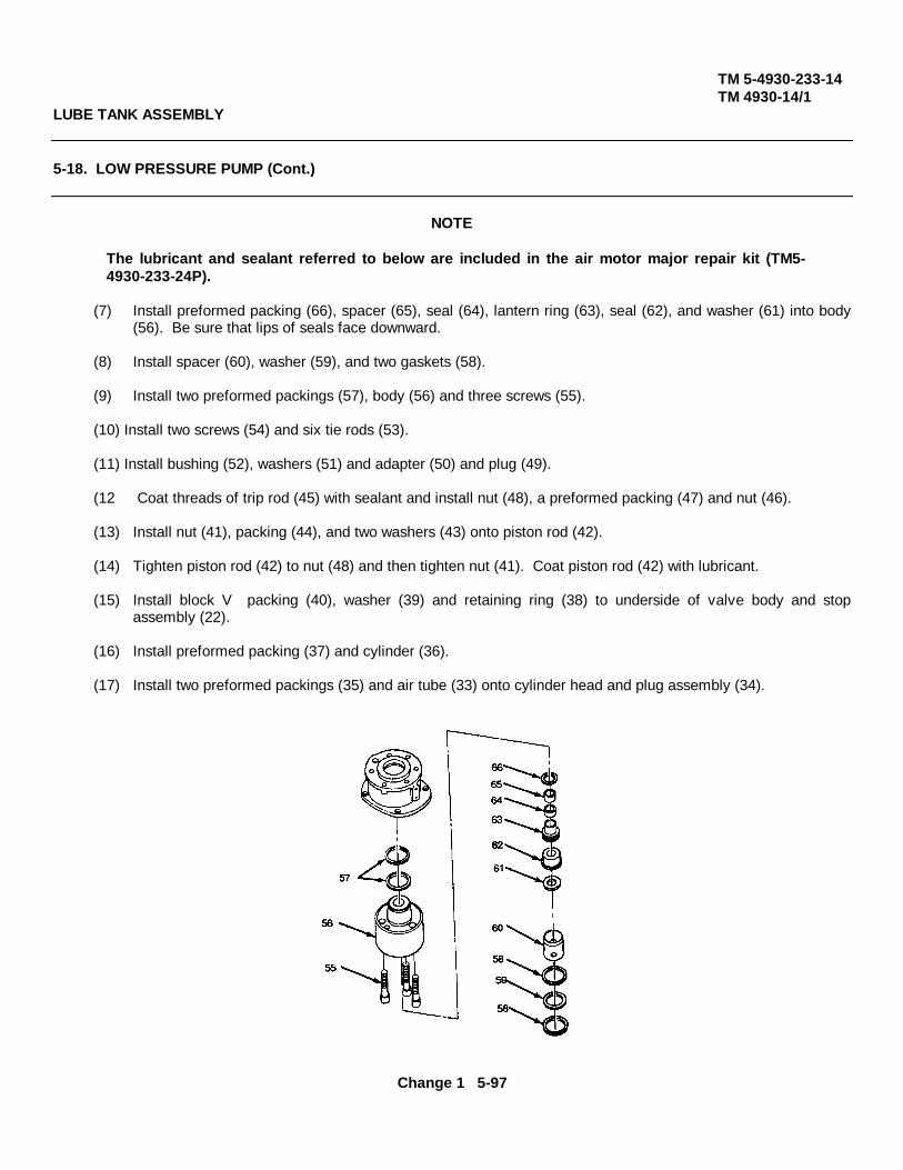
TM 5-4930-233-14TM 4930-14/1
LUBE TANK ASSEMBLY
5-18. LOW PRESSURE PUMP (Cont.)
NOTE
The lubricant and sealant referred to below are included in the air motor major repair kit (TM5-4930-233-24P).
(7) Install preformed packing (66), spacer (65), seal (64), lantern ring (63), seal (62), and washer (61) into body(56). Be sure that lips of seals face downward.
(8) Install spacer (60), washer (59), and two gaskets (58).
(9) Install two preformed packings (57), body (56) and three screws (55).
(10) Install two screws (54) and six tie rods (53).
(11) Install bushing (52), washers (51) and adapter (50) and plug (49).
(12 Coat threads of trip rod (45) with sealant and install nut (48), a preformed packing (47) and nut (46).
(13) Install nut (41), packing (44), and two washers (43) onto piston rod (42).
(14) Tighten piston rod (42) to nut (48) and then tighten nut (41). Coat piston rod (42) with lubricant.
(15) Install block V packing (40), washer (39) and retaining ring (38) to underside of valve body and stopassembly (22).
(16) Install preformed packing (37) and cylinder (36).
(17) Install two preformed packings (35) and air tube (33) onto cylinder head and plug assembly (34).
Change 1 5-97

TM 5-4930-233-14TM 4930-14/1
5-98
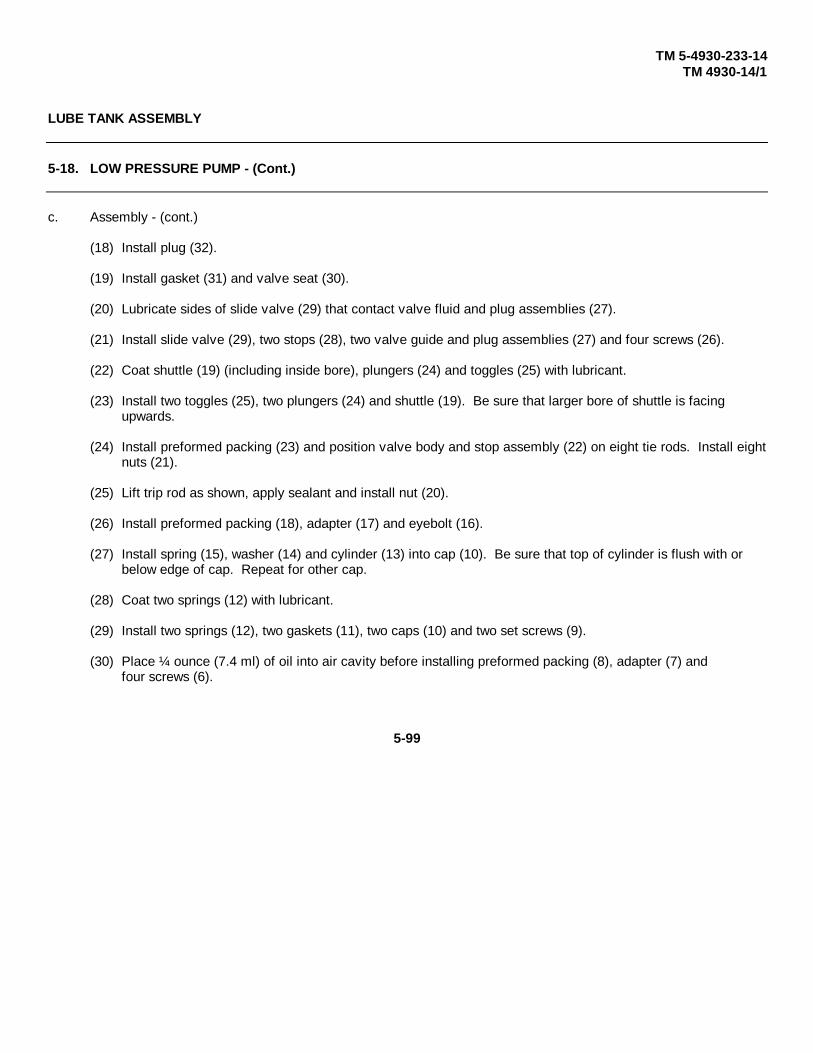
TM 5-4930-233-14TM 4930-14/1
LUBE TANK ASSEMBLY
5-18. LOW PRESSURE PUMP - (Cont.)
c. Assembly - (cont.)
(18) Install plug (32).
(19) Install gasket (31) and valve seat (30).
(20) Lubricate sides of slide valve (29) that contact valve fluid and plug assemblies (27).
(21) Install slide valve (29), two stops (28), two valve guide and plug assemblies (27) and four screws (26).
(22) Coat shuttle (19) (including inside bore), plungers (24) and toggles (25) with lubricant.
(23) Install two toggles (25), two plungers (24) and shuttle (19). Be sure that larger bore of shuttle is facing upwards.
(24) Install preformed packing (23) and position valve body and stop assembly (22) on eight tie rods. Install eightnuts (21).
(25) Lift trip rod as shown, apply sealant and install nut (20).
(26) Install preformed packing (18), adapter (17) and eyebolt (16).
(27) Install spring (15), washer (14) and cylinder (13) into cap (10). Be sure that top of cylinder is flush with or below edge of cap. Repeat for other cap.
(28) Coat two springs (12) with lubricant.
(29) Install two springs (12), two gaskets (11), two caps (10) and two set screws (9).
(30) Place ¼ ounce (7.4 ml) of oil into air cavity before installing preformed packing (8), adapter (7) andfour screws (6).
5-99
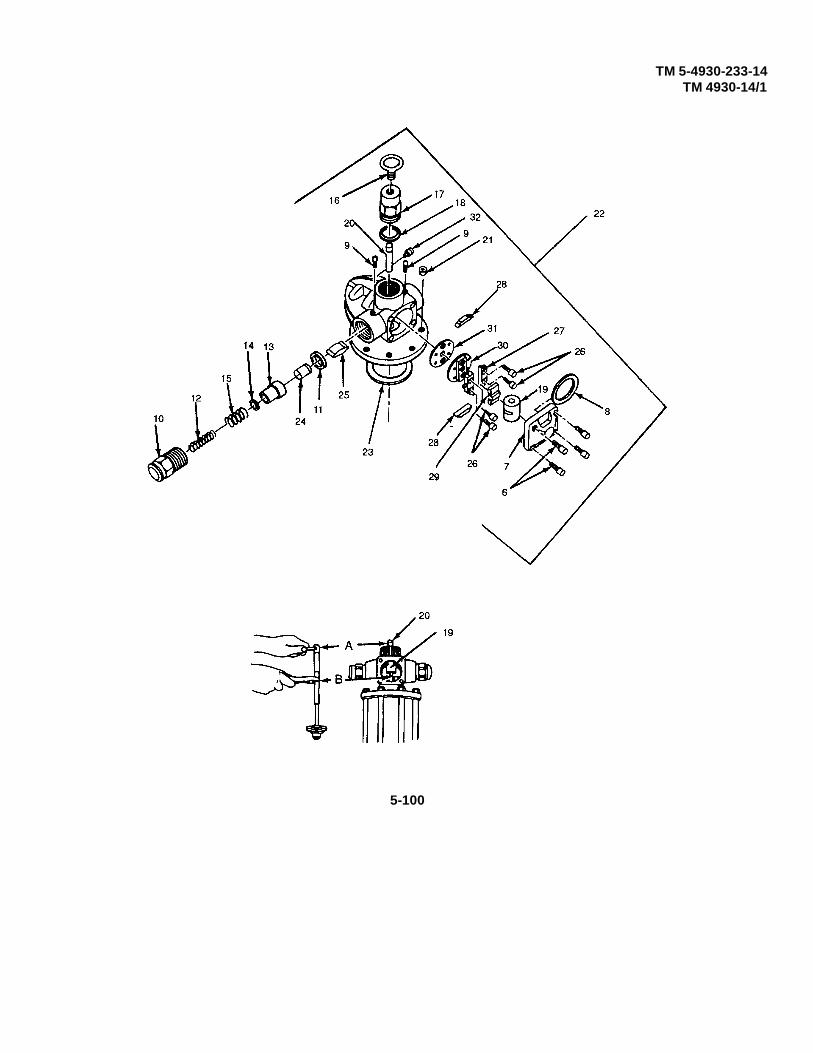
TM 5-4930-233-14TM 4930-14/1
5-100
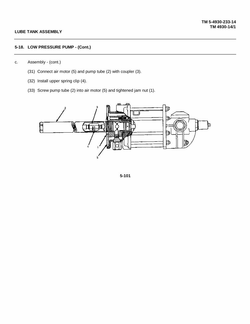
TM 5-4930-233-14TM 4930-14/1
LUBE TANK ASSEMBLY
5-18. LOW PRESSURE PUMP - (Cont.)
c. Assembly - (cont.)
(31) Connect air motor (5) and pump tube (2) with coupler (3).
(32) Install upper spring clip (4).
(33) Screw pump tube (2) into air motor (5) and tightened jam nut (1).
5-101
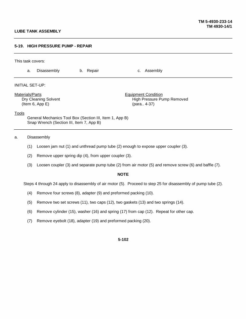
TM 5-4930-233-14TM 4930-14/1
LUBE TANK ASSEMBLY
5-19. HIGH PRESSURE PUMP - REPAIR
This task covers:
a. Disassembly b. Repair c. Assembly
INITIAL SET-UP:
Materials/Parts Equipment ConditionDry Cleaning Solvent High Pressure Pump Removed(Item 6, App E) (para.. 4-37)
ToolsGeneral Mechanics Tool Box (Section III, Item 1, App B)Snap Wrench (Section III, Item 7, App B)
a. Disassembly
(1) Loosen jam nut (1) and unthread pump tube (2) enough to expose upper coupler (3).
(2) Remove upper spring dip (4), from upper coupler (3).
(3) Loosen coupler (3) and separate pump tube (2) from air motor (5) and remove screw (6) and baffle (7).
NOTE
Steps 4 through 24 apply to disassembly of air motor (5). Proceed to step 25 for disassembly of pump tube (2).
(4) Remove four screws (8), adapter (9) and preformed packing (10).
(5) Remove two set screws (11), two caps (12), two gaskets (13) and two springs (14).
(6) Remove cylinder (15), washer (16) and spring (17) from cap (12). Repeat for other cap.
(7) Remove eyebolt (18), adapter (19) and preformed packing (20).
5-102
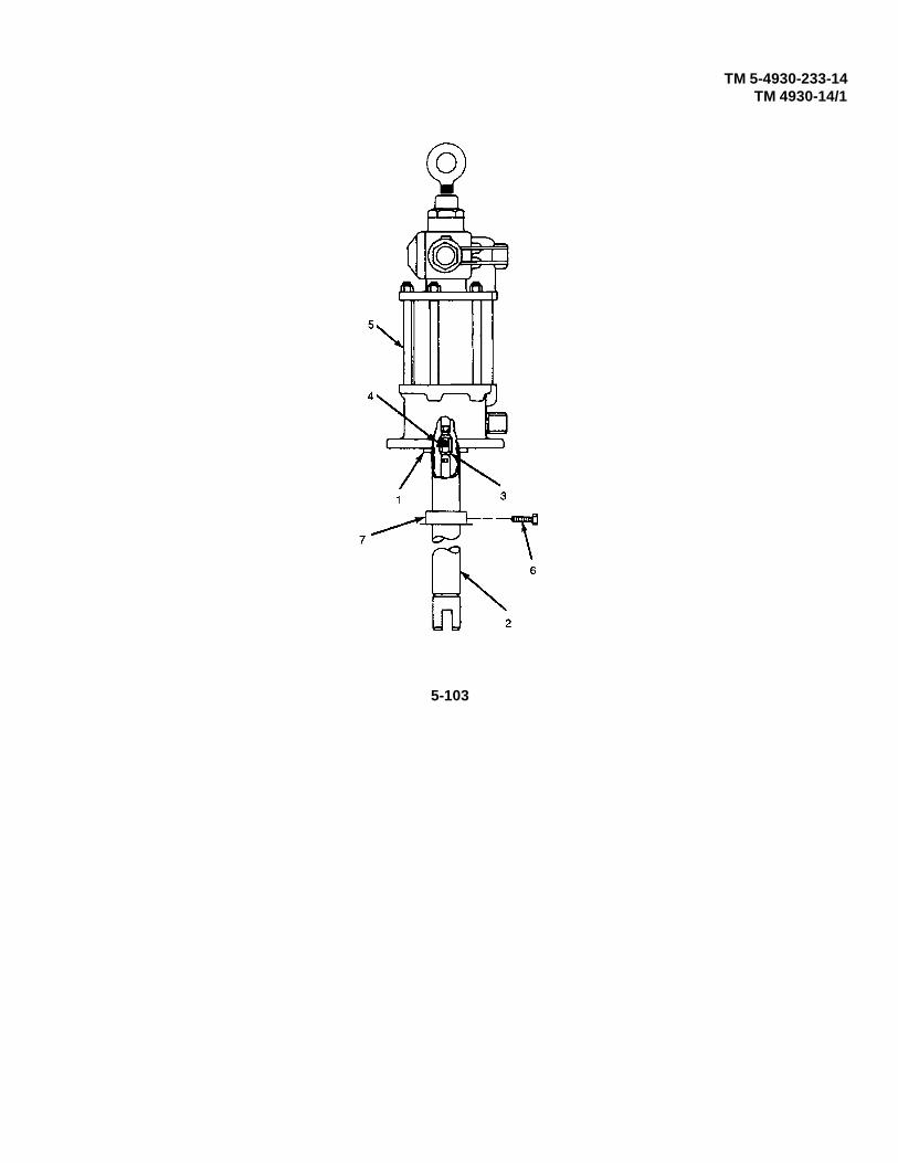
TM 5-4930-233-14TM 4930-14/1
5-103

TM 5-4930-233-14TM 4930-14/1
LUBE TANK ASSEMBLY
5-19. HIGH PRESSURE PUMP - REPAIR
a. Disassembly - (cont.)
CAUTION
Do not scratch trip rod. This can lead to equipment damage and unnecessary failure.
(8) Lift shuttle (21) and secure inside the motor assembly as shown. Remove nut (22).
(9) Remove five nuts (23) and lift valve body and stop assembly (24) off of tie rods. Remove preformed packing (25).
(10) Remove shuttle (21), two plungers (26) and two toggles (27).
(11) Remove four screws (28), two valve guide and plug assemblies (29), two stops (30) and slide valve (31).
CAUTION
Take care not to scratch valve side of seat during removal.
(12) Remove valve seat (32) and gasket (33).
(13) Remove plug (34).
5-104

TM 10-4930-233-14TM 4930-14/1
5-105

TM 10-4930-233-14TM 4930-14/1
LUBE TANK ASSEMBLY
5-19. HIGH PRESSURE PUMP - REPAIR
a. Disassembly - (cont.)
(14) Pull air tube (35) from cylinder head and plug assembly (36) and remove two preformed packings (37).
(15) Lift out cylinder (38) and remove preformed packing (39).
(16) Remove retaining ring (40), washer (41) and block v packing (42) from underside of valve body and stop assembly (24).
(17) Loosen nut (43) and remove piston rod (44).
(18) Secure trip rod (47) and remove nut (48), preformed packing (49) and nut (50).
(19) Remove plug (51), adapter (52), washer (53), and bushing (54).
(20) Remove six tie rods (55) and two screws (56).
(21) Remove three screws (57), body (58) and two preformed packings (59).
(22) Remove two gaskets (60), washers (61) and spacer (62).
(23) Push out through bottom of body (58), washer (63), seal (64), lantern ring (65), seal (66), spacer (67) and preformed packing (68).
Change 1 5-106

TM 5-4930-233-14TM 4930-14/1
5-107

TM 5-4930-233-14TM 4930-14/1
LUBE TANK ASSEMBLY
5-19. HIGH PRESSURE PUMP - REPAIR - (Cont.)
a. Disassembly - (cont.)
CAUTION
For initial disassembly take care not to damage adapter (71) when unthreading.Adapter threads are coated with sealant.
(24) Remove lower spring clip (69), and upper coupler (3) from rod (70).
(25) Unthread adapter (71) and pull free from assembly tube (72).
(26) Unthread primer body (73), and remove stop nut (74), plate (75), valve seat (76), gasket (77), valve body(78), three packings (79), screw (80) and guide washer (81).
(27) Remove lower spring clip (82) from lower coupler (83) and unthread piston and cylinder assembly (84).
(28) Pull tube (72) loose from piston and cylinder assembly and remove two gaskets (85).
(29) Pull adapter (71) up over primer rod (86) to expose roll pin (87).
(30) Drive out roll pin (87) and remove adapter (88), gasket (89), ball (90), spring (91) and spring retainer (92).
5-108
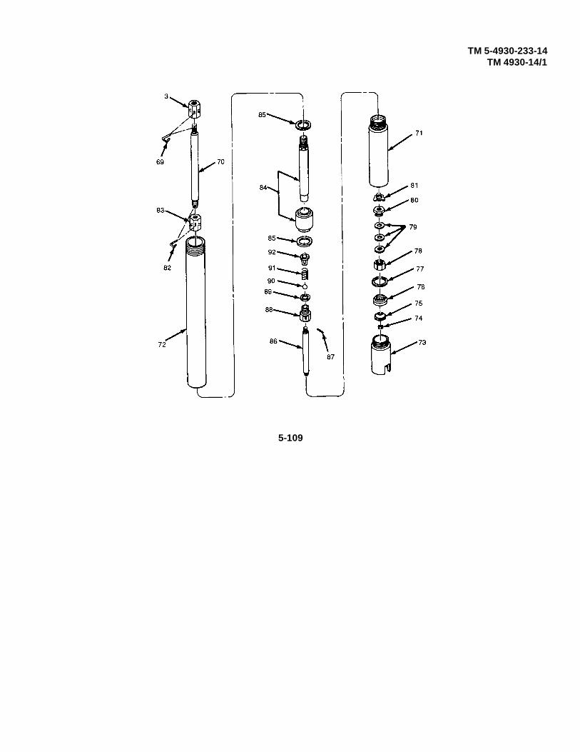
TM 5-4930-233-14TM 4930-14/1
5-109
TM 5-4930-233-14TM 4930-14/1
LUBE TANK ASSEMBLY
5-19. HIGH PRESSURE PUMP - REPAIR - (Cont.)
b. Repair
WARNING
Clean all parts in a well ventilated area. Avoid inhaling solventfumes and prolonged exposure of the skin to cleaning solvent.Failure to do so can cause severe injury or death. Do not use nearflame or excessive heat. Flash point of solvent is 100° F to 138°F(38°C to 59°C).
(1) Clean all parts with dry cleaning solvent.
(2) Discard and replace all gaskets and packings.
(3) Inspect and replace any worn or damaged parts.
(4) Inspect threaded surfaces for damage. Replace if defective.
(5) Inspect pump rods and tubes for cracks, breaks or other defects which should prevent proper operation.
(6) Inspect valve and valve seats for damage or wear. Replace as required.
c. Assembly
NOTE
Steps 1 through 8 apply to assembly of pump tube (2). Proceed tostep 9 for assembly of air motor (5). Go to step 34 for pump tubeand air motor assembly, together.
(1) Install spring retainer (92), spring (91), ball (90), gasket (89) and adapter (88). Drive in new roll pin (87).
(2) Slide adapter (71) over primer rod (86).
(3) Install two gaskets (85) and slide tube (72) onto piston and cylinder assembly (84).
(4) Connect piston and cylinder assembly (84) to rod (70) with lower coupler (83) and spring clip (82).
(5) Install guide washer (81), screw (80), three packings (79), valve body (78), gasket (77), valve seat (76), plate(75) and stop nut (74).
5-110
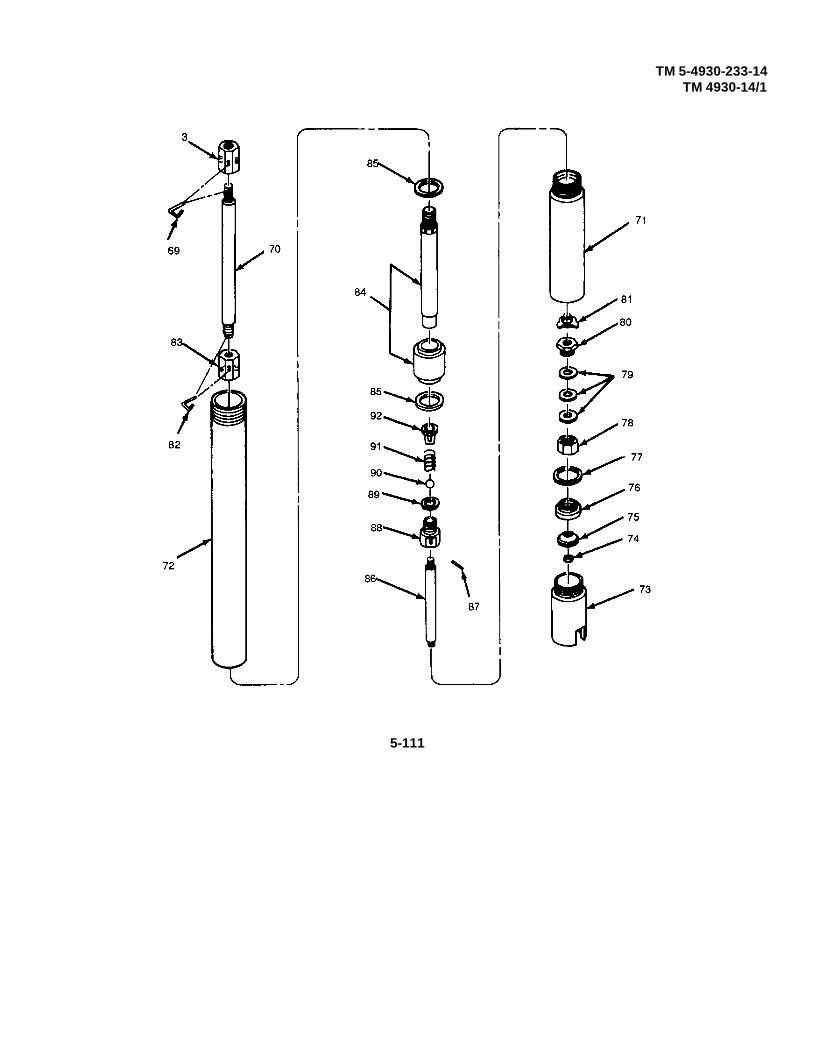
TM 5-4930-233-14TM 4930-14/1
5-111

TM 5-4930-233-14TM 4930-14/1
LUBE TANK ASSEMBLY
5-19. HIGH PRESSURE PUMP - REPAIR - (Con t.)
c. Assembly - (cont.)
(6) Install primer body (73).
(7) Connect assembly tube (72) to adapter (71).
(8) Install upper couplet (3) and spring clip (69).
NOTE
The lubricant and sealant referred to below are included in the air motor major repairkit (TM 5-4930-233-24P).
(9) Coat all packings and preformed packings with lubricant.
(10) Install preformed packing (68), spacer (67), seal (66), lantern ring (65), seal (64), washer (63) into body (58).Be sure lips of seals face downward.
(11) Install spacer (62), washer (61), and two gaskets (60).
(12) Install two preformed packings (59), body (58) and three screws (57).
5-112
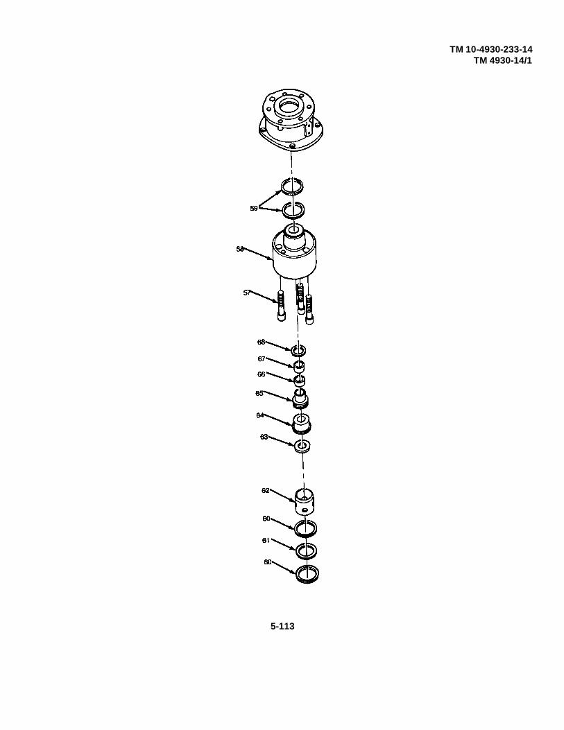
TM 10-4930-233-14TM 4930-14/1
5-113

TM 10-4930-233-14TM 4930-14/1
LUBE TANK ASSEMBLY
5-19. HIGH PRESSURE PUMP - REPAIR - (Cont.)
c. Assembly - (cont.)
(13) Install two screws (56) and six tie rods (55).
(14) Install bushing (54), washer (53) and adapter (52) and plug (51).
(15) Coat threads of trip rod (47) with sealant and install nut (50), and preformed packing (49) and nut (48).
(16) Install nut (43), packing (46) and two washers (45) onto piston rod (44).
(17) Tighten piston rod (44) to nut (50) and then tighten nut (43). Coat piston rod (44) with lubricant.
(18) Install block “v" packing (42), washer (41) and retaining ring (40) to underside of valve body and stop assembly (24).
(19) Install preformed packing (39) and cylinder (38).
(20) Install two preformed packings (37) and air tube (3) onto cylinder head and plug assembly (36).
Change 1 5-114
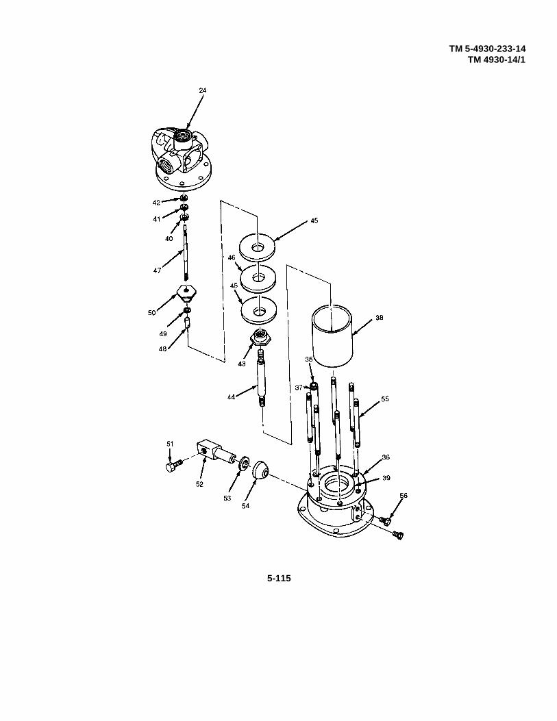
TM 5-4930-233-14TM 4930-14/1
5-115

TM 5-4930-233-14TM 4930-14/1
LUBE TANK ASSEMBLY
5-19. HIGH PRESSURE PUMP - REPAIR - (Cont.)
c. Assembly- (cont.)
(21) Install plug (34).
(22) Install gasket (33) and valve seat (32).
(23) Lubricate sides of slide valve (31) that contact valve guide and plug assemblies (29).
(24) Install slide valve (31), two stops (30), two valve guide and plug assemblies (29) and four screws (28).
(25) Coat shuttle (21) (including inside bore), plungers (26) and toggles (27) with lubricant.
(26) Install two toggles (27), two plungers (26) and shuttle (21). Be sure that larger bore of shuttle is facing upwards.
(27) Install preformed packing (25) and position valve body and stop assembly (24) on five tie rods. Install five nuts (23).
(28) Lift trip rod as shown and install nut (22).
(29) Install preformed packing (20), adapter (19) and eyebolt (18).
(30) Install spring (17), washer (16) and cylinder (15) into cap (12). Be sure that top of cylinder is flush with or below edge of cap. Repeat for other cap.
(31) Coat four springs (14) with lubricant.
(32) Install four springs (14), two gaskets (133), two caps (12) and two set screws (11).
(33) Place ¼ ounce (7.4 ml) of oil into air cavity before installing preformed packing (10), adapter (9) and four screws (8).
5-116

TM 5-4930-233-14TM 4930-14/1
5-117

TM 5-4930-233-14TM 4930-14/1
LUBE TANK ASSEMBLY
5-19. HIGH PRESSURE PUMP - REPAIR - (Cont.)
c. Assembly - (cont.)
(34) Install baffle (7), screw (6) on pump tube (2), connect air motor (5) and pump tube (2) with couplet (3).
(35) Install upper spring clip (4).
(36) Screw pump tube (2) into air motor (5) and tighten jam nut (1).
5-118

TM 5-4930-233-14TM 4930-14/1
LUBE TANK ASSEMBLY
5-20. LUBE TANK- REPAIR
This task covers:
Repair
INITIAL SET-UP:
Materials/Parts Equipment ConditionDry Cleaning Solvent Lube Tank Removed(Item 6, App E) (para.. 4-38)
ToolsGeneral Mechanics Tool Box (Section III, Item 1, App B)Electric Welder (Section III, Item 5, App B)
Repair
WARNING
Clean all parts in a well ventilated area. Avoid inhaling solventfumes and prolonged exposure of the skin to cleaning solvent.Failure to do so can cause severe injury or death. Do not use nearflame or excessive heat. Flash point of solvent is 100° F to 138°F(38°C to 59°C).
(1) Flush out each of the three lubricant compartments in the tank using dry cleaning solvent.
(2) Inspect tank for cracks, broken welds and damage.
(3) Repair cracks by welding if practical.
(4) Repair broken welds.
(5) Straighten dents and tap damaged threads.
5-119

TM 5-4930-233-14TM 4930-14/1
WINTERIZATION ASSEMBLY
5-21. CONTROL BOX- REPAIR
This task covers:
a. Disassembly b. Repair c. Assembly
INITIAL SET-UP:
Equipment Condition ToolsControl Box Removed General Mechanics Tool Box(para. 4-40) (Section III, Item 1, App B)
Multimeter(Section III, Item 4, App B)
a. Disassembly
(1) Remove two screws (1) and case assembly (2).
(2) Remove two nuts (3), two screws (4) and two nuts (5) from case.
(3) Tag and disconnect all electrical leads and jumpers.
(4) Remove two nuts (6), two lockwashers (7) and two switches (8).
(5) Remove lens assembly (9), bulb (10), nut (11), washer (12), lamp assembly (13) and switch panel (14).
(6) Remove four screws (15) and receptacle assembly (16).
(7) Remove two screws (17) and bracket (18).
(8) Remove two screws (19), two washers (20) and circuit breaker (21).
(9) Remove grommet (22) from panel (23).
b. Repair
(1) Test circuit breaker for continuity. If no continuity is present, replace.
(2) Inspect all wiring for cuts, deterioration or damage. Replace if defective.
(3) Check switches for correct operation. Replace if damaged or if contact is not positive during switch actions.
(4) Replace case if damaged.
(5) Replace switch panel if illegible.
5-120

TM 5-4930-233-14TM 4930-14/1
WINTERIZATION ASSEMBLY
5-21. CONTROL BOX- REPAIR
c. Assembly
(1) Install grommet (22) into panel (23).
(2) Install circuit breaker (21), two washers (20) and two screws (19).
(3) Install bracket (18) with two screws (17).
(4) Install receptacle assembly (16) with four screws (15).
(5) Install switch panel (14), lamp assembly (13), washer (12), nut (11), bulb (10) and lens assembly (9).
(6) Install two switches (8), two lockwashers (7) and two nuts (6 ).
(7) Connect all electrical leads and jumpers. Remove tags.
(8) Install two nuts (5), two screws (4) and two nuts (3).
(9) Install case assembly (2) with two screws (1).
5-121

TM 5-4930-233-14TM 4930-14/1
FRAME AND SKID ASSEMBLY
5-22. FRAME AND SKID ASSEMBLY - INSPECT/REPAIR
This task covers:
a. Repair
INITIAL SET-UP:
References NOTETM 43-0139 Painting This procedure does not require the removalInstructions for field use of any components except those that will
provide access to the area to be repaired.Tools
General Mechanics Tool Box(Section III, Item 1, App B)Electric Welder(Section III, Item 5, App B)
Repair
NOTEIf access cannot be gained to any area requiring repair withoutremoval of the enclosure, notify general support maintenance.
(1) Inspect a frame (1) and skid (2) assembly for corrosion.
(2) If corrosion is present, remove using with brush and touch up paint (TM 43-0139).
(3) Inspect all welded joints for cracks. Repair welds as required.
5-122

TM 5-4930-233-14TM 4930-14/1
5-123

TM 5-4930-233-14TM 4930-14/1
AIR BRAKE ASSEMBLY
5-23. POWER CLUSTER - REPLACE/REPAIR
This task covers:
a. Removal b. Disassembly c. Repair d. Assemblye. Installation
INITIAL SET-UP:
Materials/Parts NOTEDry Cleaning Solvent No repair is authorized for the master brake(Item 6, App E) cylinder. Replace if damaged.
ToolsGeneral Mechanics Tool Box(Section III, Item 1, App B)
a. Removal
(1) Vent air brake pressure completely by opening valve (1). Close valve.
5-124
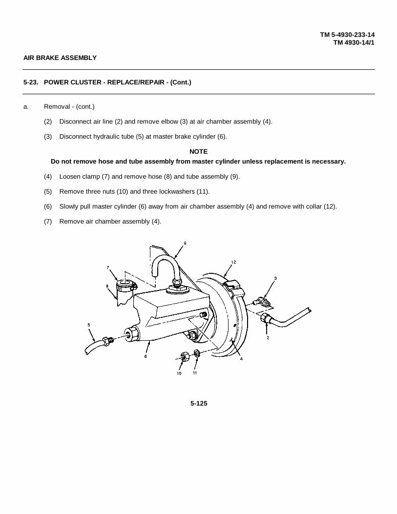
TM 5-4930-233-14TM 4930-14/1
AIR BRAKE ASSEMBLY
5-23. POWER CLUSTER - REPLACE/REPAIR - (Cont.)
a. Removal - (cont.)
(2) Disconnect air line (2) and remove elbow (3) at air chamber assembly (4).
(3) Disconnect hydraulic tube (5) at master brake cylinder (6).
NOTEDo not remove hose and tube assembly from master cylinder unless replacement is necessary.
(4) Loosen clamp (7) and remove hose (8) and tube assembly (9).
(5) Remove three nuts (10) and three lockwashers (11).
(6) Slowly pull master cylinder (6) away from air chamber assembly (4) and remove with collar (12).
(7) Remove air chamber assembly (4).
5-125
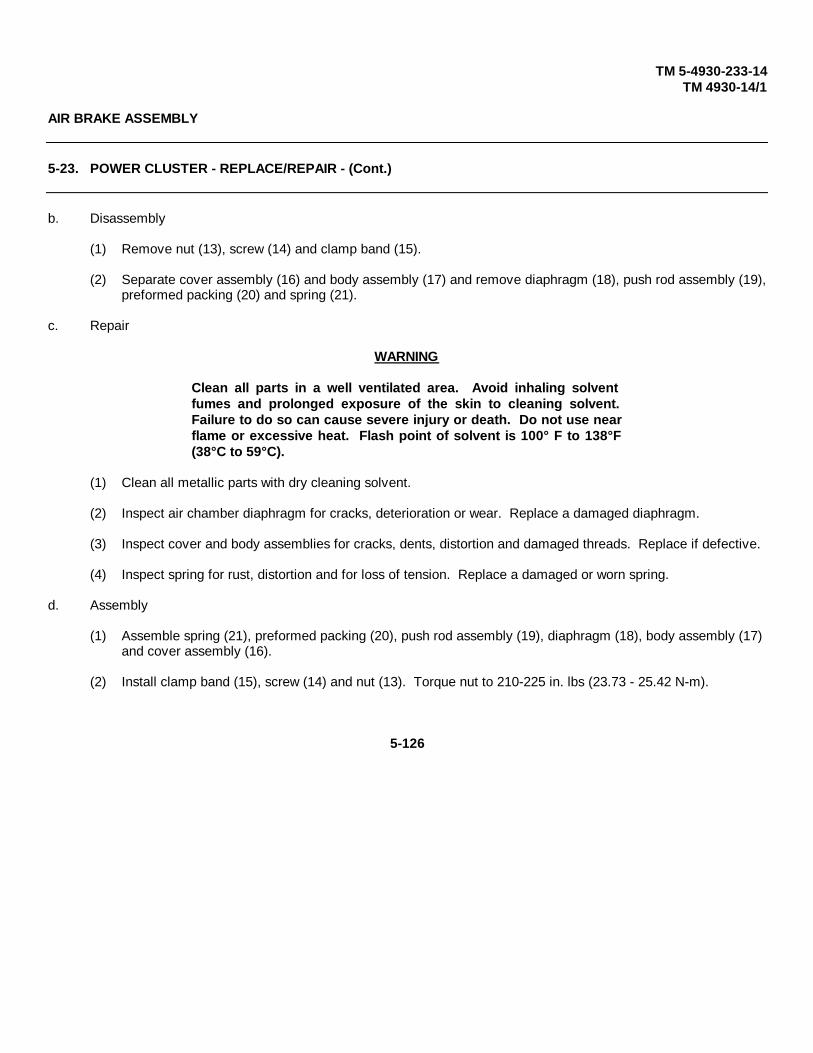
TM 5-4930-233-14TM 4930-14/1
AIR BRAKE ASSEMBLY
5-23. POWER CLUSTER - REPLACE/REPAIR - (Cont.)
b. Disassembly
(1) Remove nut (13), screw (14) and clamp band (15).
(2) Separate cover assembly (16) and body assembly (17) and remove diaphragm (18), push rod assembly (19),preformed packing (20) and spring (21).
c. Repair
WARNING
Clean all parts in a well ventilated area. Avoid inhaling solventfumes and prolonged exposure of the skin to cleaning solvent.Failure to do so can cause severe injury or death. Do not use nearflame or excessive heat. Flash point of solvent is 100° F to 138°F(38°C to 59°C).
(1) Clean all metallic parts with dry cleaning solvent.
(2) Inspect air chamber diaphragm for cracks, deterioration or wear. Replace a damaged diaphragm.
(3) Inspect cover and body assemblies for cracks, dents, distortion and damaged threads. Replace if defective.
(4) Inspect spring for rust, distortion and for loss of tension. Replace a damaged or worn spring.
d. Assembly
(1) Assemble spring (21), preformed packing (20), push rod assembly (19), diaphragm (18), body assembly (17) and cover assembly (16).
(2) Install clamp band (15), screw (14) and nut (13). Torque nut to 210-225 in. lbs (23.73 - 25.42 N-m).
5-126

TM 5-4930-233-14TM 4930-14/1
5-127

TM 5-4930-233-14TM 4930-14/1
AIR BRAKE ASSEMBLY
5-23. POWER CLUSTER - REPLACE/REPAIR - (Cont.)
e. Installation
(1) Install air chamber assembly (4), collar (12) and master cylinder (6).
(2) Install three lockwashers (11), and three nuts (10). Torque nut to 25-31 ft. lbs (33.9 - 42.03 N-m).
(3) Install tube assembly (9). Tube assembly nut should be hand tightened.
(4) Install hose (8) and clamp (7). Torque clamp to 30-50 ft. lbs (40.68-67.8 N-m).
(5) Connect hydraulic tube (5) at master brake cylinder.
(6) Install elbow (3) and connect air line (2).
(7) Bleed and adjust brakes (para. 4-58).
5-128

TM 5-4930-233-14TM 4930-14/1
AXLE ASSEMBLY
5-24. AXLE ASSEMBLY - REPLACEThis task covers:
a. Removal b. Installation
INITIAL SET-UP:
Equipment Condition ToolsEnclosure and Skid Assembly General Mechanics Tool BoxRemoved (para 5-2) (Section III, Item 1, App B)
a. Removal
(1) Disconnect trailer air brake lines from towing vehicle.
(2) Vent all air brake pressure by opening valve (1). Close valve when complete.
5-129
TM 5-4930-233-14TM 4930-14/1
AXLE ASSEMBLY
5-24. AXLE ASSEMBLY - REPLACE - (Cont.)
a. Removal - (cont.)
WARNING
Any time the trailer is jacked up, ensure jackstands are used to avoid personal injury.
(3) Jack trailer up until both wheels are off the ground and securely blocked in all four corners.
(4) Block axle securely at both ends.
(5) Remove both tire and wheels (para 4-57).
(6) Disconnect hydraulic brake line (2).
(7) Remove four locknuts (3) and four screws (4). Note location of bolts for installation purpose.
(8) Slide lower axle assembly (5) out from under trailer.
b. Installation
(1) Position axle assembly (5) under trailer and install four screws (4) and four locknuts (3).
(2) Connect hydraulic brake line (2).
(3) Install both tires and wheels (para 4-57).
(4) Remove blocking from underneath axle.
(5) Bleed brake system (para 4-58).
(6) Remove blocking and lower trailer to the ground.
5-130

TM 5-4930-233-14TM 4930-14/1
5-131

TM 5-4930-233-14TM 4930-14/1
FRAME ASSEMBLY
5-25. FRAME ASSEMBLY - REPLACEThis task covers:
Replacement
INITIAL SET-UP:
ToolsGeneral Mechanics Tool Box (Section III, Item 1, App B)
Replacement
NOTE
The following items must be removed from the trailer frame being replaced andinstalled on the new one.
(1) Enclosure and skid assembly (para 5-2).
(2) Trailer components (para 4-46).
(3) Air Brake components (para 4-47 thru 4-52).
(4) Power Cluster (para 5-23).
(5) Trailer Electrical Components (para 4-53 thru 4-56).
(6) Axle Assembly (para 5-24).
5-132

TM 10-4930-233-14TM 4930-14/1
Chapter 6
Section I. PMCS AND TROUBLESHOOTING PROCEDURES
There are no General Support PMCS or troubleshooting procedures.
Section II. GENERAL SUPPORT MAINTENANCE INSTRUCTIONS
SKID SUB ASSEMBLY
6-1. FUEL TANK - REPAIR
This task covers:
Repair
INITIAL SET-UP:
Materials/Parts Equipment ConditionDry Cleaning Solvent Fuel Tank Removed (para 4-16)(Item 6, App E) Fuel Tank Disassembled (para NO TAG)
ToolsGeneral Mechanics Tool Box (Section III, Item 1, App B)Electric Welder (Section III, Item 5, App B)
WARNING
Before performing any work on fuel tank, insure that all gasoline and gasolinevapors have been purged. If not, an explosion can result, causing death or severeinjury.
Repair
WARNING
Clean all parts in a well ventilated area. Avoid inhaling solvent fumes andprolonged exposure of the skin to cleaning solvent. Failure to do so can causesevere injury or death. Do not use near flame or excessive heat. Flash point ofsolvent is 1000F to 1380F (380C to 59°C).
(1) Flush out tank completely with dry cleaning solvent.
(2) Dry out tank thoroughly.
(3) Inspect fuel tank for large cracks, severe dents or damage.
Change 1 6-1

TM 10-4930-233-14TM 4930-14/1
SKID SUB ASSEMBLY6-1. FUEL TANK - REPAIR - (Cont.)
Repair - (cont.)
(4) If damage is such that repair is not feasible, replace tank.
(5) If dents are minor, straighten out as required.
(6) If welds are damaged or cracks are present, weld as needed.
(7) If threads are damaged, retap as necessary.
6-2 Change 1

TM 10-4930-233-14TM 4930-14/1
FRAME AND SKID ASSEMBLY6-2. FRAME AND SKID ASSEMBLY - REPLACE/REPAIR
This task covers:
a. Replace b. Repair
INITIAL SET-UP:
References Equipment Conditions PageTM 43-0139 Enclosure and skid assemblyPainting instructions removed (para 5-2)for field use Enclosure removed (para 4-11)
ToolsGeneral Mechanics Tool Box(Section III, Item 1, App B) Materials/PartsWelder (Section III, Item 1, App B) Wire Brush (Item 15, App E)
a. Replace
NOTE
A frame and skid assembly does not have to be removed to be repaired. Thefollowing items must be removed from the A frame and skid assembly beingreplaced, and installed on the new one.
(1) Skid sub assembly components removed (para 4-15 and 4-16).
(2) Reel cabinet and components removed (para 4-17 thru 4-21).
(3) Air compressor assembly components removed (para 4-29 thru 4-31).
(4) Lube tank assembly components (para 4-35 thru 4-38).
(5) Winterization assembly components removed (para 4-39 and 4-43).
(6) Lube and pneumatic piping removed (para 4-44 and 4-45).
6-3

TM 10-4930-233-14TM 4930-14/1
FRAME AND SKID ASSEMBLY
6-2. FRAME AND SKID ASSEMBLY - REPLACE/REPAIR - (Cont.)
b. Repair
NOTE
Remove slid sub assembly components as required to give full access to areaneeding repair.
(1) Inspect A frame (1) and skid (2) assembly for corrosion.
(2) If corrosion is present, remove using wire brush and touch up paint (TM 43-0139).
(3) Inspect all welded joints for cracks. Repair welds as required.
(4) Straighten any dents and repair damage as necessary.
6-4 Change 1
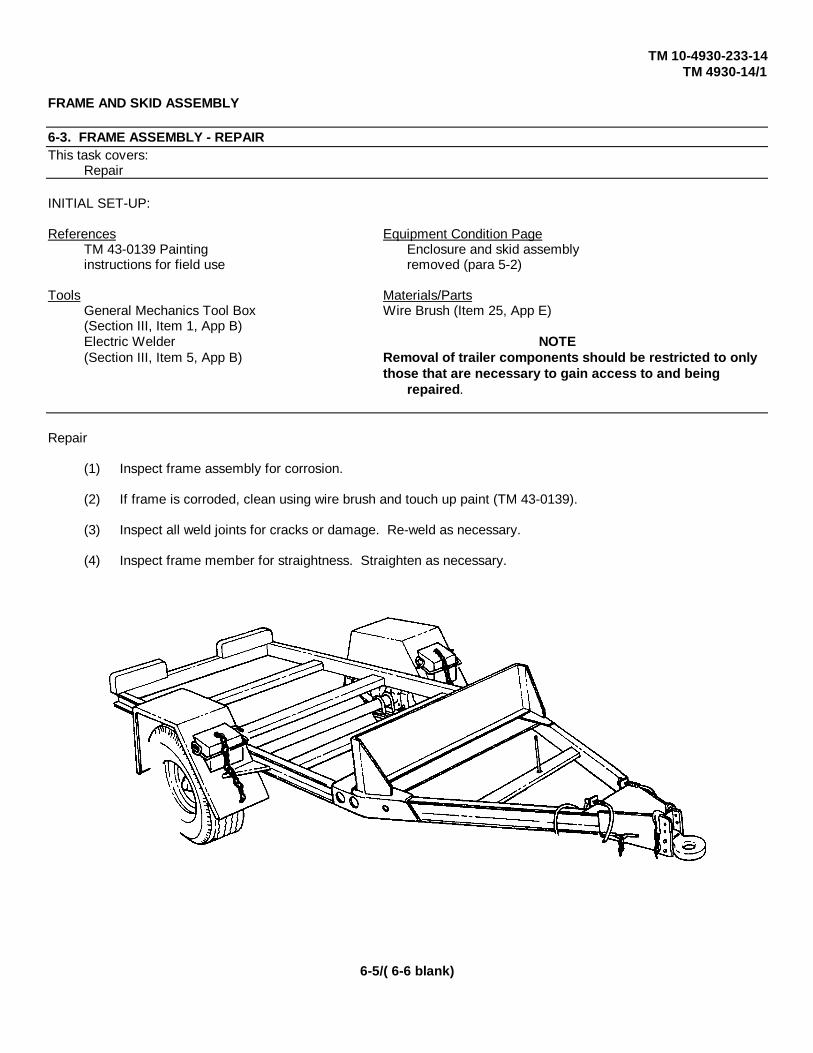
TM 10-4930-233-14TM 4930-14/1
FRAME AND SKID ASSEMBLY
6-3. FRAME ASSEMBLY - REPAIRThis task covers:
Repair
INITIAL SET-UP:
References Equipment Condition PageTM 43-0139 Painting Enclosure and skid assemblyinstructions for field use removed (para 5-2)
Tools Materials/PartsGeneral Mechanics Tool Box Wire Brush (Item 25, App E)(Section III, Item 1, App B)Electric Welder NOTE(Section III, Item 5, App B) Removal of trailer components should be restricted to only
those that are necessary to gain access to and being repaired.
Repair
(1) Inspect frame assembly for corrosion.
(2) If frame is corroded, clean using wire brush and touch up paint (TM 43-0139).
(3) Inspect all weld joints for cracks or damage. Re-weld as necessary.
(4) Inspect frame member for straightness. Straighten as necessary.
6-5/( 6-6 blank)

TM 5-4930-233-14TM 4930-14/1
Appendix A
REFERENCES
A-1. SCOPE
This appendix lists all forms, field manuals, technical manuals and miscellaneous publications referenced in this manual.
A-2. FORMS
Recommended Changes to DA Publications ..............................................DA Form 2028-2
Equipment Inspection and Maintenance Work Sheet .................................DA Form 2404
Quality Deficiency Report ..........................................................................DA Form 368
A-3. FIELD MANUALS
Operation and Maintenance of Ordnance Material in Cold Weather ...........FM 9-207
Manual for the Wheeled Vehicle Driver ......................................................FM 21-305
A-4. MANUALS
Hand Portable Fire Extinguishers Approved for Army Users ......................TB 5-4200-200-10
Inspection and Test of Air and Other Gas Compressors .............................TB 43-0151
The Army Maintenance Management System
(TAMMS)....................................................................................................DA PAM 738-750
Equipment Record Procedures (Marine Corps) ..........................................TM 4700-15/1E
Operator, Organizational, (Field)(Direct Support and General Support)and Depot Level Maintenance Manual:Engine, Gasoline, 6 HP (Military StandardModels DOD 4A032-1) (NSN 2805-01-776-0483) and (Model 4A032-2) (2805-00-066-7512) and (Model 4A032-3) (2805-01 -139-0596) .............................................................................................TM 9-2805-262-14
A-1

TM 5-4930-233-14TM 4930-14/1
Organizational, Intermediate (Field)(Direct and General Support) and DepotMaintenance Repair Parts and SpecialTools List for Engine, Gasoline, 6 HP,Military Standard Models: DOD Model4A032-1 (NSN 2805-00-776-8403), DOD Model4A032-2 (2805-00-066-7512) and Model4A032-3 (2805-01-139-0596) .....................................................................TM 5-2805-203-24P
Care and Maintenance of AntifrictionBearings .....................................................................................................TM 9-214
Welding Theory and Application ................................................................TM 9-237
Organizational, Direct Support andGeneral Support Care, Maintenance andRepair of Pneumatic Tires and InnerTubes ........................................................................................................TM 9-2610-200-24
Operator's Organizational, Direct Supportand General Support Maintenance Manualfor Lead-Acid Storage Batteries: 4HN, 24V (NSN 6140-00-059-3526) MS75047-1; 2HN,12 V (6140-00-057-2563) MS35000-1; 6TN, 12V (6140-00-057-2554) MS35000-3 .............................................................TM 9-6140-200-14
Painting Instructions for Field Use ..............................................................TM 43-0139
Procedures for Destruction of Equipmentto Prevent Enemy Use ...............................................................................TM 750-244-3
Unit, Direct and General SupportRepair Parts and Special Tools List forLubrication and Servicing Unit, PowerOperated LST-178A-85 ..............................................................................TM 5-4930-233-24P(Army)...................................................................................................................TM 4930-24/2 (MC)
A-2

TM 5-4930-233-14TM 4930-14/1
Appendix B
MAINTENANCE ALLOCATION CHART
Section I. INTRODUCTION
B-1. GENERAL
a. This section provides a general explanation of all maintenance and repair functions authorized at variousmaintenance categories.
b. The Maintenance Allocation Chart (MAC) in Section II designates overall authority and responsibility for theperformance of maintenance functions on the identified end item or component. The application of the maintenancefunction to the end item or component will be consistent with the capacities and capabilities of the designatedmaintenance categories.
c. Section Illlists the tools and test equipment (both special tools and common tool sets) required for eachmaintenance function as referenced from Section II
d. Section IV contains supplemental instructions and explanatory notes for a particular maintenance function.
B-2. MAINTENANCE FUNCTIONS . Maintenance functions will be limited to and defined as follows:
a. Inspect. To determine the serviceability of an item by comparing its physical, mechanical, and/or electricalcharacteristics with established standards through examination (e.g., by sight, sound, or feel).
b. Test. To verify serviceability by measuring the mechanical, pneumatic, hydraulic, or electrical characteristicsof an item and comparing those characteristics with prescribed standards.
c. Service. Operations required periodically to keep an item in proper operating condition, i.e., to clean(includes decontaminate, when required), to preserve, to drain, to paint, or to replenish fuel, lubricants, chemical fluids,or gases.
d. Adjust. To maintain or regulate, within prescribed limits, by bringing into proper or exact position, or bysetting the operating characteristics to specified parameters.
e. Aline. To adjust specified variable elements of an item to bring about optimum or desired performance.f. Calibrate. To determine and cause corrections to be made or to be adjusted on instruments or test,
measuring, and diagnostic equipments used in precision measurement. Consists of comparisons of two instruments, oneof which is a certified standard of known accuracy, to detect and adjust any discrepancy in the accuracy of the instrumentbeing compared.
g. Remove/Install. To remove and install the same item when required to perform service or othermaintenance functions. Install may be the act of emplacing, seating, or fixing into position a spare, repair part, or module(component or assembly) in a manner to allow the proper functioning of an equipment or system.
h. Replace. To remove an unservicable item and install a serviceable counterpart in its place. "Replace" isauthorized by the MAC and is shown as the 3d position code of the SMR code.
B-1
TM 5-4930-233-14TM 4930-14/1
i. Repair. The application of maintenance services1, including fault location/troubleshooting2,removal/installation, and disassembly/assembly3 procedures, and maintenance actions4 to identify troubles and restoreserviceability to an item by correcting specific damage, fault, malfunction, or failure in a part, subassembly, module(component or assembly), end item, or system.
j. Overhaul. That maintenance effort (service/action) prescribed to restore an item to a completelyserviceable/operational condition as required by maintenance standards in appropriate technical publications (i.e.,DMWR). Overhaul is normally the highest degree of maintenance performed by the Army. Overhaul does not normallyreturn an item to like new condition.
k. Rebuild. Consists of those services/actions necessary for the restoration of unserviceable equipment to alike new condition in accordance with original manufacturing standards. Rebuild is the highest degree of materielmaintenance applied to Army equipment. The rebuild operation includes the act of returning to zero those agemeasurement (hours/miles, etc.) considered in classifying Army equipment/components.
B-3. EXPLANATION OF COLUMNS IN THE MAC, Section II
a. Column 1, Group Number. Column 1 lists functional group code numbers, the purpose of which is to identifymaintenance significant components, assemblies, subassemblies, and modules with the next higher assembly. End itemgroup number shall be"00."
b. Column 2, Component/Assembly. Column 2 contains the names of components, assemblies,subassemblies, and modules for which maintenance is authorized.
c. Column 3, Maintenance Function. Column 3 lists the functions to be performed on the item listed in Column2. (For detailed explanation of these functions, see paragraph B-2.)
d. Column 4, Maintenance Category. Column 4 specifies, by the listing of work time figures in the appropriatesubcolumn(s), the category of maintenance authorized to perform the function listed in Column 3. This figure representsthe active time required to perform that maintenance function at the indicated category of maintenance. If the number orcomplexity of the tasks within the listed maintenance function vary at different maintenance categories, appropriate worktime figures will be shown for each category. The work time figure represents the average time required to restore anitem (assembly, subassembly, component, module, end item, or system) to a serviceable condition under typical fieldoperating conditions. This time includes preparation time (including any necessary disassembly/assembly time),troubleshooting/fault location time, and quality assurance/quality control time in addition to the time required to performthe specific tasks identified for the maintenance functions authorized in the maintenance allocation chart. The symbol
1 Services - inspect, test, service, adjust, aline, calibrate, and/or replace.2 Fault locate/troubleshoot - The process of investigating and detecting the cause of equipment malfunctioning; the
act of isolating a fault within a system or unit under test (UUT).3 Disassemble/assemble - encompasses the step-by-step taking apart (or breakdown) of a spare/functional group
coded item to the level of its least componency identified as maintenance significant (i.e.. assigned an SMR code)for the category of maintenance under consideration.
4 Actions - welding, grinding, riveting, straightening, facing, remachining, and/or resurfacing.
B-2

TM 10-4930-233-14TM 4930-14/1
designations for the various maintenance categories are as follows:C Operator or crewO Unit MaintenanceF Direct Support MaintenanceH General Support MaintenanceL Specialized Repair Activity (SRA)D Depot Maintenance
e. Column 5, Tools and Equipment. Column 5 specifies, by code, those common tool sets (not individual tools)and special tools, TMDE, and support equipment required to perform the designated function.
f. Column 6, Remarks. This column shall, when applicable, contain a letter code, in alphabetic order, whichshall be keyed to the remarks contained in Section IV.B-4. EXPLANATION OF COLUMNS IN TOOL AND TEST EQUIPMENT REQUIREMENTS, Section III
a. Column 1, Reference Code. The tool and test equipment reference code correlates with a code used in theMAC, Section II, Column 5.
b. Column 2, Maintenance Category. The lowest category of maintenance authorized to use the tool or testequipment.
c. Column 3, Nomenclature. Name or identification of the tool or test equipment.d. Column 4, National Stock Number. The National Stock Number (NSN) of the tool or test equipment.e. Column 5, Tool Number. The Manufacturer's part number.
B-5. EXPLANATION OF COLUMNS IN REMARKS, Section IV.
a. Column 1, Reference Code. The code recorded in column 6, Section IIb. Column 2, Remarks. This column lists information pertinent to the maintenance function being performed as
indicated in the MAC, Section II
B-3
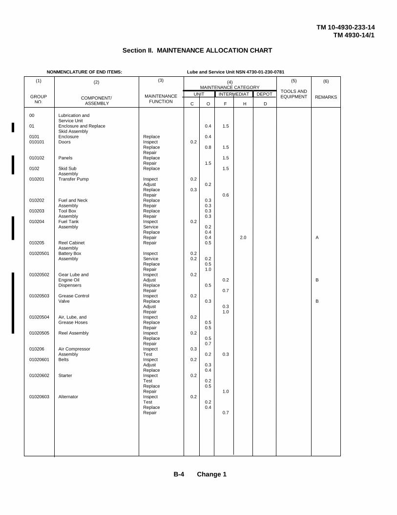
TM 10-4930-233-14TM 4930-14/1
Section II. MAINTENANCE ALLOCATION CHART
NONMENCLATURE OF END ITEMS: Lube and Service Unit NSN 4730-01-230-0781
00 Lubrication andService Unit
01 Enclosure and Replace 0.4 1.5Skid Assembly
0101 Enclosure Replace 0.4010101 Doors Inspect 0.2
Replace 0.8 1.5Repair
010102 Panels Replace 1.5Repair 1.5
0102 Skid Sub Replace 1.5Assembly
010201 Transfer Pump Inspect 0.2Adjust 0.2Replace 0.3Repair 0.6
010202 Fuel and Neck Replace 0.3Assembly Repair 0.3
010203 Tool Box Replace 0.3Assembly Repair 0.3
010204 Fuel Tank Inspect 0.2Assembly Service 0.2
Replace 0.4Repair 0.4 2.0 A
010205 Reel Cabinet Repair 0.5Assembly
01020501 Battery Box Inspect 0.2Assembly Service 0.2 0.2
Replace 0.5Repair 1.0
01020502 Gear Lube and Inspect 0.2Engine Oil Adjust 0.2 BDispensers Replace 0.5
Repair 0.701020503 Grease Control Inspect 0.2
Valve Replace 0.3 BAdjust 0.3Repair 1.0
01020504 Air, Lube, and Inspect 0.2Grease Hoses Replace 0.5
Repair 0.501020505 Reel Assembly Inspect 0.2
Replace 0.5Repair 0.7
010206 Air Compressor Inspect 0.3Assembly Test 0.2 0.3
01020601 Belts Inspect 0.2Adjust 0.3Replace 0.4
01020602 Starter Inspect 0.2Test 0.2Replace 0.5Repair 1.0
01020603 Alternator Inspect 0.2Test 0.2Replace 0.4Repair 0.7
(5)
TOOLS ANDEQUIPMENT
(3)
MAINTENANCEFUNCTION
(6)
REMARKS
(2)
COMPONENT/ ASSEMBLY
(1)
GROUPNO. C O F H D
(4)MAINTENANCE CATEGORY
UNIT INTERMEDIATE
DEPOT
B-4 Change 1

TM 10-4930-233-14TM 4930-14/1
Section II. MAINTENANCE ALLOCATION CHART
NONMENCLATURE OF END ITEMS: Lube and Service Unit NSN 4730-01-230-0781
01020604 Wiring Harness Inspect 0.2Test 0.3Replace 0.3Repair 0.7
01020605 Control Panel Inspect 0.2Test 0.3Replace 0.5Repair 0.4
01020606 Pilot Valve Adjust 0.2Replace 0.3
01020607 Pressure Relief Inspect 0.2Valve Replace 0.4
01020608 Air Compressor Inspect 0.3Service 0.5Replace 1.5Repair 2.0
0102060801 Air Filter Inspect 0.2Service 0.3Replace 0.4
0102060802 Head Inspect 0.2Replace 2.0Repair 3.0
0102060803 Centrifugal Replace 0.3Unloader
01020609 Engine Replace 4.0 C010207 Lube Tank Inspect 0.2
Assembly Repair 0.501020701 Alcohol Injector Inspect 0.2
Service 0.2Adjust 0.2Replace 0.4Repair 0.4
01020702 Air Regulator Inspect 0.2Replace 0.3Repair 0.3
01020703 Low and High Inspect 0.2Pressure Pumps Replace 0.4
Repair 0.601020704 Lube Tank Inspect 0.2
Replace 0.6Repair 0.3 2.0 D
010208 WinterizationAssembly
01020801 Heater Replace 0.2 E01020802 Control Box Inspect 0.2
Test 0.4Replace 0.4Repair 0.5
01020803 Fuel Pump Inspect 0.2Test 0.2Replace 0.4
01020804 Exhaust System Inspect 0.2Replace 0.6
(5)
TOOLS ANDEQUIPMENT
(3)
MAINTENANCEFUNCTION
(6)
REMARKS
(2)
COMPONENT/ ASSEMBLY
(1)
GROUPNO. C O F H D
(4)MAINTENANCE CATEGORY
UNIT INTERMEDIATE
DEPOT
CHANGE 1 B-5

TM 10-4930-233-14TM 4930-14/1
Section II. MAINTENANCE ALLOCATION CHART
NONMENCLATURE OF END ITEMS: Lube and Service Unit NSN 4730-01-230-0781
01020805 Wring Harness Inspect 0.2Test 0.3Replace 0.3Repair 0.6
01020806 Ducts and Inspect 0.2Healer Hoses Replace 1.0
010209 Lube and Inspect 0.2Pneumatic Replace 0.6Piping Repair 0.6
010210 A Frame and Inspect 0.3Skid Assembly Replace
Repair 2.0 16.0 F02 Trailer Assembly0201 Air Brake
Assembly020101 Coupler Inspect 0.2
(Gladhand) Replace 0.3Repair 0.4
020102 Emergency Inspect 0.2Relay Valve Replace 0.4
020103 Air Supply Valve Inspect 0.2Replace 0.4
020104 Air Cleaner Inspect 0.1Assembly Service 0.2
Replace 0.6Repair 0.5
020105 Power Cluster Inspect 0.2Replace 0.4Repair 0.2
020106 Brake Lines Inspect 0.2and Hoses Replace 0.5
020107 Air Tank Inspect 0.2Service 0.1 0.3Replace 0.1
0202 Wiring Harness Inspect 0.3or Trailer Test 0.3Electrical Replace 0.7
Repair 0.5 G0203 Axle Assembly Replace 0.8020301 Wheel Inspect 0.3
Assembly Adjust 0.3(Tire and Wheel) Replace 2.0
Repair 2.0020302 Brake Assembly Inspect 0.3
Adjust 0.3Replace 2.0Repair 2.0
0204 Frame Assembly Inspect 0.2Replace 3.0Repair 3.0
(5)
TOOLS ANDEQUIPMENT
(3)
MAINTENANCEFUNCTION
(6)
REMARKS
(2)
COMPONENT/ ASSEMBLY
(1)
GROUPNO. C O F H D
(4)MAINTENANCE CATEGORY
UNIT INTERMEDIATE
DEPOT
B-6 Change 1

TM 5-4930-233-14TM 4930-14/1
Section III. TOOL AND TEST EQUIPMENT REQUIREMENTSTOOL OR TEST
EQUIPMENT MAINTENANCE NATIONAL/NATO TOOLREF CODE CATEGORY NOMENCLATURE STOCK NUMBER NUMBER
1 O General Mechanics 5180-00-177-7033Automotive Tool Kit
2 O #1 Common Tool Kit 4910-01-238-81153 O #2 Common Tool Kit 4910-01-238-81164 O Multimeter5 F Electric Welder6 F Torque Wrench 5120-01-247-25407 F Strap Wrench 5120-01-179-18988 O Adjusting Tool, Brake 5120-00-596-1034
Shoes9 F Lathe 4910-01-028-9849
B-7
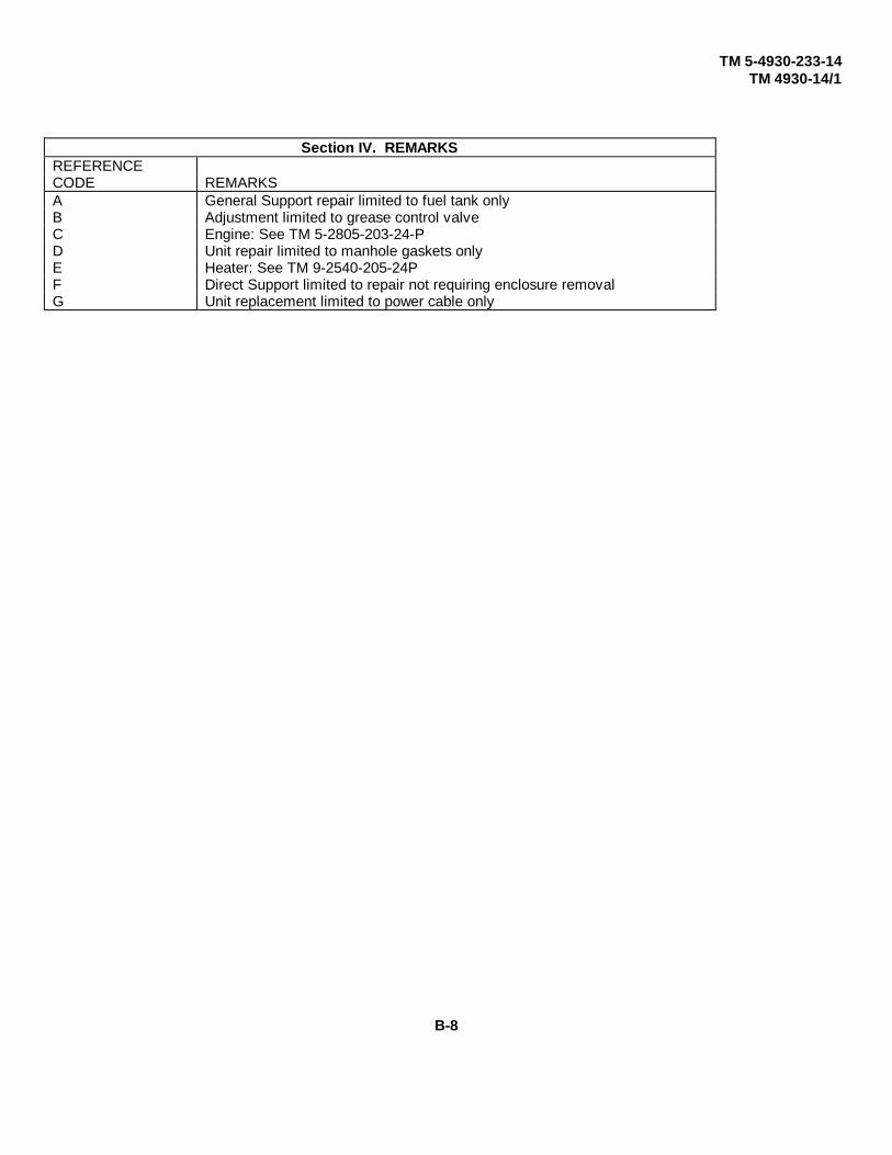
TM 5-4930-233-14TM 4930-14/1
Section IV. REMARKSREFERENCECODE REMARKSA General Support repair limited to fuel tank onlyB Adjustment limited to grease control valveC Engine: See TM 5-2805-203-24-PD Unit repair limited to manhole gaskets onlyE Heater: See TM 9-2540-205-24PF Direct Support limited to repair not requiring enclosure removalG Unit replacement limited to power cable only
B-8

TM 10-4930-233-14TM 4930-14/1
Appendix C
COMPONENTS OF END ITEM AND BASIC ISSUE ITEMS LISTS
Section I. INTRODUCTION
C-1. SCOPE
This appendix lists components of end item and basic issue items for the Lubrication and Servicing Unit to help youinventory items required for safe and efficient operation.
C-2. GENERAL
The Components of End Item and Basic Issue Items Lists are divided into the following sections:
a. Section II Components of End Item. This listing is for informational purposes only, and is not authority torequisition replacements. These items are part of the end item, but are removed and separately packaged fortransportation or shipment. As part of the end item, these items must be with the end item whenever it is issued ortransferred between property accounts. Illustrations are furnished to assist you in identifying the items.
b. Section III. Basic Issue items. These are the minimum essential items required to place the Lubrication andServicing Unit in operation, to operate it and to perform emergency repairs. Although shipped separately packaged, Bllmust be with the Lubrication and Servicing Unit during operation and whenever it is transferred between propertyaccounts. The illustrations will assist you with hard-to-identify items. This manual is your authority to request/requisitionreplacement Bll, based on TOE/MTOE authorization of the end item.
C-3. EXPLANATION OF COLUMNS
The following provides an explanation of columns found in the tabular listings:a. Column (1) - Illustration Number (Illus Number). This column indicates the number of the illustration in which
the item is shown.b. Column (2) - National Stock Number. Indicates the National stock number assigned to the item and will be
used for requisitioning purposes.c. Column (3) - Description. Indicates the Federal item name and, if required, a minimum description to
identify and locate the item. The last line for each item indicates the FSCM (in parentheses) followed by the partnumber.
d. Column (6) - Unit of Measure (U/M). Indicates the measure used in performing the actualoperational/maintenance function. This measure is expressed by a two-character alphabetical abbreviation (e.g., ea, in,pr).
e. Column (7) - Quantity required (Qty rqr). Indicates the quantity of the item authorized to be used with/on theequipment.
C-1

TM 10-4930-233-14TM 4930-14/1
Section II. COMPONENTS OF END ITEM
1 2 3 4 5 6 7Illus National Stock QtyNum- Number Description FSCM Part Number U/M rqrber1 4940-01-040-7193 Air Blow Gun 57733 8338-ISP EA 12 4910-01-138-9105 Tire Inflator Assembly 81348 GG-G-91, Type- EA 1
III, Style 33 4930-00-288-1511 Adapter, Flexible 97403 13227E9554-3 EA 24 4930-00-868-6709 Sleeve, Slip 57733 310048 EA 25 4720-00-917-8332 Hose, Lubricating 81348 MIL-L4387 EA 26 4930-00-377-6820 Fitting, Lubrication 57733 6304B EA 27 4930-01-388-6192 Adapter, Flexible 97403 13227E9554-4 EA 18 4930-00-868-6769 Sleeve, Slip 57733 B10048 EA 19 4720-00-148-5084 Hose, Lubricating 81348 MIL-L-4387 EA 110 4930-00-422-9435 Fitting, Lubrication 57733 304300-A EA 111 4930-00-212-5825 Adapter, Flexible 97403 13227E9554-5 EA 112 4930-00-868-6769 Sleeve, Slip 57733 310048 EA 113 4720-00-148-5084 Hose, Lubricating 81348 MIL-L-4387 EA 114 4730-01-391-7242 Fitting, Lubrication 57733 42030-A EA 115 4930-01-B79-9560 Adapter, Rigid, Swivel 97403 13227E9554-8 EA 116 4930-00-141-8258 Adapter, Rigid 57733 6278 EA 117 4730-01-164-8930 Tee, Street 57733 50500 EA 118 4930-00-377-6820 Valve 57733 6304B EA 119 4930-00-141-8258 Adapter, Rigid 57733 6278 EA 120 5340-01-015-9017 Clip, Retaining 81348 MIL-C-24066/ EA 9
2-32521 5320-01-049-9232 Rivet, Pop 81348 SAE J1200 EA 1822 4930-00-224-8487 Rivet, Pop 81348 SAE J1200 EA 823 5110-00-223-4972 Frame, Hacksaw 81348 GGG-F-671 EA 124 5110-00-277-4587 Blade, Hacksaw, Type I, GR A 81348 GGG-B-451 EA 225 4720-00-222-0966 Fitting, Giant Buttonhead 97403 13227E9646-1 EA 326 4730-00-223-6411 Fitting, Lubrication 97403 13227E9646-2 EA 327 4730-01-382-3099 Fitting, Lubrication 97403 13227E9646-3 EA 328 4730-00-223-6416 Fitting, Lubrication 97403 13227E9647-1 EA 329 4730-00-222-1008 Fitting, Lubrication 97403 13227E9647-2 EA 330 4730-00-223-6414 Fitting, Lubrication 97403 13227E9647-3 EA 331 4730-00-050-4208 Fitting, Lubrication 96906 MS15003-1 EA 632 4730-00-172-0028 Fitting, Lubrication 95879 MS15003-4 EA 633 4730-00-050-4203 Fitting, Lubrication 96906 MS15001-1 EA 634 4730-00-050-4205 Fitting, Lubrication 95879 MS15001-3 EA 135 5120-00-910-8370 Tool, Lubrication 97403 13227E9648-1 EA 136 5120-01-396-9446 Tool, Lubrication 97403 13227E9648-2 EA 137 4730-00-278-3462 Plug 96906 MS27769-2 EA 338 4730-01-B79-6793 Coupling 57733 328030 EA 139 4730-01-B80-2095 Coupling, Half 57733 328034 EA 340 4730-00-986-0175 Coupling, Reusable 97403 13227E9649 EA 641 Coupling, Reusable 97403 13227E9650 EA 6
C-2 Change 1

TM 10-4930-233-14TM 4930-14/1
Section II. COMPONENTS OF END ITEM
1 2 3 4 5 6 7Illus National Stock QtyNum- Number Description FSCM Part Number U/M rqrber42 4730-01-382-2862 Coupling, Reusable 97403 13227E9651 EA 343 4730-01-386-3399 Coupling, Reusable 97403 13227E9652 EA 344 4930-00-266-9182 Gun, Fluid Suction 81348 GGG-0-591 EA 145 4930-00-253-2478 Gun, Grease Hand 57733 500 EA 146 5340-00-299-0340 Loop, Footman 96906 MS51939(WC)-3 EA 447 5340-01-396-7999 Strap Assembly 97403 13227E9443-2 EA 148 4930-00-222-2975 Gun, Oil Spray 57733 5328C EA 149 4930-00-554-6778 Oiler, Hand Pump 57733 5336 EA 150 4930-00-893-3890 Lubricator, Portable 97403 13227E9653 EA 151 4930-00-910-8374 Handle, Control 03990 71880 EA 152 4720-00-758-0494 Hose 03990 621509-04 EA 153 4310-01-242-8044 Tank 640105 EA 154 5120-00-342-4662 Wrench, Bung 97403 13227E9654 EA 155 4720-01-394-6472 Hose, Assembly, Air 97403 13227E9574 EA 156 8110-01-395-4866 Cover, Drum 97403 13227E9477 EA 157 4730-01-B79-798 Swivel, Straight 81348 MIL-C-4387 EA 158 4730-01-386-4308 Swivel, Z 57733 331107 EA 159 Transfer Pump 57733 7216-4 EA 1
Change 1 C-3
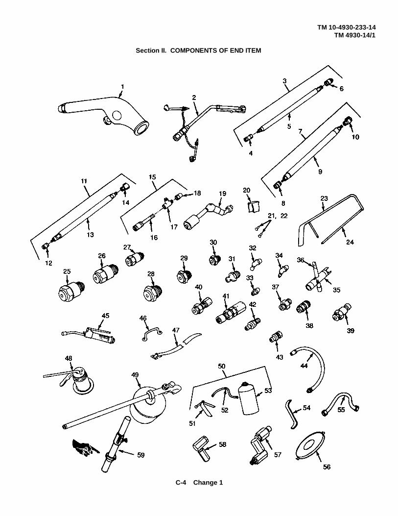
TM 10-4930-233-14TM 4930-14/1
Section II. COMPONENTS OF END ITEM
C-4 Change 1

TM 10-4930-233-14TM 4930-14/1
Section III. BASIC ISSUE ITEMS
(1) (2) (3) (4) (5)Illus National Stock Description, CAGEC, Usable Qty
Number Number and Part Number on Code U/M rqr1 Technical Manual 1 12 5120-00-224-7330 Jack 1 13 5120-00-034-2120 Lug Wrench 1 1
*U.S. GOVERNMENT PRINTING OFFICE: 1995-655-121 / 2 0 227
Change 1 C-5/( C-6 blank)

TM 5-4930-233-14TM 4930-14/1
Appendix D
ADDITIONAL AUTHORIZATION LISTNOT APPLICABLE
D-1/( D-2 blank)
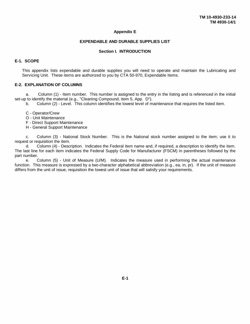
TM 10-4930-233-14TM 4930-14/1
Appendix E
EXPENDABLE AND DURABLE SUPPLIES LIST
Section I. INTRODUCTION
E-1. SCOPE
This appendix lists expendable and durable supplies you will need to operate and maintain the Lubricating andServicing Unit. These items are authorized to you by CTA 50-970, Expendable Items.
E-2. EXPLANATION OF COLUMNS
a. Column (1) - Item number. This number is assigned to the entry in the listing and is referenced in the initialset-up to identify the material (e.g., "Cleaning Compound, item 5, App. D").
b. Column (2) - Level. This column identifies the lowest level of maintenance that requires the listed item.
C - Operator/CrewO - Unit MaintenanceF - Direct Support MaintenanceH - General Support Maintenance
c. Column (3) - National Stock Number. This is the National stock number assigned to the item; use it torequest or requisition the item.
d. Column (4) - Description. Indicates the Federal item name and, if required, a description to identify the item.The last line for each item indicates the Federal Supply Code for Manufacturer (FSCM) in parentheses followed by thepart number.
e. Column (5) - Unit of Measure (U/M). Indicates the measure used in performing the actual maintenancefunction. This measure is expressed by a two-character alphabetical abbreviation (e.g., ea, in, pr). If the unit of measurediffers from the unit of issue, requisition the lowest unit of issue that will satisfy your requirements.
E-1

TM 10-4930-233-14TM 4930-14/1
1 2 3 4 5Item National Stock
Number Level Number Description U/M
1 C Alcohol sh
2 F Aluminum Alloy, SheetQQ-A-250/11 T4
3 O 9150-01-102-3650 Brake Fluid, Silicone (BFS) eaMIL-B-46167 1-Qt Can
4 O Caulking CompoundMIL-C-15705A
5 O 7930-00-282-9699 Detergent, GP, LIQ, WS, A glMIL-D-16791 (81349)1-Gallon Can
6 O 6850-00-669-5685 Dry Cleaning Solvent, A-A-711, drType I and Type II
7 O 3439-01-045-7940 Flux, Solder, Liquid, Rosin Base qtMIL-F-14256
8 O 9150-00-935-1017 Grease, Automotive Art, GAA ty14-Oz Can MIL-G-19204 (81349)
9 F 8030-00-181-8372 Primer, Sealing Compound oz6-Oz CanMIL-S-22473 Grade T (05972)
10 F 8140-00-339-0310 Sealing Compound ea50-cc BottleMIL-S-22473 (05972)
11 O 9150-00-265-9425 Oil Lubricating, OE/HDO eaMIL-L-2104 (81349) 1-Quart Can
12 O 9150-00-402-4478 Oil, Lubricating ICE, Arctic, OEA eaMIL-L-46167, 1-Quart Can
13 O 8010-00-935-7080 Primer Coatings, Epoxy-PolyamideMIL-P-23377
14 Sealant, Silicon
E-2
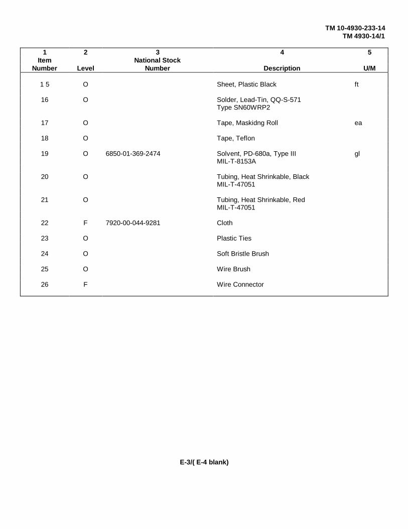
TM 10-4930-233-14TM 4930-14/1
1 2 3 4 5Item National Stock
Number Level Number Description U/M
1 5 O Sheet, Plastic Black ft
16 O Solder, Lead-Tin, QQ-S-571Type SN60WRP2
17 O Tape, Maskidng Roll ea
18 O Tape, Teflon
19 O 6850-01-369-2474 Solvent, PD-680a, Type III glMIL-T-8153A
20 O Tubing, Heat Shrinkable, BlackMIL-T-47051
21 O Tubing, Heat Shrinkable, RedMIL-T-47051
22 F 7920-00-044-9281 Cloth
23 O Plastic Ties
24 O Soft Bristle Brush
25 O Wire Brush
26 F Wire Connector
E-3/( E-4 blank)

TM 5-4930-233-14TM 4930-14/1
Appendix F
ILLUSTRATED LIST OF MANUFACTURED ITEMS
OVERVIEW
This appendix includes complete instructions for making items to be manufactured or fabricated at organizationalmaintenance.
A part number index in alphanumeric order is provided for cross-referencing the part number of the item to bemanufactured to the figure which covers fabrication criteria.
All bulk materials needed for manufacture of an item are listed by part number or specification number in a tabularlist on the illustration.
INDEX PART NAME FIGURE
Chocks, Wheel Figure F-1
Plate Anchor, Shipping Figure F-2
F-1

TM 5-4930-233-14TM 4930-14/1
Figure F-2 Plate Anchor, Shipping
F-2
Figure F-1. Chocks, wheel
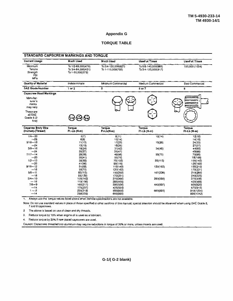
TM 5-4930-233-14TM 4930-14/1
Appendix G
TORQUE TABLE
G-1/( G-2 blank)

TM 5-4930-233-14TM 4930-14/1
A Disassembly, 4-102Installation, 4-104
Adapters Removal, 4-101Extension Hydraulic Pressure Relief, 2-23 Repair, 4-102Flexible Extension, 2-23 Alcohol Injector, Service, 3-11Straight and Z-Swivel, 2-24
AlternatorAir Brake Assembly, 4-140 Assembly, 5-64
Disassembly, 5-58Air Chuck, Use of, 2-21 Disassembly, 5-58
Installation, 4-67Air Cleaner Assembly Removal, 4-67
Assembly, 4-148 Repair, 5-61Disassembly, 4-147 Test, 4-66Installation, 4- 149 Auxiliary Equipment, Operation of, 2-22Removal, 4-146Repair, 4-148 Axle Assembly, Wheel and Tire Service, 3-12
Air Compressor AssemblyAssembly, 5-72 BDisassembly, 5-66Installation, 4-83 Battery Box AssemblyRemoval, 4-81 Assembly, 4-44Repair, 5-72 Disassembly, 4-42Test, 5-52 Installation, 4-45
Air Compressor Hose, Lines and Fittings Removal, 4-40Installation, 4-96 Repair, 4-43Removal, 4-94 Service, 4-37
Air Filter BeltsCleaning, 3-10 Adjustment, 4-62Installation, 3-10 Installation, 4-60Removal, 3-10 Removal, 4-57
Air Receiver Tank Brake AssemblyInstallation, 4-93 Adjustment, 4-170Removal, 4-92 Assembly, 4-176
Bleeding, 4-171Air Regulator Disassembly, 4-174
Assembly, 5-88 Inspection, 4-169Disassembly, 5-87 Removal, 4-172Installation, 4-106 Repair, 4-175Removal, 4-105Repair, 5-87 Brake Lines and Hoses
Installation, 4-152Air Supply Valve Removal, 4-150
Installation, 4-145Removal, 4-144
Air, Lube and Grease Hoses CAssembly, 5-51Disassembly, 5-51 Characteristics, Features and Capabilities, 1-2Installation, 4-50 Clearance LightRemoval, 4-50 Installation, 4-159Repair, 5-51 Removal, 4-159
Alcohol Injector Test, 4-158Adjustment, 4-100 Components of End Item and Basic Issue Items,Assembly, 4-103 C-1
INDEX-1
TM 5-4930-233-14TM 4930-14/1
Control Box Repair, 5-33Assembly, 5-121 Doors (Direct Support)Disassembly, 5-120 Disassembly, 5-11Installation, 4-121 Installation, 5-12Removal, 4-121 Repair, 5-12Repair, 5-120 Doors (Unit)Test, 4-120 Installation, 4-19
Control Panel Removal, 4-18Assembly, 4-75 Ducts, Heater Hoses and Exhaust SystemDisassembly, 4-74 Installation, 4-126Installation, 4-76 Removal, 4-126Removal, 4-72Repair, 4-74Test, 4-70 E
Control Valve - Grease Emergency Relay ValveAdjustment, 5-49 Installation, 4-143Assembly, 5-47 Removal, 4-142Disassembly, 5-45 Enclosure (Unit)Repair, 5-47 Installation, 4-17
Controls, Operator's, 2-1 Removal, 4-16Enclosure and Skid Assembly
Coupler (Glad Hand) Installation, 5-9Assembly, 4-141 Removal, 5-9Disassembly, 4-140 EngineInstallation, 4-141 Installation, 4-88Removal, 4-140 Removal, 4-84Repair, 4-141
Engine Exhaust SystemInstallation, 4-99Removal, 4-98
D Engine Oil DispensersDirect Support Troubleshooting Assembly, 5-42
Disassembly, 5-37Air Compressor, 5-6 Installation, 4-48Axle Assembly, 5-7 Removal, 4-48Brake Assembly, 5-8 Repair, 5-41Engine Oil Dispenser, 5-3Gear Lube Dispensers, 5 -2 Engine Oil Extension AssemblyGrease Control Valve, 5-4 Installation, 4-97High Pressure Pump, 5-5 Removal, 4-97Low Pressure Pump, 5-5 Engine Oil, Dispensing, 2-20Transfer Pump, 5-2 Equipment Data, 1-4
Dispensers - Engine Oil Equipment Descriptions, 1-2Assembly, 5-42 Exhaust System, EngineDisassembly, 5-37 Installation, 4-99Installation, 4-48 Removal, 4-98Removal, 4-48 Expendable/Durable Supplies and Materials List,Repair, 5-41 E-1
Dispensers - Gear LubeAssembly, 5-34 FDisassembly, 5-29Installation, 4-48 FittingsRemoval, 4-48 45x Hydraulic Lubrication, 2-24
INDEX-2
TM 5-4930-233-14TM 4930-14/1
Air Hose End, 2-24 Grease Control ValveButtonhead, 2-24 Adjustment, 5-49High Pressure Hose End, 2-24 Assembly, 5-47Straight Hydraulic, 2-24 Disassembly, 5-45
Fording, 2-38 Repair, 5-47Grease Hoses - Air, Lube
Frame and Skid AssemblyRepair, 5-122, 6-4 Assembly, 5-51Replace, 6-3 Disassembly, 5-51
Installation, 4-50Frame Assembly Removal, 4-50
Repair, 6-5 Repair, 5-51Replacement, 5-132 Gun
Fuel Cap and Neck Assembly Air Blow, 2-23Assembly, 4-24 Hand Lever Grease, 2-22Disassembly, 4-23 Oil Spray, 2-25Installation, 4-25 Suction, 2-22Removal, 4-22Repair, 4-23
Fuel Pump HInstallation, 4-123 Head (Air Compressor)Removal, 4-123 Assembly, 5-82Test, 4-122 Disassembly, 5-80
Fuel Tank Installation, 5-84Assembly, 5-27 Removal, 5-78Cleaning, 4-31 Repair, 5-82Disassembly, 5-25 Heater - Winterization AssemblyDraining, 4-30 Installation, 4-118Installation, 4-32 Removal, 4-115Removal, 4-32Repair, 5-27, 6-1 Heater Hoses and Exhaust System - Ducts
Installation, 4-126Removal, 4-126
G High Pressure PumpsAssembly, 5-110
Gear Lube Dispensers Disassembly, 5-102Assembly, 5-34 Installation, 4-108Disassembly, 5-29 Removal, 4-107Installation, 4-48 Repair, 5-110Removal, 4-48 Hose, Lines and Fittings - Air CompressorRepair, 5-33 Installation, 4-96
Gear Oil, Dispensing, 2-20 Removal, 4-94Hoses - Air, Lube and Grease
General Maintenance, 4-14 Assembly, 5-51General Purpose Grease, Dispensing, 2-18 Disassembly, 5-51General Wiring Repair, 4-15 Repair, 5-51Glad Hand - Coupler
Assembly, 4-141 JDisassembly, 4-140Installation, 4-141 Jack Leg AssemblyRemoval, 4-140 Installation, 4-180Repair, 4-141 Removal, 4-179
INDEX-3

TM 5-4930-233-14TM 4930-14/1
Junction Box - Trailer Maintenance, Unit, 4-1Installation, 4-156 Manufactured Items, Illustrated List of, F-Removal, 4-156Test, 4-154
OL Oil Extension Assembly, Engine
Installation, 4-97Light - Clearance Removal, 4-97
Installation, 4-159 Operating Instructions, 2-1Removal, 4-159 Operator's Controls, 2-1Test, 4-158
Operating Procedure, 2-12Light - Stop and Turn Dispensing Engine Oil, 2-20
Installation, 4-161 Dispensing Gear Oil, 2-19Removal, 4-161 Dispensing General Purpose Grease, 2-18Test, 4-160 Engine Starting, 2-12
Lines and Hoses - Brakes Engine Stopping, 2-13Installation, 4-152 Filling Lube Tank, 2-14Removal, 4-150 Preparing Lube Pumps for Operation, 2-16
Shutdown Procedures, 2-21Low Pressure Pumps Use of Air Chuck, 2-21
Assembly, 5-96Disassembly, 5-89 Operating Under Unusual Conditions, 2-34Installation, 4-108 Operation and Safety Instructions, 2-32Removal, 4-107Repair, 45-95 Operation in Dusty or Sandy Areas, 2-37Repair, 5-95
Operation in Extreme Cold, 2-34Lube Piping Alcohol Injector, 2-36
Installation, 4-130 At-Halt Parking, 2-37Removal, 4-128 Batteries, 2-34Repair, 4-130 Care of Lubricants, 2-34
Lube Pumps, Preparing for Operation, 2-16 Cold Engine Starting, 2-35Lube Tank Compressed Air System, 2-34
Assembly, 4- 113 Electrical System, 2-34Disassembly, 4 - 111 Exhaust Heat Diverter, 2-35Installation, 4-114 Fuel System, 2-34Removal, 4-109 Lubrication, 2-34Repair, 4-112, 5-119 Towing in Extreme Cold, 2-37
Valves, 2-35Lube Tank Assembly, Service, 3-11 Winterization Assembly, 2-36
Lube Tank, Filling, 2-14 Operation in Extreme Heat, 2-37
Lubrication Instructions, 3-1 Operation in High Altitudes, 2-38Skid Sub Assembly, 3-1 Operation in Salt Water Areas, 2-38Trailer Assembly, 3-2
Operation of Auxiliary Equipment, 2-2245x Hydraulic Lubrication Fittings, 2-24
M Air Blow Gun, 2-23Air Hose End Fittings, 2-24Buttonhead Fittings, 2-24
Maintenance Allocation Chart, B- 1 Easy Out Tools, 2-24Maintenance Instructions Extension Hydraulic Pressure Relief Adapter,
Direct Support, 5-1 2-23Operator's, 3-1 Flexible Extension Adapter, 2-23Unit, 4-1 Hacksaw Frame and Blade, 2-22
INDEX-4
TM 5-4930-233-14TM 4930-14/1
Hand Lever Grease Gun, 2-22 Removal, 4-132Hand Oiler, 2-25 Repair, 4-134High Pressure Hose End Fittings, 2-24 Power ClusterOil Spray Gun, 2-25 Assembly, 5-126Plug, 2-24 Disassembly, 5-126Quick-Disconnect Air Line Couplings, 2-24 Installation, 5-128Straight and Z-Swivel Adapters, 2-24 Removal, 5-124Straight Hydraulic Fittings, 2-24 Repair, 5-126Suction Gun, 2-22Tire Inflator, Pressure Gage and Chucks, 2-23 Preliminary Servicing and Adjustment of Equip-
ment, 4-2Operation Under Rainy or Humid Conditions,
2-37 Preparation for Movement, 2-26After Towing, 2-29
Operator Troubleshooting, 3-3 Driving, 2-29Air Brakes, 3-8 Preparation for Towing, 2-26Axle Assembly, 3-9Compressor, 3-5 Preparation for Storage or Shipment, 4-181Engine, 3-4 Preservation, 4-181Reel Assembly, 3-6Trailer Electrical, 3-8 Pressure Relief ValveTransfer Pump, 3-7 Installation, 4-80
Removal, 4-80Operator's Maintenance Instructions, 3-1
ProceduresOperator's Preventative Maintenance Checks and Operation, 2-12
Services, 2-7 Shutdown, 2-21Operator PMCS Table, 2-9
Pumps - Low PressureInstallation, 4-108
P Removal, 4-107Pumps - High Pressure
Packing Assembly, 5-110Overview, 4-183 Disassembly, 5-102Shipment, 4-184 Installation, 4-108Storage, 4-184 Repair, 5-110
Panels Pumps - Low PressureInstallation, 4-21 Assembly, 5-96Removal, 4-20 Disassembly, 5-89Repair, 5-13 Repair, 5-95
Pilot ValveAdjustment, 4-78 RInstallation, 4-79Removal, 4-79 Reel Assembly
Piping - Lube Assembly, 4-55Installation, 4-130 Disassembly, 4-53Removal, 4-128 Installation, 4-56Repair, 4-130 Removal, 4-52
Piping - Pneumatic Repair, 4-54Installation, 4-135 Reel Cabinet. AssemblyRemoval, 4-132 Disassembly, 4-33Repair, 4-134 Installation, 4-35
Pneumatic Piping Repair, 4-34Installation, 4-135 References, A- 1
INDEX-5

TM 5-4930-233-14TM 4930-14/1
Regulator - Air Tank, Air ReceiverAssembly, 5-88 Installation, 4-93Disassembly, 5-87 Removal, 4-92Installation, 4-106 TestingRemoval, 4-105 Alternator, 4-66Repair, 5-87 Starter, 4-64
Wiring Harness (Air Compressor), 4-68Control Box, 4-120
S Control Panel, 4-70Fuel Pump, 4-122
Service Upon Receipt, 4-1 Wiring Harness (Trailer), 4-162Shipment and Storage, 4-183 Air Compressor, 5-5 2
Starter, 5-57Skid Assembly, Enclosure Wiring Harness (Winterization Assy.), 4-124
Installation, 5-9 Clearance Light, 4-158Removal, 5-9 Junction Box, 4-154
Skid Sub Assembly, 4-27 Stop and Turn Light, 4-160Starter Tire Assembly, Wheel and
Assembly, 5-56 Installation, 4-168Disassembly, 5-53 Removal, 4-16Installation, 4-65 Repair, 4-167Removal, 4-65 Tool Box AssemblyRepair, 5-55 Assembly, 4-29Test, 4-64, 5-57 Disassembly, 4-28
Installation, 4-29Starting Engine, 2-12 Removal, 4-27
Removal, 4-27Stop and Turn Light Repair, 4-28
Installation, 4-161 Tools, Easy Out, 2-24Removal, 4-161Test, 4-160 Torque Table, G-1
Stopping Engine, 2-13 Trailer Assembly, 4-179Storage - Inspection in Administrative Trailer Assembly - Components
Inspection, 4-185 Installation, 4-138Overview, 4-185 Removal, 4-136
Transfer PumpAdjustment, 5-22
T Assembly, 5-19Disassembly, 5-15
Tank - Fuel Installation, 5-24Assembly, 5-27 Removal, 5-14Cleaning, 4-31 Repair, 5-19Disassembly, 5-25 Troubleshooting - Operator, 3-3Draining, 4-30 Air Brakes, 3-8Installation, 4-32 Axle Assembly, 3-9Removal, 4-32 Compressor, 3-5Repair, 5-27 Engine, 3-4
Tank - Lube Reel Assembly, 3-6Assembly, 4-113 Trailer Electrical, 3-8Disassembly, 4-111 Transfer Pump, 3-7Inspection, 4-114 Troubleshooting - UnitRemoval, 4-109 Batteries, 4-8Repair, 4-112 Compressor, 4-10
INDEX-6
TM 5-4930-233-14TM 4930-14/1
Control Panel Gages, 4-13 Disassembly, 5-45Engine, 4-8 Repair, 5-47Lights, 4-12 Valve-PilotLubricant Dispenser, 4-11 Adjustment, 4-78Wheel Brakes, 4-11 Installation, 4-7Winterization Assembly, 4-10 Removal, 4-79
Valve - Pressure Relief, 4-80U Installation, 4-80
Removal, 4-80Unit Maintenance Instructions, 4-1 Valve, Air Supply
Common Tools and Equipment, 4-1 Installation, 4-145Repair Parts, 4-1 Removal, 4-144Special Tools, TMDE, and Support Equipment,
4-1Unit Preventative Maintenance Checks and Ser- W
vices, 2-7Unit PMCS Table, 2-9 Wheel and Tire Assembly
Installation, 4-168Unit Troubleshooting Removal, 4-165
Batteries, 4-8 Repair, 4-167Compressor, 4-10Control Panel Gages, 4-13 Wheel and Tire, Service, 3-12Engine, 4-8 Wheel Assembly, Wheel and Tire Service, 3-12Lights, 4-12Lubricant Dispenser, 4 - 11 Winterization Assembly, 4-115Wheel Brakes, 4-11 Wiring Harness - Air BrakeWinterization Assembly, 4-10 Installation, 4-164
Unloader - Centrifugal Removal, 4-163Installation, 5-86 Repair, 4-164Removal, 5-85 Test, 4-162
Wiring Harness - Air CompressorInstallation, 4-69
V Removal, 4-69Repair, 4-69
Valve - Emergency Relay Test, 4-68Installation, 4-143 Wiring Harness - Winterization AssemblyRemoval, 4-142 Installation, 4-125
Valve - Grease Control Removal, 4-125Adjustment, 5-49 Repair, 4-125Assembly, 5-47 Test, 4-124
INDEX-7/(INDEX-8 blank)

TM 5-4930-233-14TM 4930-14/1
By Order of the Secretaries of the Army and Navy (Including the Marine Corps):
GORDON R. SULLIVANGeneral, United States Army
Official: Chief of Staff
MILTON H. HAMILTONAdministrative Assistant to the
Secretary of the Army04339
DAVID E. BOTTORFFRear Admiral, CEC, US NavyCommanderNavy Facilities EngineeringCommand
RONALD D. ELLIOTExecutive DirectorMarine Corps Systems Command
DISTRIBUTION:To be distributed in accordance with DA Form 12-25-E, block no. 0826, requirements for TM 5-4930-233-14.
*U S GOVERNMENT PRINT OFFICE: 1993 755-120/60212
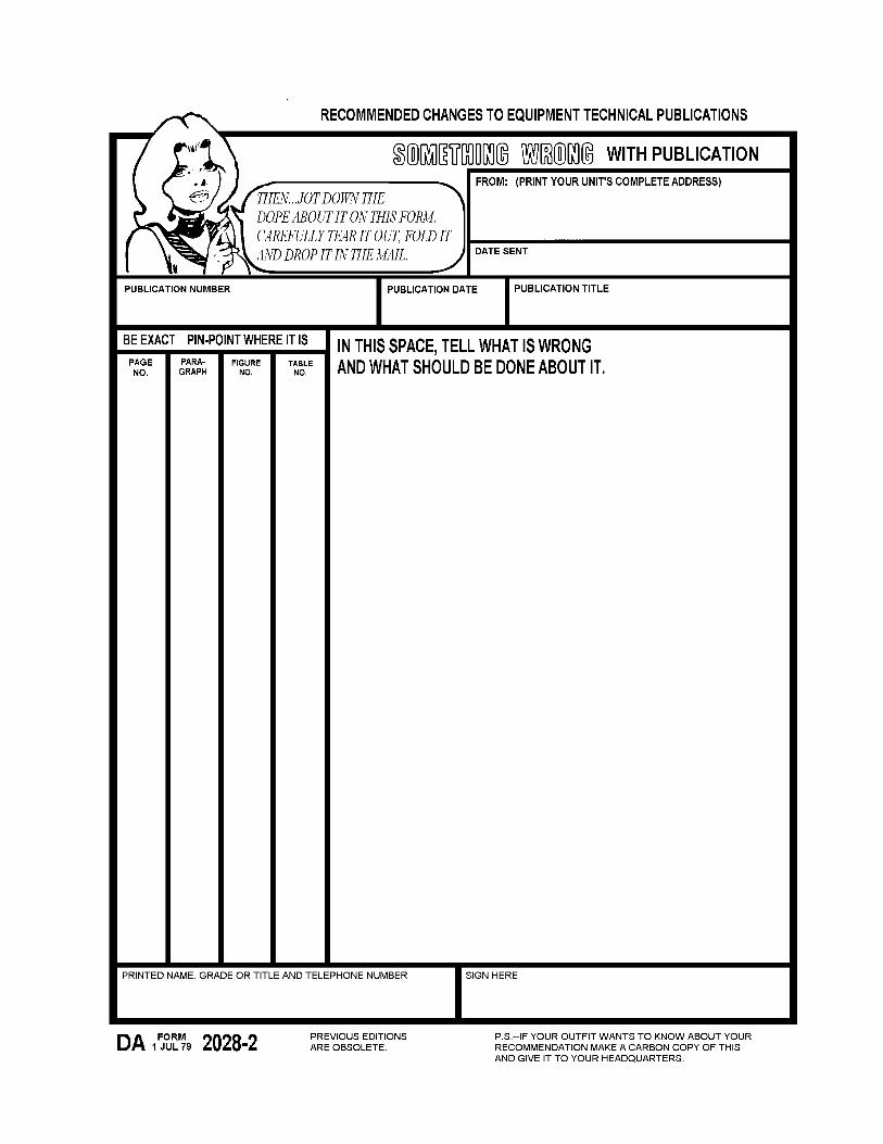
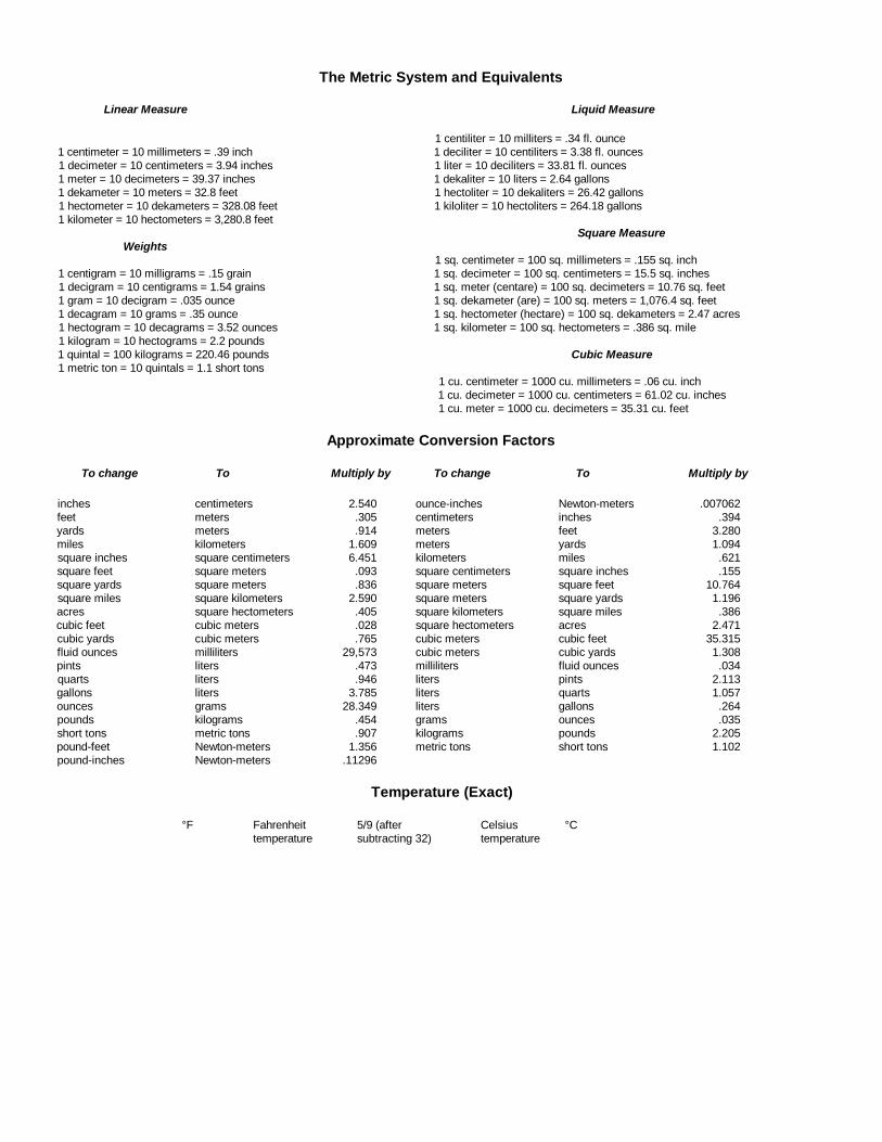
The Metric System and Equivalents
Linear Measure Liquid Measure
1 centiliter = 10 milliters = .34 fl. ounce1 centimeter = 10 millimeters = .39 inch 1 deciliter = 10 centiliters = 3.38 fl. ounces1 decimeter = 10 centimeters = 3.94 inches 1 liter = 10 deciliters = 33.81 fl. ounces1 meter = 10 decimeters = 39.37 inches 1 dekaliter = 10 liters = 2.64 gallons1 dekameter = 10 meters = 32.8 feet 1 hectoliter = 10 dekaliters = 26.42 gallons1 hectometer = 10 dekameters = 328.08 feet 1 kiloliter = 10 hectoliters = 264.18 gallons1 kilometer = 10 hectometers = 3,280.8 feet
Square MeasureWeights
1 sq. centimeter = 100 sq. millimeters = .155 sq. inch1 centigram = 10 milligrams = .15 grain 1 sq. decimeter = 100 sq. centimeters = 15.5 sq. inches1 decigram = 10 centigrams = 1.54 grains 1 sq. meter (centare) = 100 sq. decimeters = 10.76 sq. feet1 gram = 10 decigram = .035 ounce 1 sq. dekameter (are) = 100 sq. meters = 1,076.4 sq. feet1 decagram = 10 grams = .35 ounce 1 sq. hectometer (hectare) = 100 sq. dekameters = 2.47 acres1 hectogram = 10 decagrams = 3.52 ounces 1 sq. kilometer = 100 sq. hectometers = .386 sq. mile1 kilogram = 10 hectograms = 2.2 pounds1 quintal = 100 kilograms = 220.46 pounds Cubic Measure1 metric ton = 10 quintals = 1.1 short tons
1 cu. centimeter = 1000 cu. millimeters = .06 cu. inch1 cu. decimeter = 1000 cu. centimeters = 61.02 cu. inches1 cu. meter = 1000 cu. decimeters = 35.31 cu. feet
Approximate Conversion Factors
To change To Multiply by To change To Multiply by
inches centimeters 2.540 ounce-inches Newton-meters .007062feet meters .305 centimeters inches .394yards meters .914 meters feet 3.280miles kilometers 1.609 meters yards 1.094square inches square centimeters 6.451 kilometers miles .621square feet square meters .093 square centimeters square inches .155square yards square meters .836 square meters square feet 10.764square miles square kilometers 2.590 square meters square yards 1.196acres square hectometers .405 square kilometers square miles .386cubic feet cubic meters .028 square hectometers acres 2.471cubic yards cubic meters .765 cubic meters cubic feet 35.315fluid ounces milliliters 29,573 cubic meters cubic yards 1.308pints liters .473 milliliters fluid ounces .034quarts liters .946 liters pints 2.113gallons liters 3.785 liters quarts 1.057ounces grams 28.349 liters gallons .264pounds kilograms .454 grams ounces .035short tons metric tons .907 kilograms pounds 2.205pound-feet Newton-meters 1.356 metric tons short tons 1.102pound-inches Newton-meters .11296
Temperature (Exact)
°F Fahrenheit 5/9 (after Celsius °Ctemperature subtracting 32) temperature

PIN: 066807-000

This fine document...
Was brought to you by me:
Liberated Manuals -- free army and government manuals
Why do I do it? I am tired of sleazy CD-ROM sellers, who take publicly available information, slap “watermarks” and other junk on it, and sell it. Those masters of search engine manipulation make sure that their sites that sell free information, come up first in search engines. They did not create it... They did not even scan it... Why should they get your money? Why are not letting you give those free manuals to your friends?
I am setting this document FREE. This document was made by the US Government and is NOT protected by Copyright. Feel free to share, republish, sell and so on.
I am not asking you for donations, fees or handouts. If you can, please provide a link to liberatedmanuals.com, so that free manuals come up first in search engines:
<A HREF=http://www.liberatedmanuals.com/>Free Military and Government Manuals</A>
– SincerelyIgor Chudovhttp://igor.chudov.com/
– Chicago Machinery Movers