Embed Size (px)
Citation preview

AquiStar® PT12Pressure/Temperature Sensor
INSTRUCTION MANUAL
For PSIG
sensors, refer
to page 7
regarding
desiccant
use!

1
Table of ContentsIntroduction ......................................................................................................................2
PT12 Pressure/Temperature Transducer ....................................................................2Initial Inspection and Handling .................................................................................2Do’s and Don’ts .........................................................................................................2
How Pressure Sensors Work .............................................................................................3Installation & Operation ...................................................................................................5
Using with an SDI-12 Datalogger .............................................................................5Well Installation .........................................................................................................5Other Installations ......................................................................................................6
Maintenance ......................................................................................................................7Trouble Shooting ...............................................................................................................8
Erratic Readings .........................................................................................................8Oscillating Readings Over Time ................................................................................8Zero Readings When Pressurized ..............................................................................9Grounding Issues .......................................................................................................9
Appendix A: Technical Specifi cations ............................................................................10Transducer Components ..........................................................................................10Wiring Information ..................................................................................................10Electrical Specifi cations ...........................................................................................11Mechanical Specifi cations ......................................................................................11Power Supply ...........................................................................................................11Miscellaneous ..........................................................................................................11
Appendix B: SDI-12 Commands and Register Defi nitions ...........................................12SDI-12 Command Nomenclature ............................................................................12SDI-12 Commands ..................................................................................................12Calibration Register Defi nitions ..............................................................................17
Appendix C: Taking Modbus® Readings ......................................................................18Register Defi nitions .................................................................................................18Readings and the Auto-Enable Setting ....................................................................20
Reordering Information .................................................................................................20Limited Warranty/Disclaimer - PT12 .............................................................................21
Information in this document is subject to change without notice and does not represent a commitment on the part of the manufacturer. No part of this manual may be reproduced or transmitted in any form or by any means, electronic or mechanical, including photocopying and recording, for any purpose without the express written permission of the manufacturer.
©1997 - 2013 Instrumentation Northwest, Inc.Registered trademarks and trademarks belong to their respective owners.
2Introduction
PT12 Pressure/Temperature TransducerThe PT12 Pressure Transducer represents the latest state-of-the-art technology and has been designed to provide trouble-free submersible operation in liquid environments, when properly installed and operated. This sensor communicates via SDI-12 (v1.3) or Modbus® protocol.
INW also carries a special version of the PT12 designed to measure barometric pres-sure in reference to absolute pressure. If you are using an absolute PT12, contact your INW representative for details on how our PT12-BV or PT12-BV/Compensator can facilitate obtaining barometrically compensated pressure/level.
Please take the time to read through this manual if you are not familiar with this prod-uct.
Initial Inspection and HandlingUpon receipt of your transducer, inspect the shipping package for damage. If any damage is apparent, note the signs of damage on the appropriate shipping form. After opening the carton, look for concealed damage such as a cut cable. If concealed dam-age is found, immediately fi le a claim with the carrier.
Check the etched label on the transducer to be sure that the proper range and type were provided. Also check the label attached to the cable at the connector end for the proper cable length.
Do’s and Don’ts
Do handle the device with care.Do store the device in a dry, inside area when not in use.Do install a desiccant tube if you are doing long-term outdoor monitoring.
Don’t install the device so that the connector end is submerged.Don’t support the device with the connector or with the connectors of an extension cable. Use a strain relief device to take the tension off the connectors.Don’t allow the device to free-fall down a well at high velocities as impact damage can occur.Don’t bang or drop the device on hard objects.Don’t disassemble the device. (The warranty is void if transducer is disassembled.)
3How Pressure Sensors WorkThe following paragraphs outline the basics of how pressure is measured using sub-mersible pressure transducers:
Liquids and gasses do not retain a fi xed shape. Both have the ability to fl ow and are often referred to as fl uids. One fundamental law for a fl uid is that the fl uid exerts an equal pressure in all directions at a given level. Further, this pressure increases with an increasing depth of “submergence”. If the density of a fl uid remains constant (noncompressible...a generally good assumption for water at “normal” pressures and temperatures), this pressure increases linearly with the depth of “submergence”.
We are all “submerged” in the atmosphere. As we increase our elevation, the pressure exerted on our bodies decreases as there is less of this fl uid above us. It should be noted that atmospheric pressure at a given level does vary with changes in the weather. One standard atmosphere (pressure at sea level on a “normal” day) is defi ned to be 14.7 PSI (pounds per square inch).
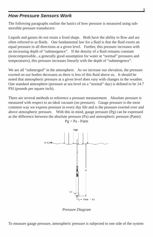
There are several methods to reference a pressure measurement. Absolute pressure is measured with respect to an ideal vacuum (no pressure). Gauge pressure is the most common way we express pressure in every day life and is the pressure exerted over and above atmospheric pressure. With this in mind, gauge pressure (Pg) can be expressed as the difference between the absolute pressure (Pa) and atmospheric pressure (Patm):
Pg = Pa - Patm
Pressure Diagram
To measure gauge pressure, atmospheric pressure is subjected to one side of the system
4and the pressure to be measured is subjected to the other. The result is that the dif-ferential (gauge pressure) is measured. A tire pressure gauge is a common example of this type of device.
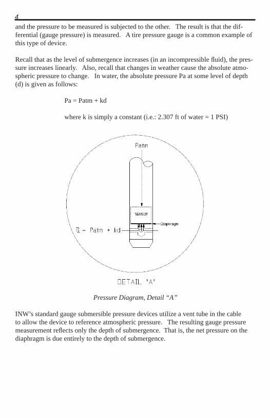
Recall that as the level of submergence increases (in an incompressible fl uid), the pres-sure increases linearly. Also, recall that changes in weather cause the absolute atmo-spheric pressure to change. In water, the absolute pressure Pa at some level of depth (d) is given as follows:
Pa = Patm + kd
where k is simply a constant (i.e.: 2.307 ft of water = 1 PSI)
Pressure Diagram, Detail “A”
INW’s standard gauge submersible pressure devices utilize a vent tube in the cable to allow the device to reference atmospheric pressure. The resulting gauge pressure measurement refl ects only the depth of submergence. That is, the net pressure on the diaphragm is due entirely to the depth of submergence.
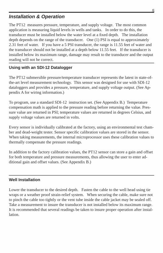
5Installation & OperationThe PT12 measures pressure, temperature, and supply voltage. The most common application is measuring liquid levels in wells and tanks. In order to do this, the transducer must be installed below the water level at a fi xed depth. The installation depth depends on the range of the transducer. One (1) PSI is equal to approximately 2.31 feet of water. If you have a 5 PSI transducer, the range is 11.55 feet of water and the transducer should not be installed at a depth below 11.55 feet. If the transducer is installed below its maximum range, damage may result to the transducer and the output reading will not be correct.
Using with an SDI-12 Datalogger The PT12 submersible pressure/temperature transducer represents the latest in state-of-the-art level measurement technology. This sensor was designed for use with SDI-12 dataloggers and provides a pressure, temperature, and supply voltage output. (See Ap-pendix A for wiring information.)
To program, use a standard SDI-12 instruction set. (See Appendix B.) Temperature compensation math is applied to the pressure reading before returning the value. Pres-sure value are returned in PSI; temperature values are returned in degrees Celsius, and supply voltage values are returned in volts.
Every sensor is individually calibrated at the factory, using an environmental test cham-ber and dead-weight tester. Sensor specifi c calibration values are stored in the sensor. When taking measurements, the internal microprocessor uses these calibration values to thermally compensate the pressure readings.
In addition to the factory calibration values, the PT12 sensor can store a gain and offset for both temperature and pressure measurements, thus allowing the user to enter ad-ditional gain and offset values. (See Appendix B.)
Well Installation
Lower the transducer to the desired depth. Fasten the cable to the well head using tie wraps or a weather proof strain-relief system. When securing the cable, make sure not to pinch the cable too tightly or the vent tube inside the cable jacket may be sealed off. Take a measurement to insure the transducer is not installed below its maximum range. It is recommended that several readings be taken to insure proper operation after instal-lation.

6
Installation
Notes: • If the transducer is to be left in the well for a long-term monitoring applica-
tion and the connector end is not in a dry, thermally-stable environment, a desiccant tube must be installed in line with the cable to prevent condensation in the cable vent tube. Water in the vent tube will cause inaccurate readings and, in time, will work its way into the transducer and damage it.
• Proper grounding is very important! INW recommends the following: (1) the sensor cable shield (the wrapped shield inside the cable) be attached to the power ground on the datalogger and (2) the grounding lug be connected via a 12 AWG or larger wire, to a grounding rod driven into the earth. It is also recommended that if you are using an external power supply to power the datalogger that it be tied to the same earth ground. (See also: Grounding Issues in the Trouble Shooting section of this manual.)
Other Installations
The transducer can be installed in any position; however, when it leaves the factory it is tested in the vertical position. Strapping the transducer body with tie wraps or tape will not hurt it. INW can provide an optional 1/4” NPT input adapter that is interchangeable with the standard end cone for those applications where it is necessary to directly attach the transducer to a pipe, tank or other pipe port. If the transducer is being installed in a fl uid environment other than water, be sure to check the compatibil-ity of the fl uid with the wetted parts of the transducer. INW can provide a variety of seal materials if you are planning to install the transducer in an environment other than water.

7Maintenance
Transducer: There are no user-serviceable parts. If problems develop with sensor stability or accuracy, contact INW. If the transducers have been exposed to haz-ardous materials, do not return them without notifi cation and authorization.
Cable: Cable can be damaged by abrasion, sharp objects, twisting, crimping or crushing and pulling. Take care during installation and use to avoid cable damage. If a section of cable is damaged, it is recommended that you send your sensor back to replace the cable harness assembly.
Connectors (if used): The contact areas (pins & sockets) of the connectors will wear out with extensive use. If your application requires repeated connections, other types of connectors can be provided. The connectors used by INW are not submersible, but are designed to be splash-resistant.
Desiccant Tubes (for gauge or vented units): Inspect the desiccant tube at least once every two months. The desiccant tube prevents moisture in the air from be-ing sucked into the vent tube, which can cause erratic readings and sensor damage.
The desiccant tube is fi lled with blue silica gel beads. A locking barb and a hydro-phobic water fi lter are attached to the end of the desiccant tube. This fi lter pro-longs the life of the desiccant as much as three times over a desiccant tube without the fi lter.
Install the sensor so that the desiccant tube will not fl ood or lie in water.
The desiccant is a bright blue color when active and dry. As moisture is absorbed the color will begin to fade, becoming a light pink, which indicates full satura-tion and time to replace. Replacement desiccant and hydrophobic fi lters can be purchased from INW; please contact an INW sales engineer at 1-800-776-9355 for more information.
Vent tube
Cable
Desiccant tubeHydrophobic fi lter
Desiccant Tube

8Troubleshooting
Erratic Readings
Erratic readings can be caused by a damaged transducer, damaged cable, poor connec-tions or improper operation of readout equipment. In most cases, erratic readings are due to moisture getting into the system. Assuming that the readout equipment is work-ing correctly, the fi rst thing to check is the connection. Look for moisture between contacts or a loose or broken wire. If the connection appears OK, pull the transducer up a known distance while monitoring its output. If the transducer responds approxi-mately as it should, but the reading is still erratic, most likely the cable is damaged. If the transducer does not respond approximately as it should, it is most likely that the sensor is damaged. In either case, consult the factory.
Erratic and erroneous readings can also occur due to improper grounding. See Ground-ing Issues, next page.
Oscillating Readings Over Time
If, after time, your transducer is functioning normally but your data is showing a cyclic effect in the absence of water level changes, you are probably seeing baromet-ric changes. The amount is usually .5 to 1.5 feet of water. This can be caused by a plugged vent tube in the cable or actual water level changes in the aquifer itself in re-sponse to barometric pressure changes. This effect can occur in tight formations where the transducer will immediately pick up barometric changes but the aquifer will not. If you think you are having this type of problem you will have to record the barometric pressure as well as the water level pressure and compensate the data. If it appears that the vent tube is plugged, consult the factory.
If a desiccant tube is not installed in line with the cable, water may have condensed in your vent tube causing it to plug. After you are fi nished installing the desiccant tube you can test the vent tube by applying a small amount of pressure to the end of the desiccant tube and seeing if this affects the transducer reading.
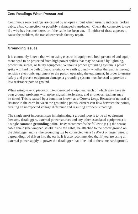
9Zero Readings When Pressurized
Continuous zero readings are caused by an open circuit which usually indicates broken cable, a bad connection, or possibly a damaged transducer. Check the connector to see if a wire has become loose, or if the cable has been cut. If neither of these appears to cause the problem, the transducer needs factory repair.
Grounding Issues
It is commonly known that when using electronic equipment, both personnel and equip-ment need to be protected from high power spikes that may be caused by lightning, power line surges, or faulty equipment. Without a proper grounding system, a power spike will fi nd the path of least resistance to earth ground – whether that path is through sensitive electronic equipment or the person operating the equipment. In order to ensure safety and prevent equipment damage, a grounding system must be used to provide a low resistance path to ground.
When using several pieces of interconnected equipment, each of which may have its own ground, problems with noise, signal interference, and erroneous readings may be noted. This is caused by a condition known as a Ground Loop. Because of natural re-sistance in the earth between the grounding points, current can fl ow between the points, creating an unexpected voltage difference and resulting erroneous readings.
The single most important step in minimizing a ground loop is to tie all equipment (sensors, dataloggers, external power sources and any other associated equipment) to a single common grounding point. INW recommends the following: (1) the sensor cable shield (the wrapped shield inside the cable) be attached to the power ground on the datalogger and (2) the grounding lug be connected via a 12 AWG or larger wire, to a grounding rod driven into the earth. It is also recommended that if you are using an external power supply to power the datalogger that it be tied to the same earth ground.

10Appendix A: Technical Specifi cations
Transducer Components
Components
Wiring Information
Connections
For Modbus® with — with 5-pin connector
For Modbus® — without connector
For SDI-12 — with 5-pin connector
For SDI-12 — without connector
Vent tube
Cable
Desiccant tubeHydrophobic fi lter
WhitePurpleYellowBrownBlueShield (may be green)
12 VDC+ (Vaux)Modbus D- (Not used)Modbus D+ (Not used)SDI-12 Signal12 VDC – (Gnd)Earth ground
WhitePurpleYellowBrownBlueShield
12 VDC+ (Vaux)Modbus D- (Not used)Modbus D+ (Not used)SDI-12 Signal12 VDC – (Gnd)
123455-Pin Connector
WhitePurpleYellowBrownBlueShield (may be green)
12 VDC+ (Vaux)Modbus D- Modbus D+SDI-12 Signal (Not used)12 VDC – (Gnd)Earth ground
WhitePurpleYellowBrownBlueShield
12 VDC+ (Vaux)Modbus D-Modbus D+SDI-12 (Not used)12 VDC – (Gnd)
123455-Pin Connector

11Electrical Specifi cations
Pressure Static Accuracy ±0.1% FSO (maximum) B.F.S.L. 25° C ±0.06% FSO (typical)Maximum Zero Offset ±0.25% FSO at 25° C Resolution 16 bitOver Range Protection 2x (except 300 PSIA and higher)Compensated Temperature Range Standard -20° C to 40° C Extended -40° C to 60° COperating Temperature Range Standard -20° C to 60° C Extended -40° C to 80° C
Mechanical Specifi cations
Transducer:Length 8.3 inches (21.081 cm)Diameter 0.75 inches (1.9 cm)Body Material 316 stainless steel (Titanium available)Wire Seal Material Fluoropolymer and PTFEDesiccant Tube IncludedTerminating Connector Available Option Weight 0.8 lbs. (0.4 kg)
Cable:O.D. 0.28 inch maximum (0.7 cm)Cable Jacket Polyurethane, Polyethylene, or PTFEConductor Type 9-conductor, ventedVent Tube NylonBreak Strength 138 lbs. (62.7 kg)Maximum Length 200 ft. (61 m) for SDI-12 2000 ft. (610 m) for Modbus®
Weight 4 lbs. per 100 feet (1.8 kg per 30 m)
Power Supply
Voltage 9.0 to 16.0 VDCCurrent - Active 3 mA Avg / 10mA PeakCurrent - Sleep 150uA
Miscellaneous
Measurement Latency Approx. 1.3 secondsDefault Address See documentation supplied with each sensor.
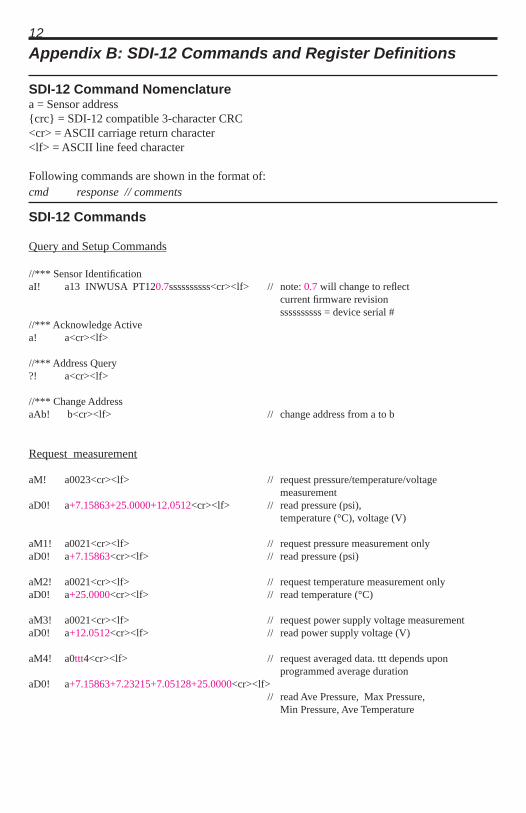
12Appendix B: SDI-12 Commands and Register Defi nitions
SDI-12 Command Nomenclaturea = Sensor address{crc} = SDI-12 compatible 3-character CRC<cr> = ASCII carriage return character<lf> = ASCII line feed character
Following commands are shown in the format of:cmd response // comments
SDI-12 Commands
Query and Setup Commands
//*** Sensor Identifi cationaI! a13 INWUSA PT120.7ssssssssss<cr><lf> // note: 0.7 will change to refl ect current fi rmware revision ssssssssss = device serial #//*** Acknowledge Activea! a<cr><lf>
//*** Address Query?! a<cr><lf>
//*** Change AddressaAb! b<cr><lf> // change address from a to b
Request measurement
aM! a0023<cr><lf> // request pressure/temperature/voltage measurementaD0! a+7.15863+25.0000+12.0512<cr><lf> // read pressure (psi), temperature (°C), voltage (V)
aM1! a0021<cr><lf> // request pressure measurement onlyaD0! a+7.15863<cr><lf> // read pressure (psi)
aM2! a0021<cr><lf> // request temperature measurement onlyaD0! a+25.0000<cr><lf> // read temperature (°C)
aM3! a0021<cr><lf> // request power supply voltage measurementaD0! a+12.0512<cr><lf> // read power supply voltage (V)
aM4! a0ttt4<cr><lf> // request averaged data. ttt depends upon programmed average durationaD0! a+7.15863+7.23215+7.05128+25.0000<cr><lf> // read Ave Pressure, Max Pressure, Min Pressure, Ave Temperature

13M5!, M6!, and M7! only available on PT12-BV/PT12 combination units!aM5! a0023<cr><lf> // request barometrically compensated down-hole pressure, down-hole temperature, surface temperature measurementaD0! a+2.58613+19.2100+21.0512<cr><lf> // read barometrically compensated down-hole pressure, down-hole temperature, surface temperature aM6! a0024<cr><lf> // request non-barometrically compensated down- hole pressure, down-hole temperature, surface pressure, surface temperature measurementaD0! a+17.31813+19.2100+14.732+21.0512<cr><lf> // read non-barometrically compensated down- hole pressure, down-hole temperature, surface pressure, surface temperature aM7! atttl<cr><lf> // request averaged, barometrically compensated pressure. ttt depends upon programmed averageaD0! a+7.12050<cr><lf> // averaged barometrically compensated pressure
Request measurement with CRC
aMC! a0023<cr><lf> // request pressure/temperature/voltage measurementaD0! a+7.15863+25.0000+12.0512{crc}<cr><lf> // read pressure (psi), temperature (°C), voltage (V)
aMC1! a0021<cr><lf> // request pressure measurement onlyaD0! a+7.15863{crc}<cr><lf> // read pressure (psi)
aMC2! a0021<cr><lf> // request temperature measurement onlyaD0! a+25.0000{crc}<cr><lf> // read temperature (°C)
aMC3! a0021<cr><lf> // request power supply voltage measurementaD0! a+12.0512{crc}<cr><lf> // read power supply voltage (V)
aMC4! a0ttt4<cr><lf> // request averaged data. ttt depends upon programmed average durationaD0! a+7.15863+7.23215+7.05128+25.0000{crc}<cr><lf> // read Ave Pressure, Max Pressure, Min Pressure, Ave Temperature
MC5!, MC6!, and MC7! only available on PT12-BV/PT12 combination units!aMC5! a0023<cr><lf> // request barometrically compensated down-hole pressure, down-hole temperature, surface temperature measurementaD0! a+2.58613+19.2100+21.0512{crc}<cr><lf> // read barometrically compensated down-hole pressure, down-hole temperature, surface

14
aMC6! a0024<cr><lf> // request non-barometrically compensated down- hole pressure, down-hole temperature, surface pressure, surface temperature measurementaD0! a+17.31813+19.2100+14.732+21.0512<cr><lf> // read non-barometrically compensated down- hole pressure, down-hole temperature, surface pressure, surface temperature aM7! atttl<cr><lf> // request averaged, barometrically compensated pressure. ttt depends upon programmed averageaD0! a+7.12050<cr><lf> // averaged barometrically compensated pressure
Concurrent measurement
aC! a00203<cr><lf> // request pressure/temperature/voltage measurementaD0! a+7.15863+25.0000+12.0512<cr><lf> // read pressure (psi), temperature (°C), voltage (V)
aC1! a00201<cr><lf> // request pressure measurement onlyaD0! a+7.15863 // read pressure (psi)
aC2! a00201<cr><lf> // request temperature measurement onlyaD0! a+25.0000<cr><lf> // read temperature (°C)
aC3! a00201<cr><lf> // request power supply voltage measurementaD0! a+12.0512<cr><lf> // read power supply voltage (V)
aC4! a0ttt04<cr><lf> // request averaged data. ttt depends upon programmed average durationaD0! a+7.15863+7.23215+7.05128+25.0000<cr><lf> // read Ave Pressure, Max Pressure, Min Pressure, Ave Temperature
C5!, C6!, and C7! only available on PT12-BV/PT12 combination units!aC5! a00203<cr><lf> // request barometrically compensated down-hole pressure, down-hole temperature, surface temperature measurementaD0! a+2.58613+19.2100+21.0512<cr><lf> // read barometrically compensated down-hole pressure, down-hole temperature, surface temperature aC6! a00204<cr><lf> // request non-barometrically compensated down- hole pressure, down-hole temperature, surface pressure, surface temperature measurementaD0! a+17.31813+19.2100+14.732+21.0512<cr><lf> // read non-barometrically compensated down- hole pressure, down-hole temperature, surface pressure, surface temperature aC7! attt01<cr><lf> // request averaged, barometrically compensated pressure. ttt depends upon programmed averageaD0! a+7.12050<cr><lf> // averaged barometrically compensated pressure

15Concurrent measurement with CRC
aCC! a00203<cr><lf> // request pressure/temperature/voltage measurementaD0! a+7.15863+25.0000+12.0512{crc}<cr><lf> // read pressure (psi), temperature (°C), voltage (V)
aCC1! a00201<cr><lf> // request pressure measurement onlyaD0! a+7.15863{crc}<cr><lf> // read pressure (psi)
aCC2! a00201<cr><lf> // request temperature measurement onlyaD0! a+25.0000{crc}<cr><lf> // read temperature (°C)
aCC3! a00201<cr><lf> // request power supply voltage measurementaD0! a+12.0512{crc}<cr><lf> // read power supply voltage (V)
aCC4! a0ttt04<cr><lf> // request averaged data. ttt depends upon programmed average durationaD0! a+7.15863+7.23215+7.05128+25.0000{crc}<cr><lf> // read Ave Pressure, Max Pressure, Min Pressure, Ave Temperature
CC5!, CC6!, and CC7! only available on PT12-BV/PT12 combination units!aCC5! a00203<cr><lf> // request barometrically compensated down-hole pressure, down-hole temperature, surface temperature measurementaD0! a+2.58613+19.2100+21.0512{crc}<cr><lf> // read barometrically compensated down-hole pressure, down-hole temperature, surface temperature aCC6! a00204<cr><lf> // request non-barometrically compensated down- hole pressure, down-hole temperature, surface pressure, surface temperature measurementaD0! a+17.31813+19.2100+14.732+21.0512{crc}<cr><lf> // read non-barometrically compensated down- hole pressure, down-hole temperature, surface pressure, surface temperature aCC7 attt01<cr><lf> // request averaged, barometrically compensated pressure. ttt depends upon programmed averageaD0! a+7.12050<cr><lf> // averaged barometrically compensated pressure

16Extended Commands
//*** Set duration for averaging readingaXAttt! attt<cr><lf> // set duration of averaged data for M4 command // ttt = 1..997 seconds
//*** Read/Modify Calibration ValuesaXCnn{=<value>}! a<value><cr><lf> // read{modify} calibration value nn
examples:aXC00! a+1.591600e-5<CR><LF> // read value of calibration register 00aXC00=1.704e-4! a+1.704000e-4<CR><LF> // set value of calibration register 00
//*** Set number of signifi cant digitsaXSt! at<cr><lf> // set # of signifi cant digits for SDI-12 report data // t = 1..7

17Calibration Register Defi nitionsAll calibration registers contain fl oating point values.SDI-12 DefaultREG ID Mnemonic Description Value ______________________________________________________________________________________ 00 Scale Units scale 1.591600E-5 (Counts * Scale = base units, default psi)
01 a Factory cal-linearized correction factor 1 0.000000E+00
02 b Factory cal-linearized correction factor 2 1.000000E+00
03 m0 Factory cal-slope coeffi cient 0 1.000000E+00
04 m1 Factory cal-slope coeffi cient 1 0.000000E+00
05 m2 Factory cal-slope coeffi cient 2 0.000000E+00
06 b0 Factory cal-offset coeffi cient 0 0.000000E+00
07 b1 Factory cal-offset coeffi cient 1 0.000000E+00
08 b2 Factory cal-offset coeffi cient 2 0.000000E+00
09 mField Field pressure cal-slope 1.000000E+00
10 bField Field pressure cal-offset 0.000000E+00
11 mT Field temperature cal-slope 1.000000E+00
12 bT Field temperature cal-offset 0.000000E+00
13 T_Alpha Factory Temperature Cal-Alpha 0.000000E+00
14 T_Offset Factory Temperature Cal-Offset 0.000000E+00
15 T_ZeroSlope Factory Temperature Cal-ZeroSlope 0.000000E+00
16 P_mUnits Pressure units conversion slope 1.000000E+00
17 P_bUnits Pressure units conversion offset 0.000000E+00
18 T_mUnits Temperature units conversion slope 1.000000E+00
19 T_bUnits Temperature units conversion offset 0.000000E+00
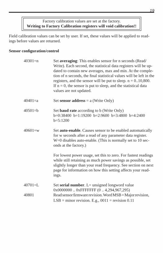
Factory calibration values are set at the factory. Writing to Factory Calibration registers will void calibration!!
Field calibration values can be set by user. If set, these values will be applied to read-ings before values are returned.
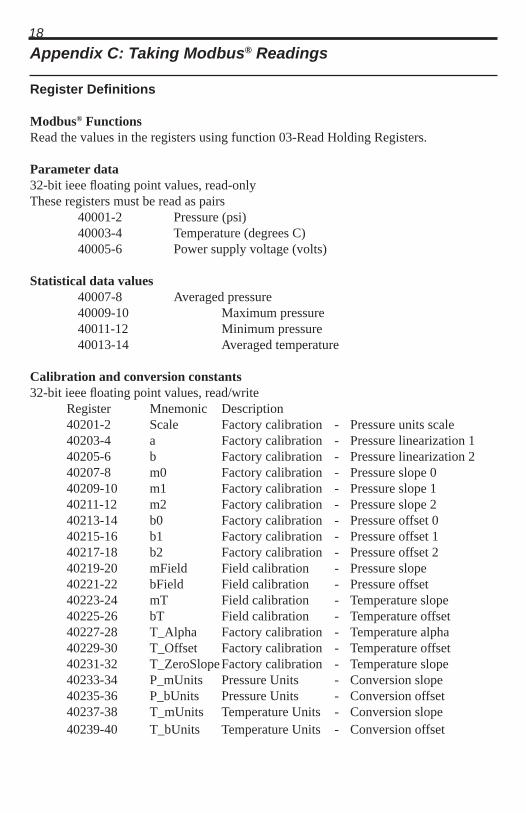
18Appendix C: Taking Modbus® Readings
Register Defi nitions
Modbus® FunctionsRead the values in the registers using function 03-Read Holding Registers.
Parameter data32-bit ieee fl oating point values, read-onlyThese registers must be read as pairs 40001-2 Pressure (psi) 40003-4 Temperature (degrees C) 40005-6 Power supply voltage (volts)
Statistical data values40007-8 Averaged pressure40009-10 Maximum pressure40011-12 Minimum pressure40013-14 Averaged temperature
Calibration and conversion constants32-bit ieee fl oating point values, read/write Register Mnemonic Description 40201-2 Scale Factory calibration - Pressure units scale 40203-4 a Factory calibration - Pressure linearization 1 40205-6 b Factory calibration - Pressure linearization 2 40207-8 m0 Factory calibration - Pressure slope 0 40209-10 m1 Factory calibration - Pressure slope 1 40211-12 m2 Factory calibration - Pressure slope 2 40213-14 b0 Factory calibration - Pressure offset 0 40215-16 b1 Factory calibration - Pressure offset 1 40217-18 b2 Factory calibration - Pressure offset 2 40219-20 mField Field calibration - Pressure slope 40221-22 bField Field calibration - Pressure offset 40223-24 mT Field calibration - Temperature slope 40225-26 bT Field calibration - Temperature offset 40227-28 T_Alpha Factory calibration - Temperature alpha 40229-30 T_Offset Factory calibration - Temperature offset 40231-32 T_ZeroSlope Factory calibration - Temperature slope 40233-34 P_mUnits Pressure Units - Conversion slope 40235-36 P_bUnits Pressure Units - Conversion offset 40237-38 T_mUnits Temperature Units - Conversion slope 40239-40 T_bUnits Temperature Units - Conversion offset
19
Factory calibration values are set at the factory. Writing to Factory Calibration registers will void calibration!!
Field calibration values can be set by user. If set, these values will be applied to read-ings before values are returned.
Sensor confi guration/control
40301=n Set averaging: This enables sensor for n seconds (Read/Write). Each second, the statistical data registers will be up-dated to contain new averages, max and min. At the comple-tion of n seconds, the fi nal statistical values will be left in the registers, and the sensor will be put to sleep. n = 0..10,800. If n = 0, the sensor is put to sleep, and the statistical data values are not updated.
40401=a Set sensor address = a (Write Only)
40501=b Set baud rate according to b (Write Only)b=0:38400 b=1:19200 b=2:9600 b=3:4800 b=4:2400 b=5:1200
40601=w Set auto-enable. Causes sensor to be enabled automatically for w seconds after a read of any parameter data register. W=0 disables auto-enable. (This is normally set to 10 sec-onds at the factory.)
For lowest power usage, set this to zero. For fastest readings while still retaining as much power savings as possible, set slightly longer than your read frequency. See section on next page for information on how this setting affects your read-ings.
40701=L Set serial number. L= unsigned longword value 0x0000000 .. 0xFFFFFFF (0 .. 4,294,967,295)40801 Read sensor fi rmware revision. Word MSB = Major revision,
LSB = minor revision. E.g., 0011 = revision 0.11
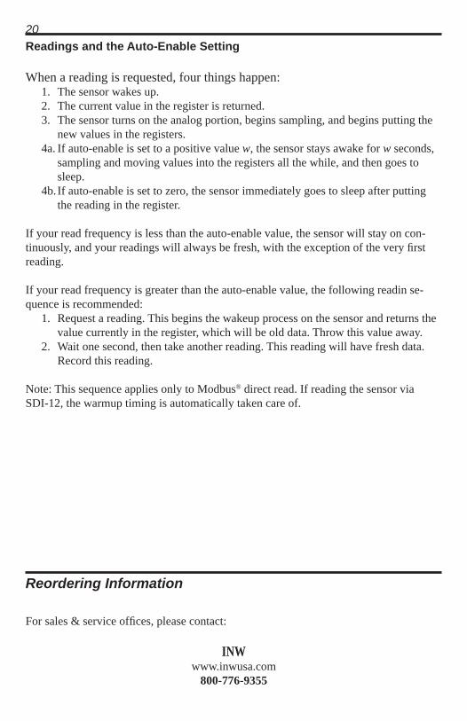
20Readings and the Auto-Enable Setting
When a reading is requested, four things happen: 1. The sensor wakes up. 2. The current value in the register is returned. 3. The sensor turns on the analog portion, begins sampling, and begins putting the
new values in the registers. 4a. If auto-enable is set to a positive value w, the sensor stays awake for w seconds,
sampling and moving values into the registers all the while, and then goes to sleep.
4b. If auto-enable is set to zero, the sensor immediately goes to sleep after putting the reading in the register.
If your read frequency is less than the auto-enable value, the sensor will stay on con-tinuously, and your readings will always be fresh, with the exception of the very fi rst reading.
If your read frequency is greater than the auto-enable value, the following readin se-quence is recommended:
1. Request a reading. This begins the wakeup process on the sensor and returns the value currently in the register, which will be old data. Throw this value away.
2. Wait one second, then take another reading. This reading will have fresh data. Record this reading.
Note: This sequence applies only to Modbus® direct read. If reading the sensor via SDI-12, the warmup timing is automatically taken care of.
Reordering Information
For sales & service offi ces, please contact:
INWwww.inwusa.com
800-776-9355

21LIMITED WARRANTY/DISCLAIMER - PT12 SUBMERSIBLE PRESSURE TRANSDUCER
A. Seller warrants that products manufactured by Seller when properly installed, used and maintained with a properly installed desiccant tube, shall be free from defects in material and workmanship. Seller’s obligation under this warranty shall be limited to replacing or repairing the part or parts or, at Seller’s option, the products which prove defective in material or workmanship within ONE (1) year from the date of delivery, provided that Buyer gives Seller prompt notice of any defect or failure and satisfactory proof thereof. Any defective part or parts must be returned to Seller’s factory or to an authorized service center for inspection. Buyer will prepay all freight charges to return any products to Seller’s factory, or any other repair facility designated by Seller. Seller will deliver replacements for defective products to Buyer (ground freight prepaid) to the destination provided in the original order. Products returned to Seller for which Seller provides replacement under this warranty shall become the property of Seller.
This limited warranty does not apply to lack of performance caused by abrasive materi-als, corrosion due to aggressive fl uids, mishandling or misapplication. Seller’s obliga-tions under this warranty shall not apply to any product which (a) is normally consumed in operation, or (b) has a normal life inherently shorter than the warranty period stated herein.
In the event that equipment is altered or repaired by the Buyer without prior written approval by the Seller, all warranties are void. Equipment and accessories not manu-factured by the Seller are warranted only to the extent of and by the original manufac-turer’s warranty.
THE FOREGOING WARRANTIES ARE IN LIEU OF ALL OTHER WARRAN-TIES, WHETHER ORAL, WRITTEN, EXPRESSED, IMPLIED OR STATUTORY. IMPLIED WARRANTIES OF FITNESS AND MERCHANTABILITY SHALL NOT APPLY. SELLER’S WARRANTY OBLIGATIONS AND BUYER’S REMEDIES THEREUNDER (EXCEPT AS TO TITLE) ARE SOLELY AND EXCLUSIVELY AS STATED HEREIN. IN NO CASE WILL SELLER BE LIABLE FOR CONSEQUEN-TIAL DAMAGES, LABOR PERFORMED IN CONNECTION WITH REMOVAL AND REPLACEMENT OF THE SENSOR SYSTEM, LOSS OF PRODUCTION OR ANY OTHER LOSS INCURRED BECAUSE OF INTERRUPTION OF SERVICE. A NEW WARRANTY PERIOD SHALL NOT BE ESTABLISHED FOR REPAIRED OR REPLACED MATERIAL, PRODUCTS OR SUPPLIES. SUCH ITEMS SHALL RE-MAIN UNDER WARRANTY ONLY FOR THE REMAINDER OF THE WARRANTY PERIOD ON THE ORIGINAL MATERIALS, PRODUCTS OR SUPPLIES.
(Continued on the next page)

22B. With respect to products purchased by consumers in the United States for personal use, the implied warranties including but not limited to the warranties of merchantabil-ity and fi tness for a particular purpose, are limited to twelve (12) months from the date of delivery.
Some states do not allow limitations on the duration of an implied warranty, so the above limitation may not apply to you. Similarly, some states do not allow the exclu-sion or limitation of consequential damages, so the above limitation or exclusion may not apply to you. This limited warranty gives you specifi c legal rights; however, you may also have other rights which may vary from state to state.

23Notes

24Notes

8902 122nd Avenue NEKirkland, WA 98033 USA 425-822-4434FAX 425-822-8384 / [email protected]
INW
©1997 - 2013 by Instrumentation Northwest, Inc. All rights reserved. Instrumentation Northwest and INW are trademarks registered with the U.S. Patent & Trademark Offi ce. Doc# 9B0007r10 10/24/2013 / PN 6D290-NI