Embed Size (px)
Citation preview

PROTECTED RESISTOR-GROUP Style. RFP
1. DESCRIPTION Even when the power to dissipate is not very high, in the dynamic braking it arises the requiring for a protected and compact resistor-group that may be employed like an independent unity. The resistor style RFP are studied to meet this exigency when the required load is between 300 W and 800 W The finishing surface of metallic box is zinc-galvanised. 2. GENERAL CHARACTERISTICS A resistor style SRF, mounted on a suitable heat sink, is arranged inside the box, and naturally the electrical characteristics of every group reflects the characteristics of the mounted resistor, that is to say:
LP
145
107
116
= =
=
=
Modello L-0+2 P±1RFP 600 153 80 RFP 900 193 120 RFP1300 243 170
Style used resistor RFP 600 SRF 600 RFP 900 SRF 900 RFP1300 SRF 1300
6,2
70
Approval Walter Cerutti Verified Mauro Pellegatta Revision 2 10/10/97 Emission DT 13.06.1997
N. 640380 foglio 1 di 2
DATA SHEET

The main characteristics for all the models are::
3 Graph Load/Box over temperature
4. ASSEMBLING INSTRUCTIONS
∆T °C
210
180
150
120
90
60
30
The correct mounting is vertical with outlet leaving upper side. With horizontal mounting apply a derating of 30% in order to avoid the cover overeating.
100 200 300 400 500 600 700 800 W
2.1 Dielectric strength (1’@ 50Hz) 3.000 Vrms. (resistor /Box) 2.2 Isolation resistance > 10.000 MΩ (@ 1000VDC) 2.3 Resistance range 2 ÷ 250 Ω2.4 Tolerance ± 5% 2.5 Protection grade IP21 2.6 Connecting clamps Resistor N° 2 of 4ž
Earth N° 1 Screw M4
RFP1300 RFP900RFP600
Approval Walter Cerutti Verified Mauro Pellegatta Revision 2 10/10/97 Emission DT 13.06.1997
N. 640380 foglio 2 di 2
DATA SHEET

VENTILATED RESISTORS GROUP mod. BUV 1 (4000 W max)
1. DESCRIPTION Frequently, in dynamic braking, when the continuous power is higher than 1000 W, it arises the requirement of a ventilated and protected resistors group that may be employed like an independent unit. The resistors group type BUV 1 & BUV 2 (see Data Sheet 64240) are studied to meet this need, when the required load is between 1000 and 8000 W. The finishing surface of the metallic box is zinc-galvanised, but it is possible to receive the varnished version. 2. GENERAL CHARACTERISTICS A resistors group, suitable to stand the required load or impulse duty cycle, is mounted in the ventilated box. The following characteristics are common to all models.
425 150
145
180305
160Connectingclamps area
Resistors Area
Ventilator
2.1 Dielectric strength (1’@ 50Hz) 4.500 Vrms. (resistors/box) 3.000 Vrms. (Auxiliaries Clamps/box)
2.2 Isolation resistance (@ 1000V) > 10.000 MΩ2.3 Resistance range 2 ÷ 10.000 Ω2.4 Tolerance ± 5% 2.5 Connecting clamps Resistor N° 2 of 6
Ventilator N° 2 of 4Thermostat (on request) N° 2 of 4Earth N° 1 of 6
Approval Walter Cerutti Verified Mauro Pellegatta Revision 0 12.03.96 Emission DT 12.03.96
N. 640230 foglio 1 di 2
DATA SHEET
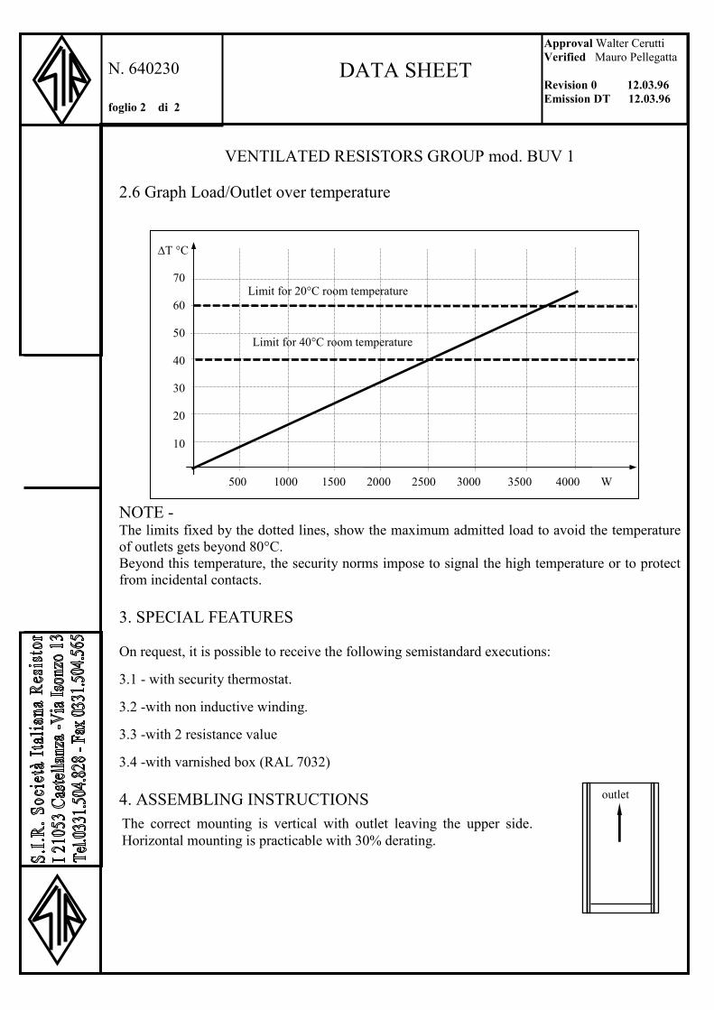
VENTILATED RESISTORS GROUP mod. BUV 1 2.6 Graph Load/Outlet over temperature
NOTE - The limits fixed by the dotted lines, show the maximum admitted load to avoid the temperature of outlets gets beyond 80°C. Beyond this temperature, the security norms impose to signal the high temperature or to protect from incidental contacts.
3. SPECIAL FEATURES On request, it is possible to receive the following semistandard executions: 3.1 - with security thermostat. 3.2 -with non inductive winding. 3.3 -with 2 resistance value 3.4 -with varnished box (RAL 7032) 4. ASSEMBLING INSTRUCTIONS
500 1000 1500 2000 2500 3000 3500 4000 W
∆T °C
70
60
50
40
30
20
10
Limit for 20°C room temperature
Limit for 40°C room temperature
500 1000 1500 2000 2500 3000 3500 4000 W
The correct mounting is vertical with outlet leaving the upper side. Horizontal mounting is practicable with 30% derating.
outlet
Approval Walter Cerutti Verified Mauro Pellegatta Revision 0 12.03.96 Emission DT 12.03.96
N. 640230 foglio 2 di 2
DATA SHEET
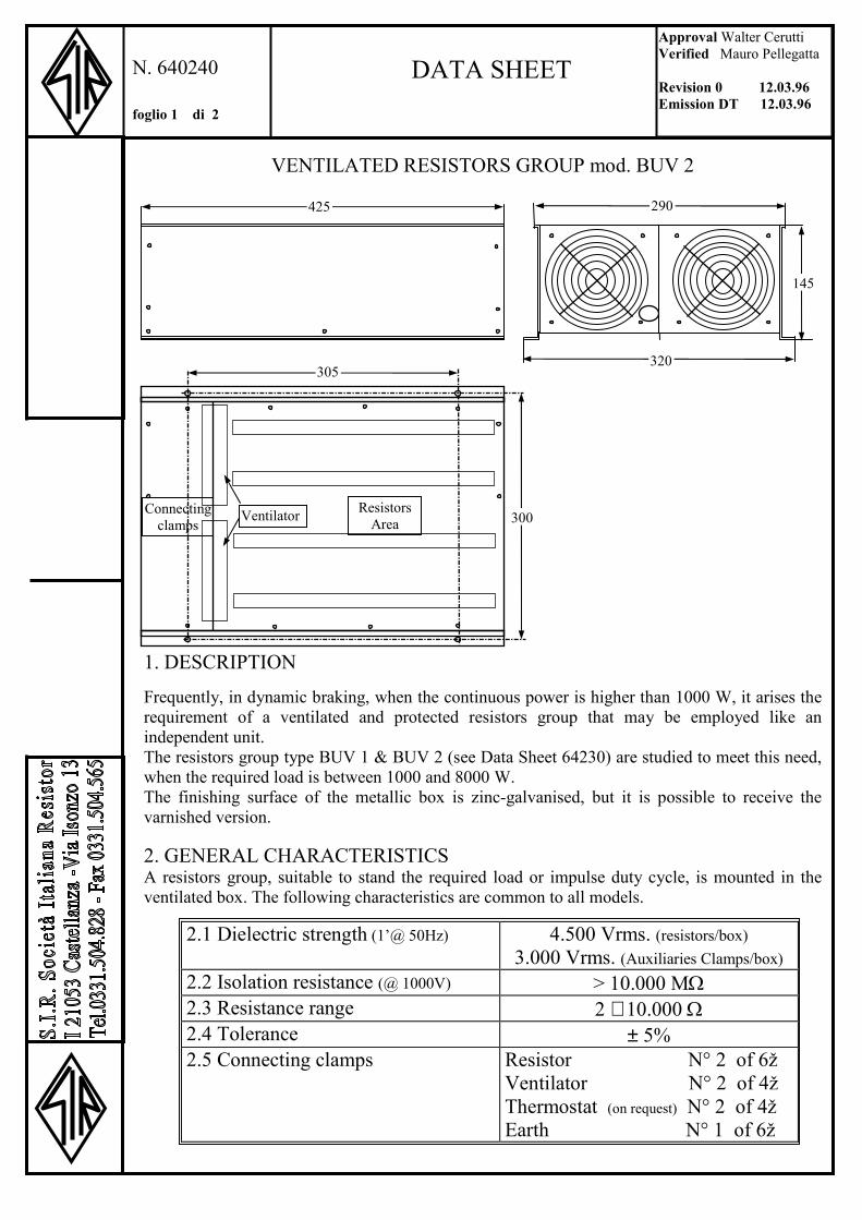
VENTILATED RESISTORS GROUP mod. BUV 2
1. DESCRIPTION Frequently, in dynamic braking, when the continuous power is higher than 1000 W, it arises the requirement of a ventilated and protected resistors group that may be employed like an independent unit. The resistors group type BUV 1 & BUV 2 (see Data Sheet 64230) are studied to meet this need, when the required load is between 1000 and 8000 W. The finishing surface of the metallic box is zinc-galvanised, but it is possible to receive the varnished version. 2. GENERAL CHARACTERISTICS A resistors group, suitable to stand the required load or impulse duty cycle, is mounted in the ventilated box. The following characteristics are common to all models.
2.1 Dielectric strength (1’@ 50Hz) 4.500 Vrms. (resistors/box) 3.000 Vrms. (Auxiliaries Clamps/box)
2.2 Isolation resistance (@ 1000V) > 10.000 MΩ2.3 Resistance range 2 ÷ 10.000 Ω2.4 Tolerance ± 5% 2.5 Connecting clamps Resistor N° 2 of 6ž
Ventilator N° 2 of 4ž Thermostat (on request) N° 2 of 4ž Earth N° 1 of 6ž
290
320
425
145
Resistors Area
Connectingclamps
Ventilator
145
300
305
Approval Walter Cerutti Verified Mauro Pellegatta Revision 0 12.03.96 Emission DT 12.03.96
N. 640240 foglio 1 di 2
DATA SHEET
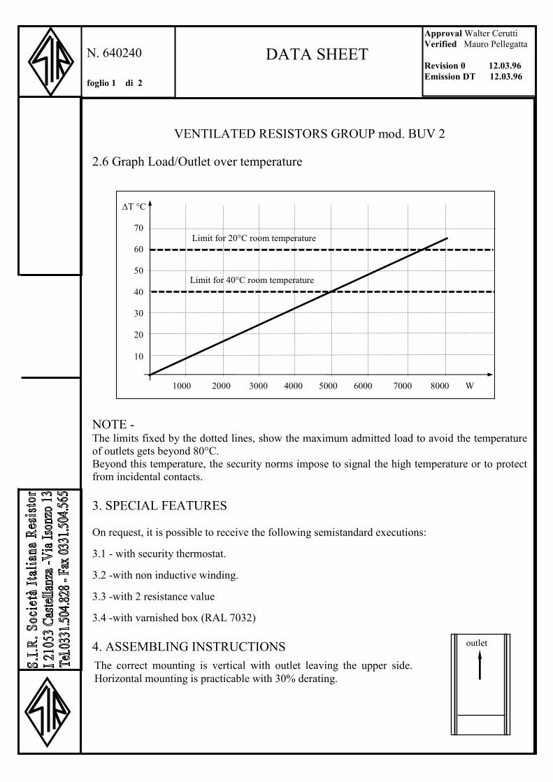
VENTILATED RESISTORS GROUP mod. BUV 2 2.6 Graph Load/Outlet over temperature
NOTE - The limits fixed by the dotted lines, show the maximum admitted load to avoid the temperature of outlets gets beyond 80°C. Beyond this temperature, the security norms impose to signal the high temperature or to protect from incidental contacts.
3. SPECIAL FEATURES On request, it is possible to receive the following semistandard executions: 3.1 - with security thermostat. 3.2 -with non inductive winding. 3.3 -with 2 resistance value 3.4 -with varnished box (RAL 7032) 4. ASSEMBLING INSTRUCTIONS
500 1000 1500 2000 2500 3000 3500 4000 W
∆T °C
70
60
50
40
30
20
10
Limit for 20°C room temperature
Limit for 40°C room temperature
1000 2000 3000 4000 5000 6000 7000 8000 W
The correct mounting is vertical with outlet leaving the upper side. Horizontal mounting is practicable with 30% derating.
outlet
Approval Walter Cerutti Verified Mauro Pellegatta Revision 0 12.03.96 Emission DT 12.03.96
N. 640240 foglio 1 di 2
DATA SHEET

VENTILATED RESISTORS GROUP mod. BRU
BRU H L1 L2 P A B
21K 650 550 590 340 490 16016K 650 550 590 340 490 16014K 540 440 480 340 490 16010K 540 440 480 340 490 160
1. DESCRIPTION Frequently, in dynamic braking, when the continuous power is higher than 1000 W, the requirement of a ventilated and protected resistors group that may be employed like an independent unit, arises. The resistors group type BUV 1 & BUV 2 (see Data Sheet 64230&64240) are studied to meet this need, when the required load is between 1000 and 8000 W. In the case higher loads were required, the correct solution could be the groups of resistors BRU style. The finishing surface of the metallic box is varnished with RAL 7032 colour
2. GENERAL CHARACTERISTICS A resistors group, suitable to stand the required load or impulse duty cycle, is mounted in the ventilated box. The following characteristics are common to all models.
2.1 Dielectric strength (1’@ 50Hz) 4.500 Vrms. (resistors/box) 3.000 Vrms. (Auxiliaries Clamps/box)
2.2 Isolation resistance (@ 1000V) > 10.000 MΩ2.3 Resistance range 2 ÷ 10.000 Ω2.4 Tolerance ± 5% 2.5 Connecting clamps Resistor N° 2 of 6 mm2
Ventilator N° 2 of 4 mm2
Thermostat N° 2 of 4 mm2
Earth N° 1 of 6 mm2
=
H
=
A
B
L1L250 P
L2 - 20
Pierced plate diaphragm n°12 Screws
6,5 x 12
Approval Walter Cerutti Verified Mauro Pellegatta Revision 0 12.3.1996 Emission DT 12.3.1996
N. . 640250 foglio 1 di 1
DATA SHEET

VENTILATED RESISTORS GROUP mod. BRU 2.6 Graph Load/Outlet over temperature
NOTE - The limits fixed by the dotted lines, show the maximum admitted load to avoid the temperature of outlets to arise beyond 80°C. Beyond this temperature, the security norms impose to signal the high temperature or to protect from incidental contacts.
3. SPECIAL FEATURES On request, it is possible to receive the following semistandard executions: 3.1 - with security thermostat (recommended). 3.2 -with non inductive winding. 3.3 -with more resistance values
4. ASSEMBLING INSTRUCTIONS
500 1000 1500 2000 2500 3000 3500 4000 W
∆T °C
70
60
50
40
30
20
10
Limit for 20°C room temperature
Limit for 40°C room temperature
3000 6000 9000 12000 15000 18000 21000 24000 W
The correct mounting is vertical with outlet leaving the upper side. Horizontal mounting is not practicable.
BRU16K BRU21KBRU14K
BRU10K
Approval Walter Cerutti Verified Mauro Pellegatta Revision 0 12.3.1996 Emission DT 12.3.1996
N. . 640250 foglio 2 di 2
DATA SHEET
.
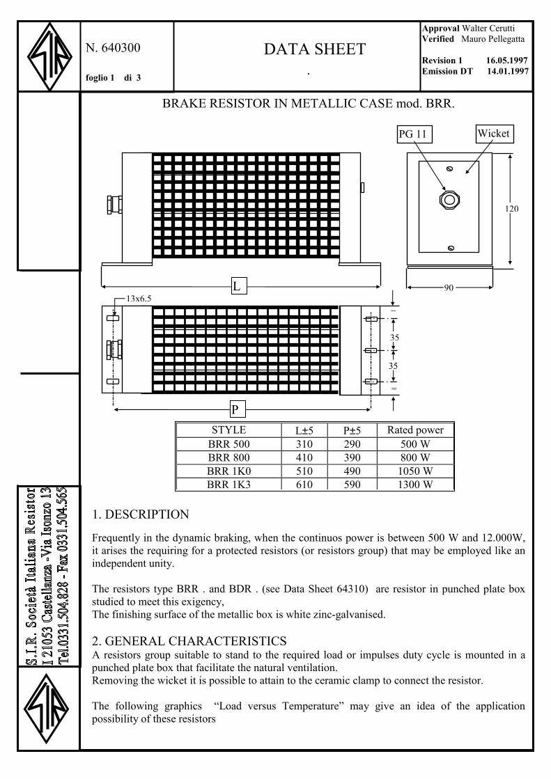
BRAKE RESISTOR IN METALLIC CASE mod. BRR.
1. DESCRIPTION Frequently in the dynamic braking, when the continuos power is between 500 W and 12.000W, it arises the requiring for a protected resistors (or resistors group) that may be employed like an independent unity. The resistors type BRR . and BDR . (see Data Sheet 64310) are resistor in punched plate box studied to meet this exigency, The finishing surface of the metallic box is white zinc-galvanised. 2. GENERAL CHARACTERISTICS A resistors group suitable to stand to the required load or impulses duty cycle is mounted in a punched plate box that facilitate the natural ventilation. Removing the wicket it is possible to attain to the ceramic clamp to connect the resistor. The following graphics “Load versus Temperature” may give an idea of the application possibility of these resistors
PG 11 Wicket
STYLE L±5 P±5 Rated power BRR 500 310 290 500 W BRR 800 410 390 800 W BRR 1K0 510 490 1050 W BRR 1K3 610 590 1300 W
L
P
120
90
=
35
35
=
13x6,5
Approval Walter Cerutti Verified Mauro Pellegatta Revision 1 16.05.1997Emission DT 14.01.1997
N. 640300 foglio 1 di 3
DATA SHEET

.
BRAKE RESISTOR IN METALLIC CASE mod. BRR. Other main caracteristics are:
2.6 Graph Load/Protection grid temperature
2.7 Graph Load/Outlet over temperature
2.1 Dielectric strength (1’@ 50Hz) 4.500 rms (resistors/box) 2.2 Isolation resistance (@ 1000V) > 10.000 MΩ2.3 Resistance range 2 ÷ 10.000 Ω2.4 Tolerance ± 5%2.4 Overload 5 times the rated power for 10” 2.6Connecting clamps (ceramic) Resistor N° 2 of 4mm2
Earth N° 1 Screw M4
∆T °C
90
80
70
60
50
40
30
Limit for 20°C room temperature
Limit for 40°C room temperature
200 400 600 800 1000 1200 1400 1600 W
∆T °C
180
160
140
120
100
80
60
200 400 600 800 1000 1200 1400 1600 W
BRR 500
BRR 500
BRR 800
BRR 800
BRR 1K3
BRR 1K3
BRR 1K0
BRR 1K0
Approval Walter Cerutti Verified Mauro Pellegatta Revision 1 16.05.1997Emission DT 14.01.1997
N. 640300 foglio 2 di 3
DATA SHEET

.
BRAKE RESISTOR IN METALLIC CASE mod. BRR
NOTE - The limits fixed by the dotted lines, show the maximum admitted load to avoid the temperature of outlets arises beyond 80°C. Over this temperature the security norms impose to signal the high temperature or to protect by the incidental contacts.
2.8 Graph Overload/Application time
3. SPECIAL FEATURES On request it is possible to achieve the following semistandard executions: 3.1 - with security thermostat (e.g. BRR500T) 3.2 -with non inductive winding. (e.g. BRRN500) 3.3 -with two resistance values (e.g. BRRP500)
4. ASSEMBLING INSTRUCTIONS The correct mounting is Horizontal . Vertical mounting is not practicable.
W
20.000
18.000
16.000
14.000
12.000
10.000
8.000
6.000
4.000
2.000
2 4 6 8 10 20 40 60 80 100 sec.
BRR 1300
BRR 500
BRR 800
BRR 1000
Approval Walter Cerutti Verified Mauro Pellegatta Revision 1 16.05.1997Emission DT 14.01.1997
N. 640300 foglio 3 di 3
DATA SHEET

.
BRAKE RESISTOR IN METALLIC CASE mod. BDR.
1. DESCRIPTION Frequently in the dynamic braking, when the continuos power is between 500 W and 12.000W, it arises the requiring for a protected resistors (or resistors group) that may be employed like an independent unity. The resistors type BRR . and BDR . (see Data Sheet 64300) are resistor in punched plate box studied to meet this exigency, The finishing surface of the metallic box is white zinc-galvanised. 2. GENERAL CHARACTERISTICS A resistors group suitable to stand to the required load or impulses duty cycle is mounted in a punched plate box that facilitate the natural ventilation. Removing a side it is possible to attain to the clamp to connect the resistor.
STYLE L±3 B P Rated power BDR 2K0 498 100 40 2.500 W BDR 4K0 625 100 40 4000 W BDR 8K0 625 160 60 8000 W BDR 12K0 625 200 80 12000 W
L
P
P
250
=
=
PG 7* PG 11/PG16
13x6,5
* PG7 on version with thermostat only
B
L - 20
Approval Walter Cerutti Verified Mauro Pellegatta Revision 2 04/07/99 Emission DT 14/01/97
N. 640310 Page 1 of 3
DATA SHEET

.
BRAKE RESISTOR IN METALLIC CASE mod. BDR. The main characteristics are:
The following graphics “Load versus Temperature” may give an idea of the application possibility of these resistors
2.6 Graph Load/Protection grid over temperature
2.7 Graph Load/Outlet over temperature
2.1 Dielectric strength (1’@ 50Hz) 4.500 rms (resistors/box) 2.2 Isolation resistance (@ 1000V) > 10.000 MΩ2.3 Resistance range 2 ÷ 150 Ω2.4 Tolerance ± 5%2.4 Overload 5 times the rated power for 10” 2.6Connecting clamps (on resistor) Resistor N° 2 M5 screw
Earth N° 1 M4 screw
500 1000 1500 2000 2500 3000 3500 4000 W
∆T °C
160
140
120
100
80
60
40 Limit for 20°C room temperature
Limit for 40°C room temperature
1000 2000 4000 6000 8000 10000 12000 W
∆T °C
200
180
160
140
120
100
80
0 1000 2000 4000 6000 8000 10000 12000 W
BDR 4K0
BDR 4K0
BDR 8K0
BDR 8K0
BDR 12K0
BDR 12K0
Deck
Side
Approval Walter Cerutti Verified Mauro Pellegatta Revision 2 04/07/99 Emission DT 14/01/97
N. 640310 Page 2 of 3
DATA SHEET
BDR 2K0
BDR 2K0

.
BRAKE RESISTOR IN METALLIC CASE mod. BDR
NOTE - The limits fixed by the dotted lines, show the maximum admitted load to avoid the temperature of outlets gets beyond 80°C. Over this temperature the security norms impose to signal the high temperature or to protect by the incidental contacts.
2.8 Graph Overload/Application time
3. SPECIAL FEATURES On request it is possible to achieve the following semistandard executions: 3.1 - with security thermostat (e.g. BDR4K0T) 3.2 -with non inductive winding. (e.g. BRRN4K0) 3.3 -with more resistance values (e.g. BDRP4K0)
4. ASSEMBLING INSTRUCTIONS The correct mounting is Horizontal . Vertical mounting is not practicable.
W
90.000
81.000
72.000
63.000
54.000
45.000
36.000
27.000
18.000
9.000
2 4 6 8 10 20 40 60 80 100 sec.
BDR 12K0
BDR 8K0
BDR 4K0
Depending from resistance value
Approval Walter Cerutti Verified Mauro Pellegatta Revision 2 04/07/99 Emission DT 14/01/97
N. 640310 Page 3 of 3
DATA SHEET
BDR 2K0

.
BRAKE RESISTOR IN METALLIC CASE mod. BDC.
1. DESCRIPTION These types of resistor groups have the same dimensions of the corresponding series BDR (see data sheet 640310) The only difference is in the types of resistors employed to compose the group. These resistors are cemented types in order to reduce the noise caused from the brake current. The other general characteristics remain the same, as shown in the following table and graphics 2. GENERAL CHARACTERISTICS
3. SPECIAL FEATURES
On request it is possible to achieve the execution with security thermostat (e.g. BDC4K0T)
4. ASSEMBLING INSTRUCTIONS
The correct mounting is Horizontal. Vertical mounting is not practicable
5. Graph Load/Protection grid over temperature The limits fixed by the dotted lines, show the maximum admitted load to avoid the temperature of outlets arises beyond 80°C. Over this temperature the security norms impose to signal the high temperature or to protect by the incidental contacts.
STYLE L±3 B P PG Style Max Power BDC 2K0 498 100 40 11 2.200 W BDC 4K0 625 100 40 11 4000 W BDC 8K0 625 160 60 11 7000 W BDC 12K0 625 200 80 16 10000 W
Approval Walter Cerutti Verified Mauro Pellegatta Revision 1 11/06/01 Emission DT 24/05/01
N. 640820 Page 1 of 2
DATA SHEET
2.1 Dielectric strength (1min @ 50Hz) 4.500 Vrms (resistors/box) 2.2 Isolation resistance (@ 1000V) > 10.000 MΩ2.3 Resistance range 2 ÷ 1000 Ω
Note: the rated power go down if the resistance value increase over 100 Ω
2.4 Tolerance ± 5%2.5 Overload See graph 6
L
P
P
250
=
=
13x6,5
*PG7 on version with thermostat only
B
L - 20
PG 11/16PG 7*

.
BRAKE RESISTOR IN METALLIC CASE mod. BDC.
5 Graph Load/Outlet over temperature
6 Graph Overload/Application time
.
Approval Walter Cerutti Verified Mauro Pellegatta Revision 1 11/06/01 Emission DT 24/05/01
N. 640820 Page 2 of 2
DATA SHEET
∆T °C200
180
160
140
120
100
80
0 1000 2000 4000 6000 8000 10000 12000 W
BDC 4K0 BDC 8K0 BDC 12K0BDC 2K0
∆T °C
160
140
120
100
80
60
40 Limit for 20°C room temperature
Limit for 40°C room temperature 1000 2000 4000 6000 8000 10000 12000 W
BDC 4K0 BDC 8K0 BDC 12K0
Deck
Side
BDC 2K0
W
90.000 81.000 72.000 63.000 54.000 45.000 36.000 27.000 18.000
9.000
2 4 6 8 10 20 40 60 80 100 sec.
BDC 12K0
BDC 8K0
BDC 4K0
Depending from resistance value
BDC 2K0
.
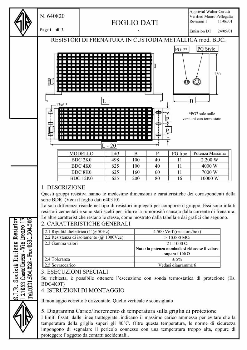
RESISTORI DI FRENATURA IN CUSTODIA METALLICA mod. BDC.
1. DESCRIZIONE Questi gruppi resistivi hanno le medesime dimensioni e caratteristiche dei corrispondenti della serie BDR (Vedi il foglio dati 640310) La sola differenza risiede nel tipo di resistori impiegati per comporre il gruppo. Essi sono infatti resistori cementati e sono stati scelti per ridurre la rumorosità causata dalla corrente di frenatura. Le altre caratteristiche restano le stesse, come mostrato dalla tabella e dai grafici che seguono. 2. CARATTERISTICHE GENERALI
3. ESECUZIONI SPECIALI Su richiesta, è possibile ottenere l’esecuzione con sonda termostatica di protezione (Es. BDC4K0T) 4. ISTRUZIONI DI MONTAGGIO
Il montaggio corretto è orizzontale. Quello verticale è sconsigliato
5. Diagramma Carico/Incremento di temperatura sulla griglia di protezione I limiti fissati dalle linee tratteggiate, indicano il massimo carico ammesso per evitare che la temperatura della griglia superi gli 80°C. Oltre questa temperatura, le norme di sicurezza impongono di segnalare il pericolo connesso con una temperatura troppo alta, oppure di proteggere l’oggetto da contatti accidentali..
MODELLO L±3 B P PG tipo Potenza Massima BDC 2K0 498 100 40 11 2.200 W BDC 4K0 625 100 40 11 4000 W BDC 8K0 625 160 60 11 7000 W BDC 12K0 625 200 80 16 10000 W
Approval Walter Cerutti Verified Mauro Pellegatta Revision 1 11/06/01 Emission DT 24/05/01
N. 640820 Page 1 di 2
FOGLIO DATI
2.1 Rigidità dielettrica (1’@ 50Hz) 4.500 Veff (resistors/box) 2.2 Resistenza di isolamento (@ 1000Vcc) > 10.000 MΩ2.3 Gamma valori 2 ÷ 1000 Ω
Nota: la potenza nominale si riduce se il valore supera i 100 Ω
2.4 Toleranza ± 5%2.5 Sovraccarico Vedasi diagramma 6
L
P
P
250
=
=
13x6,5
*PG7 solo sulle versioni con termostato
B
L - 20
PG StylePG 7*

.
RESISTORI DI FRENATURA IN CUSTODIA METALLICA mod. BDC
5. Diagramma Carico/Incremento di temperatura dell’aria in uscita
6 Diagramma Sovraccarico/Tempo di inserzione
.
Approval Walter Cerutti Verified Mauro Pellegatta Revision 1 11/06/01 Emission DT 24/05/01
N. 640820 Page 2 di 2
FOGLIO DATI
∆T °C200
180
160
140
120
100
80
0 1000 2000 4000 6000 8000 10000 12000 W
BDC 4K0 BDC 8K0 BDC 12K0BDC 2K0
∆T °C
160
140
120
100
80
60
40 limite per temperatura ambiente di 20°C
limite per temperatura ambiente di 40°C1000 2000 4000 6000 8000 10000 12000 W
BDC 4K0 BDC 8K0 BDC 12K0
Tetto
Fianchi
BDC 2K0
W
90.000 81.000 72.000 63.000 54.000 45.000 36.000 27.000 18.000
9.000
2 4 6 8 10 20 40 60 80 100 sec.
BDC 12K0
BDC 8K0
BDC 4K0
In funzione del valore di resistenza
BDC 2K0

.
BRAKE RESISTOR IN METALLIC CASE mod. BDR.
1. DESCRIPTION Frequently in the dynamic braking, when the continuos power is between 500 W and 12.000W, it arises the necessity of a protected resistors (or resistors group) that may be employed like an independent unity. The resistors type BRR are resistor with a metallic case, giving an IP23 protection grade, studied to meet this exigency. The finishing surface of the metallic box is white zinc-galvanised but is possible to achieve the varnished version (RAL7032).
2. GENERAL CHARACTERISTICS A resistors group suitable to stand to the required load or impulses duty cycle is mounted in a metallic case equipped with protected opening suitable to facilitate the natural ventilation.Removing a side it is possible to attain to the clamp to connect the resistor.
STYLE L M P Rated powerBDR 4K1 100 140 40 4000 W BDR 8K1 160 200 60 8000 W BDR 12K1 200 240 80 12000 W
=
=
602,5±3
P
P
13x6,5
625±5
588±2
L
PG 11/16PG 7*M
290±3
*PG7 on version with thermostat only
Approval Walter Cerutti Verified Mauro Pellegatta Revision 1 16.05.1997 Emission DT 14.01.1997
N. 640330 foglio 1 di 3
DATA SHEET
.
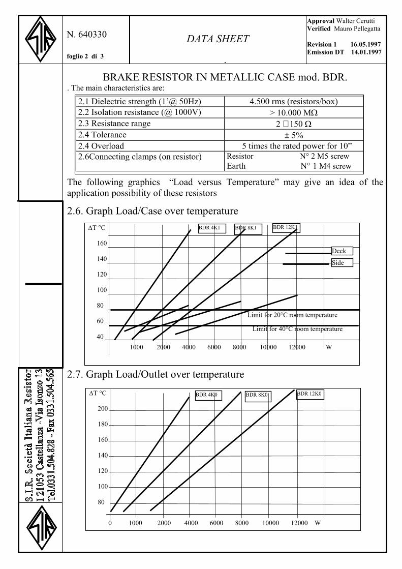
BRAKE RESISTOR IN METALLIC CASE mod. BDR. . The main characteristics are:
The following graphics “Load versus Temperature” may give an idea of the application possibility of these resistors
2.6. Graph Load/Case over temperature
2.7. Graph Load/Outlet over temperature
Approval Walter Cerutti Verified Mauro Pellegatta Revision 1 16.05.1997 Emission DT 14.01.1997
N. 640330 foglio 2 di 3
DATA SHEET
500 1000 1500 2000 2500 3000 3500 4000 W
∆T °C
160
140
120
100
80
60
40
Limit for 20°C room temperature
Limit for 40°C room temperature
1000 2000 4000 6000 8000 10000 12000 W
BDR 4K1 BDR 8K1 BDR 12K1
Deck
Side
∆T °C
200
180
160
140
120
100
80
0 1000 2000 4000 6000 8000 10000 12000 W
BDR 4K0 BDR 8K0 BDR 12K0
2.1 Dielectric strength (1’@ 50Hz) 4.500 rms (resistors/box) 2.2 Isolation resistance (@ 1000V) > 10.000 MΩ2.3 Resistance range 2 ÷ 150 Ω2.4 Tolerance ± 5% 2.4 Overload 5 times the rated power for 10” 2.6Connecting clamps (on resistor) Resistor N° 2 M5 screw
Earth N° 1 M4 screw

BRAKE RESISTOR IN METALLIC CASE mod. BDR
NOTE - The limits fixed by the dotted lines, show the maximum admitted load to avoid the temperature of case arises beyond 80°C. Over this temperature the security norms impose to signal the high temperature or to protect by the incidental contacts.
2.8 Graph Overload/Application time
3. SPECIAL FEATURES On request it is possible to achieve the following semistandard executions: 3.1 - with security thermostat (e.g. BDR4K1T) 3.2 -with non inductive winding. (e.g. BRRN4K1) 3.3 -with more resistance values (e.g. BDRP4K1)
4. ASSEMBLING INSTRUCTIONS The correct mounting is Horizontal .Vertical mounting is not practicable.
Approval Walter Cerutti Verified Mauro Pellegatta Revision 1 16.05.1997 Emission DT 14.01.1997
N. 640330 foglio 3 di 3
DATA SHEET
W
90.000
81.000
72.000
63.000
54.000
45.000
36.000
27.000
18.000
9.000
2 4 6 8 10 20 40 60 80 100 sec.
BDR 12K1
BDR 8K1
BDR 4K1
Depending from resistance value
BDR 2K1

Brake resistor in metallic case for wall Mounting Style BDV
1. FEATURE The BDV resistors are groups of resistance in metallic case, zinc plated, giving the protection grade of IP 20. The resistor is suitable for the wall mounting. They are studied in particular to support heavy duty-cycle with long ON time.
2. MAIN CHARACTERISTICS
3. SPECIAL FEATURES 3.1 – with security thermostat (e.g. BDV4K0T) 3.2 – with more resistance values (e.g. BDVP4K0)
4. ASSEMBLING INSTRUCTION The correct mounting is Vertical Horizontal mounting is not practicable
Approval Walter Cerutti Verified Mauro Pellegatta Revision 1 02.08.01 Emission DT 10/11/00
N. 640740 foglio 1 di 1
DATA SHEET
6,5x13 =
=
=
=
L+30
L
H
D
PG11 PG7* *PG7 only in the version with thermostat
P
DIMENSION Duty Cycle Overload(Time=sec)STYLE H mm±5 L mm±5 D mm±5 P mm±2
Rated Power 12 ON/240 OFF 60 ON/60 OFF
BDV 1K0 290 170 100 240 1.000W 8000 W 2000 W BDV 2K0 290 170 170 240 2.000W 15.000 W 3.800 W BDV 3K0 380 170 170 320 3.000 W 18.000 W 5.500 W BDV 4K0 450 220 170 390 4.000 W 20.000 W 6.000 W BDV 5K0 450 220 170 390 5.000 W 24.000 W 7.500 W BDV 8K0 610 350 220 500 8.000 W 45.000 W 12.000 W
BDV 10K0 610 350 220 500 10.000 W 50.000 W 15.000 W BDV 15K0 610 350 220 500 15.000 W 80.000.W 25.000 W
2.1 Dielectric strength (1 min @ 50 Hz) 3.500 Vrms (resistor/case) 2.2 Isolation resistance (@ 1000VDC) > 1.000 MΩ2.3 Resistance range 2÷150 Ω2.3 Resistance tolerance ±5%
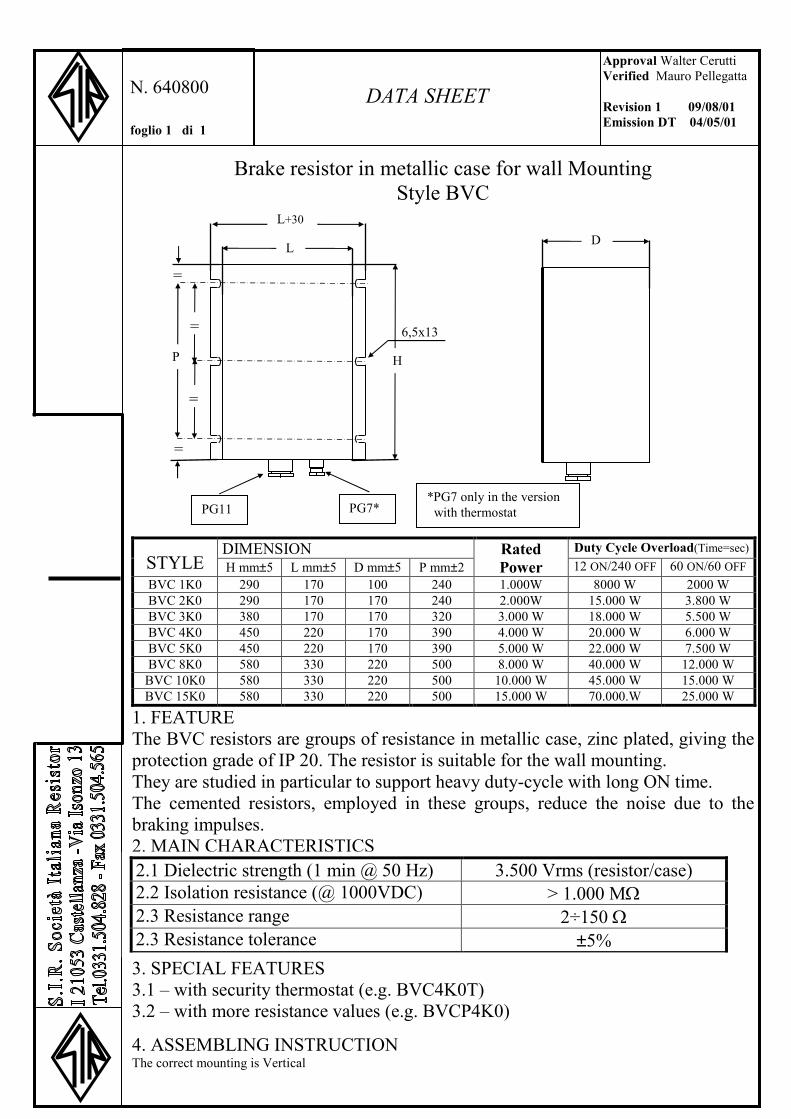
Brake resistor in metallic case for wall Mounting Style BVC
1. FEATURE The BVC resistors are groups of resistance in metallic case, zinc plated, giving the protection grade of IP 20. The resistor is suitable for the wall mounting. They are studied in particular to support heavy duty-cycle with long ON time. The cemented resistors, employed in these groups, reduce the noise due to the braking impulses. 2. MAIN CHARACTERISTICS
3. SPECIAL FEATURES 3.1 – with security thermostat (e.g. BVC4K0T) 3.2 – with more resistance values (e.g. BVCP4K0)
4. ASSEMBLING INSTRUCTION The correct mounting is Vertical
Approval Walter Cerutti Verified Mauro Pellegatta Revision 1 09/08/01 Emission DT 04/05/01
N. 640800 foglio 1 di 1
DATA SHEET
6,5x13 =
=
=
=
L+30
L
H
D
PG11 PG7* *PG7 only in the version with thermostat
P
DIMENSION Duty Cycle Overload(Time=sec)STYLE H mm±5 L mm±5 D mm±5 P mm±2
Rated Power 12 ON/240 OFF 60 ON/60 OFF
BVC 1K0 290 170 100 240 1.000W 8000 W 2000 W BVC 2K0 290 170 170 240 2.000W 15.000 W 3.800 W BVC 3K0 380 170 170 320 3.000 W 18.000 W 5.500 W BVC 4K0 450 220 170 390 4.000 W 20.000 W 6.000 W BVC 5K0 450 220 170 390 5.000 W 22.000 W 7.500 W BVC 8K0 580 330 220 500 8.000 W 40.000 W 12.000 W
BVC 10K0 580 330 220 500 10.000 W 45.000 W 15.000 W BVC 15K0 580 330 220 500 15.000 W 70.000.W 25.000 W
2.1 Dielectric strength (1 min @ 50 Hz) 3.500 Vrms (resistor/case) 2.2 Isolation resistance (@ 1000VDC) > 1.000 MΩ2.3 Resistance range 2÷150 Ω2.3 Resistance tolerance ±5%

BRAKE RESISTOR IN METALLIC CASE mod. BDR.
1. DESCRIPTION When in the dynamic braking, the required continuos power is beyond 12.000W, it is necessary a protected resistors group that may be employed like an independent unity. The resistors type BRR are resistor with a metallic case, giving a IP23 protection grade, studied to meet this exigency. The finishing surface of the metallic box is white zinc-plated.
2. GENERAL CHARACTERISTICS A resistors group suitable to stand to the required load or impulses duty cycle is mounted in a metallic case equipped with protected opening suitable to facilitate the natural ventilation. On the side there are a clamp box with a removable cover to let attain to the clamp to connect the resistor. The main characteristics are:
H
450±2
=
=
612,5±3
500±2
635±5
600±2
180±1
180±1
16x9
Obtional
Approval Walter Cerutti Verified Mauro Pellegatta Revision 1 8.9.1997 Emission DT 1.7.1997
N. 640340 Page 1 of 3
DATA SHEET
STYLE H±5 Rated powerBDR 16K1 310 16000 W BDR 24K1 550 24000 W BDR 32K1 550 32000 W

BRAKE RESISTOR IN METALLIC CASE mod. BDR.
The following graphics “Load versus Temperature” may give an idea of the application possibility of these resistors
2.6 Graph Load/case over temperature
2.7 Graph Load/Outlet over temperature
2.1 Dielectric strength (1’@ 50Hz) 4.500 rms (resistors/case) 2.2 Isolation resistance (@ 1000V) > 10.000 MΩ2.3 Resistance range 2 ÷ 350 Ω2.4 Tolerance ± 5% 2.4 Overload 5 times the rated power for 10” 2.6 Connecting clamps Resistor N° 2
Earth N° 1 Thermostat (obtional) N° 2
∆T °C
160
140
120
100
80
60
40 Limit for 20°C room temperature
Limit for 40°C room temperature
3000 6000 12000 18000 24000 30000 36000 W
∆T °C
200
180
160
140
120
100
80
BDR 16K1 BDR 24K1 BDR 32K11
0 3000 6000 12000 18000 24000 30000 36000 W
Deck
Side
BDR 16K1 BDR 24K10 BDR 32K1
Approval Walter Cerutti Verified Mauro Pellegatta Revision 1 8.9.1997 Emission DT 1.7.1997
N. 640340 Page 2 of 3
DATA SHEET

BRAKE RESISTOR IN METALLIC CASE mod. BDR
NOTE - The limits fixed by the dotted lines, show the maximum admitted load to avoid the temperature of outlets arises beyond 80°C. Over this temperature the security norms impose to signal the high temperature or to protect by the incidental contacts. 2.8 Graph Overload/Application time
3. SPECIAL FEATURES
On request it is possible to achieve the following semistandard executions: 3.1 - with security thermostat (e.g. BDR16K1T) 3.2 -with non inductive winding. (e.g. BRRN16K1) 3.3 -with more resistance values (e.g. BDRP16K1)
4. ASSEMBLING INSTRUCTIONS The correct mounting is Horizontal Vertical mounting is not practicable.
W
240.000
215.000
190.000
165.000
140.000
115.000
95.000
70.000
50.000
25.000
2 4 6 8 10 20 40 60 80 100 sec.
BDR 32K1
BDR 24K1
BDR 16K1
Depending from resistance value
Approval Walter Cerutti Verified Mauro Pellegatta Revision 1 8.9.1997 Emission DT 1.7.1997
N. 640340 Page 3 of 3
DATA SHEET

BRAKE RESISTOR IN METALLIC CASE mod. BDR.
1. DESCRIPTION When in the dynamic braking, the required continuos power is beyond 12.000W, it is necessary a protected resistors group that may be employed like an independent unity. The resistors type BRR are resistors with a metallic case, giving a IP21 protection grade, studied to meet this exigency. The finishing surface of the metallic box is white zinc-plated.
2. GENERAL CHARACTERISTICS A resistors group suitable to stand to the required load or impulses duty cycle is mounted in a metallic case equipped with protected opening suitable to facilitate the natural ventilation. On the side there are a clamp box with a removable cover to let attain to the clamp to connect the resistor. The main characteristics are:
Approval Walter Cerutti Verified Mauro Pellegatta Revision 0 20.9.2001 Emission DT 20.9.2001
N. 640348 Page 1 of 3
DATA SHEET
STYLE H±5 Rated powerBDR 16K2 320 16000 W BDR 24K2 560 24000 W BDR 32K2 560 32000 W Protection grade IP21
H
500±4 Obtional
=
=
612,5±3
180±1
180±1
16x9
610±4

BRAKE RESISTOR IN METALLIC CASE mod. BDR.
The following graphics “Load versus Temperature” may give an idea of the application possibility of these resistors
2.6 Graph Load/case over temperature
2.7 Graph Load/Outlet over temperature
2.1 Dielectric strength (1’@ 50Hz) 4.500 rms (resistors/case) 2.2 Isolation resistance (@ 1000V) > 10.000 MΩ2.3 Resistance range 2 ÷ 350 Ω2.4 Tolerance ± 5% 2.4 Overload 5 times the rated power for 10” 2.6 Connecting clamps Resistor N° 2
Earth N° 1 Thermostat (obtional) N° 2
∆T °C
160
140
120
100
80
60
40 Limit for 20°C room temperature
Limit for 40°C room temperature
3000 6000 12000 18000 24000 30000 36000 W
∆T °C
200
180
160
140
120
100
80
BDR 16K2 BDR 24K2 BDR 32K2
0 3000 6000 12000 18000 24000 30000 36000 W
Deck
Side
BDR 16K2 BDR 24K2 BDR 32K2
Approval Walter Cerutti Verified Mauro Pellegatta Revision 0 20.9.2001 Emission DT 20.9.2001
N. 640348 Page 2 of 3
DATA SHEET

BRAKE RESISTOR IN METALLIC CASE mod. BDR
NOTE - The limits fixed by the dotted lines, show the maximum admitted load to avoid the temperature of outlets arises beyond 80°C. Over this temperature the security norms impose to signal the high temperature or to protect by the incidental contacts. 2.8 Graph Overload/Application time
3. SPECIAL FEATURES
On request it is possible to achieve the following semistandard executions: 3.1 - with security thermostat (e.g. BDR16K2T) 3.2 -with non inductive winding. (e.g. BRRN16K2) 3.3 -with more resistance values (e.g. BDRP16K2)
4. ASSEMBLING INSTRUCTIONS The correct mounting is Horizontal .Vertical mounting is not practicable.
W
240.000
215.000
190.000
165.000
140.000
115.000
95.000
70.000
50.000
25.000
2 4 6 8 10 20 40 60 80 100 sec.
BDR 32K2
BDR 24K2
BDR 16K2
Depending from resistance value
Approval Walter Cerutti Verified Mauro Pellegatta Revision 0 20.9.2001 Emission DT 20.9.2001
N. 640348 Page 3 of 3
DATA SHEET

POWER RESISTOR IN METALLIC CASE mod. BDR.48K2
1. FEATURE This style of resistor represents the implementation of the BDR Style resistors (see data sheets 640340). The connecting clamps are at the internal of the case and they may be reached removing the lower panels.
2. ELECTRICAL CHARACTERISTICS Power rating (Pr) W 32 kW
Resistance value Ω 2÷250
Resistance tolerance ± 10% Isolation resistance @ 1000 VDC MΩ ≥ 1000 MΩDielectric strength @ 50 Hz for 1’ Vrms 4.000
Approval Walter Cerutti Verified Mauro Pellegatta Revision 0 20.9.2001 Emission DT 20.9.2001
N. 640348B Page 1 of 1
FOGLIO DATI
16x9
=
=
180±1
180±1
560
500±4 Obtional610±4
612,5±3
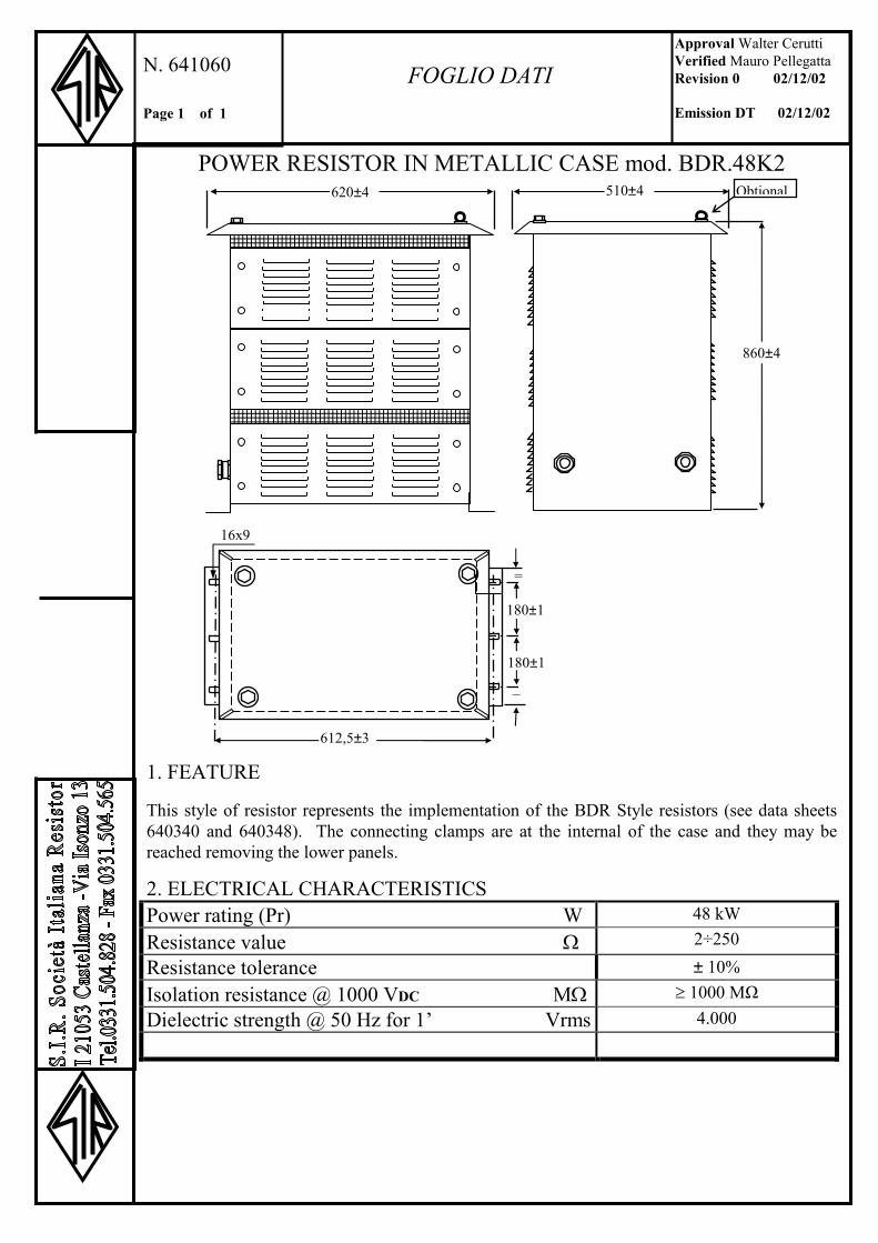
POWER RESISTOR IN METALLIC CASE mod. BDR.48K2
1. FEATURE This style of resistor represents the implementation of the BDR Style resistors (see data sheets 640340 and 640348). The connecting clamps are at the internal of the case and they may be reached removing the lower panels.
2. ELECTRICAL CHARACTERISTICS Power rating (Pr) W 48 kW
Resistance value Ω 2÷250
Resistance tolerance ± 10% Isolation resistance @ 1000 VDC MΩ ≥ 1000 MΩDielectric strength @ 50 Hz for 1’ Vrms 4.000
Approval Walter Cerutti Verified Mauro Pellegatta Revision 0 02/12/02 Emission DT 02/12/02
N. 641060 Page 1 of 1
FOGLIO DATI
510±4 Obtional620±4
860±4
=
=
180±1
180±1
16x9
612,5±3