Embed Size (px)
Citation preview

Application Programming Interface for
Real-Time Receding Horizon Control
Tamas Keviczky∗ and Gary J. Balas†
University of Minnesota, Minneapolis, Minnesota 55455
Andrew Packard‡
University of California, Berkeley, California 94720
Oreste R. Natale§
Universita degli Studi del Sannio, Benevento, Italy 82100
An application programming interface (API) was developed to sup-
port implementation of receding horizon control (RHC) schemes within
the Open Control Platform (OCP) real-time software environment. The
basic philosophy and process timing architecture is presented, along with
details of a prototype implementation of a quadratic programming based
generic RHC scheme. The API framework relies on a real-time software in-
frastructure and provides a high-level interface to control engineers, which
simplifies the embedded control design and implementation process signif-
icantly. The RHC API was successfully flight tested on a full-scale aircraft
in the DARPA-sponsored Software Enabled Control program final demon-
stration experiment.
∗Graduate Research Assistant, Control Science and Dynamical Systems Center, [email protected].†Professor, Department of Aerospace Engineering and Mechanics, [email protected], Associate Fellow
AIAA.‡Professor, Department of Mechanical Engineering, [email protected]., Member AIAA§Post-Doc, Dipartimento di Ingegneria, [email protected].
1 of 21
Application Programming Interface for Real-Time RHC, Keviczky et al

I. Introduction
Control theory and engineering have a remarkably successful history of enabling au-
tomation, and information-centric control is by now pervasive. Yet today’s controllers
are conservative: being products of over-design, they often yield under-performance. Their
designs are statically optimized for nominal performance, around simplified time-invariant
models of systems dynamics and a well-defined operational environment. They also fail in
unexpected circumstances: control vulnerabilities that arise in extreme environments are
frequently ignored. Systems modifications (reconfigurations, damage, failure) may demand
large changes in the controller, perhaps on-line during operation.
With the advent of networked sensors and actuators, distributed computing algorithms,
and hybrid control, the term “systems dynamics” has taken on a whole new meaning.
Whereas it used to bring to mind only ordinary differential equations with perhaps some
parameter uncertainty, noise, or disturbances, we can now include dynamic tasking, sensor
and actuator reconfiguration, fault detection and isolation, and structural changes in plant
model and dimensionality. Consequently, the ideas of system identification, estimation, and
adaptation must be reconsidered.
This new perspective of the world also requires new models for control software imple-
mentation, avoiding treating software as simply the language of implementation. Control
code (particularly, embedded control code) is a dynamic system. It has an internal state,
responds to inputs, and produces outputs. It has time scales, transients, and saturation
points. It can also be adaptive and distributed. As a control engineer knows, if we take
this software dynamic system and couple it to the plant dynamics through the sensor and
actuator dynamics, we have a composite system whose properties cannot be decided from
the subsystems in isolation.
Thus, when we put an embedded controller on a hardware platform, we have not only a
coupled system with significant off-diagonal terms, but a distributed one as well. To borrow
from the computer engineering terminology, we have a problem in control/software co-design.
The control design is evolving through the development of hybrid optimal control, reachabil-
ity analysis, multiple-model systems, and parameter-varying control. The software is being
facilitated by distributed computing and messaging services, distributed object models, real-
time operating systems, and fault detection algorithms.
The growing complexity of control applications requires a software infrastructure that
2 of 21
Application Programming Interface for Real-Time RHC, Keviczky et al

supports the developer in leveraging from inter-process communication, operating systems,
the implementation details of tasks scheduling, and low level device control software in
a seamless manner.1 This enables the developer to concentrate all his design efforts on
the overall system behavior. One of the ultimate goals of the DARPA Software Enabled
Control program2 was the development of the Open Control Platform (OCP), which is a
software technology supporting real-time distributed control application development and
implementation.3 The Receding Horizon Control Application Programming Interface (RHC
API) is a key module within the OCP that was developed to simplify implementation of
receding horizon control schemes for control engineers in a real-time software environment.
The paper is structured as follows. Section II gives a general overview of the Open
Control Platform, which encompasses the RHC API implementation. Details of the RHC
API framework are described in Section III. A brief summary of the DARPA SEC flight test
experiment and simulation results are presented in Section IV.
II. Open control platform overview
The Open Control Platform (OCP) provides an open, middleware-enabled software frame-
work and development platform for control engineers and researchers to aid technology
demonstration in simulated or actual embedded system platforms.4 The middleware layer
of the OCP provides the software layer isolating the application from the underlying target
platform. It provides services for controlling the execution and scheduling of components,
inter-component communication, and distribution and deployment of application compo-
nents onto a target system. The embedded system domain of particular interest to the SEC
program was that of uninhabited aerial vehicles (UAVs), however the software architecture
of the OCP leaves the possibility of applications in other domains open.
The main features of the OCP are the following:
• Provides an open platform for enabling control research and technology transition.
• Supports dynamic configuration of components and services.
• Provides a mechanism enabling the transition between execution and fault management
modes while maintaining control of the target systems.
• Allows for coordinated control of multiple target systems.
3 of 21
Application Programming Interface for Real-Time RHC, Keviczky et al

• Provides a software system infrastructure that is isolated from a particular hardware
platform or operating system.
The major components of the OCP software are summarized in the list below.
• A middleware framework based on RT-CORBA.5 Provides the mechanism for connect-
ing application components together to control their execution.
• A simulation environment. Allows the embedded application to execute and be tested
in a virtual world, reading simulated sensors and driving simulated actuators on plant
models.
• Tool integration support. Provides linkages to useful design and analysis tools such as
Matlab/Simulink and Ptolemy II, allowing controller designs realized in these tools for
easier transition to embedded targets.
• Controls API (Application Programming Interface). Provides a controls-domain friendly
look and feel to the OCP. This is accomplished by using familiar terminology and sim-
plified programming interfaces.
A primary motivating factor in implementing a middleware-based architecture is the promise
of isolating the application components from the underlying platforms. This allows for a more
cost-effective path for implementing common software components that could be used across
different product lines and could be re-hosted onto evolving embedded computing platforms.
The OCP middleware is written in C++. It includes an RT CORBA component,5 which
leverages the ACE and TAO products developed by the distributed object computing (DOC)
research team at Washington University. TAO provides real-time performance extensions to
CORBA.
The OCP classifies hard real-time tasks into different rate groups that have to be prede-
fined by the user and must be factors of the fastest rate. The OCP Frame Controller provides
a synchronous executive that starts all rate processing. The fastest rate is started once each
“minor frame” and slower rates are triggered at appropriate multiples of the minor frame.
For the specific example of the DARPA SEC flight demonstration, minor frames were spec-
ified to execute at a rate of 20 Hz and a major frame of 2 Hz execution rate was defined to
comprise ten minor frames. These major frames will be referred to as computational cycles
in Section B, which describes the timing architecture of the RHC API implementation for
4 of 21
Application Programming Interface for Real-Time RHC, Keviczky et al

the DARPA SEC testbed. The most important services and components of the OCP are
described briefly in the following sections.
A. Middleware services
The OCP provides a set of services in addition to the standard services provided by the
CORBA specification, which gives additional real-time performance enhancements as well
as higher level services (e.g. event service and replication utilities). This forms the application
interface to the underlying middleware and serves two purposes:
• It provides an interface that isolates the application from the details of the underlying
RT CORBA implementation and simplifies the application interface to the lower level
services.
• It provides a clean interface for extending the base features provided by the controls
API.
The OCP’s resource management component provides mechanism for controlling resource
in a mode-specific way. This is an essential element for supporting modes in hybrid systems.
The designer specifies quality of service (QoS) information, which is an input into the resource
management component to control the run-time execution of the OCP. The OCP resource
management component is an extension of the Honeywell Labs real-time adaptive resource
management (RT-ARM) capability.6 This component is responsible for partitioning the
system resources based on the mode of execution. It performs a sort of meta-scheduling
task for the OCP with the assistance of the TAO’s scheduling component.7,8 The resource
management component adjusts rates of execution based on utilization information from the
scheduling component and notifies application components when rates have been adapted.
These components, that are scheduled with the adapted rates, can then modify their behavior
based on the assigned rate (e.g. they can adjust controller gains).
B. Controls API
As described in the previous sections, the OCP provides several advanced mechanisms such as
dynamic scheduling and resource management. To help hide the complexity from the controls
designer, the OCP includes a control designer abstraction layer above the RT CORBA
implementation. This API allows the designer to focus on familiar tools and terminology
5 of 21
Application Programming Interface for Real-Time RHC, Keviczky et al

while enabling the use of RT CORBA extensions. This help provides a consistent view of
the system that is meaningful to the control designer. In order to accomplish this task, the
Controls API has been generalized as a combination of a high level description language and
a simple programming interface. The designer expresses the characteristics of the system
in familiar terms to form a high level description of the system. This description is then
processed to populate a component registry which is used by the OCP.
C. A new concept in real-time control: the anytime task
Most control systems built today are resource-limited. This is especially true for embedded
control systems in mobile platforms due to constraints of size, weight, space or power. Great
effort is expended in engineering solutions that provide jitter-free periodic execution while
meeting hard real-time deadlines in systems with high CPU utilization.
Mission-critical command and control is a resource-constrained yet multifunctional en-
terprise, requiring simultaneous consideration of a variety of activities such as closed-loop
control, measurement and estimation, planning, communication, and fault management. On
the same computational platform, a large number of tasks must execute.
Anytime or incremental algorithms are particularly well suited for implementing tasks
that must adapt their resource usage and quality of service.9,10 In an anytime algorithm,
the quality of the result produced degrades gracefully as the computation time is reduced.
In particular, such algorithms may be interrupted anytime and will always have a valid
result available. If more computation time is provided, the quality of the result will improve.
Examples of applications that could benefit from dynamic resource management range from
automatic target recognition systems to integrated vehicle health monitoring software and
real-time trajectory optimizers that can dynamically replan routes and trajectories of a fleet
of UAVs.
At a given instant, the set of currently executing models and tasks have to adapt to both
internal and external triggers to make optimal use of the available computational resources.
Adaptation among the executing control tasks occurs according to the following steps.
Based on the computed or observed state, the criticality, completion deadlines, and com-
puting requirements for the control tasks are determined. These values may be statically
determined based on the mission mode or computed on-line by a higher-level planning sys-
tem.
The task scheduler makes CPU computing resources available to tasks based on their
6 of 21
Application Programming Interface for Real-Time RHC, Keviczky et al

criticality, computing requirements, and a schedulability analysis. Resources are measured
in terms of CPU utilization and computed as execution rate × execution time per period.
Control tasks execute within their allotted time and are subject to preemption if they
attempt to consume more than their allowed resources. Tasks adapt to meet application
constraints. The anytime scheduler provides tasks with the information necessary to adapt
their computation to the resource available. The application tasks may need to balance the
competing demands of deadlines and accuracy, given the resource made available to them.
In principle, anytime algorithms can make effective use of any amount of processing time
that is available.
Service requirements for the anytime tasks are specified by an application-level policy
task called the Anytime CPU Assignment Controller (ACAC). The ACAC is responsible for
assigning a weight to each anytime task that indicates its relative CPU assignment. This can
be based on deadlines, mission scenario, or other factors. Selection of the appropriate weight
is essentially a control activity that can be used to optimize overall performance. Anytime
tasks are modeled based on the following characteristics:
1. They are continually executing iterative algorithms that are not periodic. Examples
include algorithms that continually refine their result (imprecise computation) and that
produce new outputs based on new inputs.
2. Computation times and deadlines for each iteration of the algorithm are an order of
magnitude larger than the basic periodic rate.
3. The computation time for each iteration is variable and data-dependent. Furthermore,
it is possible for the algorithm to adapt its computation time based on the resource
allocated.
It is important that anytime algorithms coexist with the periodic tasks in the control
system. In order to achieve this coexistence, the anytime task scheduler executes as a
periodic task within the overall control system. This periodic task is assumed to run at the
system clock rate and can be modeled as a periodic task for rate monotonic analysis. The
scheduler allocates a fixed fraction of the overall CPU time for the use of the anytime tasks,
and this allocation is then subdivided based on the allocation of individual anytime tasks.
For other OCP features and services, such as detailed information about resource opti-
mization and anytime task scheduling, the reader is referred to Ref. 3, 11.
7 of 21
Application Programming Interface for Real-Time RHC, Keviczky et al

III. The RHC API
Receding horizon control (RHC) relies on the concept of solving optimal control problems
repetitively for a finite future time horizon based on current measurements. The feedback
nature of this approach emerges from the policy that only the first value of the control so-
lution is implemented at a given instance, and a new optimization problem is solved over
a shifted horizon based on actual measurements at the next time step. The underlying
mathematical programming problem involved in the optimization depends on the choice of
the performance index, the prediction model and constraints. For certain problem classes,
the optimal RHC controller can be calculated explicitly in a piecewise affine state-feedback
form12 without the need for online optimization. However in general, the objective func-
tion and constraints might be nonlinear or the complexity of the equivalent gain-scheduled
controller might warrant the use of an online optimization solver. If computational require-
ments necessitate and the software infrastructure enables such task to be incorporated in the
real-time digital control system, online optimization based techniques offer a very powerful
way to deal with constraints and changes in the controlled system. On the other hand, using
these methodologies it becomes much more challenging to design the control system to meet
real-time computational requirements.
In practice, control engineers invest significant effort in coding the implementation of their
RHC algorithm on a particular hardware platform. This process involves addressing software
engineering issues related to real-time execution requirements and process scheduling. The
main purpose of the RHC API is to provide a high level software interface that builds upon
the services of the OCP to simplify implementation of receding horizon control schemes in
a real-time embedded environment. The objective is to relieve the control designer from the
task of simultaneous algorithm development and real-time software implementation. Relying
on the RHC API framework enables the user to focus most of his efforts on control related
aspects of the application problem and worry less about implementation details.
The fundamental concept of the RHC API is to create an interface at the level of mathe-
matical programs that are involved in all online optimization based receding horizon schemes.
The user is responsible for formulating the receding horizon problem at hand as a mathemati-
cal program of specific characteristics, and the RHC API provides the link to the appropriate
optimization solver and real-time scheduler, which could be thought of as a plug-in module of
the software. A different RHC formulation may result in a different mathematical program.
8 of 21
Application Programming Interface for Real-Time RHC, Keviczky et al

However, as long as a particular formulation belongs to a certain problem class, it is the role
of the RHC API to automate the code generation below the mathematical program level
and interface with the required solver to perform the optimization. Besides providing this
natural interface at the problem formulation level, the API makes use of OCP services which
support implementing the receding horizon scheme in real-time, according to the philosophy
that will be described in Section B.
The prototype RHC API is implemented under the OCP environment (Controls API)
and uses its own problem formulation (more specific abstraction layer than a general math-
ematical program). It relies on LSSOL to solve the Quadratic Program (QP) that results
from the problem formulation module, which takes generic RHC problem parameter inputs
from the user. This specific RHC API implementation is described in the following section.
A. Generic RHC problem formulation
The RHC API version implemented as part of the DARPA SEC flight test experiment
formulates and solves a quadratic optimization problem during each time frame. In this
particular implementation, the interface to the user is provided at a higher abstraction layer,
in the form of a generic RHC problem formulation.13 Formulating the mathematical program
(QP) and invoking the optimization solver is performed automatically. The standard generic
RHC problem formulation considers the following minimization problem
minv
H−1∑
k=0
xTk Qxk + uT
k Ruk +
+ [Cxk − Gdk]T
M [Cxk − Gdk] +
+ vT Fv + KT v + xTHΦxH
(1)
subject to
9 of 21
Application Programming Interface for Real-Time RHC, Keviczky et al

ax,box ≤ xk ≤ bx,box k = 1, . . . , H (2a)
ax ≤ Lxxk ≤ bx k = 1, . . . , H (2b)
au,box ≤ uk ≤ bu,box k = 0, . . . , H − 1 (2c)
au ≤ Luuk ≤ bu k = 0, . . . , H − 1 (2d)
aGu≤ LGu
x1:H
u0:H−1
≤ bGu(2e)
aGv≤ LGv
x1:H
v
≤ bGv(2f)
Here, the linear dynamics of the system are specified by the matrices A, B, and E such that
xk+1 = Axk + Bux + Edk for k = 0, . . . , H − 1 (3)
where the signal d represents both estimated disturbance and desired trajectories. The
control input u sequence is determined from the optimization variables v according to
u0:H−1 :=
u0
...
uH−1
= Uv (4)
The columns of U form a basis for the control input subspace. As a result, the control input
signal can then be written as linear combinations of the columns of U .
Constraints (2a)-(2d) are targeted towards typical operational constraints. The last two
constraint types (2e)-(2f) allow the user to specify general linear constraints involving states,
inputs and optimization variables. The formulation allows the matrices involved in the
problem to be parameter-dependent. These matrices are evaluated each time the problem
formulation is called based on a parameter vector δ.
The problem formulation subroutine maps the system model and cost function matrices
into the variables which parameterize the quadratic program, namely(
Q, L, Z, a, W , b)
. The
10 of 21
Application Programming Interface for Real-Time RHC, Keviczky et al

resulting problem can then be represented as a quadratic program of the form
minv
1
2vT Qv + vT L + Z (5a)
subject to a ≤ Wv ≤ b (5b)
Once formulated, the parameters(
Q, L, Z, a, W , b)
are passed to the quadratic program
solver, LSSOL.
The method of LSSOL14 is a two-phase (primal) quadratic programming method. The
two phases of the method are: finding an initial feasible point by minimizing the sum of
infeasibilities (the feasibility phase), and minimizing the quadratic objective function within
the feasible region (the optimality phase). The computations in both phases are performed
by the same subroutines. The two-phase nature of the algorithm is reflected by changing the
function being minimized from the sum of infeasibilities to the quadratic objective function.
Once any iterate is feasible, all subsequent iterates remain feasible.
LSSOL has been designed to be efficient when used to solve a sequence of related prob-
lems. From this aspect, it is well suited for solving receding horizon control problems or
to be applied in a sequential quadratic programming method for nonlinearly constrained
optimization (e.g. in the NPSOL package15).
If the constrained problem is infeasible, LSSOL returns a flag and the RHC API uses a
subroutine to automatically reformulate a relaxed problem with additional slack variables.
Constraint softening is done using user-specified weights which define the relative “cost” of
relaxing individual constraints.
A nonnegative index vector is defined for each of the lower and upper constraint bound
vectors. Elements that are 0 correspond to constraints that are not relaxed in the reformu-
lation. Positive entries indicate which constraints are relaxed in the reformulation, and their
values represent indices to the associated slack variables (several constraints may be relaxed
with the same slack variable). For instance, consider the lower linear state constraint bound
ax and let aSx,idx be the corresponding nonnegative integer index vector of same dimension.
The i-th element of this vector is associated with the i-th row of the constraints and modifies
it according to
−εaSx,idx(i) + (ax)i ≤ (Lxxk)i k = 1, . . . , H
where εaSx,idx(i) is a constraint relaxation slack variable. Let ε denote the entire slack variable
vector and let ρ be a specified weight vector of same dimension with positive entries. If the
11 of 21
Application Programming Interface for Real-Time RHC, Keviczky et al

original problem is infeasible, the relaxed problem will be formulated as
minv,ε
1
2vT Qv + vT L + Z + ρT ε (6)
subject to the relaxed constraints.
Alternate instances of the generic problem formulation relying on different matrices are
referred to as modes. Each set of data associated with a specific problem formulation has a
corresponding mode number. These numbers are collected in a mode vector I that indicates
which mode the entire system is in at the moment.
The RHC API requires the user to specify the following data before the software compo-
nent can be built:
• dimensions (input, state, constraint, parameter vector, mode vector, horizon length)
• dynamics (in the form of mode and parameter-dependent matrices)
• cost function (in the form of mode and parameter-dependent matrices)
• constraints (in the form of mode and parameter-dependent matrices)
• weights for constraint relaxation
• basis set for input
• warm-start function (described in Section B)
In general, an iterative process is required to solve a quadratic program. The following
section describes the RHC API timing architecture and the term “iteration” will be used to
refer to the number of iterations in the optimality phase and the feasibility phase together
using LSSOL as the optimization solver.
B. Conceptual timing architecture
The RHC API is implemented as three different tasks within the OCP environment. These
tasks are referred to as Pre, Opt and Post. Their execution spans a single major frame of
the scheduler, which runs at 2 Hz for the specific application example of the DARPA SEC
flight test. The minor frame rate was specified to be 20 Hz.
12 of 21
Application Programming Interface for Real-Time RHC, Keviczky et al

These three tasks implement different parts of the receding horizon control scheme based
on user supplied data. The RHC API formulates, solves and computes the proper control
action to be taken according to the following policy.
At time step k, the RHC API component receives the following data (exogenous inputs)
from other OCP components:
• state estimate, xest(k)
• signal estimate, dest(k : k + H − 1)
• mode vector, I
• parameter vector, δ
The hard real-time task Pre runs at the beginning of each major frame and is responsible
for executing two primary operations. It calls the user-supplied warm-start function and
formulates the RHC problem based on current measurements and user supplied data. The
linearly constrained, quadratic program is constructed using the state and signal estimates,
the reference signal, and the dynamics, constraint and cost matrices according to current
values of I and δ.
The user-supplied warm-start function has to perform two calculations. First, initialize
the decision variable v, based on current inputs and data from the previous frame. It also
computes a candidate baseline control action u0 using any method that has a guaranteed
completion time.
Although problem-dependent, the user is expected to provide worst-case execution times
for both of these steps, so they can be scheduled in hard real-time fashion.
The problem formulation is then passed to the anytime task Opt, which is enabled to run
after Pre is finished. It is important to note that Pre is designed to have a small worst-case
execution time. Opt solves the constrained optimization problem by calling the appropriate
mathematical program solver. If the problem is infeasible, a relaxed version is solved after
reformulation according to (6).
One minor frame before the next 2 Hz major frame, i.e. 450 ms after the start of the
current major frame, Opt is terminated by the scheduler and Post is called. Post is a
hard real-time task, which processes the most recent (either intermediate or final) optimal
iterate v∗ of the solver. The corresponding control action u∗ is calculated and a decision
is made whether to use the baseline control action u0 or u∗. The baseline solution can be
13 of 21
Application Programming Interface for Real-Time RHC, Keviczky et al

OPT
PRE tPOST
PRE PREOPT POST
450 ms 500 ms0 ms
t
t
Figure 1. Scheduling of the Pre, Opt and Post tasks within the RHC API.
considered for implementation in case the solver could not complete a single iteration, or
the intermediate solution quality is not acceptable due to infeasibility or high cost. Finally,
Post outputs the desired control action at the end of the major frame.
The timing of the three basic tasks of the RHC API is depicted in Figure 1. Descriptions
of the Pre, Opt and Post tasks are summarized in Table 1.
The main motivation behind this scheduling scheme is to allow a variable amount of
computational time for the most computationally intensive calculations. The online opti-
mization is performed iteration by iteration in an “anytime” fashion, so it can make use of
more computational time if made available by the scheduler.
Figure 2 illustrates the signal-flow relationship between the three RHC API tasks and
the user libraries. The user libraries include RHC problem formulation data (parameters,
prediction models and any other user-defined input data) as a collection of possible modes.
The libraries should also provide the user-defined functionalities within the Pre and Post
processes, such as the warm-start function and the control solution calculation.
Task Name Task Type Description
Pre Hard Real-TimeRHC problem formulation, candi-date control action.
Opt AnytimeSolves constrained optimizationproblem, relaxation if necessary.
Post Hard Real-TimeRHC problem solution process-ing, desired control action.
Table 1. Description of RHC API tasks.
14 of 21
Application Programming Interface for Real-Time RHC, Keviczky et al

solution
User library
NPSOL SNOPT
NLP
. . . LSSOL
QP
. . .
OPT
δ
I
v * u *
: control outputu
v : optimization variables
: mode
: parameters
I
δ
v initial
I I
δ δ
POST
Generate
outputδ
I
PRE
Baseline
Figure 2. Conceptual signal-flow architecture of the Pre, Opt and Post tasks within the RHCAPI.
C. Implementation details
The RHC API implementation for the DARPA SEC flight experiment was designed with
the specific needs of this application example in mind.
The quadratic program solver LSSOL has been modified in order to allow recovery of
intermediate iterates following premature termination from other processes. Section 10 of
the LSSOL license from SBSI allows for modifications to the software. The RHC guidance
algorithm and underlying LSSOL solver, the RHC API, and the OCP middleware were all
implemented and housed on a laptop computer running the QNX real-time operating system.
User-specified code segments were implemented using an object oriented software engi-
neering approach to flight code design.16 Extra care had to be taken to make sure that the
user-specified code contains no dynamic memory allocations, which is a strict requirement
in real-time software applications. Within the RHC API, the optimization solver LSSOL
allows allocating larger memory space for its input parameters than their actual size. This
is very useful if the relaxed version of the optimization problem has to be formulated due to
infeasibility, since it is possible to allocate the worst-case memory workspace at startup and
avoid the need for any dynamic memory allocation.
The RHC API requires a baseline control solution to be calculated within Pre for imple-
mentation if the optimization is found to be infeasible or result in a poor quality solution. In
15 of 21
Application Programming Interface for Real-Time RHC, Keviczky et al

the actual flight code for the DARPA SEC experiment, the baseline solution was to maintain
the current speed, heading and altitude measurement values, which was always feasible to
implement using an autopilot as described in the following section.
IV. DARPA SEC fixed wing demonstration experiment
Several universities and aerospace companies were involved in the two-week long final
flight demonstrations of the DARPA Software Enabled Control project, each having their
own experimental flight scenario to be tested. The main objective of the University of
Minnesota / University of California Berkeley team was to demonstrate in a flight experiment
the use of advanced receding horizon guidance technologies, which are enabled by the real-
time software tools of the RHC API and the OCP middleware.
The testbed was a full-scale T-33 jet aircraft outfitted with an autopilot and the avion-
ics package of the X-45 UCAV unmanned aircraft. The control objective was to perform
autonomous guidance and track a time-stamped reference trajectory in space while respect-
ing the aircraft’s maneuvering limits and in the presence of simulated actuator faults. The
control inputs of ground speed, turn rate and altitude were fed into the autopilot, which
performed the lower level control of the aircraft. The autopilot was flight certified and safe
to operate, which reduced the verification requirements on the online optimization based
control law.
A brief description of the flight demonstration experiment scenario is provided next. The
timeline of events starts with engaging the RHC controller in a pre-specified area near the
ingress point once the starting conditions are met. The controller tracks a time-stamped
position reference trajectory while respecting constraints on the vehicle dynamics. At a
certain point along the reference trajectory, a pop-up threat can be invoked by a ground
operator, which results in a switch to an alternative reference trajectory that avoids the
threat. After the target is reached with a specified heading, a simulated fault was inserted
into the system, which was detected shortly thereafter at a trajectory segment designed
specifically for this purpose. After detection, the fault was removed and the aircraft returned
to the egress point. These events resulted eventually in a reference trajectory that will be
shown in all subsequent plots illustrating simulation or flight test results.
In a second, more ambitious scenario, the fault is not removed from the system after
detection, and the RHC controller is reconfigured to adapt to the faulty vehicle dynamics.
16 of 21
Application Programming Interface for Real-Time RHC, Keviczky et al

Constraints are also adjusted to restrict the aircraft’s maneuvers.
Description of the fault detection filter design and test results are omitted in this paper
and can be found in Ref. 11,17, along with simulations that show successful reconfiguration
of the RHC controller after a fault. Flight test results of the RHC controller are also reported
in Ref. 18.
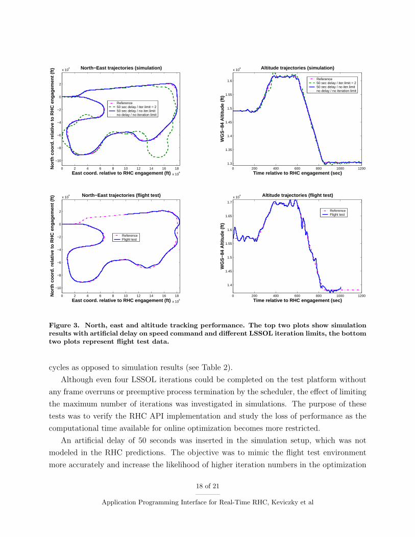
A. Simulation and flight test results
The receding horizon guidance controller was tested in simulation with different wind con-
ditions and showed excellent robustness. With the exception of a few time samples, the
optimization converged within two iterations throughout the entire simulation, without be-
ing terminated by the scheduler. The top two plots in Figure 3 show simulated tracking
performance in the north-east coordinate frame and in terms of altitude indicating excellent
tracking performance. The reference trajectory resulted from no-fly-zone and pop-up threat
avoidance, reaching a stationary target and performing fault detection experiments.
The bottom two plots in Figure 3 illustrate results from the flight test, which took place
at Edwards Air Force Base in the Mojave desert in June 2004. The main reason for deviations
from the reference trajectory and degraded tracking performance during flight test was that
automatic speed control was not available on the test platform. Tracking a time-stamped
position reference trajectory requires tight control of the aircraft’s velocity. However, during
the flight test airspeed was controlled using manual adjustments to the throttle by the pilot,
who was cued by a three-state LED indicator whether to increase, decrease or maintain the
velocity of the aircraft based on commanded and measured ground speed. The dead-zone of
the “maintain speed” status indicator was approximately 30 ft/s. Another factor influencing
the outcome of experiments was that flight tests were conducted in the presence of strong
winds (25-30 knots).
Post-flight data analysis showed an average delay of 50-100 seconds in the velocity com-
mand channel, which was not modeled in the RHC controller. The implemented RHC
controller was tested only up to 10-20 samples (5-10 seconds) of unmodeled additional delay
compared to the prediction model and showed acceptable degradation of performance.
Due to the extra delay in the speed command channel and the resulting model mismatch,
constraints became active more frequently during the flight test. This increased the compu-
tational time required by the online optimization solver. LSSOL converged to a solution in
three or four iterations during a significant percentage of the total number of computational
17 of 21
Application Programming Interface for Real-Time RHC, Keviczky et al
0 2 4 6 8 10 12 14 16 18
x 104
−10
−8
−6
−4
−2
0
2
x 104
East coord. relative to RHC engagement (ft)
Nor
th c
oord
. rel
ativ
e to
RH
C e
ngag
emen
t (ft)
North−East trajectories (flight test)
ReferenceFlight test
0 2 4 6 8 10 12 14 16 18
x 104
−10
−8
−6
−4
−2
0
2
x 104
East coord. relative to RHC engagement (ft)
Nor
th c
oord
. rel
ativ
e to
RH
C e
ngag
emen
t (ft)
North−East trajectories (simulation)
Reference50 sec delay / iter.limit = 250 sec delay / no iter.limitno delay / no iteration limit
0 200 400 600 800 1000 1200
1.4
1.45
1.5
1.55
1.6
1.65
1.7
x 104
Time relative to RHC engagement (sec)
WG
S−8
4 A
ltitu
de (
ft)
Altitude trajectories (flight test)
ReferenceFlight test
0 200 400 600 800 1000 12001.3
1.35
1.4
1.45
1.5
1.55
1.6
x 104
Time relative to RHC engagement (sec)
WG
S−8
4 A
ltitu
de (
ft)
Altitude trajectories (simulation)
Reference50 sec delay / iter.limit = 250 sec delay / no iter.limitno delay / no iteration limit
Figure 3. North, east and altitude tracking performance. The top two plots show simulationresults with artificial delay on speed command and different LSSOL iteration limits, the bottomtwo plots represent flight test data.
cycles as opposed to simulation results (see Table 2).
Although even four LSSOL iterations could be completed on the test platform without
any frame overruns or preemptive process termination by the scheduler, the effect of limiting
the maximum number of iterations was investigated in simulations. The purpose of these
tests was to verify the RHC API implementation and study the loss of performance as the
computational time available for online optimization becomes more restricted.
An artificial delay of 50 seconds was inserted in the simulation setup, which was not
modeled in the RHC predictions. The objective was to mimic the flight test environment
more accurately and increase the likelihood of higher iteration numbers in the optimization
18 of 21
Application Programming Interface for Real-Time RHC, Keviczky et al

Test cases Number of LSSOL iterations
1 2 3 4
Nominal simulation (no delay, no iteration limit) 0.04 % 99.92 % 0.04 % 0.00 %
Flight test 1.10 % 59.63 % 38.92 % 0.35 %
Simulation (50 sec Vcmd delay, no iteration limit) 0.04 % 65.81 % 33.94 % 0.21 %
Simulation (50 sec Vcmd delay, iteration limit = 3) 0.04 % 65.85 % 34.11 % 0.00 %
Simulation (50 sec Vcmd delay, iteration limit = 2) 0.04 % 99.96 % 0.00 % 0.00 %
Table 2. Distribution of computational cycles by required number of LSSOL iterations.
thread. The resulting performance was similar to the one observed during flight tests and is
depicted in the top two plots in Figure 3. Distribution of computational cycles by number
of iterations is reported in Table 2. Since the percentage of major frames requiring four
LSSOL iterations was negligible, the controller performance was essentially unaffected by
limiting the maximum number of iterations to three. However, a limit of two iterations
per cycle resulted in a significant, but not devastating loss of performance as shown in the
top two plots in Figure 3. The performance degradation can be attributed mainly to the
poor quality speed control solution. The large artificial delay in the speed command channel
resulted in velocity oscillations and frequent saturation of flight envelope limits in terms
of true airspeed. Since this led to constraints being active most of the time, the number
of iterations in the feasibility phase of LSSOL increased. Due to the artificially imposed
iteration limit, after a feasible solution was found, it could not be improved upon by further
iterations in the optimization phase. This led to poor quality speed control, which resulted
in the significant lateral oscillations shown in the top left plot of Figure 3. As the aircraft
was trying to match the time-stamped position reference, it veered away to “bleed off” time
when travelling with higher than optimal groundspeed. These results illustrate that the RHC
API was able to handle situations where the available computational time was restricted by
enforcing artificial limits on the allowable number of LSSOL iterations.
19 of 21
Application Programming Interface for Real-Time RHC, Keviczky et al

V. Conclusions
An application programming interface was developed for real-time receding horizon con-
trol applications (RHC API) using the OCP middleware. The API enables simpler RHC
implementation in a real-time embedded software environment and provides a natural inter-
face to the control designer at the mathematical program level. A prototype of the RHC
API was successfully implemented and flight tested in the DARPA Software Enabled Control
program’s final demonstration experiment.
Acknowledgements
This work was funded by the Defense Advanced Research Projects Agency under the
Software Enabled Control program, Dr. John Bay Program Manager. The contract number
is USAF/AFMC F33615-99-C-1497, Dale Van Cleave is the Technical Contract Monitor.
The authors would like to acknowledge Brian Mendel, Tim Espey and Jared Rosson at
the Boeing Company for their help and support with the integration of the RHC API into
the Open Control Platform. The authors would also like to acknowledge Kenneth Hsu, Sean
Estill, Zachary Jarvis-Wloszek and Raktim Bhattacharya for their work on different versions
of the RHC API implementation.
References
1Samad, T. and Balas, G. J., Software-Enabled Control: Information Technology for Dynamical Sys-
tems, Wiley Interscience – IEEE Press, 2003.
2Bay, J. S. and Heck, B. S., “Special Section: Software-Enabled Control,” IEEE Control Systems
Magazine, Vol. 23, No. 1, Feb. 2003.
3Paunicka, J., Mendel, B., and Corman, D., “The OCP – An open middleware solution for embedded
systems,” Proc. of the American Control Conf., Arlington, VA, 2001, pp. 3345–3350.
4Paunicka, J. L., Mendel, B. R., and Corman, D. E., Software-Enabled Control , chap. Open Control
Platform: a software platform supporting advances in UAV control technology, Wiley Interscience – IEEE
Press, 2003, pp. 38–62.
5Object Management Group, “Realtime CORBA joint revised submission,” Tech. Rep. 99-02-12, OMG
Document orbos, March 1999.
6Rosu, D., Schwan, K., Yalmanchili, S., and Jha, R., “On adaptive resource allocation for complex
real-time applications,” Proc. IEEE Real-Time Systems Symposium, Dec. 1997.
20 of 21
Application Programming Interface for Real-Time RHC, Keviczky et al

7Doerr, B. S., Venturella, T., Jha, R., Gill, C. D., and Schmidt, D. C., “Adaptive Scheduling for Real-
Time, Embedded Information Systems,” Proc. 18th IEEE / AIAA Digital Avionics Systems Conference,
Oct. 1999.
8Gill, C. D., Schmidt, D. C., and Cytron, R., “Multi-paradigm scheduling for distributed real-time
embedded computing,” IEEE Proceedings Special Issue on Embedded Systems, 2002.
9Agrawal, M., Cofer, D., and Samad, T., Software-Enabled Control , chap. Real-Time adaptive resource
management for multimodel control, Wiley Interscience – IEEE Press, 2003, pp. 85–103.
10Agrawal, M., Coffer, D., and Samad, T., “Real-Time Adaptive Resource Management for Advanced
Avionics,” IEEE Control Systems Magazine, Vol. 23, No. 1, Feb. 2003, pp. 76–88.
11Keviczky, T., Ingvalson, R., Rotstein, H., Packard, A., Natale, O. R., and Balas, G. J., “An Integrated
Multi-Layer Approach to Software Enabled Control: Mission Planning to Vehicle Control,” Tech. rep.,
Department of Aerospace Engineering and Mechanics. University of Minnesota, Minneapolis. Department of
Mechanical Engineering University of California, Berkeley, Nov. 2004.
12Borrelli, F., Constrained Optimal Control of Linear and Hybrid Systems, Vol. 290 of Lecture Notes in
Control and Information Sciences, Springer, 2003.
13Estill, S. M., “Real-time Receding Horizon Control: Application Programmer Interface Employing
LSSOL,” Tech. rep., Department of Mechanical Engineering, University of California, Berkeley, Dec. 2003.
14Gill, P. E., Hammarling, S. J., Murray, W., Saunders, M. A., and Wright, M. H., User’s Guide
for LSSOL (Version 1.0): a FORTRAN package for constrained linear least-squares and convex quadratic
programming , Systems Optimization Laboratory, Department of Operations Research, Stanford University,
1986.
15Gill, P. E., Murray, W., Saunders, M. A., and Wright, M. H., User’s Guide for NPSOL 5.0: a
FORTRAN package for nonlinear programming , University of California, San Diego. Stanford University.
Bell Laboratories., 1998.
16Natale, O. R., Models and Tools for Advanced Real-Time Control Systems, Ph.D. thesis, Department
of Engineering, Universita degli Studi del Sannio in Benevento, Benevento, Italy, 2004.
17Rotstein, H. P., Ingvalson, R., Keviczky, T., and Balas, G. J., “Input-Dependent Threshold Function
for an Actuator Fault Detection Filter,” 16th IFAC World Congress, Prague, Czech Republic, July 2005.
18Keviczky, T. and Balas, G. J., “Flight Test of a Receding Horizon Controller for Autonomous UAV
Guidance,” Proc. of the American Control Conf., Portland, Oregon, June 2005.
21 of 21
Application Programming Interface for Real-Time RHC, Keviczky et al