Embed Size (px)
Citation preview
Advances in Production Engineering & Management 6 (2011) 4, 259-270 ISSN 1854-6250 Scientific paper
259
APPLICATION OF LASER RE-MELTING ON SELECTIVE LASER MELTING PARTS
Yasa, E.* & Kruth, J.*
*Catholic University of Leuven, Dept. of Mech. Eng., Heverlee, Belgium
E-mail: [email protected] Abstract: Selective Laser Melting (SLM) is an additive manufacturing process whereby a three-dimensional part with almost full density and good mechanical properties is built in a layer-wise manner. During the process, a laser source selectively scans a powder bed according to the CAD data of the part to be produced and the powder metal particles are completely melted. In this way, SLM is capable of producing functional metallic parts with a high geometrical freedom. However, there are some limitations to the process including insufficient surface quality, remnant porosity (~1-2%) and stair effect which is inherent to all layer manufacturing processes. In this study, laser re-melting is applied using a continuous wave Nd:YAG laser during SLM of AISI 316L stainless steel parts to overcome or to weaken these limitations. After each layer is fully molten, the same slice data is used to re-expose the layer for laser re-melting. In this manner, laser re-melting does not only improve the surface quality but also has the potential to improve density. The influence of laser re-melting on density enhancement, surface quality and stair-effect is studied varying the operating parameters such as scan speed, laser power and scan spacing. The laser re-melting method with optimized parameter settings greatly densifies the SLM part and improves the surface quality significantly at a cost of longer production times. The stair-effect is also greatly eliminated when laser re-melting is applied on the inclined surfaces after the process is completed and the surrounding powder particles are blown away. Key Words: Selective Laser Melting, Laser Re-melting
1. INTRODUCTION Selective Laser Melting (SLM) is an additive manufacturing technology able to fabricate 3D physical models, parts and tools without almost any geometrical restrictions by stacking and bonding 2D layers in a specified building direction. The process is able to produce almost 100% dense parts directly from design data using customary metal powders. The main advantage of SLM is the ability to produce very complex parts which are almost impossible to be made with conventional production techniques. Bone scaffolds and molds with conformal cooling channels are good examples to explore the unlimited geometrical freedom in this process (Figure 1). Compared to other layer manufacturing technologies, SLM has the advantage to produce parts that have mechanical properties comparable to those of bulk materials [1].
Figure 1: Sample parts produced by SLM.
Yasa & Kruth: Application of Laser Re-Melting on Selective Laser Melting Parts
260
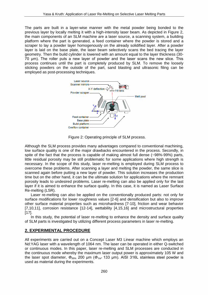
The parts are built in a layer-wise manner with the metal powder being bonded to the previous layer by locally melting it with a high-intensity laser beam. As depicted in Figure 2, the main components of an SLM machine are a laser source, a scanning system, a building platform where the part is generated, a feed container where the powder is stored and a scraper to lay a powder layer homogenously on the already solidified layer. After a powder layer is laid on the base plate, the laser beam selectively scans the bed tracing the layer geometry. Then the build cylinder is lowered with an amount equal to the layer thickness (30-70 µm). The roller puts a new layer of powder and the laser scans the new slice. This process continues until the part is completely produced by SLM. To remove the loosely sticking powders on the outside of the part, sand blasting and ultrasonic filing can be employed as post-processing techniques.
Figure 2: Operating principle of SLM process. Although the SLM process provides many advantages compared to conventional machining, low surface quality is one of the major drawbacks encountered in the process. Secondly, in spite of the fact that the process is capable of making almost full dense (~98%-99%) parts, little residual porosity may be still problematic for some applications where high strength is necessary. In the scope of this study, laser re-melting is employed during SLM process to overcome these problems. After scanning a layer and melting the powder, the same slice is scanned again before putting a new layer of powder. This solution increases the production time but on the other hand, it can be the ultimate solution for applications where the remnant porosity leads to undesired problems. Laser re-melting can also be applied only for the last layer if it is aimed to enhance the surface quality. In this case, it is named as Laser Surface Re-melting (LSR).
Laser re-melting can also be applied on the conventionally produced parts: not only for surface modifications for lower roughness values [2-6] and densification but also to improve other surface material properties such as microhardness [7-10], friction and wear behavior [7,10,11], corrosion resistance [12-14], wettability [4,15,16] and microstructural properties [17].
In this study, the potential of laser re-melting to enhance the density and surface quality of SLM parts is investigated by utilizing different process parameters in laser re-melting.
2. EXPERIMENTAL PROCEDURE All experiments are carried out on a Concept Laser M3 Linear machine which employs an Nd:YAG laser with a wavelength of 1064 nm. The laser can be operated in either Q-switched or continuous modes. In this paper, laser re-melting and SLM processes are conducted in the continuous mode whereby the maximum laser output power is approximately 105 W and the laser spot diameter, Ф99% 200 µm (Ф1/e² 133 µm). AISI 316L stainless steel powder is used as material during the experiments.

Yasa & Kruth: Application of Laser Re-Melting on Selective Laser Melting Parts
261
The parameters used during selective laser melting of the powder are the standard values optimized for maximum density (scan speed 380 mm/s, laser power 105 W and scan spacing 125 µm). After SLM of each layer, the same slice is scanned with a different set of re-melting parameters. While changing some parameters such as scan spacing, scan speed, number of re-melting scans or laser power, some parameters were kept constant throughout the experiments: a spot size of 200 µm as well as a scan strategy of all 0° hatch lines. With a spot size of 200 µm, a pump current of 39 A corresponds to a laser power of 105 W whereas a pump current of 35 A corresponds to 85 W. The scan spacing factor (a1) determines the scan spacing between two consecutive scan lines. As a1 decreases, the scan lines are located closer to each other. In the laser re-melting experiments to enhance the density, the scan speed is changed in the range of 50 to 200 mm/s whereas a scan spacing factor a1 is varied between 5% and 20% of the spot diameter. The effect of the laser power is investigated in the ranges of 85 to 105 W as well as two different numbers of re-melting scans. In order to study the influence of the laser re-melting on the surface quality, only the last layer of the part is exposed to laser re-melting to save some production time. The parameters utilized during LSR are explained in §3.2 Surface Quality Improvement.
3. RESULTS AND DISCUSSION 3.1 Density Improvement The cross-section of a SLM part without any re-melting process observed with an optical microscope is shown in Figure 3. The black spots throughout the part are the pores that are created during the SLM process. They are homogeneously distributed and can be formed due to several reasons such as decrease in the solubility of the dissolved elements in the molten pool during cooling and solidification and evaporation of elements with a high vapour pressure [18]. Besides those melting and solidification phenomena, an insufficient surface quality can cause low density as well: High roughness peaks and valleys that are formed after each layer can avoid the scraper to deposit a uniform powder layer. Moreover, the laser energy may be not enough to melt the new layer completely since the depth of the powder in some regions might be thicker. Morgan et al. has already found that a rough surface causes the entrapment of gas upon deposition of a new powder layer. When the new layer is being scanned, the gas is superheated and expands rapidly removing the liquid metal above it, thus creating a pore [19].
Figure 3: Cross-section of an SLM part with no laser re-melting.
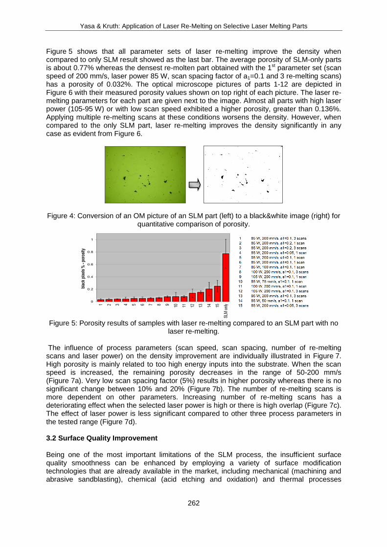
In order to get a quantitative comparison between applying different laser re-melting parameters and parts produced by only SLM without re-melting, the densities of the parts were measured using cross-sectional images obtained with optical microscopy. In order to achieve this, first the pictures are converted to black and white images using a constant threshold value (See Figure 4). Then the ratio of the number of black pixels to the total one, representing the porosity, was calculated for each image. For every set of parameters, at least three pictures taken at different locations of the cross-section are used. The average porosity results measured in this way are given in Figure 5 with a confidence level of 95%.
Yasa & Kruth: Application of Laser Re-Melting on Selective Laser Melting Parts
262
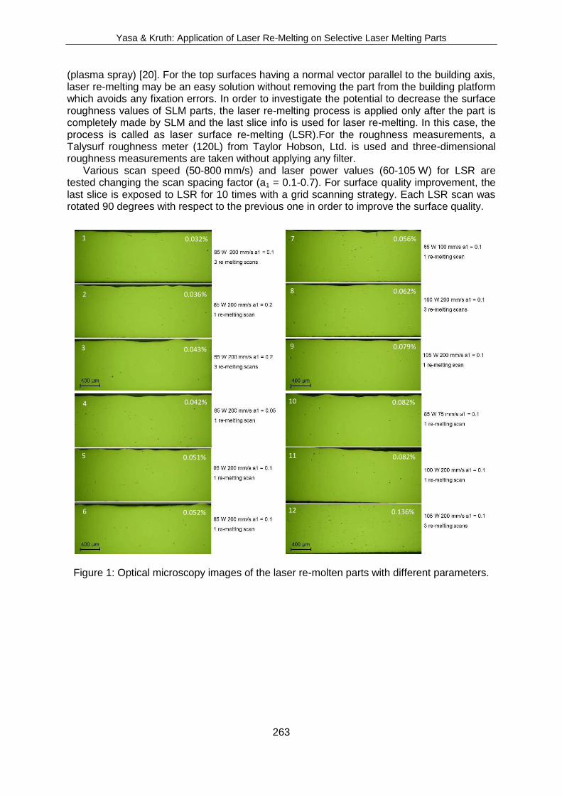
Figure 5 shows that all parameter sets of laser re-melting improve the density when compared to only SLM result showed as the last bar. The average porosity of SLM-only parts is about 0.77% whereas the densest re-molten part obtained with the 1st parameter set (scan speed of 200 mm/s, laser power 85 W, scan spacing factor of a1=0.1 and 3 re-melting scans) has a porosity of 0.032%. The optical microscope pictures of parts 1-12 are depicted in Figure 6 with their measured porosity values shown on top right of each picture. The laser re-melting parameters for each part are given next to the image. Almost all parts with high laser power (105-95 W) or with low scan speed exhibited a higher porosity, greater than 0.136%. Applying multiple re-melting scans at these conditions worsens the density. However, when compared to the only SLM part, laser re-melting improves the density significantly in any case as evident from Figure 6.
Figure 4: Conversion of an OM picture of an SLM part (left) to a black&white image (right) for quantitative comparison of porosity.
Figure 5: Porosity results of samples with laser re-melting compared to an SLM part with no
laser re-melting.
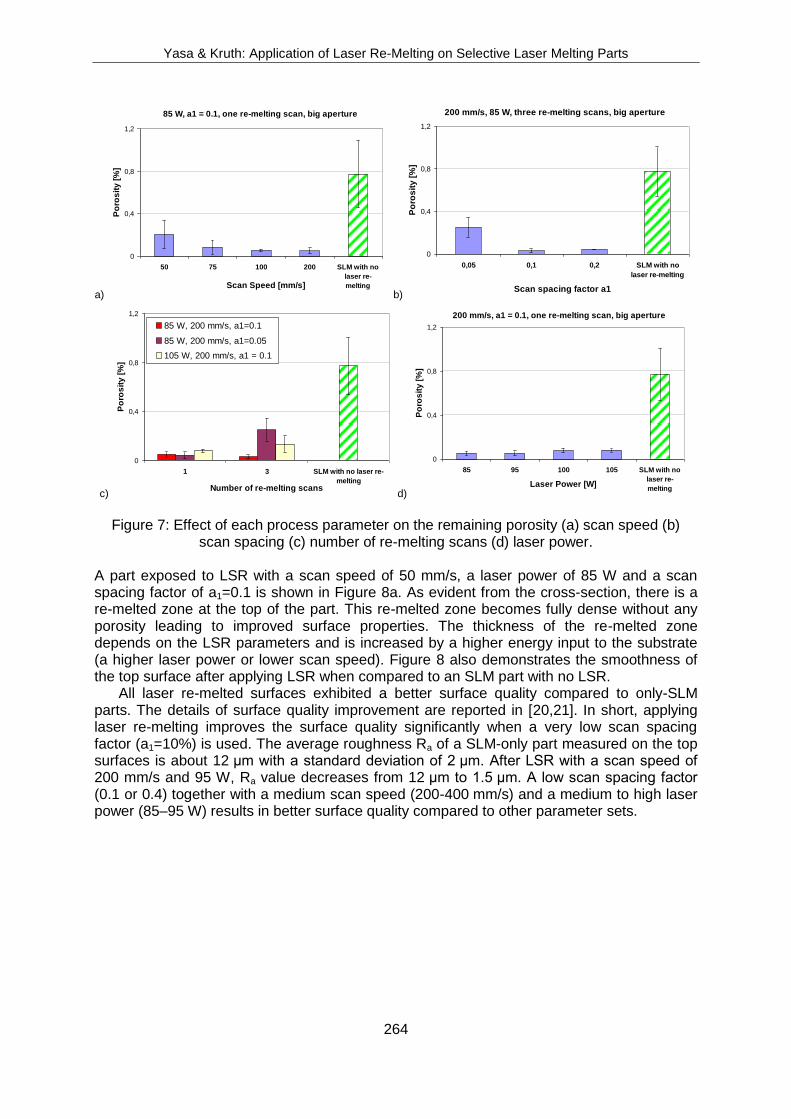
The influence of process parameters (scan speed, scan spacing, number of re-melting scans and laser power) on the density improvement are individually illustrated in Figure 7. High porosity is mainly related to too high energy inputs into the substrate. When the scan speed is increased, the remaining porosity decreases in the range of 50-200 mm/s (Figure 7a). Very low scan spacing factor (5%) results in higher porosity whereas there is no significant change between 10% and 20% (Figure 7b). The number of re-melting scans is more dependent on other parameters. Increasing number of re-melting scans has a deteriorating effect when the selected laser power is high or there is high overlap (Figure 7c). The effect of laser power is less significant compared to other three process parameters in the tested range (Figure 7d). 3.2 Surface Quality Improvement Being one of the most important limitations of the SLM process, the insufficient surface quality smoothness can be enhanced by employing a variety of surface modification technologies that are already available in the market, including mechanical (machining and abrasive sandblasting), chemical (acid etching and oxidation) and thermal processes
Yasa & Kruth: Application of Laser Re-Melting on Selective Laser Melting Parts
263
(plasma spray) [20]. For the top surfaces having a normal vector parallel to the building axis, laser re-melting may be an easy solution without removing the part from the building platform which avoids any fixation errors. In order to investigate the potential to decrease the surface roughness values of SLM parts, the laser re-melting process is applied only after the part is completely made by SLM and the last slice info is used for laser re-melting. In this case, the process is called as laser surface re-melting (LSR).For the roughness measurements, a Talysurf roughness meter (120L) from Taylor Hobson, Ltd. is used and three-dimensional roughness measurements are taken without applying any filter.
Various scan speed (50-800 mm/s) and laser power values (60-105 W) for LSR are tested changing the scan spacing factor (a1 = 0.1-0.7). For surface quality improvement, the last slice is exposed to LSR for 10 times with a grid scanning strategy. Each LSR scan was rotated 90 degrees with respect to the previous one in order to improve the surface quality.
Figure 1: Optical microscopy images of the laser re-molten parts with different parameters.
1
2
3
4
5
6
7
8
9
10
11
12
0.032%
0.036%
0.043%
0.042%
0.051%
0.052%
0.056%
0.062%
0.079%
0.082%
0.082%
0.136%
Yasa & Kruth: Application of Laser Re-Melting on Selective Laser Melting Parts
264
a)
85 W, a1 = 0.1, one re-melting scan, big aperture
0
0,4
0,8
1,2
50 75 100 200 SLM with no
laser re-
meltingScan Speed [mm/s]
Po
ros
ity
[%
]
b)
200 mm/s, 85 W, three re-melting scans, big aperture
0
0,4
0,8
1,2
0,05 0,1 0,2 SLM with no
laser re-melting
Scan spacing factor a1
Po
ros
ity
[%
]
c)
0
0,4
0,8
1,2
1 3 SLM with no laser re-
meltingNumber of re-melting scans
Po
ros
ity
[%
]
85 W, 200 mm/s, a1=0.1
85 W, 200 mm/s, a1=0.05
105 W, 200 mm/s, a1 = 0.1
d)
200 mm/s, a1 = 0.1, one re-melting scan, big aperture
0
0,4
0,8
1,2
85 95 100 105 SLM with no
laser re-
meltingLaser Power [W]
Po
ros
ity
[%
]
Figure 7: Effect of each process parameter on the remaining porosity (a) scan speed (b)
scan spacing (c) number of re-melting scans (d) laser power. A part exposed to LSR with a scan speed of 50 mm/s, a laser power of 85 W and a scan spacing factor of a1=0.1 is shown in Figure 8a. As evident from the cross-section, there is a re-melted zone at the top of the part. This re-melted zone becomes fully dense without any porosity leading to improved surface properties. The thickness of the re-melted zone depends on the LSR parameters and is increased by a higher energy input to the substrate (a higher laser power or lower scan speed). Figure 8 also demonstrates the smoothness of the top surface after applying LSR when compared to an SLM part with no LSR. All laser re-melted surfaces exhibited a better surface quality compared to only-SLM parts. The details of surface quality improvement are reported in [20,21]. In short, applying laser re-melting improves the surface quality significantly when a very low scan spacing factor (a1=10%) is used. The average roughness Ra of a SLM-only part measured on the top surfaces is about 12 µm with a standard deviation of 2 µm. After LSR with a scan speed of 200 mm/s and 95 W, Ra value decreases from 12 µm to 1.5 µm. A low scan spacing factor (0.1 or 0.4) together with a medium scan speed (200-400 mm/s) and a medium to high laser power (85–95 W) results in better surface quality compared to other parameter sets.
Yasa & Kruth: Application of Laser Re-Melting on Selective Laser Melting Parts
265
a) b)
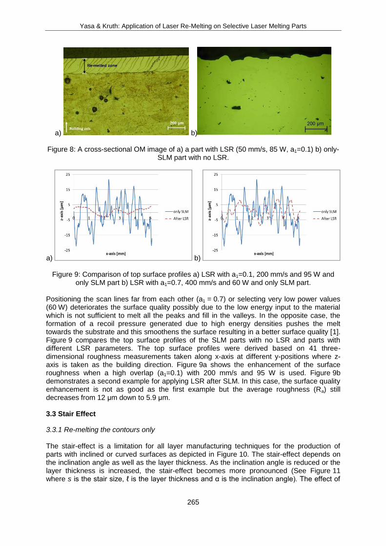
Figure 8: A cross-sectional OM image of a) a part with LSR (50 mm/s, 85 W, a1=0.1) b) only-SLM part with no LSR.
a) b)
Figure 9: Comparison of top surface profiles a) LSR with a1=0.1, 200 mm/s and 95 W and only SLM part b) LSR with a1=0.7, 400 mm/s and 60 W and only SLM part.
Positioning the scan lines far from each other (a1 = 0.7) or selecting very low power values (60 W) deteriorates the surface quality possibly due to the low energy input to the material which is not sufficient to melt all the peaks and fill in the valleys. In the opposite case, the formation of a recoil pressure generated due to high energy densities pushes the melt towards the substrate and this smoothens the surface resulting in a better surface quality [1]. Figure 9 compares the top surface profiles of the SLM parts with no LSR and parts with different LSR parameters. The top surface profiles were derived based on 41 three-dimensional roughness measurements taken along x-axis at different y-positions where z-axis is taken as the building direction. Figure 9a shows the enhancement of the surface roughness when a high overlap (a1=0.1) with 200 mm/s and 95 W is used. Figure 9b demonstrates a second example for applying LSR after SLM. In this case, the surface quality enhancement is not as good as the first example but the average roughness (Ra) still decreases from 12 µm down to 5.9 µm. 3.3 Stair Effect
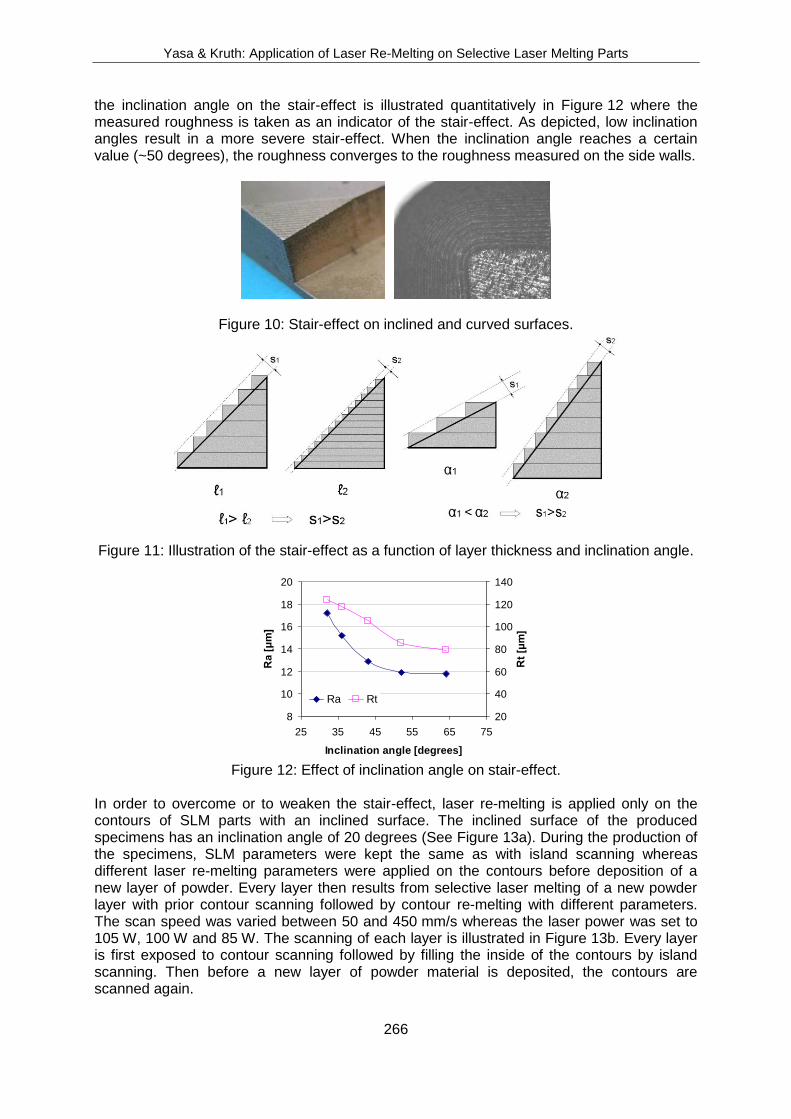
3.3.1 Re-melting the contours only The stair-effect is a limitation for all layer manufacturing techniques for the production of parts with inclined or curved surfaces as depicted in Figure 10. The stair-effect depends on the inclination angle as well as the layer thickness. As the inclination angle is reduced or the layer thickness is increased, the stair-effect becomes more pronounced (See Figure 11 where s is the stair size, ℓ is the layer thickness and α is the inclination angle). The effect of
Yasa & Kruth: Application of Laser Re-Melting on Selective Laser Melting Parts
266
the inclination angle on the stair-effect is illustrated quantitatively in Figure 12 where the measured roughness is taken as an indicator of the stair-effect. As depicted, low inclination angles result in a more severe stair-effect. When the inclination angle reaches a certain value (~50 degrees), the roughness converges to the roughness measured on the side walls.
Figure 10: Stair-effect on inclined and curved surfaces.
Figure 11: Illustration of the stair-effect as a function of layer thickness and inclination angle.
8
10
12
14
16
18
20
25 35 45 55 65 75
Inclination angle [degrees]
Ra
[μ
m]
20
40
60
80
100
120
140
Rt
[μm
]
Ra Rt
Figure 12: Effect of inclination angle on stair-effect.
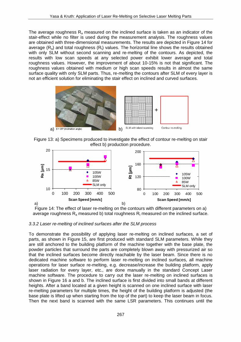
In order to overcome or to weaken the stair-effect, laser re-melting is applied only on the contours of SLM parts with an inclined surface. The inclined surface of the produced specimens has an inclination angle of 20 degrees (See Figure 13a). During the production of the specimens, SLM parameters were kept the same as with island scanning whereas different laser re-melting parameters were applied on the contours before deposition of a new layer of powder. Every layer then results from selective laser melting of a new powder layer with prior contour scanning followed by contour re-melting with different parameters. The scan speed was varied between 50 and 450 mm/s whereas the laser power was set to 105 W, 100 W and 85 W. The scanning of each layer is illustrated in Figure 13b. Every layer is first exposed to contour scanning followed by filling the inside of the contours by island scanning. Then before a new layer of powder material is deposited, the contours are scanned again.
Yasa & Kruth: Application of Laser Re-Melting on Selective Laser Melting Parts
267
The average roughness Ra measured on the inclined surface is taken as an indicator of the stair-effect while no filter is used during the measurement analysis. The roughness values are obtained with three-dimensional measurements. The results are depicted in Figure 14 for average (Ra) and total roughness (Rt) values. The horizontal line shows the results obtained with only SLM without second scanning and re-melting of the contours. As depicted, the results with low scan speeds at any selected power exhibit lower average and total roughness values. However, the improvement of about 10-15% is not that significant. The roughness values obtained with medium or high scan speeds results in almost the same surface quality with only SLM parts. Thus, re-melting the contours after SLM of every layer is not an efficient solution for eliminating the stair effect on inclined and curved surfaces.
a) b)
Figure 13: a) Specimens produced to investigate the effect of contour re-melting on stair effect b) production procedure.
a)
10
15
20
0 100 200 300 400 500
Ra
[µ
m]
Scan Speed [mm/s]
105W
100W
85W
SLM only
b)
80
120
160
200
0 100 200 300 400 500
Rt
[µm
]
Scan Speed [mm/s]
105W100W85WSLM only
Figure 14: The effect of laser re-melting on the contours with different parameters on a) average roughness Ra measured b) total roughness Rt measured on the inclined surface.
3.3.2 Laser re-melting of inclined surfaces after the SLM process To demonstrate the possibility of applying laser re-melting on inclined surfaces, a set of parts, as shown in Figure 15, are first produced with standard SLM parameters. While they are still anchored to the building platform of the machine together with the base plate, the powder particles that surround the parts are completely blown away with pressurized air so that the inclined surfaces become directly reachable by the laser beam. Since there is no dedicated machine software to perform laser re-melting on inclined surfaces, all machine operations for laser surface re-melting, e.g. decrease/increase the building platform, apply laser radiation for every layer, etc., are done manually in the standard Concept Laser machine software. The procedure to carry out the laser re-melting on inclined surfaces is shown in Figure 16 a and b. The inclined surface is first divided into small bands at different heights. After a band located at a given height is scanned on one inclined surface with laser re-melting parameters for multiple times, the height of the building platform is adjusted (the base plate is lifted up when starting from the top of the part) to keep the laser beam in focus. Then the next band is scanned with the same LSR parameters. This continues until the
Yasa & Kruth: Application of Laser Re-Melting on Selective Laser Melting Parts
268
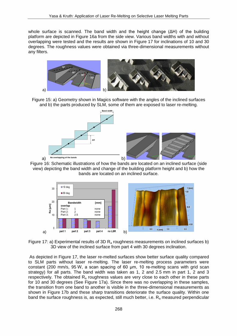
whole surface is scanned. The band width and the height change (ΔH) of the building platform are depicted in Figure 16a from the side view. Various band widths with and without overlapping were tested and the results are shown in Figure 17 for inclinations of 10 and 30 degrees. The roughness values were obtained via three-dimensional measurements without any filters.
a) b)
Figure 15: a) Geometry shown in Magics software with the angles of the inclined surfaces
and b) the parts produced by SLM, some of them are exposed to laser re-melting.
a) b) Figure 16: Schematic illustrations of how the bands are located on an inclined surface (side view) depicting the band width and change of the building platform height and b) how the
bands are located on an inclined surface.
a) b)
Figure 17: a) Experimental results of 3D Ra roughness measurements on inclined surfaces b)
3D view of the inclined surface from part 4 with 30 degrees inclination.
As depicted in Figure 17, the laser re-melted surfaces show better surface quality compared to SLM parts without laser re-melting. The laser re-melting process parameters were constant (200 mm/s, 95 W, a scan spacing of 60 µm, 10 re-melting scans with grid scan strategy) for all parts. The band width was taken as 1, 2 and 2.5 mm in part 1, 2 and 3 respectively. The obtained Ra roughness values are very close to each other in these parts for 10 and 30 degrees (See Figure 17a). Since there was no overlapping in these samples, the transition from one band to another is visible in the three-dimensional measurements as shown in Figure 17b and these sharp transitions deteriorate the surface quality. Within one band the surface roughness is, as expected, still much better, i.e. Ra measured perpendicular
Bandwidth [mm] overlap
Part 1: 1 none Part 2: 2 none Part 3: 2.5 none Part 4: 2 yes

Yasa & Kruth: Application of Laser Re-Melting on Selective Laser Melting Parts
269
to the bands on the inclined surface of 10 degrees in part 2 is 8.19 µm, whereas it reduces to 5.18 µm when measured within one band (i.e. parallel to the bands). This also holds true for the roughness Rt values. In order to overcome this problem, overlapping (~50%) of the bands was employed in part 4 where the band width was kept as 2 mm. This resulted in even lower roughness values. As a result of these tests, it is concluded that a larger band is better for small slope surfaces to avoid many transitions. Even with larger bands, it is useful to employ overlapping to overcome severe transition regions with deep valleys in between the bands. If the inclination is significant, the height should be manually adjusted more often to keep the laser beam in focus. Therefore, smaller band widths are necessary with steeply inclined surfaces. The smallest band width tested in this experimental work was 0.5 mm but that was even not small enough for the surfaces having an angle of 70 degrees. However, all the other three inclined surfaces having angles of 10, 30 and 50 degrees were significantly improved in terms of surface quality. The enhancement was about 70%. This work proves that laser re-melting can also be applied to inclined and curved surfaces.
4. CONCLUSIONS In this study, laser re-melting is used to improve the selective laser melting (SLM) process in terms of surface quality and density. Unlike Selective Laser Sintering, SLM can produce very high density parts even without any additional post-processing. The density of produced samples by SLM can reach up to 98-99%. However, for some applications, the remaining porosity may be a significant problem. When laser re-melting is applied after each layer with suitable parameters, the porosities mostly disappear leaving a very dense microstructure at a cost of longer production times. Moreover, laser re-melting can greatly enhance the surface quality of SLM parts which is generally an important limitation (about 90%). The possibility of eliminating or surpressing the stair-effect by laser re-melting the layer contours is also demonstrated. However, the stair-effect is only reduced by 10-15% when laser re-melting is only applied on the layer contours. The stair-effect was also targeted by applying laser re-melting on the inclined surfaces after the SLM process is completed and the surrounding powder particles are totally blown away. In this case, the improvement was much more significant and a reduction about 70% in the average roughness was achieved.
ACKNOWLEDGEMENTS The authors thank TUBITAK (The Scientific and Technological Research Council of Turkey) for its financial support given under “Ph.D. support program for students in foreign countries”. The authors also thank K.U.Leuven for the support through the project GOA/2002-06 and IWT for the support through the SBO-project DiRaMaP.
REFERENCES [1] Kruth, J.-P., Froyen, L., Van Vaerenbergh, J., Mercelis, P., Rombouts, M., Lauwers, B. (2004).
Selective Laser Melting of iron-based powder, Journal of Materials Processing Technology, Vol. 149, 616-622
[2] Henari, F.Z., Blau, W. (1995). Excimer-laser surface treatment of metals for improved adhesion, Applied Optics, Vol. 34, 581–584
f3] Nicolas, G., Autric, M., Marine, W., Shafeev, G.A. (1997). Laser induced surface modifications on ZrO ceramics, Applied Surface Science, Vol. 109-110, 289–292
[4] Triantafyllidis, D., Li, L., Stott, F.H. (2005). The effects of laser-induced modification of surface roughness of Al2O3-based ceramics on fluid contact angle, Materials Science and Engineering A, Vol. 390, 271-277
[5] Lamikiz, A., Sanchez, J.A., Lopez de Lacalle, L.N., Arana, J.L. (2007). Laser polishing of parts built up by selective laser sintering, Machine Tools and Manufacture, Vol. 47, 2040-2050
Yasa & Kruth: Application of Laser Re-Melting on Selective Laser Melting Parts
270
[6] Ramos-Grez, J.A., Bourell, D.L. (2004). Reducing surface roughness of metallic freeform-fabricated parts using non-tactile finishing methods, International Journal of Materials and Product Technology, Vol. 21, 297-316
[7] Kac, S., Kusinki, J. (2004). SEM structure and properties of ASP2060 steel after laser melting, Surface and Coatings Technology, Vol. 180-181, 611-615
[8] Pinto, M.A., Cheung, N., Ierardi M.C.F., Garcia, A. (2003). Microstructural and hardness investigation of an aluminum-copper alloy processed by laser surface melting, Materials Characterization, Vol. 50, 249-253
[9] Xianqing, Y., Chengjun, Z., Xuefeng, S., Manping, H., Jianguo, M. (2007). Microstructure evolution of WC/steel composite by laser surface re-melting, Applied Surface Science, Vol. 253, 4409-4414
[10] Zhang, Y., Chen, J., Lei, W., Xv, R. (2008). Effect of laser surface melting on friction and wear behaviour of AM50 magnesium alloy, Surface and Coatings Technology, Vol. 202, 3175-3179.
[11] Felgueroso, D., Vijande, R., Cuetos, J.M., Tucho, R., Hernandez, A. (2008). Parallel laser melted tracks: Effects on the wear behaviour of plasma-sprayed Ni-based coatings, Wear, Vol. 264, 247-263
[12] Tang, C.H., Cheng, F.T., Man, H.C. (2004). Improvement in cavitation erosion resistance of a copper based propeller alloy by laser surface melting, Surface and Coatings Technology, Vol.182, 300-307
[13] Xu, W.L., Yue, T.M., Man, H.C., Chan, C.P. (2006). Laser surface melting of aluminium alloy 6013 for improving pitting corrosion fatigue resistance, Surface & Coatings Technology, Vol. 200, 5077-5086
[14] Guozhi, X., Jingxian, Z., Yijun, L., Keyu, W., Xiangyin, M., Pinghua, L. (2007). Effect of laser remelting on corrosion behavior of plasma-sprayed Ni-coated WC coatings, Materials Science and Engineering A, Vol. 460-461, 351-356
[15] Lawrence, J., Li, L. (2001). A laser based technique for the coating of mild steel with a vitreous enamel, Surface and Coatings Technology, Vol. 140, 238-243
[16] Hao, L., Lawrence, J. (2006). Effects of Nd:YAG laser treatment on the wettability characteristics of a zirconia based bioceramic, Optics and Lasers in Engineering, Vol. 44, 803-814
[17] Grabowski, A., Formanek, B., Sozanska, M., Nowak, M. (2006). Laser remelting of Al-Fe-TiO3 composite powder incorporated in an aluminum matrix, Journal of Achievements in Materials and Manufacturing Engineering, Vol. 18, No.1-2, 95-98
f18] Rombouts, M. (2006). Selective Laser Sintering/Melting of iron-based powders, PhD Thesis, Katholieke Univesiteit Leuven, Belgium
[19] Morgan, R.H., Papworth, A.J., Sutcliffe, C., Fox, P., O’Neill, W. (2002). High density net shape components by direct laser re-melting of single phase powders, Journal of Materials Science, Vol. 37, 3093-3100
[20] Braga, F.J.C., Marques, R.F.C., Filho, E.A., Guastaldi, A.C. (2007). Surface modification of Ti dental implants by Nd:YVO4 laser irradiation, Applied Surface Science, Vol. 253, 9203-9208.
[21] Yasa, E., Kruth, J.-P., Deckers, J. (2008). Roughness improvement in selective laser melting, Proceedings of PMI Conference, Ghent, Belgium
[22] Yasa, E. (2011). Manufacturing by combining Selective Laser Melting and Selective Laser Erosion / Laser Re-melting, PhD Thesis, Katholieke Univesiteit Leuven, Belgium


![University of Birmingham Selective laser melting of AlSi10Mg alloy: Process … · 2018. 11. 29. · laser fabrication (DLF), and selective laser melting (SLM) [5, 6]. Aerospace manufacturers](https://img.dokumen.tips/doc/110x75/606f2d4d983f986eb3388e9a/university-of-birmingham-selective-laser-melting-of-alsi10mg-alloy-process-2018.jpg)


![Surface Morphology in Selective Laser Melting of Metal Powders · 2017. 1. 23. · selective laser melting. Based on previously experimental results [8], the laser irradiation parameters](https://img.dokumen.tips/doc/110x75/60b33a662dca0e345c03e8ff/surface-morphology-in-selective-laser-melting-of-metal-powders-2017-1-23-selective.jpg)