Embed Size (px)
Citation preview

APPLICATION OF FUEL CELLS IN SURFACE SHIPS
ETSU F/03/00207/REP
DTI/Pub URN 01/902
ContractorRolls-Royce Strategic Systems Engineering
Prepared byC Bourne (RR-SSE)T Nietsch (RR-SSE)
Dave Griffiths (RR-MP) Jon Morley (RR-MP)
The work described in this report was carried out under contract as part of the DTI Sustainable Energy Programmes. The views and judgements expressed in this report are those of the contractor and do not necessarily reflect those of the DTI.
First published 2001 © Crown copyright 2001

ContentsSummary..........................................................................................................................
1 Market Analysis........................................................................................................11.1 Introduction......................................................................................................11.2 Methodology.................................................................................................... 31.3 Assumptions and Caveats............................................................................... 31.4 SUMMARY............................................................................................................ 5
2 Market Trends And Requirements........................................................................ 92.1 Market Trends...................................................................................................92.2 Technology......................................................................................................102.4 Environmental Legislation..........................................................................132.5 Safety Legislation and Machinery Classification...................................152.6 Manning............................................................................................................162.7 IMPROVEMENTS IN PERFORMANCE.................................................................... 16
3 State of the Art Review.......................................................................................... 193.1 Military Development Programmes............................................................. 193.2 Civil Development Programmes.................................................................. 243.3 State of the Art of Key Components.......................................................... 273.4 IMPROVEMENTS IN THE NEAR AND MEDIUM FUTURE.............................................38
4 Fuel Cells vs Diesel engines and gas turbines...................................................... 404.1 Thermal Efficiency and Fuel Consumption............................................... 404.2 PART LOAD EFFICIENCY / SPECIFIC FUEL CONSUMPTION VS LOAD....................... 424.3 Economics........................................................................................................ 454.4 Gravimetric and Volumetric Power Density............................................ 454.5 Maintenance................................................................................................... 474.6 EMISSIONS.......................................................................................................... 484.7 NOISE................................................................................................................. 514.8 SUMMARY.......................................................................................................... 51
5 Applicability Of Fuel Cells To Propulsion Systems............................................ 535.1 Generic Vessel Types..................................................................................... 535.2 Examples of proposed fuel cell installations............................................64
6 Target Performance Criteria................................................................................ 716.1 Cruise ship....................................................................................................... 716.2 Cargo ship........................................................................................................ 726.3 Offshore vessel.............................................................................................. 73
7 Barriers To Implementation................................................................................. 75
7. 1 Maturity of Technology................................................................................757.2 Fuel Issues....................................................................................................... 767.3 Classification................................................................................................. 777.4 Resistance to Flood, Fire and Collision.................................................... 787.5 Operation and Degradation......................................................................... 797.6 Ship Integration Issues.................................................................................. 79
i

7.7 SUMMARY........................................................................................................................................82
8 Conclusions..............................................................................................................83
REFERENCES ............................................................................................................ 86
APPENDICES..................................................................................................................
A.1 INTER-CONTINENTAL CARGO VESSEL.......................................
A.2 COASTAL CARGO VESSEL...............................................................
A.3 PASSENGER CRUISE VESSEL..........................................................
A.4 SHORT HAUL / RAPID TURN AROUND FERRY...........................
A.5 RESEARCH & SURVEY VESSEL.......................................................
A.6 OFFSHORE SUPPORT & SPECIALIST APPLICATION VESSEL
A.7 LEISURE CRAFT...................................................................................
A. 8 TOURIST CRAFT................................................................................
B. 1 TYPICAL SLOW SPEED DIESEL ENGINE SYSTEM..............
B.2 TYPICAL MEDIUM SPEED DIESEL ENGINE SYSTEM...........
B.3 TYPICAL HIGH SPEED DIESEL ENGINE SYSTEM .................
B.4 TYPICAL SIMPLE CYCLE GAS TURBINE SYSTEM.................
B.5 ADVANCED CYCLE GAS TURBINES............................................
ii

Summary
This report presents the findings of a DTI supported project entitled: “Applications of fuel cells in surface ships”.
It gives a brief market analysis describing the general requirements of different vessel types and an overview of the different heat engine technologies currently used for propulsion and power generation in ships. The appendices contain a more detailed description of the different vessel types, their general requirements and a description of current prime mover technologies used.
This analysis is followed by a summary of the major fuel cell development programmes and activities ongoing in different countries that have a direct or potential relevance to a marine application of the technology.
Whilst many of the programmes referred to in this report are military driven they are worthy of broader consideration as the perceived benefits of higher efficiency, lower noise etc. are similarly attractive to many civil applications. To date much of the activity has been concentrated in the USA, but Europe is steadily increasing its efforts. As could be expected, civil activities tend to be more collaborative than military ones.
This review is followed by a summary of the characteristics and development status of Polymer Electrolyte (PEMFCs), Molten Carbonate (MCFCs) and Solid Oxide (SOFCs) Fuel Cell systems.
The report goes on to compare and contrast, in general terms, the characteristics and properties of fuel cells with those of diesel engines and gas turbines. The main focus here is on efficiency, power density, emissions and costs.
The report concludes that the key advantage fuel cells offer is the possibility of improving efficiency. However whilst the theoretical efficiency of a fuel cell exceeds that achieved using conventional technology (unless extensive use of combined cycle techniques are possible), the actual efficiencies realised by prototype plants are roughly equivalent to the better medium and slow speed diesel engines
Fuel cells need to demonstrate that they can beat the best performance of current heat engines, ~ 50% efficiency, and that they have the potential for an additional 10 - 15% increase in order to show a clear and sustainable advantage over conventional technologies. If this is achieved, then fuel cells are likely to be a desirable power source, as many vessels will make some sacrifice in terms of power density if fuel savings can be realised.
If these efficiency targets are not met, then fuel cells will only be able to target niche markets for specialist application where their other characteristics, such as low noise and vibration, have value. In all other respects the advantages of fuel cells are either not relevant to the application or diesels and gas turbines have a distinct performance advantage.
iii

Of the three technologies considered SOFCs appear to offer the most promise. In comparison, the efficiency advantage of PEMFCs over conventional heat engines is marginal and highly dependent on the choice of fuel and though MCFCs are a more mature technology than SOFCs they suffer from significantly higher weight and volume.
The most significant barrier to entry which fuel cells have to overcome is the suitability of available fuels. If as expected, logistics and economics continue to encourage owners to run their vessels (at least in the foreseeable future) on heavy fuel or marine fuel oil, than a major development effort is required to process these into “fuel cell friendly” fuels.
iv

1 Market Analysis
1.1 Introduction
AimThe aim of this assessment is to provide an understanding of the potential market for fuel cell technology as a part of commercial marine power generation / propulsion systems.
ScopeThe assessment includes a snapshot of the current market breakdown as evaluated by the following basic ship categories:• Inter-Continental Cargo Ships• Coastal Cargo Ships• Passenger cruise Ships• Short haul Ferries (both conventional and “fast” ferries)• Research and Survey Ships• Offshore Support ships• Leisure Craft• Tourist Craft
The generic requirements for the propulsion systems for these vessel types have been assessed on a qualitative basis to provide “ideal requirements”. The performance trends of current prime movers, typical of current systems have been analysed and described, see appendix A.
Market BreakdownThe marine market is really a collection of sub-markets, each with its own drivers and forces acting upon it. Each of the sub markets offers numerous market solutions, driving a diversity of vessel designs and sizes. An indication of the breadth of sizes for each of the major sub-markets is given below:
Cruise Vessel
Fast Ferry
Ferry
RoRo
Reefer
Container Vessel
Bulk Carrier
Crude Oil Carrier
Produce Carrier
Chemical Carrier
LNG/LPG
1
20000 40000 60000 80000 100000 120000 140000 160000
GRT
Figure 1: Marine market by Gross Registered Tonnage [19]
1

Cruise Vessel
Fast Ferry
Ferry
RoRo
Reefer
Container Vessel
Bulk Carrier
Crude Oil Carrier
Produce Carrier
Chemical Carrier
LNG/LPG
10 20 30 40 50
Power (MW)60 70 80
Figure 2: Breakdown of the Marine market by installed power
The difference in vessel size, the route it operates, the perishable nature of its cargo and the economics of the market served all influence the speed and installed power of the vessel. Typical ranges of powers for different types of vessels are given below:
The two graphs above serve to indicate the diversity of the market that is being assessed and the difficulties in drawing general conclusions.
Marine EnvironmentThe marine environment offers some unique challenges to the market place. The physical impact of the marine environment can never be underestimated. High winds and heavy seas can place incredible loading on ships, their crews and their cargoes. Indeed the loss of the bulk carrier Derbyshire, attributed to the failure of a cargo hatch cover in typhoon conditions has been attributed directly the impact of heavy seas crashing onto the foredeck area of the vessel. Even without a structural failure, the impact of bad conditions on the operation of a ship can lead to an increased risk of accident through collision with other vessels or land.
Additional physical burdens result from the corrosive nature of the salt present in the marine environment. This requires careful consideration for the selection of materials and the use of preservation measures. Additionally the impact of corrosion on systems, from a safety point of view, needs to be very carefully assessed.
The operation of the major areas of the market is such that the ships are away from land for considerable periods. This requires a high degree of self reliance, as provision of support from ashore becomes a highly expensive exercise.
2

Consequently, whilst machinery availability is the desired criteria, for a lightly manned vessel with no external support, reliability is crucial, rather than achieving availability through rapid maintenance.
In addition, many operators look to undertake maintenance onboard to reduce the time the vessel is alongside and not operational.
1.2 Methodology
The market assessment has been conducted to support investigations into the feasibility of adopting fuel cells for marine applications. The approach adopted has been to establish and define an understanding of the current marine market, the requirements it places on propulsion systems, the trends affecting it, and the direction it is likely to follow in the near future. In parallel, the technologies typical of today’s vessels have been investigated, the means by which they strive to meet the requirements placed on them have been discussed, and their performance described. Predictions of future developments have been added to these performance levels to provide a set of target criteria for fuel cells to achieve. These criteria could be viewed, as the ideal capabilities required of fuel cells if they are to break into the marine market.
1.3 Assumptions and Caveats
Where possible, manufacturers data have been used to form a variety of sources to establish typical performance trends. These trends are not intended to represent specific performance capabilities or targets, but to establish the likely levels of performance that a competitor technology will need to reach in order to stand a chance of breaking into the market.
Due to the incredible diversity of types of vessels, the roles they fulfil and the economic and other factors influencing them, propulsion systems tend to be bespoke for a given ship design. That said there are a number of trends evident in the design drivers for propulsion systems. The study has developed a number of “generic propulsion” systems based on the types of systems typical to ships operating today. However, it is acknowledged by the authors and must be appreciated by the reader that the art of designing a propulsion system is particular to a ship, the cargo it will carry, and the region in which it will operate and the dynamics of the markets it serves. Consequently any generic systems described are offered as no more than examples of the technologies and systems in place in the marine market.
Despite the wide variety of system designs, there are significant areas of common ground. Basically, whatever power plant is selected, it must provide mechanical energy to the propulsion train which converts it into thrust into the water. Whilst the shaftline efficiency is marginally dependent on the input characteristics, the actual system efficiency is dominated by the efficiency of the power plant and the propulsor (typically propeller or waterjet).
Of these, assuming the correct propulsor is chosen in the first instance, efficiency of the power plant is the key variable. The efficiency breakdown is approximately as follows:
3

Power plant: 35 - 55%Propulsion train: 98 - 96%1Propulsor: 65 - 75%2
From this it can be seen that if efficiency of the system is a key driver, then theefficiency of the power plant is a dominant factor.
Commercial sensitivity makes obtaining accurate cost data problematic, even more so when there is no method for factoring in regional discounting schemes, the benefits of adopting off the shelf designs and special relationships / partnerships. Therefore, the economic arguments for adopting different generic systems have been included, rather than specific prices. Typically the propulsion system represents approximately 10% of the build cost of the vessel.
The quantity of fuel carried in bunker tanks varies between ships. The requirement is defined by propulsion and power generation system fuel economy and operating profile. Establishing this requirement depends on intimate knowledge of a ship’s usage. Consequently, indicative savings in fuel bunkerage have been indicated where improved fuel efficiency may be achieved. These indicative savings have been defined against operational criteria typical to the ship type.
The following performance criteria have been used:
Fuel economy Defined as specific fuel consumption (SFC)
Reliability Not quantified, but considered in terms of operating time between failures
Maintainability - Not quantified but considered in terms of time andmanpower required rectifying failures
Installation flexibility - Considered in terms of the ease with which systems orcomponents can be installed in a variety of configurations or compartments on a ship
Operational flexibility - Considered in terms of the variety of loads that can beefficiently supplied by a system or power plant
System Response Considered in terms of the rapidity of a systems ability to alter its output following a command to do so
Power Density Power output per unit volume or weight
1 Typically assumed to be constant2 Dependent on the type of propulsor. Efficiency depends on the interaction between
ship hull, the sea and the propulsor itself. For a given hull and constant ship speed the efficiency is constant.
4

Emissions
Noise
Vibration
Adaptability
Quantified where possible in terms of gaseous emission per kWh
The emitted noise from the power plant or system
The emitted vibrations from the power plant or system
Considered in terms of a systems ability to handle different loading profiles
1.4 Summary
It is evident that different ship types have different design drivers and influencing factors relating to the prime movers within the propulsion system. It is these key factors that define the suitability of any prime mover to a specific application based on matching the operational factors and economic concerns of the ship owners and operators, with the operating economics and characteristics of prime movers.
The following tables rank the various performance criteria for each type of vessel and each prime mover, where a score of 1 is a key design driver and 3 indicates that a minimum level of compliance is sought. Comparison between the two allows the more desirable prime movers for a given application to be highlighted. This can be seen in the third table, reflecting the market breakdown. A more detailed description of different vessels can be found in Appendix A.
5

Ship Type
Fuel
Eco
nom
y
Rel
iabi
lity
Mai
ntai
nabi
lity
Flex
ibili
ty
Rap
id R
espo
nse
Pow
er D
ensit
y
Ava
ilabi
lity
Low
Em
issio
ns3
Low
Noi
se /
Vib
ratio
n
Ada
ptab
ility
Cos
t
Intercontinental Cargo Ship 1 1 1 3 3 3 1 3 3 3 2Coastal Cargo Ship 1 1 1 1 1 2 1 2 3 3 1Passenger Cruise Ship 2 1 2 1 2 3 1 1 1 1 3Ferry - Conventional 1 1 1 1 1 2 1 2 2 2 1Ferry - Fast 3 1 3 2 1 1 1 2 2 3 3Research and Survey Vessel 2 1 2 1 1 2 1 3 1 1 3Offshore Support Vessel 2 1 2 1 1 2 1 3 2 1 3Leisure Craft 3 2 3 3 1 1 1 2 2 3 3Tourist Craft 1 1 1 2 1 1 1 1 1 3 1
Table 1: Performance criteria
Prime Mover
Fuel
Eco
nom
y
Rel
iabi
lity
Mai
ntai
nabi
lity
Flex
ibili
ty
Rap
id R
espo
nse
Pow
er D
ensit
y
Ava
ilabi
lity
Low
Em
issio
ns
Low
Noi
se /
Vib
ratio
n
Ada
ptab
ility
Cos
t
Slow Speed Diesel 1 1 1 3 3 3 1 3 3 3 3Medium Speed Diesel 1 1 1 1 1 2 1 2 3 3 2High Speed Diesel 2 1 2 1 2 3 1 1 1 1 1Simple Cycle Gas Turbine 1 1 1 1 1 2 1 2 2 2 2Advanced Cycle GasTurbine
3 1 3 2 1 1 1 2 2 3 3
High Temperature Fuel Cell 2 1 2 1 1 2 1 3 1 1Low Temperature Fuel Cell 2 1 2 1 1 2 1 3 2 1
Table 2: Prime Mover Performance
3 Whilst international statutory legislation must be complied with, the issue of state legislation is less clear. Some ports levy fines on vessels deemed to be “dirty” based on their own national legislation. Additionally, the high visibility of some types of vessel to the public requires performance beyond that required by legislation, particularly in the case of particulate emissions.
6

Using this rationale, it is clear that identifying the suitability of a specific prime mover to a specific marine application is possible: provided there is an understanding of the both the specific ships operating profile and prime mover characteristics.
Ship
Typ
e
Slow
Spe
edD
iese
l
Med
ium
Spee
d D
iese
l
Hig
h Spe
edD
iese
l
Sim
ple
Cyc
leG
as T
urbi
ne
Adv
ance
dC
ycle
Gas
Mec
hani
cal
Prop
ulsio
n
Elec
tric
Prop
ulsio
n
Intercontinental Cargo Ship X XCoastal Cargo Ship X X XPassenger Cruise Ship X X X X XFerry - Conventional X X XFerry - Fast X X X XResearch and Survey Vessel X X X X XOffshore Support Vessel X X X X XLeisure Craft X X XTourist Craft X X
Table 3: Typical Prime movers for Ship Types
Prime Mover Performance Data
Performance data for a wide number of prime mover models and types has been extracted from manufacturer’s guides, indicative data and technical articles and papers. The technical data are located in annexes and covers the following categories:
Fuel Consumption - Defined in terms of specific fuel consumption (perkilowatt hour)
Weight - Defined in terms of weight power density
Volume - Defined in terms of volumetric power density
In addition, a discussion of the start up times, response time, typical thermal efficiency, environmental performance of the prime mover and the requirements for typical propulsion systems and auxiliary systems associated with these prime movers is included
The commercial sensitivity of cost data is such that only a minimal amount has been made available for this study. Despite this, discussion on the economics of the various propulsion systems has been included.
It should be noted that any values used are not aimed to be definitive statements of performance, but have been plotted to establish trends across market sectors. It should be understood that the figures used are subject to caveats on operating conditions, fuel quality, machinery rating actual usage requirements etc. However, the trends derived
7

give an understanding of typical performance levels of conventional propulsion machinery.
8

2 Market Trends And Requirements
2.1 Market Trends
The major share of the marine propulsion market (in terms of prime movers) is taken up by diesel engines, representing in excess of 95% of installed power and installed units. Of this, slow speed diesels currently represent some 80% of the marine propulsion market, medium speed diesels some 15% and high speed diesels some 5% (measured by power). Over the last twenty-five years, the slow speed diesel market share has seen an increase from about 60% in 1975, largely at the expense of high-speed diesels, whose market share has fallen from 20% over the same period. The medium speed diesel market share has also seen a decrease, but to a lesser extent, from approximately 20% in 1975 [1].
Gas turbines have gained a toehold in the commercial marine market over the last 10 years or so, but still don’t represent a significant share and tend to be used for specialist applications where space and weight are at a premium.
Over the same period, slow speed diesels have seen a growth in the average power per engine of approximately 30%. Medium speed diesels have seen a growth of average engine size of nearly 75% and high-speed diesels have seen a decrease in the average size of engine by nearly 80%. However, over the last 10 years, the average high-speed diesel engine has increased in power significant, possibly driven by the expansion in the fast ferry market, which makes considerable use of these power dense units.
When considering the power installed onboard large vessels over the last twenty five years, it is difficult to identify any recognisable trends. However, the increase in average engine sizes identified above indicates either a trend toward larger ships, or faster ships (or both).
Bulk carriers have seen a converging trend away from small and large vessels towards vessels of medium (“Handy” and “Panamax”) sizes between 40000 and 80000 dead weight tonnes (dwt4). Typically these vessels have 8 - 15 MW installed power.
Oil and other tankers have seen a significant increase in the demand for 2000 to 20000 dwt vessels, at the expense of the 200000+ dwt (Very Large and Ultra Large Crude Carriers (VLCCs and ULCCs)). The smaller tankers range between 5 to 10 MW installed power as compared to up to 30 - 40 MW for the larger tankers.
For general cargo ships, there is a definite trend towards larger vessels, over 20000 dwt. These vessels typically have an installed power in excess of 10 MW.
4 Dead weight tonnage is a measure of the ship’s loaded weight, given over to cargo, passengers, crew etc. in simple terms that is the difference between a ship’s loaded and unloaded weight (taking note of the fact that vessel’s have a number of safe loaded conditions for different scenarios).
9

Container vessels are becoming ever larger. As they do, there is also an increasing demand for the smaller “Feeder” vessels that distribute cargo from the major container ports served by the larger vessels. This reflects the growth of containerised transportation and the benefits this form of packaging offers in terms of compatibility of offload to trucks and trains for inland distribution. Consequently the larger end of the container ship fleet continues to increase in size beyond 80000 dwt, whilst the smaller end (5 - 20000 dwt) remains buoyant. Typically the larger vessels see installed powers of up to 60 MW and the smaller ones 5 - 11 MW. Future predictions may see installed power grow to in excess of 100 MW [2].
2.2 Technology
This section summarises the main marine prime mover characteristics; a detailed description is given in appendix B.
Diesel enginesThe marine prime mover market is dominated by the diesel engine. Broadly speaking, diesels can be grouped into three types:• Slow speed engines operating on two stroke cycles with crankshaft speeds up to
approximately 200 rpm.• Medium speed engines operating on four stroke cycles with crankshaft speeds
typically in the range 400 - 1200 rpm.• High-speed engines operating on a four stroke cycle with crankshaft speeds in
excess of 1200 rpm.
These boundaries are subjective depending on viewpoint, but have been adopted for the purposes of this assessment. As engine speed increases, a number of general trends in diesel engine performance can be observed:• Power density increases,• Specific fuel consumption increases,• Component wear rate increases,• Power per cylinder decreases.
For a given diesel engine, the specific fuel consumption curve is relatively flat, giving excellent part load performance in terms of fuel consumption. However in general, protracted low load (below approx. 20 - 30 % maximum continuous rating (MCR)) running is to be avoided as it can lead to accumulation of carbon in the cylinders and degradation of the engine and its performance.
Diesel engines tend to be constructed in modular families (e.g. 4, 6, 8, 12, 16 & 18 cylinder variants), offering a wide range of power ratings whilst maximising commonality of components and operating / maintenance procedures.
Diesel engines are also widely used as prime movers for generators. Traditionally separate units from the propulsion engines provide ship’s service electrical power. However vessels operating for long periods at a steady speed use a shaft generator, driven by a power take off from the main engine or propeller shaft. A concept that has gained popularity relatively recently is integrated electric propulsion (see below), where
10

the propeller shafts are driven by motors and the power for propulsion and ship service demands is supplied by a common set of generators. This is not a new concept but recent advances in power electronics have made it an increasingly popular one.
Gas turbinesAn increasingly attractive alternative to marine diesel engines are marine gas turbines, most of which are aero-derivative, though there are (and have been) some significant industrial derivative units at sea.
The major advantages offered by gas turbines over diesels are the exceptional power density (especially at high power ratings), good environmental performance and reduced or simplified onboard maintenance.
The major disadvantage of the gas turbine is a high specific fuel consumption, particularly at part loads. Fuel consumption is the key focus for development of gas turbine performance; inter-cooling and exhaust heat recuperation technologies are being adopted to improve the thermal efficiency of gas turbines.
Gas turbine performance depends significantly on atmospheric temperatures. As air density decreases with increasing temperature, so the work required compressing it to the requisite levels for engine performance increases. This effectively reduces the useful work / energy available from the engine. Additionally, the less dense air represents a reduced air mass flow rate through the engine.
Gas turbines are generally installed in enclosures, providing physical and fire protection for other machinery in the engine room. The enclosures are designed to contain turbine or compressor blade fragments that may burst out of the engine body in the event of a catastrophic engine failure. They are normally gas tight also, to allow the deployment of fixed firefighting facilities.
Gas turbines are generally not available in modular families and currently require careful design to ensure that they operate close to their design rating. Again the incorporation of inter-cooling and recuperation technologies will change this scenario. Another method of getting round the part load problem is to install father and son propulsion machinery, with a cruise diesel or gas turbine for low power operation and a boost gas turbine for high-speed / high power operation.
Gas turbines are also used for power generation in both shipping and offshore platforms. The increase in popularity of integrated electric propulsion has often called for high- powered generator packages, a role well suited to the power dense gas turbine.
2.3 Future Trends
Future Trends for Diesel Engines
Diesel engines have been around for many years now and consequently can be seen to be reaching the peak of their development. That’s not to say that the design and
11

development of the diesel engine has stagnated or slowed, but rather that much of it is now concentrated on refinement of engine performance.
Areas in which designers are concentrating include increased power density and reduced emissions, whilst retaining thermal efficiency (and hence low fuel consumption), reliability and low maintenance.
The drive to increase engine power output without significant weight, space or fuel penalties has focussed on a number of areas. These include better use of fuel through improved combustion in the cylinder, better metering of fuel injection, utilising digital and electronic control and management, increased cylinder pressures and piston speeds, improved turbo charging and compact arrangement of cylinders in vee form engines. Two stroke engines (and four stroke engines) have demonstrated a continual increase in cylinder power, realised through increased bore sizes, increased brake mean effective pressure (BMEP) and increased piston speed. It should be noted however, that the latter leads to increased wear rates and has an impact on the scavenging efficiency of the engine [2]. It is estimated that a realistic efficiency figure achievable through these measures, is around 53 - 54%
The use of exhaust gas turbines, boilers and economisers and the use of low grade exhaust heat for co-generation, space heating and bunker heating, may increase system efficiency to 70%. However, the increasing complexity means that this approach is not well suited to all marine applications and the full efficiency available is rarely utilised.
One major step change that is being researched is the use of water injection into engines to boost the power output. The anticipated thermodynamic improvements from steam injection offer up to 11% increase in diesel efficiency [3] The steam may be generated using the exhaust gas heat and heat rejection from the engine block.
The use of water or steam injection into the engine cycle, whether the injection is directly into the engine or into the fuel prior to the engine, is anticipated to offer a fourfold reduction in NOx. Research is also being conducted into improved combustion, retarded ignition or exhaust treatment to reduce NOx,
Future Trends for Gas Turbines
The key development for gas turbines appears to be the development of advanced cycles or combined cycles in the constraints of a marine application. Advanced / combined cycles offer both improved overall efficiency and improved part load efficiency. Prototype examples include the Combined Gas Turbines Electric and Steam (COGES) designed for the Royal Caribbean “Millennium” class cruise liners and the WR-21 advanced cycle gas turbine. The former installation is based on a simple cycle gas turbine with co-generation equipment, utilise hot exhaust gas to generate steam for power generation, space heating or fresh water generation. The WR-21 incorporates on- engine inter-cooling and exhaust gas heat recuperation to improve the basic cycle, offering a flatter fuel consumption curve over part load conditions and full load efficiency closer to diesel engine performance.
12

Combined cycle benefits of improved power / reduced fuel consumption and low emissions are also sought through the use of steam or water injection. Indeed research into this technology for gas turbines is slightly ahead of that for diesel engines. It is anticipated that the steam injected gas turbine or water injected gas turbine may achieve efficiencies of up to 40% - 52% [4].
Further to these technologies, a significant proportion of marine gas turbines are aero- derivatives, a trend that is likely to continue. Consequently, any developments in the aero-engine business, in terms of the never-ending drive for reduced or simpler maintenance and improved efficiency, are likely to be reflected downstream in the marine market.
2.4 Environmental Legislation
It is estimated that shipping accounts for 14% of global NOx emissions, 5% of global sulphur emissions from fossil fuels and is responsible for some 5-10 % of acid rain in coastal regions. This makes shipping a target for emissions reduction, particularly in the light of the estimated 50% lower emissions levels from automotive engines. Despite this however, it should be noted that in terms of emissions per cargo ton per kilometre, large bulk and container carrying ships are considerably better than automotive transport.
Maritime legislation is developed at both national and international levels. The main body co-ordinating international legislation effective in both international and territorial waters, is the International Maritime Organisation (IMO). National legislation is promoted through local governing bodies (e.g. national or state government) and is effective in territorial waters.
The key piece of IMO environmental legislation is the International Convention for the Prevention of Pollution from Ships, 1973 as Modified by the Protocol of 1978 (MARPOL 73/78). This currently comprises five annexes regulating the discharge of oil, noxious liquids, harmful packaged substances, sewage and garbage respectively. The convention also defines “special areas” e.g. the Red Sea, the Caribbean Sea, Antarctic regions etc. where stricter legislation applies. A sixth annex, giving regulations for the prevention of air pollution is awaiting ratification and a seventh, regulating the transportation of invasive species in bilge water is being drawn up.
MARPOL Annex VI defines acceptable limits for a number of gaseous emissions from vessels. It is required that no ozone depleting substances shall be deliberately emitted.
Further to this ozone depleting substances shall be prohibited from new build vessels, with the exception of hydrochlorofluorocarbons (HCFCs) which are permitted for new build vessels up to 2020.
NOx limits have been defined for marine diesel engines above 130 kW, excluding engines for emergency use, as:
17 g/kWh n<130 rpm45 x n-0'2 g/kWh 130<n<2000 rpm
13

9.8 g/kWh n>2000 rpm
Where n is the crankshaft speed in revolutions per minute [16].
It should be noted that concern was raised during the preparation of the NOx emissions targets as to whether they are sufficient. The above levels will be reviewed five years after the ratification of the Annex to establish whether further reductions are required.
SOX limits have been derived on the basis of fuel sulphur quantity. The Annex sets a limit for fuel sulphur content at 4.5% for general sea and port areas. Within SOX emission control areas, one of the following will be complied with:
Fuel sulphur content of 1.5%, or a total SOx emission level of 6 g/kWh or less (this is to include both propulsion and auxiliary generation diesel engines).
Achieving these figures requires the use of low sulphur fuel. This is inherently more expensive than fuel with standard levels of sulphur (which may well be above the 1.5% maximum). There are also issues relating to the global availability of such fuels.
Currently the only area assessed as a SOx emission control area is the Baltic Sea. Potentially this may be extended to the North Sea and areas designated special areas under existing MARPOL legislation e.g. the Red Sea, the Caribbean Sea, the Antarctic, the Gulf of Aden and the Great Barrier Reef.
During the preparation of Annex VI, it was proposed that the Marine Environmental Protection Committee (MEPC), an international advisory / regulatory body, investigate the impact of CO2 emissions from ships with a view to preparing a set of emissions targets. It is expected that these may be included in the next modification to the MARPOL convention and may be in force by 2015, possibly as early as 2005.
Other key International environmental legislation that affects maritime operations includes:• 1979 Geneva Convention on Long Range Transboundary Pollution• Vienna Protocol of 1985 for the Protection of the Ozone Layer• Montreal Protocol of 1987 on the control of Ozone Depleting Substances• UN Framework Convention on Climate Change, Rio 1992• Kyoto Convention on Air Pollution 1998 (and subsequent modifications).
Whilst international statutory legislation must be complied with, the issue of state legislation is less clear. There is a proliferation of local environmental legislation, not targeted specifically at shipping, particularly in the USA, Scandinavia and the EU. The implications of contravening the limits set by state legislation are currently being explored. Some ports levy fines on vessels deemed to be “dirty” based on their own national legislation. Other states may refuse entry to territorial waters or impound polluting vessels. The financial impact from punitive fines may be relatively straightforward to assess; however, a vessel being seized or refused entry raises complicated economic questions for the ship operator.
14

The impact of non-marine specific legislation, typically state or regional legislation, on the marine market is yet to be tested. However it is widely anticipated that certain states may well try to apply non-marine specific legislation to vessel in port or operating in territorial / coastal waters. This would have major implications on the emissions from ships, implications that would need to be assessed on a destination by destination basis.
In terms of emissions to sea and atmosphere, the general trend is for increasingly stringent requirements for vessel operators, both in terms of limits to be met and actual substances covered by legislation. The key areas of concern being climatic change, acidification of the environment, enrichment of the marine environment, the entry of toxins into the food chain and visual pollution. Even though the NOx emissions code has yet to be ratified, the next tranche of limits is being discussed and emissions levels for CO2 are also being discussed. The significance of these will depend on the targets set. However, once the limits are established, they will be subject to inevitable reductions in the future.
A key issue for the tightening of NOx emission levels is the point at which on engine techniques (low NOx engine designs) are no longer adequate and exhaust gas treatment is required. It is estimated that this switch will increase the yearly engine running cost by a factor of three (maintenance and services, not including the cost of fuel). This may equate to £30000 per year for a typical 1.5 MW auxiliary diesel engine or up to £600000 per year for a typical 14MW main propulsion engine [17]. It is estimated that the cost of supplying reactant to a catalytic reducer for example varies between 0.4 and 0.2 of the fuel cost for typical engines.It is expected that SOX emissions will also be driven down by increased legislation, either in terms of an increasing number of areas designated as SOX emission control areas, or reduced levels of sulphur allowable in marine fuels.
An area not quantified by regulations is public perception. The high visibility of some types of vessel to the public requires performance beyond that required by legislation. This particularly true of vessels operating in coastal or inland waters and luxury passenger vessels, where smoke and particulate emission may create a negative image.
2.5 Safety Legislation and Machinery Classification
The last few decades have seen a rise in safety awareness and the introduction of considerable legislation governing a multitude of safety related topics. The key international legislation is the Safety Of Life At Sea (SOLAS) Convention and the requirements of the international ship classification bodies, such as Lloyd’s Register of Shipping. In addition to this, ships must comply with the national legislation of the state in which they are registered, e.g. the Merchant Shipping Acts (MSA) in the UK. For the purposes of this analysis the key requirements will be for classification of fuel cell based systems by one or more of the international classification societies. These bodies determine the rules governing the safety and fitness for purpose of equipment installed onboard ships, as well as the seaworthiness of the ships themselves.
15

2.6 Manning
Manpower represents a comparatively large cost for ship builders, operators and owners. Consequently, one of the most visible trends in the drive to improve cost effectiveness has been a reduction in manning levels. Primarily this has been achieved by increasing the scope and capability of automated control, monitoring and operating systems, reduction in the requirement for onboard maintenance (planned or emergency) and increased use of information technology for shoreside support of vessels. This trend seems set to continue.
2.7 Improvements in Performance
The other part of the cost effectiveness equation is often represented by system performance. Improvements in performance against a wide range of parameters are continuously being sought, particularly in the following areas:
• Reduction in fuel consumption or increased efficiency• Increased availability and reduced maintenance load through increased reliability
and maintainability (see above)• Simplified installation and removal• Increased power density• Improved environmental performance• Reduced noise and vibrations• Increased automation (see above)
If a system view is taken, then increased performance can be achieved by developing existing technology (the continuous improvement / gradual change process) or by adopting new technologies (the step change process). In practice, both these exercise occur, so whilst advances in gas turbine and diesel engine performance is sought, ship designers and operators are continually on the look out for new technologies that will improve cost effectiveness.
2.8 The “All Electric” Ship
Electric propulsion for ships is not a new concept and for certain sectors of the industry has been a standard system. However, recent advances in power electronics and improvements in electric motor power density have made this option increasingly attractive.
The primary benefit of electric propulsion is that the service and propulsion loads can be supplied by the same set of prime movers. In situations where there are significant fluctuations in propulsion and ship service requirements there is potential for a reduction in installed power, by assessing the maximum power requirement during the operating profile, from an electrical load chart.
Allowing the prime movers to provide the base ship service load, as well as the propulsion load, allows economic operation when the propulsion load is low. This can
16

significantly improve the fuel consumption of the system. Disconnecting the prime movers from the propulsor increases the potential flexibility of the installation of the main machinery (in practice, the weight of the main machinery generally needs to be low in the ship).
The use of an electric propulsion system also allows the new generation of podded propulsors to be utilised. These units consist of motors, directly connected to propellers, installed in azimuthing pods below the hull of the vessel. The manufacturers claim increased efficiency over traditional shaftlines, due to improved hydrodynamic performance of the propeller and reduced drag. In any case, podded propulsors offer benefits in that they negate the need for steering gear or stern thrusters.
The generator sets, either diesel engine or gas turbine driven, may be arranged or combined in numerous manners to suit the space, weight and complexity constraints imposed by the specific hull. The ability to deliver the power by cable rather than mechanical link allows all the power generation machinery to be located in a manner that is unconstrained by the propulsion train
Current electrical systems tend to be ac based as this suits the electric machines used (ac motors being more readily available at the powers required than dc ones and they also impose a much reduced maintenance burden). Arguments have been proposed for dc distribution with inversion for ac supply to motors and other ac users.
The main factors that suggest a dc distribution system can carry power more economically than an ac system are as follows:
• A higher power transmission capacity for the same weight of copper.• A higher operating voltage for the same level of insulation.• All the current flow transfers power.• There are no low frequency skin effects requiring larger conductors to
achieve an acceptable voltage drop between source and consumer.• There are fewer conductors in a dc system.
Integrating the propulsion and electrical power system in this way does however increase the complexity of the electrical system, and requires a high power distribution network to supply power to the electrical propulsion equipment fitted. The arguments for and against electric propulsion for ships may be summarised as:
Potential advantages:
• Increased system efficiency - lower SFC values attainable• Reduced prime mover running hours• Location and installation flexibility• Reduced total installed power needed• Ease of integrating auxiliary propulsion systems• Power fluctuations less significant
17
Potential disadvantages:
• Increased initial cost• Increased hazard avoidance required operating high power electric systems in the
marine environment• Increased electro-magnetic interference• More installed machinery when including whole electrical system• Converters require large cooling demand
The increase in popularity of electric propulsion is of particular interest for this study as fuel cells would be easy to integrate into such a system. When assessing the applicability of fuel cells for other types of propulsion systems, the shift to electric propulsion must be considered.
18
3 State of the Art Review
This section provides background on:
• The current interest in applying Fuel Cells to marine applications.• The development status of fuel cell technologies, systems and key components
The majority of Fuel Cell marine technology programmes are driven by the perceived benefits that such systems may have in military applications. Some of the most recent or significant programmes are summarised below.
3.1 Military Development Programmes
A. US Office of Naval Research Programme
In 1997, the US Office of Naval Research (ONR) started an advanced developmentprogramme to demonstrate a ship service fuel cell power generator module (SSFC) [5].
The programme currently consists of three phases:
Phase 1 - which finished in 1999, had two principal objectives,
• To generate conceptual designs of a 2.5 MWe SSFC (Ship Service Fuel Cell) power plant in order to assess the characteristics and performance of such systems against conventional heat engine alternatives
• To demonstrate the performance of critical components to reduce the future development risk. This included testing fuel cell cathode tolerance to salt laden air, shock and vibration tests of cell hardware and demonstration of reforming and desulphurisation technologies using logistic fuels.
The systems conceptual design criteria were:
• Provide 2.5 MWe net electrical power at 450 VAC, 3 phase 60 Hz• Run on NATO F-76 fuel (distillate)• Achieve minimum system efficiency of 40% at 50% of rated load (comparable to
marine diesels)• Achieve systems size and weight goals of 57 l/kWe (0.057 m3/kWe) and 18 kg/kWe
(comparable to marine diesels engines and stationary power generators)• Achieve estimated costs in production of $1500/kWe (Approximately £1000/kWe -
somewhat cheaper than large marine diesels)• Be developed using commercial or near-commercial technologies• Be highly reliable and maintainable• Self-sustaining in terms of water and auxiliary energy
Note: No design criteria for efficiency or durability are given in [5]
19

Two consortia were awarded this development programme. One is based on Ballard’s PEMFC technology, the other on Fuel Cell Energy’s MCFCs.
PEMFC
The consortium investigating PEMFC based systems contains the following partners:
• McDermott Technology Inc• BWX Technologies• Ballard Power Systems• Gibbs & Cox.
The system concept, shown in Figure 3, uses an autothermal reformer (ATR) followed by a series of gas clean up units (removal of CO and H2S) and the PEM fuel cell itself.
Desulphurisation is carried out in a regenerable sorbent bed and a polishing sulphur sorbent bed. This arrangement has the potential to reduce the sulphur content to less than 1 ppm. The CO is removed by water-gas shift in high and low temperature reactions and completed by selective oxidation of CO over precious metal catalysts. The unused fuel is burned to drive a turbocompressor (to provide air for the fuel cell) and to recover compression work. An extensive heat exchanger network is required to achieve system wide water and energy balance.
Figure 3: 2.5 MWe ship service PEM fuel cell generator [5]
Major results obtained for PEMFCs so far are summarised below:
Salt air trialsBallard have conducted a number of salt air trials, containing 50 ppm salt on a 10 cell PEM fuel cell stack. Limited (10 hour) tests did not reveal any adverse affects on cell performance. Long term durability tests are obviously needed before the requirement for
20

special arrangements, such as salt filters or louvers, can be assessed. This work will be described in more detail later.
Shock and vibration testThe fuel cell stacked showed no performance degradation in the shock (MIL -S-901D) and vibration (MIL-167-1) environments. PEM fuel cells are, according to these results, qualified for military marine service, with respect to shock and vibration hardening, as either critical or ancillary equipment, with or without shock migration in place.
Fuel processor demonstrationA 20 kWe autothermal fuel processor was built and evaluated. Tests included fuel rates of 2.5 and 5 kg/h at steam to carbon ratios of 3.5. The cold gas efficiency exceeded 95 % for all test conditions and 100 % of the F-76 fuel used was converted into CH4, CO2 and CO. No long-term tests results have been reported.
ConclusionPhase 1 of the projects confirms the potential suitability of PEM fuel cells for shipboard applications.
MCFC
Fuel Cell Energy [6] is conducting a conceptual study based on its direct carbonate fuel cell technology. This system is in the early commercialisation stage for land based applications. They ran a 250 kWe demonstration plant for 10,000 h. It is believed that they achieved a power density of 1200 W/m2 and a degradation of 0.2 %/1000 h.
A design concept for a 2.5 MWe MCFC system was developed. It contains four 625 kWe modules delivering power in parallel to the ship service 450 V bus. Each 625 kWe module incorporates two fuel cell stacks in parallel providing 450 to 600 V dc to the power conditioning system, see Figure 4.
The fuel processing system desulphurises NATO F-76 fuel and converts it to a methane rich gas, which can be used directly in the MCFC. The required steam is generated using waste heat from the fuel cell cathode exhaust; the water required for steam generation is recovered from the fuel cell anode exhaust. Under trials, a FCE MCFC stack has demonstrated similar residence to shock, vibration and salt as the PEMFC system.
STEAM
* '1 -1 %
FUEL
STACK
NATOWATER
RECOVERYFUEL
CONDENSER
ELECTROLYZER
WATER
21

Figure 4: 2.5 MWe Ship Service Power Plant based on a MCFC [6]
Phase 2 & 3
The next two phases under the ONR programme are summarised below:
Phase 2 is scheduled for completion in 2003 and will build and test a nominal 625 kWe SSFC MCFC module. The MCFC was selected because of its higher net electrical efficiency of ~50 % compared to ~40 % of the PEMFC system. This unit will be both land and sea tested.
Phase 3 will be the demonstration that the technology can be effectively meet the power requirements operating on logistic fuel whilst in a marine environment.
B. European Navies programme
It is believed that a number of European Navies have either already launched a similar programme to the US activity although no information is available in the open literature.
This project will probably be based on Ansaldo’s MCFC technology for land based power generation. The technology has already been demonstrated at 100 kWe in the European Commission supported “MOLCARE” project. The "proof of concept” system was tested for 7 months and showed the potential to achieve 47 % electrical efficiency. The second phase of the work recently started aims to demonstrate that this technology is ready for the transition from proof of concept to pre commercialisation.
C. Canadian Department of National Defence (DND) programme
The DND has supported the development of PEMFC technology since the mid 1980s.
The DND embarked on a proof of concept development stage with the building of air independent propulsion, exploratory development module (XDM), for use in submarines. The Canadian company, Ballard, was awarded a contract to design, build and test a 40 kWe PEMFC power plant.
This plant incorporates a fuel processor for diesel and gas clean-up system, which has a number of new features, such as a 30 bar differential pressure membrane clean-up system that delivers hydrogen to the stack at 8 bar, and offers a very compact design.
Heat for reforming is supplied by an internal heat exchanger using a thermal fluid as media. The Canadian DND plants to build a 400 kWe land based demonstrator in the near future.
D. German Navy
German Navy has ordered four partially PEMFC powered class U-212 submarines. These are hybrid systems, incorporating a fuel cell, a diesel engine and lead acid
22
batteries. The fuel cell system consists of nine PEMFC modules of the Siemens 30 to 50 kWe type and will run on pure hydrogen, stored in metal hydrides, and oxygen, stored as a liquid. The use of methanol and silver palladium diffuser systems for generating hydrogen has been investigated as an option by the shipyard, Howald Weke Deutsche Werft (HDW).
HDW started development work on a methanol reformer in the late 90s and it is understood that a complete system for series production will be ready within the next 8 years.
Siemens will deliver the 300 kWe PEMFC stack and HDW will supply the balance of the fuel cell system. Production of the first boat in the class began in summer 1998. Two additional boats are being built to HDW plans at the Fincantieri shipyards for the Italian Navy. The PEMFC system will be built by HDW and delivered to Italy as a complete system.
This will be the first military use of PEMFCs in large marine vessels. HDW now has a fully operational air independent propulsion system on the basis of PEMFC in series production. The net electrical system’s efficiency is between 65 and 70 % on H2/O2.
Siemens has meanwhile almost concluded the development of 120 kWe PEMFC modules for a second generation system for the German Navy. These modules achieve four times the power density of the existing 34 kWe units. Two such modules together will make up the nucleus of a 240 kWe standard PEMFC for future submarines.
German Navy has ordered four partially PEMFC powered class U-212 submarines. These are hybrid powered systems, incorporating a fuel cell, a diesel engine and lead acid batteries. The fuel cell system consists of nine PEMFC modules of the Siemens 30 to 50 kWe type and will run on pure hydrogen stored in metal hydrides and oxygen stored as a liquid. Siemens will deliver the 300 kWe PEMFC modules and Howaldtswerke-Deutsche Werft (HDW) will supply the fuel cell system. The production of the submarines began in summer 1995. Two additional boats are being built to HDW plans at the Fincantieri shipyards for the Italian Navy. The PEMFC system will be built by HDW and delivered to Italy as a complete system.
This will be the first military use of PEMFCs in the marine environment and HDW now has a fully operational air independent propulsion system on the basis of PEMFC in series production. The net electrical system’s efficiency is between 65 and 70 %.
Siemens has meanwhile concluded the development of 120 kWe PEMFC modules for equipping the submarine type 214, already under contract. These modules achieve four times the power density of 34 kWe units. Two such modules together will make up the nucleus of a 240 kWe standard PEMFC for future submarines.
Furthermore the use of methanol for generating hydrogen has been investigated as an option by Howaldtswerke-Deutsche Werft (HDW).
The PEMFC has demonstrated 7000 W/m2 on H2/O2; it should be 2 to 4 times less on air. It demonstrated 10,000 h of operation on short stacks. They are confident to achieve
23

a lifetime of about 40,000 h and believe that auxiliary such like pumps are much more likely to fail.
E. The Royal Netherlands Navy
The Royal Dutch Navy is investigating the use of PEMFCs for surface ships and has tested a 1 kWe DeNora PEMFC stack. They are proposing further tests on a bigger scale. The 1 kW stack from DeNora has been tested for about 3 years under the various conditions that can be expected in practical use on board of naval ships. After the tests the performance of the stack had not appreciably deteriorated.
It is believed that DeNora is targeting small-scale applications, such as domestic and automotive applications. The stack delivers around 3500 W/m2. Their development was purely stack orientated but they recently set up a joint venture with Arthur D Little to provide the stack and some balance of plant. French car maker Renault is using DeNora PEMFC stacks in their fuel cell powered demonstration cars.
3.2 Civil Development Programmes
A. Loughborough University / Department of Aeronautical, Automotive Engineering and Transport Studies
A dynamic simulation tool has been developed using Matlab/Simulink to study the component interaction between a diesel fuel processor and a 1.5 MWe PEMFC system at Loughborough University.
A typical design for a polymer fuel cell system for marine applications is shown in Figure 5. It combines a diesel fuel processor with a 1.5 MWe PEM system, an 8448 kWh battery pack and DC/AC converter. A burner unit has also been installed to remove unused hydrogen from the exhaust stream with exhaust from the burner driving the air supply compressor. The system has been designed to supply the hotel load demand of a ship. The performance of the PEMFC for different pressures, temperatures and concentrations were predicted using empirical models.
24

Figure 5: Polymer fuel cell system for marine applications
B. Iceland
In Iceland work is progressing on setting up geo-thermal powered hydrogen processing plants. Given this "renewable" infrastructure opportunity Iceland is reviewing the potential for offsetting its currently imported fossil fuel energy supplies. One of the options being seriously considered is to convert the Icelandic fishing fleet to fuel cell operation [8].
C. Germany
The “Hydra”, a 22 passenger carrying excursion boat, had been built for transporting delegates during Expo 2000. It was equipped with a 5 kWe alkaline fuel cell, which was fuelled from 32 Nm3 hydrogen holding metal hydride tank.
It is not known if the second project for the same event, the “MS Weltfrieden” was ever commissioned. The “MS Weltfrieden” was to have been equipped with a 10 kWe PEMFC and two metal hydride storage with a total capacity of 27 Nm3 and was designed to carry 25 passengers.
To date, practical opportunities appear limited. The Association of Mussel Fishers decided in 1996 to aim to equip their boats with the most environmental friendly propulsion possible. Fuel cells had been identified as one option [8].
MTU has announced in October 2000 that it will develop PEM FC based systems for application in ships and trains (hyWeb - Gazette, 5 Oct 2000). This systems might be
25

based on XCELLSIS’ (a joint venture of DaimlerChrysler, Ballard and Ford) fuel cell technology.
D. Italy
In Italy, a boat was modified to take a hybrid propulsion system in 1998. The propulsion plant consists of a 40 kWe fuel cell system, a liquid hydrogen tank and a 100 Ah lead acid battery. The hybrid system at maximum performance provides 100 kWe to an asynchronous motor with a nominal performance of 120 kWe. Range of the propulsion system would be about 300 km. The vessel had a capacity for carrying 90 passengers and was to serve on Lago Maggiore. [8]. Unfortunately, it was never commissioned because of safety concerns related to the use of hydrogen as fuel.
E. USA
In 1998, the Maritime Administration (MARAD) investigated the application of fuel cell propulsion for a feeder ship on the New York - Boston route. The existing vessel is a diesel-electric 434 TEU container ship with a total power requirement of 5440 kWe. Due to the short travelling distances and the good replenishment facilities, liquid natural gas (LNG) was the chosen fuel.
Interestingly, the ship would not require integrated fuel tanks because, as a container ship, it has all the prerequisites for storing compressed natural gas (CNG) in containers. The fuel load in 8 x 40 ft containers would be enough for a distance of some 560 nm [8]. The outcome of the investigation is not known.
The Texas Alternative Fuels Council has awarded the Houston Advanced Research Centre a grant to manage a demonstration project at the Port of Houston, intended to test fuel cell technology on marine vessels. The project will determine if fuel cells can provide marine vessels with sufficient power while reducing NOx emissions, especially from cruise ships [10]. No results could be found in the open literature.
The Advanced Technology Division of Bath Iron and Fuel Cell Energy (FCE) has formed a partnership to develop an advanced carbonate-based fuel cell energy plant for Naval marine applications. The partnership is an effort to dramatically improve the efficiency and availability of auxiliary ship electric power generation.
FCE is under contract with the U.S. Navy to develop a marine MCFC energy plant using marine diesel fuels and has recently demonstrated a laboratory-scale fuel treatment system that enables the MCFC plant to use marine fuels while ensuring high performance and long life. The plant internally reforms carbon-based fuels, eliminating the need for external hydrogen generation plant, characteristic of most fuel cell systems.
There are significant defence and commercial markets for advanced marine power systems. FCE has conducted a market assessment under a contract with John J. McMullen Associates, Inc. for the U.S. Coast Guard.
26

A Federal Interagency Ship Service Fuel Cell Work Group was established in 1997 to evaluate the benefits of fuel cell energy plants for the Navy, Coast Guard and other federal agencies employing large surface ships [11].
3.3 State of the Art of Key Components
While Europe and Canada have generally considered PEMFC with optional diesel reforming systems to be the most favoured option, work in the USA is concentrated on Fuel Cell Energy’s MCFC technology. However, MCFC technology is gaining more popularity in Europe since Ansaldo took interest in this application. To date no substantial work has investigated the use of SOFCs for power generation in ships. However, this does not mean that the technology is not suitable for this application. It merely reflects the fact that SOFCs are in an earlier development stage than other fuel cell technologies and therefore research is still concentrated in developing and designing systems for more main stream applications. These consist primarily of stationary power generation. Additionally PEMFC and MCFC manufacturers are lobbying harder to get MCFCs into these applications. From a pure technology point of view, SOFCs should be as suitable for marine applications as MCFCs.
A. System demonstrations
Table 4 summarises the major PEMFC, MCFC and SOFC power plant demonstrations in power generation, which have been in operation during 2000. There are seven MCFC, two PEMFC and two SOFC power plant demonstrations range ranging from 100 to 1000 kWe.
All of these demonstration systems are fuelled by natural gas except the Siemens/HDW plant, which runs on pure hydrogen and was designed for sub-marine applications. It is the only real commercial system listed in the table.
27

Type Size/kWe
Application Description Manufacturer
Status
MCFC 100 cogeneration
Concept Ansaldo Completed1999
MCFC 500 cogeneration
First-of-a-kind Ansaldo design started1999
MCFC 250 cogeneration
Public pilot plant
MTU running sinceOct 1999
MCFC 2000 proof of concept
Fuel Cell Energy
Completed1997
MCFC 250 cogeneration
Private pilot plant
Fuel Cell Energy
running since Feb 1999
MCFC 1000 cogeneration
pilot plant IHI/Hitachi Completed2000
MCFC 200 stack test Mitsubishi Completed2000
PEMFC
250 cogeneration
field trial unit Alstom/Ballard
running since2000
PEMFC
240 Propulsionforsubmarines
Running onH2/O2
Siemens/HDW
nearcommercialforsubmarines
SOFC 100 cogeneration
Public pilot plant
SiemensWestinghouse
Completed2000
SOFC 220 FC-GTsystem
proof of concept
SiemensWestinghouse
running since May 2000
Table 4: Major fuel cell demonstrations
On the following page, Figure 6 shows a 250 kWe MTU MCFC based power plant for combined heat and power generation and give the system's major geometrical dimensions.
28

2.5 m
3 m
Figure 6:
4 m
250 kWe MTU MCFC CHP plant (MTU’s web site)
PC&C
Air & Fuel processing
Heat recovery
m
m
Stack
The left part of the MTU power plant contains the power conditioning and control system. The tubular part in the middle, the "Hot Module”, contains the MCFC stack, reformer, pipe work parts of fuel and air processing and all high temperature parts of the entire system. It is operated at atmospheric pressure. The container on the right hand side accommodates part of fuel and air processing and pre heating as well as the heat recovery system.
B. SOFC stack development
Table C.l in appendix C summarises the development status of SOFC stack technologies world wide for different SOFC developers.
C. Air processing systems
The main concerns are related to the possible salt content of the process air of ocean going vessels. Ballard therefore conducted a number of salt air trials, containing 50 ppm salt on a 10 cell PEM fuel cell stack. 10 hour tests have not revealed any adverse effects on its performance, suggesting that no salts filters or louvers would be required, but long term test are envisaged. Figure 7 shows 3 V-I curves from a single 10 cell PEMFC stack operated with different air inlet conditions. Stack performance prior to salt exposure is marked as “no salt”. The V-I curve run with 50 ppm salt in the air is almost identical to the one without salt. It is obvious, that there is no immediate loss of power due to the introduction of salt, the stack was operated 10 h under this condition and showed almost no degradation. The salt content was reduced to zero after 10 h; the V-I curve shows a very little loss in performance.
29
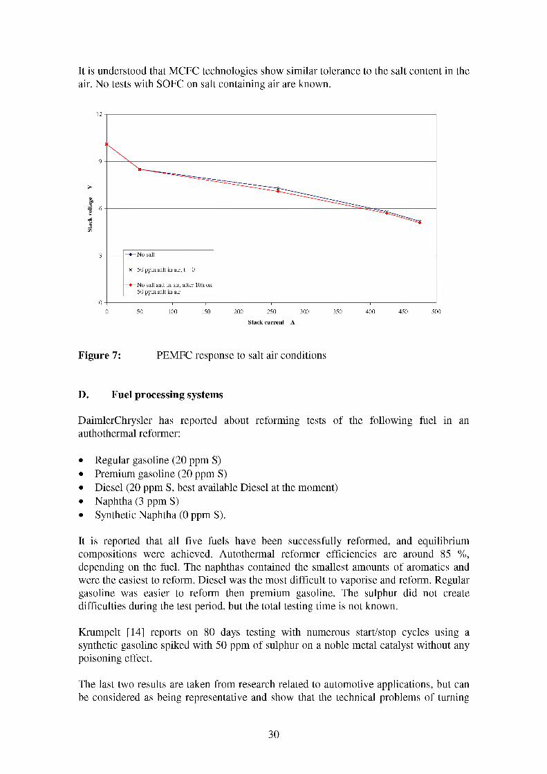
It is understood that MCFC technologies show similar tolerance to the salt content in the air. No tests with SOFC on salt containing air are known.
No salt
x 50 ppm salt in air, t = 0
No salt salt in air, after lOh on50 ppm salt in air
Stack current A
Figure 7: PEMFC response to salt air conditions
D. Fuel processing systems
DaimlerChrysler has reported about reforming tests of the following fuel in an authothermal reformer:
• Regular gasoline (20 ppm S)• Premium gasoline (20 ppm S)• Diesel (20 ppm S, best available Diesel at the moment)• Naphtha (3 ppm S)• Synthetic Naphtha (0 ppm S).
It is reported that all five fuels have been successfully reformed, and equilibrium compositions were achieved. Autothermal reformer efficiencies are around 85 %, depending on the fuel. The naphthas contained the smallest amounts of aromatics and were the easiest to reform. Diesel was the most difficult to vaporise and reform. Regular gasoline was easier to reform then premium gasoline. The sulphur did not create difficulties during the test period, but the total testing time is not known.
Kmmpelt [14] reports on 80 days testing with numerous start/stop cycles using a synthetic gasoline spiked with 50 ppm of sulphur on a noble metal catalyst without any poisoning effect.
The last two results are taken from research related to automotive applications, but can be considered as being representative and show that the technical problems of turning
30

liquid fuels into fuel cell compatible ones can be overcome. It has to be stressed, that poisoning effects depend heavily on the operation conditions (temperature, concentrations, etc) and materials used in the system. However, the economical viability remains to be demonstrated.
Fuel processing for high temperature fuel cell is considered to be less problematic than for low temperature fuel cells. High temperature fuel cells are much more resistant to impurities, like sulphur and carbon deposition.
E. Transient response
The transient behaviour of example PEMFC and MCFC based system is plotted in Figures 8 and 9.
100 % power--2.5
> 0.84
> 0.82
-- 0.525 % power
Time s
Figure 8: Load following time for a 2.85 MW MCFC system [15]
31

gasoline
time t/s
Figure 9: Load following of an authothermal reformer, demand change from 1kWe to 10 kWe
Reforming of the fuel might be the slowest process in the power plant, when an external reformer is used in the system. This is the case for PEMFCs not running on pure hydrogen; therefore it might be sufficient to investigate the dynamic behaviour of the reformer. The response to load changes of an authothermal reformer is plotted in Figure 9. This reformer was developed for car applications. A ramp from 1 kWe to 10 kWe was applied to the system. Air, steam and gasoline flows were increased at the same time. Thus the air to fuel and the steam to carbon ratio were kept constant. Hydrogen and carbon monoxide concentrations were measured online as well as the mass flow of the products. Time resolution of the data acquisition system was 2 seconds. Even without optimisation of the process, like adapting the air to fuel ratio, the response time was faster then 2 seconds.
E. Part load efficiency
Figure 10 shows the part load behaviour of different power plant technologies in the power range around 1 MWe. A fuel cell based system is compared to a conventional gas turbine based (note that the data for the fuel cell system is projected data whereas those for the conventional technologies can be supported with “experimental” data). Experience with high temperature fuel cells in the 100 kW range suggests that good performance and load following can be achieved. It can be seen that the stack efficiency is much higher than the net system efficiency. This suggests that there is potential to improve the part load efficiency of the power conditioning system and other auxiliaries.
As can be seen from Figure 10, fuel cells are expected to have a higher efficiency than other technologies, but even more importantly they promise a higher part load efficiency, leading to a better average efficiency over a typical operating period for
32

fluctuating loads. These results in reduced fuel consumption and is extending the operation range or reducing the required on board fuel storage. The higher average efficiency becomes more significant where ships are often operated in part load situation.
iLCELLSHlPSei
i COMMERCIAL GAS TURBINESENERATOREET- — ~j----
20 i:~—^ALUSON 501 :
POWER PLANT LOAD,%
Figure 10: Part load efficiency of different power plant technologies, fuel basedsystem’s efficiencies are projected [18]
Figure 11: Part load efficiency of a 100 kWe Westinghouse power plant
33

G. Start-up time
Current start-up times for SOFC based systems are of the order of 10h, it can be assumed that similar start-up time are required for MCFC systems. However, very little is known about the ultimate minimum possible start-up time of fuel cells. The prime reason for this is that high temperature fuel cells are still under development and it not justified at the present time to risk damage to a fuel cell system because of rapid startup.
Start-up times for PEMFC based systems might be faster, but no evidence has been found to determine whether it will be possible to achieve automotive targets of less then 2 minutes in the near future. However, the automotive industry seems to be confident that they can achieve this target. Similar targets are required for ship applications.
The main problem for PEMFC based systems is getting the fuel processor up to temperature. The upper working temperature of a fuel processor for a PEMFC system is typically around 500 C. As it is mainly build from metal it is difficult to transfer energy quickly to bring it up to operating temperature.
Systems working with stack integrated reforming, as may be the case for high temperature fuel cells, face an additional problem. Here the stack itself is made out of a combination of different materials (ceramic and metal based) and, if not exactly matched, the thermal expansion coefficients would introduce thermal tensions risking mechanical damage of the materials.
The correlation between start-up time and degradation is not well understood yet, but it is well known that rapid start-up and hot-cold cycles increase degradation.
H. Life time
It is believed that fuel cells could achieve life times of around 40 000 h. This is generally regarded as the minimum lifetime for economical viability. It is understood that SOFCs have the potential to achieve this figure whereas PEMFCs and MCFCs might struggle. MCFCs have to overcome electrolyte evaporation, high temperature corrosion and nickel diffusion through the electrolyte. PEMFC suffer from electrolyte poisoning of sulphur, CO and other contaminates. However, this would require a major overhaul of the ship's power plant every 5 years, including some out of service time in a shipyard and substantial work to exchange major parts of the bulky and heavy fuel cell system.
I. Power conditioning
All fuel cell based systems will require a power conditioning system if the fuel cell’s direct current output needs to be converted into AC.
Power conditioning is a well established technology for other applications, but the challenge for fuel cell applications, particularly those in marine applications, is to meet cost, weight, volume, etc targets.
34

J. Performance
Table 5 summarises the main characteristics of current major fuel cell based power plant demonstrations in stationary power generation. All listed units are first-of-its-kind units but substantial improvements can be expected before they reach the full mature stage. In particular, dramatic improvements in performance, specific power, power density as well as lifetime can be expected over the next decade.
Manufacturer SiemensWestinghouse Ballard MTU
Type SOFC atmospheric SOFC atmospheric SOFC-GT SOFC-GT PEM atmospheric MCFC atmospheric
SWP leaflet Fuel
EDB/ELSAM SWP leaflet Fuel Cell Cell Seminar SWP leaflet Fuel Cell
Remark demonstrator/NL Seminar 2000 2001 Seminar 2002
Max el Output kWe 100 250 300 1000 250 250
Max heat Output
Classification
kW
CHP CHP CHP CHP
Fuel natural gas natural gas natural gas natural gas natural gas natural gas
Efficiency
Installed Overall
% 47 > 45 > 55 ~ 60 40 > 47
Dimensions 3.6 x 2.8 x 8.6 3.4 x 2.6 x 11.1 3.6 x 3.6 x 11.7 4 x 11 x 17 2.4 x 2.4 x 6.1 3 x 2.5 x 9
Volume m3 86.7 98.1 151.6 748 35 67.5
spec Power kWe/m3 1.15 2.55 1.98 1.34 7.14 3.70
Weight kg 22400 27000 31000 12500 16000
spec Power kWe/kg 0.004464286 0.009259259 0.009677419 0.02 0.02
Degradation %/1000 h 0.25
Fuel Utilisation
Emissions
% 85 80 > 70
NOx ppm < 1 ppm
CO ppm < 1ppm
SOx ppm < 1ppm
dBA 60 (1 m)
Maintenance Annual Air Blower Inspection, On-
Inspection, On-Line Annual GT Inspection,
Desulfurizer Desulfurizer On-Line Desulfurizer
Table 5: Properties of different fuel cell technologies
Table 6 shows similar information to Table 5 for selected reciprocating engine based CHP plants.
Comparing both technologies shows that:
• The specific power and power density of reciprocating engines is about 10 times higher than that for fuel cell based systems
• Fuel cell systems have a much higher electrical efficiency• Fuel cell systems produce less noise• Fuel cell systems require less maintenance.
But is has to be stressed, that the engine based power plants are mature and commercial available systems, whereas fuels are in an early development stage, so that their potential for improvements is much higher.
35

Criteria Slow Speed Diesel
MediumSpeed Diesel
High Speed Diesel
Simple Cycle Gas Turbine
Fuel Heavy Fuel Oil Heavy Fuel Oil or MarineDiesel Oil
Marine Diesel Oil
Various but typicallyMarine Diesel Oil
Power output(kW)
1265 - 66000 3000 - 23280 300 - 4000 2300 - 50000
Thermalefficiency(approx.)
50 - 55% 40 - 50% 35 - 40% 35%
Volume (m3) 32 - 2150 20 - 645 1.5 - 19 6.7 - 188Power density(kW/m3)
39 - 31 150 - 36 200 - 210 343 - 266
Weight(tonnes)
41 - 2030 22 - 430 1 - 17 3 - 26
Specific Power (kW/tonne)
31 - 33 136 - 54 300 - 235 766 - 1923
Specific fuel consumption (approx.- g/kWh)
160 170 - 190 200 - 215 205 - 215
Specific costs£/kW
140 - 200 200 - 4000
Table 6: Properties of engine based CHP systems
K. Availability and reliability
Fuel cell based systems are expected to have a high availability as they incorporate only a few mechanical parts.
36

Availability PC25
3. Qtr. 97
1. Qtr. 97
3. Qtr. 96
1. Qtr. 96
3. Qtr. 95
1. Qtr. 95
3. Qtr. 94
1. Qtr. 94
3. Qtr. 93
0 10 20 30 40 50 60 70
Figure 12: Availability of a PC25 Fuel Cell
91.71100
0.86t92.51
192.63
= 95.;
9=194.18=□94.97
86 1.78
=99 67□ 96.24
80 90 100
Fuel cells are generally expected to degrade rather than fail. Figure 12 gives for illustration the availability of an ONSI PAFC PC 25. This example has been chosen, as it gives measured values of an existing plant over a long period of time. It can be expected that other fuel cell technologies will show similar availability and full mature products could achieve even higher availability. The average availability was around 88%; of particular interest are the three very low values occurring in the 3rd quarter of each year. This suggests a systematic problem to a reoccurring event during this moment in time.
L. Maintenance costs
Maintenance costs PC25 29/6/93 to 16/7/97
External causes, 1%
Customer supplied components
0%
•Rrocessieag^f%nti|atio^FuelsPyrs0=emSsm9
1% System / n%
Water Treatment System
35%Thermal Management
Systemtotal maintenance costs: 0.027 £/kWh 26%
Power Distribution System
2%Fuel Cell Stack
1%
Figure 13: Maintenance costs of a PC25 Fuel Cell
37

Figure 13 shows the break down of the maintenance cost of a PC25, again these are real data from operating fuel cell based power plant and can give indications of maintenance requirements for other fuel cell technologies. As can be seen from the figure, the stack (“power section system”) accounts only for 1% of the maintenance costs. The total maintenance costs are about 0.08 DM/kWhe (~ 0.027£/kWhe, expected to at 0.024 DM/kWhe by 2010). It can be expected that these costs can be further reduced for fully mature products.
3.4 Improvements in the near and medium future
US Office of Naval Research targets
The targets of US Office of Naval Research (ONR) advanced development programme to demonstrate a ship service fuel cell power generator module (SSFC) are summarised here again:
• Provide 2.5 MWe net electrical power at 450 VAC, 3 phase 60 Hz• Run on NATO F-76 fuel• Achieve minimum system efficiency of 40% at 50% of rated load• Achieve systems size and weight goals of 57 l/kWe and 18 kg/kWe (about the order
of stationary power generators)• Achieve estimated costs in production of $1500/kWe• Be developed using commercial or near-commercial technologies• Be highly reliable and maintainable• Be self-containing with respect to water balance and energy balance
US-DoE’s technical target for a 50 kWe fuel cell for the automotive industry is even tighter, but car propulsion systems contain much simpler heat recovery systems, electrical generators and controls; these sub systems are contributing substantially to the system weight.
Power density
ONSI achieved a weight reduction of 40 % and a volume reduction of 30 % by moving from one generation to the next of their fuel cell based 200 kWe PC25 power plants. Costs are still high, around 3000 $/kWe, 1000 $kWe are commonly believed as competitive in this power range. A production of around 250 units over almost 10 years has not lead to a competitive cost reduction. On the other hand, operation experience with over 250 units confirm the fuel cells potential for low maintenance costs and high reliability, if all auxiliary systems are properly chosen and integrated into the plant.
ONR’s targets for specific power, power density and specific costs will be the major challenges in the future. The target figures are in the order of those achievable by conventional stationary power plants of similar size today. Fuel cells will have to increase their power density by a factor of ten and cost reduction by a factor of 100 or more. Fuel cells for ship applications will use or depend on the progress made for fuel cells in other areas, as it is not expected that marine applications will substantially push the development.
38

Based on ONSI’s experience, it can be concluded that volume and weight reduction of 100 % for other less mature fuel cell systems looks to be possible in the sort to medium term. A volume and weight reduction by 10 appears to be a very challenging target.
Reliability
Reliability and maintainability has to be shown in long term tests and under commercial conditions, but confidence is growing that these targets could be achieved over the next 5 to 10 years. ONSI’s experience underline the low maintenance potential of fuel cells.
Marine fuel
Building fuel cell systems running on NATO F-76 fuel and achieving efficiencies between 40 and 50 % is believed to be achievable.
Summary
Each target seems to be achievable on its own, but the combination of all this targets contains the major challenge.
39

4 Fuel Cells vs Diesel engines and gas turbines
This section compares the major properties of fuel cells with those of diesel engines and gas turbines.
To be an attractive to the marine propulsion and ship service power market, fuel cell based systems will need to have characteristics that make them competitive with current and predicted future, conventional based prime movers. A series of comparisons can be made between conventional and fuel cell based prime mover systems, against the criteria established for prime mover performance assessment.
When comparing fuel cells against conventional technologies, it is important to bear in mind that the fuel cell system must be competitive with the dominant technology for a given market sector. Consequently, for those market sectors dominated by direct drive solutions, the performance of the fuel cell must be modified to account for the performance effect of the required electrical elements of the propulsion system (electrical motor and drive)5.
Where electric propulsion is the dominant solution, or has a significant share of the market sector, then it is safe to compare the fuel cell directly against the conventional prime mover. The modified performance due to the electrical components is offset by the proven (or indicated) increase in capability or functionality of the electrical propulsion system over the conventional one.
4.1 Thermal Efficiency and Fuel Consumption
Typical thermal efficiencies for various prime movers are shown below:Fuel to electrical Power Efficiency for Different Prime Movers "Hotel Load Scenario"
ACGT or CCGT + Alternator
Simple Cycle Gas" Alternator
High Speed Diesel + Alternate^
Medium Speed E Alternator
Low Speed Diesel + Alternated
30
GT rell r tel] 1 Iitor [______ i
G 1iter [______
i
------ 145 50 55
Fuel to electrical Power
Figure 14: Fuel to electrical Power for different prime movers “hotel load scenario”
5 The bars for “Low Temp Fuel Cell + Motor” and “High Temp Fuel Cell + Motor” (for all charts) include the system efficiencies for the electrical transmission, so as to convert the electrical output of a fuel cell into the mechanical output required.
40
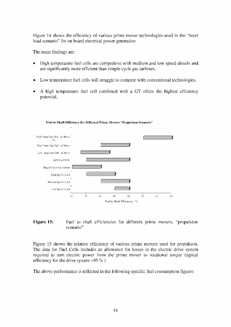
Figure 14 shows the efficiency of various prime mover technologies used in the “hotel load scenario” for on board electrical power generation.
The main findings are:
• High temperature fuel cells are competitive with medium and low speed diesels and are significantly more efficient than simple cycle gas turbines.
• Low temperature fuel cells will struggle to compete with conventional technologies.
• A high temperature fuel cell combined with a GT offers the highest efficiency potential.
Fuel to Shaft Efficiency for Different Prime Movers ,fPropulsion Scenario”
High Temp Fuel Cell + el. Motor + GT
High Temp Fuel Cell + el Motor
Low Temp Fuel Cell + el Motor
ACGT or CCGT
Simple Cycle Gas Turbine
High Speed Diesel
Medium Speed Diesel
Low Speed Diesel
-
r -f 1
i
c i
1 —1c l
i i
c i40 45 50 55
Fuel to Shaft Efficiency %
Figure 15: Fuel to shaft efficiencies for different prime movers, “propulsionscenario”
Figure 15 shows the relative efficiency of various prime movers used for propulsion. The data for Fuel Cells includes an allowance for losses in the electric drive system required to turn electric power from the prime mover to rotational torque (typical efficiency for the drive system ~95 % )
The above performance is reflected in the following specific fuel consumption figures:
41

High Temp Fuel Cell + el. Motor + GT
High Temp Fuel Cell + el Motor
Low Temp Fuel Cell + el Motor
ACGT or CCGT
Simple Cycle Gas Turbine
High Speed Diesel
Medium Speed Diesel
Low Speed Diesel
0
f i
f 1a
a
oi==io
n i i i i50 100 150 200 250
Specific Fuel Consumption (g/kWh)
Figure 16: Specific fuel consumption for different prime movers
This figure indicates the following key points:
• The estimates of the fuel consumption for high temperature fuel cells are considerably better than those for the conventional technologies. Additionally, the incorporation of an electrical motor and drive into the system, whilst reducing the fuel efficiency, still leaves the high temperature fuel cell competitive against the best of the direct drive conventional systems.
• The low temperature fuel cells only really compete with high speed diesels and simple cycle gas turbines, these are typically selected in applications where space and weight constraints are the primary design drivers before fuel consumption.
4.2 Part load efficiency / specific fuel consumption vs load
Whilst, as mentioned in previous sections of this report, many vessels experience relatively constant propulsion and ship service loads (i.e. Bulk Carriers), others (i.e. Cruise Liners) can experience significant load variation. In the latter applications the part load performance characteristics can perhaps be as significant as the performance at the design point.
42

Low Temperature Fuel Cell Part Load Performance
Figure 17 shows the diesel consumption for two different marine gas turbines (Allison 501-K34 and LM25000), a next generation gas turbine (ICR: inter cooled, recuperated) as well as for a PEMFC.
Fuel Consumption vs load
—Allison 501-K34- LM2500- -ICR- -PEMFC
Figure 17: Fuel consumption vs load for different technologies [24]
Key points:
• The specific fuel consumption for conventional gas turbines is generally constant above 80 % of nominal load, but increases sharply for loads less than 50 %.
• The PEMFC’s fuel consumption is less than for the gas turbines and constant down to 20 % of load.
• The next generation gas turbine shows similar part load fuel consumption behaviour to the fuel cell, but at a slightly higher level.
High Temperature Fuel Cell Part Load Performance
Figure 18 shows the part load efficiency of the 100 kWe SOFC SiemensWestinghouse demonstrator in the Netherlands. The electrical efficiency of the stack is fairly constant with load, but the total net efficiency drops sharply with decreasing load. This is mainly because there is not enough heat available from the exhaust to pre heat the incoming process air. As such it is necessary to pre heat the air with an auxiliary electrical heater, significantly impairing the efficiency.
43

70
electrical stack efficiency
net electrical systems efficiency
Siemens'Westinghouse 100 kW demonstrator in the Netherlands
0 -I-------------------------------------- 1-------------------------------------- 1-------------------------------------- 1-------------------------------------- 1-------------------------------------- 1--------------------------------------
0 20 40 60 80 100 120
Load %
Figure 18: Part load efficiency of the 100 kWe SiemensWestinghousedemonstrator in the Netherlands [10]
Figure 19 show the modelled efficiency for a "mature" power plant in which a SOFC is combined with a gas turbine. The total net efficiency of the plant is around 65 %, some 20 % more that for the 100 kWe system in Figure 18. But more importantly, the figure suggests that the efficiency is fairly constant over a wide range of load in contrast with the 100 kWe plant. However, the results from Figure 19 are modelled results only and require experimental confirmation.
1400.0 0.700
Efficiency (to1200.0 0.600electricity)
Total power1000.0 0.500
800.0 0.400
600.0 0.300Turbogenerator at 110% speed
Turbo Stack power
400.0 0.200
200.0 0.100
0.000100.0 120.0 140.0
jjo<u2too.
% Plant power level
Figure 19: Modelled efficiency for 1.2 MWe SOFC-GT power plant [26]
44
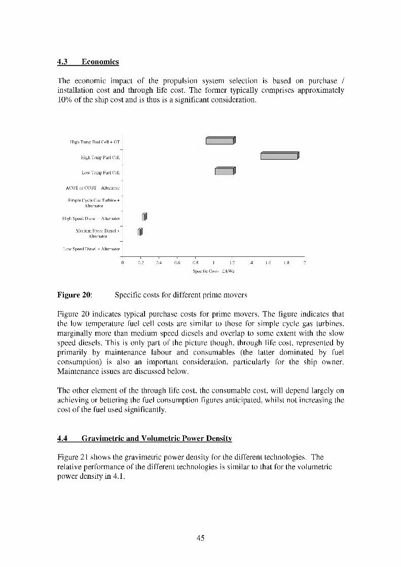
4.3 Economics
The economic impact of the propulsion system selection is based on purchase / installation cost and through life cost. The former typically comprises approximately 10% of the ship cost and is thus is a significant consideration.
High Temp Fuel Cell + GT
High Temp Fuel Cell
Low Temp Fuel Cell
^=1
r- - - - - - \a
ACGT or CCGT + Alternator
Simple Cycle Gas Turbine + Alternator
High Speed Diesel + Alternator
Medium Speed Diesel + Alternator
Low Speed Diesel + Alternator
0.2 0.4 0.6 0.8 1 1.2
Specific Costs f/kWe
1.4 1.6
Figure 20: Specific costs for different prime movers
Figure 20 indicates typical purchase costs for prime movers. The figure indicates that the low temperature fuel cell costs are similar to those for simple cycle gas turbines, marginally more than medium speed diesels and overlap to some extent with the slow speed diesels. This is only part of the picture though, through life cost, represented by primarily by maintenance labour and consumables (the latter dominated by fuel consumption) is also an important consideration, particularly for the ship owner. Maintenance issues are discussed below.
The other element of the through life cost, the consumable cost, will depend largely on achieving or bettering the fuel consumption figures anticipated, whilst not increasing the cost of the fuel used significantly.
4.4 Gravimetric and Volumetric Power Density
Figure 21 shows the gravimetric power density for the different technologies. The relative performance of the different technologies is similar to that for the volumetric power density in 4.1.
45

MCFC 9
MCFC achieved
SOFC tubular projected
SOFC tubular achieved [0
SOFC planar projected
PMFC projected
PMFC achieved 0 ACGT or CCGT
Simple Cycle Gas Turbine
Flight Speed Diesel
Medium Speed Diesel
Low Speed Diesel 0
0.2 0.4 0.6 0.8 1 1.2
Gravimetric Power Density kWe/kg
1.4
Figure 21: Gravimetric power density for different prime movers
MCFC
MCFC achieved (0
SOFC tubular projected
SOFC tubular achieved 0 SOFC planar projected
PMFC projected
PMFC achieved (0
ACGT or CCGT
Simple Cycle Gas Turbine
Flight Speed Diesel
Medium Speed Diesel
Low Speed Diesel
0
J
3r- - - - - t
c
20
I—If t
I | power density for GTs can be as high as 4000
^3
40 60 80 100 120 140 160 180 200
Volumetric Power Density kWe /m3
Figure 22: Volumetric power density for different prime movers
Figure 22 compares the typical volumetric power density of different marine prime movers. Note that the figures given for conventional prime movers represent typical figures and that there is a wide spread for each category (see appendix B). The
46

conventional technologies use marine fuels (either HFO: heavy fuel oil or MDO: marine diesel oil) as fuel, but do not contain an alternator.
The figures given for fuel cells are typical figures for stationary fuel cell based power generation demonstration. This approach was chosen because more development effort has gone into this area than for marine applications, hence more experience and reliable data is available. All fuel cells are assumed to be running on natural gas. Switching to liquid fuels would increase volume and weight of the plant through the need to provide suitable fuel processing equipment.
It should also be noted that fuel cell systems contain DC/AC converters for integration into an AC electrical network and this contributes to the weight and volume of the plant. However, if the vessel employed a DC propulsion bus this equipment could be simplified significantly saving both volume and weight.
The figures given for each fuel cell technology (labelled “achieved”) are existing demonstration plants, so a very high degree of confidence can be placed on them. As they are demonstration plants, savings in volume and weight can be expected when moving towards a mature product. However this volumetric power density is still 4 to 30 times less than that of conventional technologies.
The othe figure for fuel cell technologies are predictions of the volumetric power density for different fuel technologies. They show that:
• PEMFCs and SOFCs can achieve similar performance to diesel engines but are unlikely to reach the gas turbine’s performance.
• MCFCs and PAFCs cannot compete with diesel engines in terms of volumetric power density.
In summary, fuel cell based systems generally perform poorly in terms of weight and space. They are only competitive with slow speed diesels and the larger medium speed diesels. Significantly, the top end of the high and medium speed diesel and the simple cycle gas turbine markets show performance significantly in excess of that offered by the fuel cell options.
4.5 Maintenance
It is anticipated that a fuel cell based system will offer reduced maintenance over an equivalent conventional system. With the exception of the fuel system, the supporting auxiliaries will be no more complicated and the lack of moving parts in the fuel cell itself should result in the system requiring considerably less maintenance than a conventional internal combustion engine.
Additional, the “clean” nature of the fuel cell system, i.e. the lack of moving parts and hence lubricating oil, suggest a lower ship husbandry / cleaning burden. The combination of these factors suggest a greatly reduced maintenance burden, representing
47

potential savings in terms of reduced consumable use and reduced manpower requirements.
4.6 Emissions
This section discusses the comparative CO2, NOx and SOx emissions from different marine prime movers.
4.6.1 NOx emissions
NOx can be formed from nitrogen out of the fuel and by high temperature reactions with nitrogen present in the intake air. Typical low cost marine fuels such as HFO (heavy fuel oil) contain much more nitrogen than distilled fuel or natural gas. Combustion based processes will start generating NOx from air borne nitrogen above 1000 °C. Studies conducted by the marine International Council for Internal Combustion Engines (CIMAC) suggest that air borne nitrogen dominates the NOx formation process.
The formation of NOx is dependent on the combustion temperature and duration. Temperatures tend to remain fairly constant across diesel engine designs, however as combustion times are directly related to speed of rotation, slower engine rotation, leads to a greater formation of NOx.
NOx emissions from different technologies
high speed medium slow speed gas turbine, advanced low high highdiesel, 40% speed diesel diesel, 45% 35% gas turbine, temperature temperature temperature
43% FC. 40% FC. 45% FC + GT.65%
Figure 23: Typical NOx emission from different prime movers [22]
NOx emission from fuel cells will be lower than that from conventional prime movers, partly as they have to use higher quality fuels but primarily as they operate at temperatures where negligible amounts of NOx are generated. Temperature and
48

concentration of air and fuel in the reaction zone are more uniform in a fuel cell than in a combustor, and no hot spots occur.
4.6.2 SOx emissions
Consideration of the SOx emissions performance of the different technologies clearly shows the advantage of fuel cells over conventional technologies. However, this is somewhat mis-leading as it is primarily a consequence of the need to operate fuel cells on low-sulphur fuels in order to ensure that they are not subjected to harmful sulphur contamination. The price for this is incurred either directly through the increase in cost of ultra low sulphur fuel or indirectly through the installation of sulphur elimination plants on board which will increase the installed costs, volume, weight etc of the fuel cell system.
Reduced sulphur emissions from conventional technologies can be achieved in the same way at similar costs (by using cleaner fuels), but conventional technologies do not require low sulphur fuels in order to operate and thus have a significant logistic advantage. In fact some of them use sulphur as internal lubricant, so low sulphur fuels my cause damage to the engine, and suitable replacement additives may be necessary in the future.
S02 Emissions of different prime movers
marine fuels
41 MJ/kgdifferent S concentrations (4, 3, 1, 0.001%) 95% reformer efficiency for PCs
high speed medium slow speed gas turbine, advanced gas low high highdiesel, 40% speed diesel diesel, 45% 35% turbine, 43% temperature temperature temperature
PC, 40% PC, 45% PC + GT,65%
Figure 24: Typical SOx emissions
4.6.3 CO2 emissions
CO2 emissions depend only on the fuel type and the efficiency of the prime mover. Fuel cells have a slightly higher efficiency than diesel engines when run on natural gas and a significantly higher efficiency when run on hydrogen. However, when fuel cells are run on liquid marine fuels, one has to take the reformer efficiency into account.
Typical reformer efficiencies are above 95%, but this additional penalty means that the lower efficiency fuel cell systems, such as PEMs, will struggle to achieve lower CO2
49

emissions than those currently produced by conventional technologies in a propulsion application.
However, when considering onboard power generation, the figures for conventional technologies do not take into account the generator efficiency, typically around 95 %, and thus PEMs coul be more competitive in this application.
Both for propulsion and power generation, high temperature fuel cells achieve slightly lower CO2, and significantly lower emissions, particularly in hybrid configurations combined with a gas turbine, compared with conventional technologies.
C02 Emissions of different prime movers
1000
900
800
high speed slow speed gas turbine. advanced gas low high highdiesel, 40% diesel, 45% 35% turbine, 43% temperature temperature temperature FC
FC. 40% FC. 45% + GT. 65%
Figure 25: Typical CO2 emissions for different marine prime movers
50

4.7 NoiseTypical noise levels
Figure 26: Typical noise levels generated by different sources [23]
The noise level in a diesel engine room is almost as high as that found near an aircraft engine and resultant noise in the cabin compares to that found in a typical department store.
In contrast the noise in a cabin of a fuel cell powered ship is expected to be similar to that found in an office. This lower noise level could increase the comfort on a ship or could offer the possibility to build extra cabins close to the engine room. Note, that the noise scale is logarithmic, so a difference of 10 dB (A), the difference between a near by aircraft engine and a diesel engine room, make a significant difference to the human ear.
4.8 Summary
In terms of overall efficiency and the resultant fuel consumption, fuel cells offer advantages over conventional prime movers with the exception of slow speed diesels and combined cycle gas turbines. Theoretically, with development, they offer further scope for improving efficiency to a level that surpasses any heat engine prime mover. Part load efficiency is also improved over gas turbine systems and generally comparable to diesel engines.
Consequently they offer potential benefits for those applications where fuel consumption is a key requirement. However these benefits may be offset by increased fuel costs if clean or reformed fuels are required.
Fuel cell power density is equivalent to slow or medium speed diesels and can not currently compete with gas turbines or the better high speed diesels. Consequently fuel cells should not be considered as the sole power source for applications requiring power density as the key design driver.
51

It would be unfair to make too much of a comparison of the current purchase costs of fuel cells compared to conventional technologies. It is anticipated that given investment and potential markets, the costs of fuel cell production will be reduced significantly below current levels. From current comparisons, this is likely to make them a competitive alternative. Additionally the predicted reduction in maintenance will further enhance their attractiveness.
The reduced emissions from fuel cells make them extremely attractive for vessels operating in environmentally sensitive areas. It will also improve their financial viability if emissions legislation continues to tighten as predicted.
52

5 Applicability Of Fuel Cells To Propulsion Systems
This section of the report presents first the applicability of fuel cells to propulsion systems for a number of generic vessels types. It also summarises the results of two studies, which investigated the technologies potential as applied to specific vessels.
5.1 Generic Vessel Types
5.1.1 Intercontinental Cargo Ships
As described in appendix A, the principal requirements for large merchant ships are:
• High installed power• Excellent fuel economy• Sustained reliability• Simple propulsion system• Low maintenance whilst at sea
The powers required for these ships are well beyond the levels of current prototype fuel cells. An estimated 40 - 100 times power increase is required before the power requirements for bulk cargo carriage are reached.
The benefits of electric propulsion systems have not yet convinced current operators of large cargo vessels to move away from conventional mechanical drive systems. However, extrapolated fuel consumption figures suggest that high temperature fuel cells may offer a benefit in terms of enhanced efficiency - the prime requirement for these propulsion systems.
This is supported by the thermal efficiencies demonstrated by fuel cells (in the order of 40 - 50 %, competitive with that for a slow speed diesel (>50%), or better if a high temperature fuel cell is combined with a gas turbine (thermal efficiency may be increased to 60 -70%).
Whilst weight will not be a significant issue for ships of this sort of size, increased volume represents a reduction in cargo which may, or may not be economically significant. Even without consideration of the additional electrical equipment required (power inverters, motors, motor drives) and any fuel reformation system, the volumetric power density of a high temperature fuel cell is no better than a slow speed diesel [29].
The simple, single shaft propulsion system used for these large vessels places a high emphasis on reliability. It is expected that the lack of moving parts in a fuel cell will offer improved reliability over conventional technologies. In addition, the steady operation of these vessels and their propulsion systems is beneficial to preventing cyclic thermal loading and fatigue of a high temperature fuel. However, fuel cell system reliability (and availability) are as yet, not demonstrated over a significant period of time.
53

Slow speed diesels generally show poor performance, in terms of NOX and SOX emissions, when compared to other engines. Further tightening of environmental legislation may have a critical impact on the economic performance of the slow speed diesel. Of particular interest is the possibility of tightened NOX legislation requiring the adoption of engine technology, such as exhaust gas clean up, and the impact of SOX legislation requiring reduced sulphur content in marine fuels.
The former scenario has a significant impact on the running cost of the engine. It is estimated that switching from on-engine NOX treatment to off-engine treatment of the exhaust is likely to be required if NOx targets of less than 10 g/kWh (for a slow speed engine) are required. This may represent an increase of up to 40% in the running cost of the engine [17].
Low sulphur fuel is required to meet future tightening of SOX limits or for access to SOX emission control areas. The cost differential of HFO suitable for operating in a SOX emission control area against that typically carried by large cargo vessels is estimated at 10 - 20 £/tonne [28], equivalent to a 10 - 20% increase in fuel cost [17]. Such an increase in fuel cost may well upset the economics of the slow speed propulsion system. It will certainly act in favour of the fuel cell, by offsetting the costs of any fuel reformation or high grade fuel required. As yet no comparison in cost per tonne is available for a fuel cell compatible marine fuel oil and HFO. However, the increased cost of low sulphur HFO will need to be taken into account for future trends.
A special case in the large merchant ship category is the Liquefied Natural Gas (LNG) Carrier, or Liquefied Petroleum Gas (LPG) Carrier. These vessels carry natural or petroleum gas in liquid form in special cargo tanks. The pressurised, cold nature of the liquid gas leads to “boil off” of the cargo, a feature that is currently used to feed steam generators for propulsion turbines or dual fuel internal combustion engines. Such a boil off fuel (typically alkane based) would be ideal for fuel cells propulsion systems. However this approach needs to be assessed on the basis of relative costs of cargo and fuel and the ability to power the vessel during unloaded journeys, i.e. with no cargo.
Without demonstration of long term reliability, and improved fuel consumption at the sorts of loads required for large ships, it is likely that a relatively conservative and financially driven sector of the marine market such as this one will resist a new or novel propulsion system.
5.1.2 Coastal Cargo vessel
Coastal cargo ships typically require:
• Economic operation• Flexible, readily available propulsion system• Simple system• Rapid throttle response
54

A power increase in the order of 6 times over that typically demonstrated by current fuel cells is required before the power requirements for local cargo carriage are reached.
A shift towards electric propulsion may offer some benefits to typical coastal vessels. These include the possibility of reducing the installed power by combining manoeuvring and propulsion loads, increased efficiency of propulsion machinery at part load and a reduction in running hours on engines. However, the perceived marginal benefits and increased purchase cost of the required electric equipment seems to have deterred operators from investigating this issue in any great depth.
Extrapolated fuel consumption figures suggest that high temperature fuel cells offer significant benefits in terms of enhanced efficiency - one of the prime requirements for these propulsion systems. Coupled with the flexibility of an electric propulsion train and the combination of the propulsion, manoeuvring and hotel loads, fuel cells are potentially an attractive proposition for coastal cargo vessels.
This is supported by the thermal efficiencies demonstrated by fuel cells (in the order of 40 - 50 %), competitive with that for a medium speed diesel (<50%), or if a high temperature fuel cell is combined with a gas turbine (thermal efficiency may be increased to 60 -70% ). The relatively small size of coastal / inland vessels and the high premium on cargo capacity suggest that steam regeneration systems will not be attractive. Without consideration of the additional electrical equipment required (power inverters, motors, motor drives) and any fuel reformation system, the volumetric power density of a high temperature fuel cell is no better than a medium speed diesel.
A number of these types of vessels operate on fairly standard routings over short distances. In such situations, it may be feasible to construct fuel reformation plants at given ports, so that the vessels embark a suitable fuel for a fuel cell system. This may be a more compatible hydrocarbon (such as methanol or low sulphur diesel) or some other hydrogen carrier. This allows easier implementation of fuel cell technology with a better confidence that the predicted performance can be achieved.
The reliability of fuel cell systems on the sort of scale required for coastal / inland shipping has yet to be demonstrated. It is expected that the lack of moving parts should offer good reliability. Though the impact on high temperature fuel cells of cyclic thermal loading and fatigue due to fluctuating manoeuvring loads will need to be assessed.
Reliability (and availability) will need further demonstration at a power level equivalent to the sorts of powers required for coastal cargo vessels, to allow increased confidence. If reliability is sufficiently demonstrated then it makes fuel cells even more attractive. It is unlikely that a financially driven sector of the marine market such as this one will adopt a new or novel propulsion system, without this further confidence.
Medium speed diesels generally show adequate performance, in terms of NOX and SOX emissions, when compared to other engines. However, as before, further tightening of environmental legislation may have a critical impact on the economic performance of the HFO fuelled medium speed diesel. The impact of SOX legislation requiring
55

desulphurisation of HFO will increase the cost of the fuel used by these diesels, thus reducing the economic benefits of HFO fuelled medium speed engines.
The cost differential of HFO suitable for operating in a SOX emission control area against that typically carried by cargo vessels is estimated at 10 - 20 £/tonne [28], equivalent to a 10 - 20% increase in fuel cost [17]. Such an increase in fuel cost will alter the economics of the HFO fuelled medium speed propulsion system. This will act in favour of adopting MDO for medium speed systems, but also adopting the fuel cell, by offsetting the costs of any fuel reformation required.
Tightening of NOX limits has a significant impact on the running cost of the engine, whether it is fuelled by MDO or HFO. NOx formation is driven by the combustion process, rather than the fuel type (though nitrogen contained in the fuel will have a minor impact). It is estimated that switching from on engine NOx treatment to off engine treatment of the exhaust is likely to be required if NOX targets of less than 6 g/kWh (for a medium speed engine) are required. This may represent an increase of up to 40% in the running cost of the engine [17].
The low noise / vibration and minimal smoke and emissions characteristics of fuel cells will offer a less obtrusive presence. This is beneficial to vessels operating in coastal or inland waterways as they are particularly subject to public scrutiny.
5.1.3 Passenger Cruise Ship
In general, cruise ships require:
• Flexibility in the propulsion and power generation machinery• Reliability• Enhanced passenger comfort and improved on board environment• Economic operation
The power requirements for a large cruise liner are typically some 100 times the levels of power currently available from prototype fuel cell systems. Even the smaller cruise vessels are likely to require somewhere in the order of 20 - 50 times more power than is currently available.
The benefits of moving to electric propulsion are currently being explored and adopted. This is due to the benefits offered by the ability to combine the delivery of the hotel, manoeuvring and propulsion loads, the possibility of reduced installed power, the improved system part load performance and the reduction in running hours accumulated on the engines. It is expected that the trend will continue but may not completely dominate the market. The move towards electric propulsion promotes the utilisation of fuel cells. Cruise line operators are likely to look for an immediate economic saving, but this may not be the key driver. In the past, propulsion equipment or systems perceived as expensive have been selected for the purposes of public image, through life cost and environmental performance.
56

Extrapolated fuel consumption figures suggest that high temperature fuel cells may offer a significant benefit in terms of enhanced efficiency over medium speed diesels, advanced cycle gas turbines and certainly over simple cycle gas turbines.
This is supported by the thermal efficiencies demonstrated by fuel cells (in the order of 40 - 50 % or 60 - 70% when combined with a gas turbine), competitive with that for a medium speed diesel (<50%), advanced cycle gas turbine (40 - 60%) and better than simple cycle gas turbines (30 - 40%). Similar technology has been adopted for gas turbine based systems for large cruise liners.
The reliability of fuel cell systems on the sort of scale required for cruise liners has yet to be demonstrated. It is expected that the lack of moving parts will offer good reliability. The impact of fluctuating manoeuvring, propulsion and hotel loads on cyclic thermal loading and fatigue of a high temperature fuel cell system will also need to be evaluated. The flexibility of assembling the fuel cell stacks allows the system to be tailored to provide frequent loads at efficient operating point and also to minimise the requirement to start up and shut down stacks. This offers benefits for system reliability.
The requirement for cruise liners to be able to visit beauty spots and the tightening environmental legislation governing emissions around these areas has driven a number of operators to consider the use of low emissions gas turbines (despite their poor efficiency compared to diesels). From this point of view, fuel cells offer a significant benefit of excellent environmental performance, in terms of NOX, SOX, and smoke with no impact on performance. Such a benefit may well outweigh any economic penalty incurred from increased size or initial outlay.
The low noise and vibration features of fuel cells are desirable for cruise liners as passenger comfort is at a premium. Current vessel designers often have to invest significant amounts of time and money into minimising the noise and vibrations experienced, particularly in cabins and other quiet areas. Starting from a low noise and vibration propulsion system should significantly reduce this investment.
The crucial economic balance for cruise liners is the initial outlay on the vessel, the through life running costs and the attractiveness to passengers (i.e. how much they can be charged). Fuel cell features that improve passenger comfort (low noise and vibration) public image (good environmental performance) and prestige (cutting edge technology) will all serve to improve the latter factor.
5.1.4 Short Haul / Rapid Turn Around Ferry
Two categories of short haul ferries have been discussed:
1 Conventional slow speed ferries2 Fast Ferries
The requirements for the propulsion systems for conventional ferries are:
• Economic operation
57

• Reliability• Simplicity• Flexibility and system availability• Power density
The benefits of moving to electric propulsion are being explored but have not yet been widely adopted. There are potential benefits due to high hotel and manoeuvring loads that can be combined with the propulsion system. The higher cost and volume of electrical machinery will be important in the balance of initial outlay, through life cost and revenue earning potential.
Extrapolated fuel consumption figures suggest that high temperature fuel cells may offer a significant benefit in terms of enhanced efficiency over the medium speed diesels typically used for conventional ferries.
The case for adopting fuel cells for conventional ferry use hinges on the potential fuel and maintenance benefits of the fuel cells themselves and the increased installation flexibility offered by an electric propulsion system. The ability to install fuel cells into a wide variety of spaces, with reduced concerns for overhead height for the compartment, may offer improved vehicle loading and carriage. This must be weighed against the predicted increase in up front cost of an electrical propulsion system and any penalty to revenue earning capability due to the increased volume associated with the additional propulsion machinery.
Demonstration of the reliability of fuel cell systems is critical to their viability for ferry propulsion. Whilst ferry voyages are typically very short, they demonstrate a high utility, as this is directly linked to their revenue earning capability. In addition to this, ferry operators are continuously searching for reductions in turn around time. Consequently time along side for the vessel is minimised. It is expected that the lack of moving parts should offer good reliability. However, the impact of the large load fluctuations, particularly for manoeuvring, on cyclic thermal loading and fatigue of a high temperature fuel will need to be evaluated.
The operating regime of ferries, typically in coastal / territorial waters for the majority of their voyage, makes them vulnerable to tightening state legislated limits for emissions. Additionally ferries, like other vessels operating close to land, need to maintain a “clean” image. One of the worst aspects from this point of view is smoke emission from funnels. Consequently, fuel cells can offer significant benefits due to excellent environmental performance, in terms of NOx, SOx, and smoke with no impact on performance.
The cost differential of HFO suitable for operating in a SOx emission control area against that typically carried by cargo vessels is estimated at 10 - 20 £/tonne [28], equivalent to a 10 - 20% increase in fuel cost [28]. Such an increase in fuel cost will alter the economics of the HFO fuelled medium speed propulsion system. This will act in favour of adopting MDO for medium speed systems, but also adopting the fuel cell, by offsetting the costs of any fuel reformation required.
58

Tightening of NOx limits has a significant impact on the running cost of the engine, whether it is fuelled by MDO or HFO. It is estimated that switching from on engine NOx treatment to off engine treatment of the exhaust is likely to be required if NOx targets of less than 6 g/kWh (for a medium speed engine) are required. This may represent an increase of up to 40% in the running cost of the engine [17].
The requirements for Fast Ferries are:
• Power density• Economic operation• Reliability and propulsion system availability
Current evidence from the market place suggests that power density, in terms of weight, is the key driver, often at the expense of fuel consumption and maintainability. Reliability / redundancy of the system appears to be the second most important factor in the system design. The situation is not quite as straightforward as that. The economic equation for fast ferries is based on increased revenue due to faster crossings, against increased cost of high performance engines and increased fuel consumption. The nature of the vessel operations, at full power for the majority of the time at sea, and the criticality of vessel displacement (and hence equipment weight) mean that electric propulsion is considered unattractive due to increased system weight for little or no performance benefit.
5.1.5 Research & survey vessel
Research ships are perceived to require:
• Highly flexible propulsion systems• Adaptability to suit the ever changing vessel needs• Low air and structure borne noise• Low vibration levels
The power requirements of research vessels are low compared with many of the vessels discussed previously. Consequently the current prototype fuel cells are much closer, in terms of output, to the power plants used onboard research ships.
Electric propulsion has been widely adopted and the benefits offered are well understood and acknowledged. Adoption of electric propulsion or conventional propulsion is typically evaluated on a case by case basis. If fuel cells compete with the fuel economy, flexibility and reliability of medium and high-speed diesels then they are viable.
Cost tends to be less of a design driver than flexibility, redundancy and reliability. However when the desired system performance can be achieved in a number of ways, the choice between them is likely to be an economic one. Whilst a good share of this market sector has been met by electric propulsion systems, the convention propulsion train using medium speed diesels still plays a significant role. Traditional mechanical propulsion systems are generally viewed as cheaper options, in terms of up front cost,
59

than electric propulsion systems. Consequently where the enhanced low power performance of an electrical system is not required, a mechanical system is selected. If fuel cells realise the through life savings predicted (in terms of fuel and reduced maintenance) then the market may change.
Efficiency
Predicted fuel consumption figures indicate that high temperature fuel cells offer fuel cell efficiencies that are competitive with medium speed diesels and probably better than high speed diesels, reflected by thermal efficiencies of 40 - 50 %, compared to the best medium speed diesels at about 50%. Fuel cell system efficiency can be significantly improved if the heat generated by the fuel cell system is recovered as steam and used for power generation or vessel heating. This is not likely to be a suitable option, due to the space requirement for the associated auxiliary equipment.
Performance
The flexibility and adaptability requirements are really delivered by the propulsion / power generation system selected. In the case of electric propulsion, it is predicted that fuel cells will provide the required response times and part load efficiency profiles required. The flexibility of assembling the fuel cell stacks allows the system to be tailored to provide frequent loads at an efficient operating point and also to minimise the requirement to start up and shut down stacks. This offers benefits for system reliability.
The investment required to undertake significant research activities underlines the importance of having demonstrated reliable equipment. It is expected that the lack of moving parts should offer good reliability. However, the impact of the large load fluctuations, particularly for manoeuvring / positioning and equipment (typically sonar) operations on cyclic thermal loading and fatigue of a high temperature fuel will need to be evaluated.
The lack of moving parts means that noise emissions are expected to be extremely low in comparison to rotating machinery. This has major benefits for surveying with sonar, or other acoustic based operations. Currently significant sums are invested in reducing the noise emissions of some research vessels to improve the acoustic surveying capability.
Emissions
A considerable amount of research is undertaken in support of the offshore industry. One of the key areas is the North Sea, a potential SOx emission control area. The required low fuel sulphur content for operation in these areas is generally achieved by MDO. However increasing legislation to protect environmentally sensitive areas such as the North Sea make fuel cell an increasingly attractive proposition.
5.1.6 Offshore Support & Specialist Applications vessel
The hugely varying requirements of offshore support ships may be summarised as:
60

ReliabilityFlexibility in the propulsion system Adaptability to suit varying work load Sustained safe operation
Electric propulsion has been widely adopted and the benefits offered are well understood and acknowledged. Adoption of electric propulsion or conventional propulsion is typically evaluated on a case by case basis. If fuel cells compete with the fuel economy, flexibility and reliability of medium and high speed diesels then they are viable.
Cost tends to be less of a design driver than reliability, redundancy and flexibility. However when the desired system performance can be achieved in a number of ways, the choice between them is likely to be an economic one.
Efficiency
Predicted fuel consumption figures indicate that high temperature fuel cells offer fuel cell efficiencies that are competitive with medium speed diesels and probably better than high speed diesels, reflected by thermal efficiencies of 40 - 50 %, compared to the best medium speed diesels at about 50%. Fuel cell system efficiency can be significantly improved if the heat generated by the fuel cell system is recovered as steam and used for power generation or vessel heating. The space requirement for the associated auxiliary equipment means that this is not likely to be a suitable option.
Performance
The flexibility and adaptability requirements are really delivered by the propulsion / power generation system selected. In the case of electric propulsion, it is predicted that fuel cells will provide the required response times and part load efficiency profiles required.
The safety criticality and cost involved in most offshore work dictates the requirement for reliable equipment. It is expected that the lack of moving parts should offer good reliability. However, the impact of the large load fluctuations, particularly for manoeuvring / positioning and equipment (winches, derricks, diver life support systems etc.) operations on cyclic thermal loading and fatigue of a high temperature fuel will need to be evaluated.
Emissions
One of the key areas for European offshore operations is the North Sea, a potential SOx emission control area. The required low sulphur content for operation in these areas is generally achieved by MDO. However increasing legislation to protect environmentally sensitive areas such as the North Sea make fuel cell an increasingly attractive proposition.
61

5.1.7 Leisure Craft
Leisure boats have quite unique propulsion system requirements:
• Very high power density in prime movers• Reliability• Sustained periods of no use• Safe operation
The physical dimensions of leisure craft and the typical emphasis on passenger / owner comfort and luxury, mean that despite image dictating a powerful propulsion system, little space is usually available for it.Consequently power density becomes a crucial requirement for the system, often at the expense of fuel consumption and maintainability. Reliability of the system appears to be the second most important factor in the system design. The nature of the vessel operations, with widely fluctuating loads for manoeuvring, cruising and high-speed transit, mean that electric propulsion may be operationally attractive. However operational and image considerations take priority over economic argument for these types of vessels. Indeed as a status symbol cost is generally not a problem.
5.1.8 Tourist Craft
Tourist craft require from the propulsion system:
• Economic operation• Good reliability• High power density• Low noise, emissions and vibrations to structure and environment
The physical dimensions of tourist craft, being quite small, dictate that power density is one of the key design drivers. Where possible this must be achieved without excessive detriment to system efficiency and maintainability. Good reliability is also required from the system with the flexibility and response time required to meet a fluctuating power requirement. The potential benefits of moving to electric propulsion have been explored, in paper studies, some of which have been fuel cell specific. Power density is one of the critical issues due to minimal space availability and electric systems are not expected to compete with high speed diesels and gas turbines in this respect. However the good fuel economy and low gaseous / smoke emissions make electric systems and fuel cells a potential power source. Public perception is important and a “clean” image assists in this. Tourist craft operate in coastal / inland waters and are subject to both public scrutiny and state legislation. Often this can include areas of special beauty especially tight environmental requirements. Such applications make fuel cell systems extremely attractive.
62

Summary
Key performance criteria need to be assessed on a case by case basis and the design drivers derived. These design drivers need to be compared to the beneficial characteristics that a fuel cell based system will offer. It is anticipated that certain activities and applications, particularly those involving access to environmentally sensitive areas and those were fuel consumption is critical, will be suitable for fuel cell powered vessels.
If high temperature fuel cells achieve their predicted fuel consumption, at the powers required, whilst maintaining a volumetric power density (including fuel pre treatment, heating, cooling and insulating systems) comparable to a slow speed diesel then they are an attractive option for most vessels. This is particularly true when the development potential towards the theoretical thermal efficiency of 60 -80 - is considered. The key development would appear to be developing a competitive (in terms of cost and volume) fuel or fuel pre treatment system. Any percentage additional cost resulting from this, must be within the percentage improvement in fuel economy. The economic feasibility of achieving this will be shifted in favour of the fuel cell by future tightening of SOx and NOx emissions, which will effectively make conventional technology more expensive.
If emissions tighten sufficiently, then fuel cells become the future technology of choice as emissions compliant diesel engines become increasingly expensive to run and gas turbine fuel consumption remains high (based on comparative thermal efficiencies).
An alternative to onboard fuel reformation may be to investigate the embarkation of pre treated fuel, or the use of a different (fuel cell friendly) fuel. This is a possibility for vessel running on short, often repetitive, journeys, usually between only a few ports, such as ferries or coastal cargo vessels. The typical mode of operation of these vessels may allow the establishment of a “fuel depot” with onshore fuel reformation.
Many of the issues relating to achieving maximum benefits from fuel cells (improved efficiency from combined heat and power, improved emissions performance) are either being currently investigated or have been adopted in the cruise market. Cruise line operators have demonstrated a willingness to adopt “novel” technologies if operational benefits can be demonstrated, are required or are expected. Consequently, if appropriate sized fuel cells (in terms of both power and physical size) can be developed or demonstrated, the cruise line market may be the ideal target for launching them.
Where electric propulsion systems have been adopted as economically viable, then fuel cells are a strong contender, provided that the predicted fuel consumption can be achieved without significant increase in power plant volume and suitable reliability can be demonstrated by large sized fuel cells.
Additional benefits can be gained from the low noise emissions of fuel cells, either as a single source power supply to the propulsion / hotel / service loads, or as a low noise option to power the ship.
63

The current market has indicated that cruise liner, survey vessel and offshore vessel designers and operators have been happy to adopt “novel” technology where operational benefits have been demonstrable.
The power density requirements would appear to rule out fuel cell based electric propulsion systems from applications such as fast ferries and many leisure craft. As the potential economic savings offered by fuel cells and associated propulsion systems are less relevant, there would appear to be little market available for fuel cells in this sector.
5.2 Examples of proposed fuel cell installations
This part summarises the results of two studies, which looked into individual case of applying fuel cell in ships.
5.2.1 USCGC VINDICATOR Ship Interface Studies
In this study, the U.S. Coast Guard (USCG) investigated the impact upon one of their existing cutters, CGC VINDICATOR ship systems resulting from potential conversion to fuel cells for propulsion and auxiliary power [27]. VINDICATOR is a T-AGOS class mono-hull, 224-feet in length, powered by four Caterpillar diesel-electric generators with DC propulsion motors. USCG selected this vessel as a candidate for development and potential demonstration of fuel cell power on board ships. Space and weight limitations and marine operational requirements uncovered during this study are believed to be applicable to other ship installations.
Detailed changes to structural, electrical, fuel delivery, exhaust management and related systems necessitated by removal of the four main diesel generators and replacement by four molten carbonate fuel cell modules were developed. Also developed was the outline design of each 625 kW molten carbonate fuel cell demonstration module, including fuel processing, fuel cell stacks, and inverter. A dynamic computer simulation model was created which linked the fuel cell performance to ship parameters including displacement, speed, and loading cycles. This information was used to analyse the ship integration impacts based on the fuel cell design.
The proposed fuel cell modules are compatible with existing ship interfaces, with relatively minor modifications. The fuel cell modules are substantially larger than the diesel generators they replace, necessitating removal of the non-structural side shell within the main diesel generator room. Existing air handling, exhaust, and fuel delivery systems can be reused, ship performance (stability and sea keeping) is unchanged, and minor manoeuvring performance changes may result. Increased range is expected due to the predicted higher efficiency of the fuel cells. Overall, the installation and operation of fuel cells on this ship appears to be technically feasible.
The following two pictures show first the arrangements with the retrofitted fuel cells (blank) and with the original diesels (dashed).
The third picture shows the flow sheet of the chosen fuel cell based power plant.
64

EO
Figure 27: Layout of CGC Vindicator engine room powered by four 625 MCFCs
s',
taa-w - vm? RpmqvA| 3
Figure 28: Layout of the CGC Vindicator engine room powered by four 600 kWhigh speed diesel engines
65

U t tltatir F t filer H r PreccrwLrticrF - Krill E ,: J-| jrhji',1 H - ai_r,-**U.;ifcrftf g - CorduHAfEJ - 6jwr\" P - Pltd TC - TmLirou^ipmTVT
Figure 29: Process flow sheet of a MCFC plant for the CGC Vindicator
5.2.2 Japanese “Committee for Ships Powered by Fuel Cells”
A Japanese “Committee for Ships Powered by Fuel Cells” published a number of studies in this field, their main results are summarised below [23]. They presented 3 potential candidate vessels for fuel cells, a LNG carrier, a ferry and a research vessel. Their main characteristics are summarised in Table 6.
LNG carrier Ferry Research vesselconv FC conv FC conv FC
Length, m 273 265.5 181 191 50 50Width, m 43 43 28 28.5 9.8 9.8Prime mover Steam
turbineMCFC Diesel MCFC Diesel PEMFC
Power, MW 16.7 16.4 19.7 20.9 1.3 1.3Fuel NG,
HFONG HFO Naphth
aMDO Methanol
Eff % 29.1 51.3 50.1 52.8 41.9 41
Table 6: Typical vessel characteristics
66

5.2.2.1 LNG Carriers
IHI concluded that a LNG carrier would be a potential candidate for fuel cell propulsion, primarily due to the improved efficiency of a fuel cell system (< 50 %) compared to the typically installed steam turbine (~ 30%).
A molten carbonate fuel cell was chosen because it is believed that they are more suitable to meet the average power demand (order of 16 MW) of a LNG carrier than a PEMFC. SOFCs were considered but not studied in detail due to the relative immaturity of the technology at the time.
Figure 30 shows the general arrangement of the vessel. Due to the greater freedom in arranging the fuel cells compared to the steam turbine, the engine room of the fuel cell propulsion ship is smaller. The assumed specific weight of the system is about 0.1 kW/kg, that compares to 0.02 kW/kg currently achieved by MTU in their 250 kW plant for stationary power generation.
However, the MTU figure includes a DC/AC converter that is not strictly required in a ship application if a DC propulsion bus is used. For this reason, it seems to be possible to achieve the IHI quoted power density. The layout of the fuel cell engine room is shown in Figure 31.
Figure 30: LNG carrier
67

4th deck plan Elevation
Exhaust gas turbine/ Compressor/Generator
~ Exhaustitch board venhlaEing fan
Upper deck
Fueli cell
D.C. switchboard
Propulsion motor
Figure 31: Lay out of the engine room from a LNG carrierpowered by a fuel cell
5.2.2.2 Ferries
IHI chose a MCFC for this application for the same reasons as the LNG carrier case, its efficiency compared to a typical diesel engine. IHI’s design is shown in Figure 32.
If all the fuel cell stacks can be accommodated in the void under the vehicle deck, effective use of vacant space can be achieved, however, due to the low level deck it is difficult to see how a large high temperature fuel cell system could be accommodated.
An alternative ship architecture was proposed with the fuel cells separated into two modules, each installed in the sides of the vehicle deck to minimise the reduction of deck. As a result, the increase of ship’s length to secure the same loading space is limited to 10m.
68

(a) Conventional diesel ship
\ \ Electric generator roomX Main engine room
Auxiliary machinery room '
(b) Fuel cell propulsion ship
Fuel ceil room |P/S)
V\ Fuel cell auxiliary machinery room Propulsion motor room Auxiliary machinery room
Figure 32: General arrangement of a ferry, conventional vs fuel cell propulsionsystem.
Note The fuel cells do not require the full depth of the vessel
5.2.2.3 Research/observation ships
IHI chose in this case a PEMFC, because as it is a small ship, it requires high volumetric and gravimetric power density. PEMFC offer a higher power density over high temperature fuel cells, particularly at small sizes.
The study concluded that the ship could be made with the same hull dimensions as a conventional diesel ship for the same installed power. The general arrangement is shown in Figure 33.
69

(a) Conventional die$«f ship
Engine room ■.
Control room
(b) Fuel cell propulsion ship
Engine room
Fuel cell room- Control room
Figure 33: Research vessel, conventional vs fuel cell propulsion ship
70

6 Target Performance Criteria
Three potential systems have been developed to highlight the design and operationaladvantages and disadvantages of fuel cell based propulsion. The types of vesselconsidered are
• Cruise vessels,
• General cargo vessel
• Offshore support vessels.
These have been selected as they offer a good breadth of the possible advantages anddisadvantages that may be demonstrated. Of the other possibilities, it was felt that:
• The advantages and disadvantages to conventional ferries could be sufficiently illustrated by the cruise vessel example.
• The focus on space and weight saving for fast ferries and leisure craft made fuel cells a “non-starter” for these applications.
• The operation of research vessels is sufficiently similar to that of offshore support vessels as to allow the offshore vessel example to illustrate the research vessel application also.
• Studies have already been undertaken for tourist vessel applications.
6.1 Cruise ship
Electric propulsion has already been widely adopted in the cruise vessel market with some prestigious references, including the Queen Elizabeth II, Grand Princess (the largest cruise liner in the world), and the seven vessels of Fantasy class from Carnival Cruises, all of which have electric propulsion systems. The benefits of electric propulsion are thus recognised and when appropriate realised in the cruise market. Consequently it is believed that this sector would be a good target for fuel cell based systems.
For fuel cells to make a competitive entry into the cruise liner propulsion market, they will have to achieve performance levels approximating current systems. These are summarised for mechanical and electric propulsion systems. For the mechanical propulsion systems, a modifier has been placed on the fuel cell performance characteristics to take into account the electric transmission. The performance of the mechanical system allows for a reduction gearbox.
Mechanical System
Propulsion power plant efficiency. 45 - 50%
71
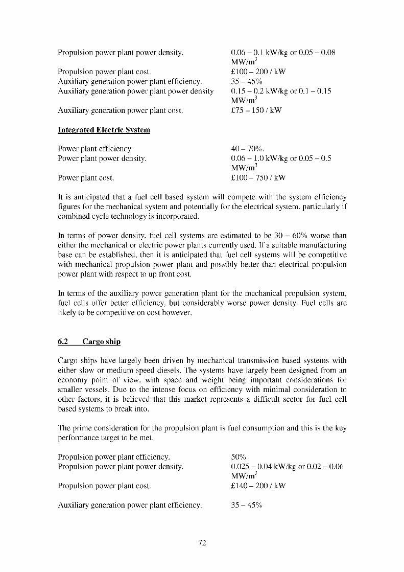
Propulsion power plant power density.
Propulsion power plant cost.Auxiliary generation power plant efficiency. Auxiliary generation power plant power density
Auxiliary generation power plant cost.
0.06 - 0.1 kW/kg or 0.05 - 0.08 MW/m3£100 - 200 / kW 35 - 45%0.15 - 0.2 kW/kg or 0.1 - 0.15MW/m3£75 - 150 / kW
Integrated Electric System
Power plant efficiency Power plant power density.
Power plant cost.
40 - 70%.0.06 - 1.0 kW/kg or 0.05 - 0.5MW/m3£100 - 750 / kW
It is anticipated that a fuel cell based system will compete with the system efficiency figures for the mechanical system and potentially for the electrical system, particularly if combined cycle technology is incorporated.
In terms of power density, fuel cell systems are estimated to be 30 - 60% worse than either the mechanical or electric power plants currently used. If a suitable manufacturing base can be established, then it is anticipated that fuel cell systems will be competitive with mechanical propulsion power plant and possibly better than electrical propulsion power plant with respect to up front cost.
In terms of the auxiliary power generation plant for the mechanical propulsion system, fuel cells offer better efficiency, but considerably worse power density. Fuel cells are likely to be competitive on cost however.
6.2 Cargo ship
Cargo ships have largely been driven by mechanical transmission based systems with either slow or medium speed diesels. The systems have largely been designed from an economy point of view, with space and weight being important considerations for smaller vessels. Due to the intense focus on efficiency with minimal consideration to other factors, it is believed that this market represents a difficult sector for fuel cell based systems to break into.
The prime consideration for the propulsion plant is fuel consumption and this is the key performance target to be met.
Propulsion power plant efficiency. Propulsion power plant power density.
Propulsion power plant cost.
50%0.025 - 0.04 kW/kg or 0.02 - 0.06MW/m3£140 - 200 / kW
Auxiliary generation power plant efficiency. 35 - 45%
72

Auxiliary generation power plant power density 0.15 - 0.2 kW/kg or 0.1 - 0.15MW/m3
Auxiliary generation power plant cost. £75 - 150 / kW
It is anticipated that a fuel cell based system may struggle to compete with the system efficiency figures, particularly when the electric transmission is taken into account. In terms of power density, low temperature fuel cell systems will compete even allowing for the additional space and weight for the electrical components either the mechanical or electric power plants currently used. If a suitable manufacturing base can be established, then it is anticipated that fuel cell systems will be competitive with mechanical propulsion power plant and possibly better than electrical propulsion power plant with regards to up front cost.
6.3 Offshore vessel
The actual role and operation of the offshore support vessel dictates the attractiveness of adopting electric propulsion or not. Many types of vessels, particularly those designed for the specialist roles, such as Floating Production Storage and Offload (FPSO) and semi-submersible (or other) drilling and exploration vessels, have adopted electric propulsion as a standard fit.
Flexibility and reliability are two of the key attributes of the propulsion systems designed for offshore vessels. Specialist categories also have specialist requirements. For instance FPSOs require a high installed power, typically supplied by gas turbines to minimise the volume and weight of the power plant.
Mechanical System
Propulsion power plant efficiency. Propulsion power plant power density.
Propulsion power plant cost.
35 - 45%0.2 - 0.5 kW/kg or 0.1 - 0.25MW/m3£100 - 200 / kW
Auxiliary generation power plant efficiency. Auxiliary generation power plant power density
Auxiliary generation power plant cost.
35 - 45%0.15 - 0.2 kW/kg or 0.1 - 0.15MW/m3£75 - 150 / kW
Integrated Electric System
Power plant efficiency Power plant power density. Power plant cost.
40 - 70%.0.2 - 1 kW/kg or 0.1 - 0.5 MW/m3 £100 - 750 / kW
It is anticipated that a fuel cell based system will compete with the system efficiency figures for the mechanical and electrical system. In terms of power density, fuel cell systems are estimated to be at least 60% worse than either the mechanical or electric power plants currently used. If a suitable manufacturing base can be established, then it
73

is anticipated that fuel cell systems will be competitive with mechanical propulsion power plant and possibly better than electrical propulsion power plant in terms of up front cost.
74

7 Barriers To Implementation
Introduction
Introducing a new type of technology into an established market place is never easy. In addition to potential market inertia - the “if it isn’t broke, don’t fix it” attitude - new technologies are seldom competing on a level playing field, particularly in a conservative market where operational experience is a major influence on design and procurement decisions. Whilst the benefits offered by a new technology must be desirable, attention must focus on the technical hurdles or barriers to be overcome prior to successful adoption of the technology.
The situation is aggravated if the technology investigated is of a relatively novel or immature status, as the confidence in achieving the desired operational performance is correspondingly lower than a mature technology. The balance between the focus on potential benefits and potential barriers is dependent on the nature of the market. This section outlines the likely perceived technical barriers that will need to be overcome prior to fuel cells becoming a feasible option across the range of marine applications. As already discussed, different sectors of the marine market have different degrees of conservatism or innovation, depending on the market drivers acting on that sector.
Consequently, each of the barriers discussed will have differing levels of importance for different market sectors, however they are all considered to be significant and will require mitigation in the form of further research or demonstration.
The barriers to the adoption of fuel cells can be categorised as:
7.1 Maturity of Technology
Fuel cell power generation is not a mature technology, and when competing with diesel engines, diesel generators, gas turbines and gas turbine alternators, they are competing with well understood, proven and reliable technology, whose supporting infrastructure is now well established and economy and performance are well defined and widely accepted.
The performance and characteristics data expressed in this report, are based on testing and evaluation work relating to small power installations. The information relating to fuel cell generation plant in the power band necessary to propel large commercial ships, is based on extrapolation. It is assumed that fuel cells would behave rationally when ‘built up’ into large power installations, although there is no supporting evidence that this is the case. It may be that the extrapolation is modified by economies of scale or by the arrival of unseen factors of limited influence in small scale installations.
In addition, performance characteristics that are traditionally based on historical data, particularly those for availability, reliability and maintainability (ARM), may well be viewed with suspicion if supporting evidence is not available. In these circumstances, demonstration of ARM performance and derivation of Mean Time To Overhaul
75

(MTTO), Mean Time Between Overhauls (MTBO) and Mean Time Between Failures (MTBF) for a marine type fuel cell would be highly desirable.
Any cost data available for fuel cells will be skewed by the fact that the sources are land based, small scale prototypes. The immaturity of the fuel cell system will be reflected in a high cost, further boosted by the minimal support, spares, distribution and manufacturing infrastructure present. Any cost data predicted for large size marine fuel cells may benefit from an evaluation of the material (in terms of nature, quantities and ease of working) required for the construction of the cell. As previously stated, any prediction must be acknowledged to be at risk.
7.2 Fuel Issues
Comparative fuel consumption figures for fuel cells, derived from experience, have frequently been based on “beneficial” fuels for fuel cells, such as hydrogen, methane or methanol, whereas those for conventional prime movers have been based on one of a range of diesel oils. Where possible, the fuel consumption figures quoted in this report have been normalised to account for the differing calorific values of the different fuels. However, the predicted advantageous fuel consumption of fuel cells is likely to be viewed with reservations (at best) and outright suspicion (at worst), until it can be verified with a marine- applicable fuel (be it an existing, developed (low sulphur) or new fuel).
In addition to the above issue of fuel consumption, current conventional marine fuels have relatively high concentrations of sulphur (including those fuels deemed “low sulphur”) and heavy metals, typically 0.5 - 6% sulphur. It is known that fairly low concentrations of sulphur (30 ppm) will poison fuel cell catalysts and it is expected that any heavy metals present will have a further detrimental effect.
There is currently no significant infrastructure for the distribution of alternative marine fuels to diesel based ones. Any requirement for a global distribution system for a new fuel is likely to be extremely expensive and pose a serious barrier to the adoption of fuel cells for trans-continental shipping operating out of a wide variety of ports.
Adoption of a new fuel will require new procedures for storage and handling. Fuels such as hydrogen, methanol or methane offer different hazards to diesel based fuels. These safety hazards are associated with risk to crew of exposure to the fuel and risk to the vessel, particularly in terms of fire hazard. Methanol for instance is toxic, burns with a colourless odourless flame, posing special additional hazards for fire detection and fire fighting. Fuels with high volatility, low flash points, toxic or irritant characteristics or a high explosive potential are not desirable for ships, though the special procedures and techniques utilised to carry such items as cargo could be adapted for fuel carriage and handling.
It is worth noting that an increased fuel cost, above the cost of conventional fuels, will start to offset any fuel economies achieved by a new technology. The marine market is not concerned with a reduction in fuel consumption per se, but the cost of the fuel consumed. Consequently any new fuel that may be used, must not cost more, in terms of
76

percentage price rise, than the percentage reduction in fuel consumption achieved by the new technology. This takes into account the fact that fuel consumption comparisons are currently not based on equivalent fuels.
Reformation of Existing Fuels
The alternative to the adoption of a new fuel is to develop appropriate fuel reforming technology to allow the effective use of existing diesel based fuels and thus remove the logistic constraint of having to provide a "special" fuel cell fuel.
For vessels operating long haul, or trans-continental routes, using a variety of ports, onboard reformation may be the best option. This requires a compact reformation unit, so as not to impact adversely on the size and weight of the installed system. The cost of the reformation system will also need to be minimised to maintain competitiveness with conventional technology. Vessels operating shuttle services between only a few ports, such as ferries, may well be able to use onshore reformation facilities at “home” ports. It is possible that if fuel cells become widely adopted onboard ships, then the future will lie in reformation of marine diesel fuels at all existing major fuelling depots, though the investment required for this situation to be achieved, is immense.
7.3 Classification
Before fuel cell based propulsion systems can be adopted for marine use, the classification societies will need to be convinced and reassured that they are safe for these applications. This is achieved by design and type approval against the requirements of the classification bodies.
A key issue will be the demonstration of an acceptable (but not yet quantified) level of redundancy in the system. It is important to avoid single point failures in the power generation plant, the power distribution plant and the supporting auxiliary systems. The requirement to demonstrate this will determine the nature of the installation and combination of the fuel cell stacks.
A related issue to this is the nature of the degradation of the operation of the fuel cell installation following fuel cell stack failure, auxiliary system failure, monitoring alarm or power reduction signal. The required performance will include the degradation of the performance of the auxiliary systems also. This must be achieved in a controlled, safe manner. It is worth noting at this point that whilst it is acceptable for failsafe systems for land based power generation plant to automatically shut down the system, this may not be desirable for a ship based power generation plant. There are situations where the wider safety implications of losing power onboard outweigh the implications of suffering damage to the machinery.
The classification bodies would also look carefully at the control and monitoring of the system, both in terms of normal and emergency operation. The viewpoint would be to ensure the plant remains safe and under control.
77

The use of a new fuel, even if it is derived from a conventional fuel such as Diesel, raises issues for the classification body. Fuels with harmful or hazardous to health characteristics are unlikely to be readily acceptable to the classification bodies. Additionally special precautions will be required for low flash point fuels (the current minimum is 60OC). It is possible that fuels with flash points significantly below this level will not be allowed. Gaseous, pressurised, or highly volatile fuels will require double skinned fuel pipework and tanks. This must be combined with a means of detecting a leak from the innerpipe work or preventing escape of the fuel should the inner pipe fail. This is typically achieved by either flushing the gap between the two skins and monitoring the effluent, or pressurising the gap between the skins so any rupture of the inner pipe leads to a flow in and subsequent loss of pressure, rather than an escape of fuel. Similar precautions may be required for fuel tanks, or within the fuel cell enclosure.
Presence of unused fuel in any part of the exhaust system would require similar double containment precautions. Any other hazardous materials present in the exhaust (e.g. CO) would need to be monitored and effective dispersion ensured at the point of venting.
If detectors are required for warning of leakage of fuel / hazardous substances in the fuel supply or exhaust gases, then careful consideration needs to be given to the detection technology required to identify hazards.
Surface temperatures must be maintained below 220OC, or lagging included in the system, to reduce the hazard of contact combustion of spilled fluids etc. Additionally health and safety requirements with regard to avoiding injury to crew from hot surfaces must be met.
A further issue for consideration is the end disposal of the fuel cell components. Use of heavy metals, asbestos and other hazardous materials or the formation of hazardous byproducts (including any locked in the fuel cell stacks) pose significant problems for disposal. This is an area coming under increasing scrutiny from both the classification societies and also pressure groups (influencing public perception and often government legislation). Any fuel cell design must take end disposal into account and also allow for the influence of the marine environment on the substances used, to avoid generation of harmful substances. A particular example of this is the danger of generating chlorine gas through the accidental electrolysis of seawater. This may primarily be of concern if a vessel is subject to damage, but the salt laden atmosphere is ever present at sea.
7.4 Resistance to Flood, Fire and Collision
Integration of a fuel cell system into a ship must include consideration of the implications of accidents. This typically includes the danger of flooding, shock / rapid acceleration due to collision and fire. Classification bodies will look for resistance to each of these elements (and any combination of them) with any ensuing degradation of performance being achieved in a controlled and safe manner.
Use of redundant stacks or the ability to isolate stacks would allow for minimising the power loss due to damage. The scope of the requirement for this needs to be
78

investigated. Additionally, a damage scenario must be investigated to assess the likelihood of the initial circumstance leading to further hazards e.g. from fuel escape, release of hazardous materials, secondary effects of flooding, increased fire hazard etc.
7.5 Operation and Degradation
The actual mode of operation and control of the numerous fuel cell stacks required for a marine propulsion application has yet to be established. Key issues include:
• How will the fuel cell stacks be configured (as a number of autonomous power sources, as a semi-integrated single power source with stacks, which can be isolated individually, or as a series of stacks combined as a single entity).
• How the power output from the stacks will be controlled and what form will the power management system take.
• How the fuel cell stacks will perform under degraded conditions.• How will reduced power from the fuel cells be managed.• The level of control require (or available) over each of the stacks.• The man / machine interface.
Safety considerations require some redundancy in the propulsion system, to minimise the danger of a single point failure leading to a total loss of power. Consideration needs to be given to how the requisite number of fuel cell stacks are interconnected and how operation of the power generation plant may be maintained subsequent to a failure in one or more of the stacks or their supporting services. This may be in terms of independent units comprising a number of stacks each, serving a common redundant distribution switchboard. Alternatively a single block of stacks may be acceptable, providing any failed or inoperable stacks can be isolated without detriment to the operation of the remainder.
Assuming that the redundancy requirements for classification require the fuel cell system to be installed as a series of individual or semi isolated power sources, then the sizing of these must take due account of the target vessel’s operating profile. It is desirable to match the most efficient operating range of the power source with the “preferred” power requirement of the vessel. At the same time, it is desirable to avoid cycling power plant and auxiliaries on and off, especially if this may lead to thermal fatigue for hot components. A further consideration is the desirability of being able to share the accumulation of operating hours between the different power sources and associated auxiliaries. This is particularly relevant for vessels with varied operating profiles such as cruise liners.
7.6 Ship Integration Issues
In addition to technical barriers requiring research to be conducted to overcome them, there are a number of issues, relating to integration and operation of fuel cells within a marine application, which require further study.
79

These are the barriers to the actual installation, supply of services and operation of fuel cells in ship applications. The barriers are based on the perception of the characteristics of future fuel cells, based on extrapolation from pilot plants, prototypes and development papers.
These may not necessarily require the gathering and processing of additional data but remain crucial considerations for the successful integration of a fuel cell system into a ship.
7.6.1 Adoption of Electric Propulsion
The output of a fuel cell is a DC electric current. Electric motors are thus required to convert the electrical energy into mechanical energy. The performance of the electric propulsion system must therefore be considered as a potential barrier in the market sectors where the benefits of electrical propulsion have not been demonstrated. The barriers themselves are likely to take the form of an anticipated reduction of fuel cell performance benefits by increases in weight, volume and purchase cost of the propulsion system. The scale of this barrier will depend on the nature of the vessel’s operating profile, the offset achieved from the beneficial characteristics of electric propulsion and any improvement in electric system performance achieved over the next 5 - 10 years.
7.6.2 Provision of Services
Current designs and prototype fuel cells tend to concentrate on land based power generation or small boats, where access to an air supply is relatively straightforward. The situation onboard a larger vessel, where the fuel cell power plant is likely to be buried in the depths of the ship, is not as straight forward. The requirement to supply air, via downtake trunking, to the fuel cell will need to be investigated. The flow rate of air through fuel cell plant of the size required for typical large scale marine propulsion has not been quantified; hence the downtake sizes cannot be specified. In addition the sensitivity to pressure loss in downtake trunking is not known.
Whilst it is expected that fuel cells will require little in the way of services (except oxygen drawn from air) the services for any fuel reformation plant required need to be taken into account. Until the requirements for the fuel reformation plant are understood, these requirements can not be defined.
7.6.3 Exhaust System
Exhaust gases from the fuel cell system will need to be extracted from the machinery space and vented to atmosphere. The requirements for the system well depend on the quantity and constituents of the exhaust gases. It is expected that the exhaust gases will contain at least unused fuel and CO. The presence of unused fuel and CO poses potential safety hazards as the one is a fire hazard and the other is poisonous. Whilst it is proposed that the unused fuel is burnt off to drive the air supply compressor or some
80

other auxiliary equipment, it must still be transported to the burner unit. The nature of the fuel i.e. in a gaseous form, requires special precautions to prevent its escape from the exhaust system into the ship, equivalent to those for the fuel system. The same is true for the CO contained in the exhaust. Exact precautions may be determined by the classification bodies, but are likely to include double skinning the exhaust ducting with monitoring to identify any.
7.6.4 Thermal Enclosure
Fuel cells operate above ambient temperature (between 50 - 200OC for low temperature and 500 - 1000OC for high temperature fuel cells). Whilst they may be self sustaining once they are running, utilising the heat given out by the electro-chemical reaction, heat must be provided on start up. This will require the fuel cell to be installed in some form of furnace or oven, itself within or including a thermal enclosure. The size, capacity and physical design requirements of this furnace are not yet understood.
The temperatures associated with even high temperature fuel cells (up to around 1000OC) are not excessive when compared to more conventional equipment such as diesels, gas turbines or steam boilers. Of these three items the thermal enclosure requirements are most closely matched to those of a boiler, both units having a large volume at a fairly even temperature. It is believed that the technical difficulties posed by the requirements for a thermal enclosure will not exceed those currently experienced for (say) a gas turbine enclosure. The key issues are maintaining a safe surface temperature and integration of other requirements (e.g. fixed fire fighting) with the enclosure.
7.6.5 Monitoring
Consideration needs to be given to the monitoring requirements of the fuel cell power plant and the associated auxiliary systems. It is expected that the following will be required as a minimum:
• Quality of fuel entering the reformer (if used)• Quality of fuel entering the fuel cell (specifically quantity of sulphur and heavy
metals)• Monitoring of fuel leakage from fuel pipes• Monitoring of exhaust gas for harmful by products (specifically unused fuel and CO)• Monitoring of exhaust gas leakage from exhaust system• Fuel cell plant power output• Fuel cell plant temperature• Fuel Cell plant pressure• Consumer power demand• Fuel cell power generation plant available reserve• Status of auxiliary equipment (running, stopped or “tripped”)
81

7.6.6 Removal Routes
It is anticipated that elements of the fuel cell system, principally the fuel cell stacks and any reformer catalyst beds, may have to be replaced at intervals throughout the system life. Ideally these intervals should coincide with the 5 year periodicity of the major surveys required for classification of the ship. A better understanding of the implications of removal of the stacks is required. In particular the scope of removal routes required and whether these can be integration into the ships spaces without compromising operability and whilst minimising work in way for removal.
The alternative approach, of removing components through holes cut in the hull is less desirable or may even be unacceptable from an operational point of view, as this is likely to represent a considerable down time for the vessel.
A balance needs to be established between the space penalty associated with the clear dedicated shipping routes required for rapid removal and the downtime penalty and associated loss of earnings associated with the time required for removal of the stacks though holes cut in the side of the ship.
7.7 Summary
The barriers of implementation can be summarised as follows:
> high cost of catalysts, anodes, electrolyte and other active fuel cell material> thermal control problems> difficult fuel processing requirements (especially for low temperature fuel cells)> system complexity (especially for low temperature fuel cells)> start-up time, especially for high temperature fuel cells> high reformer cost, especially in small systems and when external reforming is
applied> low volumetric power density compared to conventional technologies> carbon monoxide intolerance of electrodes in the case of PEM-FCs> high cost of membranes (for solid polymer electrolyte fuel cells)> low efficiency of the oxygen electrode> deterioration of the cost/performance ratio in small systems; and> periodic cell replacement> costs of raw materials
82

8 Conclusions
The major conclusions can be summarised as follows:
Fuels
The most significant barrier to the widespread acceptance of fuel cells in marine applications is the suitability of available fuels.
If as expected, logistics and economics continue to encourage owners to run their vessels on heavy fuel or marine fuel oil, then a major development effort is required to process these into “fuel cell friendly” fuels. If the nature of the fuel were required to change significantly, then the global distribution infrastructure, required for the supply of marine fuels would require significant and probably prohibitively expensive, investment.
Efficiency
Whilst the theoretical efficiency of a fuel cell exceeds that achieved using conventional technology (unless extensive use of combined cycle techniques are possible), the actual efficiencies realised by prototype plants are roughly equivalent to the better medium and slow speed diesel engines. Future development of gas turbines and diesels predict a 10 - 15% increase in performance, expected to be achieved primarily though steam or water injection into the combustion process.
For the vast majority of marine applications, fuel cell efficiency will have to beat the current best performance of ~ 50% and have an additional 10 - 15% increase in hand to show a clear and sustainable advantage over conventional technologies. If this is achieved, then the fuel cell is likely to be a desirable power source, as many vessels will make some sacrifice in terms of power density if fuel savings can be realised. If these efficiency targets are not met, then fuel cells will only be able to target niche markets for specialist applications.
Emissions
Whilst all fuel cells promise excellent emissions performance, it is predicted that a decrease in NOX emissions of 50% below the targets set out in MARPOL Annex VI would be required before this severely affects the economic argument between diesel engine and fuel cell operation. Gas turbines already offer considerably improved performance over diesel engines for NOx emissions, albeit with an efficiency penalty. Fuel cells may replace some gas turbines as “green” power sources for environmentally sensitive applications, i.e. in-harbour power generation where a ship to shore umbilical is not a practical alternative.
83

Power Density
In terms of power density, it appears that fuel cells will struggle to compete with diesel engines and gas turbines. Fortunately, whilst it is an important consideration for all ships, power density is only a key design driver for very small or very fast vessels.
Transient Response
System start-up time and the ability to respond to rapid changes in load may be an issue for certain fuel cell systems. The thermal inertia of high temperature technologies, both MCFC and SOFC, implies a start-up disadvantage relative to low temperature stacks. However if a PEMFC system utilises a hydrocarbon fuel, its fuel processor will operate at a significantly higher temperature than the stack and thus at least partially negate this advantage.
Unlike automotive applications in most cases the duty cycle is relatively predictable and thus start-up limitations are less of a concern. The ability to increase power output or shed load is likely to be a more significant problem. This report has indicated early response characteristics for both low and high temperature systems but insufficient data is available on hydrocarbon fuel processor and high temperature fuel cell stack cyclic load behaviour to comment further. This is an area recommended for further work.
Applications & Markets
If the theoretical efficiency benefits of fuel cells can be realised and the predicted low maintenance performance achieved, then they will be applicable to many types of vessels, excepting those requiring high power density. In particular, intercontinental cargo vessels, cruise liners and conventional ferries may all be suitable applications for fuel cells.
Of these, the most suitable is likely to be the cruise liners, where the additional benefits of low noise levels and environmentally friendly performance (and image) may improve revenue earning potential. Cruise line owners and operators have already proven their willingness to consider new technology, against the background of a very conservative industry, by adopting electric propulsion.
Specialist applications that may well be suited to fuel cells include acoustic research vessels, which will benefit from the low noise levels, and tourist vessels requiring especially good environmental performance.
The least suitable market will be fast ferries who are unlikely to be tempted away from high-speed diesels and gas turbines. The value this application puts on achieving high power density offsets a high maintenance burden or high fuel consumption.
Caveat
84

The above is dependent on fuel cell technology achieving or coming close to their theoretical efficiency without significant weight and space penalties. Fuel cell technologies must also demonstrate that their forecast cost and reliability targets can be achieved.
85

REFERENCES
[1] MAN B&W Report “Trends in the Volume and Nature of Propulsion Machinery Demand - the Low Speed Sector”, Dec 1999.
[2] Stapersma, D et al. “The Potential of the 2 Stroke Diesel Engine”, ENSUS 2000, Sept 2000
[3] Chomiak, J et al “Steam Injected Diesel (STID) Engine: Some Basic Considerations”, ENSUS 2000, Sept 2000.
[4] Rosen, P et al “Wet Cycles for Generation of Power Heat and Refrigeration”, ENSUS 2000, Sept 2000.
[5] Privette, R.M. et al 2.5 MWe PEM Fuel Cell System for Navy ShipService Power
[6] Steinfeld, G. et al Direct Carbonate Fuel Cell for Ship Service Applications
[7] Progress in PEM fuel cell systems for surface ships and submarines, Warship Technology Oct 1999
[8] Sattler, Gunter Fuel cells going on-board, Journal of Power Sources, pp61-67,86,2000
[9] Ponthieu, E. Status of SOFC Development in Europe, Sixth International Symposium on SOFC, Honolulu, 17-22th October 1999
[10] Fuel Cells Bulletin, Sep 2000, No 20, Elsevier Science Ltd
[11] Marine log, 24 August 1999
[12] Doctor, A. et al. Reformer for gasoline and gasoline like fuels, 2000 Fuel Cells Seminar Portland, Oregon
[13] Carpenter, I.W., et al Alternative Feeds for Fuel Processing by Partial Oxidation and Autothermal Reforming, J. Matthy, ETSU report F/02/00117/REP, 1998
[14] Krumpelt, M. et al. Authothermal reforming for fuel cell systems, 2000 Fuel Cells Seminar Portland, Oregon
[15] Maru, H. et al. ERC program Overview, CD Proceedings of the Fuel Cells 96 Review Meeting
[16] International Convention for the prevention of Pollution from Ships, 1973, as modified by the Protocol of 1978 (MARPOL 73/78)
86

[17] Nurmi, Jari Environmental Aspects - Fuel Emissions, Norwegian Society of Chartered Engineers, Diesel Electric Propulsion 1998
[18] U.S. Coast Guard Report No. CG-D-01-00, page 18, 1999
[19] Fairplay - World Shipping Statistics 1997
[20] Goubault, P. FC Power plants for surface fleet applications, Naval EngJ May 1994, p 59
[21] Ballard 250 kW CHP information brochure
[22] Marine Diesel Engines, www.dieselnet
[23] Applications of fuel cells to surface ship propulsion systems, IHI Engineering Review, Vol. 26, No. 4 October 1993
[24] Satzberg, S., R. Naval Fuel Cell Programs, Joint Fuel Cell Technology Review August 19999, Chicago, IL
[25] Sukkel, J Two Years Experience with the 100 kWe Cogeneration Unit at Arnhem, Fuel Cell 2000, Switzerland
[26] Moritz, B, et al. Fuel cell hybrid plant system design, Powergen 2000,USA
[27] US Costguard report CG-D-12-99
[28] Fuel bunker prices derived from MER
[29] Allen, S “Marine Applications of Fuel Cells”, S Allen, Journal of Naval Engineering, February 1998.
87

APPENDICES
A.1 INTER-CONTINENTAL CARGO VESSEL
Introduction
With the exception of perishable and precious goods, the vast majority of the world’s export tradable goods are transported by sea at some time. The ships that transfer this huge quantity of cargo to all corners of the world vary to suit the cargo needs. Some principal design drivers are comparable despite differences in specific ship details.
The main ship types considered within this category are:
• Bulk dry cargo ships• Crude oil carriers• Bulk ore carriers• Container ships• Chemical tankers• Gas tankers• Vehicle Transporters
Each of these merchant ships utilise economy of scale relative to the cargo, as their revenue earning potential is directly related to the quantity of cargo that may be transported on a voyage. This is partially explained by the fact that energy consumption per unit cargo per kilometre transported, decreases with increasing size of ship. The specific energy consumption for large container vessels and bulk carriers is significantly less than that for truck and ro-ro vessels - as a consequence inter-continental ships are tending to be ever larger to minimise the specific energy consumption with regard to cargo carrying capacity. The increase in hull size improves the optimisation of cargo space and simplifies the loading procedures. This often results in considerable spaces fore and aft for machinery. The size and weight of propulsion machinery is generally becomes less import, when compared to the vessel displacement and cargo capacity.
For merchant ships travelling the oceans for sustained periods, economy is of principal importance, as the usage factor for such a merchant ship is typically 75%, when compared to 2% for a domestic motor car.
A-1

Figure A. 1.1: Very Large Crude Carrier (VLCC) used to transport crude oil in bulk
Propulsion system requirements
The operating profile of such merchant vessels is regular and fairly continual. When in harbour main propulsion machinery is inactive. Generally, exit from harbour will be undertaken with tug assistance and the propulsion system will ramp up, as the vessel leaves the approaches to a port, to deliver full power. When in transit the system operates at design condition close to or at maximum power for sustained periods, with only small variations for manoeuvring or unprecedented circumstances.
The auxiliary hotel load will remain fairly constant during transit, with a possible fluctuation between day and night demands, but otherwise is expected to be relatively flat. There may be a load spike whilst unloading is conducted, depending on whether cargo pumps / derricks etc. are used or whether the vessel is reliant on port facilities.
The size of these merchant ships, particularly tankers and container ships that approach 300m length, require high installed power, up to 60 MW for the largest container vessels, but typically between 10 and 25 MW. Auxiliary loads tend to vary between 2.5 and 4 MW, though large container vessels may require up to 17 MW. Fuel bunkerage tends to vary between 2000 to 5000 m3, with large container vessels requiring up to 13000 m3 of fuel. Typical consumption figures vary between 30 and 60 tonnes per day. As would be expected the high installed power of container vessels is reflected by a high consumption, up to 250 tonnes per day. The small crew requires there to be minimal maintenance load whilst at sea and the propulsion system must therefore be simple and reliable.
With respect to these deep-sea cargo vessels, the design of any propulsion system needs to meet certain well established criteria in order to be desirable from the operator / owner viewpoint:
• Low specific fuel consumption values• Low operating costs
A-2

• Relatively high power output• Sustained reliability• Low maintenance whilst at sea
Current system solutions
With considerable weight and space capacity available and an emphasis on efficiency, the current choice for large merchant ships is slow speed diesel engines. These can achieve thermal efficiencies beyond 50% and a specific fuel consumption of 160 g/kWh on low cost, low grade, heavy fuel oil. The propulsion system is simple in that these slow running engines may be directly coupled to a single drive shaft turning a large diameter fixed pitch propeller. If a reduction gearbox is required to match engine output and propeller input, then it is a straightforward unit with low reduction ratios. Astern manoeuvres are achieved by operating the engine in reverse, or by generating reverse thrust with a controllable pitch propeller.
Figure A.1.2: Typical large capacity container vessel
Slow speed diesels are reliable, well understood and widely used; and although installation costs are high the maintenance costs are relatively low and prove popular with ship owners due to their operating economics. Their simple nature is well suited to operation and maintenance on board a ship - under what can be a very testing environment with limited labour resource.
Typically, the resulting characteristics of the propulsion system are:
• Single, large, slow speed diesel delivering high power (between 10 and 60 MW at 80 - 250 rpm)
• Short propeller shaft driving large, diameter slow turning propeller (80 - 150 rpm)• Operation on cheap heavy fuel oil with fuel consumption around 160 g/kWh• Excellent reliability due to low wear rates from slow moving parts• Auxiliary power produced by separate diesel generator sets
A-3
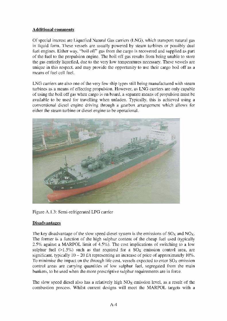
Additional comments
Of special interest are Liquefied Natural Gas carriers (LNG), which transport natural gas in liquid form. These vessels are usually powered by steam turbines or possibly dual fuel engines. Either way, “boil off’ gas from the cargo is recovered and supplied as part of the fuel to the propulsion engine. The boil off gas results from being unable to store the gas entirely liquefied, due to the very low temperatures necessary. These vessels are unique in this respect, and may provide the opportunity to use their cargo boil off as a means of fuel cell fuel.
LNG carriers are also one of the very few ship types still being manufactured with steam turbines as a means of effecting propulsion. However, as LNG carriers are only capable of using the boil off gas when cargo is on board, a separate means of propulsion must be available to be used for travelling when unladen. Typically, this is achieved using a conventional diesel engine driving through a gearbox arrangement which allows for either the steam turbine or diesel engine to be operational.
Ligure A. 1.3: Semi-refrigerated LPG carrier
Disadvantages
The key disadvantage of the slow speed diesel system is the emissions of SOx and NOx. The former is a function of the high sulphur content of the cheap fuel used (typically 2.5% against a MARPOL limit of 4.5%). The cost implications of switching to a low sulphur fuel (>1.5%) such as that required for a SOx emission control area, are significant, typically 10 - 20 £/t representing an increase of price of approximately 10%. To minimise the impact on the through life cost, vessels expected to enter SOx emission control areas are carrying quantities of low sulphur fuel, segregated from the main bunkers, to be used when the more prescriptive sulphur requirements are in force.
The slow speed diesel also has a relatively high NOx emission level, as a result of the combustion process. Whilst current designs will meet the MARPOL targets with a
A-4

degree of spare capacity, if emissions levels tighten sufficiently, there will be a point at which an additional system is required to treat the engine exhaust. Such a system will have a significant impact on the running cost of the engine.
Tightening of NOX and SOX legislation will progressively reduce the attractiveness and economic benefits of slow speed diesel engines, due to increased fuel cost and increased engine operating cost. This would deprive the engine of the very characteristics that make it the choice for long haul vessels and may open up the market to a medium speed diesels using better grade fuel and emitting less NOX, or a new technology.
Of lesser importance is the slow response of the system to changes in load. This is not a serious issue, as large cargo vessels, with a high inertia, tend to get priority in sea lanes (on a might is right basis). The size and bulk of these ships dictates a high inertia and reluctance to change speed / direction as they pass through the water. Consequently they and are not capable of undertaking major manoeuvring operations (berthing and leaving berth are undertaken with tug assistance).
The power density of the system is also very low. Again, this is not a serious issue as the requirement to carry bulk cargo dictates the vessel size and there tends to be sufficient available space to install a large system.
A-5

A.2 COASTAL CARGO VESSEL
Introduction
Cargo ships for coastal regions and inland waterways are differ greatly from their deep sea relatives, and provide a very different service. Coastal cargo ships are much smaller and are intended to travel around the inland waterways and littoral zones in order to service inland ports and depots. Ship types in this category include:
• Specialist tankers• Container ships• Dry bulkers• Barges• General multi cargo ships
These smaller utility ships provide a service to the ports and larger merchant ships that are unable to enter smaller ports and often travel far inland on restricted waters. This is because the large tankers and container ships having loaded drafts up to 20 metres, and beams of 50 metres, find manoeuvring or unloading away from the major ports extremely difficult.
Figure A.2.1: Coastal container vessel
Propulsion system requirements
To operate effectively these ships must exploit the balance between size and economy, because they must remain small enough to operate easily in restricted waters yet carry enough cargo to make the trip worthwhile. Consequently, smaller slower coastal cargo ships have reasonably low installed propulsion power, often twin shafts to improve manoeuvrability and to keep propeller diameter (and hence vessel draught) low.
A-6

The operating profile of these vessels is generally regular and fairly continual. There is a strong cyclic element due to the short nature of the journey and the relatively long periods spent manoeuvring. In addition, whilst manoeuvring typically utilises about half the total propulsive load, in practice the operation will lead to rapid cycling of the system from near full ahead to near full astern. Larger vessels may use tug assistance to berth, but smaller vessels may well need to undertake these operations without assistance. When in harbour main propulsion machinery is inactive.
The auxiliary hotel load will remain fairly constant during transit, with a possible fluctuation between day and night demands, but otherwise is expected to be relatively flat. There may be a load spike whilst unloading is conducted, depending on whether cargo pumps / derricks etc. are used or whether the vessel is reliant on port facilities. Load spikes will also be present during manoeuvring, as bow and stern thrusters are used. Typically propulsion loads vary between 1.5 to 20 MW, the larger end of the scale being represented by fast ro-ro freight. Auxiliary loads may be anywhere between about 0.5 and 5 MW. Fuel carriage varies between less than 100 m3 and in excess of 1200 m3, with fuel consumption being about 15 - 20 tonnes per day.
Typical requirements for the system are:
• Propulsion system operational flexibility• Economic operation• Reliability• Manoeuvrability
Current system solutions
Typically coastal cargo ships are fitted with a simple diesel mechanical system, driven by a medium speed diesel engine. A twin shaft installation may be adopted to improve manoeuvrability or to reduce the vessel’s propeller diameter and hence draught. This offers a favourable combination of economy over a wide power range, and the opportunity to drive additional machinery, such as an alternator. It is common for an auxiliary alternator to be driven via a power take off from the shaft(s) or main engine(s), this is supported by up to three or four auxiliary alternators, required for additional capacity, emergency back up and times when in port.
A-7

Figure A.2.1: Typical coastal mixed cargo vessel
Much of the design solution is focussed on maintaining a combination of reliability, performance, and economics; diesel engines thus providing a reliable and well understood technology for this purpose.
Typically the propulsion and power generation system consists of:
• Medium speed diesel engines operating between 500 - 750 rpm providing 4-8 MW• Specific Fuel Consumption (sfc) between 170 - 180 g/kWh• Twin shafts with gearbox reduction to controllable pitch propellers• Bow thrusters and possibly stern thrusters• Rapid throttle response• Simple design• Supplementary auxiliary machinery
Disadvantages
Whilst fuel cost is not considered a disadvantage per se, the efficiency of the engines used for coastal vessels is not as good as that for intercontinental vessels. This is due to trade off struck between fuel consumption, machinery size, part load capability and machinery response.
The emissions from medium speed diesels, whilst better than slow speed diesels, are still vulnerable to future increases in legislation, particularly those governing coastal or inland waterways and ports. Additionally those vessels operating on HFO are vulnerable to reduced SO% emission targets. Coastal vessels are also subject to public scrutiny as they are often within view of the shoreline or are seen entering or leaving coastal towns. Consequently an emphasis on low or no smoke or particulate emission is placed on these vessels.
A-8

The mechanical drive system requires a Controllable Pitch Propeller (CPP) both for reversing and also to reduce excessively low load running of the main propulsion diesels during manoeuvring. This low load running (typically defined as below 20 - 30 % maximum continuous rating) can lead to detrimental build up of carbon in the engine cylinders and is to be avoided. The CPP adds another system and set of working fluids to the vessel, thus increasing maintenance requirements. It is also less efficient than a fixed pitch propeller.
A-9
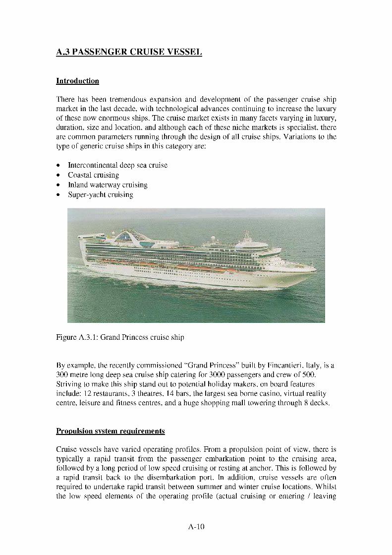
A.3 PASSENGER CRUISE VESSEL
Introduction
There has been tremendous expansion and development of the passenger cruise ship market in the last decade, with technological advances continuing to increase the luxury of these now enormous ships. The cruise market exists in many facets varying in luxury, duration, size and location, and although each of these niche markets is specialist, there are common parameters running through the design of all cruise ships. Variations to the type of generic cruise ships in this category are:
• Intercontinental deep sea cruise• Coastal cruising• Inland waterway cruising• Super-yacht cruising
Figure A.3.1: Grand Princess cruise ship
By example, the recently commissioned “Grand Princess” built by Fincantieri, Italy, is a 300 metre long deep sea cruise ship catering for 3000 passengers and crew of 500. Striving to make this ship stand out to potential holiday makers, on board features include: 12 restaurants, 3 theatres, 14 bars, the largest sea borne casino, virtual reality centre, leisure and fitness centres, and a huge shopping mall towering through 8 decks.
Propulsion system requirements
Cruise vessels have varied operating profiles. From a propulsion point of view, there is typically a rapid transit from the passenger embarkation point to the cruising area, followed by a long period of low speed cruising or resting at anchor. This is followed by a rapid transit back to the disembarkation port. In addition, cruise vessels are often required to undertake rapid transit between summer and winter cruise locations. Whilst the low speed elements of the operating profile (actual cruising or entering / leaving
A-10

harbour) require low average propulsion power, there will be a high cycling of the demand on the propulsion system, typically from half speed ahead to full astern. Harbour entry / exit and berthing are generally undertaken with tug assistance.
The ship service load is likely to show a daily cycle with extremely high loads during the day, falling of to a base (though still significant) hotel load during the night. Additionally, manoeuvring will require significant power to bow and stern thrusters. This load is likely to have a very rapid cyclic nature.
The very high service power need for cruise ships clearly results as a function of its purpose, and is hugely important when considering the implications of power loss when paying passengers are on board. The usage factor for power generation machinery tends to be very high on cruise ships during the day, with some drop off experienced at night.
The installed power requirements for cruise ships varies widely, with the size of the vessels. Typically, larger vessels tend to be all electric, with installed powers between 48 and 66 MW. Smaller vessels are more likely to be conventionally powered, with propulsion loads in the order of 10 - 15 MW and service loads up to 20 MW. The larger vessels tend to carry between 2000 and 3500 m3 at 150 to 200 tonnes per day. The smaller vessels may carry around 1000 m3 at a consumption of around 90 to 100 tonnes per day.
Key design drivers for cruise ships are substantially different to that of other merchant ships, and may be summarised as follows:
• High reliability• High installed propulsion power availability• High continual service power supply• Low noxious emissions• Low and predictable maintenance• Economic operation• Safe, reliable response to load changes.• Flexibility in the operation of the propulsion and power generation machinery• Enhancing passenger comfort and improving on board environment• Low noise and vibration
A-11

Figure A.3.2: Coastal / short haul cruise ship
Current system solutions
Typically, cruise ships are either ‘all electric’, or not. In electric systems, power is generated by an arrangement of generator sets to form a common power station supplying a distribution network with propulsion effected by electric motors. Power generation in this manner follows a more predictable profile, and fluctuations become less noticeable than installations where separate auxiliary machinery is used, and total installed power ratings are generally higher.
The complexity of the electric generation and distribution network is high, and the flexibility of the prime movers needs to match the varied loading placed on them. Although the total installed power is high on cruise ships, the time generating maximum power is relatively low, as the propulsion power required for cruising may be half that required for full speed transit.
Current solutions for prime movers in electric ships are predominantly diesel engines with gas turbine driven alternators apparent in some large power station complexes, where high continual electric demand on board is present. Gas turbines and diesel engines are well understood and provide reliable generator sets in the marine environment.
The availability and reliability of the components required to assemble such propulsion systems presents no limitations to the system reliability and integrity. The technology of diesel and gas turbine driven alternators provides power distribution networks with reliable power sources that are easily integrated into cruise ships. The operating profile of cruise ships tends to be regular and predictable, as their operation is based around a schedule of known operations and defined procedure; further supporting the integrated electric power station concept for cruise ships.
A-12
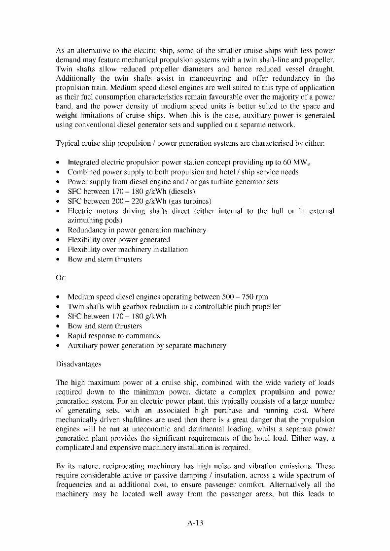
As an alternative to the electric ship, some of the smaller cruise ships with less power demand may feature mechanical propulsion systems with a twin shaft-line and propeller. Twin shafts allow reduced propeller diameters and hence reduced vessel draught. Additionally the twin shafts assist in manoeuvring and offer redundancy in the propulsion train. Medium speed diesel engines are well suited to this type of application as their fuel consumption characteristics remain favourable over the majority of a power band, and the power density of medium speed units is better suited to the space and weight limitations of cruise ships. When this is the case, auxiliary power is generated using conventional diesel generator sets and supplied on a separate network.
Typical cruise ship propulsion / power generation systems are characterised by either:
• Integrated electric propulsion power station concept providing up to 60 MWe• Combined power supply to both propulsion and hotel / ship service needs• Power supply from diesel engine and / or gas turbine generator sets• SFC between 170 - 180 g/kWh (diesels)• SFC between 200 - 220 g/kWh (gas turbines)• Electric motors driving shafts direct (either internal to the hull or in external
azimuthing pods)• Redundancy in power generation machinery• Flexibility over power generated• Flexibility over machinery installation• Bow and stern thrusters
Or:
• Medium speed diesel engines operating between 500 - 750 rpm• Twin shafts with gearbox reduction to a controllable pitch propeller• SFC between 170 - 180 g/kWh• Bow and stern thrusters• Rapid response to commands• Auxiliary power generation by separate machinery
Disadvantages
The high maximum power of a cruise ship, combined with the wide variety of loads required down to the minimum power, dictate a complex propulsion and power generation system. For an electric power plant, this typically consists of a large number of generating sets, with an associated high purchase and running cost. Where mechanically driven shaftlines are used then there is a great danger that the propulsion engines will be run at uneconomic and detrimental loading, whilst a separate power generation plant provides the significant requirements of the hotel load. Either way, a complicated and expensive machinery installation is required.
By its nature, reciprocating machinery has high noise and vibration emissions. These require considerable active or passive damping / insulation, across a wide spectrum of frequencies and at additional cost, to ensure passenger comfort. Alternatively all the machinery may be located well away from the passenger areas, but this leads to
A-13

significant portions for the ship that are unavailable for revenue earning. Gas turbines have been adopted in some instances as they have reduced noise and vibration levels, however there is a significant fuel penalty.
The predominant engine in the cruise ship market is the slower of the medium speed diesels. These typically have better emissions performance than slow speed engines, but are still vulnerable to tightening legislation. This is compounded by the fact that the nature of cruise line business takes the ships in to environmentally sensitive areas with tighter emissions limits. Consequently improved environmental performance is continuously being sought. This includes emissions that are not yet the subject of international legislation but are subject to public concern, such as CO2, smoke and particulates.
A-14

A.4 SHORT HAUL / RAPID TURN AROUND FERRY
Ferries are used extensively the world over to transport people, vehicles and goods over sea on numerous routes and to many countries. In recent years, there has been a definite trend towards developing ‘fast ferries’ that are capable of high speed crossings whilst maintaining adequate seakeeping characteristics and economic operation.
For this reason, it may be regarded that there are two main types of ferry:
1. Conventional slow speed ferries, typically optimised for economy of scale2. Fast ferries optimised for crossing time
Figure A.4.1: Typical monohull fast ferry design
Ships that concentrate on fundamentally different issues clearly will have different design drivers, particularly with regard to the propulsion machinery. For this reason, the above named ferry types are discussed individually:
Introduction: Conventional ferries
Roll on-Roll off (Ro-Ro) ships such as the renown ‘cross channel’ ferries have for years provided a regular, reliable service, in all but the severe sea states. The vessels are optimised with respect to maximising the quantity of both passenger and vehicle cargo, with the ability to load all forms of road transport and in some cases railway carriages. When combined with adequate facilities for passengers, these ferries are suitable for all forms of traveller. Types of conventional ferries may be classified by journey time:
• Long haul ferries with passage over 12 hours (cruise ferries)• Ferries with passage times of 2 - 12 hours• Short haul ferries with journeys of a few minutes up to two hours.
A-15

Each of these typically represents an increase in the scale of power requirements.
Introduction: Fast ferries
The development of fast ferries has expanded the ferry market over the last decade, and routes now using fast ferries are seen to compete with other forms of transportation. However, such excitement of the latest generation of fast ferries, must not undermine the majority of ferries that still provide a conventional, reliable and regular service.
High-speed ferries are solely intended to reduce the transit time on a regular route, and consequently optimise the size and density of the structure and machinery in order to maximise cargo potential. In applications where reduced transit times are favourable, high speed services have flourished and are now reliable.
Ships within this high speed category include:
• High speed monohulls• High speed catamarans• Hovercraft• Surface effect catamarans• Hydrofoils
Propulsion system requirements: All ferries
Ferries are one of few marine vessels that operate to a regular and predictable operating profile, with little variation in the cargo characteristics or the route taken. The propulsion system is required to be inactive whilst at port, before manoeuvring out of harbour and embarking on the crossing. Manoeuvring in and out of harbour is usually achieved without tug assistance and consequently there is heavy loading of the propulsion system and bow and stern thrusters. Relative to other vessels, this is a significant period of time (approximately 10% of voyage for short haul ferries). The remainder of the voyage will be at a constant speed, close to or at maximum power.
Ship service power will be fairly steady during transit, but will have significant load spikes during manoeuvring and loading / unloading operations as ramps, cranes and winches are deployed.
A-16

Figure A.4.2: Typical sea-going, conventional short haul ferry
For slow speed ferries that reach 150 metres in length, the installed power is typically around 15 - 35 MW, of which 10 to 25 MW will be for the propulsion system. High speed ferries may require anything between 25 and 70 MW of propulsive power. This is another reason why the power density of the prime movers must be greater in high speed ships. Fuel bunkerage is typically in the order of 200 to 1500 m3. Consumption for conventional ferries is about 15 tonnes per day, but the larger fast ferries may bum this quantity of fuel in an hour.
Figure A.4.3: Short haul inland ferry
A-17

Manoeuvrability is significantly important to any ferry that regularly negotiates harbours and restricted waters; hence the prime movers of the propulsion system must be flexible enough to effect uncompromised docking. This flexibility is reflected in the complexity of the whole propulsion system, when considering the combinations of directional thrust required to manoeuvre a large ferry in port. To minimise turn around time and harbour costs, ferries typically undertake unassisted docking and undocking. This means they require significant manoeuvring capability in terms of bow and stern thrusters and high performance rudders.
Of principal importance is the balance between operating economics and operating performance. Faster crossings encourage passengers to pay more, but lead to increased purchase and running costs of the ferry. Significant deviation either side of the balance will result in some losses, financial or not.
The design speed of fast ferries tends to be approaching the respective speed limitation of displacement craft, hence the power density of the prime movers must be high to exploit the weight and space parameters. On this basis, high and medium speed diesel engines are well suited to this application.
Ferries have been discussed with sub-division by:
1. Conventional slow speed ferries2. Fast Ferries
The requirements for each may therefore be classed as:
1. Slow speed ferries
• Low noise and vibration• Flexibility to variations in operations• Regularity in operation and maintenance• Quick start up and shut down capability• Economic operation• Reliability• Flexibility and system availability
2. Fast Ferries:
• Maintaining economic operation• Reliability• Regularity in operation and maintenance• Quick start up and shut down capability• Power density• Economic operation• Reliability and propulsion system availability
A-18

Current system solutions: Slow Ferries
Typically, these ships are propelled conventionally by mechanical driven shaft lines and propellers. Diesel engines suit the requirements of these ferries well, providing reliable well proven propulsion power with predictable operating and maintenance costs. Auxiliary power is provided by diesel engine generator sets, providing power to the ship's services.
Characterised by:
• Medium speed diesel engines operating between 500 - 750 rpm• Twin shafts with gearbox reduction to a controllable pitch propeller• SFC between 170 - 180 g/kWh• Bow and stern thrusters• Rapid response to commands• Auxiliary power generation by separate machinery
Current system solutions: Fast Ferries
The operating speed of fast ferries reaches up to 50 knots, at which speed there are numerous issues regarding conventional propeller derived marine propulsion. Principally these are related to appendage drag (resistance due to underwater fittings external to the hull), advancing velocities (speed of the propeller relative to the water it is passing through) and propeller cavitation (erosion of propeller surfaces due to the collapse of low pressure pockets on the blade faces). For these reasons, waterjets have evolved as an advantageous means of high speed propulsion, due in main to the lack of machinery projecting into the water.
Medium to high speed (above 900 rpm) diesel engines and gas turbines are suitable to drive waterjets with simplistic gearing, providing the relatively high power density required to pack in the power necessary to propel fast ferries bearing in mind the limited machinery space and weight criticality. In fast catamarans, this space is further limited by the slender shape of the twin hulls.
The installed power for propulsion alone is relatively high for fast ferries, that tend to be restricted to below 135 metres, illustrated by the original series of Sea Cat fast Ferries. Built by Incat, Australia, the sea cats are claimed to eject up to 74 tonnes of water through the 4 waterjets every second when operating at full power.
Leading to typical systems such as:
• Medium or high speed diesel engines operating between 900 - 2000 rpm, or gas turbines
• SFC for medium speed diesels between 170 - 180 g/kWh• SFC for high speed diesels between 190 - 220 g/kWh• SFC for gas turbines between 200 - 220 g/kWh• Multiple shafts (as many as six) with gearbox reduction to the propulsors
A-19

• High speed propulsors such as waterjets and surface piercing propellers• Auxiliary power generation by separate machinery
Disadvantages
Whilst fuel cost is not considered a disadvantage per se, the efficiency of the engines used for short haul ferries is not as good as that for available for intercontinental vessels. This is due to trade off struck between fuel consumption, machinery size, part load capability and machinery response.
The emissions from medium speed diesels, whilst better than slow speed diesels, are still vulnerable to future increases ion legislation, particularly those governing coastal or inland waterways and ports. Additionally those vessels operating on HFO are vulnerable to reduced SOX emission targets. Coastal vessels are also subject to public scrutiny as they are often within view of the shoreline or are seen entering or leaving coastal towns. Consequently an emphasis on low or no smoke or particulate emission is placed on these vessels.
The mechanical drive system requires a Controllable Pitch Propeller (CPP) both for reversing and also to reduce excessively low load running of the main propulsion diesels during manoeuvring. This low load running (typically defined as below 20 - 30 % maximum continuous rating) can lead to detrimental build up of carbon in the engine cylinders and is to be avoided. The CPP adds another system and set of working fluids to the vessel, thus increasing maintenance requirements. It is also less efficient than a fixed pitch propeller.
The combined of a wide variety of propulsion and hotel loads required down to the minimum power, dictate a complex propulsion and power generation system. For an electric power plant, this typically consists of a large number of generating sets, with an associated high purchase and running cost. Where mechanically driven shaftlines are used then there is a great danger that the propulsion engines will be run at uneconomic and detrimental loading, whilst a separate power generation plant provides the significant requirements of the hotel load.
By its nature, reciprocating machinery has high noise and vibration emissions. These require considerable active or passive damping / insulation, across a wide spectrum of frequencies and at additional cost, to ensure passenger comfort. Whilst this is not required to the sorts of levels of comfort that a cruise liner dictate, it can still represent a significant disadvantage.
All the propulsion machinery needs to be installed below the vehicle deck and it is important that services to and from the machinery spaces do not pose a significant detrimental impact on the vehicle deck. This can pose a significant design constraint.
A-20

A.5 RESEARCH & SURVEY VESSEL
Introduction
Although a somewhat subjective remark, it has been stated that more is known about the surface of the moon than the majority of the sea bed, although this is not entirely due to a lack of interest. Oceanographic research is a vastly costly business that has been poorly funded, partly due to the limited perceived economic benefit of the results obtained. An exception to this is the topological and survey work carried out on the worlds continental shelves in support of the dynamic offshore industry, with respect to site surveying, extracting natural resources, cable and pipe laying. The offshore industry is renown for injecting large quantities of financial resource into investigating methods to improve and economise, provided there is viewable potential for future savings. In comparison, little resource is apparent for purely scientific research, although the emphasis on using technology to enhance such work is ever apparent. The main ship types that are contained in this category:
• Scientific research & laboratory ships• Hydrographic research• Topological surveying• Seismic survey• Deployment of Autonomous underwater vehicles• Deployment of remotely operated vehicles• Diving support
Propulsion and power system requirements
The size, shape and complexity of research ships vary enormously, principally due to the huge variation in the work they undertake, and the seas in which they work. Generally these ships are required to be very flexible to variations in the work profile, from the aspects of changed work instruction, weather and time delays, crew changes, specialist equipment and loading. Typical operating profiles are hard to define as the vessels are called upon to undertake a wide variety of tasks. Typical operations may include repeated slow speed travel along a pre determined heading whilst deploying sonar for surveying seabed formations or station keeping whilst sampling seawater or undertaking diver operations. These operation place widely different requirements on the propulsion system. In addition, station keeping requires the interaction of the propulsion system with a computer (or manual) controlled dynamic positioning system. Such a system compares the ships actual location, derived from navigation instruments and a predefined target station. The propulsion system can automatically respond to ensure the two positions correspond to a given tolerance. Dynamic positioning is necessary to ensure the ship maintains station when underwater vehicles, sampling instruments or divers are deployed and the ship must remain directly above the target zone.
Following on from this, support ships are generally sophisticated vessels with the capability to accommodate and operate a wide range of machinery for the diverse nature
A-21
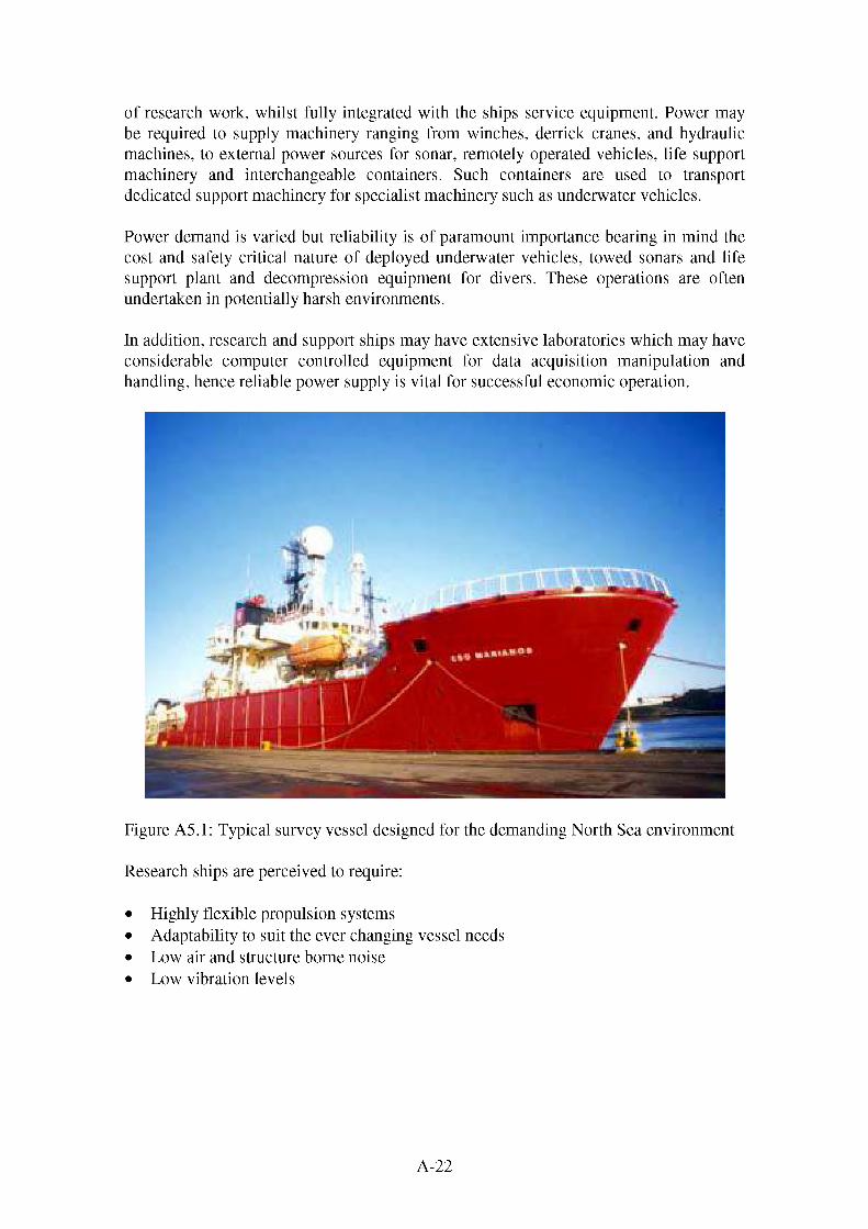
of research work, whilst fully integrated with the ships service equipment. Power may be required to supply machinery ranging from winches, derrick cranes, and hydraulic machines, to external power sources for sonar, remotely operated vehicles, life support machinery and interchangeable containers. Such containers are used to transport dedicated support machinery for specialist machinery such as underwater vehicles.
Power demand is varied but reliability is of paramount importance bearing in mind the cost and safety critical nature of deployed underwater vehicles, towed sonars and life support plant and decompression equipment for divers. These operations are often undertaken in potentially harsh environments.
In addition, research and support ships may have extensive laboratories which may have considerable computer controlled equipment for data acquisition manipulation and handling, hence reliable power supply is vital for successful economic operation.
Figure A5.1: Typical survey vessel designed for the demanding North Sea environment
Research ships are perceived to require:
• Highly flexible propulsion systems• Adaptability to suit the ever changing vessel needs• Low air and structure borne noise• Low vibration levels
A-22

Current system solutions
Currently diesel electric systems are well suited the needs of these ships as diesels provide relatively flat line economy over the power range with rapid response to load variation and start up. Typically larger installations will feature medium speed diesels driving a generator at approximately 750 to 900 rpm, smaller installations may adopt high speed diesel units running up to 2000 rpm.
The propulsion and power generation system is frequently integrated with a dynamic positioning, monitoring the vessels position and controlling it via bow thrusters, and azimuthing propulsors. These latter items are typically propellers installed in pods slung below the hull. The pods are capable of rotating through 360O in a horizontal plane. These propulsors may include a motor in the pod body (podded propulsor) or a geared mechanical drive (azimuthing thruster) and may be used purely for manoeuvring, or for manoeuvring and main propulsion.
The relatively small physical nature of these vessels implies the installed power may be up to 20 MW. Research vessels are relatively technically advanced in both their machinery installation and scope of work, and it is perceived that the owners, builders and operators of such vessels would be receptive to the use of new technologies provided operational or economic benefits can be shown.
Where the benefits of electric propulsion are not required, then propulsion is usually achieved with a twin shaft CPP system driven through reduction gearing by medium speed diesels.
Typical propulsion systems consist of:
• Integrated electric propulsion power station concept• Combined power supply to both propulsion and hotel / ship service needs• Power supply from high or medium speed diesel engine generator sets• SFC for medium speed diesels between 170 - 180 g/kWh• SFC for high speed diesels between 190 - 215 g/kWh• Electric motors driving shafts direct• Azimuthing propulsors allowing thrust in a 360O horizontal plane.• Redundancy in power generation machinery• Flexibility over power generated• Flexibility over machinery installation• Bow and stern thrusters
Or:
• Medium speed diesel engines operating between 500 - 750 rpm• Twin shafts with gearbox reduction to a controllable pitch propeller• SFC between 170 - 180 g/kWh• Bow and stern thrusters• Manoeuvring control by integrated dynamic positioning system.• Rapid response to commands
A-23

• Auxiliary power generation by separate machinery
Disadvantages
Whilst fuel cost is not considered a disadvantage per se, the space constraints onboard research vessels typically drive the type of engines selected. This is due to trade off struck between fuel consumption, machinery size, part load capability and machinery response. Consequently these may not be the most efficient options. Additionally, the limited space reduces options for improving system efficiency through heat recovery or similar methods.
The emissions from medium and high-speed diesels, whilst better than slow speed diesels, are still vulnerable to future increases ion legislation, particularly those governing coastal or inland waterways and ports. The MARPOL emissions requirements are regulated by engine speed, so the improved performance is offset by tighter targets. Additionally those vessels operating on HFO are vulnerable to reduced SOx emission targets. Research and survey vessels are often called on to operate in environmentally sensitive areas, so they are likely to be some of the first types of ships to experience increased environmental legislation targets.
The combination of a wide variety of propulsion and hotel loads required down to the minimum power, dictate a complex propulsion and power generation system. For an electric power plant, this typically consists of a large number of generating sets, with an associated high purchase and running cost. Where mechanically driven shaftlines are used then there is a great danger that the propulsion engines will be run at uneconomic and detrimental loading, whilst a separate power generation plant provides the significant requirements of the hotel load
By its nature, reciprocating machinery has high noise and vibration emissions. This is undesirable for any vessel engaged in surveying using sonar or other acoustic instruments. Considerable active or passive damping / insulation, may be required, across a wide spectrum of frequencies and at additional cost, to ensure adequate acoustic performance.
Surveying is an expensive business due to the running costs of the vessel required and the cost of instrumentation used. It is important that time spent surveying is not lost due to equipment failures that reduce the vessels capability. This risk is mitigated by selecting proven reliable equipment and usually having some degree of redundancy. Redundancy equates to additional (unneeded) capacity, available in the case of a fault elsewhere. Obviously, using redundant designs leads to increased cost so there is a continuing drive to improve equipment reliability further.
A-24

A.6 OFFSHORE SUPPORT & SPECIALIST APPLICATIONVESSEL
Introduction
Similar in nature, environment and tasking to survey vessels, the offshore support and offshore special application vessels come with an equally varied range of tasks, operational conditions, and performance criteria. The offshore industry is remarkably different to that of other surface ships, due to the extremely high economic penalties and high investment costs. It is an industry that can not tolerate delay or interruption without serious reason. Principally this is due to the large financial penalties incurred as a result. By way of example, the financial benefits of extracting oil just a few days early so are enormous, the oil companies are more receptive to injecting money into ensuring installation work is carried out smoothly and that every potential problem has been evaluated. Unsurprisingly, there is more financial support available for research and development into new processes and technology; risk assessment and reliability studies form a large portion of the evaluation work. The ship types grouped in this category include:
• Floating Production Storage and Offload (FPSO) vessels• Offshore platform supply• Offshore drill ships• Cable-laying and their supply vessels• Pipe-laying and their supply ships• AUV and ROV deployment• Diver support
Figure A.6.1: Support vessel typical of the utility designs supporting the offshore industry
A-25

Propulsion system requirements
As with research vessels, the operating profile is highly varied, depending on the vessel tasking. Typically though a vessel may be transiting for a day at a moderate speed and then spend the remainder of the time maintaining station, potentially in a harsh environment, requiring high power output to the propulsion / manoeuvring system. The power is unlikely to be delivered at a constant rate and fluctuating demands are therefore placed on the propulsion system.
The ship service load is typically low until the vessel arrives on station. The high service demands (lifting gear, workshops diver support systems etc.) are typically required whilst arduous manoeuvring activities are undertaken.
The size of support and supply ships is generally comparable to that of research vessels with emphasis on manoeuvrability, and maintaining safe transferral of goods to offshore installations. This procedure is necessary under potentially very rough seas and so the robustness and reliability of all propulsion machinery becomes a dominant design driver regarding the power generation plant. Offshore supply vessels are in high demand, but more importantly must be on standby to support offshore installations in times of specific need.
Safety is one area of obvious importance regarding diving ships, support ships for platforms and drill ships where no room for error is allowable, including the support of deep sea divers, provision of supplies to platforms and participation in emergency procedures and evacuation.
Robustness is crucially important, for example; a reduction in manoeuvring capability could result in the ship not keeping station, the consequences of which could be severe to: underwater vehicles, divers, sea borne structures, hull integrity, human injury, platform operation, survivability etc. Clearly there are limits to the sea state in which these ships and their cargo handling equipment may operate, these limits are dependent on both the machinery, the cargo being lifting and the risk to personnel.
Offshore supply ships that transport pipes, cables and drilling equipment to offshore installations; these will have large variations in displacement and hence there are large changes in power demand for propulsion alone, increasing when auxiliary machinery is operated. The power generation plant must meet these potentially large fluctuations in power demand adequately and quickly without causing disruption to the ships services. Typical support vessels had installed powers in the order of 10 - 12 MW, of which propulsion accounts for 4 - 5 MW. FPSOs require considerably more power, between 35 and 85 MW being a not unreasonable range of installed powers, with propulsion being between 3 and 12 MW.
The key design influences for the offshore support ships may be summarised as:
• Reliability• Flexibility in the propulsion system• Adaptability to suit varying work load• Sustained safe operation
A-26
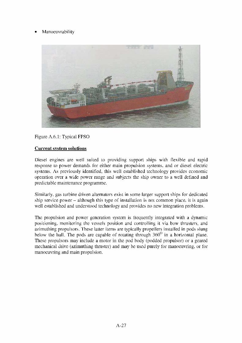
Manoeuvrability
Figure A.6.1: Typical FPSO
Current system solutions
Diesel engines are well suited to providing support ships with flexible and rapid response to power demands for either main propulsion systems, and or diesel electric systems. As previously identified, this well established technology provides economic operation over a wide power range and subjects the ship owner to a well defined and predictable maintenance programme.
Similarly, gas turbine driven alternators exist in some larger support ships for dedicated ship service power - although this type of installation is not common place, it is again well established and understood technology and provides no new integration problems.
The propulsion and power generation system is frequently integrated with a dynamic positioning, monitoring the vessels position and controlling it via bow thrusters, and azimuthing propulsors. These latter items are typically propellers installed in pods slung below the hull. The pods are capable of rotating through 360° in a horizontal plane. These propulsors may include a motor in the pod body (podded propulsor) or a geared mechanical drive (azimuthing thruster) and may be used purely for manoeuvring, or for manoeuvring and main propulsion.
A-27
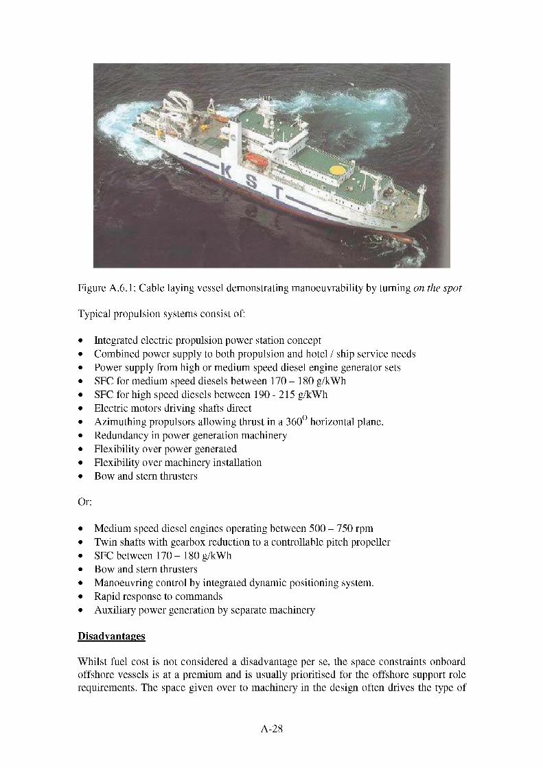
Figure A.6.1: Cable laying vessel demonstrating manoeuvrability by turning on the spot
Typical propulsion systems consist of:
• Integrated electric propulsion power station concept• Combined power supply to both propulsion and hotel / ship service needs• Power supply from high or medium speed diesel engine generator sets• SFC for medium speed diesels between 170 - 180 g/kWh• SFC for high speed diesels between 190-215 g/kWh• Electric motors driving shafts direct• Azimuthing propulsors allowing thrust in a 360° horizontal plane.• Redundancy in power generation machinery• Flexibility over power generated• Flexibility over machinery installation• Bow and stern thrusters
Or:
• Medium speed diesel engines operating between 500 - 750 rpm• Twin shafts with gearbox reduction to a controllable pitch propeller• SFC between 170 - 180 g/kWh• Bow and stern thrusters• Manoeuvring control by integrated dynamic positioning system.• Rapid response to commands• Auxiliary power generation by separate machinery
Disadvantages
Whilst fuel cost is not considered a disadvantage per se, the space constraints onboard offshore vessels is at a premium and is usually prioritised for the offshore support role requirements. The space given over to machinery in the design often drives the type of
A-28

engines selected. Consequently these may not be the most efficient options. Additionally, the limited space reduces options for improving system efficiency through heat recovery or similar methods.
The emissions from medium and high-speed diesels, whilst better than slow speed diesels, are still vulnerable to future increases ion legislation, particularly those governing coastal or inland waterways and ports. The MARPOL emissions requirements are regulated by engine speed, so the improved performance is offset by tighter targets. Additionally those vessels operating on HFO are vulnerable to reduced SOx emission targets. Offshore support vessels are frequently called on to operate in environmentally sensitive areas such as the North Sea, so they are likely to be some of the first types of ships to experience increased environmental legislation targets.
The combination of a wide variety of propulsion and hotel loads required down to the minimum power, dictate a complex propulsion and power generation system. For an electric power plant, this typically consists of a large number of generating sets, with an associated high purchase and running cost. Where mechanically driven shaftlines are used then there is a great danger that the propulsion engines will be run at uneconomic and detrimental loading, whilst a separate power generation plant provides the significant requirements of the hotel load
The penalties for down time in the offshore industry are extreme, especially if it results in reduced or stopped production. It is important that availability of equipment and ships remains high and that time is not lost due to equipment failures that reduce the vessel's capability. This risk is mitigated by selecting proven reliable equipment and usually having some degree of redundancy. Redundancy equates to additional (unneeded) capacity, available in the case of a fault elsewhere. Obviously, using redundant designs leads to increased cost so there is a continuing drive to improve equipment reliability further.
A-29

A.7 LEISURE CRAFT
Introduction
The number of privately owned motor boats is perceived to have been steadily growing for many years, in the UK, visible by the expansion of numerous marinas and private boatyards, particularly on the south coast. The demands users place on such boats is often sporadic and the accompanying usage factor for such leisure craft is comparable to that of domestic motor vehicles.
Issues such as economy and noxious emissions are perceived to be far less important on privately owned leisure boats, as the boat is intended to provide entertainment to the user, and the cost of intermittent and inefficient operation is negligible when compared to the cost of ownership.
Figure A.7.1: Typical luxury day cmiser
Such leisure boats can be further sub-divided into two categories:
1. Displacement craft• Day cruisers• Private fishing boats• Diving boats• Long boats
2. Planing craft• Speedboats• Rigid inflatable boats (RIB)
A-30

• Powerboats
Propulsion system requirements and solutions
For slow speed displacement leisure craft, the prime mover is typically minuscule in comparison to large commercial ships, and will follow a rapidly fluctuating, but low intensity work profile. Currently either an outboard petrol engine, or an inboard petrol or diesel engine may be used (typically automotive derivative engines); for an inboard installations this may well include a power take off driven alternator. Typically, outboard systems require extra power generation plant or batteries where necessary.
In high-speed leisure craft, the requirement to achieve planing condition is common, requiring more power to exceed the resistance hump, and a more robust propulsion system to withstand the increased structural loading. Indeed in powerboats and cruisers, the noise of the engine constitutes part of the enjoyment. The working profile is likely to fluctuate largely with a quick response to load changes. Currently, such boats are powered by high speed petrol or diesel engines, together with a form of high speed propulsor. Propulsion for high speed boats is typically highly loaded and is required to withstand significant pounding and shock loading as a result of its operation. This must in part be transmitted to the prime mover whether through reduction gearing or structurally.
Leisure boats have quite unique propulsion system requirements:
• Reliable operation at random intervals• Quick, uncomplicated start up and shut down• Very high power density in prime movers• Sustained periods of no use• Safe operation
Usual propulsion systems consist of:
• High speed diesel engines >1500 rpm• High speed petrol engines >1500 rpm• Small gas turbines• Driving high speed propulsors, waterjets, surface piercing or supercavitating
propellers• Rapid response to throttle controls• Reversing gearboxes.
Disadvantages
The propulsion systems used are typically optimised for high performance and low volume. The design trade off usually results in a fuel penalty being imposed. This tends to be lass of an issue than for other craft as the utility of leisure craft tend to be relatively
A-31

low and the design and procurement costs are high in the first instance. There is a degree of acceptance that operating craft of this nature will also be expensive.
The optimisation of the propulsion system for high speed typically results in poor part load performance, both in terms of further increase in fuel coat and potentially detrimental running of the engines (leading to increased maintenance loads). The maintenance issue is further hampered by the typically small machinery spaces, which offer a poor working environment for maintenance activities.
A-32

A.8 TOURIST CRAFT
Introduction
Tourist vessels include marine vehicles used for sightseeing, water taxis, or commercial entertainment. Ships for this purpose may only be seasonally operational, but may experience a high usage factor during this time. This clearly has fundamental implications regarding design criteria for the prime movers and their performance, although it should be understood that vessels in this category exist in a huge variation of sizes, shapes and speeds, obviously reflected in the nature of the propulsion system employed.
Propulsion system requirements and solutions
Tourist and pleasure craft are typically very simplistic boats, as their sole purpose is to transport people for short duration in a comfortable manner without the necessity for accommodation, catering, or any services other than the base essentials. Passenger comfort is a key issue hence the absence of noise, fumes or vibration is highly desirable. The seasonal activity of such craft requires maintenance to be limited when operational, with considerable time for overhaul off season; reliability is clearly important.
Typically, inboard petrol or diesel engines power these tourist vessels, through a simple shafting arrangement with low system complexity. Auxiliary power may be provided by power take off or separate machinery, but the overall power requirements are low as there are few services to supply.
Tourist craft require from the propulsion system:
• Economic operation• Good reliability• High power density• Low noise, emissions and vibrations to structure and environment• Low emissions• Response to long periods of non use
Propulsion systems typically consist of:
• High speed diesel or petrol engines• Fixed pitch propellers driven through reduction gearing• Rapid response to throttle control• Reversing gearboxes.
Disadvantages
Tourist vessels tend to operate on a commercial basis and consequently fuel consumption can be very important. Conversely the size of typical tourist vessels and the requirement to carry as many passengers as is feasible and safe reduces the space
A-33

available for machinery and so small high speed ~(and less efficient) engines are required.
There is also minimal space for installing the sorts of complicated systems used on large vessels to deal with a varied power demand. The relatively high amount of time tourist vessels spend manoeuvring or travelling slowly means that the engines are likely to see a significant period of light loading and high cyclic loading. Both of these scenarios have a detrimental effect on the condition and life of the engine. The likely high maintenance load is further hampered by the typically small machinery spaces, which offer a poor working environment for maintenance activities.
Most of these vessels operate in inland waterways and rivers and are vulnerable to future increases ion legislation, particularly those governing coastal or inland waterways and ports. Tourist vessels are also subject to public scrutiny as they are often within view of the shoreline or are seen entering or leaving coastal towns. Consequently an emphasis on low or no smoke or particulate emission is placed on these vessels.
A-34

B.1 TYPICAL SLOW SPEED DIESEL ENGINE SYSTEM
Description
The system boundary includes a slow speed diesel engine, air start system, fuel purification and transfer, lubricating oil purification and transfer, cooling system and heat exchanger, exhaust ducting, exhaust gas boiler and silencer, shaft generator, propeller shaft, shaft bearings and fixed pitch propeller.
It has been assumed that the slow speed diesel drives the propeller shaft directly, rather than via a gearbox and the shaft generator, typical of such as system, has been neglected. The first assumption reflects the high efficiency of a gearbox operating for the majority of its life at or around its design point. Additionally, where a diesel engine’s speed is equivalent to the desired propeller speed, it is possible that the engine will drive the shaft directly [1]. The second assumption has been adopted to simplify the assessment. It should be borne in mind however, that the inclusion of a shaft generator represents a reduction in the power availability of the propeller shaft (typically 15% maximum of the prime mover power) [1] that would be required from any comparable system.
Fuel Consumption
The typical trend for fuel consumption across the power range represented by slow speed diesels is given in the figure below [2].
180
170
^ 160
<2 140
S> 130
120
100
Power Range (MW)
Figure B.1.1: Slow Speed Diesel Engine Specific Fuel Consumption
It can be seen that the specific fuel consumption across the power range follows a fairly even trend between 160 g/kWh and 170 g/kWh. The relatively low specific fuel consumption, based on heavy fuel oil (with a low calorific value) is reflected by the high thermal efficiency (typically in excess of 50%). The fuel consumption figures indicated are typically 10 - 14% lower than medium speed diesels and nearly 20% lower than high-speed diesels.
B-1
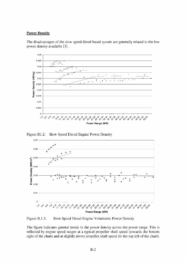
Power Density
The disadvantages of the slow speed diesel based system are generally related to the low power density available [3],
0.045
"S 0.035
'(/> 0.025
0.015
0.005
Power Range (MW)
Figure B1.2: Slow Speed Diesel Engine Power Density
g" 0.05
S- 0.04
Q 0.03
CL 0.02
Power Range (MW)
Figure B.1.3: Slow Speed Diesel Engine Volumetric Power Density
The figure indicates general trends in the power density across the power range. This is reflected by engine speed ranges at a typical propeller shaft speed (towards the bottom right of the chart) and at slightly above propeller shaft speed (to the top left of the chart).
B-2

In either case, the power density is significantly lower than that for other prime movers. The very best slow speed diesels (in terms of power density) are only just approaching the figures for the very worst medium speed diesels and offer less than half the power density of the worst high-speed diesels. In general, slow speed diesels are nearly three times as heavy as medium speed diesels and over four times as heavy as high speed diesels for an equivalent power output. As with the power density derived from the engine weight, the figure indicates two general trends across the power range. Again this is reflected by two basic engine speed ranges one at a typical propeller shaft speed (towards the right of the chart) and one at slightly above propeller shaft speed (to the left of the chart). In either case, the volumetric power density is also lower than that for other prime movers. The very best slow speed diesels (in terms of volumetric power density) are equivalent are even marginally better than the worst medium speed diesels and are approaching the power density of the worst high speed diesels. In general, however, slow speed diesels are nearly twice as big (in terms of volume) as medium speed diesels and over five times as big (in terms of volume) as high speed diesels for an equivalent power output.
System Response
Slow speed diesels generally show a slow response to load changes due to the large reciprocating masses. This makes them unsuitable for applications requiring rapid load changes or responses to power demands. However the typical size of vessels best suited to slow speed diesel are such that a rapid response by the propulsion system would be negated by the damping effect of the ship’s extremely high inertia. This dictates a requirement for tug assistance when entering and leaving berths or busy waters.
Environmental Issues
Currently the NOX emissions from the modern generation of slow speed diesel engines will be below the levels required by MARPOL Annex VI. Research is being conducted across the industry on technologies for meeting any future reduction in NOX emissions, either by fuel pre treatment, on engine techniques or exhaust treatment. Further tightening of legislation, or the need to meet more stringent none marine-specific legislation, is likely to require the inclusion of these technologies. The requirements for SOX reduction do raise potential problems for the slow speed diesel market. SOX reduction will most likely be achieved by reducing the sulphur content of the fuel used. The additional cost using higher-grade fuel or of pre treating the fuel may possibly tip the economic balance of current slow speed diesel installations.
Economics of the Slow Speed Diesel System
Slow speed diesel engines systems remain the system of choice for long distance shipping. This is due to the high power output, low fuel consumption of the engines, good system efficiency and cheap fuel that can be burnt in the engine. These savings outweigh the cost, in terms of reduced cargo, represented by the larger volume of the prime mover. The low speed diesel system also demonstrates good reliability, essential as the large vessels that utilise this sort of system spend long periods at sea, away from
B-3

shore side support facilities and undertake their voyages using a single engine, shaft and propeller.
Typical installed costs are between 140 to 200 £/kW.
Auxiliary Power Generation
As mentioned earlier, the generally steady speed operation of the slow speed diesel propulsion system makes it ideal for a shaft generator. Typically the shaft generator is driven off the propeller shaft or the engine’s power take-off and will supply the majority of the electrical power required for the vessel. Vessels will typically have diesel driven auxiliary generation plant to supplement the shaft generator, or for use whilst alongside or at anchor.
Auxiliary System Characteristics
Slow speed diesel engines are designed to burn heavy fuel oil (HFO). This has an economic benefit, as it is cheaper than marine diesel oil (MDO) or distillate fuel, though is a more harmful substance to health and to the environment. The fuel requires heating prior to delivery, to assist fuel flow through the pipework. This may be achieved by electrical or steam heating. The fuel is also centrifuged prior to use to remove the heavier sludge and impurities contained.
The fuel system transfers oil from bunker tanks, via centrifuges, to settling tanks, then to service tanks (with additional centrifuging if required) and thus to the engine. The fuel will require pre heating to improve the flow characteristics of the oil through the system. Fuel pumps, required for each stage of the process are typically installed in tandem to offer redundancy in the case of pump failure, or to allow continued operation during pump maintenance. Residue from the centrifuges is transported to either a waste oil or oily sludge tank.
The lubricating oil system transfers oil from the bulk storage tank, via centrifuges, to a service tank and then to the engine. In the engine, the lubricating oil is used for cooling bearing surfaces; the heat generated is removed from the oil via the lubricating oil cooler heat exchanger. As with the fuel system, the oil requires pre heating to improve the flow through the system. Lubricating oil pumps are installed in tandem to offer redundancy in the case of pump failure, or to allow continued operation during pump maintenance. Residue from the centrifuges is transported to either a waste oil or oily sludge tank.
Typical lubricating oil consumption ranges from 0.8 - 1.5 5/kWh for the cylinder lubricating oil. Lubricating system oil, supplying bearings, camshafts etc. is consumed at a rate of between 0.04 to 0.5 kg/hour, per cylinder, depending on the engine size (and speed).
If the bunker and other tanks required for the systems are excluded, then the volume and weight of the fuel or lubricating oil transfer and treatment system is negligible when
B-4

compared to the actual engine itself. Tankage for the lubricating oil system is generally not large compared to that required for fuel oil. The fuel oil bunkers themselves are heavily dependent on the voyages the ship undertakes and the speed at which they are undertaken. Typically, large ships with slow speed diesels have heavy oil bunkerage in the range of 2000 to 8000 m3, with a consumption of between 40 and 70 tonnes / day.
Cooling of the engine block is generally achieved by a closed loop fresh water circuit, which in turn is cooled by an open sea water circuit. The lubricating oil is also usually cooled by an open sea water circuit. The jacket water cooling system in the engine block is also used to pre-heat the engine, prior to starting. This is achieved by heating the cooling water to between 50 and 90O C either electrically, using steam heating or by using heated cooling water from another source (e.g. auxiliary engines).
Combustion air is generally supplied direct from the machinery spaces with no dedicated system. However all air taken from the space must be replaced, either by natural or forced draught.
The exhaust system transfers the combustion gases from the engine to atmosphere, via a silencer / spark arrester and exhaust gas boiler. The exhaust gas boiler recovers heat from the exhaust gases and uses it to generate steam (for heating or turbo generation) or fresh water. This effectively increases the overall efficiency of the propulsion system. Exhaust gas boilers operate in a harsh environment. The NOX and SOX content of the exhaust makes it very acidic with consequent impacts on boiler life. As emissions legislation becomes more important, exhaust systems are being designed with provision for an after treatment unit to remove NOX (or CO, CO2 etc.).
The quantity of exhaust is directly related to the power output of the engine and the engine speed. The noxious characteristics of the exhaust gases require them to be discharged well away from working areas and upper deck areas, often from a smokestack. The location of the exhaust discharge and the quantity of exhaust discharged will determine the overall size of the system and hence its impact on the ship. Typical exhaust system diameters range from approximately 1m to 2.6m, with a correlation to the maximum continuous rating of the engine. Additional allowance is required for an exhaust gas boiler, silencer and spark arrester, depending on capability.
System Maintenance
Slow speed diesels will remain in situ for the duration of the ship’s life. Maintenance will be done in situ i.e. replacing fuel and oil filters etc. or by removing major components and overhauling or replacing them. The size of the components makes this a serious undertaking requiring a significant amount of space or the undertaking of a large quantity of work in way. This requires space allocation for removal routes to get major components out of the machinery space.
Typical maintenance requirements are given below:
B-5

Component Maintenance Period for Overhaul / (hours)
Piston rings 12000Piston rod stuffing box rings 12000Piston rod stuffing box sealing rings 24000Exhaust valve spindles 36000Exhaust valve O rings 6000Exhaust valve guide bushings 18000Exhaust valve seats 36000Fuel pump roller guide bushings 36000Fuel pump plungers 36000Fuel valve guides and atomisers 18000Turbo charger slide bearings 24000Guide bars for chain drive 36000Bearings for auxiliary blower 24000Table B1.1: Maintenance period for overhaul
Lubricating oil changes and filter changes are often carried out on a condition basis.
Associated Propulsion System Components
The slow speed diesel propulsion system machinery is usually situated in the stern of the vessel, below the accommodation block in the superstructure. Thus the volume required for machinery rooms, air inlet and exhaust ducting does not infringe on the cargo space. Additionally, location of the propulsion machinery in the stern allows the length of the propeller shaft to be minimised with associated savings in cost and efficiency losses.
The short propulsion shaft means that there is a minimal requirement for shaft support and hence shaft bearings. This allows efficiency losses in the propulsion train to be minimised.
The low manoeuvring requirement and the relatively constant speed means that the propulsor of choice is a large diameter fixed pitch propeller, with the blade pitch optimise for the desired transit speed and hull efficiency.
The relatively simple system requires little in the way of additional supporting services. The main requirement is to be supply lubricating oil to the bearings and pressure to ensure a good seal in the stern tube glands, where the propeller shaft exits the hull.
B-6
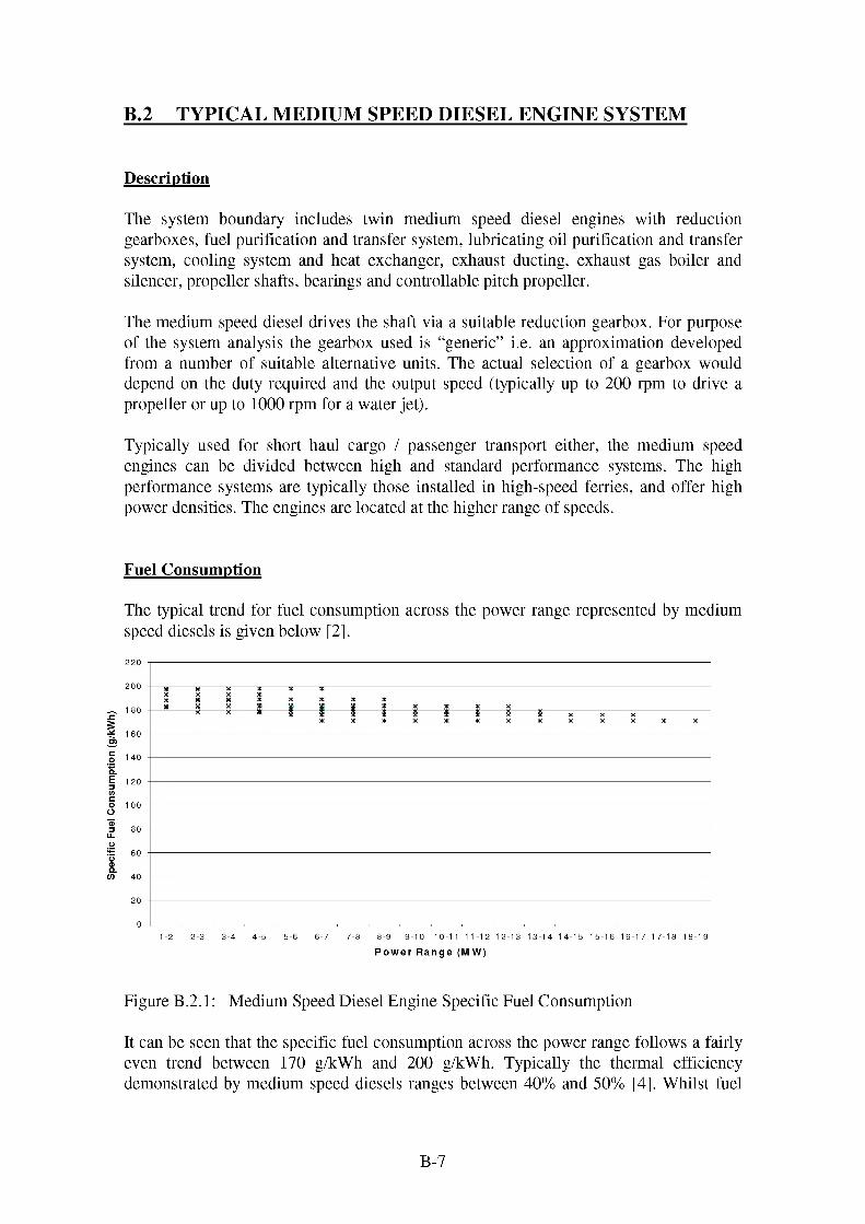
Spec
ific F
uel C
onsu
mpt
ion
(g/k
Wh)
B.2 TYPICAL MEDIUM SPEED DIESEL ENGINE SYSTEM
Description
The system boundary includes twin medium speed diesel engines with reduction gearboxes, fuel purification and transfer system, lubricating oil purification and transfer system, cooling system and heat exchanger, exhaust ducting, exhaust gas boiler and silencer, propeller shafts, bearings and controllable pitch propeller.
The medium speed diesel drives the shaft via a suitable reduction gearbox. For purpose of the system analysis the gearbox used is “generic” i.e. an approximation developed from a number of suitable alternative units. The actual selection of a gearbox would depend on the duty required and the output speed (typically up to 200 rpm to drive a propeller or up to 1000 rpm for a water jet).
Typically used for short haul cargo / passenger transport either, the medium speed engines can be divided between high and standard performance systems. The high performance systems are typically those installed in high-speed ferries, and offer high power densities. The engines are located at the higher range of speeds.
Fuel Consumption
The typical trend for fuel consumption across the power range represented by medium speed diesels is given below [2].
Power Range (MW)
Figure B.2.1: Medium Speed Diesel Engine Specific Fuel Consumption
It can be seen that the specific fuel consumption across the power range follows a fairly even trend between 170 g/kWh and 200 g/kWh. Typically the thermal efficiency demonstrated by medium speed diesels ranges between 40% and 50% [4], Whilst fuel
B-7
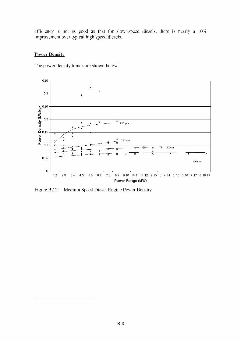
efficiency is not as good as that for slow speed diesels, there is nearly a 10% improvement over typical high speed diesels.
Power Density
The power density trends are shown below6.
0.35
0.3
0.25
0.2900 rpm
0.15
750 rpm
0.1600 rpm
0.05500 rpm
1-2 2-3 3-4 4-5 5-6 6-7 7-8 8-9 9-10 10-11 11-12 12-13 13-14 14-15 15-16 16-17 17-18 18-19
Power Range (MW)
Figure B2.2: Medium Speed Diesel Engine Power Density
B-8

0.3
0.25
900 rpm
500 - 750 rpn
0 -I- - - - - - - - - - - - - - - T- - - - - - - - - - - - - - T- - - - - - - - - - - - - - T- - - - - - - - - - - - - - T- - - - - - - - - - - - - - - T- - - - - - - - - - - - - - T- - - - - - - - - - - - - - T- - - - - - - - - - - - - - T- - - - - - - - - - - - - - - T- - - - - - - - - - - - - - T- - - - - - - - - - - - - - - T- - - - - - - - - - - - - - T- - - - - - - - - - - - - - - T- - - - - - - - - - - - - - T- - - - - - - - - - - - - - T- - - - - - - - - - - - - - T- - - - - - - - - - - - - - T- - - - - - - - - - - - - -
1-2 2-3 3-4 4-5 5-6 6-7 7-8 8-9 9-10 10-11 11-12 12-13 13-14 14-15 15-16 16-17 17-18 18-19
Power Range (MW)
Figure B2.3: Medium Speed Diesel Engine Volumetric Power Density
The figure clearly shows how the power density trends alter with the speed of the engine. The 900 - 1000 rpm medium speed diesels offer the best power density in this range, with performance comparable with many high-speed diesels. This makes them desirable for high-speed applications where space and weight are at a premium. The power density performance of propulsion systems based on these types of engines will be enhanced for water jet systems if a reduction gearbox is not needed. The slower medium speed engines show benefits over the more power dense slow speed diesels and nearly 50% improvements over the bigger slow speed diesel engines. The power density trends established for medium speed diesels in the previous chart are also reflected in the volumetric power density trends. The key difference being the less pronounced differences in the 150 - 500 rpm range (where as the 900 - 1000 rpm engines still show markedly better performance. The slower engines are typically used where space is less critical and maintenance, reliability and fuel consumption become more important.
System Response Time
The lower reciprocating mass of these engines means they often have a rapid response to control signals. This is important in crowded coastal shipping lanes and ports and is also a key benefit for vessels spending a relatively large proportion of their time manoeuvring, rather than steady steaming. This may offer a significant benefit in life cycle costing, if tug assistance is not required for berthing / manoeuvring.
Environmental Issues
As a general rule, medium speed engines emit lower quantities of NO% than slow speed diesels; a trend recognised in the forthcoming MARPOL Annex VI regulations. The vast majority (if not all) current medium speed engines will fulfil the requirements of this
B-9

Annex without any additional features. Further tightening of NOX legislation can be met by either by fuel pre treatment, on engine techniques or exhaust treatment. Depending on the application, medium speed engines may run on HFO or MDO. Engines running on HFO will face the same problems of sulphur content of fuel as slow speed diesels. The higher quality (including lower sulphur content) of MDO will probably not be affected in the immediate future by SOx requirements.
Economics of the medium speed diesel system
Where there is insufficient space to install a slow speed diesel, or where a more rapid response to load changes is required, medium speed diesels tend to be selected. They offer good fuel consumption and reliability whilst being significantly more compact than a slow speed diesel. This compactness allows premium space, for cargo or passengers, to be made available. In addition, medium speed diesels can generally be run on either HFO or MDO. Consequently, medium speed diesels offer a compromise between a number of design drivers for the propulsion system.
The higher speed range of the medium speed sector (900 rpm - 1000 rpm) offers some specialist features. These engines tend to be high performance models offering notably improved power to weight ratios over other medium speed diesel engines. Indeed the power to weight ratio of this group rivals that of the high-speed diesel sector, but generally at significantly higher powers. This has made such engines the preferred option for the fast ferry market, where vessel displacement becomes critical.
The typical price range for medium speed diesels ranges from 100 to 200 £/kW. The specific price tends to increase as the power requirement increases.
Auxiliary Power Generation
The mode of auxiliary power generation depends on the operation of the vessel concerned. Where engines can be relied upon to run at a constant speed for the majority of the time, then shaft generators may be employed. The nature of many of the users of medium speed diesels includes significantly fluctuating propulsion loads. Such applications are likely to rely on a separate set of auxiliary generators.
Auxiliary System Characteristics
Medium speed diesel engines are designed to burn either HFO or MDO. HFO has an economic benefit as it is cheaper than MDO or distillate fuel, though is a more harmful substance to health and to the environment. Either way, the fuel requires pre treatment to remove impurities. Shorthaul vessels will generally use fuel that has been pre-treated ashore, whilst long haul vessels will treat their fuel onboard.
The fuel system transfers oil from bunker tanks, via centrifuges (if fuel is not pre-treated prior to embarkation), to settling tanks, then to service tanks (with additional centrifuging if required) and thus to the engine. The fuel will require pre heating to
B-10

improve the flow characteristics of the oil through the system. Fuel pumps, required for each stage of the process are typically installed in tandem to offer redundancy in the case of pump failure, or to allow continued operation during pump maintenance. Residue from the centrifuges is transported to either a waste oil or oily sludge tank.
The lubricating oil system transfers oil from the bulk storage tank, via centrifuges, to a service tank and then to the engine. In the engine, the lubricating oil is used for cooling bearing surfaces; the heat generated is removed from the oil via the lubricating oil cooler heat exchanger. As with the fuel system, the oil requires pre heating to improve the flow through the system. Lubricating oil pumps are installed in tandem to offer redundancy in the case of pump failure, or to allow continued operation during pump maintenance. Residue from the centrifuges is transported to either a waste oil or oily sludge tank. Typical lubricating oil consumption is between 0.5 and 1 g/kWh, which may not sound significant, but represents between one and two tonnes of oil for an 8 MW propulsion engine at full power for a 10 day journey.
If the bunker and other tanks required for the systems are excluded, then the volume and weight of the fuel or lubricating oil transfer and treatment system is negligible when compared to the actual engine itself. The required bunkerage for a medium speed diesel system depends very heavily on the ship type. The wide variety of ships that are powered by medium speed diesels is reflected in the wide range of bunker capacities. These may vary from 124 m3, for a short haul ferry with a consumption of 15 tonnes / day to 3000 m3 for a large cruise liner with a consumption of nearly 200 tonnes / day.
In addition to lubricating oil cooling of bearing surfaces the engines have fresh water cooling circuits to extract heat from the engine block, cylinder heads, cylinders and pistons. Fresh water circulates in a closed loop through galleries in the engine block and out of the engine to one or more sea water cooled heat exchangers. From the discharge of the heat exchange the fresh water is lead back to the engine. Sea water is generally supplied from the main sea water cooling system, drawing directly from the sea and is discharged overboard.
The dual circuit system takes up a reasonably large amount of space, maybe an additional 25% of the bulk of the engine.
Combustion air is generally supplied direct from the machinery spaces with no dedicated system. However all air taken from the space must be replaced, either by natural or forced draught.
The exhaust system transfer the combustion gases from the engine to atmosphere, via a silencer / spark arrester. Where economic to do so, an exhaust gas boiler may be included, to recover heat from the exhaust gases and uses it to generate steam (for heating or turbo generation) or fresh water. This effectively increases the overall efficiency of the propulsion system. Exhaust gas boilers operate in a harsh environment. The NOX and SOX content of the exhaust makes it very acidic with consequent impacts on boiler life. However, the lower levels of NOX and SOX emitted by engines burning MDO reflect an increase in typical boiler life. As emissions legislation becomes more important, exhaust systems are being designed with provision for an after treatment unit to remove NOX (or CO, CO2 etc.).
B-11

The quantity of exhaust is directly related to the power output of the engine and the engine speed. The noxious characteristics of the exhaust gases require them to be discharged well away from working areas and upper deck areas, often from a smokestack. The location of the exhaust discharge and the quantity of exhaust discharged will determine the overall size of the system and hence its impact on the ship.
The volume of the exhaust gas system is directly related to the power output and location of the engine. For reasons of economy of manufacture however, the diameter of the exhaust gas pipework tends to be incremental (typically metric), from approximately 400 mm to 700 mm. The length required is dependent on the relative locations of the engines and exhaust discharge and is heavily influenced by the ship type. Additional volume is required for any silencers, exhaust gas boilers or exhaust treatment units.
Starting the engine is typically achieved by blowing compressed air directly into the cylinders. The Classification Societies, who regulate the shipping industry (e.g. Lloyds Register of Shipping, American Bureau of Shipping, etc.) require 6 consecutive starts for non-reversing engines. Typically the starting air system will have two air receivers at about 30 bar, charged by at least two compressors. Typical volumes of the air receivers vary from between 0.125 and 1 m3. Starting time is typically measured in seconds.
The actual volume of the auxiliary systems is heavily dependent on the engine type and size, and the vessel arrangement. Additionally, many of the auxiliary systems serve multiple users, not simply the propulsion / power generation system. For instance, steam may be use for pre heating fuel, but is also often required for compartment heating. Compressed air is used for engine start, but also for system control (albeit in smaller quantities). Additionally, the systems can not be packed in, as maintenance access is required for both the system components and the actual prime movers themselves. Consequently, judging the volume and weight of the auxiliary requirements is not straightforward. However, based on a typical engine room floor plan, it is not impossible that the auxiliary systems may represent anywhere between 30 and 50% of the available space.
System Maintenance
Medium speed diesels are generally designed to remain in place for the duration of the ship’s life. However severe maintenance problems can be rectified by replacing the whole engine. Generally, maintenance will be done in situ i.e. replacing fuel and oil filters etc. or by removing major components and overhauling or replacing them. This requires space allocation for removal routes to get major components out of the machinery space.
Typical major maintenance tasks and hourly intervals are given below:
B-12

Component Fuel Maintenance Period for
Overhaul / (hours)
Expected Life /
(hours)
Task Length (hours)
Piston MDO 20000 40000 4 - 10HFO 12000 24000
Piston rings MDO 20000 20000 4 - 10HFO 12000 12000
Cylinderliner
MDO 20000 60000 4 - 10HFO 12000 60000
Cylinderhead
MDO 20000 60000 4HFO 12000 60000
Inlet valve MDO 20000 40000 4HFO 12000 24000
Exhaustvalve
MDO 20000 24000 4HFO 12000 12000
Injection valve nozzle
MDO 2000 8000 2 - 3HFO 2000 4000
Injectionpump
MDO 16000 32000 1 - 3HFO 16000 16000
Main bearing MDO 16000 32000 3 - 4HFO 16000 32000
Big end bearing
MDO 20000 20000 2 - 3HFO 12000 12000
Replaceturbocharger
Unscheduled 12
Table B2.1: Maintenance for a typical medium speed diesel engine
Lubricating oil changes and filter changes are often carried out on an oil condition basis.
Associated Propulsion System Components
The location of the machinery spaces for typical medium speed diesel engine systems depends on the type of ship. Pure cargo vessels will typically have machinery spaces located aft, whereas research vessels or offshore support vessels, requiring working decks aft, will have machinery spaces further forward, to allow exhaust ducts to be routed clear of the working decks.
Consequently propeller shafts can vary in length. This length dictates the requirement (in terms of numbers) for shaft supporting bearings and hence the efficiency losses through the propeller shaft. However, the bearing losses tend to be very small.
These systems are often required to undertake a significant amount of manoeuvring operations. This is often achieved with a controllable pitch propeller, where the power into the water can be fine tuned by varying the propeller blade angle. These devices also allow reverse thrust to be generated without reversing the direction of the shaft rotation. Whilst fixed pitch propellers offer a better efficiency at their design point, a controllable
B-13

pitch propeller offers a wider range of efficient operating points, ideal for vessels with a varied operating profile.
The relatively simple system requires little in the way of additional supporting services. The main requirement is to supply lubricating oil to the bearings and gearbox, pressure to ensure a good seal in the stern tube glands, where the propeller shaft exits the hull and hydraulic oil to the controllable pitch propeller actuators.
B-14

Spec
ific F
uel C
onsu
mpt
ion
(g/k
Wh)
B.3 TYPICAL HIGH SPEED DIESEL ENGINE SYSTEM
The system boundary includes a high speed diesel engine, reversing / reduction gearbox, fuel and lubricating oil transfer system, cooling system, heat exchanger, exhaust ducting and silencer.
The high speed diesel drives the shaft via a suitable reduction gearbox. For purpose of the system analysis the gearbox used is “generic” i.e. an approximation developed from a number of suitable alternative units. The actual selection of a gearbox would depend on the duty required and the output speed (typically up to 350 rpm to drive a conventional or high speed propeller or up to 1500 rpm for a water jet).
Typically used for high speed, short haul passenger transport or other applications where space and weight are critical (small craft, yachts etc.), or for auxiliary generation, the high-speed diesels prime advantage is power density. Many high speed engines are automotive derivatives with additional features to allow operation in the harsh marine environment. This makes them relatively easy to support in terms of spares and after sales service, reflecting the market they are aimed at.
Fuel Consumption
The typical trend for fuel consumption across the power range represented by highspeed diesels is given below.
750-1000 1000-1250 1250-1500 1500-1750 1750-2000 2000-2250 2250-2500 2500-2750 2750-30000-250 250-500 500-750
Power Range (kW)
Figure B.3.1: High Speed Diesel Engine Specific Fuel Consumption
B-15

The relatively high fuel consumption and the fact that two significantly different trends are evident reflect the fact that the market for these diesels is not driven primarily by fuel economy.
The fuel consumption is typically 25% greater than that for slow speed diesels and approximately 15 - 20% greater than medium speed diesels. As can also be seen the power requirements are typically much lower than other classes of diesels, though the larger units do overlap with the smaller medium speed diesels.
Power Density
The prime advantage for high-speed diesels over other engines is the high power density that is available. The figures below indicate typical values for a variety of engines.
0.35
0.25
Q 0.15
0.05
0-250 250-500 500-750 750-1000 1000-1250 1250-1500 1500-1750 1750-2000 2000-2250 2250-2500 2500-2750 2750-3000
Power Range (kW)
Figure B.3.2: High Speed Diesel Engine Specific Power Density
B-16

0-250 250-500 500-750 750-1000 1000-1250 1250-1500 1500-1750 1750-2000 2000-2250 2250-2500 2500-2750 2750-3000
Power Range (kW)
Figure B.3.3: High Speed Diesel Volumetric Power Density
These figures show trends that generally increase with power for a variety of engines. As an indication of the levels of performance, specific power density for high speed diesels is some ten times that for slow speed diesels. The worst of the high speed diesels is roughly equivalent, in terms of specific power density, to the 500 - 750 rpm medium speed diesels. If equivalent powers are compared however, then the power density of a high speed diesel is typically twice that of a medium speed diesel (excluding the high performance 900 - 1000 rpm diesels).
System Response Time
High speed diesel engines can exhibit rapid response times, though the high reciprocating / rotating speeds involved do require time to run down. This is important, as the vessels powered by these engines tend to operate in crowded harbours or waterways and also tend to run on random routings, and operating cycles (at owner’s whim), rather than repetitive predefined routes and cycles. The vessels will also spend a disproportionate amount of time conducting manoeuvring or similar operations, compared to other types of vessel.
Environmental issues
The rapid combustion in the cylinders of high-speed diesels means that there is a limited period to allow the formation of NO%. As a general rule, the faster the engine the lower the NOx levels in the exhaust. Consequently it is anticipated that high-speed diesels will be least affected by future tightening of NOx legislation. In addition these engines tend to run on high quality distillate fuel with a low sulphur content. Consequently they are also less vulnerable to tightening of SOx limits.
B-17

Economics of the high speed diesel system
High-speed diesels are selected when space, and hence power density, is at a premium. The fuel consumption offered is high compared to other diesels, but the power to weight and power to volume ratios are excellent. This makes then ideal for small vessels where space is limited, or fast vessels where weight reduction is the driving factor. High-speed diesels also demonstrate very rapid response to fluctuating loads and are often easy to support. The latter point makes them a good option for small scale operators with a limited (or no) service and support facility.
Auxiliary Power Generation
Auxiliary power generation for high speed diesel systems is usually achieved using small, high-speed, diesel generators. Use of shaft generators is not feasible as the fluctuation of loading typically experienced, translates to a fluctuation in shaft speed with consequent problems for synchronisation of any electrical power generated.
Auxiliary System Characteristics
The shorthaul nature of the majority of high speed diesel applications, and the associated space and weight constraints, means that they tend to use fuel that has been pre-treated ashore. This means that the fuel system is straight forward, relying on fuel transfer pumps from bulk storage to ready use tanks, with little requirement to clean up the fuel (typically coalescing filters are used to remove any moisture and sediment). Consequently the size of the fuel transfer system is minimal. However, the use of pre treated fuel increases the fuel costs of high speed diesels further.
Pre treated lubricating oil is also used, for the same reasons as expressed above. The lubricating oil system would generally consist of a single ready use tank with pumped or gravity fed supply to the engine. A sea water lubricating oil cooler is likely to be required thought the smaller engines may be able to dissipate the heat in the lubricating oil using an air cooling or some other more compact means.
Generally the size and weight of the fuel and lubricating oil systems will be minimised. Typical lubricating oil consumption varies from 0.4 to 0.6 g/kWh.
In preference the combustion air would be drawn directly from outside the engine room, to reduce the likelihood of impurities. This is also of benefit to smaller vessels that may have insufficient volume in the machinery space to allow air to be drawn direct from the space. The quantity of air required is small, so it is unlikely that the impact on the ship of the combustion air system would be significant.
The small size and power of most high speed diesels means that the exhaust system is generally simple. Exhaust is ducted away from the engine, via a silencer / spark arrester to atmosphere or for some ferry applications underwater. The small size of these engines means that it easier to disperse the exhaust gases generated and consequently the exhaust is not required to discharge so high up in the ship. As before the gases should be
B-18

exhausted clear of any working spaces or upper deck areas. The vast range of power ratings for this class of engine has a correspondingly large range of exhaust systems. Typically the exhaust diameter will be less than 450 mm.
Staring the engine may be achieved by air, hydraulic or electric start. The Classification Societies require 6 consecutive starts to be available in stored form, either compressed air, hydraulic accumulators or batteries. Starting air capacity is typically less than 0.5 m3 at 30 - 40 bar, but can be reduced if higher storage pressures are used. This is typically driven by the available space in the vessel.
The actual volume of the auxiliary systems is heavily dependent on the engine type and size, and the vessel arrangement. Many of the high-speed diesel applications have very tight space constraints, so the auxiliary systems tend to very compact and simple. Based on a typical engine room floor plan, it is not impossible that the auxiliary systems may represent anywhere between 10 and 25% of the available space.
System Maintenance
High-speed engines are typically maintained in terms of top end or major overhauls. A top end overhaul involves the removal of the cylinder head and inspection of the timing gear, cylinders, pistons, piston rings valves and sealings etc. Components are replaced as deemed necessary, on condition or life expiry. A major overhaul usually involves stripping the engine to a state to be able to inspect the crankshaft bearings and big end bearings. This may be done in situ or subsequent to the engine being removed.
Recommended periods for top end and major overhauls typically depend on the engine speed, operating profile and hence wear rate, but may be after 5000 - 10000 and 12000 - 20000 hours respectively. Oil and lubricating oil changes may be required as frequently as every 250 hours.
B-19

Component Maintenance Period for Overhaul / (hours)
Task Length (hours)
Replace oil & filter 250 - 500 1.5Replace fuel filter 250 - 1000 1.5Maintain sea water pump 250 - 500 2Engine top end (cylinder head, liners pistons and valve / timing gear) overhaul
5000 - 10000 Variable - heavily dependent on the size of the engine
Complete overhaul 12000 - 2000 Variable - heavily dependent on the size of the engine
Table B3.1: Maintenance requirements for a typical high speed diesel
Typical diesel MTBF in excess of 4000 hoursMTBO 2000 - 12000
As a general rule, manufacturers quote the following maintenance requirements:
1.5 - 2 hours maintenance required weekly (every week)2 - 2.5 hours maintenance required every week 250 running hours 15 - 20 hours maintenance required every week 1500 running hours 18 - 25 hours maintenance required every week 6000 running hours
Please note that the each of the hours accumulations is effectively a service period and that they should be thought of as cumulative. So 6000 hour service also requires the time for 1500 hour tasks etc. to be added to it.
Actual task lengths vary between engine types and degree of maintenance friendly features. Often newer engines offer reduced maintenance task lengths. High speed diesel maintenance tends to be on an overhaul basis rather than in situ stripping and replacement of components. Also high speed engines are smaller and more compact therefore easier to remove for overhaul ashore. This is analogous to the automotive industry where minor work may be carried out with the engine in place, and tends to focus on the replacement of consumables. Major maintenance may need the removal of the engine (and possibly replacement in the meantime) and servicing at an approved dealer / workshop.
B-20
Associated Propulsion System Components
The high speed diesel system typically drives through a reduction/reversing gearbox to a fixed pitch propeller. The relatively simple system requires little in the way of additional supporting services. The main requirement is to be supply lubricating oil to the bearings and gearbox and pressure to the stern tube glands to ensure a good seal, where the propeller shaft exits the hull.
For high (ship) speed applications, the diesel will probably drive a waterjet via a reduction gearbox. Waterjets, like controllable pitch propellers, are able to generate reverse thrust without the need to reverse the direction of the propeller shaft. The main auxiliary requirements are to supply lubricating oil to the bearings and gearbox and pressure to ensure a good seal in the stern tube glands, where the propeller shaft exits the hull. Typical waterjet packages come complete with their own auxiliary hydraulic package for controlling the thrust generated and the direction of the thrust (including reversing mechanism).
References
[1] Based on data and information contained in MAN B&W two stroke diesel engine project guides.
[2] Figures from manufacturers’ data and from “Diesel Directory 2000” published by Marine Engineering Review.
[3] Jane’s Marine Propulsion 1999
[4] Marine Engineering Review November 1996.
B-21

B.4 TYPICAL SIMPLE CYCLE GAS TURBINE SYSTEM
The system boundary includes a simple cycle gas turbine and enclosure, reduction gearbox, fuel purification and transfer module, lubricating oil purification and transfer module, cooling system and heat exchanger, uptake (exhaust) and downtake (combustion air) ducting. The gas turbine may drive a controllable pitch propeller or a waterjet, depending on application.
The gas turbine drives the shaft via a suitable reduction gearbox. For purpose of the system analysis the gearbox used is “generic” i.e. an approximation developed from a number of suitable alternative units. The actual selection of a gearbox would depend on the duty required and the output speed (typically up to 350 rpm to drive a conventional or high speed propeller or up to 1500 rpm for a water jet). The fuel treatment system uses centrifuges to provide the high standard of fuel required for most marine gas turbine.
Fuel Consumption
Typically used for high speed, short haul passenger transport, other applications where space and weight are critical, or for the provision of high power requirements. The specific fuel consumption of a typical marine gas turbine is substantially higher than that for a marine diesel. Typical values of fuel consumption are shown below:Figure B.4.1: Specific Fuel Consumption for Generic Simple Cycle Gas
0.35
°.25
0.05
10% 20% 30% 40% 50% 60% 70% 80% 90% 100%
Load
Turbines
The figure shows a plot of specific fuel consumption against percentage power rating for a number of engines. The resultant curve is typical of the fuel consumption figures of a gas turbine and highlights the disadvantages, in terms of fuel consumption, of part load running of these engines. It should also be noted that even at the most efficient point, the
B-22

Pow
er D
ensi
ty (k
W/k
g)gas turbine fuel consumption is typically 10% higher than an equivalent diesel engine. The chart also shows the good correlation between %age power and fuel consumption for a number of engines. This is a better representation for gas turbines than the fuel consumption / power output correlation of the diesel engines.
Power Density
The relatively high fuel consumption is compensated for by the extremely good power density. The figures show the power density of typical marine gas turbines:
1.4
1.2
1
0.8
0.6
0.4
0.2
0
KC D G H J
Example Engine
Figure B.4.2: Power Density of Typical Marine Gas Turbines
The charts do not give any specific trends against power, as little correlation was shown, but do indicate that typical power densities lie between 0.2 and 1.4 MW/tonne and 0.1 and 0.6 MW/m3. Only the higher speed medium speed diesels and the high speed diesels match these levels of performance.
The difference is even more marked at the higher power ranges. Here typical power density figures of 0.2 - 0.3 MW/tonne and 0.1 - 0.2 MW/m3 are a factor of 10 better than slow speed diesels and twice as good as the slower medium speed diesels, the only diesel contenders in the 10 MW+ market
B-23

0.6
x x
0C D E F G H I J K
Example Engine
F igure B.4.3: Volumetric Power Density of Typical Marine Gas Turbines
The charts do not give any specific trends against power, as little correlation was shown, but do indicate that typical power densities lie between 0.2 and 1.4 MW/tonne and 0.1 and 0.6 MW/m3. Only the higher speed medium speed diesels and the high speed diesels match these levels of performance. The difference is even more marked at the higher power ranges, where typical power densities of 0.2 - 0.3 MW/tonne and 0.1 - 0.2 MW/m3 are a factor of 10 better than slow speed diesels and twice as good as the slower medium speed diesels, the only diesel contenders in the 10 MW+ market.
System Response Time
Gas turbines generally show a rapid response due to their low rotating masses. This makes them well suited for applications requiring rapid load changes or responses to power demands.
Environmental issues
The NOx emissions performance required by MARPOL Annex VI is applicable to marine diesel engines, but not gas turbines (as yet). However localised legislation such as that in force in Scandinavia, USA or that proposed by the EU, is likely to be blanket across all prime movers. Bearing this in mind, an increasingly important benefit offered by gas turbines is low NOx emissions, compared to diesel engines. This is mainly due to the high grade fuel (distillate) generally required for gas turbines; SOx emissions are unlikely to be a problem and low NOx level can be easier achieved when compared to diesels. Further tightening of emissions legislation will have a greater impact on diesel engines than gas turbines. However if gas turbine specific legislation is introduced, this situation may later. Future legislation controlling CO2 emissions would affect gas turbines, potentially severely.
B-24

Economics of the gas turbine systems system
Simple cycle gas turbines may be selected for applications where power density becomes more critical than fuel economy or where high installed power is required, e.g. fast ferry and fast freight vessels. The additional benefits offered include low noise / vibration, generally a reduction in maintenance and low exhaust emissions (in terms of NOX and SOX). These engines offer potential benefits for LNG or LPG carriers, as gas turbines can run on cargo “boil off” as a gas fired or dual fuel engine, with little modification. Simple cycle gas turbines are popular as part of a hybrid system or combined power plant in cruise ships.
Typical costs for gas turbines vary from 150 to 750 £/kW.
Auxiliary System Characteristics
The majority of marine gas turbines are designed to run on distillate fuel, but there are a number that are capable of burning HFO. Low sulphur fuel is generally preferred as it prolongs the life of the engine combustion system. Both types of fuel require considerable pre treatment, using either onboard or shore based systems. Shorthaul vessels such as fast ferries will typically embark fuel that has been pre-treated ashore, whereas long voyage vessels may require onboard purification equipment. Typically fuel pre-treatment consists of centrifuging the fuel to remove heavier sludge and impurities contained in the fuel.
If the fuel is pre treated ashore, the onboard fuel system is simple, requiring transfer of the fuel from bulk storage to settling and service tanks fuel pumps (typically dual redundant). Where onboard treatment is required the fuel is centrifuged to remove heavier impurities or water moisture. The fuel often requires coalescing after centrifuging, to remove the last of the moisture. Engines running on HFO will require fuel pre-heating in addition to the above.
The onboard fuel treatment required for gas turbine means that there is a significant quantity of auxiliary machinery relative and additional to the size of the gas turbine and enclosure. Typically this may be of the order of 50% of the volume of the engine and enclosure
Gas turbines generally require high grade synthetic lubricating oil. Typically this will be delivered to the ship pre treated. The consumption of lubricating oil by the engine tends to be very low, particularly when compared to a diesel engine.
However, the propulsion system is likely to require a heavier grade of oil for lubricating gearboxes (or any diesels if installed) and is often used for the power turbine also. This heavier lubricating oil requires centrifuging to remove moisture and impurities.
Lubricating oil transfer systems and the lubricating oil cooling system can often be supplied as skid mounted modules.
B-25

Cooling of the engine and propulsion system is achieved by various techniques. Gas turbine lubricating oil is often cooled using another working fluid, such as fuel oil, but may be cooled using fresh water / sea water cooling circuits instead, or as well as. The engine itself is normally cooled using air bled from the gas turbine compressors themselves. The gearbox lubricating oil is generally cooled by a fresh water / sea water cooling circuit.
Combustion air is supplied from atmosphere via dedicated downtakes. These can occupy significant portions of the ship, as the combustion air requirement for a gas turbine exceeds that for an equivalent diesel. In addition, the design of the downtake is important to the performance of the engine; the gas turbine runs best when presented with a laminar flow of air into the engine. The downtake system should also filter as much moisture from the combustion air as possible.
The exhaust gases are ducted out through dedicated ducting. As with diesel engines, there is a maximum recommended back pressure in the ducting. Then back pressure is not as critical to the performance of the engine as it is with a diesel engine, however the volume of gases exhausted from a gas turbine is greater than that from a diesel. Consequently the uptake trunking is considerably larger.
Maintenance
Maintenance of gas turbines is a far more complex issue than the processes followed for diesel engines. The maintenance philosophy required and the intervals to be allowed between tasks depends heavily on the actual rating of the engine against its maximum rated output, the operating profile it will follow and the manufacturer of the engine. As a general rule, for a typical commercial application requiring use at or around the engines rating, it is not unreasonable to expect an engine release time of 5000 - 8000 hours. Within this period, running hour based maintenance, in line with manufacturer’s recommendations, will be conducted on starter motors, combustion system components, compressor inspections and inspections of the turbines.
A typical inspection schedule might be based on inspection onboard every 1250 hours with hot section (combustion system and turbines) replacement aimed at 12500 hours and gas generator 25000 hours [1].
Typical costs of this maintenance are between £50 and 150 per fired hours.
Associated Propulsion System Components
The simple cycle gas turbine system typically drives a controllable pitch propeller through a reduction gearbox. The shaftline for the system will vary in length depending on the type of vessel and the requirements for avoiding clashes between the substantial uptakes and downtakes for the gas turbines, the passenger / cargo areas and any working / promenade decks.
B-26

Supporting services required include lubricating oil for the shaft bearings (number dependent on the shaft length), lubricating oil for the reduction gearbox, hydraulic oil to the actuators in the controllable pitch propeller and pressure to the stern tube glands to ensure a good seal, where the propeller shaft exits the hull.
For high speed applications, the gas turbine will probably drive a waterjet via a reduction gearbox. Waterjets, like controllable pitch propellers, are able to generate reverse thrust without the need to reverse the direction of the propeller shaft. The main auxiliary requirements are to supply lubricating oil to the bearings and gearbox and pressure to ensure a good seal in the stern tube glands, where the propeller shaft exits the hull. Typical waterjet packages come complete with their own auxiliary hydraulic package for controlling the thrust generated and the direction of the thrust (including reversing mechanism).
B-27
B.5 ADVANCED CYCLE GAS TURBINES
The system boundary is shown below. It includes a gas turbine and enclosure, reduction gearbox, fuel transfer module, lubricating oil cooling and transfer module, cooling system and heat exchanger, uptake (exhaust) ducting, exhaust gas recuperator and downtake (combustion air) ducting.
The gas turbine drives the shaft via a suitable reduction gearbox. For purpose of the system analysis the gearbox used is “generic” i.e. an approximation developed from a number of suitable alternative units. The actual selection of a gearbox would depend on the duty required and the output speed (typically up to 350 rpm to drive a conventional or high speed propeller or up to 1500 rpm for a water jet).
Two basic advanced cycles have been demonstrated, both utilising the heat stored in the gas turbine exhaust gases. The exhaust gas recuperator may be used to recover heat as steam for electrical generation and space heating, or to pre heat combustion air and improve fuel economy. A variable area nozzle situated before the power turbine can be used to keep the temperature of the exhaust gas high at part load and improve the part load efficiency of the recuperator. Some systems incorporate inter cooling of air between compressors to improve the gas turbine efficiency.
Currently there are very few examples of recuperated gas turbines designed for marine use, mainly due to the space required to extract the heat from the exhaust. They are very common in industrial power generation plants however and it is expected that they will become increasingly popular for marine applications.
Fuel Consumption
The fuel consumption of an advanced cycle gas turbine or an advanced cycle gas turbine based propulsion system approaches that of a diesel engine, or may surpass it in some circumstances, as demonstrated by the high thermal efficiency figures. The part load efficiency of the advanced cycle gas turbine resembles more closely that of a diesel engine than that of a gas turbine.
B-28

0.35
0.25
Oo 0.15---------------------------------------------------------------------------------------------------------------------------------------------------------------------------------------------------------------m3
Li.O
0.1
Q.CO
0.05
010% 20% 30% 40% 50% 60% 70% 80% 90% 100%
Load
Figure B5.1: Specific Fuel Consumption for Advanced Cycle Gas Turbines
The figure shows a plot of specific fuel consumption against percentage power rating for advanced cycles. The resultant curve follows a similar shape to that of the simple cycle gas turbine, but is considerably flatter. In addition, the design point best efficiency is closer to that of the medium speed diesel engine performance levels than a simple cycle gas turbine[2][3][4].
Power Density
The “penalty” for the improved fuel efficiency is a reduction in power density. Compared to simple cycle gas turbines, the power density ranges from approaching the lowest of the simple cycle engines to approximately a third of their power density. This is only marginally better than the biggest of the slow speed diesels. When compared to the most power dense gas turbines, advanced cycle models and systems achieve less than 60% of that level of performance. In terms of power density, the advanced cycle engine performs significantly better than the advanced cycle system.
System Response
The advanced cycle engine and the advanced cycle system both have what is in effect a “normal” gas turbine at the heart of the arrangement. Consequently the system response time to load fluctuation is equivalent to simple cycle engines. This makes them well suited for applications requiring rapid load changes or responses to power demands.
Environmental issues
B-29
Advanced cycle engines and systems have basically the same combustion characteristics as simple cycle engines. Consequently the low NOX emissions demonstrated by simple cycle engines will also be true of advanced cycle gas turbines. Research undertaken into improved NOX performance for simple cycle combustors and industrial engines is equally applicable to advanced cycle engines and systems.
Economics of the Advanced Cycle Gas Turbine System
Advanced cycle gas turbines and gas turbine systems offer benefits where high power requirements are required with limited space availability. Fuel consumption is improved over gas turbine installations, particularly at part load and power density is better than that for slow speed diesels, freeing up cargo or passenger space. The engines also offer the low noise and vibrations benefits for passenger vessels exhibited by their simple cycle cousins. As before, they are well suited to LNG and LPG carriers as they can be run off the cargo boil off.
It is believed that an advanced cycle gas turbine system may be up to 50% extra in cost, compared to a simple cycle system.
Auxiliary System Characteristics
The majority of marine gas turbines are designed to run on distillate fuel, but there are a number that are capable of burning HFO. Low sulphur fuel is generally preferred as it prolongs the life of the engine combustion system. Both types of fuel require considerable pre treatment, using either onboard or shore based systems. Shorthaul vessels such as fast ferries will typically embark fuel that has been pre-treated ashore, whereas long voyage vessels may require onboard purification equipment. Typically fuel pre-treatment consists of centrifuging the fuel to remove heavier sludge and impurities contained in the fuel.
If the fuel is pre treated ashore, the onboard fuel system is simple, requiring transfer of the fuel from bulk storage to settling and service tanks fuel pumps (typically dual redundant). Where onboard treatment is required the fuel is centrifuged to remove heavier impurities or water moisture. The fuel often requires coalescing after centrifuging, to remove the last of the moisture. Engines running on HFO will require fuel pre-heating in addition to the above.
The onboard fuel treatment required for gas turbine means that there is a significant quantity of auxiliary machinery relative and additional to the size of the gas turbine and enclosure. Typically this may be of the order of 50% of the volume of the engine and enclosure
Gas turbines generally require high grade synthetic lubricating oil. Typically this will be delivered to the ship pre treated. The consumption of lubricating oil by the engine tends to be very low, particularly when compared to a diesel engine.
B-30

However, the propulsion system is likely to require a heavier grade of oil for lubricating gearboxes (or any diesels if installed). This heavier lubricating oil requires centrifuging to remove moisture and impurities.
Lubricating oil transfer systems and the lubricating oil cooling system can often be supplied as skid mounted modules.
Cooling of the engine and propulsion system is achieved by various techniques. Gas turbine lubricating oil is often cooled using another working fluid, such as fuel oil, but may be cooled using fresh water / sea water cooling circuits. The engine itself is normally cooled using air bled from the gas turbine compressors themselves. The gearbox lubricating oil is generally cooled by a fresh water / sea water cooling circuit.
Combustion air is supplied from atmosphere via dedicated downtakes. These can occupy significant portions of the ship, as the combustion air requirement for a gas turbine exceeds that for an equivalent diesel. In addition, the design of the downtake is important to the performance of the engine; the gas turbine runs best when presented with a laminar flow of air into the engine. The downtake system should also filter as much moisture from the combustion air as possible.
The exhaust gases are ducted out through dedicated ducting. As with diesel engines, there is a maximum recommended back pressure in the ducting. Then back pressure is not as critical to the performance of the engine as it is with a diesel engine, however the volume of gases exhausted from a gas turbine is greater than that from a diesel. In addition the recuperator accounts for additional volume and weight in the system The recuperator may also suffer from the acidic environment offered by the exhaust gases, in much the same way as a diesel engine exhaust gas boiler. Consequently the uptake trunking is considerably larger.
Maintenance
Maintenance of gas turbines is a far more complex issue than the processes followed for diesel engines. The maintenance philosophy required and the intervals to be allowed between tasks depends heavily on the actual rating of the engine against its maximum rated output, the operating profile it will follow and the manufacturer of the engine. No demonstrated data is available for advanced gas turbine systems from operational experience. However, it is expected that the requirements will be similar to typical simple cycle engines. In a commercial application requiring use at or around the engines rating, it is not unreasonable to expect an engine release time of 5000 - 8000 hours. Within this period, running hour based maintenance, in line with manufacturer’s recommendations, will be conducted on starter motors, combustion system components, compressor inspections and inspections of the turbines.
Associated Propulsion System Components
The advanced cycle gas turbine system would typically drive a controllable pitch propeller through a reduction gearbox. The shaftline for the system will vary in length
B-31

depending on the type of vessel and the requirements for avoiding clashes between the substantial uptakes and downtakes for the gas turbines, the passenger / cargo areas and any working / promenade decks. Supporting services required include lubricating oil for the shaft bearings (number dependent on the shaft length), and the reduction gearbox, hydraulic oil to the actuators in the controllable pitch propeller and pressure to the stern tube glands to ensure a good seal, where the propeller shaft exits the hull.
The weight of an advanced cycle system and the fairly constant power requirement for high-speed applications makes the advanced cycle gas turbine an unlikely choice. Consequently, the most likely scenario is the engine driving a propeller as outlined above.
References
[1] Based on “Maintaining Fast Ferry Gas Turbine Systems”, Diesel & Gas Turbine Worldwide, April 1997.
[2] “COGES goes to sea in new Millennium”, Marine Engineering Review, July /Aug 2000,
[3] “Gas and Steam Options...” , Marine Propulsion, Dec 1998
[4] “Gas turbines: the case.”, The Naval Architect Feb 1997
B-32

Tubular PlanarOne cell per tube
Siemens Westinghouse (100 kW, 1998, 1152 cells150 mA/cm2
1000°C, 80% NG) Toto(1.3 kW, 199718 cells280 mA/cm2
1000°C, 65% H2) Osaka Gas (0.16 kW, 1998,1 cell,1000°C, x% H2) Keele University (0.2 kW, 1997,1000 cells,800°C, 5% NG)
Many cells (series) per tube
Electric Power Development Co.+ MitsubishiHeavy Industries (12 kW, 1996,12x48 cells100 mA/cm2
900°C, 80% H2)
10 kW for 7000h TN Feb 2000
One cell per planar surface Many cells(matrix or series) per planar surface
Metallic inter-connectors Ceramic inter-connectors Metallic interconnectors
Ceramic interconnectors
Thick electrolyte Thin electrolyte Thick electrolyte Thin electrolyte Thick electrolyte Thick electrolyte
Sulzer (1 kW, 1998,70 cells,200-250 mA/cm2
950°C, x% NG) ECN(0.03 kW 1998,3 cells,200 mA/cm2850°C, 30% CH4)
ForshungsZentr.Julich(0.1 kW, 1998,5 cells,350 mA/cm2,800°C, 39% H2)
Allied Signal (0.09 kW, 1997,5 cells,300 mA/cm2
800°C, x% H2)DLR(0.05 kW per cell,1999,1 cell700 mA/cm2
850°C, x% H2) Sulzer/ECN (0.06 kW, 1999,3 cells300 mA/cm2
60% NG)
SOFCo (2 kW, 1999,450 mA/cm2
850°C, 50% H2)
Tokyo Gas (1.7 kW, 1997,300 mA/cm2,
1000°C, 50% CH4) Osaka Gas (1.3 kW, 1997,80 cells,1000°C, 70% H2) Chubu Electric Power Co. + Mitsubishi Heavy Industries (5.1 kW, 1997,80 cells,280 mA/cm2,
1000°C, 47% CH4) Ris0(0.5 kW, 1995,50 cells,300 mA/cm2, 1000°C, 40% H2)
Ceramic FuelCell Ltd (5.5 kW, 1998,50x2x4 cells,930°C, x% H2) Sanyo (stopped)(2 kW, 1998,4x19 cells,270 mA/cm2,
1000°C, 70% H2)
Siemens(stopped)(7.2 kW, 1998,2 stacks of50x4x4 cells,400 mA/cm2,
900°C, 30% H2)
Rolls Royce (0.04 kW, 1998,1x 28 cells200 mA/cm2,
970°C, 40% H2)
Table C.1 : Status of SOFC Development
B-33

stackstack type manufacturer size fuel power density life time el system efficiency application remark status
kW W/m2 %10,000 h tested on short stack, 40,000 h expected on
34 (target 7000 commercial stack but approved forPEM Siemens/HDW 120) H2/O2 demonstrated pumps etc are critical 65 on H2/O2 submarine submarines commercial
design study for marine applications, pre commercial for stationary power
marine generation (250PEM Ballard 2500 fuel/air
10,000 h of a 250 kW
surface ships kW0marine applications, pre commercial for
1200 at 250 kW plant on NG, small stacks stationary powerFuel Cell marine demonstrated by 0.2%/1000h of a 10 tested in marine generation (250
MCFC Energy/MTU 2500 fuel/air MTU cell stack ~ 50 surface ships environment kW)1140demonstrated at 7 months test of a 100
MCFC Ansaldo 100 4 kW kW unit proof of conceptPEM DeNora 3500 on H2/air
stationary pre commercial 100Siemens 35,000 h; 0.1%/1000 power kW stationary
SOFC Westinghouse 100 to 1000 NG/air 1800 at 100 kW h ~ 45 at 100 kW generation power generation
Table C.2: Early production / demonstrator system data
B-34