Embed Size (px)
Citation preview

1
Application of Electromagnetic Waves in Damage Detection of Concrete Structures
Maria Q. Fenga, Franco De Flaviisb, Yoo Jin Kima, and Rudy Diazc
aDept. of Civil and Environmental Engineering, University of California/Irvine bDept. of Electrical and Computer Engineering, University of California/Irvine
cDept. of Mechanical and Aerospace Engineering, Arizona State University
ABSTRACT Jacketing technology using fiber reinforced polymer (FRP) composites is being applied for seismic retrofit of reinforced con-crete (RC) columns designed and constructed under older specifications. In this study, the authors develop an electromagnetic (EM) imaging technology for detecting voids and debonding between the jacket and the column, which may significantly weaken the structural performance of the column otherwise attainable by jacketing. This technology is based on the reflection analysis of a continuous EM wave sent toward and reflected from layered FRP-adhesive-concrete medium: Poor bonding conditions including voids and debonding will generate air gaps which produce additional reflections of the EM wave. In this study, dielectric properties of various materials involved in the FRP-jacketed RC column were first measured. Second, the measured properties were used for a computer simulation of the proposed EM imaging technology. The simulation demon-strated the difficulty in detecting imperfect bonding conditions by using plane waves, as the scattering contribution from the voids and debonding is very small compared to that from the jacketed column. Third, in order to alleviate this difficulty, a special dielectric lens was designed and fabricated to focus the EM wave on the bonding interface. Furthermore, the time gating technique is used in order to reduce the noise resulting from various uncertainties associated with the jacketed col-umns. Finally, three concrete columns were constructed and wrapped with glass-FRP jackets with various voids and debond-ing condition artificially introduced in the bonding interface. Using the proposed EM imaging technology with the lens espe-cially designed and installed, these voids and debonding condition were successfully detected. Keywords: Electromagnetic Wave, Imaging Technology, FRP Jacket, RC Column, Damage Detection
1. INTRODUCTION The enhanced structural performance of RC columns retrofitted by FPP composite jackets has been well demonstrated and an increasingly large number of bridge and building columns have been retrofitted with such jackets in the United States and elsewhere. However, seismic damage such as debonding between a jacket and a column which can considerably weaken the column remains a significant concern, as such damage cannot be visually identified. Also, a jacket is made of several layers of FRP composite often manually applied to the column, layer by layer, glued with adhesive epoxy. Hence, the bonding qual-ity between the layers of the composite jacket and between the jacket and the column causes additional concern, as it heavily depends on the workmanship. Poor bonding conditions, particularly the existence of large area of voids and/or debonding, can significantly degrade the structural integrity and safety that could otherwise be attainable by jacketing. This has been demonstrated by the results of the experiment performed by Haroun and Feng.1. In that study, three identical half-scale circular bridge columns with lap splices were built. Two of the columns were wrapped with identical glass-FRP jackets: one was well wrapped with the adhe-sive epoxy carefully applied to the entire jacketing area, while the other was poorly wrapped on the purpose with many voids in the bonding interface. Force-displacement envelops resulting from the cyclic loading tests of the three columns (un-wrapped, well wrapped, and poorly wrapped) are shown in Figure 1. The well wrapped column performed excellently by increasing the column ductility factor from less than two (unwrapped column) to six, while the poorly wrapped with many voids barely reached the ductility factor of three. However, the bonding condition cannot be visually observed.

2
Various NDE technologies including ultrasound, ground penetration radar, impact echo, and electromagnetic imag-ing have shown their potential for detecting damage in reinforced concrete, but they have never been studied for their effectiveness for FRP- jacketed RC columns. In this study, extending an earlier work in the same sub-ject matter by the first author2, an EM imaging technol-ogy is developed and verified for its capability to assess the bonding condition of FRP-jacketed RC columns. This paper will present (1) an overview of the proposed tech-nology, (2) measurement of dielectric properties of the materials involved in a jacketed concrete column, (3) computer simulation on the basis of the measured proper-ties, demonstrating that the plane wave cannot effectively detect the voids and/or debonding, (4) design of special lens for focusing the plane wave on the bonding inter-face, in order to overcome the difficulty associated with the plane wave, and (5) experiment successfully assess-ing the bonding condition by innovative instrumentation utilizing the specific lens and other devices.
2. OVERVIEW OF PROPOSED TECHNOLOGY The proposed EM imaging technology is based on the analysis of a continuous EM wave sent toward and reflected from a layered medium. It is well known that when a plane EM wave launched from an illuminating device (typically an antenna or a lens) toward a layered medium encounters a dielectric interface, a fraction of the wave energy is reflected while the rest is transmitted into the medium. In the case of a RC column wrapped with a layer of FRP jacket subjected to the incoming plane wave as shown in Figure 2, the first reflection (#1) occurs at the surface of the jacket, while the second (#2) at the in-terface between the jacket and the adhesive epoxy, and the third (#3) at the interface between the adhesive epoxy and the concrete, assuming the jacket is perfectly bonded to the column (no void or debonding). In addition, reflections from the interface between the concrete and steel reinforcing rebars and from the sources internal to the illuminating device will take place. Later, this paper will describe how to eliminate these spurious reflections. If there is an air gap resulting from a void or debonding between the composite jacket and the column, an additional reflection (#4) will occur at this particular loca-tion, as illustrated in Figure 2. Therefore, imperfect bonding conditions can be, in principle, detected by analyzing these reflections in the time and/or in the frequency domains.
Figure 2. Reflection Mechanism in Jacketed RC Column
Figure 1. Void and Performance Degradation
#4
#1
#2
#1
#2
jacket air gap
epoxy
#3 #3
With air gap Without air gap
concrete

3
3. MEASUREMENT OF DIELECTRIC PROPERTIES USING A PLANE WAVE REFLECTOMETER Accurate measurement of dielectric properties of different materials involved in an FRP-jacketed RC column was first pur-sued in this study. Such properties, including dielectric constants and conductivity, are needed for the simulation analysis of the proposed EM imaging technology. For the measurement, flat material sample sheets, each with an equal dimension of 25.5cm by 21.5cm, were made from glass fiber reinforced polymer, carbon fiber reinforced polymer, adhesive epoxy, and concrete, respectively. The complete experi-mental setup is shown in Figure 3. A material sample sheet is inserted in a reflectometer which is connected to an Automatic Network Analyzer (ANA), HP-8510, and further to a Personal Computer (PC).
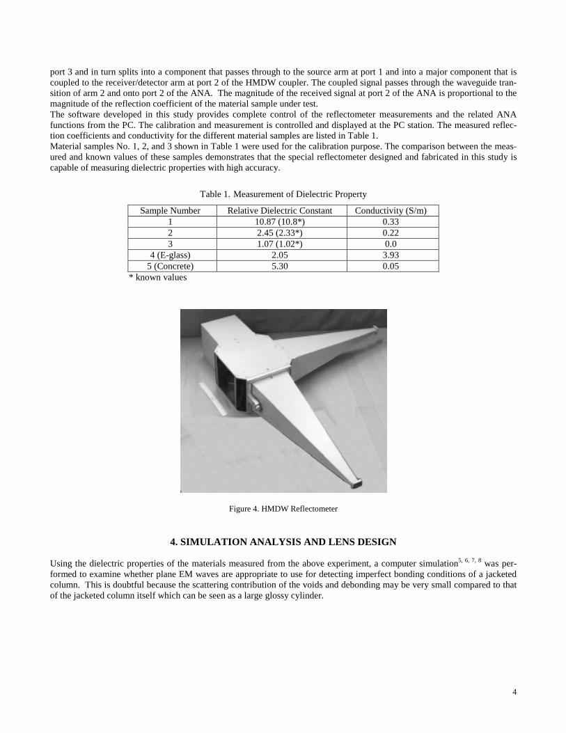
Figure 3. Experimental Setup for Dielectric Property Measurement The dielectric properties of each material are measured from the response of the material sample to plane wave excitation in free space. There are usually two fundamental difficulties associated with the measurement of the free space reflection and transmission with respect to the material sample: First, it is difficult to generate a uniform plane wave and second, unwanted parasitic reflections and multiple reflections are produced in the measurement path. Fortunately, with its special design, the reflectometer used in this study virtually eliminates both of these problems3, 4, however. The design of the reflectometer is based on the use of hollow metal dielectric waveguide (HMDW) as the EM wave transmis-sion line structure or medium. The HMDW consists of a large (compared to wavelength) rectangular waveguide with thin non-resonant dielectric and absorber layers on two opposite walls, or on all four walls. The useful operating mode of this transmission structure is the mode LM11. It is a linearly polarized longitudinal magnetic wave with a simple field structure (no nulls) over both transverse directions within the interior. In addition, special tapered waveguide transitions are used to transform the transmission mode from the standard waveguide TE10 mode (for X-band in the evaluation unit) to the LM11 mode of the reflectometer. The aperture of the reflectometer is of the order of 7 wavelengths by 7 wavelengths square (this is 200 mm by 200 mm for the X-band evaluation unit). The LM11 mode of the reflectometer has several unique properties. First, this mode has very low losses. Second, the longitudinal field components are small, that is, the field is nearly transverse electromagnetic, and hence it is almost a plane wave. Third, the longitudinal currents at the waveguide walls are vanishingly small. This results in very small diffraction at any transition from this waveguide to free space. These features figure promi-nently in the design and operation of the HMDW reflectometer. The small diffraction of the LM11 mode from the edges at the waveguide-to-space transition keeps the parasitic reflections from the aperture perimeter at the test plane very low. Having very low parasitic reflections from the aperture allows the instrument to be effectively used for the characterization of sam-ples with very small reflection coefficients such as the FRP composites which have dielectric constants in the range of 2 to 4. As shown in Figure 3, the reflectometer has four ports. A microwave signal from port 1 of the ANA is fed into the small end of the tapered transition connected to port 1 of the HMDW cross directional coupler, and is converted from the TE mode to LM mode. The signal passes through the HMDW cross waveguide coupler at port 1. Part of the signal goes to the load at port 4, while most of the signal passed through, to the sample under test at port 3. The reflection from the sample returns through
Port 1 Port 2
Port 3
Port 4
Port 1
Port 2
4
port 3 and in turn splits into a component that passes through to the source arm at port 1 and into a major component that is coupled to the receiver/detector arm at port 2 of the HMDW coupler. The coupled signal passes through the waveguide tran-sition of arm 2 and onto port 2 of the ANA. The magnitude of the received signal at port 2 of the ANA is proportional to the magnitude of the reflection coefficient of the material sample under test. The software developed in this study provides complete control of the reflectometer measurements and the related ANA functions from the PC. The calibration and measurement is controlled and displayed at the PC station. The measured reflec-tion coefficients and conductivity for the different material samples are listed in Table 1. Material samples No. 1, 2, and 3 shown in Table 1 were used for the calibration purpose. The comparison between the meas-ured and known values of these samples demonstrates that the special reflectometer designed and fabricated in this study is capable of measuring dielectric properties with high accuracy.
Table 1. Measurement of Dielectric Property
Sample Number Relative Dielectric Constant Conductivity (S/m) 1 10.87 (10.8*) 0.33 2 2.45 (2.33*) 0.22 3 1.07 (1.02*) 0.0
4 (E-glass) 2.05 3.93 5 (Concrete) 5.30 0.05
* known values
Figure 4. HMDW Reflectometer
4. SIMULATION ANALYSIS AND LENS DESIGN
Using the dielectric properties of the materials measured from the above experiment, a computer simulation5, 6, 7, 8 was per-formed to examine whether plane EM waves are appropriate to use for detecting imperfect bonding conditions of a jacketed column. This is doubtful because the scattering contribution of the voids and debonding may be very small compared to that of the jacketed column itself which can be seen as a large glossy cylinder.

5
Figure 5. Model of FPR-Jacketed Concrete Column with Maximum Void
In the computer simulation, the column is treated as a two dimensional scatterer, and the air gap is assumed to extend around the entire column, as shown in Figure 5. Although such a huge air void is unrealistic, the effect of the scattering due to the void is maximized under these conditions. Therefore, if this maximum void cannot be detected, any smaller and more realis-tic voids will unlikely be detectable. A computer program was developed for this jacketed column model using the measured dielectric constants and conductivity. Total electric field distributions obtained from the simulation using 20 GHz plane EM waves are shown in Figure 6, respec-tively for the jacketed columns with and without the air gap. As expected, the scattering due to the column itself hide the scattering due to the air gap (voids/debonding), and thus the difference between the columns with and without the air gap cannot be observed. Similar observations were made using 5 GHz plane waves. From this preliminary simulation analysis, it can be concluded that the plane EM is not capable of distinguishing the imperfect bonding condition from the perfect one.
Figure 6. Total Electric Field Distribution at 20GHz for the Two Cases: Without Air Gap (defect) and With Air Gap
In order to overcome this difficulty, the use of a dielectric lens is invoked to focus the electromagnetic wave on the interested region (bonding interface of the jacketed column in this case) while diffusing the field in other regions of no interest. Waves reflected from the other regions where the beam is defocused will have relatively small amplitude, and thus the differences between perfect bonding and imperfect one can be detected more effectively in this way. The concept of using a lens to fo-cus the wave is illustrated in Figure 7.
dist
ance
from
cen
ter
of th
e co
lum
n (m
)
distance from center of the column (m)
distance from center
of the column (m
)
distance from center of the column (m)

6
Figure 7. Use of Dielectric Lens to Focus Waves on Bonding Interface of Jacketed Column
Figure 8. Dielectric Lens Designed The dielectric lens designed in this study is shown in Figure 8. The lens was not optimized for reflection measurement (S11), so the optimal set-up will include two lenses as illustrated in Figure 9 to perform transmission measurement (S21). In other words, one lens is used to transmit waves and the other to receive the reflected waves. The angle of 40 degrees between the two lenses as shown in Figure 9 is the most ideal angle in terms of the wave receiving quality.
Figure 9. Set Up for the Reflection and Transmission Measurement
lens 1 lens 2
jacket

7
In order to remove spurious responses, the time gating technique is used. This technique allows one to select a specified time frame in which the received or reflected signal is to be observed (time gating). Use of time gating permits one to remove unwanted reflections due to unavoidable obstacles different from air voids, such as internal reflections and air to lens reflec-tion. The time gating concept is illustrated in Figure 10.
Figure 10. Time Gating of Reflection Signal
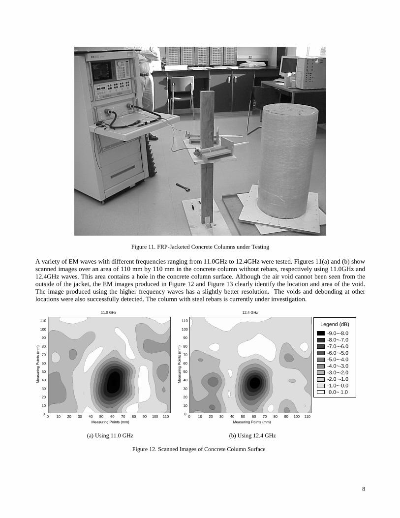
5. EXPERIMENTAL VERIFICATION ON FRP-JACKETED RC COLUMNS The effectiveness of the proposed EM imaging technology using focused EM waves and reflection analysis is investigated through experiments on FRP-jacketed RC columns. Three concrete columns of 16-in in diameter and 32-in in height were built. Two of these columns were built without reinforcing rebars and the third with No. 5 longitudinal rebars, in order to examine the influence of steel rebars on the detection. Each of the columns was wrapped with a three-layer glass FRP jacket. The thickness of each layer is 1.143 mm (0.045 in). Various voids and debonding conditions were artificially introduced between the jackets and the columns and between the layers of the jackets. Some voids were caused by the holes on the concrete column surface which remained there although supposed to be filled before the application of jackets. Others were introduced by inserting a small block of Styrofoam in the bonding interface, which has the same dielectric property as that of the air. Figure 11 is a photo showing one of the columns under testing. Two specially designed lenses are placed in 40 degrees with each other on a support that can slide up and down. One lens focuses the EM waves sent from the ANA on the column jacket, the other receives the waves reflected from the column. Two pieces of disks with smooth surfaces are installed on the bottom of each column, making it easily rotate. With the lenses sliding up and down and the column rotating, the entire surface of the jacketed column can be easily scanned. The analyzer receives the reflected wave signal from the lens and compares it with a reference value representing a perfect bonding situation. Both time- and frequency-domain analysis can be performed. A computer program was developed espe-cially for a PC to control the operation of the EM image scan.
8
Figure 11. FRP-Jacketed Concrete Columns under Testing
A variety of EM waves with different frequencies ranging from 11.0GHz to 12.4GHz were tested. Figures 11(a) and (b) show scanned images over an area of 110 mm by 110 mm in the concrete column without rebars, respectively using 11.0GHz and 12.4GHz waves. This area contains a hole in the concrete column surface. Although the air void cannot been seen from the outside of the jacket, the EM images produced in Figure 12 and Figure 13 clearly identify the location and area of the void. The image produced using the higher frequency waves has a slightly better resolution. The voids and debonding at other locations were also successfully detected. The column with steel rebars is currently under investigation.
11.0 GHz
Measuring Points (mm)
Mea
surin
g P
oint
s (m
m)
0 10 20 30 40 50 60 70 80 90 100 1100
10
20
30
40
50
60
70
80
90
100
110
12.4 GHz
Measuring Points (mm)
Mea
surin
g P
oint
s (m
m)
0 10 20 30 40 50 60 70 80 90 100 1100
10
20
30
40
50
60
70
80
90
100
110
(a) Using 11.0 GHz (b) Using 12.4 GHz
Figure 12. Scanned Images of Concrete Column Surface
-9.0~-8.0 -8.0~-7.0 -7.0~-6.0 -6.0~-5.0 -5.0~-4.0 -4.0~-3.0 -3.0~-2.0 -2.0~-1.0 -1.0~-0.0 0.0~ 1.0
Legend (dB)

9
(a) Using 11.0 GHz (b) Using 12.4 GHz
Figure 13. Scanned 3D Images of Concrete Column Surface
6. CONCLUSIONS An EM imaging technology has been developed in this study for detecting voids and debonding in the bonding interface of FRP-jacketed RC columns. The following conclusions can be drawn from simulation analysis and experiments:
(1) A plane EM wave is not capable of detecting voids and debonding. An especially designed dielectric lens is needed to focus the wave on the region of interest (bonding interface in this study).
(2) The special HMDW reflectometer used for measuring dielectric properties of the materials involved in an FRP-jacketed concrete column provides sufficiently accurate results.
(3) The voids and debonding in FRP jacketed columns are successfully detected by the proposed EM imaging technology.
ACKNOWLEDGEMENTS This work was supported by the National Science Foundation under Grants CMS-9812585 and CMS-9812856.
REFERENCES
1. Haroun, M. A. and Feng, M.Q. "Lap Splice and Shear Enhancements in Composite-Jacketed Bridge Columns", Proceed-
ings of the 3rd US-Japan Bridge Workshop, Tsububa, Japan, 1997. 2. Feng, M. Q., Liu, C., He, X., and Shinozuka, M. “Electromagnetic Image Reconstruction for Damage Detection”, Ac-
cepted for publication in Journal of Engineering Mechanics, ASCE, 2000. 3. F. D. Flaviis, M. Noro, R. E. Diaz, and N. G. Alexopoulos, "Diaz-Fitzgerald Time Domain (D-FTD) Technique Applied
to Electromagnetic Problem", IEEE MTT-S Int. Microwave Symp., S. Francisco, June, 1996 4. F. D. Flaviis, M. Noro, R. E. Diaz, and N. G. Alexopoulos, "Diaz-Fitzgerald Time Domain Method Applied to Electric
and Magnetic Debye Materials", Applied Computational Electromagnetics, ACES Symposium, Monterey(CA), March 17-21, 1997
5. F. D. Flaviis, M. Noro, R. E. Diaz, and N. G. Alexopoulos, "Time Domain Vector Potential Formulation for The Solu-tion of Electromagnetic Problems", IEEE AP-S Int. Symp., Montreal, Canada, July, 1997
6. F. D. Flaviis, M. Noro, R. E. Diaz, and N. G. Alexopoulos, "Diaz-Fitzgerald Time Domain Model for the Solution of Electromagnetic Problems", NATO-ANSI Conference, Samos, Greece, August 5, 1997
7. F. D. Flaviis, M. Noro, N. G. Alexopoulos, R. E. Diaz, and G. Franceschetti, "Extensions to Complex Materials of the Diaz-Fitzgerald Model for the Solution of Electromagnetic Problems", Electromagnetics, vol. 18, pp 35~65, 1998
8. F. D. Flaviis, M. Noro, R. E. Diaz, G. Franceschetti, and N. G. Alexopoulos, "A Vector Potential Formulation for the Solution of Electromagnetic Problems", IEEE Microwave Letters, pp 310~312, 1998