Embed Size (px)
Citation preview

EUROPEAN ORGANISATION FOR THE SAFETY OF AIR NAVIGATION
EUROCONTROL
EUROPEAN AIR TRAFFIC MANAGEMENT PROGRAMME
APPLICATION OF ASTERIX TO ARTAS
Document Ref. : DIS/SUR/ARTAS/ASTX.015 Edition : 7.00 Edition Date : 06/01/2009 Status : Draft
Page 2 INTERFACE SPECIFICATION EUROCONTROL
06/01/2009 APPLICATION OF ASTERIX TO ARTAS DAP/SUR
Version 7.00 (DIS/SUR/ARTAS/ASTX.015) ARTAS
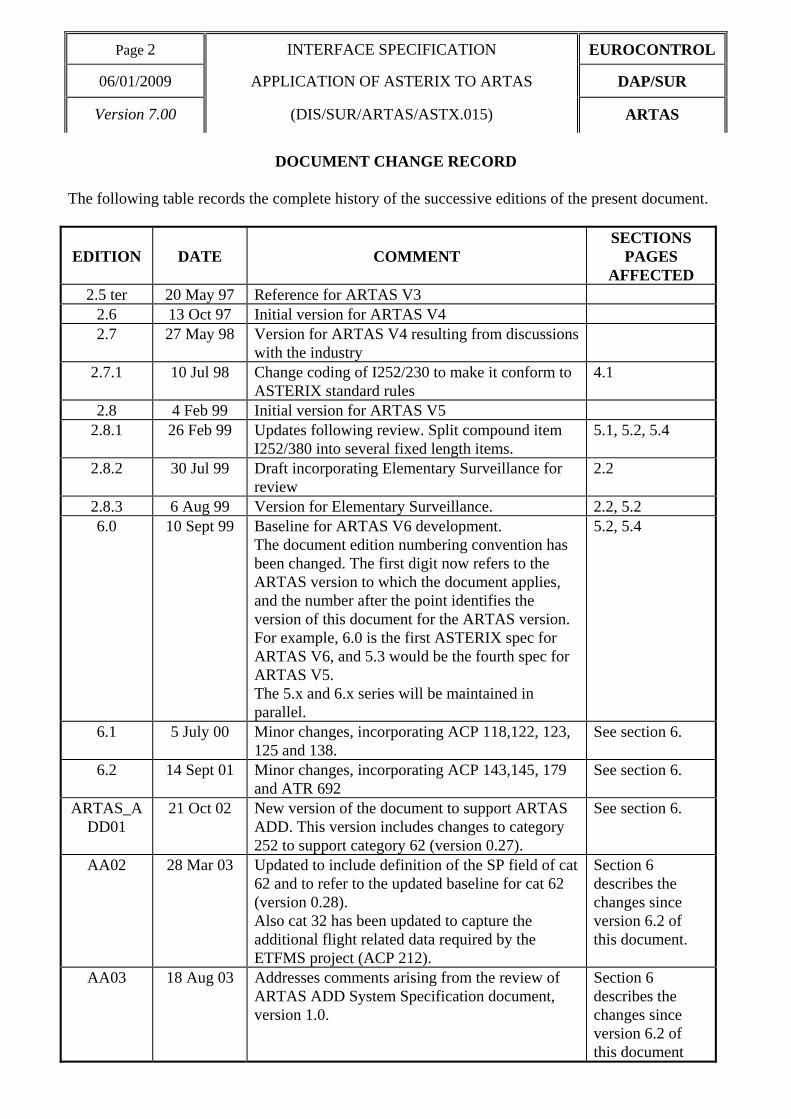
DOCUMENT CHANGE RECORD The following table records the complete history of the successive editions of the present document.
EDITION
DATE
COMMENT
SECTIONS PAGES
AFFECTED 2.5 ter 20 May 97 Reference for ARTAS V3
2.6 13 Oct 97 Initial version for ARTAS V4 2.7 27 May 98 Version for ARTAS V4 resulting from discussions
with the industry
2.7.1 10 Jul 98 Change coding of I252/230 to make it conform to ASTERIX standard rules
4.1
2.8 4 Feb 99 Initial version for ARTAS V5 2.8.1 26 Feb 99 Updates following review. Split compound item
I252/380 into several fixed length items. 5.1, 5.2, 5.4
2.8.2 30 Jul 99 Draft incorporating Elementary Surveillance for review
2.2
2.8.3 6 Aug 99 Version for Elementary Surveillance. 2.2, 5.2 6.0 10 Sept 99 Baseline for ARTAS V6 development.
The document edition numbering convention has been changed. The first digit now refers to the ARTAS version to which the document applies, and the number after the point identifies the version of this document for the ARTAS version. For example, 6.0 is the first ASTERIX spec for ARTAS V6, and 5.3 would be the fourth spec for ARTAS V5. The 5.x and 6.x series will be maintained in parallel.
5.2, 5.4
6.1 5 July 00 Minor changes, incorporating ACP 118,122, 123, 125 and 138.
See section 6.
6.2 14 Sept 01 Minor changes, incorporating ACP 143,145, 179 and ATR 692
See section 6.
ARTAS_ADD01
21 Oct 02 New version of the document to support ARTAS ADD. This version includes changes to category 252 to support category 62 (version 0.27).
See section 6.
AA02 28 Mar 03 Updated to include definition of the SP field of cat 62 and to refer to the updated baseline for cat 62 (version 0.28). Also cat 32 has been updated to capture the additional flight related data required by the ETFMS project (ACP 212).
Section 6 describes the changes since version 6.2 of this document.
AA03 18 Aug 03 Addresses comments arising from the review of ARTAS ADD System Specification document, version 1.0.
Section 6 describes the changes since version 6.2 of this document

EUROCONTROL INTERFACE SPECIFICATION Page 3
DAP/SUR APPLICATION OF ASTERIX TO ARTAS 06/01/2009
ARTAS (DIS/SUR/ARTAS.ASTX.015) Version 7.00
AA04 08 May 07 Remark in I030/060 updated. 2.2
7.0 06/01/2009 Finalisation of the document. The answers to the opened questions and remarks were provided. ACP 300: added wake turbulence category “super” to I030/435 and I032/435.
2.2, 4,2

Page 4 INTERFACE SPECIFICATION EUROCONTROL
06/01/2009 APPLICATION OF ASTERIX TO ARTAS DAP/SUR
Version 7.00 (DIS/SUR/ARTAS/ASTX.015) ARTAS
Table of content _________________
1 INTRODUCTION ______________________________________________________ 7
1.1 Scope of ASTERIX in ARTAS _____________________________________________________________7
1.2 Usage of ASTERIX by ARTAS Clients ______________________________________________________7
1.3 Conventions used in the document_________________________________________________________10
2 LAYOUT OF AIR SITUATION PICTURE MESSAGES ________________________ 11
2.1 List of Data Items of CATEGORY 030 _____________________________________________________12
2.2 Description of Data Items of CATEGORY 030 ______________________________________________15
2.3 User Application Profile for ARTAS Users__________________________________________________72
2.4 Encoding recommendations ______________________________________________________________75
2.5 Special Purpose Data Item of Category 62 __________________________________________________76
3 LAYOUT OF SENSOR INFORMATION MESSAGES _________________________ 79
3.1 List of Data Items of CATEGORY 031 _____________________________________________________80
3.2 Description of Data Items of CATEGORY 031 ______________________________________________81
3.3 User Application Profile for the transmission of Sensor information_____________________________92
3.4 Encoding recommendations ______________________________________________________________93
4 LAYOUT OF MESSAGES PROVIDED BY USERS TO ARTAS _________________ 94
4.1 List of Data Items of CATEGORY 032 _____________________________________________________95
4.2 Description of Data Items of CATEGORY 032 ______________________________________________96
4.3 User Application Profile for the transmission of Miniplans ___________________________________121
4.4 Encoding rules ________________________________________________________________________122
5 LAYOUT OF SESSION AND SERVICE CONTROL MESSAGES ______________ 123
5.1 List of Data Items of CATEGORY 252 ____________________________________________________125
5.2 Description of Data Items of CATEGORY 252 _____________________________________________128
5.3 Connection to ARTAS__________________________________________________________________193 5.3.1 UAP for connection related messages_____________________________________________________193 5.3.2 Encoding rules ______________________________________________________________________194

EUROCONTROL INTERFACE SPECIFICATION Page 5
DAP/SUR APPLICATION OF ASTERIX TO ARTAS 06/01/2009
ARTAS (DIS/SUR/ARTAS.ASTX.015) Version 7.00
5.4 Track and Sensor Information Service ____________________________________________________195
5.4.1 UAP for service related messages________________________________________________________195 5.4.2 Encoding rules ______________________________________________________________________198
6 SUMMARY OF MODIFICATIONS _______________________________________ 201

Page 6 INTERFACE SPECIFICATION EUROCONTROL
06/01/2009 APPLICATION OF ASTERIX TO ARTAS DAP/SUR
Version 7.00 (DIS/SUR/ARTAS/ASTX.015) ARTAS

EUROCONTROL INTERFACE SPECIFICATION Page 7
DAP/SUR APPLICATION OF ASTERIX TO ARTAS 06/01/2009
ARTAS (DIS/SUR/ARTAS.ASTX.015) Version 7.00
1 INTRODUCTION 1.1 Scope of ASTERIX in ARTAS
This document is applicable as from the version V7A1-PS3 of ARTAS. ARTAS uses the following ASTERIX categories to describe the format of the data it either sends or receives:
Category 1* : Mono-radar Data Target Reports
Category 2* : Mono-radar Service Messages
Category 21* : Transmission of ADS-B Messages
Category 23* : CNS/ATM Ground Station Service Messages
Category 30 : Exchange of Air Situation Pictures
Category 31 : Sensor Information
Category 32 : Miniplan
Category 34* : Mono-radar Service Messages
Category 48* : Mono-radar Target Reports
Category 62* : SDPS Track Messages
Category 63* : Sensor Status Messages
Category 65* : SDPS Service Status Messages
Category 252 : Session and Service Control Messages
Those categories marked with an asterisk are EUROCONTROL specifications under the control of the Radar Data Exchange Task Force (RDETF, previously RDEFG, formerly known as the STFRDE). Definitions of these categories can be obtained from the EUROCONTROL web site (http://www.eurocontrol.int/asterix/). The remaining categories listed above are defined for use specifically by ARTAS and are defined in this document. 1.2 Usage of ASTERIX by ARTAS Clients
As from the version V7A0 of ARTAS, new ASTERIX categories were introduced for the ARTAS clients: category 62, 63 and category 65.
Category 62 is a EUROCONTROL specification for system track data. It supports the various DAPs available from ADS-B and Mode-S Enhanced Surveillance, in addition to the existing track data and as such is a replacement for category 30.
Category 63 is a EUROCONTROL specification for sensor information. It is equivalent to category 31.
Category 65 is a EUROCONTROL specification for service status reporting. It includes the provision for reporting the status of a service (as done in cat 252 in ARTAS V6) and as such replaces category 252 for the reporting of service status in ARTAS.
In order to support existing clients ARTAS continues to support the existing category 30 and 31 definitions for broadcast services only, and continues to use category 252 (message types $3|1, $3|2,

Page 8 INTERFACE SPECIFICATION EUROCONTROL
06/01/2009 APPLICATION OF ASTERIX TO ARTAS DAP/SUR
Version 7.00 (DIS/SUR/ARTAS/ASTX.015) ARTAS
and $3|3) to report the service status for these broadcast services. Category 252 has been updated to support the dynamic definition of category 62 and 63 services, but will no longer support the definition of category 30 or 31 services (these services will have to be defined as broadcast services using the ARTAS operators terminal).
Table 1 below shows the combinations of ASTERIX categories supported by ARTAS.
To establish a connection and define a service
Track Service Sensor Service Service Status Reports
Point to Point User
CAT 252 CAT 62 CAT 63 CAT 65
Option a1 Not Applicable CAT 30 CAT 31 CAT 2522 Broadcast User
Option b Not Applicable CAT 62 CAT 63 CAT 65
Table 1 - Supported Combinations of ASTERIX Categories
1 Option a or option b can be chosen for a particular user, but it is not possible to choose one option for one service (e.g. option a for the track service) and another option for another service (e.g. option b for the sensor service). 2 The only service related reports used for the sensor service concern the definition, the interruption, the ending and the restart of a service.

EUROCONTROL INTERFACE SPECIFICATION Page 9
DAP/SUR APPLICATION OF ASTERIX TO ARTAS 06/01/2009
ARTAS (DIS/SUR/ARTAS.ASTX.015) Version 7.00
ARTAS Unit a
ARTAS Unit b
USER U3
USER U2 USER U1
CAT 252
CAT 62, 63, and 65
CAT 032
CAT 062, 63 and 65 CAT 062 and CAT 65
CAT 252
CAT 252
CAT 062 and CAT 032 All track related information that may be required in the context of both the tracking and service continuity are exchanged between
adjacent ARTAS Units.
User U1 is a pt-to-pt user, defining the required service using CAT 252, and receiving the track service in CAT 62, and a sensor service in cat 63 and track service status reports in CAT 65.
User U2 is an FPPS system. Connection and services are defined using CAT 252. The track information is sent in CAT 62, track service status reports are sent using CAT 65 and U2 sends ARTAS miniplans in CAT 32
User U3 is a broadcast user, receiving a track service in CAT 62 (and CAT 65 for track service status messages) and a sensor service using category 63.
USER U4
CAT 30. 252 and CAT 31
User U4 is a broadcast user, receiving track service in CAT 30 (and CAT 252 for track service status messages) andsensor service using category 31.
CAT 30: Air Situation Picture CAT 31: Sensor Information CAT 32: Miniplan Data CAT 62: System Track Data CAT 63: Sensor Information Messages CAT 65: Service Status CAT 252: Session and Service Control
Figure 1 : Typical data-flows in the ARTAS environment

Page 10 INTERFACE SPECIFICATION EUROCONTROL
06/01/2009 APPLICATION OF ASTERIX TO ARTAS DAP/SUR
Version 7.00 (DIS/SUR/ARTAS/ASTX.015) ARTAS
1.3 Conventions used in the document
ARTAS makes use of Extended length data fields and the associated Field Extension Indicator (FX) bit. In ARTAS the field extent is sent (and the associated FX bit set) when the extent contains necessary data i.e. a non-default value. Note: Throughout this document references to Mode C are used to represent both the Mode C information provided by secondary radars as well as Mode S altitude codes provided by Mode S stations, i.e. "Mode C" should be read as meaning "Mode C code or Mode S altitude code".

EUROCONTROL INTERFACE SPECIFICATION Page 11
DAP/SUR APPLICATION OF ASTERIX TO ARTAS 06/01/2009
ARTAS (DIS/SUR/ARTAS.ASTX.015) Version 7.00
2 LAYOUT OF AIR SITUATION PICTURE MESSAGES Previous versions of ARTAS have supported the exchange of track information to create an air situation picture through the use of category 30. Category 30 is an ARTAS specific category. The EUROCONTROL focus group for ASTERIX (the Radar Data Exchange Task Force RDETF) has recently defined a standard category for system track data, this is category 62. ARTAS supports both category 30 and category 62 for the provision of track data. Category 30 may be used for broadcast services only, whereas category 62 may be used for broadcast services or point-to-point services. ARTAS uses the Special Purpose (SP) data item of category 62 to encode a number of target report identifiers. These target report identifiers are created by using a hashing code algorithm on the received target report data. They are intended to assist in the system evaluation and future fault finding activities by providing a means to identify which plots/target reports have been used in each track update served by the system. A definition of the SP data item is provided in section 2.5.

Page 12 INTERFACE SPECIFICATION EUROCONTROL
06/01/2009 APPLICATION OF ASTERIX TO ARTAS DAP/SUR
Version 7.00 (DIS/SUR/ARTAS/ASTX.015) ARTAS
2.1 List of Data Items of CATEGORY 030 The data items which shall be used for the transmission of Air Situation Picture shall be that defined in Table 2 and described in the following pages.

EUROCONTROL INTERFACE SPECIFICATION Page 13
DAP/SUR APPLICATION OF ASTERIX TO ARTAS 06/01/2009
ARTAS (DIS/SUR/ARTAS.ASTX.015) Version 7.00
Table 2 - Data Items of Category 030
Data Item Reference Number
Description
System Units
I030/010 SERVER IDENTIFICATION TAG N.A. I030/015 USER NUMBER N.A. I030/020 TIME OF MESSAGE 1/128 s I030/030 SERVICE IDENTIFICATION N.A. I030/035 TYPE OF MESSAGE N.A. I030/040 TRACK NUMBER N.A. I030/050 ARTAS TRACK NUMBER N.A. I030/060 TRACK MODE 3/A N.A. I030/070 TIME OF LAST UPDATE 1/128 s I030/080 ARTAS TRACK STATUS N.A. I030/090 ARTAS TRACK QUALITY N.A. I030/100 CALCULATED TRACK POSITION (CARTESIAN) 1/32 or 1/64 NM I030/110 ESTIMATED ACCURACY OF TRACK POSITION (CARTESIAN) 1/32 or 1/64 NM I030/120 TRACK MODE 2 CODE N.A. I030/130 CALCULATED TRACK ALTITUDE 1/4 FL I030/135 ESTIMATED ACCURACY OF TRACK ALTITUDE 1/4 FL I030/140 LAST MEASURED MODE C 1/4 FL I030/150 MEASURED TRACK MODE C 1/4 FL I030/160 CALCULATED TRACK FLIGHT LEVEL 1/4 FL I030/165 ESTIMATED ACCURACY OF CALCULATED TRACK FLIGHT
LEVEL 1/4 FL
I030/170 TRACK AGES 1/4 s I030/180 CALCULATED TRACK VELOCITY (POLAR) 0.22 kt/0.0055 ° I030/181 CALCULATED TRACK VELOCITY (CARTESIAN) 0.22 kt I030/190 ESTIMATED ACCURACY OF TRACK VELOCITY (POLAR) 0.22 kt/0.0055 ° I030/191 ESTIMATED ACCURACY OF TRACK VELOCITY (CARTESIAN) 0.22 kt I030/200 MODE OF FLIGHT N.A. I030/210 MODE OF FLIGHT PROBABILITIES N.A. I030/220 CALCULATED RATE OF CLIMB/DESCENT 5.86 ft/min I030/230 ESTIMATED ACCURACY OF RATE OF CLIMB/DESCENT 5.86 ft/min I030/240 CALCULATED RATE OF TURN 1/4 °/s I030/250 ESTIMATED ACCURACY OF RATE OF TURN 1/4 °/s I030/260 RADAR IDENTIFICATION TAG N.A. I030/270 LOCAL TRACK NUMBER N.A. I030/290 PLOT AGES 1/4 s I030/340 LAST MEASURED MODE 3/A N.A. I030/360 MEASURED POSITION 1/128 NM/0.0055° I030/370 MEASURED 3-D HEIGHT 1/4 FL I030/382 AIRCRAFT ADDRESS N.A. I030/384 AIRCRAFT IDENTIFICATION N.A. I030/386 COMMUNICATIONS CAPABILITY AND FLIGHT STATUS N.A. I030/390 FPPS IDENTIFICATION TAG N.A. I030/400 CALLSIGN N.A. I030/410 PLN NUMBER N.A.

Page 14 INTERFACE SPECIFICATION EUROCONTROL
06/01/2009 APPLICATION OF ASTERIX TO ARTAS DAP/SUR
Version 7.00 (DIS/SUR/ARTAS/ASTX.015) ARTAS
Data Item Reference Number
Description
System Units
I030/420 FLIGHT CATEGORY N.A. I030/430 TYPE OF AIRCRAFT N.A. I030/435 CATEGORY OF TURBULENCE N.A. I030/440 DEPARTURE AIRPORT N.A. I030/450 DESTINATION AIRPORT N.A. I030/460 ALLOCATED SSR CODES N.A. I030/480 CURRENT CLEARED FLIGHT LEVEL 1/4 FL I030/490 CURRENT CONTROL POSITION N.A. I030/RE RESERVED EXPANSION DATA FIELD N.A.
N.A. = Not Applicable
EUROCONTROL INTERFACE SPECIFICATION Page 15
DAP/SUR APPLICATION OF ASTERIX TO ARTAS 06/01/2009
ARTAS (DIS/SUR/ARTAS.ASTX.015) Version 7.00
2.2 Description of Data Items of CATEGORY 030

Page 16 INTERFACE SPECIFICATION EUROCONTROL
06/01/2009 APPLICATION OF ASTERIX TO ARTAS DAP/SUR
Version 7.00 (DIS/SUR/ARTAS/ASTX.015) ARTAS
I030/010 : SERVER IDENTIFICATION TAG Definition : Identification of the Server of track information. Format : Two-byte fixed length data item. Structure :
Byte 1 Byte 2 16 15 14 13 12 11 10 9 8 7 6 5 4 3 2 1
SAC SIC bits 16/9 (SAC) Source Area Code (0 → 255) bits 8/1 (SIC) Source Identity Code (0 → 255) Remark(s) : SACs have been defined worldwide and can be accessed on the EUROCONTROL
ASTERIX website (www.eurocontrol.int/asterix).

EUROCONTROL INTERFACE SPECIFICATION Page 17
DAP/SUR APPLICATION OF ASTERIX TO ARTAS 06/01/2009
ARTAS (DIS/SUR/ARTAS.ASTX.015) Version 7.00
I030/015 : USER NUMBER Definition : Identification of the User of track information Format : Two-byte fixed length data item. Structure :
Byte 1 Byte 2 16 15 14 13 12 11 10 9 8 7 6 5 4 3 2 1
USER NUMBER bits 16/1 (USER NUMBER) User number (0 → 16#FFFF#) Remark(s) : The User numbers are predefined in the User registration data base of the ARTAS Unit to which the User wants to connect.

Page 18 INTERFACE SPECIFICATION EUROCONTROL
06/01/2009 APPLICATION OF ASTERIX TO ARTAS DAP/SUR
Version 7.00 (DIS/SUR/ARTAS/ASTX.015) ARTAS
I030/020 : TIME OF MESSAGE Definition : Absolute time stamping of the message in the form of elapsed time since last midnight Format : Three-byte fixed length data item. Structure :
Byte 1 24 23 22 21 20 19 18 17
Byte 2 Byte 3 16 15 14 13 12 11 10 9 8 7 6 5 4 3 2 1
LSB bit 1 (LSB) (2E-7) s = 1/128 s Remark(s) : This is the time at which a message is filled and not the time at which the data-block
containing the tracks is sent. The time of the day value is reset to 0 at every midnight.

EUROCONTROL INTERFACE SPECIFICATION Page 19
DAP/SUR APPLICATION OF ASTERIX TO ARTAS 06/01/2009
ARTAS (DIS/SUR/ARTAS.ASTX.015) Version 7.00
I030/030 : SERVICE IDENTIFICATION Definition : Identification of the service(s) to which a track message belongs. Format : Variable length data item comprising a first part of one byte followed by a 1-byte
extent as necessary. Structure :
Byte 1 16 15 14 13 12 11 10 9
sb BS C1 FX
Byte 2 8 7 6 5 4 3 2 1
C2 C3 C4 C5 sb bits 16/12 (sb) = spare bits set to 0 BS, C1, C2, C3, C4 and C5 are used to indicate which user service(s) has (have) originated the track message : bit 11 (BS) = 1 Track selected by the Background service bit 10 (C1) = 1 Track selected by the Complementary service 1 bit 9 (FX) Field extension bit 8 (C2) = 1 Track selected by the Complementary service 2 bit 7 (C3) = 1 Track selected by the Complementary service 3 bit 6 (C4) = 1 Track selected by the Complementary service 4 bit 5 (C5) = 1 Track selected by the Complementary service 5 bits 4/1 (sb) = spare bits set to 0 Remark(s) :

Page 20 INTERFACE SPECIFICATION EUROCONTROL
06/01/2009 APPLICATION OF ASTERIX TO ARTAS DAP/SUR
Version 7.00 (DIS/SUR/ARTAS/ASTX.015) ARTAS
I030/035 : TYPE OF MESSAGE Definition : This data item allows for a more convenient handling of the message at the receiver
side by further defining the type of transaction. Format : One-byte fixed length data item. Structure :
Byte 1 8 7 6 5 4 3 2 1
FAMILY NATURE bits 8/5 (FAMILY) to which the message belongs (0 to 15), bits 4/1 : (NATURE) of the message (within its FAMILY). (FAMILY) = 0 ARTAS coordination messages (NATURE) = 0000 track information message 0001 slave track promotion message Remark(s) : the Slave Track Promotion Messages are related to the inter-ARTAS cooperation and
cannot be served to the normal track information Users.
EUROCONTROL INTERFACE SPECIFICATION Page 21
DAP/SUR APPLICATION OF ASTERIX TO ARTAS 06/01/2009
ARTAS (DIS/SUR/ARTAS.ASTX.015) Version 7.00
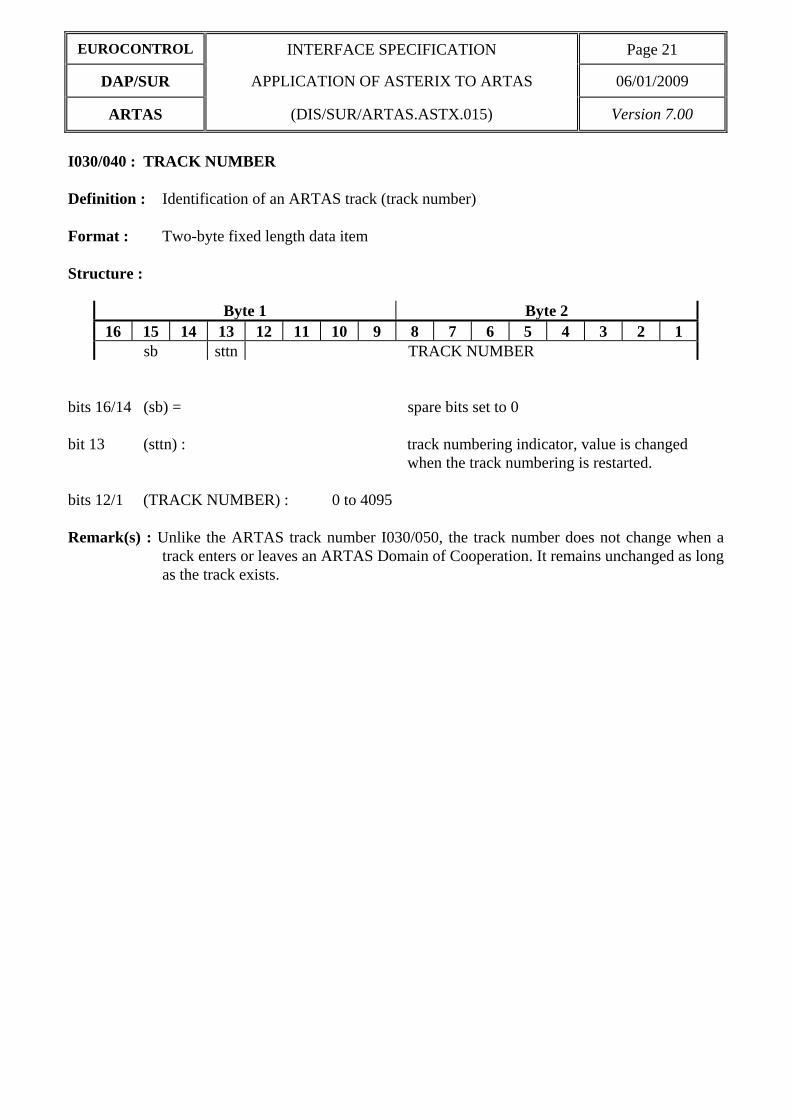
I030/040 : TRACK NUMBER Definition : Identification of an ARTAS track (track number) Format : Two-byte fixed length data item Structure :
Byte 1 Byte 2 16 15 14 13 12 11 10 9 8 7 6 5 4 3 2 1
sb sttn TRACK NUMBER bits 16/14 (sb) = spare bits set to 0 bit 13 (sttn) : track numbering indicator, value is changed
when the track numbering is restarted. bits 12/1 (TRACK NUMBER) : 0 to 4095 Remark(s) : Unlike the ARTAS track number I030/050, the track number does not change when a
track enters or leaves an ARTAS Domain of Cooperation. It remains unchanged as long as the track exists.

Page 22 INTERFACE SPECIFICATION EUROCONTROL
06/01/2009 APPLICATION OF ASTERIX TO ARTAS DAP/SUR
Version 7.00 (DIS/SUR/ARTAS/ASTX.015) ARTAS
I030/050 : ARTAS TRACK NUMBER Definition : Identification of an ARTAS track Format : Variable length data item comprising a first part of three bytes (Master Track Number),
followed by up to 5 extents of three bytes (Slave Track Numbers). Structure :
Byte 1 24 23 22 21 20 19 18 17
ARTAS UNIT IDENTIFICATION
Byte 2 Byte 3 16 15 14 13 12 11 10 9 8 7 6 5 4 3 2 1
SYSTEM TRACK NUMBER FX Each Local Track Number (i.e. either a Master or a Slave Track Number) is composed of the identification of the ARTAS UNIT processing the track together with the relevant SYSTEM TRACK NUMBER (i.e. the number of the track local to the ARTAS Unit in question). Each Local Track Number is unique. bits 24/17 (ARTAS UNIT IDENTIFICATION) : 0 to 255 bits 13/2 (SYSTEM TRACK NUMBER) : 0 to 4095 bit 1 (FX) = 0 end of data item 1 extension into next extent The MASTER TRACK NUMBER and the 5 possible extents (SLAVE TRACK NUMBER) are identically composed. The longer ARTAS Track Numbers (identifying tracks simultaneously processed in 6 adjacent Units numbered a to f) will have the following form :
UNIT a IDENT SYSTEM TRACK NUMBER IN UNIT a 1 UNIT b IDENT SYSTEM TRACK NUMBER IN UNIT b 1 UNIT c IDENT SYSTEM TRACK NUMBER IN UNIT c 1 UNIT d IDENT SYSTEM TRACK NUMBER IN UNIT d 1 UNIT e IDENT SYSTEM TRACK NUMBER IN UNIT e 1 UNIT f IDENT SYSTEM TRACK NUMBER IN UNIT f 0
Remark(s) : The ARTAS UNIT IDENTIFICATION NUMBERS will be given as soon as the
systems will be implemented.

EUROCONTROL INTERFACE SPECIFICATION Page 23
DAP/SUR APPLICATION OF ASTERIX TO ARTAS 06/01/2009
ARTAS (DIS/SUR/ARTAS.ASTX.015) Version 7.00
I030/060 : TRACK MODE 3/A Definition : Mode 3/A identity associated to the track Format : Two-byte fixed length data item. Structure :
Byte 1 Byte 2 16 15 14 13 12 11 10 9 8 7 6 5 4 3 2 1 V G C sb OCT1 OCT2 OCT3 OCT4
bit 16 (V) 0 Code validated 1 Code non validated bit 15 (G) 0 Default 1 Garbled code bit 14 (C) 0 No change of track Mode 3/A 1 Track Mode 3/A has changed bit 13 (sb) spare bit set to 0 bits 12/1 Mode 3/A Code under the form of 4 digits in octal representation : bits 12/10 : OCT1 = 1st octal digit, bits 9/7 : OCT2 = 2nd octal digit, bits 6/4 : OCT3 = 3rd octal digit, bits 3/1 : OCT4 = 4th octal digit, Remark(s) : A change of track Mode 3/A (C = 1) is indicated during 30 seconds after the code has
changed.
(V) and (G) are computed from the last Mode 3/A that was used to update the track.

Page 24 INTERFACE SPECIFICATION EUROCONTROL
06/01/2009 APPLICATION OF ASTERIX TO ARTAS DAP/SUR
Version 7.00 (DIS/SUR/ARTAS/ASTX.015) ARTAS
I030/070 : TIME OF LAST UPDATE Definition : Absolute time stamping of the information provided in the track message, in the form
of elapsed time since last midnight. Format : Three-byte fixed length data item. Structure :
Byte 1 24 23 22 21 20 19 18 17
Byte 2 Byte 3 16 15 14 13 12 11 10 9 8 7 6 5 4 3 2 1
LSB bit 1 (LSB) = 2-7 s = 1/128 s Remark(s) : In ARTAS, this is the time at which the track is extrapolated by the Server in case of
periodical service. Otherwise, this is the update time of the track state vector by the Tracker.
The time of the day value is reset to 0 at every midnight.

EUROCONTROL INTERFACE SPECIFICATION Page 25
DAP/SUR APPLICATION OF ASTERIX TO ARTAS 06/01/2009
ARTAS (DIS/SUR/ARTAS.ASTX.015) Version 7.00
I030/080 : ARTAS TRACK STATUS Definition : Status of an ARTAS track. Format: Variable length data item comprising a first part of one byte, followed by 1-byte
extents as necessary. Structure:
Byte 1 8 7 6 5 4 3 2 1
LIV CNF ADD CST TYPE FX bit 8 (LIV) = 1 Simulated or test target track 0 Live target bit 7 (CNF) = 1 Tentative track 0 Confirmed track bit 6 (ADD) = 1 track updated using Aircraft Derived Data 0 track not updated using Aircraft Derived Data bit 5 (CST) = 1 coasted track 0 non-coasted track bits 4/2 (TYPE)= 000 both PR and SSR Multiradar track 001 PR only Multiradar track 010 SSR only Multiradar track 011 not used 100 combined (P+S) monoradar track 101 PR monoradar track 110 SSR monoradar track 111 not used bit 1 (FX) = 0 end of data item 1 extension into first extent
[CONT'D]

Page 26 INTERFACE SPECIFICATION EUROCONTROL
06/01/2009 APPLICATION OF ASTERIX TO ARTAS DAP/SUR
Version 7.00 (DIS/SUR/ARTAS/ASTX.015) ARTAS
structure of first extent :
Byte 2 8 7 6 5 4 3 2 1
TRM CRE SLR COR FX bit 8 (TRM) = 0 default value 1 track TERMINATED (i.e. last message transmitted for the
track in question which is not continued anymore by the tracker).
bit 7 (CRE) = 0 default value 1 track CREATED (i.e. first message transmitted to the User
for the track in question) bit 6/5 (SLR) = 0 slant range corrected track coordinates using tracked MODE
C information. 1 slant range corrected track coordinates using triangulated
track height or height derived from coverage 2 slant range correction using assumed height 3 non slant range corrected track coordinates bits 4/2 (COR) = 000 confirmed flight plan to track correlation 001 type 1 correlation 010 type 2 correlation 011 type 3 correlation application 100 type 4 correlation dependent 101 type 5 correlation 110 type 6 correlation 111 track not correlated to a flight plan bit 1 (FX) = 0 End of data item 1 Extension into second extent
[CONT'D]

EUROCONTROL INTERFACE SPECIFICATION Page 27
DAP/SUR APPLICATION OF ASTERIX TO ARTAS 06/01/2009
ARTAS (DIS/SUR/ARTAS.ASTX.015) Version 7.00
structure of second extent :
Byte 3 8 7 6 5 4 3 2 1 sb sb FOR AMA SPI ME TDC FX
bit 8/7 (sb) Spare bits set to 0 bit 6 (FOR) = 0 Default 1 Formation flight : more than one aircraft may correspond to
the track. bit 5 (AMA) = 0 amalgamated track 1 non amalgamated track bit 4 (SPI) = 0 default value 1 Special Position Indication in the last SSR plot that was used
to update the track bit 3 (ME) = 0 default 1 Military Emergency bit 2 (TDC) 0 Accurate estimation of the track Transponder Delay enabling
correction of the plots associated to the track. 1 Estimation of the track Transponder Delay not accurate
enough to enable the plots correction. bit 1 (FX) = 0 End of data item 1 Extension into third extent
[CONT'D]

Page 28 INTERFACE SPECIFICATION EUROCONTROL
06/01/2009 APPLICATION OF ASTERIX TO ARTAS DAP/SUR
Version 7.00 (DIS/SUR/ARTAS/ASTX.015) ARTAS
structure of third extent :
Byte 4 8 7 6 5 4 3 2 1
SF sb FX
bit 8 (SF) = 0 Track position coding precision (1/64 NM), 1 Track position coding precision = 1/32 NM, bits 7/2 (sb) = spare bits set to 0 bit 1 (FX) = 0 End of data item 1 Extension into fourth extent Remark(s): 1. SLR (slant range correction, bits 6/5 of first extent) will not be set to 3 in ARTAS. 2. In ARTAS, COR is set to 001 (type 1 correlation) when either no flight plan is available from the
preferred FPPS User or no preferred FPPS User has been specified but the track is correlated to flight plan(s) from other FPPS Users which do not provide a unique control position (i.e. either none of them provides a control position or they provide different values).
3. If the track coding precision is 1/64, the third extent will not be sent.

EUROCONTROL INTERFACE SPECIFICATION Page 29
DAP/SUR APPLICATION OF ASTERIX TO ARTAS 06/01/2009
ARTAS (DIS/SUR/ARTAS.ASTX.015) Version 7.00
I030/090 : ARTAS TRACK QUALITY Definition : ARTAS track quality. Format : One byte fixed length data item. Structure :
Byte 1 8 7 6 5 4 3 2 1
sb Quality bits 8/4 (sb) spare bits set to 0 bits 3/1 (Quality) ARTAS track quality = 0 (low quality) to 7 (high quality) Remark(s) :

Page 30 INTERFACE SPECIFICATION EUROCONTROL
06/01/2009 APPLICATION OF ASTERIX TO ARTAS DAP/SUR
Version 7.00 (DIS/SUR/ARTAS/ASTX.015) ARTAS
I030/100 : CALCULATED TRACK POSITION (CARTESIAN) Definition : Calculated position of an aircraft expressed in Cartesian coordinates. Format : Four-byte fixed length data item. Structure :
Byte 1 Byte 2 32 31 30 29 28 27 26 25 24 23 22 21 20 19 18 17
X-Component LSB
Byte 3 Byte 4 16 15 14 13 12 11 10 9 8 7 6 5 4 3 2 1
Y-Component LSB
bits 17 and 1 (LSB) = 2-6+f where f is the scaling factor applied, modifying
the standard precision. Maximum value = (29+f - LSB) NM Remark(s) : Basically, f=0, i.e. LSB = 1/64 NM and range = - 512 NM .. 511.984 NM
A scaling factor of f=1 is required for any User defining a Domain of Interest extending beyond a square of approximately 1024 NM X 1024 NM centred on the Unit Centre Point (i.e. the origin of the stereographic projection) of the ARTAS Unit to which it is connected. In this case, LSB will be 1/32 NM and the maximum coding range will be approximately 2048 NM (- 1024 NM .. 1023.968 NM ). The scaling factor is defined in item I252/340.

EUROCONTROL INTERFACE SPECIFICATION Page 31
DAP/SUR APPLICATION OF ASTERIX TO ARTAS 06/01/2009
ARTAS (DIS/SUR/ARTAS.ASTX.015) Version 7.00
I030/110 : ESTIMATED ACCURACY OF TRACK POSITION (CARTESIAN) Definition : Estimated accuracy (i.e. standard deviation) of the calculated position of an aircraft
expressed in Cartesian coordinates. Format : Four-byte fixed length data item. Structure :
Byte 1 Byte 2 32 31 30 29 28 27 26 25 24 23 22 21 20 19 18 17
X-Component accuracy LSB
Byte 3 Byte 4 16 15 14 13 12 11 10 9 8 7 6 5 4 3 2 1
Y-Component accuracy LSB
bits 17 and 1 (LSB) = 2-6+f where f is the scaling factor applied, modifying the
standard precision. Maximum value = (29+f - LSB) NM Remark(s) : Accuracy concerns both X and Y coordinate components.

Page 32 INTERFACE SPECIFICATION EUROCONTROL
06/01/2009 APPLICATION OF ASTERIX TO ARTAS DAP/SUR
Version 7.00 (DIS/SUR/ARTAS/ASTX.015) ARTAS
I030/120 : TRACK MODE 2 CODE Definition : Mode 2 identification associated to the track Format : Two-byte fixed length data item. Structure :
Byte 1 Byte 2 16 15 14 13 12 11 10 9 8 7 6 5 4 3 2 1 V G C sb OCT1 OCT2 OCT3 OCT4
bit 16 (V) = 0 Code validated 1 Code non validated bit 15 (G) = 0 Default 1 Garbled code bit 14 (C) = 0 No change of track Mode 2 1 Track Mode 2 has changed bit 13 (sb) = spare bit set to 0 bits 12/1 Mode 2 reply under the form of 4 digits in octal representation : bits 12/10 : OCT1 = 1st octal digit, bits 9/7 : OCT2 = 2nd octal digit, bits 6/4 : OCT3 = 3rd octal digit, bits 3/1 : OCT4 = 4th octal digit, Remark(s) : a change of track Mode 2 (C = 1) is indicated during 30 seconds after the code has
changed. (V) and (G) are extracted from the last Mode 2 that was used to update the track.

EUROCONTROL INTERFACE SPECIFICATION Page 33
DAP/SUR APPLICATION OF ASTERIX TO ARTAS 06/01/2009
ARTAS (DIS/SUR/ARTAS.ASTX.015) Version 7.00
I030/130 : CALCULATED TRACK ALTITUDE Definition : Calculated altitude of an aircraft. Format : Two-byte fixed length data item. Structure :
Byte 1 Byte 2 16 15 14 13 12 11 10 9 8 7 6 5 4 3 2 1
SRC ALTITUDE LSB
bit 16/15 (SRC) = 0 3D height 1 Triangulated height 2 Height derived from coverage 3 Assumed height bit 14/1 calculated track altitude (LSB) = 25 feet Vmin = -1500 ft Vmax = 150000 ft Remark(s) : SRC indicates the source used to compute the altitude.

Page 34 INTERFACE SPECIFICATION EUROCONTROL
06/01/2009 APPLICATION OF ASTERIX TO ARTAS DAP/SUR
Version 7.00 (DIS/SUR/ARTAS/ASTX.015) ARTAS
I030/135 : ESTIMATED ACCURACY OF TRACK ALTITUDE Definition : Estimated accuracy (i.e. standard deviation) of the calculated altitude of an aircraft. Format : Two-byte fixed length data item. Structure :
Byte 1 Byte 2 16 15 14 13 12 11 10 9 8 7 6 5 4 3 2 1
ALTITUDE ACCURACY LSB
(LSB) = 25 ft Remark(s) :

EUROCONTROL INTERFACE SPECIFICATION Page 35
DAP/SUR APPLICATION OF ASTERIX TO ARTAS 06/01/2009
ARTAS (DIS/SUR/ARTAS.ASTX.015) Version 7.00
I030/140 : LAST MEASURED MODE C Definition : Mode C code of the last nearest neighbour plot containing a Mode C and used to
update the track. Format : Two-byte fixed length data item. Structure :
Byte 1 Byte 2 16 15 14 13 12 11 10 9 8 7 6 5 4 3 2 1
VAL GC MODE C LSB bit 16 (VAL) = Validity indicator of the Flight Level 0 valid Mode C code 1 invalid Mode C code bit 15 (GC) = 0 default value 1 garbled information bit 14/1 (MODE C) (LSB) = 1/4 FL = 25 feet Vmin = -12 FL = -1200 ft Vmax = 1270 FL = 127000 ft Remark(s) : 1: The VAL and GC indications are derived from the local track/plot message.

Page 36 INTERFACE SPECIFICATION EUROCONTROL
06/01/2009 APPLICATION OF ASTERIX TO ARTAS DAP/SUR
Version 7.00 (DIS/SUR/ARTAS/ASTX.015) ARTAS
I030/150 : MEASURED TRACK MODE C Definition : Last validated and credible Mode C value used to update the track. Format : Two-byte fixed length data item. Structure :
Byte 1 Byte 2 16 15 14 13 12 11 10 9 8 7 6 5 4 3 2 1
sb MODE C LSB bits 16/15 (sb)= Spare bits set to 0 bits 16/1 (MODE C) (LSB) = 1/4 FL = 25 feet Vmin = -12 FL = -1200 ft Vmax = 1270 FL = 127000 ft Remark(s) : There are tracker parameters that determine whether the validity and garbled indicators
are considered in the determination of the last validated and credible Mode C.

EUROCONTROL INTERFACE SPECIFICATION Page 37
DAP/SUR APPLICATION OF ASTERIX TO ARTAS 06/01/2009
ARTAS (DIS/SUR/ARTAS.ASTX.015) Version 7.00
I030/160 : CALCULATED TRACK FLIGHT LEVEL Definition : Calculated Flight Level of the track (isobar). Format : Two-byte fixed length data item. Structure :
Byte 1 Byte 2 16 15 14 13 12 11 10 9 8 7 6 5 4 3 2 1 sb QNC CALCULATED TRACK FLIGHT LEVEL LSB
bit 16 (sb) = spare bit set to 0 bit 15 (QNC) = 0 FL calculated without QNH correction 1 FL calculated with QNH correction bit 14/1 (TRACK FLIGHT LEVEL) (LSB) = 1/4 FL = 25 feet Vmin = -15 FL = -1500 ft Vmax = 1500 FL = 150000 ft Remark(s) : the QNH is not processed in ARTAS : bit QNC is always 0.

Page 38 INTERFACE SPECIFICATION EUROCONTROL
06/01/2009 APPLICATION OF ASTERIX TO ARTAS DAP/SUR
Version 7.00 (DIS/SUR/ARTAS/ASTX.015) ARTAS
I030/165 : ESTIMATED ACCURACY OF CALCULATED TRACK FLIGHT LEVEL Definition : Estimated accuracy (i.e. standard deviation) of the calculated Flight Level of the track
(isobar). Format : Two-byte fixed length data item. Structure :
Byte 1 Byte 2 16 15 14 13 12 11 10 9 8 7 6 5 4 3 2 1
CALCULATED TRACK FLIGHT LEVEL ACCURACY LSB
bit 1 (LSB) = 1/4 FL = 25 feet Remark(s) :

EUROCONTROL INTERFACE SPECIFICATION Page 39
DAP/SUR APPLICATION OF ASTERIX TO ARTAS 06/01/2009
ARTAS (DIS/SUR/ARTAS.ASTX.015) Version 7.00
I030/170 : TRACK AGES Definition : A set of track related ages. Format : Four-byte fixed length data item. Structure :
Byte 1 Byte 2 32 31 30 29 28 27 26 25 24 23 22 21 20 19 18 17
PSR LSB SSR LSB
Byte 3 Byte 4 16 15 14 13 12 11 10 9 8 7 6 5 4 3 2 1
AMODE LSB CMODE LSB
bits 32/25 (PSR) Age of the last primary plot/local track used to update the track bit 25 (LSB) = 1/4 s maximum value = 63.75 s bits 24/17 (SSR) Age of the last secondary plot/local track used to update the track bit 17 (LSB) = 1/4 s maximum value = 63.75 s bits 16/9 (AMODE) Age of the last detection of the mode A contained in the track mode A item
I030/060. bit 9 (LSB) = 1/4 s maximum value = 63.75 s bits 8/1 (CMODE) Age of the last valid and credible mode C used to update the track, contained
in I030/150. bit 1 (LSB) = 1/4 s maximum value = 63.75 s Remark(s) : The ages are counted from I030/070 TIME OF LAST UPDATE, using the following
formula : age = I030/070 - time.

Page 40 INTERFACE SPECIFICATION EUROCONTROL
06/01/2009 APPLICATION OF ASTERIX TO ARTAS DAP/SUR
Version 7.00 (DIS/SUR/ARTAS/ASTX.015) ARTAS
If the computed age is greater than the maximum value or if the associated information has never been received, then the maximum value is returned.
If the computed age is negative, then 0 is returned. The track mode A is contained in I030/060 TRACK MODE 3/A. The last valid and credible mode C is contained in I030/150 MEASURED TRACK
MODE C.

EUROCONTROL INTERFACE SPECIFICATION Page 41
DAP/SUR APPLICATION OF ASTERIX TO ARTAS 06/01/2009
ARTAS (DIS/SUR/ARTAS.ASTX.015) Version 7.00
I030/180 : CALCULATED TRACK VELOCITY (POLAR) Definition : Calculated track velocity expressed in polar coordinates. Format : Four-byte fixed length data item. Structure :
Byte 1 Byte 2 32 31 30 29 28 27 26 25 24 23 22 21 20 19 18 17
SPEED LSB
Byte 3 Byte 4 16 15 14 13 12 11 10 9 8 7 6 5 4 3 2 1
HEADING LSB
(SPEED) : bit 17 (LSB) = 2-14 NM/s ≅ 0.22 kt Maximum value = 2 NM/s = 7200 kt (HEADING) : bit 1 (LSB) = 360° / 216 = 0.0055° Remark(s) :

Page 42 INTERFACE SPECIFICATION EUROCONTROL
06/01/2009 APPLICATION OF ASTERIX TO ARTAS DAP/SUR
Version 7.00 (DIS/SUR/ARTAS/ASTX.015) ARTAS
I030/181 : CALCULATED TRACK VELOCITY (CARTESIAN) Definition : Calculated track velocity expressed in Cartesian coordinates. Format : Four-byte fixed length data item. Structure :
Byte 1 Byte 2 32 31 30 29 28 27 26 25 24 23 22 21 20 19 18 17
X-VELOCITY COMPONENT LSB
Byte 3 Byte 4 16 15 14 13 12 11 10 9 8 7 6 5 4 3 2 1
Y-VELOCITY COMPONENT LSB
(X/Y-VELOCITY COMPONENTS) : bits 17 and 1 (LSB) 2-14 NM/s ≅ 0.22 kt Maximum value = 2 NM/s = 7200 kt Remark(s) :

EUROCONTROL INTERFACE SPECIFICATION Page 43
DAP/SUR APPLICATION OF ASTERIX TO ARTAS 06/01/2009
ARTAS (DIS/SUR/ARTAS.ASTX.015) Version 7.00
I030/190 : ESTIMATED ACCURACY OF TRACK VELOCITY (POLAR) Definition : Estimated accuracy (i.e. standard deviation) of the calculated track velocity expressed
in polar coordinates. Format : Four-byte fixed length data item. Structure :
Byte 1 Byte 2 32 31 30 29 28 27 26 25 24 23 22 21 20 19 18 17
SPEED COMPONENT ACCURACY LSB
Byte 3 Byte 4 16 15 14 13 12 11 10 9 8 7 6 5 4 3 2 1
HEADING COMPONENT ACCURACY LSB
(SPEED COMPONENT ACCURACY) : bit 17 (LSB) = 2-14 NM/s ≅ 0.22 kt (HEADING COMPONENT ACCURACY) : bit 1 (LSB) = 360° / 216 ≅ 0.0055° Remark(s) :

Page 44 INTERFACE SPECIFICATION EUROCONTROL
06/01/2009 APPLICATION OF ASTERIX TO ARTAS DAP/SUR
Version 7.00 (DIS/SUR/ARTAS/ASTX.015) ARTAS
I030/191 : ESTIMATED ACCURACY OF TRACK VELOCITY (CARTESIAN) Definition : Estimated accuracy (i.e. standard deviation) of the calculated track velocity expressed
in Cartesian coordinates. Format : Four-byte fixed length data item. Structure :
Byte 1 Byte 2 32 31 30 29 28 27 26 25 24 23 22 21 20 19 18 17
X-velocity component accuracy LSB
Byte 3 Byte 4 16 15 14 13 12 11 10 9 8 7 6 5 4 3 2 1
Y-velocity component accuracy LSB
(VX and VY VELOCITY COMPONENTS ACCURACY) : bits 32 and 16 Sign bit set to 0 (accuracy is an absolute value). bits 16 and 1 (LSB) = 2-14 NM/s ≅ 0.22 kt Remark(s) :

EUROCONTROL INTERFACE SPECIFICATION Page 45
DAP/SUR APPLICATION OF ASTERIX TO ARTAS 06/01/2009
ARTAS (DIS/SUR/ARTAS.ASTX.015) Version 7.00
I030/200 : MODE OF FLIGHT Definition : Calculated Mode-of-Flight of an aircraft. Format : One-byte fixed length data item. Structure :
Byte 1 8 7 6 5 4 3 2 1 TRANS LONGI VERTI sb
bits 8/7 (TRANS) : Transversal Acceleration : 00 Constant Course 01 Intentional Right Turn 10 Intentional Left Turn 11 Undetermined bits 6/5 (LONGI) : Longitudinal Acceleration : 00 Constant Groundspeed 01 Intentionally Increasing Groundspeed 10 Intentionally Decreasing Groundspeed 11 Undetermined bits 4/3 (VERTI) : Vertical Acceleration : 00 Level Flight 01 Climb 10 Descent 11 Undetermined bits 2/1 (sb) : spare bits set to 0 Remark(s) :

Page 46 INTERFACE SPECIFICATION EUROCONTROL
06/01/2009 APPLICATION OF ASTERIX TO ARTAS DAP/SUR
Version 7.00 (DIS/SUR/ARTAS/ASTX.015) ARTAS
I030/210 : MODE OF FLIGHT PROBABILITIES Definition : Probabilities attached to the Transversal, longitudinal and Vertical components of a
calculated Mode-of-Flight. Format : Three-byte fixed length data item. Structure :
Byte 1 24 23 22 21 20 19 18 17
TCPROB LSB
Byte 2 Byte 3 16 15 14 13 12 11 10 9 8 7 6 5 4 3 2 1
LCPROB LSB VCPROB LSB
The probabilities are expressed in percentage : (TCPROB) : probability associated to the assessment of the Transversal
Acceleration Mode-of-Flight Component. (LCPROB) : probability associated to the assessment of the Longitudinal
Acceleration Mode-of-Flight Component. (VCPROB) : probability associated to the assessment of the Vertical
Acceleration Mode-of-Flight Component. bits 17, 9 and 1 : (LSB) : 1/2 % = 0.5 % Remark(s) :

EUROCONTROL INTERFACE SPECIFICATION Page 47
DAP/SUR APPLICATION OF ASTERIX TO ARTAS 06/01/2009
ARTAS (DIS/SUR/ARTAS.ASTX.015) Version 7.00
I030/220 : CALCULATED RATE OF CLIMB/DESCENT Definition : Calculated rate of Climb/Descent of an aircraft. Format : Two-byte fixed length data item. Structure :
Byte 1 Byte 2 16 15 14 13 12 11 10 9 8 7 6 5 4 3 2 1
RATE OF C/D LSB
bit 1 (LSB) = 2-10 FL/s ≅ 5.86 feet/minute Remark(s) : A positive value represents a rate of climb and a negative value represents a rate of descent.

Page 48 INTERFACE SPECIFICATION EUROCONTROL
06/01/2009 APPLICATION OF ASTERIX TO ARTAS DAP/SUR
Version 7.00 (DIS/SUR/ARTAS/ASTX.015) ARTAS
I030/230 : ESTIMATED ACCURACY OF RATE OF CLIMB/DESCENT Definition : Estimated accuracy (i.e. standard deviation) of the calculated rate of Climb/Descent of
an aircraft. Format : Two-byte fixed length data item. Structure :
Byte 1 Byte 2 16 15 14 13 12 11 10 9 8 7 6 5 4 3 2 1
RATE OF C/D ESTIMATED ACCURACY LSB
bit 1 (LSB) = 2-10 FL/s ≅ 5.86 feet/minute Remark(s) :

EUROCONTROL INTERFACE SPECIFICATION Page 49
DAP/SUR APPLICATION OF ASTERIX TO ARTAS 06/01/2009
ARTAS (DIS/SUR/ARTAS.ASTX.015) Version 7.00
I030/240 : CALCULATED RATE OF TURN Definition : Calculated Rate of Turn expressed in degrees per second. Format : One-byte fixed length data item. Structure :
Byte 1 8 7 6 5 4 3 2 1
LSB bit 1 (LSB) : 2-2 °/s = 1/4 °/s Maximum value = 32 °/s Remark(s) : A positive value represents a right turn, whereas a negative value represents a left turn.

Page 50 INTERFACE SPECIFICATION EUROCONTROL
06/01/2009 APPLICATION OF ASTERIX TO ARTAS DAP/SUR
Version 7.00 (DIS/SUR/ARTAS/ASTX.015) ARTAS
I030/250 : ESTIMATED ACCURACY OF RATE OF TURN Definition : Estimated accuracy (i.e. standard deviation) of a calculated Rate of Turn expressed in
degrees per second. Format : One-byte fixed length data item. Structure :
Byte 1 8 7 6 5 4 3 2 1
LSB bit 1 (LSB) : 2-2 °/s = 1/4 °/s Maximum value = 64 °/s Remark(s) :

EUROCONTROL INTERFACE SPECIFICATION Page 51
DAP/SUR APPLICATION OF ASTERIX TO ARTAS 06/01/2009
ARTAS (DIS/SUR/ARTAS.ASTX.015) Version 7.00
I030/260 : RADAR IDENTIFICATION TAG Definition : Identification of the radar station from which has been received the last plot/local track
used to update an ARTAS track. Format : Two-byte fixed length data item. Structure :
Byte 1 Byte 2 16 15 14 13 12 11 10 9 8 7 6 5 4 3 2 1
SAC SIC bits 16/9 (SAC) Source Area Code (0 → 255) bits 8/1 (SIC) Source Identity Code (0 → 255) Remark(s) :

Page 52 INTERFACE SPECIFICATION EUROCONTROL
06/01/2009 APPLICATION OF ASTERIX TO ARTAS DAP/SUR
Version 7.00 (DIS/SUR/ARTAS/ASTX.015) ARTAS
I030/270 : LOCAL TRACK NUMBER Definition : The local track number is an integer value representing a unique reference to a track
record within a particular track file e.g. the track data-base of a radar local tracker. Format : Two-byte fixed length data item. Structure :
Byte 1 Byte 2 16 15 14 13 12 11 10 9 8 7 6 5 4 3 2 1
LOCAL TRACK NUMBER Maximum value = 65535 Remark(s) :

EUROCONTROL INTERFACE SPECIFICATION Page 53
DAP/SUR APPLICATION OF ASTERIX TO ARTAS 06/01/2009
ARTAS (DIS/SUR/ARTAS.ASTX.015) Version 7.00
I030/290 : PLOT AGES Definition : A set of plot related ages. Format : Two-byte fixed length data item. Structure :
Byte 1 Byte 2 16 15 14 13 12 11 10 9 8 7 6 5 4 3 2 1
AMODE LSB CMODE LSB
bits 16/9 (AMODE) Age of the last mode A used to update the track and contained in item
I030/340. bit 9 (LSB) = 1/4 s maximum value = 63.75 s bits 8/1 (CMODE) Age of the last mode C used to update the track and contained in I030/140. bit 1 (LSB) = 1/4 s maximum value = 63.75 s Remark(s) : The ages are counted from I030/070 TIME OF LAST UPDATE, using the following
formula : age = I030/070 - time. If the computed age is greater than the maximum value or if the associated information
has never been received, then the maximum value is returned. If the computed age is negative, then 0 is returned.

Page 54 INTERFACE SPECIFICATION EUROCONTROL
06/01/2009 APPLICATION OF ASTERIX TO ARTAS DAP/SUR
Version 7.00 (DIS/SUR/ARTAS/ASTX.015) ARTAS
I030/340 : LAST MEASURED MODE 3/A Definition : Mode 3/A of the last nearest neighbour plot containing a mode 3/A and used to update
the track. Format : Two-byte fixed length data item. Structure :
Byte 1 Byte 2 16 15 14 13 12 11 10 9 8 7 6 5 4 3 2 1 V G L sb OCT1 OCT2 OCT3 OCT4
bit 16 (V) = 0 Code validated 1 Code non validated bit 15 (G) = 0 Default 1 Garbled code bit 14 (L) = 0 MODE 3/A code as derived from the reply of the
transponder, 1 Smoothed MODE 3/A code as provided by a local tracker. bit 13 (sb) = spare bit set to 0 bits 12/1 Mode 3/A reply under the form of 4 digits in octal representation : bits 12/10 : OCT1 = 1st octal digit, bits 9/7 : OCT2 = 2nd octal digit, bits 6/4 : OCT3 = 3rd octal digit, bits 3/1 : OCT4 = 4th octal digit, Remark(s) : the use of smoothed MODE 3/A data (L = 1) information in case of absence of MODE
3/A code information in the plot, shall depend on the setting of an ARTAS off-line parameter.

EUROCONTROL INTERFACE SPECIFICATION Page 55
DAP/SUR APPLICATION OF ASTERIX TO ARTAS 06/01/2009
ARTAS (DIS/SUR/ARTAS.ASTX.015) Version 7.00
I030/360 : MEASURED POSITION Definition : Measured position of an aircraft in local polar coordinates (information provided in the
last plot/local track used to update an ARTAS track). Format : Four-byte fixed length data item. Structure :
Byte 1 Byte 2 32 31 30 29 28 27 26 25 24 23 22 21 20 19 18 17
RHO LSB
Byte 3 Byte 4 16 15 14 13 12 11 10 9 8 7 6 5 4 3 2 1
THETA LSB
bits 32/17 (RHO) Measured distance : bit 17 (LSB) = 1/128 NM maximum value = 512 NM bits 16/1 (THETA) measured azimuth : bit 1 (LSB) = 360° / 216 ≅ 0.0055° Remark(s) : The measured position is :
a. In case of a plot, the measured raw polar coordinates, b. In case of a local track, the measured raw polar coordinates of the plot associated
to the track, c. In case of a local track without detection, the extrapolated polar coordinates.

Page 56 INTERFACE SPECIFICATION EUROCONTROL
06/01/2009 APPLICATION OF ASTERIX TO ARTAS DAP/SUR
Version 7.00 (DIS/SUR/ARTAS/ASTX.015) ARTAS
I030/370 : MEASURED 3-D HEIGHT Definition : Height of an aircraft measured by a 3-D Radar (Information provided in the last
plot/local track used to update an ARTAS track). Format : Two-byte fixed length data item. Structure :
Byte 1 Byte 2 16 15 14 13 12 11 10 9 8 7 6 5 4 3 2 1
HEIGHT LSB
bit 1 (LSB) = 1/4 FL = 25 feet Remark(s) :

EUROCONTROL INTERFACE SPECIFICATION Page 57
DAP/SUR APPLICATION OF ASTERIX TO ARTAS 06/01/2009
ARTAS (DIS/SUR/ARTAS.ASTX.015) Version 7.00
I030/382 : AIRCRAFT ADDRESS Definition : technical Mode-S address used for identification of an aircraft Format : Three-byte fixed length data item Structure :
Byte 1 24 23 22 21 20 19 18 17 MSB
Byte 2 Byte 3 16 15 14 13 12 11 10 9 8 7 6 5 4 3 2 1
LSB bits 24/1 : 24 bits Mode-S address Remark(s) :

Page 58 INTERFACE SPECIFICATION EUROCONTROL
06/01/2009 APPLICATION OF ASTERIX TO ARTAS DAP/SUR
Version 7.00 (DIS/SUR/ARTAS/ASTX.015) ARTAS
I030/384 : AIRCRAFT IDENTIFICATION Definition : Aircraft Identification (in 8 characters) obtained from an aircraft equipped with a Mode
S transponder. Format : Six-byte fixed length data item. Structure :
Byte 1 Byte 2 48 47 46 45 44 43 42 41 40 39 38 37 36 35 34 33
Character 1 Character 2 Char 3/1
Byte 3 Byte 4 32 31 30 29 28 27 26 25 24 23 22 21 20 19 18 17 Char 3/2 Character 4 Character 5 Char 6/1
Byte 5 Byte 6 16 15 14 13 12 11 10 9 8 7 6 5 4 3 2 1
Char 6/2 Character 7 Character 8 bits 48/1 characters 1-8 (coded on 6 bits each) defining aircraft identification when flight plan is
available or the registration marking when no flight plan is available. See ICAO document Annex 10, Volume I, Part I, section 3.8.2.9 for the coding rules.
Remark(s) :

EUROCONTROL INTERFACE SPECIFICATION Page 59
DAP/SUR APPLICATION OF ASTERIX TO ARTAS 06/01/2009
ARTAS (DIS/SUR/ARTAS.ASTX.015) Version 7.00
I030/386 : COMMUNICATIONS CAPABILITY AND FLIGHT STATUS Definition : Communications capability of the transponder and flight status. Format : One-byte fixed length data item. Structure :
Byte 1 8 7 6 5 4 3 2 1
COM STAT sb bits 8/6 Communications capability of the transponder : (COM) = 0 no communications capability (surveillance only) 1 Comm. A and Comm. B capability 2 Comm. A, Comm. B and Uplink ELM 3 Comm. A, Comm. B, Uplink ELM and Downlink ELM 4 Level 5 Transponder capability. 5/7 not assigned. bits 5/3 Flight status : (STAT) = 0 no alert, no SPI, aircraft airborne 1 no alert, no SPI, aircraft on ground 2 alert, no SPI, aircraft airborne 3 alert, no SPI, aircraft on ground 4 alert, SPI, aircraft on ground or airborne 5 no alert, SPI, aircraft on ground or airborne 6/7 not assigned bits 2/1 (sb) spare bits set to 0 Remark(s) :

Page 60 INTERFACE SPECIFICATION EUROCONTROL
06/01/2009 APPLICATION OF ASTERIX TO ARTAS DAP/SUR
Version 7.00 (DIS/SUR/ARTAS/ASTX.015) ARTAS
I030/390 : FPPS IDENTIFICATION TAG Definition : Identification of the Flight Plan Data Processing System from which Flight-Plan related
information are preferred by the User. Format : Two-byte fixed length data item. Structure :
Byte 1 Byte 2 16 15 14 13 12 11 10 9 8 7 6 5 4 3 2 1
SAC SIC bits 16/9 (SAC) Source Area Code (0 → 255) bits 8/1 (SIC) Source Identity Code (0 → 255) Remark(s) : SACs have been defined worldwide and can be accessed on the EUROCONTROL
ASTERIX website (www.eurocontrol.int/asterix).

EUROCONTROL INTERFACE SPECIFICATION Page 61
DAP/SUR APPLICATION OF ASTERIX TO ARTAS 06/01/2009
ARTAS (DIS/SUR/ARTAS.ASTX.015) Version 7.00
I030/400 : CALLSIGN Definition : Callsign (in 7 characters) of an aircraft (provided in the Miniplan). Format : Seven-byte fixed length data item. Structure :
Byte 1 56 55 54 53 52 51 50 49
Character 1
Byte 2 Byte 3 48 47 46 45 44 43 42 41 40 39 38 37 36 35 34 33
Character 2 Character 3
Byte 4 Byte 5 32 31 30 29 28 27 26 25 24 23 22 21 20 19 18 17
Character 4 Character 5
Byte 6 Byte 7 16 15 14 13 12 11 10 9 8 7 6 5 4 3 2 1
Character 6 Character 7 Each one of the seven bytes contains an ASCII Character. The CALLSIGN is always left adjusted. It contains up to 7 upper-case alphanumeric characters, the remaining character positions (if any) are padded with space characters. Remark(s) :

Page 62 INTERFACE SPECIFICATION EUROCONTROL
06/01/2009 APPLICATION OF ASTERIX TO ARTAS DAP/SUR
Version 7.00 (DIS/SUR/ARTAS/ASTX.015) ARTAS
I030/410 : PLN NUMBER Definition : The PLN NUMBER is an integer value representing a unique reference to a Flight-plan
record within a particular FPPS (Information provided in the miniplan). Format : Two-byte fixed length data item. Structure :
Byte 1 Byte 2 16 15 14 13 12 11 10 9 8 7 6 5 4 3 2 1
LSB Maximum value = 65535 Remark(s) :

EUROCONTROL INTERFACE SPECIFICATION Page 63
DAP/SUR APPLICATION OF ASTERIX TO ARTAS 06/01/2009
ARTAS (DIS/SUR/ARTAS.ASTX.015) Version 7.00
I030/420 : FLIGHT CATEGORY Definition : Flight Category (information provided in the Miniplan). Format : One-byte fixed length data item. Structure :
Byte 1 8 7 6 5 4 3 2 1
OAT GAT FR1 FR2 SP3 SP2 SP1 sb bits 8/7 (GAT/OAT) 00 Unknown 01 General Air Traffic 10 Operational Air Traffic 11 Not applicable bits 6/5 (FR1/FR2) 00 Instrument Flight Rules 01 Visual Flight rules 10 Not applicable 11 Controlled Visual Flight Rules bits 4/2 (SP3/SP2/SP1) These three bits allow for the definition of up to 7 sub-categories
within the main categories. bit 1 (sb) spare bits set to 0 Remark(s) :
Page 64 INTERFACE SPECIFICATION EUROCONTROL
06/01/2009 APPLICATION OF ASTERIX TO ARTAS DAP/SUR
Version 7.00 (DIS/SUR/ARTAS/ASTX.015) ARTAS
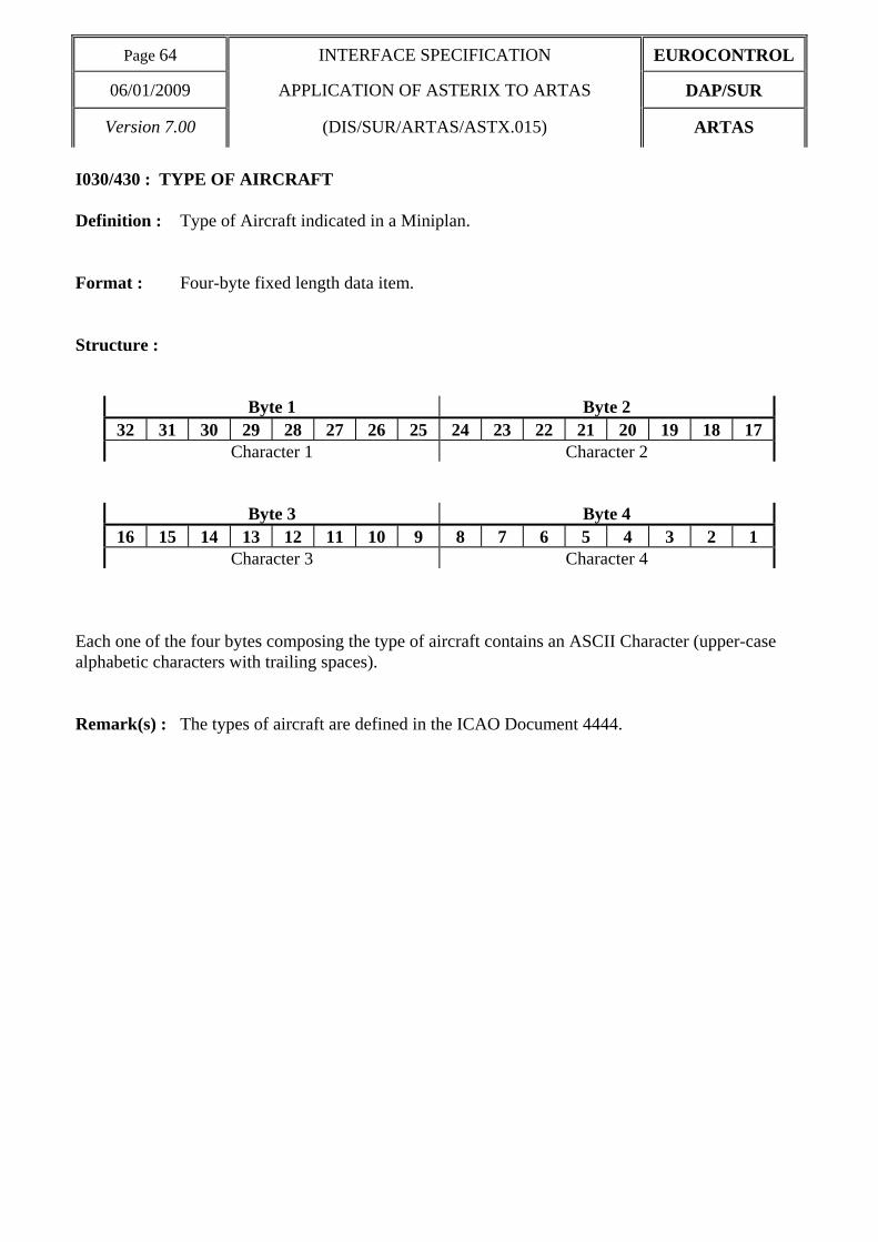
I030/430 : TYPE OF AIRCRAFT Definition : Type of Aircraft indicated in a Miniplan. Format : Four-byte fixed length data item. Structure :
Byte 1 Byte 2 32 31 30 29 28 27 26 25 24 23 22 21 20 19 18 17
Character 1 Character 2
Byte 3 Byte 4 16 15 14 13 12 11 10 9 8 7 6 5 4 3 2 1
Character 3 Character 4 Each one of the four bytes composing the type of aircraft contains an ASCII Character (upper-case alphabetic characters with trailing spaces). Remark(s) : The types of aircraft are defined in the ICAO Document 4444.

EUROCONTROL INTERFACE SPECIFICATION Page 65
DAP/SUR APPLICATION OF ASTERIX TO ARTAS 06/01/2009
ARTAS (DIS/SUR/ARTAS.ASTX.015) Version 7.00
I030/435 : CATEGORY OF TURBULENCE Definition : Category of turbulence of an aircraft (information provided in the Miniplan). Format : 1-byte fixed length data item. Structure :
Byte 1 8 7 6 5 4 3 2 1
TURBULENCE CATEGORY bits 8/1 TURBULENCE CATEGORY is an ASCII character code which may have the following
values : 1001100 = L : Light 1001101 = M : Medium 1001000 = H : Heavy 1001010 = J : Super Remark(s) :

Page 66 INTERFACE SPECIFICATION EUROCONTROL
06/01/2009 APPLICATION OF ASTERIX TO ARTAS DAP/SUR
Version 7.00 (DIS/SUR/ARTAS/ASTX.015) ARTAS
I030/440 : DEPARTURE AIRPORT Definition : Departure Airport indicated in a Miniplan. Format : Four-byte fixed length data item. Structure :
Byte 1 Byte 2 32 31 30 29 28 27 26 25 24 23 22 21 20 19 18 17
Character 1 Character 2
Byte 3 Byte 4 16 15 14 13 12 11 10 9 8 7 6 5 4 3 2 1
Character 3 Character 4 Each one of the four bytes composing the name of an airport contains an ASCII Character (upper-case alphabetic). Remark(s) : The Airport Names are indicated in the ICAO Location Indicators book.

EUROCONTROL INTERFACE SPECIFICATION Page 67
DAP/SUR APPLICATION OF ASTERIX TO ARTAS 06/01/2009
ARTAS (DIS/SUR/ARTAS.ASTX.015) Version 7.00
I030/450 : DESTINATION AIRPORT Definition : Destination Airport indicated in a Miniplan. Format : Four-byte fixed length data item. Structure :
Byte 1 Byte 2 32 31 30 29 28 27 26 25 24 23 22 21 20 19 18 17
Character 1 Character 2
Byte 3 Byte 4 16 15 14 13 12 11 10 9 8 7 6 5 4 3 2 1
Character 3 Character 4 Each one of the four bytes composing the name of an airport contains an ASCII Character (upper-case alphabetic). Remark(s) : the Airport Names are indicated in the ICAO Location Indicators book.

Page 68 INTERFACE SPECIFICATION EUROCONTROL
06/01/2009 APPLICATION OF ASTERIX TO ARTAS DAP/SUR
Version 7.00 (DIS/SUR/ARTAS/ASTX.015) ARTAS
I030/460 : ALLOCATED SSR CODES Definition : List of successive SSR codes allocated to a flight (Information provided in the
miniplan). Format : Repetitive data item, starting with a one-byte Repetition Factor indicating the number
of items, followed by series of 2-byte (Mode A codes) as necessary. Structure :
Byte 1 24 23 22 21 20 19 18 17
Repetition Factor
Byte 2 Byte 3 16 15 14 13 12 11 10 9 8 7 6 5 4 3 2 1
sb OCT1 OCT2 OCT3 OCT4 Repetition Factor = 1 to 5 bits 16/13 (sb) spare bits set to 0 bits 12/1 Mode 3/A Code under the form of 4 digits in octal representation : bits 12/10 : OCT1 = 1st octal digit, bits 9/7 : OCT2 = 2nd octal digit, bits 6/4 : OCT3 = 3rd octal digit, bits 3/1 : OCT4 = 4th octal digit, Remark(s) :

EUROCONTROL INTERFACE SPECIFICATION Page 69
DAP/SUR APPLICATION OF ASTERIX TO ARTAS 06/01/2009
ARTAS (DIS/SUR/ARTAS.ASTX.015) Version 7.00
I030/480 : CURRENT CLEARED FLIGHT LEVEL Definition : Current Cleared Flight Level of an aircraft, provided by a FPPS. Format : Two-byte fixed length data item. Structure :
Byte 1 Byte 2 16 15 14 13 12 11 10 9 8 7 6 5 4 3 2 1
LSB bit 1 (LSB) = 1/4 FL = 25 feet Remark(s) :

Page 70 INTERFACE SPECIFICATION EUROCONTROL
06/01/2009 APPLICATION OF ASTERIX TO ARTAS DAP/SUR
Version 7.00 (DIS/SUR/ARTAS/ASTX.015) ARTAS
I030/490 : CURRENT CONTROL POSITION Definition : Identification of the Current Control Position in charge of an aircraft, as provided by a
FPPS. Format : Two-byte fixed length data item. Structure :
Byte 1 Byte 2 16 15 14 13 12 11 10 9 8 7 6 5 4 3 2 1
CENTRE POSITION bits 16/9 (CENTRE) 8-bit group identification code (0 → 255) bits 8/1 (POSITION) 8-bit Control Position identification code (0 → 255) Remark(s) : the centre and the control position identification codes have to be defined between
communication partners.

EUROCONTROL INTERFACE SPECIFICATION Page 71
DAP/SUR APPLICATION OF ASTERIX TO ARTAS 06/01/2009
ARTAS (DIS/SUR/ARTAS.ASTX.015) Version 7.00
I030/RE : RESERVED EXPANSION DATA FIELD Definition : Field used to introduce intermediate changes for elementary surveillance. Format : One byte length field, followed by a two byte fixed length data item. Structure :
Byte 1 8 7 6 5 4 3 2 1
LENGTH LSB Bits 8/1 (LENGTH) Length of the Reserved Expansion Data Field in bytes including the length indicator.
Byte 2 Byte 3 16 15 14 13 12 11 10 9 8 7 6 5 4 3 2 1
MSA LSB MAI LSB
bits 16/9 (MSA) Age of the last Mode S Address used to update the track. bit 9 (LSB) = 1/4 s maximum value = 63.75 s bits 8/1 (MAI) Age of the last Mode S Aircraft Identification used to update the track. bit 1 (LSB) = 1/4 s maximum value = 63.75 s Remark(s) : The age is counted from I030/070 TIME OF LAST UPDATE, using the following
formula : age = I030/070 - time of last update (from item I030/382 for MSA and I030/384 for MAI).
If the computed age is greater than the maximum value or if the associated information has never been received, then the maximum value is returned.
If the computed age is negative, then 0 is returned.

Page 72 INTERFACE SPECIFICATION EUROCONTROL
06/01/2009 APPLICATION OF ASTERIX TO ARTAS DAP/SUR
Version 7.00 (DIS/SUR/ARTAS/ASTX.015) ARTAS
2.3 User Application Profile for ARTAS Users As it is defined in the ARTAS specification, the so-called Item Selector associated to a given service is used to define the track information messages for the service in question, selecting out of the items composing an ARTAS track. These items are defined in CATEGORY 030 (Exchange of Air Situation Pictures). The following User Application Profile shown in Table 3 shall be used for the transmission of Air Situation Picture to the Users.
Table 3 - Track Information UAP
FRN Data Item Information Length 1 I030/010 SERVER IDENTIFICATION TAG 2 2 I030/015 USER NUMBER 2 3 I030/030 SERVICE IDENTIFICATION 1+
(1x1) 4 I030/035 TYPE OF MESSAGE 1 5 I030/040 TRACK NUMBER 2 6 I030/070 TIME OF LAST UPDATE 3 7 I030/170 TRACK AGES 4
FX - Field extension indicator - 8 I030/100 CALCULATED TRACK POSITION (CARTESIAN) 4 9 I030/180 CALCULATED TRACK VELOCITY (POLAR) 4 10 I030/181 CALCULATED TRACK VELOCITY (CARTESIAN) 4 11 I030/060 TRACK MODE 3/A 2 12 I030/150 MEASURED TRACK MODE C 2 13 I030/130 CALCULATED TRACK ALTITUDE 2 14 I030/160 CALCULATED TRACK FLIGHT LEVEL 2 FX - Field extension indicator -
15 I030/080 ARTAS TRACK STATUS 0≤n≤3 1+(nx1)16 I030/090 ARTAS TRACK QUALITY 1 17 I030/200 MODE OF FLIGHT 1 18 I030/220 CALCULATED RATE OF CLIMB/DESCENT 2 19 I030/240 CALCULATED RATE OF TURN 1 20 I030/290 PLOT AGES 2 21 I030/260 RADAR IDENTIFICATION TAG 2 FX - Field extension indicator -

EUROCONTROL INTERFACE SPECIFICATION Page 73
DAP/SUR APPLICATION OF ASTERIX TO ARTAS 06/01/2009
ARTAS (DIS/SUR/ARTAS.ASTX.015) Version 7.00
FRN Data Item Information Length
22 I030/360 MEASURED POSITION 4 23 I030/140 LAST MEASURED MODE C 2 24 I030/340 LAST MEASURED MODE 3/A 2 25 I030/RE RESERVED EXPANSION DATA FIELD 3 26 I030/390 FPPS IDENTIFICATION TAG 2 27 I030/400 CALLSIGN 7 28 I030/410 PLN NUMBER 2 FX - Field extension indicator -
29 I030/440 DEPARTURE AIRPORT 4 30 I030/450 DESTINATION AIRPORT 4 31 I030/435 CATEGORY OF TURBULENCE 1 32 I030/430 TYPE OF AIRCRAFT 4 33 I030/460 ALLOCATED SSR CODES 1≤n≤5 1+(nx2)34 I030/480 CURRENT CLEARED FLIGHT LEVEL 2 35 I030/420 FLIGHT CATEGORY 1 FX - Field extension indicator -
36 I030/490 CURRENT CONTROL POSITION 2 37 I030/020 TIME OF MESSAGE 3 38 I030/382 AIRCRAFT ADDRESS 3 39 I030/384 AIRCRAFT IDENTIFICATION 6 40 I030/386 COMMUNICATIONS CAPABILITY AND FLIGHT STATUS 1 41 I030/110 ESTIMATED ACCURACY OF TRACK POSITION (CARTESIAN) 4 42 I030/190 ESTIMATED ACCURACY OF TRACK VELOCITY (POLAR) 4 FX - Field extension indicator -
43 I030/191 ESTIMATED ACCURACY OF TRACK VELOCITY (CARTESIAN) 4 44 I030/135 ESTIMATED ACCURACY OF TRACK ALTITUDE 2 45 I030/165 ESTIMATED ACCURACY OF CALCULATED TRACK FLIGHT LEVEL 2 46 I030/230 ESTIMATED ACCURACY OF RATE OF CLIMB/DESCENT 2 47 I030/250 ESTIMATED ACCURACY OF RATE OF TURN 1 48 I030/210 MODE OF FLIGHT PROBABILITIES 3 49 I030/120 TRACK MODE 2 CODE 2 FX - Field extension indicator -
50 I030/050 ARTAS TRACK NUMBER 0≤n≤5 3+(nx3)51 I030/270 LOCAL TRACK NUMBER 2 52 I030/370 MEASURED 3-D HEIGHT 2 53 - - 54 - - 55 - - 56 I030/RE Reserved Expansion Field 1+ FX - Field extension indicator -
In the above table, the third column gives the format and the length of each Data Item.

Page 74 INTERFACE SPECIFICATION EUROCONTROL
06/01/2009 APPLICATION OF ASTERIX TO ARTAS DAP/SUR
Version 7.00 (DIS/SUR/ARTAS/ASTX.015) ARTAS
. A stand-alone figure indicates the byte-count of a fixed length Data item, . j+(nxi) indicates a variable length Data item comprising a first part of j-bytes followed by an
extension of up to n times i-bytes (n determined by the amount of information to be transmitted),
. j+ alone indicates that the item has been designed as a variable length data item in anticipation
of future possible extensions.

EUROCONTROL INTERFACE SPECIFICATION Page 75
DAP/SUR APPLICATION OF ASTERIX TO ARTAS 06/01/2009
ARTAS (DIS/SUR/ARTAS.ASTX.015) Version 7.00
2.4 Encoding recommendations 1. Data Item 030/010 (SERVER IDENTIFICATION TAG) will have to be transmitted to identify
the data source in the frame of a broadcast service. 2. Data Item 030/030 (SERVICE IDENTIFICATION) may be transmitted with each track to
identify which elementary services of a combined service is concerned.

Page 76 INTERFACE SPECIFICATION EUROCONTROL
06/01/2009 APPLICATION OF ASTERIX TO ARTAS DAP/SUR
Version 7.00 (DIS/SUR/ARTAS/ASTX.015) ARTAS
2.5 Special Purpose Data Item of Category 62 ARTAS uses the Special Purpose data item of category 62 to provide a series of Target Report Identifiers. Each identifier is a four byte unsigned integer generated by ARTAS based solely on the data contained within the target reports used to update the track. The target report identifier is the result of the concatenation of the 1st, 5th, 9th, and 13th byte of the MD5 message digest algorithm of the input target report. Due to the non zero risk of having identical identifiers generated for different target reports; it is recommended that external analysis tools exploiting target report identifiers perform coherency checks on position and time. The target report with smallest delta with respect to the track update concerned shall be selected.

EUROCONTROL INTERFACE SPECIFICATION Page 77
DAP/SUR APPLICATION OF ASTERIX TO ARTAS 06/01/2009
ARTAS (DIS/SUR/ARTAS.ASTX.015) Version 7.00
I062/SP : TARGET REPORT IDENTIFIERS Definition : List of identifiers for each NN plot/target report used in the updating of the track since
it was last served. Format : A one byte length field, followed by a repetitive data item, starting with a one-byte
Repetition Factor indicating the number of items, followed by series of 4-byte Target Report Identifiers as necessary.
Structure :
Byte 1 8 7 6 5 4 3 2 1
Length
Byte 1 40 39 38 37 36 35 34 33
Repetition Factor
Byte 2 Byte 3 32 31 30 29 28 27 26 25 24 23 22 21 20 19 18 17
Target Report
Byte 4 Byte 5 16 15 14 13 12 11 10 9 8 7 6 5 4 3 2 1
Identifier Bits 40/33 Repetition Factor = 1 to 10 bits 32/1 Target Report Identifier Remark(s) : If there are too many target reports used to all be listed, then the most recently used target reports shall be listed.

Page 78 INTERFACE SPECIFICATION EUROCONTROL
06/01/2009 APPLICATION OF ASTERIX TO ARTAS DAP/SUR
Version 7.00 (DIS/SUR/ARTAS/ASTX.015) ARTAS

EUROCONTROL INTERFACE SPECIFICATION Page 79
DAP/SUR APPLICATION OF ASTERIX TO ARTAS 06/01/2009
ARTAS (DIS/SUR/ARTAS.ASTX.015) Version 7.00
3 LAYOUT OF SENSOR INFORMATION MESSAGES The data CATEGORY 031 : SENSOR INFORMATION MESSAGES contains information related to the surveillance sensors used by ARTAS. The messages may either be transmitted in the point-to-point or in the broadcast mode. Only the radar sources are concerned. The list of radars connected to the Tracker and the calculated systematic errors can be served to users for e.g. supervision or radar fall-back systems. The relevant User Application Profile for the transmission of Sensor information is defined in section 3.3

Page 80 INTERFACE SPECIFICATION EUROCONTROL
06/01/2009 APPLICATION OF ASTERIX TO ARTAS DAP/SUR
Version 7.00 (DIS/SUR/ARTAS/ASTX.015) ARTAS
3.1 List of Data Items of CATEGORY 031 The data items which shall be used for the transmission of sensor information messages shall be that defined in Table 4 and are described in the following pages.
Table 4 - Data Items of Category 031
Data Item Reference Number
Description
System Units
I031/010 SERVER IDENTIFICATION TAG N.A. I031/015 USER NUMBER N.A. I031/020 TIME OF MESSAGE 1/128 s I031/030 SENSOR IDENTIFICATION TAG N.A. I031/040 SENSOR STATUS N.A. I031/050 TIME STAMPING BIAS ms I031/060 SSR RANGE GAIN AND BIAS 10-6, 1/128 NM I031/070 SSR AZIMUTH BIAS 0.0055° I031/080 PR RANGE GAIN AND BIAS 10-6, 1/128 NM I031/090 PR AZIMUTH BIAS 0.0055°
N.A. = Not Applicable

EUROCONTROL INTERFACE SPECIFICATION Page 81
DAP/SUR APPLICATION OF ASTERIX TO ARTAS 06/01/2009
ARTAS (DIS/SUR/ARTAS.ASTX.015) Version 7.00
3.2 Description of Data Items of CATEGORY 031
Page 82 INTERFACE SPECIFICATION EUROCONTROL
06/01/2009 APPLICATION OF ASTERIX TO ARTAS DAP/SUR
Version 7.00 (DIS/SUR/ARTAS/ASTX.015) ARTAS
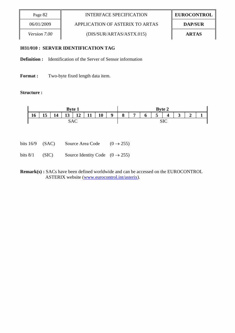
I031/010 : SERVER IDENTIFICATION TAG Definition : Identification of the Server of Sensor information Format : Two-byte fixed length data item. Structure :
Byte 1 Byte 2 16 15 14 13 12 11 10 9 8 7 6 5 4 3 2 1
SAC SIC bits 16/9 (SAC) Source Area Code (0 → 255) bits 8/1 (SIC) Source Identity Code (0 → 255) Remark(s) : SACs have been defined worldwide and can be accessed on the EUROCONTROL
ASTERIX website (www.eurocontrol.int/asterix).

EUROCONTROL INTERFACE SPECIFICATION Page 83
DAP/SUR APPLICATION OF ASTERIX TO ARTAS 06/01/2009
ARTAS (DIS/SUR/ARTAS.ASTX.015) Version 7.00
I031/015 : USER NUMBER Definition : Identification of the User of Sensor information Format : Two-byte fixed length data item. Structure :
Byte 1 Byte 2 16 15 14 13 12 11 10 9 8 7 6 5 4 3 2 1
USER NUMBER bits 16/1 (USER NUMBER) User number (0 → 16#FFFF#) Remark(s) : The User numbers are predefined in the User registration data base of the ARTAS Unit to which the User wants to connect.

Page 84 INTERFACE SPECIFICATION EUROCONTROL
06/01/2009 APPLICATION OF ASTERIX TO ARTAS DAP/SUR
Version 7.00 (DIS/SUR/ARTAS/ASTX.015) ARTAS
I031/020 : TIME OF MESSAGE Definition : Absolute time stamping of the message in the form of elapsed time since last midnight. Format : Three-byte fixed length data item. Structure :
Byte 1 24 23 22 21 20 19 18 17
Byte 2 Byte 3 16 15 14 13 12 11 10 9 8 7 6 5 4 3 2 1
LSB bit 1 (LSB) (2E-7) s = 1/128 s Remark(s) : This is the time at which a message is filled and not the time at which the data-block is
sent. The time of the day value is reset to 0 at every midnight.

EUROCONTROL INTERFACE SPECIFICATION Page 85
DAP/SUR APPLICATION OF ASTERIX TO ARTAS 06/01/2009
ARTAS (DIS/SUR/ARTAS.ASTX.015) Version 7.00
I031/030 : SENSOR IDENTIFICATION TAG Definition : Identification of the Sensor to which the provided information are related. Format : Two-byte fixed length data item. Structure :
Byte 1 Byte 2 16 15 14 13 12 11 10 9 8 7 6 5 4 3 2 1
SAC SIC bits 16/9 (SAC) Source Area Code (0 → 255) bits 8/1 (SIC) Source Identity Code (0 → 255) Remark(s) : SACs have been defined worldwide and can be accessed on the EUROCONTROL
ASTERIX website (www.eurocontrol.int/asterix).

Page 86 INTERFACE SPECIFICATION EUROCONTROL
06/01/2009 APPLICATION OF ASTERIX TO ARTAS DAP/SUR
Version 7.00 (DIS/SUR/ARTAS/ASTX.015) ARTAS
I031/040 : SENSOR STATUS Definition : Functioning status of the Sensor as monitored by ARTAS. Format : One-byte fixed length data item. Structure :
Byte 1 8 7 6 5 4 3 2 1
ST NP sb bits 8/6 (ST) Status of the radar = 000 Operational = 001 Degraded = 010 Initialization = 011 Initialization RMCDE = 100 Not Connected bit 5 (NP) No Plot Warning = 0 Default with no meaning. = 1 No plots being received bits 4/1 (sb) Spare bits set to 0 Remark(s) :

EUROCONTROL INTERFACE SPECIFICATION Page 87
DAP/SUR APPLICATION OF ASTERIX TO ARTAS 06/01/2009
ARTAS (DIS/SUR/ARTAS.ASTX.015) Version 7.00
I031/050 : TIME STAMPING BIAS Definition : Plot Time stamping bias Format : Two-byte fixed length data item. Structure :
Byte 1 Byte 2
16 15 14 13 12 11 10 9 8 7 6 5 4 3 2 1 sb TIME STAMPING BIAS LSB
bits 16/15 spare bits set to 0 bits 14/1 (TIME STAMPING BIAS) time stamping bias value bit 1 (LSB) = 1 ms Vmin = -5s Vmax = +5s Remark(s) :

Page 88 INTERFACE SPECIFICATION EUROCONTROL
06/01/2009 APPLICATION OF ASTERIX TO ARTAS DAP/SUR
Version 7.00 (DIS/SUR/ARTAS/ASTX.015) ARTAS
I031/060 : SSR RANGE GAIN AND BIAS Definition : SSR range gain and bias Format : Four-byte fixed length data item. Structure :
Byte 1 Byte 2
32 31 30 29 28 27 26 25 24 23 22 21 20 19 18 17 sb SSR RANGE BIAS LSB
Byte 3 Byte 4 16 15 14 13 12 11 10 9 8 7 6 5 4 3 2 1
SSR RANGE GAIN LSB bit 32 (sb) spare bit set to 0 bits 31/21 (SSR RANGE BIAS) SSR range bias bit 21 (LSB) = 1/128 NM Vmin = -5.4 NM Vmax = +5.4 NM bits 20/1 (SSR RANGE GAIN) SSR range gain bit 1 (LSB) = 10-6
Vmin = - 0.5 Vmax = + 0.5
Remark(s) :

EUROCONTROL INTERFACE SPECIFICATION Page 89
DAP/SUR APPLICATION OF ASTERIX TO ARTAS 06/01/2009
ARTAS (DIS/SUR/ARTAS.ASTX.015) Version 7.00
I031/070 : SSR AZIMUTH BIAS Definition : SSR azimuth bias Format : Two-byte fixed length data item. Structure :
Byte 1 Byte 2
16 15 14 13 12 11 10 9 8 7 6 5 4 3 2 1 SSR AZIMUTH BIAS LSB
bits 16/1 (SSR AZIMUTH BIAS) SSR azimuth bias bit 1 (LSB) = 360°/(216) ≅ 0.0055° Vmin = -180° Vmax = +180° - (360° / 216)
Remark(s) :

Page 90 INTERFACE SPECIFICATION EUROCONTROL
06/01/2009 APPLICATION OF ASTERIX TO ARTAS DAP/SUR
Version 7.00 (DIS/SUR/ARTAS/ASTX.015) ARTAS
I031/080 : PR RANGE GAIN AND BIAS Definition : PR range gain and bias Format : Four-byte fixed length data item. Structure :
Byte 1 Byte 2
32 31 30 29 28 27 26 25 24 23 22 21 20 19 18 17 sb PR RANGE BIAS LSB
Byte 3 Byte 4 16 15 14 13 12 11 10 9 8 7 6 5 4 3 2 1
PR RANGE GAIN LSB bit 32 (sb) spare bit set to 0 bits 31/21 (PR RANGE BIAS) PR range bias bit 21 (LSB) = 1/128 NM Vmin = -5.4 NM Vmax = +5.4 NM bits 20/1 (PR RANGE GAIN) PR range gain bit 1 (LSB) = 10-6
Vmin = - 0.5 Vmax = + 0.5
Remark(s) :

EUROCONTROL INTERFACE SPECIFICATION Page 91
DAP/SUR APPLICATION OF ASTERIX TO ARTAS 06/01/2009
ARTAS (DIS/SUR/ARTAS.ASTX.015) Version 7.00
I031/090 : PR AZIMUTH BIAS Definition : PR azimuth bias Format : Two-byte fixed length data item. Structure :
Byte 1 Byte 2
16 15 14 13 12 11 10 9 8 7 6 5 4 3 2 1 PR AZIMUTH BIAS LSB
bits 16/1 (PR AZIMUTH BIAS) PR azimuth bias bit 1 (LSB) = 360°/(216) ≅ 0.0055° Vmin = -180° Vmax = +180°- (360° / 216)
Remark(s) :

Page 92 INTERFACE SPECIFICATION EUROCONTROL
06/01/2009 APPLICATION OF ASTERIX TO ARTAS DAP/SUR
Version 7.00 (DIS/SUR/ARTAS/ASTX.015) ARTAS
3.3 User Application Profile for the transmission of Sensor information The following User Application Profile shown in Table 5 shall be used for the transmission of Sensor information messages.
Table 5 - Sensor Information (CAT 031) UAP
FRN Data Item Information Length 1 I031/010 SERVER IDENTIFICATION TAG 2 2 I031/015 USER NUMBER 2 3 I031/020 TIME OF MESSAGE 3 4 I031/030 SENSOR IDENTIFICATION TAG 2 5 I031/040 SENSOR STATUS 1 6 I031/050 TIME STAMPING BIAS 2 7 I031/060 SSR RANGE GAIN AND BIAS 4
FX - Field extension indicator - 8 I031/070 SSR AZIMUTH BIAS 2 9 I031/080 PR RANGE GAIN AND BIAS 4 10 I031/090 PR AZIMUTH BIAS 2 11 - 12 - 13 - 14 - FX - Field extension indicator -
In the above table, the third column gives the format and the length of each Data Item. . A stand-alone figure indicates the byte-count of a fixed length Data item, . j+(nxi) indicates a variable length Data item comprising a first part of j-bytes followed by an
extension of up to n times i-bytes (n determined by the amount of information to be transmitted).

EUROCONTROL INTERFACE SPECIFICATION Page 93
DAP/SUR APPLICATION OF ASTERIX TO ARTAS 06/01/2009
ARTAS (DIS/SUR/ARTAS.ASTX.015) Version 7.00
3.4 Encoding recommendations 1. Data Item 031/010 (SERVER IDENTIFICATION TAG) will have to be transmitted to identify
the data source in the frame of a broadcast service.

Page 94 INTERFACE SPECIFICATION EUROCONTROL
06/01/2009 APPLICATION OF ASTERIX TO ARTAS DAP/SUR
Version 7.00 (DIS/SUR/ARTAS/ASTX.015) ARTAS
4 LAYOUT OF MESSAGES PROVIDED BY USERS TO ARTAS The data CATEGORY 032 is used for the transmission of data from Users to ARTAS. Such information will be related to the so-called track enrichment, i.e. the addition of supplementary information to the ARTAS Tracks. The messages may only be sent to ARTAS in the point to point mode. Up to now, only one type of system is concerned : the Flight Plan Data Processing System(s) that will provide ARTAS with the so-called Miniplan(s), used for the track labelling.

EUROCONTROL INTERFACE SPECIFICATION Page 95
DAP/SUR APPLICATION OF ASTERIX TO ARTAS 06/01/2009
ARTAS (DIS/SUR/ARTAS.ASTX.015) Version 7.00
4.1 List of Data Items of CATEGORY 032 The data items which shall be used for the transmission of information by users to ARTAS shall be that defined in Table 6 and described in the following pages.
Table 6 - Data Items of Category 032
Data Item Reference Number
Description
System Units
I032/010 SERVER IDENTIFICATION TAG N.A. I032/015 USER NUMBER N.A. I032/018 DATA SOURCE IDENTIFICATION TAG N.A. I032/020 TIME OF MESSAGE 1/128 s I032/035 TYPE OF MESSAGE N.A. I032/040 TRACK NUMBER N.A. I032/050 ARTAS TRACK NUMBER N.A. I032/060 TRACK MODE 3/A N.A. I032/400 CALLSIGN N.A. I032/410 PLN NUMBER N.A. I032/420 FLIGHT CATEGORY N.A. I032/430 TYPE OF AIRCRAFT N.A. I032/435 CATEGORY OF TURBULENCE N.A. I032/440 DEPARTURE AIRPORT N.A. I032/450 DESTINATION AIRPORT N.A. I032/460 ALLOCATED SSR CODES N.A. I032/480 CURRENT CLEARED FLIGHT LEVEL 1/4 FL I032/490 CURRENT CONTROL POSITION N.A. I032/500 SUPPLEMENTARY FLIGHT DATA N.A
N.A. = Not Applicable

Page 96 INTERFACE SPECIFICATION EUROCONTROL
06/01/2009 APPLICATION OF ASTERIX TO ARTAS DAP/SUR
Version 7.00 (DIS/SUR/ARTAS/ASTX.015) ARTAS
4.2 Description of Data Items of CATEGORY 032

EUROCONTROL INTERFACE SPECIFICATION Page 97
DAP/SUR APPLICATION OF ASTERIX TO ARTAS 06/01/2009
ARTAS (DIS/SUR/ARTAS.ASTX.015) Version 7.00
I032/010 : SERVER IDENTIFICATION TAG Definition : Identification of the Server of track information. Format : Two-byte fixed length data item. Structure :
Byte 1 Byte 2 16 15 14 13 12 11 10 9 8 7 6 5 4 3 2 1
SAC SIC bits 16/9 (SAC) Source Area Code (0 → 255) bits 8/1 (SIC) Source Identity Code (0 → 255) Remark(s) : In the case of miniplan exchange between ARTAS units, the Server Identification Tag
corresponds to the sender of the miniplan.
SACs have been defined worldwide and can be accessed on the EUROCONTROL ASTERIX website (www.eurocontrol.int/asterix).

Page 98 INTERFACE SPECIFICATION EUROCONTROL
06/01/2009 APPLICATION OF ASTERIX TO ARTAS DAP/SUR
Version 7.00 (DIS/SUR/ARTAS/ASTX.015) ARTAS
I032/015 : USER NUMBER Definition : Identification of the User of track information Format : Two-byte fixed length data item. Structure :
Byte 1 Byte 2 16 15 14 13 12 11 10 9 8 7 6 5 4 3 2 1
USER NUMBER bits 16/1 (USER NUMBER) User number (0 → 16#FFFF#) Remark(s) : The User numbers are predefined in the User registration data base of the ARTAS Unit to which the User wants to connect. In the case of miniplan exchange between ARTAS units, the User Number corresponds to the receiver of the miniplan.

EUROCONTROL INTERFACE SPECIFICATION Page 99
DAP/SUR APPLICATION OF ASTERIX TO ARTAS 06/01/2009
ARTAS (DIS/SUR/ARTAS.ASTX.015) Version 7.00
I032/018 : DATA SOURCE IDENTIFICATION TAG Definition : Identification of the data source (system) from which the information contained in the
message was originated. Format : Two-byte fixed length data item. Structure :
Byte 1 Byte 2 16 15 14 13 12 11 10 9 8 7 6 5 4 3 2 1
SAC SIC bits 16/9 (SAC) Source Area Code (0 → 255) bits 8/1 (SIC) Source Identity Code (0 → 255) Remark(s) : This item will be used if the system sending the miniplan information (i.e. the system
which is identified in I032/015 : USER NUMBER) is another system than the FPPS from which the miniplan information has been received. This will be the case of e.g. an ARTAS unit forwarding miniplan information to an adjacent unit.
SACs have been defined worldwide and can be accessed on the EUROCONTROL ASTERIX website (www.eurocontrol.int/asterix).
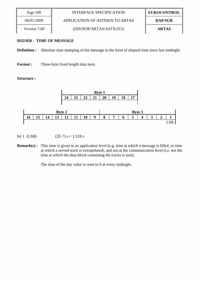
Page 100 INTERFACE SPECIFICATION EUROCONTROL
06/01/2009 APPLICATION OF ASTERIX TO ARTAS DAP/SUR
Version 7.00 (DIS/SUR/ARTAS/ASTX.015) ARTAS
I032/020 : TIME OF MESSAGE Definition : Absolute time stamping of the message in the form of elapsed time since last midnight. Format : Three-byte fixed length data item. Structure :
Byte 1 24 23 22 21 20 19 18 17
Byte 2 Byte 3 16 15 14 13 12 11 10 9 8 7 6 5 4 3 2 1
LSB bit 1 (LSB) (2E-7) s = 1/128 s Remark(s) : This time is given at an application level (e.g. time at which a message is filled, or time
at which a served track is extrapolated), and not at the communication level (i.e. not the time at which the data-block containing the tracks is sent). The time of the day value is reset to 0 at every midnight.

EUROCONTROL INTERFACE SPECIFICATION Page 101
DAP/SUR APPLICATION OF ASTERIX TO ARTAS 06/01/2009
ARTAS (DIS/SUR/ARTAS.ASTX.015) Version 7.00
I032/035 : TYPE OF MESSAGE Definition : This data item allows for a more convenient handling of the message at the receiver
side by further defining the type of transaction. Format : One-byte fixed length data item. Structure :
Byte 1 8 7 6 5 4 3 2 1
FAMILY NATURE bits 8/5 (FAMILY) to which the message belongs (0 to 15), bits 4/1 (NATURE) of the message (within its FAMILY) (0 to 15). FAMILY = 1 : information sent by a FPPS : (NATURE) = 1 Flight Plan to track initial correlation 2 Miniplan update 3 End of correlation 4 Miniplan Cancellation Remark(s) : The composition of the messages are described by the UAP attached to each FAMILY.
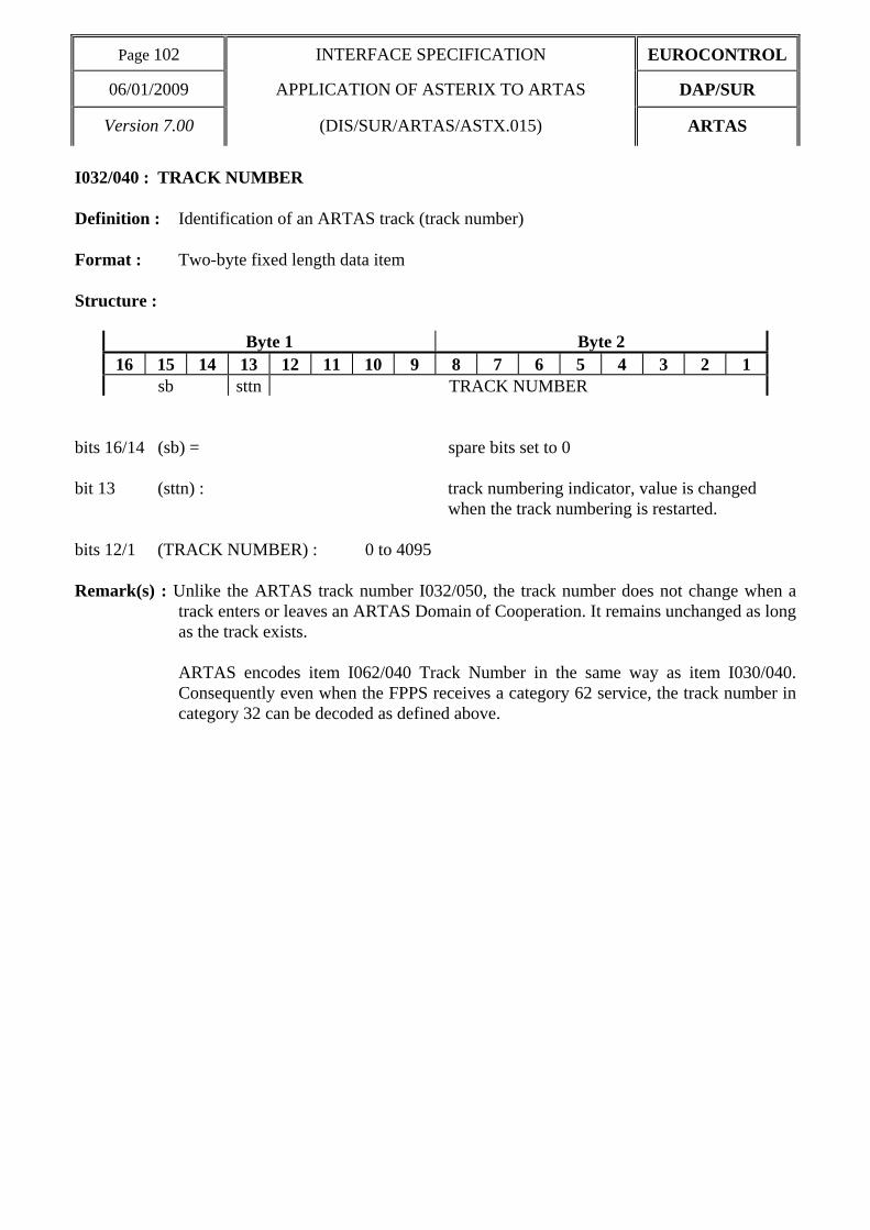
Page 102 INTERFACE SPECIFICATION EUROCONTROL
06/01/2009 APPLICATION OF ASTERIX TO ARTAS DAP/SUR
Version 7.00 (DIS/SUR/ARTAS/ASTX.015) ARTAS
I032/040 : TRACK NUMBER Definition : Identification of an ARTAS track (track number) Format : Two-byte fixed length data item Structure :
Byte 1 Byte 2 16 15 14 13 12 11 10 9 8 7 6 5 4 3 2 1
sb sttn TRACK NUMBER bits 16/14 (sb) = spare bits set to 0 bit 13 (sttn) : track numbering indicator, value is changed
when the track numbering is restarted. bits 12/1 (TRACK NUMBER) : 0 to 4095 Remark(s) : Unlike the ARTAS track number I032/050, the track number does not change when a
track enters or leaves an ARTAS Domain of Cooperation. It remains unchanged as long as the track exists.
ARTAS encodes item I062/040 Track Number in the same way as item I030/040.
Consequently even when the FPPS receives a category 62 service, the track number in category 32 can be decoded as defined above.
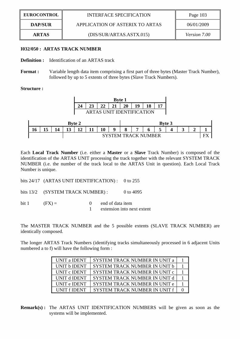
EUROCONTROL INTERFACE SPECIFICATION Page 103
DAP/SUR APPLICATION OF ASTERIX TO ARTAS 06/01/2009
ARTAS (DIS/SUR/ARTAS.ASTX.015) Version 7.00
I032/050 : ARTAS TRACK NUMBER Definition : Identification of an ARTAS track Format : Variable length data item comprising a first part of three bytes (Master Track Number),
followed by up to 5 extents of three bytes (Slave Track Numbers). Structure :
Byte 1 24 23 22 21 20 19 18 17
ARTAS UNIT IDENTIFICATION
Byte 2 Byte 3 16 15 14 13 12 11 10 9 8 7 6 5 4 3 2 1
SYSTEM TRACK NUMBER FX Each Local Track Number (i.e. either a Master or a Slave Track Number) is composed of the identification of the ARTAS UNIT processing the track together with the relevant SYSTEM TRACK NUMBER (i.e. the number of the track local to the ARTAS Unit in question). Each Local Track Number is unique. bits 24/17 (ARTAS UNIT IDENTIFICATION) : 0 to 255 bits 13/2 (SYSTEM TRACK NUMBER) : 0 to 4095 bit 1 (FX) = 0 end of data item 1 extension into next extent The MASTER TRACK NUMBER and the 5 possible extents (SLAVE TRACK NUMBER) are identically composed. The longer ARTAS Track Numbers (identifying tracks simultaneously processed in 6 adjacent Units numbered a to f) will have the following form :
UNIT a IDENT SYSTEM TRACK NUMBER IN UNIT a 1 UNIT b IDENT SYSTEM TRACK NUMBER IN UNIT b 1 UNIT c IDENT SYSTEM TRACK NUMBER IN UNIT c 1 UNIT d IDENT SYSTEM TRACK NUMBER IN UNIT d 1 UNIT e IDENT SYSTEM TRACK NUMBER IN UNIT e 1 UNIT f IDENT SYSTEM TRACK NUMBER IN UNIT f 0
Remark(s) : The ARTAS UNIT IDENTIFICATION NUMBERS will be given as soon as the
systems will be implemented.

Page 104 INTERFACE SPECIFICATION EUROCONTROL
06/01/2009 APPLICATION OF ASTERIX TO ARTAS DAP/SUR
Version 7.00 (DIS/SUR/ARTAS/ASTX.015) ARTAS
I032/060 : TRACK MODE 3/A Definition : Mode 3/A identity associated to the track Format : Two-bytes fixed length data item. Structure :
Byte 1 Byte 2 16 15 14 13 12 11 10 9 8 7 6 5 4 3 2 1
sb OCT1 OCT2 OCT3 OCT4 bit 16/13 (sb) spare bits set to 0 bits 12/1 Mode 3/A Code under the form of 4 digits in octal representation : bits 12/10 : OCT1 = 1st octal digit, bits 9/7 : OCT2 = 2nd octal digit, bits 6/4 : OCT3 = 3rd octal digit, bits 3/1 : OCT4 = 4th octal digit, Remark(s) :

EUROCONTROL INTERFACE SPECIFICATION Page 105
DAP/SUR APPLICATION OF ASTERIX TO ARTAS 06/01/2009
ARTAS (DIS/SUR/ARTAS.ASTX.015) Version 7.00
I032/400 : CALLSIGN Definition : Callsign (in 7 characters) of an aircraft (provided in the Miniplan). Format : Seven-bytes fixed length data item. Structure :
Byte 1 56 55 54 53 52 51 50 49
Character 1
Byte 2 Byte 3 48 47 46 45 44 43 42 41 40 39 38 37 36 35 34 33
Character 2 Character 3
Byte 4 Byte 5 32 31 30 29 28 27 26 25 24 23 22 21 20 19 18 17
Character 4 Character 5
Byte 6 Byte 7 16 15 14 13 12 11 10 9 8 7 6 5 4 3 2 1
Character 6 Character 7 Each one of the seven bytes contains an ASCII Character. The CALLSIGN is always left adjusted. It contains up to 7 upper-case alphanumeric characters, the remaining character positions (if any) are padded with space characters. Remark(s) :

Page 106 INTERFACE SPECIFICATION EUROCONTROL
06/01/2009 APPLICATION OF ASTERIX TO ARTAS DAP/SUR
Version 7.00 (DIS/SUR/ARTAS/ASTX.015) ARTAS
I032/410 : PLN NUMBER Definition : The PLN NUMBER is an integer value representing a unique reference to a Flight-
plan record within a particular FPPS (Information provided in the miniplan). Format : Two-byte fixed length data item. Structure :
Byte 1 Byte 2 16 15 14 13 12 11 10 9 8 7 6 5 4 3 2 1
PLN NUMBER LSB
Maximum value = 65535 Remark(s) :

EUROCONTROL INTERFACE SPECIFICATION Page 107
DAP/SUR APPLICATION OF ASTERIX TO ARTAS 06/01/2009
ARTAS (DIS/SUR/ARTAS.ASTX.015) Version 7.00
I032/420 : FLIGHT CATEGORY Definition : Flight Category (information provided in the Miniplan). Format : One-byte fixed length data item. Structure :
Byte 1 8 7 6 5 4 3 2 1
OAT GAT FR1 FR2 SP3 SP2 SP1 sb bits 8/7 (GAT/OAT) 00 Unknown 01 General Air Traffic 10 Operational Air Traffic 11 Not applicable bits 6/5 (FR1/FR2) 00 Instrument Flight Rules 01 Visual Flight rules 10 Not applicable 11 Controlled Visual Flight Rules bits 4/2 (SP3/SP2/SP1) These three bits allow for the definition of up to 7 sub-categories
within the main categories. bit 1 (sb) spare bits set to 0 Remark(s) :

Page 108 INTERFACE SPECIFICATION EUROCONTROL
06/01/2009 APPLICATION OF ASTERIX TO ARTAS DAP/SUR
Version 7.00 (DIS/SUR/ARTAS/ASTX.015) ARTAS
I032/430 : TYPE OF AIRCRAFT Definition : Type of Aircraft indicated in a Miniplan. Format : Four-byte fixed length data item. Structure :
Byte 1 Byte 2 32 31 30 29 28 27 26 25 24 23 22 21 20 19 18 17
Character 1 Character 2
Byte 3 Byte 4 16 15 14 13 12 11 10 9 8 7 6 5 4 3 2 1
Character 3 Character 4 Each one of the four bytes composing the type of aircraft contains an ASCII Character (upper-case alphabetic characters with trailing spaces). Remark(s) : The types of aircraft are defined in the ICAO Document 4444.

EUROCONTROL INTERFACE SPECIFICATION Page 109
DAP/SUR APPLICATION OF ASTERIX TO ARTAS 06/01/2009
ARTAS (DIS/SUR/ARTAS.ASTX.015) Version 7.00
I032/435 : CATEGORY OF TURBULENCE Definition : Category of turbulence of an aircraft (information provided in the Miniplan). Format : 1-byte fixed length data item. Structure :
Byte 1 8 7 6 5 4 3 2 1
TURBULENCE CATEGORY bits 8/1 TURBULENCE CATEGORY is an ASCII character code which may have the following
values : 1001100 = L : light 1001101 = M : Medium 1001000 = H : Heavy 1001010 = J : Super Remark(s) :

Page 110 INTERFACE SPECIFICATION EUROCONTROL
06/01/2009 APPLICATION OF ASTERIX TO ARTAS DAP/SUR
Version 7.00 (DIS/SUR/ARTAS/ASTX.015) ARTAS
I032/440 : DEPARTURE AIRPORT Definition : Departure Airport indicated in a Miniplan. Format : Four-byte fixed length data item. Structure :
Byte 1 Byte 2 32 31 30 29 28 27 26 25 24 23 22 21 20 19 18 17
Character 1 Character 2
Byte 3 Byte 4 16 15 14 13 12 11 10 9 8 7 6 5 4 3 2 1
Character 3 Character 4 Each one of the four bytes composing the name of an airport contains an ASCII Character (upper-case alphabetic). Remark(s) : The Airport Names are indicated in the ICAO Location Indicators book.

EUROCONTROL INTERFACE SPECIFICATION Page 111
DAP/SUR APPLICATION OF ASTERIX TO ARTAS 06/01/2009
ARTAS (DIS/SUR/ARTAS.ASTX.015) Version 7.00
I032/450 : DESTINATION AIRPORT Definition : Destination Airport indicated in a Miniplan. Format : Four-byte fixed length data item. Structure :
Byte 1 Byte 2 32 31 30 29 28 27 26 25 24 23 22 21 20 19 18 17
Character 1 Character 2
Byte 3 Byte 4 16 15 14 13 12 11 10 9 8 7 6 5 4 3 2 1
Character 3 Character 4 Each one of the four bytes composing the name of an airport contains an ASCII Character (upper-case alphabetic). Remark(s) : the Airport Names are indicated in the ICAO Location Indicators book.

Page 112 INTERFACE SPECIFICATION EUROCONTROL
06/01/2009 APPLICATION OF ASTERIX TO ARTAS DAP/SUR
Version 7.00 (DIS/SUR/ARTAS/ASTX.015) ARTAS
I032/460 : ALLOCATED SSR CODES Definition : List of successive SSR codes allocated to a flight (Information provided in the
miniplan). Format : Repetitive data item, starting with a one-byte Repetition Factor indicating the number
of items, followed by series of 2-byte (Mode A codes) as necessary. Structure :
Byte 1 24 23 22 21 20 19 18 17
Repetition Factor
Byte 2 Byte 3 16 15 14 13 12 11 10 9 8 7 6 5 4 3 2 1
sb OCT1 OCT2 OCT3 OCT4 Repetition Factor = 1 to 5 bits 16/13 (sb) spare bits set to 0 bits 12/1 Mode 3/A Code under the form of 4 digits in octal representation : bits 12/10 : OCT1 = 1st octal digit, bits 9/7 : OCT2 = 2nd octal digit, bits 6/4 : OCT3 = 3rd octal digit, bits 3/1 : OCT4 = 4th octal digit, Remark(s) :

EUROCONTROL INTERFACE SPECIFICATION Page 113
DAP/SUR APPLICATION OF ASTERIX TO ARTAS 06/01/2009
ARTAS (DIS/SUR/ARTAS.ASTX.015) Version 7.00
I032/480 : CURRENT CLEARED FLIGHT LEVEL Definition : Current Cleared Flight Level of an aircraft, provided by a FPPS. Format : Two-bytes fixed length data item. Structure :
Byte 1 Byte 2 16 15 14 13 12 11 10 9 8 7 6 5 4 3 2 1
LSB bit 1 (LSB) = 1/4 FL = 25 feet Remark(s) :

Page 114 INTERFACE SPECIFICATION EUROCONTROL
06/01/2009 APPLICATION OF ASTERIX TO ARTAS DAP/SUR
Version 7.00 (DIS/SUR/ARTAS/ASTX.015) ARTAS
I032/490 : CURRENT CONTROL POSITION Definition : Identification of the Current Control Position in charge of an aircraft, as provided by a
FPPS. Format : Two-bytes fixed length data item. Structure :
Byte 1 Byte 2 16 15 14 13 12 11 10 9 8 7 6 5 4 3 2 1
CENTRE POSITION bits 16/9 (CENTRE) 8-bit group identification code (0 to 255) bits 8/1 (POSITION) 8-bit Control Position identification code (0 to 255) Remark(s) : the centre and the control position identification codes have to be defined between
communication partners.

EUROCONTROL INTERFACE SPECIFICATION Page 115
DAP/SUR APPLICATION OF ASTERIX TO ARTAS 06/01/2009
ARTAS (DIS/SUR/ARTAS.ASTX.015) Version 7.00
I032/500 : SUPPLEMENTARY FLIGHT DATA Definition : Flight related data provided by ground based systems. Format : Compound Data Item, comprising a primary subfield of up to two octets, followed by
the indicated subfields. Structure : Primary Subfield:
Byte 1 Byte 2
16 15 14 13 12 11 10 9 8 7 6 5 4 3 2 1 IFI RVP RDS TOD AST STS STD FX STA 0 0 0 0 0 0 FX
bit-16 (IFI) IFPS FLIGHT ID = 0 Absence of Subfield #1 = 1 Presence of Subfield #1 bit-15 (RVP) RVSM & Flight Priority = 0 Absence of Subfield #2 = 1 Presence of Subfield #2 bit-14 (RDS) Runway Designation = 0 Absence of Subfield #3 = 1 Presence of Subfield #3 bit-13 (TOD) Time of Departure / Arrival = 0 Absence of Subfield #4 = 1 Presence of Subfield #4 bit-12 (AST) Aircraft Stand = 0 Absence of Subfield #5 = 1 Presence of Subfield #5 bit-11 (STS) Stand Status = 0 Absence of Subfield #6 = 1 Presence of Subfield #6 bit-10 (STD) Standard Instrument Departure = 0 Absence of Subfield #7 = 1 Presence of Subfield #7 bit-9 FX Extension indicator = 0 no extension = 1 extension bit-8 (STA) Standard Instrument Arrival = 0 Absence of Subfield #8 = 1 Presence of Subfield #8 bits-7/2 Spare bits set to zero bit-1 FX Extension indicator = 0 no extension = 1 extension

Page 116 INTERFACE SPECIFICATION EUROCONTROL
06/01/2009 APPLICATION OF ASTERIX TO ARTAS DAP/SUR
Version 7.00 (DIS/SUR/ARTAS/ASTX.015) ARTAS
Structure of Subfield # 1: IFPS FLIGHT ID
Byte 1 Byte 2 32 31 30 29 28 27 26 25 24 23 22 21 20 19 18 17
TYP 0 0 0 NBR
Byte 3 Byte 4 16 15 14 13 12 11 10 9 8 7 6 5 4 3 2 1
bits-32/31 (TYP) = 00 Plan Number = 01 Unit 1 internal flight number = 10 Unit 2 internal flight number = 11 Unit 3 internal flight number bits-30/28 spare bits set to zero bits-27/1 (NBR) Number from 0 to 99 999 999
Structure of Subfield # 2: RVSM & Flight Priority
Byte 1
8 7 6 5 4 3 2 1 spare RVSM HPR
bits 8/4 Spare bits set to zero bits 3/2 (RVSM) = 00 Unknown = 01 Approved = 10 Exempt = 11 Not Approved bit 1 (HPR) = 0 Normal Priority Flight = 1 High Priority Flight

EUROCONTROL INTERFACE SPECIFICATION Page 117
DAP/SUR APPLICATION OF ASTERIX TO ARTAS 06/01/2009
ARTAS (DIS/SUR/ARTAS.ASTX.015) Version 7.00
Structure of Subfield # 3: Runway Designation
Byte 1 Byte 2 24 23 22 21 20 19 18 17 16 15 14 13 12 11 10 9
NU1 NU 2
Byte 3 8 7 6 5 4 3 2 1
LTR bits 24/17 (NU1) First number bits 16/9 (NU2) Second number bits 8/1 (LTR) Letter
Remark(s) : 1. NU1, NU2 and LTR each contain an ASCII character (upper-case alphabetic). 2. For details refer to ICAO Annex 14, chapter 5. Structure of Subfield # 4: Time of Departure / Arrival
Byte 1
40 39 38 37 36 35 34 33 REP
Byte 2 Byte 3
32 31 30 29 28 27 26 25 24 23 22 21 20 19 18 17 TYP DAY 0 0 0 0 HOR LSB
Byte 4 Byte 5 16 15 14 13 12 11 10 9 8 7 6 5 4 3 2 1 0 0 MIN LSB AVS 0 SEC LSB
bits-40/33 (REP) Repetition Factor bits-32/28 (TYP) = 0 Scheduled off-block time = 1 Estimated off-block time = 2 Estimated take-off time = 3 Actual off-block time = 4 Predicted time at runway hold = 5 Actual time at runway hold = 6 Actual line-up time = 7 Actual take-off time = 8 Estimated time of arrival

Page 118 INTERFACE SPECIFICATION EUROCONTROL
06/01/2009 APPLICATION OF ASTERIX TO ARTAS DAP/SUR
Version 7.00 (DIS/SUR/ARTAS/ASTX.015) ARTAS
= 9 Predicted landing time = 10 Actual landing time = 11 Actual time off runway = 12 Predicted time to gate = 13 Actual on-block time bits-27/26 (DAY) = 00 Today = 01 Yesterday = 10 Tomorrow = 11 Invalid bits-25/22 spare bits set to zero bits-21/17 (HOR) Hours, from 0 to 23 bits-16/15 spare bits set to zero bits-14/9 (MIN) Minutes, from 0 to 59 bit-8 (AVS) = 0 Seconds available = 1 Seconds not available bit-7 spare bits set to zero bits-6/1 (SEC) Seconds, from 0 to 59
Remark(s) : Estimated times are derived from flight plan systems. Predicted times are derived by the fusion system, based on surveillance data. For definitions, see [Ref.4]
Structure of Subfield # 5: Aircraft Stand
Byte 1 Byte 2 48 47 46 45 44 43 42 41 40 39 38 37 36 35 34 33
Character 1 Character 2
Byte 3 Byte 4 32 31 30 29 28 27 26 25 24 23 22 21 20 19 18 17
Character 3 Character 4
Byte 5 Byte 6 16 15 14 13 12 11 10 9 8 7 6 5 4 3 2 1
Character 5 Character 6 Remark(s) : Each one of the six Octets contains an ASCII Character. The Aircraft Stand identification is always left adjusted. It contains up to six upper-case alphanumeric characters, the remaining character positions (if any) are padded with space characters.
Structure of Subfield # 6: Stand Status

EUROCONTROL INTERFACE SPECIFICATION Page 119
DAP/SUR APPLICATION OF ASTERIX TO ARTAS 06/01/2009
ARTAS (DIS/SUR/ARTAS.ASTX.015) Version 7.00
Byte 1 8 7 6 5 4 3 2 1 EMP AVL 0 0 0 0
bits-8/7 (EMP) = 00 Empty = 01 Occupied = 10 Unknown = 11 Invalid bits-6/5 (AVL) = 00 Available = 01 Not available = 10 Unknown = 11 Invalid
Structure of Subfield # 7: Standard Instrument Departure
Byte 1 56 55 54 53 52 51 50 49
Character 1
Byte 2 Byte 3 48 47 46 45 44 43 42 41 40 39 38 37 36 35 34 33
Character 2 Character 3
Byte 4 Byte 5 32 31 30 29 28 27 26 25 24 23 22 21 20 19 18 17
Character 4 Character 5
Byte 6 Byte 7 16 15 14 13 12 11 10 9 8 7 6 5 4 3 2 1
Character 6 Character 7 Remarks: Each one of the seven Octets contains an ASCII Character. The SID is always left adjusted. It contains up to seven alphanumeric characters, the remaining character positions (if any) are padded with space characters.

Page 120 INTERFACE SPECIFICATION EUROCONTROL
06/01/2009 APPLICATION OF ASTERIX TO ARTAS DAP/SUR
Version 7.00 (DIS/SUR/ARTAS/ASTX.015) ARTAS
Structure of Subfield # 8: Standard Instrument Arrival
Byte 1 56 55 54 53 52 51 50 49
Character 1
Byte 2 Byte 3 48 47 46 45 44 43 42 41 40 39 38 37 36 35 34 33
Character 2 Character 3
Byte 4 Byte 5 32 31 30 29 28 27 26 25 24 23 22 21 20 19 18 17
Character 4 Character 5
Byte 6 Byte 7 16 15 14 13 12 11 10 9 8 7 6 5 4 3 2 1
Character 6 Character 7 Remarks: Each one of the seven Octets contains an ASCII Character. The STAR is always left adjusted. It contains up to seven alphanumeric characters, the remaining character positions (if any) are padded with space characters.

EUROCONTROL INTERFACE SPECIFICATION Page 121
DAP/SUR APPLICATION OF ASTERIX TO ARTAS 06/01/2009
ARTAS (DIS/SUR/ARTAS.ASTX.015) Version 7.00
4.3 User Application Profile for the transmission of Miniplans The following User Application Profile shown in Table 7 shall be used for the transmission of miniplans from an FPPS to ARTAS and between adjacent ARTAS Units.
Table 7 - UAP for the transmission of miniplans
FRN Data Item Information Length 1 I032/010 SERVER IDENTIFICATION TAG 2 2 I032/015 USER NUMBER 2 3 I032/018 DATA SOURCE IDENTIFICATION TAG 2 4 I032/035 TYPE OF MESSAGE 1 5 I032/020 TIME OF MESSAGE 3 6 I032/040 TRACK NUMBER 2 7 I032/050 ARTAS TRACK NUMBER 0≤n≤5 3+(nx3)
FX - field extension indicator - 8 I032/060 TRACK MODE 3/A 2 9 I032/400 CALLSIGN 7 10 I032/410 PLN NUMBER 2 11 I032/420 FLIGHT CATEGORY 1 12 I032/440 DEPARTURE AIRPORT 4 13 I032/450 DESTINATION AIRPORT 4 14 I032/480 CURRENT CLEARED FLIGHT LEVEL 2 FX - field extension indicator -
15 I032/490 CURRENT CONTROL POSITION 2 16 I032/430 TYPE OF AIRCRAFT 4 17 I032/435 CATEGORY OF TURBULENCE 1 18 I032/460 ALLOCATED SSR CODES 1≤n≤5 1+(nx2) 19 I032/500 SUPPLEMENTARY FLIGHT DATA 1+ 20 - - 21 I032/RE Reserved Expansion Field 1+ FX - field extension indicator -
In the above table : . the first column indicates the Field Reference Number (FRN) associated to each Data Item used
in the UAP, . the fourth column gives the format and the length of each Item. A stand-alone figure indicates
the byte-count of a fixed length Data item. 1+(n*i) indicates a variable length Data item comprising a first part of 1-byte followed by an extension of up to n times i-bytes (n determined by the amount of information to be transmitted). 1+ indicates a variable-length Data Item comprising a first part of 1 octet followed by n-octets extents as necessary..

Page 122 INTERFACE SPECIFICATION EUROCONTROL
06/01/2009 APPLICATION OF ASTERIX TO ARTAS DAP/SUR
Version 7.00 (DIS/SUR/ARTAS/ASTX.015) ARTAS
4.4 Encoding rules 1. Data Item I032/010 (SERVER IDENTIFICATION TAG) is compulsory. 2. Data Item I032/015 (USER NUMBER) is compulsory. 3. Data Item I032/018 (DATA SOURCE IDENTIFICATION TAG) is optional. It shall be
transmitted if the server system identified in I032/015 is not the system from which the miniplan information is originated.
4. Data Item I032/035 (TYPE OF MESSAGE) is compulsory, indicating one of the following
values :
$11 : Flight Plan to track Initial Correlation $12 : Miniplan Update $13 : End of correlation $14 : Miniplan cancellation
5. Data Item I032/020 (TIME OF MESSAGE). Time of message is compulsory. 6. Data Item I032/040 (TRACK NUMBER) is mandatory and shall always be transmitted in case
of a FPPS User. 7. Data Item I032/050 (ARTAS TRACK NUMBER) is mandatory and shall always be transmitted
in case of an adjacent unit User. 7. Data Item I032/060 (TRACK MODE 3/A) is mandatory and shall always be transmitted. An
item with all bits set to 0 will be transmitted in case of a track without MODE 3/A. 8. Data Item I032/400 (CALLSIGN) is mandatory and shall always be transmitted. 9. The following data items are optional. Their implementation will depend on the availability of
the corresponding information in the FPPS. Anyway, the items to be transmitted are a function of the applied type of message (e.g. transmitted at Initial Correlation or Miniplan Update). The optional data items will not be used in case End of Correlation. Data Item I032/410 (PLN NUMBER) Data Item I032/420 (FLIGHT CATEGORY) Data Item I032/430 (TYPE OF AIRCRAFT) Data Item I032/435 (CATEGORY OF TURBULENCE) Data Item I032/440 (DEPARTURE AIRPORT) Data Item I032/450 (DESTINATION AIRPORT) Data Item I032/460 (ALLOCATED SSR CODES) Data Item I032/480 (CURRENT CLEARED FLIGHT LEVEL) Data Item I032/490 (CURRENT CONTROL POSITION) Data Item I032/500 (SUPPLEMENTARY FLIGHT DATA)

EUROCONTROL INTERFACE SPECIFICATION Page 123
DAP/SUR APPLICATION OF ASTERIX TO ARTAS 06/01/2009
ARTAS (DIS/SUR/ARTAS.ASTX.015) Version 7.00
5 LAYOUT OF SESSION AND SERVICE CONTROL MESSAGES This section defines the messages involved in the setting-up of connections between ARTAS and its Users and in the definition of Track Information Service to be provided by ARTAS. The relevant messages are composed with items from CATEGORY 252 : Service and Session Control. It is recalled that a service is set up in two steps : i. The first step concerns the Connection to the Server, where the User indicates his identity and
defines his geographical Domain of Interest.
In return, ARTAS sends back this User an acknowledgement message indicating whether the connection is accepted or not. The UAP related to the composition of connection messages is provided in section UAP for connection related messages. The applicable encoding rules are provided in section Encoding rules.
ii. The second step concerns the Definition of Service whereby the user will define :
. Which tracks/sensor he is interested in (Track/sensor selector), . When these information shall be sent (Transmission characteristics), . Which data items shall compose the track/sensor information messages (Item Selector). In return, ARTAS sends back an acknowledgement message indicating whether the defined service can be provided or not.
Once the service is accepted and starts to be provided, the User has the possibility :
. to modify certain parameters in the defined service, sending appropriate service request updates, . to control the service execution, sending service control request(s). The UAP for the composition of all service related messages is provided in section UAP for service related messages. The applicable encoding rules are provided in section Encoding rules. Previous versions of ARTAS have used category 252 to reports status of broadcast and point-to-point services, as well as to permit a point-to-point user to specify the service they require from ARTAS. In order to minimise the immediate impact on existing users, ARTAS continues to use category 252 to report service status to category 30 broadcast users, but only supports the definition of point-to-point services that use category 62. For the broadcast and point to point users using category 62 ARTAS

Page 124 INTERFACE SPECIFICATION EUROCONTROL
06/01/2009 APPLICATION OF ASTERIX TO ARTAS DAP/SUR
Version 7.00 (DIS/SUR/ARTAS/ASTX.015) ARTAS
uses the new EUROCONTROL standard for the transmission of service status messages (category 65) to report the service status instead of cat 252.

EUROCONTROL INTERFACE SPECIFICATION Page 125
DAP/SUR APPLICATION OF ASTERIX TO ARTAS 06/01/2009
ARTAS (DIS/SUR/ARTAS.ASTX.015) Version 7.00
5.1 List of Data Items of CATEGORY 252 The data items which shall be used in the context of session and service control shall be that defined in Table 8 and described in the following pages.

Page 126 INTERFACE SPECIFICATION EUROCONTROL
06/01/2009 APPLICATION OF ASTERIX TO ARTAS DAP/SUR
Version 7.00 (DIS/SUR/ARTAS/ASTX.015) ARTAS
Table 8 - Data Items of Category 252
Data Item Reference Number
Description
System Units
I252/010 SERVER IDENTIFICATION TAG N.A. I252/015 USER NUMBER N.A. I252/020 TIME OF MESSAGE 1/128 s I252/035 TYPE OF MESSAGE N.A. I252/040 ACCESS KEY N.A. I252/045 ROLE AND VERSION N.A. I252/050 DEFAULT CONNECTION OPTIONS N.A. I252/060 GEOGRAPHICAL AREA D/M/S I252/070 LOWER LIMIT 1/4 FL I252/080 UPPER LIMIT 1/4 FL I252/090 PREFERRED FPPS IDENTIFICATION TAG N.A. I252/100 CONNECTION RELATED REPORT N.A. I252/110 SERVICE IDENTIFICATION N.A. I252/120 CALLSIGN SELECTOR N.A. I252/130 TRACK NUMBER SELECTOR N.A. I252/135 AIRCRAFT ADDRESS SELECTOR N.A. I252/137 AIRCRAFT IDENTIFICATION SELECTOR N.A. I252/140 CODE FAMILY SELECTOR N.A. I252/150 DEPARTURE AIRPORT SELECTOR N.A. I252/160 DESTINATION AIRPORT SELECTOR N.A. I252/170 AIRCRAFT TYPE SELECTOR N.A. I252/190 CURRENT CONTROL POSITION SELECTOR N.A. I252/200 TRACK/FLIGHT CATEGORIES SELECTOR N.A. I252/210 ITEM SELECTOR N.A. I252/220 CYCLICAL UPDATE CHARACTERISTICS N.A. I252/230 RADAR SYNCHRONISATION CHARACTERISTICS N.A. I252/240 DISCRETE PARAMETERS FLAGS N.A. I252/250 MOF PROBABILITY CRITERION N.A. I252/255 RATE OF CLIMB/DESCENT CRITERION 5.86 ft/min I252/260 POSITION CRITERION 1/64 NM I252/265 RATE OF TURN CRITERION 1/4 °/s I252/270 HEADING CRITERION 0.022 ° I252/280 SPEED MODULE CRITERION 1 kt I252/290 ALTITUDE CRITERION 1/4 FL I252/300 FACTOR K N.A. I252/310 REFRESHMENT PERIOD 1 s I252/320 MINIMAL PERIOD 1 s I252/330 SERVICE RELATED REPORT N.A. I252/340 SCALING FACTOR N.A. I252/350 SENSOR SELECTOR N.A. I252/360 SENSOR ITEM SELECTOR N.A. I252/370 PERIODICAL CHARACTERISTICS OF SENSOR INFORMATION
SERVICE N.A.
I252/400 REFRESHMENT PERIOD OF SENSOR INFORMATION SERVICE N.A.

EUROCONTROL INTERFACE SPECIFICATION Page 127
DAP/SUR APPLICATION OF ASTERIX TO ARTAS 06/01/2009
ARTAS (DIS/SUR/ARTAS.ASTX.015) Version 7.00
Data Item Reference Number
Description
System Units
I252/410 DISCRETE PARAMETERS OF SENSOR INFORMATION SERVICE N.A. I252/420 TIME STAMPING CRITERION OF SENSOR INFORMATION SERVICE 1 ms I252/430 SSR RANGE BIAS CRITERION OF SENSOR INFORMATION
SERVICE 1/128 NM
I252/440 SSR RANGE GAIN CRITERION OF SENSOR INFORMATION SERVICE
N.A.
I252/450 SSR AZIMUTH BIAS CRITERION OF SENSOR INFORMATION SERVICE
0.0055 °
I252/460 PR RANGE BIAS CRITERION OF SENSOR INFORMATION SERVICE 1/128 NM I252/470 PR RANGE GAIN CRITERION OF SENSOR INFORMATION SERVICE N.A. I252/480 PR AZIMUTH BIAS CRITERION OF SENSOR INFORMATION
SERVICE 0.0055 °
N.A. = Not Applicable

Page 128 INTERFACE SPECIFICATION EUROCONTROL
06/01/2009 APPLICATION OF ASTERIX TO ARTAS DAP/SUR
Version 7.00 (DIS/SUR/ARTAS/ASTX.015) ARTAS
5.2 Description of Data Items of CATEGORY 252

EUROCONTROL INTERFACE SPECIFICATION Page 129
DAP/SUR APPLICATION OF ASTERIX TO ARTAS 06/01/2009
ARTAS (DIS/SUR/ARTAS.ASTX.015) Version 7.00
I252/010 : SERVER IDENTIFICATION TAG Definition : Identification of the Server of track/sensor information . Format : Two-byte fixed length data item. Structure :
Byte 1 Byte 2 16 15 14 13 12 11 10 9 8 7 6 5 4 3 2 1
SAC SIC bits 16/9 (SAC) Source Area Code (0 → 255) bits 8/1 (SIC) Source Identity Code (0 → 255) Remark(s) : SACs have been defined worldwide and can be accessed on the EUROCONTROL
ASTERIX website (www.eurocontrol.int/asterix).

Page 130 INTERFACE SPECIFICATION EUROCONTROL
06/01/2009 APPLICATION OF ASTERIX TO ARTAS DAP/SUR
Version 7.00 (DIS/SUR/ARTAS/ASTX.015) ARTAS
I252/015 : USER NUMBER Definition : Identification of the User of track/sensor information Format : Two-byte fixed length data item. Structure :
Byte 1 Byte 2 16 15 14 13 12 11 10 9 8 7 6 5 4 3 2 1
USER NUMBER bits 16/1 (USER NUMBER) User number (0 → 16#FFFF#) Remark(s) : The User numbers are predefined in the User registration data base of the ARTAS Unit to which the User wants to connect.

EUROCONTROL INTERFACE SPECIFICATION Page 131
DAP/SUR APPLICATION OF ASTERIX TO ARTAS 06/01/2009
ARTAS (DIS/SUR/ARTAS.ASTX.015) Version 7.00
I252/020 : TIME OF MESSAGE Definition : Absolute time stamping of the message in the form of elapsed time since last midnight. Format : Three-byte fixed length data item. Structure :
Byte 1 24 23 22 21 20 19 18 17
Byte 2 Byte 3 16 15 14 13 12 11 10 9 8 7 6 5 4 3 2 1
LSB bit 1 (LSB) (2E-7) s = 1/128 s Remark(s) : This time is given at an application level (e.g. time at which a message is filled, or time
at which a served track is extrapolated), and not at the communication level (i.e. not the time at which the data-block containing the tracks is sent). The time of the day value is reset to 0 at every midnight.

Page 132 INTERFACE SPECIFICATION EUROCONTROL
06/01/2009 APPLICATION OF ASTERIX TO ARTAS DAP/SUR
Version 7.00 (DIS/SUR/ARTAS/ASTX.015) ARTAS
I252/035 : TYPE OF MESSAGE Definition : This data item allows for a more convenient handling of the message at the receiver
side by further defining the type of transaction. Format : One-byte fixed length data item. Structure :
Byte 1 8 7 6 5 4 3 2 1
FAMILY NATURE bits 8/5 (FAMILY) to which the message belongs (0 to 15), bits 4/1 (NATURE) of the message (within its FAMILY) (0 to 15). (FAMILY) = 1 : Connections : (NATURE) 1 request for connection 2 request for disconnection 3 connection related report (FAMILY) = 2 : track information service definition : (NATURE) 1 background service 2 synchronised complementary service 3 independent complementary Service 4 Service Request Update : Stop Track/Item Transmission 5 Service Request Update : Start Track/Item Transmission 6 Service Control Request : Interruption 7 Service Control Request : Restart 8 Service Control Request : End of Service (FAMILY) = 3 : Server messages : (NATURE) 1 Server Status Message 2 Track Service Related Report 3 Sensor information service related report (FAMILY) = 4 : sensor information service definition : (NATURE) 1 service definition 2 service control request : Interruption 3 service control request : Restart 4 service control request : End of Service Remark(s) : The composition of the messages are described by the UAP attached to each FAMILY.

EUROCONTROL INTERFACE SPECIFICATION Page 133
DAP/SUR APPLICATION OF ASTERIX TO ARTAS 06/01/2009
ARTAS (DIS/SUR/ARTAS.ASTX.015) Version 7.00
I252/040 : ACCESS KEY Definition : User password to be sent in the Connection Request. Format : Eight-byte fixed length data item. Structure :
Byte 1 Byte 2 64 63 62 61 60 59 58 57 56 55 54 53 52 51 50 49
Character 1 Character 2
Byte 3 Byte 4 48 47 46 45 44 43 42 41 40 39 38 37 36 35 34 33
Character 3 Character 4
Byte 5 Byte 6 32 31 30 29 28 27 26 25 24 23 22 21 20 19 18 17
Character 5 Character 6
Byte 7 Byte 8 16 15 14 13 12 11 10 9 8 7 6 5 4 3 2 1
Character 7 Character 8 Each one of the eight bytes contains an ASCII Character. The (ACCESS KEY) is always left adjusted, the remaining character positions (if any) are padded with space characters. Remark(s) :

Page 134 INTERFACE SPECIFICATION EUROCONTROL
06/01/2009 APPLICATION OF ASTERIX TO ARTAS DAP/SUR
Version 7.00 (DIS/SUR/ARTAS/ASTX.015) ARTAS
I252/045 : ROLE AND VERSION Definition : Identification of the ROLE of a system and of the VERSION of interface. Format : One-byte fixed length data item. Structure :
Byte 1 8 7 6 5 4 3 2 1 ROLE VERSION
bits 8/7 (ROLE) 11 OPERATIONAL 10 EVALUATION 01 DEVELOPMENT bits 6/1 (VERSION) identification number of the version of system interface (from 0 to
63) Remark(s) :

EUROCONTROL INTERFACE SPECIFICATION Page 135
DAP/SUR APPLICATION OF ASTERIX TO ARTAS 06/01/2009
ARTAS (DIS/SUR/ARTAS.ASTX.015) Version 7.00
I252/050 : DEFAULT CONNECTION OPTIONS Definition : This item is used to indicate that the default values of parameters required to set a
connection are selected. Format : 1-byte fixed length data item. Structure :
Byte 1 8 7 6 5 4 3 2 1
UDI UPP LOW FPP sb bits 8/7 (UDI) = 0 the domain of interest shall be the default one in the ARTAS
geographical database. 1 the domain of interest of the User shall be the Domain of
interest of the ARTAS Unit to which this User is connected. 2 the domain of interest is specified in the connection request. bit 6 (UPP) = 0 No upper limitation of the domain of interest 1 an upper limit is specified in the request. bit 5 (LOW) = 0 No lower limitation of the Domain of Interest 1 A lower limit is specified in the request. bit 4 (FPP) = 0 Default option selected i.e. Flight plan related information to
be provided with tracks shall be selected from the miniplans according to the following priority : • miniplan indicating the controller in charge (if unique) • last miniplan which was used to label the track (if
any), • miniplan with the eldest correlation time.
1 A preferred FPPS is specified in the connection request. bits 3/1 (sb) spare bits set to 0 Remark(s) :

Page 136 INTERFACE SPECIFICATION EUROCONTROL
06/01/2009 APPLICATION OF ASTERIX TO ARTAS DAP/SUR
Version 7.00 (DIS/SUR/ARTAS/ASTX.015) ARTAS
I252/060 : GEOGRAPHICAL AREA Definition : Definition of geographical area in the form of a sequence of geographical points. Format : Repetitive data item, starting with a one-byte Repetition Factor indicating the number
of points, followed by series of 6-bytes (geographical points) as necessary. Structure :
Byte 1 56 55 54 53 52 51 50 49
Repetition Factor
Byte 2 Byte 3 48 47 46 45 44 43 42 41 40 39 38 37 36 35 34 33 NS Latitude (degree) sb Latitude (minutes)
Byte 4 Byte 5 32 31 30 29 28 27 26 25 24 23 22 21 20 19 18 17
sb Latitude (seconds) Longitude (degrees)
Byte 6 Byte 7 16 15 14 13 12 11 10 9 8 7 6 5 4 3 2 1 EW sb Longitude (minutes) sb Longitude (seconds)
bits 55/49 Repetition Factor (Number of points) : 3 to 50 bits 40, 39, 32, 31, 15, 8 and 7 : sb = spare bits set to 0 bit 48 (NS) = 0 North Latitude 1 South Latitude bits 47/41 Latitude (degrees) : 0 to 90 bits 38/33 Latitude (minutes) : 0 to 59 bits 30/25 Latitude (seconds) : 0 to 59

EUROCONTROL INTERFACE SPECIFICATION Page 137
DAP/SUR APPLICATION OF ASTERIX TO ARTAS 06/01/2009
ARTAS (DIS/SUR/ARTAS.ASTX.015) Version 7.00
bit 16 (EW) = 0 East Longitude 1 West Longitude bits 24/17 Longitude (degrees) : 0 to 180 bits 14/9 Longitude (minutes) : 0 to 59 bits 6/1 Longitude (seconds) : 0 to 59 Remark(s) : Latitude and Longitude accuracy = 1 second ≅ 30 m.

Page 138 INTERFACE SPECIFICATION EUROCONTROL
06/01/2009 APPLICATION OF ASTERIX TO ARTAS DAP/SUR
Version 7.00 (DIS/SUR/ARTAS/ASTX.015) ARTAS
I252/070 : LOWER LIMIT Definition : Definition of the Lower limit of a Domain of Interest Format : Two-bytes fixed length data item. Structure :
Byte 1 Byte 2 16 15 14 13 12 11 10 9 8 7 6 5 4 3 2 1
sb LOWER DOMAIN LIMIT LSB
bits 16/15 (sb) spare bits set to 0 bit 14/1 (LOWER DOMAIN LIMIT) (LSB) = 1/4 FL = 25 feet Vmin = -15 FL = -1500 ft Vmax = 1500 FL = 150000 ft Remark(s) :

EUROCONTROL INTERFACE SPECIFICATION Page 139
DAP/SUR APPLICATION OF ASTERIX TO ARTAS 06/01/2009
ARTAS (DIS/SUR/ARTAS.ASTX.015) Version 7.00
I252/080 : UPPER LIMIT Definition : Definition of the Upper limit of a Domain of Interest Format : Two-bytes fixed length data item. Structure :
Byte 1 Byte 2 16 15 14 13 12 11 10 9 8 7 6 5 4 3 2 1
sb UPPER DOMAIN LIMIT LSB
bits 16/15 (sb) spare bits set to 0 bit 14/1 (UPPER DOMAIN LIMIT) (LSB) = 1/4 FL = 25 feet Vmin = -15 FL = -1500 ft Vmax = 1500 FL = 150000 ft Remark(s) :

Page 140 INTERFACE SPECIFICATION EUROCONTROL
06/01/2009 APPLICATION OF ASTERIX TO ARTAS DAP/SUR
Version 7.00 (DIS/SUR/ARTAS/ASTX.015) ARTAS
I252/090 : PREFERRED FPPS IDENTIFICATION TAG Definition : Identification of the Flight Plan Data Processing System from which Flight-Plan related
information shall preferably be sent to the User. Format : Two-byte fixed length data item. Structure :
Byte 1 Byte 2 16 15 14 13 12 11 10 9 8 7 6 5 4 3 2 1
SAC SIC bits 16/9 (SAC) Source Area Code (0 → 255) bits 8/1 (SIC) Source Identity Code (0 → 255) Remark(s) : SACs have been defined worldwide and can be accessed on the EUROCONTROL
ASTERIX website (www.eurocontrol.int/asterix).

EUROCONTROL INTERFACE SPECIFICATION Page 141
DAP/SUR APPLICATION OF ASTERIX TO ARTAS 06/01/2009
ARTAS (DIS/SUR/ARTAS.ASTX.015) Version 7.00
I252/100 : CONNECTION RELATED REPORT Definition : Report message sent by the Server to the User in relation to a connection. Format : Repetitive data item, starting with a one-byte Repetition Factor indicating the number
of items, followed by series of 1-byte (Acknowledgement message) as necessary. Structure :
Byte 1 16 15 14 13 12 11 10 9
Repetition Factor extent(s) :
Byte 2 8 7 6 5 4 3 2 1
NATURE CODE Byte 1 : Repetition Factor : 1 to 255 (The Repetition Factor will be > 1 when e.g. several errors
have been detected within a connection Request). extent(s) : Report Message : bits 8/6 : (NATURE) of the message to which the Report refers (0 to 7). bits 5/1 : Report (CODE) (0 to 31). (NATURE) = 0 : Connection acknowledgement :
For NATURE = 0, CODE = 0. (NATURE) = 1 : Connection Status Message 2 : Connection Refused Report 3 : Error in default connection data 4 : Disconnection acknowledgement 5 : Disconnection Refused Report
[CONT’D]

Page 142 INTERFACE SPECIFICATION EUROCONTROL
06/01/2009 APPLICATION OF ASTERIX TO ARTAS DAP/SUR
Version 7.00 (DIS/SUR/ARTAS/ASTX.015) ARTAS
For NATURE = 4, CODE contains the value 0. For NATURE = 1, 2, 3 or 5, CODE contains the following information : (CODE) =
0 : Connection terminated on user request. 1: Connection terminated due to server overload conditions. 2: Connection terminated by the ARTAS operator. 3: Connection terminated due to contingency. 4: Server unable to accept the connection (Maximum number of Users already
connected), 5: Illegal connection identification 6: Incorrect definition of geographical point(s) of the domain of interest, 7: erroneous Upper/Lower Limit(s), 8: crossing lines, 9: point(s) defined outside the maximum domain of interest, 10: number of points below the minimum value, 11: number of points exceeding the maximum, 12: Incorrect Scaling Factor, 13: both specific values and default option have been specified for the same
parameter, 14: syntax error in the connection request (e.g. missing item(s)), 15: incorrect role, 16: incorrect interface version, 17: incorrect access key, 18: erroneous Upper/Lower Limits in the definition of the User maximum DoI, 19: incorrect service identification 20: level outside User maximum DoI 21: connection disallowed by the ARTAS Operator, 22: automatic disconnection due to the absence of active services, 23: incorrect default connection options, 24: not connected, 25: crossing lines in the definition of the User maximum DoI, 26: Default DoI outside the maximum Domain of Interest, 27: ARTAS Unit DoI outside the maximum Domain of Interest, 28: already connected.
Remark(s) : Only the following reports may be sent to broadcast users using category 30 or 31:
natures 1 or 4, and codes 1,2, or 3.

EUROCONTROL INTERFACE SPECIFICATION Page 143
DAP/SUR APPLICATION OF ASTERIX TO ARTAS 06/01/2009
ARTAS (DIS/SUR/ARTAS.ASTX.015) Version 7.00
I252/110 : SERVICE IDENTIFICATION Definition : Identification of a service. Format : Variable length data item comprising a first part of one byte followed by a 1-byte
extent as necessary. Structure :
Byte 1 16 15 14 13 12 11 10 9
sb BS C1 FX
Byte 2 8 7 6 5 4 3 2 1
C2 C3 C4 C5 sb bits 16/12 (sb) = spare bits set to 0 BS, C1, C2, C3, C4 and C5 are used to identify one service, as follows : bit 11 (BS) = 1 Background service bit 10 (C1) = 1 Complementary service 1 bit 9 (FX) Field extension bit 8 (C2) = 1 Complementary service 2 bit 7 (C3) = 1 Complementary service 3 bit 6 (C4) = 1 Complementary service 4 bit 5 (C5) = 1 Complementary service 5 bits 4/1 (sb) = spare bits set to 0 Remark(s) : In the case of ARTAS :
• only one elementary service identification bit from BS, C1 .. C5 can be set at a time.

Page 144 INTERFACE SPECIFICATION EUROCONTROL
06/01/2009 APPLICATION OF ASTERIX TO ARTAS DAP/SUR
Version 7.00 (DIS/SUR/ARTAS/ASTX.015) ARTAS
I252/120 : CALLSIGN SELECTOR Definition : List of aircraft Callsigns indicated as Track Selection elements in a Service Request. Format : Repetitive data item, starting with a one-byte Repetition Factor indicating the number
of items, followed by series of 7-byte (Callsign) as necessary. Structure :
Byte 1 64 63 62 61 60 59 58 57
Repetition Factor
Byte 2 56 55 54 53 52 51 50 49
Character 1
Byte 3 Byte 4 48 47 46 45 44 43 42 41 40 39 38 37 36 35 34 33
Character 2 Character 3
Byte 5 Byte 6 32 31 30 29 28 27 26 25 24 23 22 21 20 19 18 17
Character 4 Character 5
Byte 7 Byte 8 16 15 14 13 12 11 10 9 8 7 6 5 4 3 2 1
Character 6 Character 7 Repetition Factor : 1 to 5 Each one of the seven bytes contains an ASCII character. The Callsign is always left adjusted. It contains up to 7 upper-case alphanumeric characters, the remaining characters (if any) are padded with space characters Remark(s) : It selects tracks based on the Callsign contained within the miniplan data.

EUROCONTROL INTERFACE SPECIFICATION Page 145
DAP/SUR APPLICATION OF ASTERIX TO ARTAS 06/01/2009
ARTAS (DIS/SUR/ARTAS.ASTX.015) Version 7.00
I252/130 : TRACK NUMBER SELECTOR Definition : List of Track numbers indicated as Track Selection elements in a Service Request. Format : Repetitive data item, starting with a one-byte Repetition Factor indicating the number
of items, followed by up to 5 series of 2-byte as necessary. Structure :
Byte 1 24 23 22 21 20 19 18 17
Repetition Factor
Byte 2 Byte 3 16 15 14 13 12 11 10 9 8 7 6 5 4 3 2 1
TRACK NUMBER
Repetition Factor = 1 to 5 bits 16/1 (TRACK NUMBER) : 0 to 4095 Remark(s) : The Track Number Selector contains track numbers (see I030/040). ARTAS encodes item I062/040 Track Number in the same way as item I030/040.

Page 146 INTERFACE SPECIFICATION EUROCONTROL
06/01/2009 APPLICATION OF ASTERIX TO ARTAS DAP/SUR
Version 7.00 (DIS/SUR/ARTAS/ASTX.015) ARTAS
I252/135 : AIRCRAFT ADDRESS SELECTOR Definition : List of Aircraft Addresses indicated as Track Selection elements in a Service Request. Format : Repetitive data item, starting with a one-byte Repetition Factor indicating the number
of items, followed by series of 3-bytes (24 bits Aircraft Address) as necessary. Structure :
Byte 1 32 31 30 29 28 27 26 25
Repetition Factor
Byte 2 24 23 22 21 20 19 18 17
MSB Byte number 1
Byte 3 Byte 4 16 15 14 13 12 11 10 9 8 7 6 5 4 3 2 1
Byte Number 2 Byte number 3 LSB
Repetition Factor = 1 to 5 bits 24/1 : 24 bits Aircraft address Remark(s) :

EUROCONTROL INTERFACE SPECIFICATION Page 147
DAP/SUR APPLICATION OF ASTERIX TO ARTAS 06/01/2009
ARTAS (DIS/SUR/ARTAS.ASTX.015) Version 7.00
I252/137 : TARGET IDENTIFICATION SELECTOR Definition : List of Target Identification items indicated as Track Selection elements in a Service
Request. Format : Repetitive data item, starting with a one-byte Repetition Factor indicating the number
of items, followed by series of 6-byte (Target Identification) as necessary. Structure :
Byte 1 56 55 54 53 52 51 50 49
Repetition Factor
Byte 2 Byte 3 48 47 46 45 44 43 42 41 40 39 38 37 36 35 34 33
Character 1 Character 2 Char 3/1
Byte 4 Byte 5 32 31 30 29 28 27 26 25 24 23 22 21 20 19 18 17 Char 3/2 Character 4 Character 5 Char 6/1
Byte 6 Byte 7 16 15 14 13 12 11 10 9 8 7 6 5 4 3 2 1
Char 6/2 Character 7 Character 8 Repetition Factor : 1 to 5 bits 48/1 characters 1-8 (coded on 6 bits each) defining target identification when flight plan is
available or the registration marking when no flight plan is available. See ICAO document Annex 10, Volume I, Part I, section 3.8.2.9 for the coding rules.
Remark(s) :

Page 148 INTERFACE SPECIFICATION EUROCONTROL
06/01/2009 APPLICATION OF ASTERIX TO ARTAS DAP/SUR
Version 7.00 (DIS/SUR/ARTAS/ASTX.015) ARTAS
I252/140 : CODE FAMILY SELECTOR Definition : List of families of Mode 3/A replies indicated as track selection elements in a Service
Request. Format : Repetitive data item, starting with a one-byte Repetition Factor indicating the number
of items, followed by series of 2-byte (Mode 3/A Family) as necessary. Structure :
Byte 1 24 23 22 21 20 19 18 17
Repetition Factor
Byte 2 Byte 3 16 15 14 13 12 11 10 9 8 7 6 5 4 3 2 1 W1 W2 W3 W4 OCT1 OCT2 OCT3 OCT4
Repetition Factor = 1 to 5 bits 16/13 Wildcard Indicators :
For each code digit (OCT1, OCT2, OCT3, OCT4), a Wildcard (respectively W1, W2, W3, W4) can be set to indicate that the track selection will have to be done whatever is the value of the digit in question.
(Wi) = 1 Wildcard is set, 0 Wildcard not set.
In that case, a specific octal value is specified in the digit (OCTi) to which the Wildcard indicator (Wi) is attached.
bits 12/1 Mode 3/A Code under the form of 4 digits in octal representation : bits 12/10 : OCT1 = 1st octal digit, bits 9/7 : OCT2 = 2nd octal digit, bits 6/4 : OCT3 = 3rd octal digit, bits 3/1 : OCT4 = 4th octal digit, Remark(s) :

EUROCONTROL INTERFACE SPECIFICATION Page 149
DAP/SUR APPLICATION OF ASTERIX TO ARTAS 06/01/2009
ARTAS (DIS/SUR/ARTAS.ASTX.015) Version 7.00
I252/150 : DEPARTURE AIRPORT SELECTOR Definition : List of Departure Airports indicated as Track Selection elements in a Service Request. Format : Repetitive data item, starting with a one-byte Repetition Factor indicating the number
of items, followed by series of 4-byte (Airport) as necessary. Structure :
Byte 1 40 39 38 37 36 35 34 33
Repetition Factor
Byte 2 Byte 3 32 31 30 29 28 27 26 25 24 23 22 21 20 19 18 17
Character 1 Character 2
Byte 4 Byte 5 16 15 14 13 12 11 10 9 8 7 6 5 4 3 2 1
Character 3 Character 4 Repetition Factor = 1 to 5 Each one of the four bytes composing the name of an airport contains an ASCII Character (upper-case alphabetic). Remark(s) : The airport names are indicated in the ICAO location indicators book.
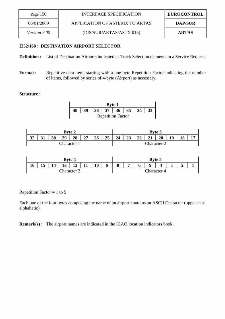
Page 150 INTERFACE SPECIFICATION EUROCONTROL
06/01/2009 APPLICATION OF ASTERIX TO ARTAS DAP/SUR
Version 7.00 (DIS/SUR/ARTAS/ASTX.015) ARTAS
I252/160 : DESTINATION AIRPORT SELECTOR Definition : List of Destination Airports indicated as Track Selection elements in a Service Request. Format : Repetitive data item, starting with a one-byte Repetition Factor indicating the number
of items, followed by series of 4-byte (Airport) as necessary. Structure :
Byte 1 40 39 38 37 36 35 34 33
Repetition Factor
Byte 2 Byte 3 32 31 30 29 28 27 26 25 24 23 22 21 20 19 18 17
Character 1 Character 2
Byte 4 Byte 5 16 15 14 13 12 11 10 9 8 7 6 5 4 3 2 1
Character 3 Character 4 Repetition Factor = 1 to 5 Each one of the four bytes composing the name of an airport contains an ASCII Character (upper-case alphabetic). Remark(s) : The airport names are indicated in the ICAO location indicators book.

EUROCONTROL INTERFACE SPECIFICATION Page 151
DAP/SUR APPLICATION OF ASTERIX TO ARTAS 06/01/2009
ARTAS (DIS/SUR/ARTAS.ASTX.015) Version 7.00
I252/170 : AIRCRAFT TYPE SELECTOR Definition : List of Aircraft Types indicated as Track Selection elements in a Service Request. Format : Repetitive data item, starting with a one-byte Repetition Factor indicating the number
of items, followed by series of 4-byte (Aircraft Type) as necessary. Structure :
Byte 1 40 39 38 37 36 35 34 33
Repetition Factor
Byte 2 Byte 3 32 31 30 29 28 27 26 25 24 23 22 21 20 19 18 17
Character 1 Character 2
Byte 4 Byte 5 16 15 14 13 12 11 10 9 8 7 6 5 4 3 2 1
Character 3 Character 4 Each one of the four bytes composing the type of aircraft contains an ASCII Character (upper-case alphanumeric characters with trailing spaces). Repetition Factor = 1 to 5 Remark(s) : The types of aircraft are defined in ICAO Document 4444.

Page 152 INTERFACE SPECIFICATION EUROCONTROL
06/01/2009 APPLICATION OF ASTERIX TO ARTAS DAP/SUR
Version 7.00 (DIS/SUR/ARTAS/ASTX.015) ARTAS
I252/190 : CURRENT CONTROL POSITION SELECTOR Definition : Identification of the Current Control Position to be used as track selector element in a
Service Request. Format : Two-bytes fixed length data item. Structure :
Byte 1 Byte 2 16 15 14 13 12 11 10 9 8 7 6 5 4 3 2 1
CENTRE POSITION bits 16/9 (CENTRE) 8-bit group identification code (0 to 255) bits 8/1 (POSITION) 8-bit Control Position identification code (0 to 255) Remark(s) : The centre and the control position identification codes have to be defined between
communication partners.

EUROCONTROL INTERFACE SPECIFICATION Page 153
DAP/SUR APPLICATION OF ASTERIX TO ARTAS 06/01/2009
ARTAS (DIS/SUR/ARTAS.ASTX.015) Version 7.00
I252/200 : TRACK/FLIGHT CATEGORIES SELECTOR Definition : This item defines which categories of tracks and/or flights shall be served. Format : fixed length four-byte data item. Structure :
Byte 1 Byte 2 32 31 30 29 28 27 26 25 24 23 22 21 20 19 18 17
TYP DETECT VALTI STCOR TNT SPI ME TRAF
Byte 3 Byte 4 16 15 14 13 12 11 10 9 8 7 6 5 4 3 2 1
FCAT NVD NUA NES SBL spare this item defines a number of track/flight selection categories which will be combined as follows : ((TYP and DETECT and VALTI and STCOR and TNT and ADS_B) or SPI or ME) and (TRAF or FCAT) Where ADS_B = NVD and NUA and NES bits 32/31 (TYP) 0 tracks from live surveillance reports 1 tracks from simulated surveillance reports 2 tracks from both live and simulated surveillance
reports bits 30/26 (DETECT) is used to filter out tracks depending on which type of surveillance report(s)
have been recently processed for the track. bit 30 0 No filtering applied 1 Tracks built from combined radar reports or both primary
and secondary radar reports shall not be served. bit 29 0 No filtering applied 1 Tracks built only from SSR radar reports shall not be served. bit 28 0 No filtering applied 1 Tracks built only from PSR radar reports shall not be served. bit 27 0 Not used. bit 26 0 No filtering applied 1 Tracks built from ADS-B target reports shall not be served bits 25/24 (VALTI) 0 Default. All tracks are selected.

Page 154 INTERFACE SPECIFICATION EUROCONTROL
06/01/2009 APPLICATION OF ASTERIX TO ARTAS DAP/SUR
Version 7.00 (DIS/SUR/ARTAS/ASTX.015) ARTAS
1 All tracks that have a calculated track barometric altitude (I062/135) or a measured flight level (I062/136) are selected.
2 All tracks having a calculated track geometric altitude (I062/130) computed using assumed height are selected.
bits 23/22 (STCOR) 0 default 1 tracks correlated to Flight Plan(s) only 2 tracks not correlated to Flight Plan(s) only bit 21 (TNT) 0 tentative tracks shall be sent 1 tentative tracks shall not be sent bit 20 (SPI) 0 tracks with SPI flag shall be sent 1 tracks with SPI flag shall not be sent bit 19 (ME) 0 tracks with ME flag shall be sent 1 tracks with ME flag shall not be sent bits 18/17 (TRAF) 0 all traffic 1 General Air Traffic, 2 Operational Air Traffic bit 16/14 (FCAT) is used to indicate which flight category(ies) shall be selected. bit 16 0 IFR selected bit 15 0 VFR selected bit 14 0 CVFR selected bit 13 (NVD) 0 No filtering applied. 1 No VDL 4 tracks i.e. Tracks built from VDL4 ADS-B
target reports shall not be served bit 12 (NUA) 0 No filtering applied. 1 No UAT tracks i.e Tracks built from UAT ADS-B
target reports shall not be served bit 11 (NES) 0 No filtering applied. 1 No Extended Squitter tracks i.e. Tracks built from ES
ADS-B target reports shall not be served bit 10 (SBL) 0 No filtering applied.

EUROCONTROL INTERFACE SPECIFICATION Page 155
DAP/SUR APPLICATION OF ASTERIX TO ARTAS 06/01/2009
ARTAS (DIS/SUR/ARTAS.ASTX.015) Version 7.00
1 Send Blunders. This track selector is used in
conjunction with the NVD, NUA, and NES track selectors to indicate whether tracks for which a blunder has been detected should not be filtered out as a result of the NVD, NUA, NES track selectors.
bit 9/1 (spare) spare bits set to 0 Remark(s) : • The combined only tracks that are filtered out (bit 30 = 1) shall be those tracks with an PSR age
less than a parameter time, and with SSR age less than a parameter time and with all the ADS-B ages (ADS-B VDL4 age, ADS-B UAT age, and ADS-B Extended Squitter age) greater than a parameter time.
• The SSR tracks that are filtered out (bit 29 = 1) shall be those tracks with SSR age less than a parameter time and PSR age greater than a parameter time and all the ADS-B ages greater than a parameter time.
• The primary tracks (that are filtered out bit 28 = 1) shall be those tracks with an PSR age less than a parameter time and an SSR age greater than a parameter time and with all the ADS-B ages (ADS-B VDL4 age, ADS-B UAT age, and ADS-B Extended Squitter age) greater than a parameter time.
• bit 27 shall be set to 0. It is reserved for possible future use, for example for selecting Mode S only tracks.
• The ADS-B tracks that are filtered out (bit 26=1) shall be those tracks with an ADS-B VDL4 age, an ADS-B UAT age, or an ADS-B Extended Squitter age less than a parameter time.
• The VDL4 ADS-B tracks that are filtered out (bit 13=1) shall be those tracks with an ADS-B VDL4 age less than a parameter time. If however the SBL flag is set (i.e. bit 10 =1) tracks with an an ADS-B VDL4 age less than a parameter time that have received a poor ADS-B target report (called a blunder) shall also be served.
• The UAT ADS-B tracks that are filtered out (bit 12=1) shall be those tracks with an ADS-B UAT age less than a parameter time. If however the SBL flag is set (i.e. bit 10 =1) tracks with an ADS-B UAT age less than a parameter time that have received a poor ADS-B target report (called a blunder) shall also be served.
• The ES ADS-B tracks that are filtered out (bit 11=1) shall be those tracks with an ADS-B ES age less than a parameter time. If however the SBL flag is set (i.e. bit 10 =1) tracks with an ADS-B ES age less than a parameter time that have received a poor ADS-B target report (called a blunder) shall also be served.

Page 156 INTERFACE SPECIFICATION EUROCONTROL
06/01/2009 APPLICATION OF ASTERIX TO ARTAS DAP/SUR
Version 7.00 (DIS/SUR/ARTAS/ASTX.015) ARTAS
I252/210 : ITEM SELECTOR Definition : The Item Selector is used to define the composition of the track information messages.
The bits that compose the Item Selector identify the data items, and in some cases the subfields of data items that are to be included in each track update.
Format : Variable length data item comprising a first part of two bytes, followed by 2-byte
extents as necessary. Structure : Each bit set to 1 means that the corresponding item is selected and has to be transmitted.
Byte 1 Byte 2 144 143 142 141 140 139 138 137 136 135 134 133 132 131 130 129 DSI SI TN TM3 TTI TS CTP CTW TM5 TM2 CGA CBA MFL CTC MM FX
bit 144 (DSI) Data Source Identifier (I062/010)
bit 143 (SI) Service Identification (I062/015)
bit 142 (TN) Track Number (I062/040)
bit 141 (TM3) Track Mode 3/A Code (I062/060)
bit 140 (TTI) Time Of Track Information (I062/070)
bit 139 (TS) Track Status (I062/080)
bit 138 (CTP) Calculated Track Position (Cartesian) (I062/100)
bit 137 (CTW) Calculated Track Position WGS 84 (I062/105)
bit 136 (TM5) Mode 5 Data Reports & Extended Mode 1 Code (I062/110)
bit 135 (TM2) Track Mode 2 Code (I062/120)
bit 134 (CGA) Calculated Track Geometric Altitude (I062/130)
bit 133 (CBA) Calculated Track Barometric Altitude (I062/135)
bit 132 (MFL) Measured Flight Level (I062/136)
bit 131 (CTC) Calculated Track Velocity (Cartesian) (I062/185)
bit 130 (MM) Mode Of Movement (I062/200)
bit 129 (FX) Field Extension

EUROCONTROL INTERFACE SPECIFICATION Page 157
DAP/SUR APPLICATION OF ASTERIX TO ARTAS 06/01/2009
ARTAS (DIS/SUR/ARTAS.ASTX.015) Version 7.00
Byte 3 Byte 4
128 127 126 125 124 123 122 121 120 119 118 117 116 115 114 113 CAC CRC TI TSO TA PSR SSR MDS ADS ES VDL UAT LOP MLT MFL FX
bit 128 (CAC) Calculated Acceleration (Cartesian) (I062/210)
bit 127 (CRC) Calculated Rate Of Climb/Descent (I062/220)
bit 126 (TI) Target Identification (I062/245)
bit 125 (TSO) Target Size & Orientation (I062/270)
bit 124 (TA) Track Age (I062/290 sf1)
bit 123 (PSR) PSR Age (I062/290 sf2)
bit 122 (SSR) SSR Age (I062/290 sf3)
bit 121 (MDS) Mode S Age (I062/290 sf4)
bit 120 (ADS) ADS-C Age (I062/290 sf5)
bit 119 (ES) ADS-B Extended Squitter Age (I062/290 sf6)
bit 118 (VDL) ADS-B VDL Mode 4 Age (I062/290 sf7)
bit 117 (UAT) ADS-B UAT Age (I062/290 sf8)
bit 116 (LOP) Loop Age (I062/290 sf9)
bit 115 (MLT) Multilateration Age (I062/290 sf10)
bit 114 (MFL) Measured Flight Level Age (I062/295 sf1)
bit 113 (FX) Field Extension
Byte 5 Byte 6
112 111 110 109 108 107 106 105 104 103 102 101 100 99 98 97 MD1 MD2 MDA MD4 MD5 MHA IAA TSA SAA FSA TIA COA SBA ACA BVA FX
bit 112 (MD1) Mode 1 Age (I062/295 sf2)
bit 111 (MD2) Mode 2 Age (I062/295 sf3)
bit 110 (MDA) Mode 3/A Age (I062/295 sf4)
bit 109 (MD4) Mode 4 Age (I062/295 sf5)
bit 108 (MD5) Mode 5 Age (I062/295 sf6)
bit 107 (MHA) Magnetic Heading Age (I062/295 sf7)
bit 106 (IAA) Indicated Airspeed/Mach No Age (I062/295 sf8)
bit 105 (TSA) True Airspeed Age (I062/295 sf9)
bit 104 (SAA) Selected Altitude Age (I062/295 sf10)
bit 103 (FSA) Final Selected Altitude Age (I062/295 sf11)
bit 102 (TIA) Trajectory Intent Age (I062/295 sf12)
bit 101 (COA) Communications / ACAS Capability and Flight Status Age (I062/295 sf13)
bit 100 (SBA) Status Reported by ADS-B Age (I062/295 sf14)

Page 158 INTERFACE SPECIFICATION EUROCONTROL
06/01/2009 APPLICATION OF ASTERIX TO ARTAS DAP/SUR
Version 7.00 (DIS/SUR/ARTAS/ASTX.015) ARTAS
bit 99 (ACA) ACAS Resolution Advisory Report Age (I062/295 sf15)
bit 98 (BVA) Barometric Vertical Rate Age (I062/295 sf16)
bit 97 (FX) Field Extension
Byte 7 Byte 8
96 95 94 93 92 91 90 89 88 87 86 85 84 83 82 81 GVA RAA TRA TAA GSA VUA MEA EMA PBA GAA PUA MBA IAR MAC MCP FX
bit 96 (GVA) Geometric Vertical Rate Age (I062/295 sf17)
bit 95 (RAA) Roll Angle Age (I062/295 sf18)
bit 94 (TRA) Track Angle Rate Age (I062/295 sf19)
bit 93 (TAA) Track Angle Age (I062/295 sf20)
bit 92 (GSA) Ground Speed Age (I062/295 sf21)
bit 91 (VUA) Velocity Uncertainty Age (I062/295 sf22)
bit 90 (MEA) Meteorological Data Age (I062/295 sf23)
bit 89 (EMA) Emitter Category Age (I062/295 sf24)
bit 88 (PBA) Position Data Age (I062/295 sf25)
bit 87 (GAA) Geometric Altitude Data Age (I062/295 sf26)
bit 86 (PUA) Position Uncertainty Data Age (I062/295 sf27)
bit 85 (MBA) Mode S MB Data Age (I062/295 sf28)
bit 84 (IAR) Indicated Airspeed Data Age (I062/295 sf29)
bit 83 (MAC) Mach Number Data Age (I062/295 sf30)
bit 82 (MCP) MCP/FCU Selected Altitude Data Age (I062/295 sf31)
bit 81 (FX) Field Extension
Byte 9 Byte 10
80 79 78 77 76 75 74 73 72 71 70 69 68 67 66 65 FMS BPS TAL MFM VFI MI BDS BDA TA TI MHG TAS SAL FSS TIS FX
bit 80 (FMS) FMS Selected Altitude Data Age (I062/295 sf32)
bit 79 (BPS) Barometric Pressure Setting Data Age (I062/295 sf33)
bit 78 (TAL) Target Altitude Source Data Age (I062/295 sf34)
bit 77 (MFM) MCP/FCU Mode Data Age (I062/295 sf35)
bit 76 (VFI) Vehicle Fleet Identification (I062/300)
bit 75 (MI) Measured Information (I062/340)
bit 74 (BDS) Mode S BDS Registers (I062/350)
bit 73 (BDA) Mode S BDS Register Ages (I062/360)

EUROCONTROL INTERFACE SPECIFICATION Page 159
DAP/SUR APPLICATION OF ASTERIX TO ARTAS 06/01/2009
ARTAS (DIS/SUR/ARTAS.ASTX.015) Version 7.00
bit 72 (TA) Target Address (I062/380 sf1)
bit 71 (TI) Target Identification (I062/380 sf2)
bit 70 (MHG) Magnetic Heading (I062/380 sf3)
bit 69 (TAS) True Airspeed (I062/380 sf5)
bit 68 (SAL) Selected Altitude (I062/380 sf6)
bit 67 (FSS) Final State Selected Altitude (I062/380 sf7)
bit 66 (TIS) Trajectory Intent Status (I062/380 sf8)
bit 65 (FX) Field Extension
Byte 11 Byte 12
64 63 62 61 60 59 58 57 56 55 54 53 52 51 50 49 TID COM SAB ACS BVR GVR RAN TAR TAN GSP VUN MET EMC PD GAD FX
bit 64 (TID) Trajectory Intent Data (I062/380 sf9)
bit 63 (COM) Communications / ACAS Capability and Flight Status (I062/380 sf10)
bit 62 (SAB) Status reported by ADS-B (I062/380 sf11)
bit 61 (ACS) ACAS Resolution Advisory Report (I062/380 sf12)
bit 60 (BVR) Barometric Vertical Rate (I062/380 sf13)
bit 59 (GVR) Geometric Vertical Rate (I062/380 sf14)
bit 58 (RAN) Roll Angle (I062/380 sf15)
bit 57 (TAR) Track Angle Rate (I062/380 sf16)
bit 56 (TAN) Track Angle (I062/380 sf17)
bit 55 (GSP) Ground Speed (I062/380 sf18)
bit 54 (VUN) Velocity Uncertainty (I062/380 sf19)
bit 53 (MET) Meteorological Data (I062/380 sf20)
bit 52 (EMC) Emitter Category (I062/380 sf21)
bit 51 (PD) Position Data (I062/380 sf22)
bit 50 (GAD) Geometric Altitude Data (I062/380 sf23)
bit 49 (FX) Field Extension
Byte 13 Byte 14
48 47 46 45 44 43 42 41 40 39 38 37 36 35 34 33 PUD MB IAR MAC MCU FMS BPS TAL MFM TAG CSN IFI FCT TAC WTC FX
bit 48 (PUD) Position Uncertainty Data (I062/380 sf24)
bit 47 (MB) Mode S MB Data (I062/380 sf25)
bit 46 (IAR) Indicated Airspeed (I062/380 sf26)

Page 160 INTERFACE SPECIFICATION EUROCONTROL
06/01/2009 APPLICATION OF ASTERIX TO ARTAS DAP/SUR
Version 7.00 (DIS/SUR/ARTAS/ASTX.015) ARTAS
bit 45 (MAC) Mach Number (I062/380 sf27)
bit 44 (MCU) MCP/FCU Selected Altitude (I062/380 sf28)
bit 43 (FMS) FMS Selected Altitude (I062/380 sf29)
bit 42 (BPS) Barometric Pressure Setting (I062/380 sf30)
bit 41 (TAL) Target Altitude Source (I062/380 sf31)
bit 40 (MFM) MCP/FCU Mode (I062/380 sf32)
bit 39 (TAG) FPPS Identification Tag (I062/390 sf1)
bit-38 (CSN) Callsign (I062/390 sf2)
bit-37 (IFI) IFPS_FLIGHT_ID (I062/390 sf3)
bit-36 (FCT) Flight Category (I062/390 sf4)
bit-35 (TAC) Type of Aircraft (I062/390 sf5)
bit-34 (WTC) Wake Turbulence Category (I062/390 sf6)
bit-33 (FX) Field Extension
Byte 15 Byte 16
32 31 30 29 28 27 26 25 24 23 22 21 20 19 18 17 DEP DST RDS CFL CTL TOD AST STS STD STA APC XYC APW AGA ABA FX
bit-32 (DEP) Departure Airport (I062/390 sf7)
bit-31 (DST) Destination Airport (I062/390 sf8)
bit-30 (RDS) Runway Designation (I062/390 sf9)
bit-29 (CFL) Current Cleared Flight Level (I062/390 sf10)
bit-28 (CTL) Current Control Position (I062/390 sf11)
bit-27 (TOD) Time of Departure / Arrival (I062/390 sf12)
bit-26 (AST) Aircraft Stand (I062/390 sf13)
bit-25 (STS) Stand Status (I062/390 sf14)
bit-24 (STD) Standard Instrument Departure (I062/390 sf15)
bit-23 (STA) STandard Instrument Arrival (I062/390 sf16)
bit 22 (APC) Estimated Accuracy Of Track Position (Cartesian) (I062/500 sf1)
bit 21 (XYC) XY Covariance (I062/500 sf2)
bit 20 (APW) Estimated Accuracy Of Track Position (WGS-84) (I062/500 sf3)
bit 19 (AGA) Estimated Accuracy Of Calculated Track Geometric Altitude (I062/500 sf4)
bit 18 (ABA) Estimated Accuracy Of Calculated Track Barometric Altitude (I062/500sf5)
bit 17 (FX) Field Extension
Byte 17 Byte 18

EUROCONTROL INTERFACE SPECIFICATION Page 161
DAP/SUR APPLICATION OF ASTERIX TO ARTAS 06/01/2009
ARTAS (DIS/SUR/ARTAS.ASTX.015) Version 7.00
16 15 14 13 12 11 10 9 8 7 6 5 4 3 2 1
ATV AA ARC CTN RE SP spare FX
bit 16 (ATV) Estimated Accuracy Of Track Velocity (Cartesian) (I062/500 sf6)
bit 15 (AA) Estimated Accuracy Of Acceleration (Cartesian) (I062/500 sf7)
bit 14 (ARC) Estimated Accuracy Of Rate Of Climb/Descent (I062/500 sf8)
bit 13 (CTN) Composed Track Number (I062/510)
bit 12 (RE) Reserved Expansion Field (I062/RE)
bit 11 (SP) Special Purpose Field (I062/SP)
bits 10/2 (spare) Spare bits set to zero.
bit 1 (FX) Field Extension Remark(s) :

Page 162 INTERFACE SPECIFICATION EUROCONTROL
06/01/2009 APPLICATION OF ASTERIX TO ARTAS DAP/SUR
Version 7.00 (DIS/SUR/ARTAS/ASTX.015) ARTAS
I252/220 : CYCLICAL UPDATE CHARACTERISTICS Definition : Definition of the Scanning Period, Update Period, Max Data Flow and Extra Delay (to
be considered for the track extrapolation) in case of cyclical service. Format : Five-byte fixed length data item. Structure :
Byte 1 40 39 38 37 36 35 34 33 sb MSD SCANNING PERIOD
Byte 2 Byte 3 32 31 30 29 28 27 26 25 24 23 22 21 20 19 18 17 BATCH PERIOD UPDATE PERIOD
Byte 4 Byte 5 16 15 14 13 12 11 10 9 8 7 6 5 4 3 2 1
sb EXTRA DELAY sb MAXFLOW bit 40 spare bit set to 0 bit 39 Directive for scanning the mosaic (from south-west corner to north-east corner) : (MSD) = 0 scanning by column 1 scanning by row bits 38/33 (SCANNING PERIOD) i.e. time for scanning the mosaic : range : from 6 to 32 batch periods, and 3 sec <= SCANNING PERIOD <= 16 sec bits 32/29 (BATCH PERIOD) i.e. time period between two consecutive batches : range : from 1 to 15 steps of 100 ms, bits 28/17 (UPDATE PERIOD) i.e. time period between the same batch of two consecutive scans : range : from 6 to 3000 batch periods, and SCANNING PERIOD <= UPDATE PERIOD <= 5 minutes bits 16/15 spare bits set to 0
[CONT’D]

EUROCONTROL INTERFACE SPECIFICATION Page 163
DAP/SUR APPLICATION OF ASTERIX TO ARTAS 06/01/2009
ARTAS (DIS/SUR/ARTAS.ASTX.015) Version 7.00
bits 14/9 (DELAY) : range : 0 to 35 steps of 100 ms (i.e. 0 <= DELAY <= 3.5 seconds) bit 8 spare bit set to 0 bits 7/1 (MAXFLOW) i.e. Maximum User input Data Flow : range : 1 to 127 Kbytes/second Remark(s) :

Page 164 INTERFACE SPECIFICATION EUROCONTROL
06/01/2009 APPLICATION OF ASTERIX TO ARTAS DAP/SUR
Version 7.00 (DIS/SUR/ARTAS/ASTX.015) ARTAS
I252/230 : RADAR SYNCHRONISATION CHARACTERISTICS Definition : Transmission Characteristics for a service of the type radar synchronised. Format : Variable length data item comprising a first part of three bytes, followed by three bytes
as necessary. Structure :
Byte 1 Byte 2 48 47 46 45 44 43 42 41 40 39 38 37 36 35 34 33
MSAC MSIC
Byte 3 32 31 30 29 28 27 26 25
NOP sb FX
Byte 4 Byte 5 24 23 22 21 20 19 18 17 16 15 14 13 12 11 10 9
BSAC BSIC
Byte 6 8 7 6 5 4 3 2 1
sb FX Main Radar Identification Tag : bits 48/41 (MSAC) Source Area Code (0 → 255) bits 40/33 (MSIC) Source Identity Code (0 → 255) bit 32 (NOP) : directive with respect to tracks falling in the radar range but which are not
updated by plots from the reference radar : 0 no information shall be sent, 1 a track update shall be sent after the time-window for the plot-to-track
association is passed without a plot has been associated. bits 31/26 spare bits set to 0 bit 25 (FX) Field Extension Backup Radar Identification Tag : bits 24/17 (BSAC) Source Area Code (0 → 255) bits 16/9 (BSIC) Source Identity Code (0 → 255) bits 8/2 spare bits set to 0 bit 1 (FX) Field Extension Remark(s) : SACs have been defined worldwide and can be accessed on the EUROCONTROL
ASTERIX website (www.eurocontrol.int/asterix)..

EUROCONTROL INTERFACE SPECIFICATION Page 165
DAP/SUR APPLICATION OF ASTERIX TO ARTAS 06/01/2009
ARTAS (DIS/SUR/ARTAS.ASTX.015) Version 7.00
I252/240 : DISCRETE PARAMETERS FLAGS Definition : This item contains a number of flags to indicate which category(ies) of discrete
events shall be considered for triggering the track information transmission (a-periodical way of transmission).
Format : Two-byte variable length data item. Structure :
Byte 1 Byte 2 16 15 14 13 12 11 10 9 8 7
6 5 4 3 2 1
TLF TNB TQY PLN M3A MO2 COR SPE MOF ETU sb FX Set of selection flags meaning that, when set to 1, a track information update shall be sent at each occurrence of the discrete event. bit 16 (TLF) Track Life events (Birth, Death, no radar update) bit 15 (TNB) ARTAS Track Number changes (switch Master/Slave Track
Number), bit 14 (TQY) Modifications of Track Quality, bit 13 (PLN) Modification of Flight Plan related information (i.e. in the
Miniplan), bit 12 (M3A) Change of Mode 3/A identity bit 11 (MO2) Change of Mode 2 identification bit 10 (COR) Flight-plan to Track correlation/end of correlation bit 9 (SPE) Special Mode 3/A transponding (7500, 7600 and 7700), bit 8 (MOF) Change of Mode-of-Flight. bit 7 (ETU) Each Track Update bits 6/2 spare bits set to 0 bit 1 FX Extension field Remark(s) :

Page 166 INTERFACE SPECIFICATION EUROCONTROL
06/01/2009 APPLICATION OF ASTERIX TO ARTAS DAP/SUR
Version 7.00 (DIS/SUR/ARTAS/ASTX.015) ARTAS
I252/250 : MOF PROBABILITY CRITERION Definition : Variation step of Mode-of-Flight Probabilities to trigger the transmission of track
information updates (i.e. an update will be sent each time the variation between the current and the last transmitted MOF probability assessment for a given track exceeds the indicated threshold value).
Format : One-byte fixed length data item. Structure :
Byte 1 8 7 6 5 4 3 2 1
LSB The MOF Probability Criterion is expressed in percentage (%) : bit 1 (LSB) = (2E-2)% = 0.25% Maximum value : 64% Remark(s) :

EUROCONTROL INTERFACE SPECIFICATION Page 167
DAP/SUR APPLICATION OF ASTERIX TO ARTAS 06/01/2009
ARTAS (DIS/SUR/ARTAS.ASTX.015) Version 7.00
I252/255 : RATE OF CLIMB/DESCENT CRITERION Definition : Variation step of the calculated rate of climb/descent to trigger the transmission of
track information updates (i.e. an update will be sent each time the variation between the current and the last transmitted assessment of the rate of climb/ descent for a given track exceeds the indicated threshold value).
Format : Two-bytes fixed length data item. Structure :
Byte 1 Byte 2 16 15 14 13 12 11 10 9 8 7 6 5 4 3 2 1
RATE OF C/D LSB
bit 1 (LSB) (2E-10)FL/s = 5.86 feet/minute Remark(s) :

Page 168 INTERFACE SPECIFICATION EUROCONTROL
06/01/2009 APPLICATION OF ASTERIX TO ARTAS DAP/SUR
Version 7.00 (DIS/SUR/ARTAS/ASTX.015) ARTAS
I252/260 : POSITION CRITERION Definition : Variation step of Track positional information to trigger the transmission of track
updates. An update will be sent each time the variation between the current track position and the extrapolated position based on the previously sent information exceeds the indicated threshold.
Format : One-byte fixed length data item. Structure :
Byte 1 8 7 6 5 4 3 2 1
LSB The Position Criterion is expressed in Nautical Miles and applies on both X and Y coordinates. bit 1 (LSB) (2E-6)NM = 1/64 NM Maximum value = 4 NM Remark(s) :

EUROCONTROL INTERFACE SPECIFICATION Page 169
DAP/SUR APPLICATION OF ASTERIX TO ARTAS 06/01/2009
ARTAS (DIS/SUR/ARTAS.ASTX.015) Version 7.00
I252/265 : RATE OF TURN CRITERION Definition : Variation step of the calculated rate of turn to trigger the transmission of track
information updates (i.e. an update will be sent each time the variation between the current and the last transmitted assessment of the rate of turn for a given track exceeds the indicated threshold value).
Format : One-byte fixed length data item. Structure :
Byte 1 8 7 6 5 4 3 2 1
LSB bit 1 (LSB) (2E-2) °/s = 1/4 °/s Maximum value = 64 °/s Remark(s) :

Page 170 INTERFACE SPECIFICATION EUROCONTROL
06/01/2009 APPLICATION OF ASTERIX TO ARTAS DAP/SUR
Version 7.00 (DIS/SUR/ARTAS/ASTX.015) ARTAS
I252/270 : HEADING CRITERION Definition : Variation step of heading (i.e. Speed Vector) to trigger the transmission of track
information updates (i.e. an update will be sent each time the variation between the current and the last transmitted Track Heading assessment for a given track exceeds the indicated threshold value).
Format : One-byte fixed length data item. Structure :
Byte 1 8 7 6 5 4 3 2 1
LSB The Heading Criterion is expressed in degrees. bit 1 (LSB) 360°/(2E14) = 0.02197° Maximum value = 5.6° Remark(s) :

EUROCONTROL INTERFACE SPECIFICATION Page 171
DAP/SUR APPLICATION OF ASTERIX TO ARTAS 06/01/2009
ARTAS (DIS/SUR/ARTAS.ASTX.015) Version 7.00
I252/280 : SPEED MODULE CRITERION Definition : Variation step of Speed Module to trigger the transmission of track information
updates (i.e. an update will be sent each time the variation between the current and the last transmitted Speed Module assessment for a given track exceed the indicated threshold value).
Format : One-byte fixed length data item. Structure :
Byte 1 8 7 6 5 4 3 2 1
LSB The Speed Module Criterion is expressed in Knots. bit 1 (LSB) = 1 kt Maximum value = 255 kt Remark(s) :

Page 172 INTERFACE SPECIFICATION EUROCONTROL
06/01/2009 APPLICATION OF ASTERIX TO ARTAS DAP/SUR
Version 7.00 (DIS/SUR/ARTAS/ASTX.015) ARTAS
I252/290 : ALTITUDE CRITERION Definition : A threshold for triggering the transmission of a track. A track update will be sent each
time the calculated track altitude or calculated track flight level has changed by more than the indicated amount since the last track update.
Format : One-byte fixed length data item. Structure :
Byte 1 8 7 6 5 4 3 2 1
LSB bit 1 (LSB) = 1/4 FL (25 feet) Maximum value = FL 32 Remark(s) :

EUROCONTROL INTERFACE SPECIFICATION Page 173
DAP/SUR APPLICATION OF ASTERIX TO ARTAS 06/01/2009
ARTAS (DIS/SUR/ARTAS.ASTX.015) Version 7.00
I252/300 : FACTOR K Definition : The so-called factor K is used to trigger the data transmission as a function of the
internal accuracy by which the ARTAS Tracker has estimated the state vector elements. An update will be sent each time one of the state vector elements has varied from more than K time the standard deviation associated to this element.
Format : One-byte fixed length data item. Structure :
Byte 1 8 7 6 5 4 3 2 1
LSB bit 1 (LSB) = (2E-3) = 1/8 Maximum value ≅ 32 Remark(s) :

Page 174 INTERFACE SPECIFICATION EUROCONTROL
06/01/2009 APPLICATION OF ASTERIX TO ARTAS DAP/SUR
Version 7.00 (DIS/SUR/ARTAS/ASTX.015) ARTAS
I252/310 : REFRESHMENT PERIOD Definition : In relation to a service applying the a-periodical mode of transmission, the Refreshment
Period concerns the systematic transmission of track updates for those tracks for which no changes have been detected.
Format : One-byte fixed length data item. Structure :
Byte 1 8 7 6 5 4 3 2 1
LSB bit 1 (LSB) = 1 second
Maximum value = 255 seconds (4 mn 15 s) Remark(s) :

EUROCONTROL INTERFACE SPECIFICATION Page 175
DAP/SUR APPLICATION OF ASTERIX TO ARTAS 06/01/2009
ARTAS (DIS/SUR/ARTAS.ASTX.015) Version 7.00
I252/320 : MINIMAL PERIOD Definition : In relation to a service applying the a-periodical mode of transmission, a Minimal
Period shall be specified to avoid that too close transmission intervals are applied when highly manoeuvring aircraft are tracked.
Format : One-byte fixed length data item. Structure :
Byte 1 8 7 6 5 4 3 2 1
LSB bit 1 (LSB) = 1 second Maximum value = 255 seconds (4 mn 15 s) Remark(s) :

Page 176 INTERFACE SPECIFICATION EUROCONTROL
06/01/2009 APPLICATION OF ASTERIX TO ARTAS DAP/SUR
Version 7.00 (DIS/SUR/ARTAS/ASTX.015) ARTAS
I252/330 : SERVICE RELATED REPORT Definition : Report message sent by the Server to the User in relation to a connection or a service. Format : Repetitive data item, starting with a one-byte Repetition Factor indicating the number
of items, followed by series of 2-byte (Acknowledgement message) as necessary. Structure :
Byte 1 24 23 22 21 20 19 18 17
Repetition factor
Byte 2 Byte 3 16 15 14 13 12 11 10 9 8 7 6 5 4 3 2 1
NATURE CODE Byte 1 Repetition Factor : 1 to 255 (The Repetition Factor may be > 1 when several errors have
been detected within the same Service Request). extent(s) Report Message : bits 16/12 (NATURE) of the message to which the Report refers (0 to 31). (NATURE) = 0 : Server status message 1 : Service initial request report 2 : Service update request report : stop track/item transmission 3 : Service update request report : start track/item transmission 4 : Service control request report : interruption 5 : Service control request report : restart 6 : Service control request report : end of service 7 : Error in default service 8 : Service synchronisation report (periodical or radar synchronised service)
[CONT’D]

EUROCONTROL INTERFACE SPECIFICATION Page 177
DAP/SUR APPLICATION OF ASTERIX TO ARTAS 06/01/2009
ARTAS (DIS/SUR/ARTAS.ASTX.015) Version 7.00
bits 11/1 Report (CODE) :
For NATURE = 0 to 7, CODE contains a report code, as listed below, For NATURE = 8, CODE contains a batch or a sector number related to the execution of a service : 0 to N-1, N being either the number of batches or the number of sectors managed internally by ARTAS (16 or 32)
The following CODEs may be sent by ARTAS in case of a nature from 0 to 7. 1 = service degradation, 2 = service degradation ended, 3 = main radar out of service, 4 = service interrupted by the ARTAS operator, 5 = service interrupted due to contingency, 6 = ready for service restart after contingency, 7 = Request accepted, 8 = Server unable to accept the request (overload conditions), 9 = Service refused, the maximum number of simultaneous services per User being already
reached for that User, 10 = Service Identification already existing, 11 = Incorrect Service Identification, 12 = Incorrect point(s) definition of in the geographical sub-area, 13 = Incorrect definition of Upper/Lower Limit(s) in the geographical sub-area, 14 = crossing lines in the geographical sub-area, 15 = point(s) defined outside the User Domain of Interest, 16 = number of points below the minimum value, 17 = number of points exceeding the maximum, 18 = Repetition Factor of Callsign Selector exceeding the maximum value, 19 = Incorrectly coded Callsign(s), 20 = Repetition Factor of Track Number Selector exceeding the maximum value, 21 = Incorrect Track Number(s), 22 = Repetition Factor of Aircraft Address Selector exceeding the maximum value, 23 = Repetition Factor of Aircraft Identification Selector exceeding the maximum value, 24 = Incorrect Aircraft Identification(s), 25 = Repetition Factor of Code Family Selector exceeding the maximum value, 26 = Repetition Factor of the Departure Airport Selector exceeding the maximum value, 27 = Incorrectly coded Departure Airport(s), 28 = Repetition Factor of the Destination Airport Selector exceeding the maximum value 29 = Incorrectly coded Destination Airport(s), 30 = Repetition Factor of Aircraft Type Selector exceeding the maximum value, 31 = Incorrectly coded Aircraft Type(s), 32 = Incorrectly coded Current Control Position, 33 = Wrong track/flight categories selector 34 = Mixed definition of periodical/a-periodical transmission characteristics, 35 = Update period below the minimum value, 36 = Update period over the maximum value, 37 = scanning period below the minimum value,

Page 178 INTERFACE SPECIFICATION EUROCONTROL
06/01/2009 APPLICATION OF ASTERIX TO ARTAS DAP/SUR
Version 7.00 (DIS/SUR/ARTAS/ASTX.015) ARTAS
38 = scanning period over the maximum value, 39 = Extra delay over the maximum value 40 = Max flow below the minimum value 41 = Max flow over the maximum value 42 = Unknown Main Radar Station, 43 = Background service not identified, 44 = More than one Background service have been identified. 45 = syntax error in the request (e.g. missing items). 46 = maximum number of simultaneous radar synchronised service is reached. 47 = Main radar outside the maximum user domain of interest, 48 = non existing referenced service, 49 = mixed definition of geographical and non-geographical track selection keys, 50 = number of exclusion areas exceeding the maximum, 51 = number of layers for an exclusion area exceeding the maximum, 52 = defined geographical area already excluded, 53 = Too many sub-domains, 54 = Too many sub-domain layers, 55 = Service already interrupted, 56 = Service already active. 57 = NO LONGER USED BY ARTAS 58 = Service ended by the operator 59 = failure of user main radar 60 = Incorrectly coded Discrete Parameters Flags 61 = Incorrectly coded Item Selector 62 = Mixed definition of item and track selection keys 63 = Incorrect definition of the Upper/Lower limits in the update geographical area 64 = Crossing lines in the definition of the update geographical area, 65 = Service update no longer possible, 66 = No initial service, 67 = Not possible to restart complementary service while background is interrupted, 68 = Complementary service not defined, 69 = Illegal background state, 70 = Illegal background type, 71 = Illegal connection number, 72 = Illegal service type, 73 = User not connected, 74 = Service restarted by the ARTAS Operator, 75 = Refresh period less or equal than minimal period, 76 = Batch period below the minimum value, 77 = Update period less than scanning period, 78 = Main radar becoming operational, 79 = Main radar becoming degraded, 80 = Service continuity interrupted due to disconnection with adjacent Unit, 81 = Service continuity restarted, 82 = Radar synchronised subarea going beyond the ARTAS Unit DoI, 83 = Service synchronised on backup radar, 84 = Service synchronised on main radar, 85 = Main and backup radars, if any, failed, 86 = Unknown backup radar.

EUROCONTROL INTERFACE SPECIFICATION Page 179
DAP/SUR APPLICATION OF ASTERIX TO ARTAS 06/01/2009
ARTAS (DIS/SUR/ARTAS.ASTX.015) Version 7.00
87 = Incorrectly coded radar synchronisation characteristics 88 = Unknown Sensor(s) 89 = Refresh period out of bounds 90 = Time Stamping Bias change threshold out of bounds 91 = SSR Range Bias change threshold out of bounds 92 = SSR Range gain change threshold out of bounds 93 = PR Range Bias change threshold out of bounds 94 = PR Range gain change threshold out of bounds 95 = Repetition Factor of Sensor Selector exceeding the maximum value 96 = Sensor Service Not Defined Remark(s) : The following reports are only sent to category 30 broadcast users: nature 0 or 8, codes 1,2,3,4,5,6,58,59,74,78,79,80,81,83,84, or 85.

Page 180 INTERFACE SPECIFICATION EUROCONTROL
06/01/2009 APPLICATION OF ASTERIX TO ARTAS DAP/SUR
Version 7.00 (DIS/SUR/ARTAS/ASTX.015) ARTAS
I252/340 : SCALING FACTOR Definition : This item is used to select the precision by which will be coded a cartesian track
position. Format : One-byte fixed length data item. Structure :
Byte 1 8 7 6 5 4 3 2 1
SF sb bit 8 (SF) = 0 Track Position coding precision = 1/64 NM, 1 Track Position coding precision = 1/32 NM. bits 7/1 (sb) spare bits set to 0 Remark(s) : A scaling factor of 1/32 NM is required for any User defining a Domain of Interest
extending beyond a square of 1024 NM X 1024 NM centred on the Unit Centre Point of the ARTAS Unit to which it is connected (i.e. the origin of the stereographic projection).

EUROCONTROL INTERFACE SPECIFICATION Page 181
DAP/SUR APPLICATION OF ASTERIX TO ARTAS 06/01/2009
ARTAS (DIS/SUR/ARTAS.ASTX.015) Version 7.00
I252/350 : SENSOR SELECTOR Definition : List of Sensor SIC/SAC identifications for which Sensor information are to be
provided. Format : Repetitive data item, starting with a one-byte Repetition Factor indicating the number
of selected sensors, followed by series of 2-byte (sensor identifications) as necessary. Structure :
Byte 1 24 23 22 21 20 19 18 17
Repetition Factor
Byte 2 Byte 3 16 15 14 13 12 11 10 9 8 7 6 5 4 3 2 1
SAC SIC bits 16/9 (SAC) Source Area Code (0 → 255) bits 8/1 (SIC) Source Identity Code (0 → 255) Repetition Factor = 1 to 30 Remark(s) :

Page 182 INTERFACE SPECIFICATION EUROCONTROL
06/01/2009 APPLICATION OF ASTERIX TO ARTAS DAP/SUR
Version 7.00 (DIS/SUR/ARTAS/ASTX.015) ARTAS
I252/360 : SENSOR ITEM SELECTOR Definition : This item is used to define the composition of the Sensor Information messages. Format : Two-byte fixed length data item. Structure :
Byte 1 Byte 2 16 15 14 13 12 11 10 9 8 7 6 5 4 3 2 1 DSI SID LMT SI SCS TSB SRB SAB PRB PAB PEB sb
Each bit set to 1 means that the corresponding item is selected. bit 16 (DSI) Data Source Identifier (I063/010) bit 15 (SID) Service Identifier (I063/015) bit 14 (LMT) Time of message (I063/030) bit 13 (SI) Sensor Identifier (I063/050) bit 12 (SCS) Sensor Configuration and Status(I0363060) bit 11 (TSB) Time Stamping Bias (I063/070) bit 10 (SRB) SSR/Mode S Range gain and Bias (I063/080) bit 9 (SAB) SSR/Mode S Azimuth Bias (I063/081) bit 8 (PRB) PSR Range gain and Bias (I063/090) bit 7 (PAB) PSR Azimuth Bias (I063/091) bit 6 (PEB) PSR Elevation Bias (I063/092) bits5/1 (sb) Spare bits set to 0 Remark(s) :

EUROCONTROL INTERFACE SPECIFICATION Page 183
DAP/SUR APPLICATION OF ASTERIX TO ARTAS 06/01/2009
ARTAS (DIS/SUR/ARTAS.ASTX.015) Version 7.00
I252/370 : PERIODICAL CHARACTERISTICS OF SENSOR INFORMATION SERVICE Definition : Update period of a periodical service of Sensor Information messages. Format : Two-byte fixed length data item. Structure :
Byte 1 Byte 2 16 15 14 13 12 11 10 9 8 7 6 5 4 3 2 1
UPDATE PERIOD LSB bits 16/1 (UPDATE PERIOD) bit 1 (LSB) = 1s range : from 4 to 3600 s Remark(s) :

Page 184 INTERFACE SPECIFICATION EUROCONTROL
06/01/2009 APPLICATION OF ASTERIX TO ARTAS DAP/SUR
Version 7.00 (DIS/SUR/ARTAS/ASTX.015) ARTAS
I252/400 : REFRESHMENT PERIOD OF SENSOR INFORMATION SERVICE Definition : Refreshment period of an a-periodical service of Sensor Information messages. Format : Two-byte fixed length data item. Structure :
Byte 1 Byte 2 16 15 14 13 12 11 10 9 8 7 6 5 4 3 2 1
REFRESH PERIOD LSB bits 16/1 (REFRESH PERIOD) period of refresh when no change is detected. bit 1 (LSB) = 1s range : from 4 to 3600 s
Remark(s) :

EUROCONTROL INTERFACE SPECIFICATION Page 185
DAP/SUR APPLICATION OF ASTERIX TO ARTAS 06/01/2009
ARTAS (DIS/SUR/ARTAS.ASTX.015) Version 7.00
I252/410 : DISCRETE PARAMETERS OF SENSOR INFORMATION SERVICE Definition : Discrete parameters of an a-periodical service of Sensor Information messages. It
defines which event(s) shall trigger a message to be sent. Format : One-byte fixed length data item. Structure :
Byte 1 8 7 6 5 4 3 2 1
SSC Sb bit 8 (SSC) Sensor Status Change bits 7/1 (sb) spare bits set to 0
Remark(s) :

Page 186 INTERFACE SPECIFICATION EUROCONTROL
06/01/2009 APPLICATION OF ASTERIX TO ARTAS DAP/SUR
Version 7.00 (DIS/SUR/ARTAS/ASTX.015) ARTAS
I252/420 : TIME STAMPING CRITERION OF SENSOR INFORMATION SERVICE Definition : Time stamping bias criterion of an a-periodical service of Sensor Information
messages. Format : Two-byte fixed length data item. Structure :
Byte 1 Byte 2 16 15 14 13 12 11 10 9 8 7 6 5 4 3 2 1
sb TIME STAMPING BIAS LSB bits 16/15 (sb) spare bits set to 0 bits 14/1 (TIME STAMPING BIAS) variation threshold of the time stamping bias bit 1 (LSB) = 1 ms Vmin = 0s Vmax = 10s
Remark(s) :

EUROCONTROL INTERFACE SPECIFICATION Page 187
DAP/SUR APPLICATION OF ASTERIX TO ARTAS 06/01/2009
ARTAS (DIS/SUR/ARTAS.ASTX.015) Version 7.00
I252/430 : SSR RANGE BIAS CRITERION OF SENSOR INFORMATION SERVICE Definition : SSR range bias criterion of an a-periodical service of Sensor Information messages. Format : Two-byte fixed length data item. Structure :
Byte 1 Byte 2 16 15 14 13 12 11 10 9 8 7 6 5 4 3 2 1
sb SSR RANGE BIAS LSB bits 16/12 (sb) spare bits set to 0 bits 16/1 (SSR RANGE BIAS) variation threshold of the SSR range bias bit 1 (LSB) = 1/128 NM Vmin = 0 NM Vmax = +10.8 NM
Remark(s) :

Page 188 INTERFACE SPECIFICATION EUROCONTROL
06/01/2009 APPLICATION OF ASTERIX TO ARTAS DAP/SUR
Version 7.00 (DIS/SUR/ARTAS/ASTX.015) ARTAS
I252/440 : SSR RANGE GAIN CRITERION OF SENSOR INFORMATION SERVICE Definition : SSR range gain criterion of an a-periodical service of Sensor Information messages. Format : Three-byte fixed length data item. Structure :
Byte 1 24 23 22 21 20 19 18 17
sb
Byte 2 Byte 3 16 15 14 13 12 11 10 9 8 7 6 5 4 3 2 1
SSR RANGE GAIN LSB bits 24/21 (sb) spare bits set to 0 bits 20/1 (SSR RANGE GAIN) variation threshold of the SSR range gain bit 1 (LSB) = 10-6 Vmin = 0 Vmax = 1
Remark(s) :

EUROCONTROL INTERFACE SPECIFICATION Page 189
DAP/SUR APPLICATION OF ASTERIX TO ARTAS 06/01/2009
ARTAS (DIS/SUR/ARTAS.ASTX.015) Version 7.00
I252/450 : SSR AZIMUTH BIAS CRITERION OF SENSOR INFORMATION SERVICE Definition : SSR azimuth bias criterion of an a-periodical service of Sensor Information messages. Format : Two-byte fixed length data item. Structure :
Byte 1 Byte 2
16 15 14 13 12 11 10 9 8 7 6 5 4 3 2 1 SSR AZIMUTH BIAS LSB
bits 16/1 (SSR AZIMUTH BIAS) variation threshold of the SSR azimuth bias bit 1 (LSB) = 360°/(216) ≅ 0.0055° Vmin = 0° Vmax = 360° - (360° / 216)
Remark(s) :
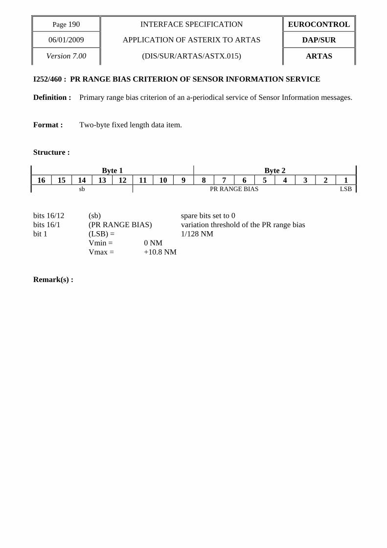
Page 190 INTERFACE SPECIFICATION EUROCONTROL
06/01/2009 APPLICATION OF ASTERIX TO ARTAS DAP/SUR
Version 7.00 (DIS/SUR/ARTAS/ASTX.015) ARTAS
I252/460 : PR RANGE BIAS CRITERION OF SENSOR INFORMATION SERVICE Definition : Primary range bias criterion of an a-periodical service of Sensor Information messages. Format : Two-byte fixed length data item. Structure :
Byte 1 Byte 2 16 15 14 13 12 11 10 9 8 7 6 5 4 3 2 1
sb PR RANGE BIAS LSB bits 16/12 (sb) spare bits set to 0 bits 16/1 (PR RANGE BIAS) variation threshold of the PR range bias bit 1 (LSB) = 1/128 NM Vmin = 0 NM Vmax = +10.8 NM
Remark(s) :

EUROCONTROL INTERFACE SPECIFICATION Page 191
DAP/SUR APPLICATION OF ASTERIX TO ARTAS 06/01/2009
ARTAS (DIS/SUR/ARTAS.ASTX.015) Version 7.00
I252/470 : PR RANGE GAIN CRITERION OF SENSOR INFORMATION SERVICE Definition : Primary range gain criterion of an a-periodical service of Sensor Information messages. Format : Three-byte fixed length data item. Structure :
Byte 1
24 23 22 21 20 19 18 17 sb
Byte 2 Byte 3 16 15 14 13 12 11 10 9 8 7 6 5 4 3 2 1
PR RANGE GAIN LSB bits 24/21 (sb) spare bits set to 0 bits 20/1 (PR RANGE GAIN) variation threshold of the PR range gain bit 1 (LSB) = 10-6 Vmin = 0 Vmax = 1
Remark(s) :

Page 192 INTERFACE SPECIFICATION EUROCONTROL
06/01/2009 APPLICATION OF ASTERIX TO ARTAS DAP/SUR
Version 7.00 (DIS/SUR/ARTAS/ASTX.015) ARTAS
I252/480 : PR AZIMUTH BIAS CRITERION OF SENSOR INFORMATION SERVICE Definition : Primary azimuth bias criterion of an a-periodical service of Sensor Information
messages. Format : Two-byte fixed length data item. Structure :
Byte 1 Byte 2
16 15 14 13 12 11 10 9 8 7 6 5 4 3 2 1 PR AZIMUTH BIAS LSB
bits 16/1 (PR AZIMUTH BIAS) variation threshold of the PR azimuth bias bit 1 (LSB) = 360°/(216) ≅ 0.0055° Vmin = 0° Vmax = 360° - (360° / 216) Remark(s) :

EUROCONTROL INTERFACE SPECIFICATION Page 193
DAP/SUR APPLICATION OF ASTERIX TO ARTAS 06/01/2009
ARTAS (DIS/SUR/ARTAS.ASTX.015) Version 7.00
5.3 Connection to ARTAS 5.3.1 UAP for connection related messages The following User Application Profile shown in Table 9 shall be used for the transmission of connection related messages.
Table 9 - UAP for the connection related messages
FRN Data Item Information Length 1 I252/010 SERVER IDENTIFICATION TAG 2 2 I252/015 USER NUMBER 2 3 I252/020 TIME OF MESSAGE 3 4 I252/035 TYPE OF MESSAGE 1 5 I252/100 CONNECTION RELATED
REPORT 1≤n≤255 1+(nx1)
6 I252/040 ACCESS KEY 8 7 I252/045 ROLE AND VERSION 1
FX - Field extension indicator - 8 I252/050 DEFAULT CONNECTION OPTIONS 1 9 I252/060 GEOGRAPHICAL AREA 3≤n≤50 1+(nx6) 10 I252/070 LOWER LIMIT 2 11 I252/080 UPPER LIMIT 2 12 I252/090 PREFERRED FPPS IDENTIFICATION TAG 2 13 I252/340 SCALING FACTOR 1 14 I252/RE Reserved Expansion Field 1+ FX - Field extension indicator -
In the above table : . the first column indicates the Field Reference Number (FRN) associated to each Data Items
used in the UAP, . the fourth column gives the format and the length of each Item, a stand-alone figure indicates
the byte-count of a fixed length Data item, 1+(nxi) indicates a variable length Data item comprising a first part of 1-byte followed by an extension of up to n times i-bytes (n determined by the amount of information to be transmitted).

Page 194 INTERFACE SPECIFICATION EUROCONTROL
06/01/2009 APPLICATION OF ASTERIX TO ARTAS DAP/SUR
Version 7.00 (DIS/SUR/ARTAS/ASTX.015) ARTAS
5.3.2 Encoding rules
Data Item Reference Number
Description
Presence of items according to the type of message C = Compulsory O = Optional
11 12 13 I252/010 SERVER IDENTIFICATION TAG C C C I252/015 USER NUMBER C C C I252/020 TIME OF MESSAGE C C C I252/035 TYPE OF MESSAGE C C C I252/040 ACCESS KEY C I252/045 ROLE AND VERSION C I252/050 DEFAULT CONNECTION OPTIONS O I252/060 GEOGRAPHICAL AREA O I252/070 LOWER LIMIT O I252/080 UPPER LIMIT O I252/090 PREFERRED FPPS IDENTIFICATION TAG O I252/100 CONNECTION RELATED REPORT C I252/340 SCALING FACTOR O
Message types : $11 = request for connection $12 = request for disconnection $13 = connection related report In case of a request for connection, the following items are incompatible : • I252/060 and UDI bit of I252/050 set to 0 or 1 • I252/070 and LOW bit of I252/050 set to 0 • I252/080 and UPP bit of I252/050 set to 0 • I252/090 and FPP bit of I252/050 set to 0

EUROCONTROL INTERFACE SPECIFICATION Page 195
DAP/SUR APPLICATION OF ASTERIX TO ARTAS 06/01/2009
ARTAS (DIS/SUR/ARTAS.ASTX.015) Version 7.00
5.4 Track and Sensor Information Service 5.4.1 UAP for service related messages The following User Application Profile shown in Table 10 shall be used for the transmission of service related messages.

Page 196 INTERFACE SPECIFICATION EUROCONTROL
06/01/2009 APPLICATION OF ASTERIX TO ARTAS DAP/SUR
Version 7.00 (DIS/SUR/ARTAS/ASTX.015) ARTAS
Table 10 - UAP for the service related messages
FRN Data Item Information Length 1 I252/010 SERVER IDENTIFICATION TAG 2 2 I252/015 USER NUMBER 2 3 I252/020 TIME OF MESSAGE 3 4 I252/035 TYPE OF MESSAGE 1 5 I252/110 SERVICE IDENTIFICATION 1+
(1x1) 6 I252/330 SERVICE RELATED REPORT 1≤n≤255 1+(nx2) 7 I252/210 ITEM SELECTOR 0≤n≤7 2+(nx2)
FX - Field extension indicator - 8 I252/220 CYCLICAL UPDATE CHARACTERISTICS 5 9 I252/200 TRACK/FLIGHT CATEGORIES SELECTOR 4 10 I252/130 TRACK NUMBER SELECTOR 1≤n≤5 1+(nx2) 11 I252/140 CODE FAMILY SELECTOR 1≤n≤5 1+(nx2) 12 I252/120 CALLSIGN SELECTOR 1≤n≤5 1+(nx7) 13 I252/150 DEPARTURE AIRPORT SELECTOR 1≤n≤5 1+(nx4) 14 I252/160 DESTINATION AIRPORT SELECTOR 1≤n≤5 1+(nx4) FX - Field extension indicator
15 I252/060 GEOGRAPHICAL AREA 3≤n≤50 1+(nx6) 16 I252/170 AIRCRAFT TYPE SELECTOR 1≤n≤5 1+(nx4) 17 I252/190 CURRENT CONTROL POSITION SELECTOR 2 18 I252/230 RADAR SYNCHRONISATION CHARACTERISTICS 3+ 19 I252/320 MINIMAL PERIOD 1 20 I252/310 REFRESHMENT PERIOD 1 21 I252/240 DISCRETE PARAMETERS FLAGS 2+ FX - Field extension indicator -
22 I252/270 HEADING CRITERION 1 23 I252/280 SPEED MODULE CRITERION 1 24 I252/290 ALTITUDE CRITERION 1 25 I252/260 POSITION CRITERION 1 26 I252/250 MOF PROBABILITY CRITERION 1 27 I252/300 FACTOR K 1 28 I252/255 RATE OF CLIMB/DESCENT CRITERION 2 FX - Field extension indicator -
29 I252/265 RATE OF TURN CRITERION 1 30 I252/070 LOWER LIMIT 2 31 I252/080 UPPER LIMIT 2 32 I252/135 AIRCRAFT ADDRESS SELECTOR 1≤n≤5 1+(nx3) 33 I252/137 AIRCRAFT IDENTIFICATION SELECTOR 1≤n≤5 1+(nx6) 34 I252/350 SENSOR SELECTOR 1≤n≤30 1+(nx2) 35 I252/360 SENSOR ITEM SELECTOR 2 FX - Field extension indicator -

EUROCONTROL INTERFACE SPECIFICATION Page 197
DAP/SUR APPLICATION OF ASTERIX TO ARTAS 06/01/2009
ARTAS (DIS/SUR/ARTAS.ASTX.015) Version 7.00
36 I252/370 PERIODICAL CHARACTERISTICS OF SENSOR
INFORMATION SERVICE 2
37 I252/400 REFRESHMENT PERIOD OF SENSOR INFORMATION SERVICE
2
38 I252/410 DISCRETE PARAMETERS OF SENSOR INFORMATION SERVICE
1
39 I252/420 TIME STAMPING CRITERION OF SENSOR INFORMATION SERVICE
2
40 I252/430 SSR RANGE BIAS CRITERION OF SENSOR INFORMATION SERVICE
2
41 I252/440 SSR RANGE GAIN CRITERION OF SENSOR INFORMATION SERVICE
3
42 I252/450 SSR AZIMUTH BIAS CRITERION OF SENSOR INFORMATION SERVICE
2
FX - Field extension indicator -
43 I252/460 PR RANGE BIAS CRITERION OF SENSOR INFORMATION SERVICE
2
44 I252/470 PR RANGE GAIN CRITERION OF SENSOR INFORMATION SERVICE
3
45 I252/480 PR AZIMUTH BIAS CRITERION OF SENSOR INFORMATION SERVICE
2
46 - - 47 - - 48 - - 49 I252/RE Reserved Expansion Field 1+ FX - Field extension indicator -
In the above table : . the first column indicates the Field Reference Number (FRN) associated to each Data Items
used in the UAP, . the fourth column gives the format and the length of each Item. A stand-alone figure indicates
the byte-count of a fixed length Data item. j+(nxi) indicates a variable length Data item comprising a first part of j-bytes followed by an extension of up to n times i-bytes (n determined by the amount of information to be transmitted). j+ alone indicates that the item has been designed as a variable length data item in anticipation of possible future extensions.

Page 198 INTERFACE SPECIFICATION EUROCONTROL
06/01/2009 APPLICATION OF ASTERIX TO ARTAS DAP/SUR
Version 7.00 (DIS/SUR/ARTAS/ASTX.015) ARTAS
5.4.2 Encoding rules
Data Item Reference Number
Description
Presence of items according to the type of message C = Compulsory O = Optional
21 22 23 24 25 26 27 28 31 32 33 41 42 43 44 I252/010 SERVER IDENTIFICATION TAG C C C C C C C C C C C C C C C I252/015 USER NUMBER C C C C C C C C C C C C C C C I252/020 TIME OF MESSAGE C C C C C C C C C C C C C C C I252/035 TYPE OF MESSAGE C C C C C C C C C C C C C C C I252/060 GEOGRAPHICAL AREA O O O O O I252/070 LOWER LIMIT O O O O O I252/080 UPPER LIMIT O O O O O I252/110 SERVICE IDENTIFICATION C C C C C C C C C C I252/120 CALLSIGN SELECTOR O O O O O I252/130 TRACK NUMBER SELECTOR O O O O O I252/135 AIRCRAFT ADDRESS
SELECTOR O O O O O
I252/137 AIRCRAFT IDENTIFICATION SELECTOR
O O O O O
I252/140 CODE FAMILY SELECTOR O O O O O I252/150 DEPARTURE AIRPORT
SELECTOR O O O O O
I252/160 DESTINATION AIRPORT SELECTOR
O O O O O
I252/190 CURRENT CONTROL POSITION SELECTOR
O O O O O
I252/200 TRACK/FLIGHT CATEGORIES SELECTOR
O O O O O
I252/210 ITEM SELECTOR C C C O O I252/220 CYCLICAL UPDATE
CHARACTERISTICS O O
I252/230 RADAR SYNCHRONISATION CHARACTERISTICS
O
I252/240 DISCRETE PARAMETERS FLAGS
O O O
I252/250 MOF PROBABILITY CRITERION O O O I252/255 RATE OF CLIMB/DESCENT
CRITERION O O O
I252/260 POSITION CRITERION O O O I252/265 RATE OF TURN CRITERION O O O I252/270 HEADING CRITERION O O O I252/280 SPEED MODULE CRITERION O O O I252/290 ALTITUDE CRITERION O O O I252/300 FACTOR K O O O I252/310 REFRESHMENT PERIOD O O O I252/320 MINIMAL PERIOD O O O I252/330 SERVICE RELATED REPORT C C C I252/350 SENSOR SELECTOR O I252/360 SENSOR ITEM SELECTOR C I252/370 PERIODICAL
CHARACTERISTICS OF SENSOR INFORMATION SERVICE
O
I252/400 REFRESHMENT PERIOD OF SENSOR INFORMATION SERVICE
O

EUROCONTROL INTERFACE SPECIFICATION Page 199
DAP/SUR APPLICATION OF ASTERIX TO ARTAS 06/01/2009
ARTAS (DIS/SUR/ARTAS.ASTX.015) Version 7.00
Data Item Reference Number
Description
Presence of items according to the type of message C = Compulsory O = Optional
21 22 23 24 25 26 27 28 31 32 33 41 42 43 44 I252/410 DISCRETE PARAMETERS OF
SENSOR INFORMATION SERVICE
O
1252/420 TIME STAMPING CRITERION OF SENSOR INFORMATION SERVICE
O
I252/430 SSR RANGE BIAS CRITERION OF SENSOR INFORMATION SERVICE
O
I252/440 SSR RANGE GAIN CRITERION OF SENSOR INFORMATION SERVICE
O
I252/450 SSR AZIMUTH BIAS CRITERION OF SENSOR INFORMATION SERVICE
O
I252/460 PR RANGE BIAS CRITERION OF SENSOR INFORMATION SERVICE
O
I252/470 PR RANGE GAIN CRITERION OF SENSOR INFORMATION SERVICE
O
I252/480 PR AZIMUTH BIAS CRITERION OF SENSOR INFORMATION SERVICE
O
Message types :
$ 21 = Background Service Definition, $ 22 = Synchronised Complementary Service Definition, $ 23 = Independent Complementary Service Definition, $ 24 = Service Update/Stop Track/Item transmission, $ 25 = Service Update/Start Track/Item transmission, $ 26 = Service Control/Interruption, $ 27 = Service Control/Restart, $ 28 = Service Control/End of Service, $ 31 = Server Status Message, $ 32 = Track Service Related Report, $ 33 = Sensor Information Service Related Report, $ 41 = Sensor Information Service definition request $ 42 = Service Control Request = Interruption $ 43 = Service Control Request = Restart $ 44 = Service Control Request = End of Service
Message types $31, $32, and $33 are only sent to users using category 30 and 31.

Page 200 INTERFACE SPECIFICATION EUROCONTROL
06/01/2009 APPLICATION OF ASTERIX TO ARTAS DAP/SUR
Version 7.00 (DIS/SUR/ARTAS/ASTX.015) ARTAS
I252/220 (cyclical transmission characteristics), I252/230 (radar synchronised transmission characteristics) and any subset of {I252/240, I252/250, I252/255, I252/260, I252/265, I252/270, I252/280, I252/290, I252/300, I252/310, I252/320} (a-periodical transmission characteristics) are mutually exclusive, in case of background/complementary service definition (message type 21, 22, 23). Any subset of {I252/060, I252/070, I252/080} (geographical track selector), any subset of {I252/120, I252/130, I252/135, I252/137, I252/140, I252/150, I252/160, I252/170, I252/190, I252/200} (non geographical track selector) and I252/210 (item selector) are mutually exclusive in case of service update (message type 24 and 25). I252/370 (periodical characteristics of sensor information service) and any subset of {I252/400, I252/410, I252/420, I252/430, I252/440, I252/450, I252/460, I252/470, I252/480}(a-periodical characteristics of sensor information service) are optional and mutually exclusive in case of sensor information service definition (message type 41).

EUROCONTROL INTERFACE SPECIFICATION Page 201
DAP/SUR APPLICATION OF ASTERIX TO ARTAS 06/01/2009
ARTAS (DIS/SUR/ARTAS.ASTX.015) Version 7.00
6 Summary of Modifications The changes between version 6.1 and 6.2 are listed below: ACP 143:
• I252/330. Report code 57 has been marked as 'no longer used'. It is not used by ARTAS.
ACP 145:
• A new paragraph has been added to the introduction to describe the general rule for when field extents are sent.
• I030/080. The SF bit has been redefined slightly and a third remark has been added to clarify that the third extent if a track coding precision of 1/64Nm is used.
ACP 179:
• A remark has been added to I030/220.
ATR 692:
• The range for I252/450 and I252/480 have been changed.
The changes between version 6.2 and AA02 are listed below: • The Introduction has been changed to introduce the new ASTERIX standard categories being used
as from the version V7A0 of ARTAS..
• The track/Flight Categories Selector has been updated (I252/200) to include track selectors for ADS-B.
• The item selector (I252/210) has been updated to reflect the data items available in Category 62 (version 0.28).
• The Sensor Item Selector (item I252/360) has been updated to reflect the data items available in Category 63 (version 0.18).
• The discrete parameter flag (I252/240) has been updated to include an a-periodic trigger to forward every track update received from the tracker.
• ACP 212: A new data item has been added to category 32 to include the additional flight data that is supported by category 62 but that were not available in preceding definition of category 32.
The changes between version AA02 and AA03 are listed below: • I252/210 Item selectors has been updated to include the selection of individual sub fields of
item I062/390, and the additional DAPs added to item I062/380, plus their associated ages in I062/295.
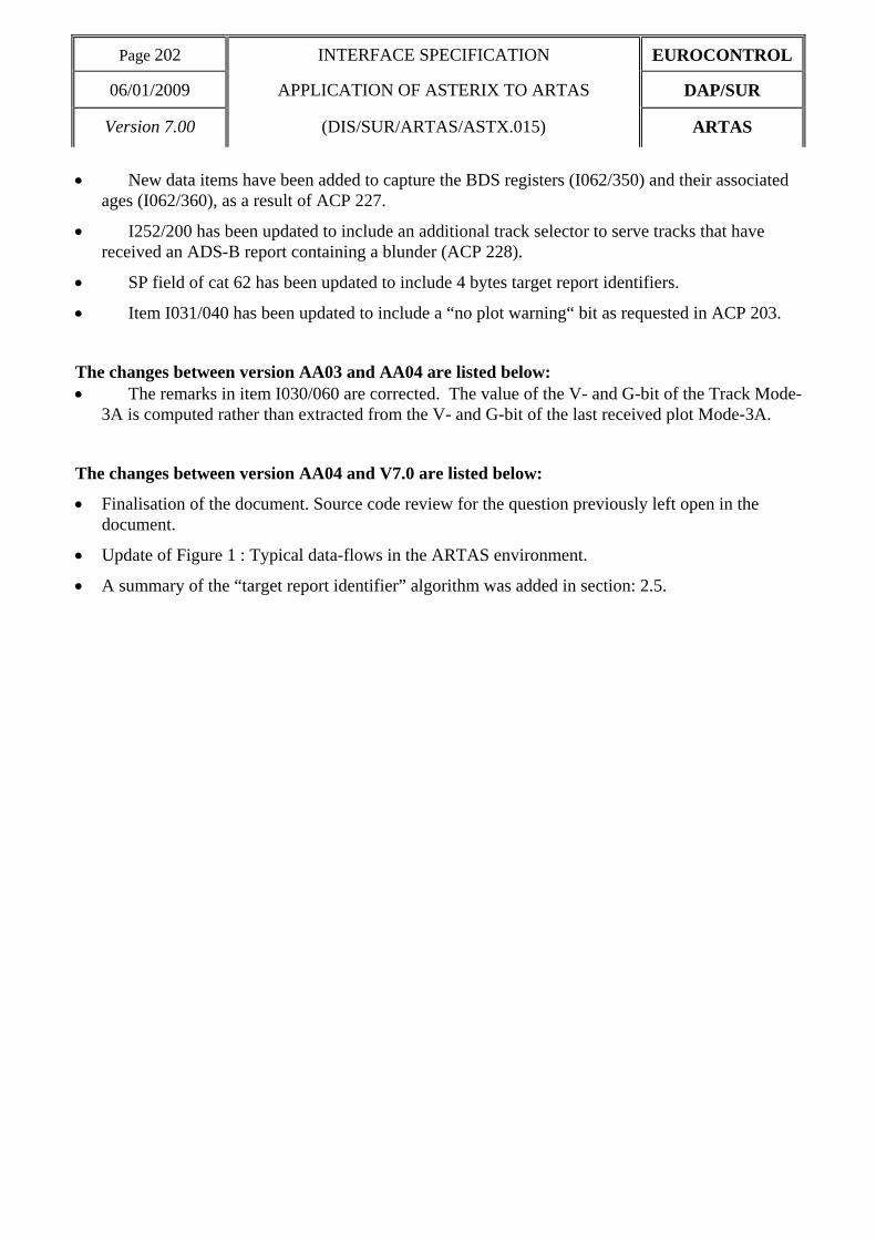
Page 202 INTERFACE SPECIFICATION EUROCONTROL
06/01/2009 APPLICATION OF ASTERIX TO ARTAS DAP/SUR
Version 7.00 (DIS/SUR/ARTAS/ASTX.015) ARTAS
• New data items have been added to capture the BDS registers (I062/350) and their associated ages (I062/360), as a result of ACP 227.
• I252/200 has been updated to include an additional track selector to serve tracks that have received an ADS-B report containing a blunder (ACP 228).
• SP field of cat 62 has been updated to include 4 bytes target report identifiers.
• Item I031/040 has been updated to include a “no plot warning“ bit as requested in ACP 203.
The changes between version AA03 and AA04 are listed below: • The remarks in item I030/060 are corrected. The value of the V- and G-bit of the Track Mode-
3A is computed rather than extracted from the V- and G-bit of the last received plot Mode-3A.
The changes between version AA04 and V7.0 are listed below:
• Finalisation of the document. Source code review for the question previously left open in the document.
• Update of Figure 1 : Typical data-flows in the ARTAS environment.
• A summary of the “target report identifier” algorithm was added in section: 2.5.