Embed Size (px)
Citation preview

<GSM Looped based BER and TX measurements using ARB files on the R&S CMW 500> Application Note
Products:
| R&S CMW500
| R&S CMW-KW200
| R&S CMW-KM200
<App
licati
onNo
te>
<Tho
masL
utz>
<05.2
010-
1CM8
7>-<
versi
on0.1
>

Table of Contents
<1CM87_0E> Rohde & Schwarz <GSM Looped based BER and TX measurements, using ARB files on the R&S CMW 500> 2
Table of Contents 1 Test Equipment Setup ........................................................... 4 1.1 R&S CMW500 GSM Arbitrary Waveform Playback Setup.......................4 1.1.1 Step 1 – Enable the General Purpose RF Generator ................................4 1.1.2 Step 2 – Configure the General Purpose RF Generator ...........................5 1.1.3 Step 3 – Select the ARB File........................................................................5 1.1.4 Step 4 – Turn ON the General Purpose RF Generator..............................6 1.1.5 – Table of the General Purpose RF Generator Settings...........................7 1.1.6 Rohde & Schwarz GSM Non-signaling test arbitrary waveform
configuration.................................................................................................7 1.1.6.1 Other setup notes.......................................................................................10 1.1.7 R&S CMW500 Configuration for GSM Uplink Signal Measurement ....10 1.1.8 Multi Evaluation Settings...........................................................................11 1.1.9 RF Settings..................................................................................................11 1.1.10 Measurement Control ................................................................................15 1.1.10.1 Repetition ....................................................................................................15 1.1.10.2 Stop Condition............................................................................................16 1.1.10.3 Statistic Counts ..........................................................................................16 1.1.10.4 Measurement Slots ....................................................................................16 1.1.10.5 Assign View ................................................................................................17 1.1.11 Start the Measurement...............................................................................17 1.1.12 Measurement Results Screen Shots ........................................................17 1.1.13 Automating a GSM Measurement with the R&S CMW500....................20 1.1.13.1 Configure the arbitrary signal generator to play the waveform ............20 1.1.13.2 Configure the R&SCMW500 analyzer to make a GSM measurement .20 1.1.13.3 Configure the trigger condition for the GSM measurement ..................21 1.1.13.4 Arm the measurement ...............................................................................21 1.1.13.5 Get the power measurement results ........................................................21 1.1.13.6 Get the averaged modulation measurement results ..............................21 1.1.13.7 Get the spectrum measurement results ..................................................21 1.1.13.8 Get the BER measurement results ...........................................................21
2 Summary............................................................................... 22
3 References............................................................................ 22

Table of Contents
<1CM87_0E> Rohde & Schwarz <GSM Looped based BER and TX measurements, using ARB files on the R&S CMW 500> 3
Test Equipment Setup
<1CM87_0E> Rohde & Schwarz <GSM Looped based BER and TX measurements, using ARB files on the R&S CMW 500> 4
1 Test Equipment Setup
1.1 R&S CMW500 GSM Arbitrary Waveform Playback Setup
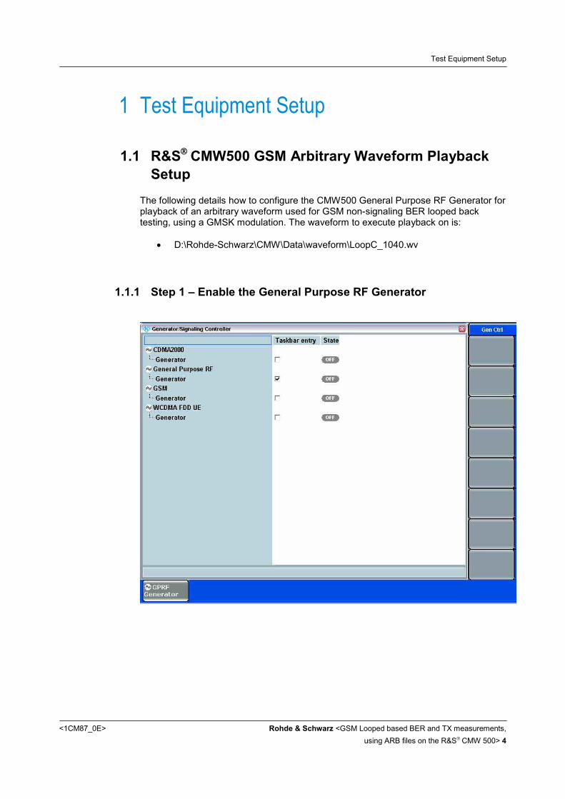
The following details how to configure the CMW500 General Purpose RF Generator for playback of an arbitrary waveform used for GSM non-signaling BER looped back testing, using a GMSK modulation. The waveform to execute playback on is:
• D:\Rohde-Schwarz\CMW\Data\waveform\LoopC_1040.wv
1.1.1 Step 1 – Enable the General Purpose RF Generator

Test Equipment Setup
<1CM87_0E> Rohde & Schwarz <GSM Looped based BER and TX measurements, using ARB files on the R&S CMW 500> 5
1.1.2 Step 2 – Configure the General Purpose RF Generator
1.1.3 Step 3 – Select the ARB File
To select the arbitrary waveform, press the ARB soft key on left side of R&S CMW screen, followed by the “Select ARB File …” soft key on the bottom

Test Equipment Setup
<1CM87_0E> Rohde & Schwarz <GSM Looped based BER and TX measurements, using ARB files on the R&S CMW 500> 6
Navigate through the pop up dialog, e.g. rotating the spin wheel and select the desired arbitrary waveform file by pushing the spin wheel. Navigate the focus of the dialog to the OK button by rotating the spin wheel again. After selecting the OK button push the spin wheel again
1.1.4 Step 4 – Turn ON the General Purpose RF Generator
To begin playing the arbitrary waveform, press the On/Off hard key button on the R&S CMW500 front panel, located along the top of the instrument, above the spin wheel.
Test Equipment Setup
<1CM87_0E> Rohde & Schwarz <GSM Looped based BER and TX measurements, using ARB files on the R&S CMW 500> 7
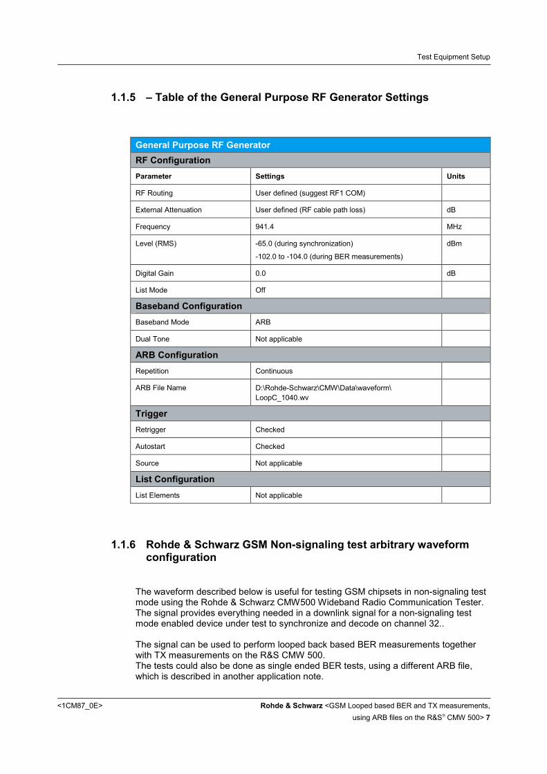
1.1.5 – Table of the General Purpose RF Generator Settings
General Purpose RF Generator RF Configuration Parameter Settings Units
RF Routing User defined (suggest RF1 COM)
External Attenuation User defined (RF cable path loss) dB
Frequency 941.4 MHz
Level (RMS) -65.0 (during synchronization)
-102.0 to -104.0 (during BER measurements)
dBm
Digital Gain 0.0 dB
List Mode Off
Baseband Configuration Baseband Mode ARB
Dual Tone Not applicable
ARB Configuration Repetition Continuous
ARB File Name D:\Rohde-Schwarz\CMW\Data\waveform\ LoopC_1040.wv
Trigger Retrigger Checked
Autostart Checked
Source Not applicable
List Configuration List Elements Not applicable
1.1.6 Rohde & Schwarz GSM Non-signaling test arbitrary waveform configuration
The waveform described below is useful for testing GSM chipsets in non-signaling test mode using the Rohde & Schwarz CMW500 Wideband Radio Communication Tester. The signal provides everything needed in a downlink signal for a non-signaling test mode enabled device under test to synchronize and decode on channel 32.. The signal can be used to perform looped back based BER measurements together with TX measurements on the R&S CMW 500. The tests could also be done as single ended BER tests, using a different ARB file, which is described in another application note.

Test Equipment Setup
<1CM87_0E> Rohde & Schwarz <GSM Looped based BER and TX measurements, using ARB files on the R&S CMW 500> 8
Uplink signal measurements from the chip can be performed using the CMW500 GSM measurement option, KM200. Waveform file name: LoopC_1040.wv Waveform Content 4800 millisecond long waveform (1040 frames)
A BCCH channel, containing a 51 multi-frame structure on slot 0
Seven parallel signals , running a TCH 26 multi-frame structure on slots 1 to 7
Providing multi-slot support
Full rate speech channel coded data
The traffic data is a constant ‘01’ bit pattern
BCCH and TCH channels are transmitted with the same power
Base station color code 0
The next graphic illustrates the frame structure of the signal. Timing wise, starting with slot 0 of frame 0 a frequency correction burst (FCC) is transmitted followed by a traffic channel (TCH) on slot 1 of frame 0. The signal on slot 0 represents a complete C0 multi-frame signal. With the wrap around of the ARB signal on frame 1039 the BCCH multi-frame is incomplete, as 1040 frames are not dividable by 51 without a reminder. The length of the traffic channel (TCH) signals are 40 TCH multi-frames long (40 x 26 = 1040 frames), before the signal wraps around. The signal content of slot 1 to slot 7 is identical.

Test Equipment Setup
<1CM87_0E> Rohde & Schwarz <GSM Looped based BER and TX measurements, using ARB files on the R&S CMW 500> 9
Slot 1 Slot 2 Slot 3 Slot 4 Slot 5 Slot 6 Slot 7 Slot 0 TCH TCH TCH TCH TCH TCH TCH FCC Frame 0 TCH TCH TCH TCH TCH TCH TCH SYNC Frame 1 TCH TCH TCH TCH TCH TCH TCH BCC Frame 2 TCH TCH TCH TCH TCH TCH TCH BCC Frame 3 TCH TCH TCH TCH TCH TCH TCH BCC Frame 4 TCH TCH TCH TCH TCH TCH TCH BCC Frame 5 TCH TCH TCH TCH TCH TCH TCH CCCH Frame 6 TCH TCH TCH TCH TCH TCH TCH CCCH Frame 7 TCH TCH TCH TCH TCH TCH TCH CCCH Frame 8 TCH TCH TCH TCH TCH TCH TCH CCCH Frame 9 TCH TCH TCH TCH TCH TCH TCH FCC Frame 10 TCH TCH TCH TCH TCH TCH TCH SYNC Frame 11
SACCH1 SACCH1 SACCH1 SACCH1 SACCH1 SACCH1 SACCH1CCCH Frame 12 TCH TCH TCH TCH TCH TCH TCH CCCH Frame 13 TCH TCH TCH TCH TCH TCH TCH CCCH Frame 14 TCH TCH TCH TCH TCH TCH TCH CCCH Frame 15 TCH TCH TCH TCH TCH TCH TCH CCCH Frame 16 TCH TCH TCH TCH TCH TCH TCH CCCH Frame 17 TCH TCH TCH TCH TCH TCH TCH CCCH Frame 18 TCH TCH TCH TCH TCH TCH TCH CCCH Frame 19 TCH TCH TCH TCH TCH TCH TCH FCC Frame 20 TCH TCH TCH TCH TCH TCH TCH SYNC Frame 21 TCH TCH TCH TCH TCH TCH TCH CCCH Frame 22 TCH TCH TCH TCH TCH TCH TCH CCCH Frame 23 TCH TCH TCH TCH TCH TCH TCH CCCH Frame 24 IDLE2 IDLE2 IDLE2 IDLE2 IDLE2 IDLE2 IDLE2CCCH Frame 25 TCH TCH TCH TCH TCH TCH TCH CCCH Frame 26 TCH TCH TCH TCH TCH TCH TCH CCCH Frame 27 TCH TCH TCH TCH TCH TCH TCH CCCH Frame 28 TCH TCH TCH TCH TCH TCH TCH CCCH Frame 29 TCH TCH TCH TCH TCH TCH TCH FCC Frame 30 TCH TCH TCH TCH TCH TCH TCH SYNC Frame 31 TCH TCH TCH TCH TCH TCH TCH CCCH Frame 32 TCH TCH TCH TCH TCH TCH TCH CCCH Frame 33 TCH TCH TCH TCH TCH TCH TCH CCCH Frame 34 TCH TCH TCH TCH TCH TCH TCH CCCH Frame 35 TCH TCH TCH TCH TCH TCH TCH CCCH Frame 36 TCH TCH TCH TCH TCH TCH TCH CCCH Frame 37
SACCH1 SACCH1 SACCH1 SACCH1 SACCH1 SACCH1 SACCH1CCCH Frame 38 TCH TCH TCH TCH TCH TCH TCH CCCH Frame 39 TCH TCH TCH TCH TCH TCH TCH FCC Frame 40 TCH TCH TCH TCH TCH TCH TCH SYNC Frame 41 TCH TCH TCH TCH TCH TCH TCH CCCH Frame 42 TCH TCH TCH TCH TCH TCH TCH CCCH Frame 43 TCH TCH TCH TCH TCH TCH TCH CCCH Frame 44 TCH TCH TCH TCH TCH TCH TCH CCCH Frame 45 TCH TCH TCH TCH TCH TCH TCH CCCH Frame 46 TCH TCH TCH TCH TCH TCH TCH CCCH Frame 47 TCH TCH TCH TCH TCH TCH TCH CCCH Frame 48 TCH TCH TCH TCH TCH TCH TCH CCCH Frame 49 TCH TCH TCH TCH TCH TCH TCH IDLE2Frame 50 IDLE2 IDLE2 IDLE2 IDLE2 IDLE2 IDLE2 IDLE2FCC Frame 51 TCH TCH TCH TCH TCH TCH TCH SYNC Frame 52 TCH TCH TCH TCH TCH TCH TCH BCC Frame 53 TCH TCH TCH TCH TCH TCH TCH BCC Frame 54 TCH TCH TCH TCH TCH TCH TCH BCC Frame 55 TCH TCH TCH TCH TCH TCH TCH BCC Frame 56 TCH TCH TCH TCH TCH TCH TCH CCCH Frame 57 TCH TCH TCH TCH TCH TCH TCH CCCH Frame 58 TCH TCH TCH TCH TCH TCH TCH CCCH Frame 59
… … … … … … ……Frame …
IDLE2 IDLE2 IDLE2 IDLE2 IDLE2 IDLE2 IDLE2CCCH Frame 1039 TCH TCH TCH TCH TCH TCH TCH FCC Frame 0
1) The SACCH is replaced by a dummy burst 2) The IDLE is replaced by a dummy burst

Test Equipment Setup
<1CM87_0E> Rohde & Schwarz <GSM Looped based BER and TX measurements, using ARB files on the R&S CMW 500> 10
1.1.6.1 Other setup notes
It is required to have the BCCH and the TCH at the same channel and the same level
1.1.7 R&S CMW500 Configuration for GSM Uplink Signal Measurement
The following describes how to configure the R&S CMW500 to perform a measurement on the uplink GSM transmitter. First, enable the GSM TX Measurement option on, by checking its enable radio button from the Measurement Controller sub panel. This menu can be found by pressing the Measure hard key found along the top of the R&S CMW500 front panel, above the number keypad.

Test Equipment Setup
<1CM87_0E> Rohde & Schwarz <GSM Looped based BER and TX measurements, using ARB files on the R&S CMW 500> 11
1.1.8 Multi Evaluation Settings
Next find and press the following soft key on from the CMW500 GSM TX Measurement – Multi Evaluation screen. If this soft key is not yet visible, use the Tasks hard key.
The Tasks hard key shows the available currently enabled (loaded) software features and to select this feature. Press the soft key “GSM Multi Eval.”
The displayed soft keys row along the bottom of the LCD display should change to one of the GSM Multi Evaluation controls like shown below.
1.1.9 RF Settings
Press the “Config…” on the right side of the displayed soft keys row along the bottom of the LCD display. You should see the shown pop up menu now.

Test Equipment Setup
<1CM87_0E> Rohde & Schwarz <GSM Looped based BER and TX measurements, using ARB files on the R&S CMW 500> 12
Use the spin wheel to scroll down in the configuration pop up window to the position, where the BER parameter become visible. Change the BER loop type to “C”

Test Equipment Setup
<1CM87_0E> Rohde & Schwarz <GSM Looped based BER and TX measurements, using ARB files on the R&S CMW 500> 13
The following screen shots detail how to configure the following parameters to these values:

Test Equipment Setup
<1CM87_0E> Rohde & Schwarz <GSM Looped based BER and TX measurements, using ARB files on the R&S CMW 500> 14
GSM Measurements RF Configuration Parameter Settings Units
RF Routing User defined (suggest RF1 COM)
External Attenuation User defined (RF cable path loss) dB
Frequency 896.4 MHz
Expected Power Level (RMS) 33.0 dBm
User Margin 2.0 dB
List Mode Off
Trigger Trigger Source Power
Trigger Slope Rising Edge
Trigger Threshold -30.0 dB
Trigger Delay 0 slots
Trigger Timeout 1000 (default) msec.
Minimum Trigger Gap 1) slot
Statistic Counts Power 1 Frames
Modulation 5 Frames
Spectrum due to Switching
10 Frames
Spectrum due to Modulation
30 Frames
BER 88 (corresponds to 10 kBit) Frames
List Configuration List Elements Not applicable
Press the soft key “Config…” again to come back to the measurement screen. The R&S CMW500 LCD screen should look like the following:

Test Equipment Setup
<1CM87_0E> Rohde & Schwarz <GSM Looped based BER and TX measurements, using ARB files on the R&S CMW 500> 15
1.1.10 Measurement Control
Find and press the following soft key on the right-hand column of the LCD screen.
Configure the remaining parameters by manipulating the soft keys as such:
1.1.10.1 Repetition
Set the repetition mode to “Continuous”

Test Equipment Setup
<1CM87_0E> Rohde & Schwarz <GSM Looped based BER and TX measurements, using ARB files on the R&S CMW 500> 16
1.1.10.2 Stop Condition
Set the stop condition to “None”
1.1.10.3 Statistic Counts
1.1.10.4 Measurement Slots

Test Equipment Setup
<1CM87_0E> Rohde & Schwarz <GSM Looped based BER and TX measurements, using ARB files on the R&S CMW 500> 17
1.1.10.5 Assign View
Press the soft key “Assign Views…” to select the TX measurements of your interest, including a loop based BER
1.1.11 Start the Measurement
The measurement can be manually executed (triggered) by pressing the ON/OFF hard key on the front panel of the R&S CMW500, located along the top of the instrument, above the spin wheel.
1.1.12 Measurement Results Screen Shots

Test Equipment Setup
<1CM87_0E> Rohde & Schwarz <GSM Looped based BER and TX measurements, using ARB files on the R&S CMW 500> 18
A successful GSM multi-evaluation measurement on the R&S CMW500 should look something like found on the following screen shot.
Find and press the following soft key on the right-hand column of the LCD screen.
In combination with the soft key “Select View” on the bottom of the display more details for single TX measurements can be visualized.
The following screen shots demonstrate such measurement views

Test Equipment Setup
<1CM87_0E> Rohde & Schwarz <GSM Looped based BER and TX measurements, using ARB files on the R&S CMW 500> 19

Test Equipment Setup
<1CM87_0E> Rohde & Schwarz <GSM Looped based BER and TX measurements, using ARB files on the R&S CMW 500> 20
1.1.13 Automating a GSM Measurement with the R&S CMW500
The following SCPI command code is an example of how to configure the R&S
CMW500 signal generator and signal analyzer to perform a non-signaling GSM uplink TX measurement on non signaling enabled GSM chipset. The leading “CMW: ” is not part of the command, this is only used as a address symbol in Rohde & Schwarz remote script tools.
1.1.13.1 Configure the arbitrary signal generator to play the waveform
Whenever loading an ARB file, you should ensure it was present on the selected path. The verification can be achieved by querying the currently loaded ARB file. A return string "No File Selected" would be an indication, that the file is not present.
1.1.13.2 Configure the R&SCMW500 analyzer to make a GSM measurement
CMW: ROUT:GSM:MEAS:RFS:CONN RF1C CMW: CONF:GSM:MEAS:RFS:EATT 1 CMW: CONF:GSM:MEAS:RFS:FREQ 896.4e6 CMW: CONF:GSM:MEAS:RFS:ENP 33 CMW: CONF:GSM:MEAS:RFS:UMAR 2 CMW: CONF:GSM:MEAS:MEV:MSL 0, 1, 0 CMW: CONF:GSM:MEAS:MEV:SCO:PVT 1 CMW: CONF:GSM:MEAS:MEV:SCO:MOD 5 CMW: CONF:GSM:MEAS:MEV:SCO:SMOD 30 CMW: CONF:GSM:MEAS:MEV:SCO:SSW 10 CMW: CONF:GSM:MEAS:MEV:SCO:BER 88 CMW: CONF:GSM:MEAS:MEV:BER:LOOP C CMW: CONF:GSM:MEAS:MEV:TSEQ TSC0 CMW: CONF:GSM:MEAS:MEV:RES:PVT ON CMW: CONF:GSM:MEAS:MEV:RES:EVM OFF CMW: CONF:GSM:MEAS:MEV:RES:MERR OFF CMW: CONF:GSM:MEAS:MEV:RES:PERR ON CMW: CONF:GSM:MEAS:MEV:RES:SMFR ON CMW: CONF:GSM:MEAS:MEV:RES:SMT ON CMW: CONF:GSM:MEAS:MEV:RES:SSFR ON CMW: CONF:GSM:MEAS:MEV:RES:SST ON CMW: CONF:GSM:MEAS:MEV:RES:IQ OFF CMW: CONF:GSM:MEAS:MEV:RES:BER ON
CMW: ROUT:GPRF:GEN:RFS:CONN RF1C CMW: SOUR:GPRF:GEN:BBM ARB CMW: SOUR:GPRF:GEN:RFS:FREQ 941.4e6 CMW: SOUR:GPRF:GEN:RFS:EATT 1 CMW: SOUR:GPRF:GEN:RFS:LEV -65 CMW: SOUR:GPRF:GEN:ARB:FILE 'd:\\Rohde-Schwarz\\CMW\\data\\waveform\\LoopC_1040.wv' CMW: SOUR:GPRF:GEN:ARB:FILE? CMW: SOUR:GPRF:GEN:ARB:REP CONT CMW: TRIG:GPRF:GEN:ARB:RETR ON CMW: TRIG:GPRF:GEN:ARB:AUT ON CMW: SOUR:GPRF:GEN:LIST OFF CMW: SYST:ERR? CMW: SOUR:GPRF:GEN1:STAT ON;*OPC?

Test Equipment Setup
<1CM87_0E> Rohde & Schwarz <GSM Looped based BER and TX measurements, using ARB files on the R&S CMW 500> 21
1.1.13.3 Configure the trigger condition for the GSM measurement
1.1.13.4 Arm the measurement
1.1.13.5 Get the power measurement results
1.1.13.6 Get the averaged modulation measurement results
1.1.13.7 Get the spectrum measurement results
1.1.13.8 Get the BER measurement results
CMW: TRIG:GSM:MEAS:MEV:SOUR 'Power' CMW: TRIG:GSM:MEAS:MEV:DEL 0 CMW: TRIG:GSM:MEAS:MEV:TOUT 1 CMW: TRIG:GSM:MEAS:MEV:THR -30.00
CMW: FETC:GSM:MEAS:MEV:BER?
CMW: FETC:GSM:MEAS:MEV:MOD:AVER?
CMW: FETC:GSM:MEAS:MEV:TRAC:SMOD:FREQ? CMW: FETC:GSM:MEAS:MEV:TRAC:SSW:FREQ?
CMW: FETC:GSM:MEAS:MEV:PVT?
CMW: INIT:GSM:MEAS:MEV;*OPC?

Summary
<1CM87_0E> Rohde & Schwarz <GSM Looped based BER and TX measurements, using ARB files on the R&S CMW 500> 22
2 Summary The application note explains how to use an arbitrary waveform file to perform typical GSM transmitter tests in parallel to a looped based BER measurements for a non-signaling test mode enabled device.
3 References [1] User manual of the R&S CMW 500 or R&S CMW 280 radio communication
tester. [2]
Index A
Arm the GSM Measurement .................................................... 21 Automating a GSM Measurement ............................................ 20
CConfigure the ARB generator................................................... 20 Configure the GPRF Generator.................................................. 5 Configure the GSM analyzer.................................................... 20 Configure the trigger condition ................................................. 21
E
Enable the GPRF Generator...................................................... 4
GGet the GSM averaged modulation measurement results ........ 21 Get the GSM BER measurement results.................................. 21 Get the GSM power measurement results ............................... 21 Get the GSM spectrum measurement results .......................... 21
GSM.........................................................................................17 GSM Uplink Measurements......................................................10
M
Measurement Control ...............................................................15 Multi Evaluation Settings ..........................................................11
R
RF Settings of the GSM Measurement .....................................11
S
Select the ARB File ....................................................................5 Select View ..............................................................................18 Start the GSM Measurement ....................................................17
T
Table of the GPRF Generator Settings .......................................7 Turn On the GPRF Generator.....................................................6

About Rohde & Schwarz Rohde & Schwarz is an independent group of companies specializing in electronics. It is a leading supplier of solutions in the fields of test and measurement, broadcasting, radiomonitoring and radiolocation, as well as secure communications. Established 75 years ago, Rohde & Schwarz has a global presence and a dedicated service network in over 70 countries. Company headquarters are in Munich, Germany.
Environmental commitment ● Energy-efficient products ● Continuous improvement in
environmental sustainability ● ISO 14001-certified environmental
management system
Regional contact
USA & Canada USA: 1-888-TEST-RSA (1-888-837-8772) from outside USA: +1 410 910 7800 [email protected]
East Asia +65 65 13 04 88 [email protected]
Rest of the World +49 89 4129 137 74 [email protected]
This application note and the supplied programs may only be used subject to the conditions of use set forth in the download area of the Rohde & Schwarz website.
R&S® is a registered trademark of Rohde & Schwarz GmbH & Co. KG. Trade names are trademarks of the owners.
Rohde & Schwarz GmbH & Co. KG Mühldorfstraße 15 | D - 81671 München Phone + 49 89 4129 - 0 | Fax + 49 89 4129 – 13777 www.rohde-schwarz.com