Embed Size (px)
Citation preview

Application Note
SPURIOUS TESTING OF 5G DEVICES USING EMI RECEIVERS Products: ► R&S®ESW
Jeremy Cline | Rohde & Schwarz | Version 1.00 | 08.2020

Rohde & Schwarz | Application Note Spurious Testing of 5G Devices Using EMI Receivers 2
Contents 1 Overview ........................................................................................................ 3
2 Introduction ................................................................................................... 3
3 Defining RSE ................................................................................................. 4
4 Requirements for 5G RSE Testing ............................................................... 6
5 Value of a Modern EMI Test Receiver .......................................................... 7
6 Solutions from Rohde & Schwarz................................................................ 9
6.1 Versatile capabilities.......................................................................................... 10 6.2 Rohde & Schwarz accessories .......................................................................... 11
7 Conclusion .................................................................................................. 12

Rohde & Schwarz | Application Note Spurious Testing of 5G Devices Using EMI Receivers 3
1 Overview With all eyes on the 5G wave, this application note discusses the challenges that engineers face when it comes to radiated spurious emission (RSE) testing. RSE testing is just one part of performing fully-compliant EMC measurements, however. This paper also aims to provide an overview of the latest features available in EMI test receivers, and why they matter to everyday EMC measurements.
2 Introduction Developers of fifth-generation (5G) wireless technology are chasing an aggressive and impressive vision: amazingly fast data rates, great service in a crowd, best service follows the user, real-time and reliable communications, and ubiquitous devices communicating. In pursuit of this vision, 5G is using multiple frequency bands, all of which are heavily regulated around the world.
Another set of regulations is equally important: electromagnetic compliance (EMC) testing of all 5G equipment. These tests are defined by a variety of standards bodies and regulated by government agencies around the world. If you dig into the 3rd Generation Partnership Project (3GPP) standards for 5G, item 38.113 deals with infrastructure (e.g., base stations) and item 38.124 covers mobile terminals (e.g., user equipment, or UE, and so on). As another example, the United States Federal Communications Commission (FCC) has published three relevant standards—Parts 22, 24 and 27—that include EMC requirements.
Such tests can be especially challenging because a mobile terminal such as a smart phone contains multiple radios that are considered “intentional transmitters” operating in several frequency bands. These include 3GPP FR1 (450 MHz to 6 GHz), 3GPP FR2 (24.5 to 52.6 GHz), Bluetooth and 802.11b/g/n/ax (2.4 GHz), and 802.11a/h/j/n/ac/ax (5.0 GHz).
The subset of EMC called electromagnetic interference (EMI) is concerned with unintentional emissions from these same devices (e.g., harmonics and other mixing products). These transmissions fall into two categories: out-of-band (OOB) emissions, which are adjacent to and immediately above and below the frequency band in use; and radiated spurious emissions (RSE) which are farther out, above and below the frequency band.
This application note focuses on the characterization of RSE as an adjunct to the development of 5G hardware. It will answer the question, “How can EMI test receivers help accelerate time-to-market for 5G designs?” The discussion concludes with an overview of solutions available from Rohde & Schwarz.

Rohde & Schwarz | Application Note Spurious Testing of 5G Devices Using EMI Receivers 4
3 Defining RSE Radiated spurious emissions typically come from an intentional transmitter (or radiator) that is also emanating unintentional RF energy. A word-by-word break down of this phrase adds useful context:
► Radiated signals are transmitted over the air; this is in contrast to conducted signals carried on wires
► Spurious signals (i.e., “spurs”) refer to all frequency content other than the fundamental, and these exist beyond (above and below) the OOB emissions
► Emissions refers to all radiated signals including harmonics, other mixing products, and spurious
Figure 1 illustrates the relationship between OOB emissions and spurious emissions relative to the frequency band of interest.
Figure 1: A “good citizen” emitter should have minimal RSE in the bands beyond f0 ± 2.5 * fBW.1
This is not a new concept. For decades, many types of RSE tests have been required around the world (e.g., GSM, industrial, scientific and medical (ISM) band). Today, the following examples are among the required tests:
► 3GPP TS51.010 / ETSI EN 400-367-1 (GSM)
► ETSI EN 300-328 (2.4 GHz ISM)
► ETSI EN 300-440 (40 GHz equipment)
► FCC Part 15C, Part 22, Part 24, and Part 27
To provide a sense of what these entail, Table 1 shows example specifications from FCC Parts 22, 24 and 27, and Figure 2 shows an example measurement with the FCC limit lines for RSE.
1 Kellerman, Charlie. March 2, 2018. “Harmonics Part 1 – Introduction to Harmonics & BLE.”

Rohde & Schwarz | Application Note Spurious Testing of 5G Devices Using EMI Receivers 5
FCC Rules Frequency / Resolution Bandwidth Power Limit (avg) Freq (MHz) RBW Freq (MHz) RBW
22.917 (850) flow – 1 MHz < f < flow
fup < f < fup + 1 MHz
≥ 1% of BW
f ≤ flow – 1 MHz & f ≥ fup + 1 MHz
≥ 100 kHz
–13 dBm 24.238 (PCS) 27.53(g) (AWS)
≥ 1 MHz
Table 1: Within the FCC rules, the frequency ranges to be tested are a function of the lower and upper frequencies of the band of interest (flow and fup, respectively)
Figure 2: This graph shows the frequency-dependent nature of the FCC power limits for RSE from 30 MHz to 1 GHz. 2
One important note: compared to formal EMC compliance testing, these tests do not require the use of a standard-compliant EMI test receiver. In that vein, the 5G-related tests do not use typical EMC bandwidths such as 200 Hz, 9 kHz, etc. Also, EMC measurements use the 6 dB points of the intermediate frequency (IF) filter; however, the test specifications for RSE in 5G hardware use the 3 dB points.
To more realistically characterize real-world responses to interference, EMI receivers also use special “detectors” that shape the measured peak response. One key example is the EMC-preferred “quasi-peak” detector. All of the 5G-related standards referenced above use the peak detector rather than the quasi-peak.
There is one noteworthy similarity between the requirements. In both, testing is typically performed in a test chamber that ensures an “RF-quiet environment” (Figure 3). Without some level of isolation, it can be difficult to test with confidence given the large number of emitters that are now ubiquitous in the workplace: Wi-Fi, Bluetooth, mobile phones, and cordless phones as well as radio and TV signals from the surrounding environment.2
2 For more on this topic, please see the R&S white paper Accelerate Time-to-Market with EMI Debugging & Troubleshooting During Product Development. 2 Kellerman, Charlie. March 2, 2018. “Harmonics Part 1 – Introduction to Harmonics & BLE.”

Rohde & Schwarz | Application Note Spurious Testing of 5G Devices Using EMI Receivers 6
Figure 3: When performing far-field measurements (e.g., from 1 to 10 meters away), the best results are obtained in a test chamber.
4 Requirements for 5G RSE Testing The 3GPP specifications include two basic frequency ranges: FR1 covers 450 MHz to 6 GHz, and FR2 spans 24.5 to 52.6 GHz (for Release 15). These are described in detail in series 38.1xx of the 3GPP New Radio (NR) specifications, “RF test specifications (UE and BS).”
Relative to EMI testing, the requirements around FR2 present significant new challenges. For example, 3GPP Radio Access Network version 4 (RAN4) covers system-level attributes, focusing on RF performance and BS conformance. Additional challenges follow from the FCC-specified measurement procedures, FCC 47 CFR Part 30, KDB 842590, April 2019.
In all cases, the overarching challenge is the measurement of signals at frequencies up to the second (3GPP RAN4) or fifth harmonic (FCC) above the carrier frequency. The FCC specifications illustrate the current extremes of these requirements:
► Carrier frequencies below 30 GHz: Test to 100 GHz or the fifth harmonic, whichever is lower
► Carrier frequencies above 30 GHz: Test to 200 GHz or the fifth harmonic, whichever is lower
This has crucial implications for testing because today’s commercially available EMI test receivers reach a maximum frequency of 44 GHz. As a result, test setups require the use of external mixers for downconversion into the measurement range of the test receiver. Figure 4 shows a block diagram of an example solution that provides the necessary functionality.

Rohde & Schwarz | Application Note Spurious Testing of 5G Devices Using EMI Receivers 7
Figure 4: When performing system verification or EMI testing in the FR2 band, measurements may reach from 9 kHz to 200 GHz. This requires the use of multiple external harmonic mixers to down-convert signals into subranges compatible with the 44 GHz maximum frequency of an EMI receiver.
5 Value of a Modern EMI Test Receiver A quick look at the typical architecture of a current-generation EMI test receiver will help illustrate its value in this application (Figure 5). What was formerly an all-analog instrument has evolved to include analog-to-digital converters (ADCs) that convert incoming signals into digital form, and digital signal processing (DSP) that implements the fast Fourier transform (FFT), digital filtering, and digital detectors. The use of field-programmable gate arrays (FPGAs) provides major advances in speed and functionality compared to an all-analog implementation.
Figure 5: With digital technologies, current-generation test receivers accelerate EMI debugging and troubleshooting by enabling users to view suspect signals from multiple perspectives.

Rohde & Schwarz | Application Note Spurious Testing of 5G Devices Using EMI Receivers 8
Relevant to RSE testing, the goal is to look across a specified frequency range and characterize unknown signals. In the EMI receiver, a digital-based architecture adds tremendous flexibility because a single analyzer can perform multiple functions: EMI test receiver mode provides standards-compliant testing, and spectrum analyzer (SA) mode provides complementary general-purpose capabilities that enable quick assessments and enhance troubleshooting.
DSP technology also provides a significant reduction in measurement times. One key example is a method called time-domain scan (TDS), which captures large blocks of time data and uses the FFT to generate frequency spectra. To ensure accurate, repeatable results, TDS relies on high-speed DSP and overlap processing of contiguous blocks of time data to counter the weighting of the windowing functions used with the FFT (e.g., avoid the “picket fence effect”). The net effect: results are virtually identical to those obtained with traditional stepped-frequency measurements, but test times are up to 9,000 times faster (Table 2).
Table 2: Comparing five common test scenarios, TDS measures more time-domain points but provides a significant speed advantage over traditional stepped-frequency measurements.
Of course, the digital section depends on the performance of the analog blocks that precede it in the signal path. To ensure accurate results, the preselector (RF section, Figure 4) plays a crucial role whether using receiver mode or SA mode.
During EMI measurements, preselection filters are essential because wideband disturbance spectra can overload front-end circuitry. These filters are implemented as selectable banks—low-pass, bandpass or high-pass—that address different purposes and different frequency ranges.
One key function is the suppression of strong OOB signals, thereby enabling high-sensitivity measurements within the passband (Figure 6). Preselection also protects the front end, minimizing the effects of compression (i.e., nonlinearity) and ensuring repeatable results. In addition, the built-in preamplifier (RF section, Figure 5) can be activated to further enhance sensitivity when measuring low-level signals.

Rohde & Schwarz | Application Note Spurious Testing of 5G Devices Using EMI Receivers 9
Figure 6: Without preselection (left) every signal reaches the mixer, potentially causing erroneous measurements of low-level signals (red spike). A bandpass preselection filter (right) attenuates most of the unwanted signals and improves the accuracy of low-level measurements.
6 Solutions from Rohde & Schwarz Rohde & Schwarz offers an exceptional range of EMC and field-strength test equipment, ranging from standalone instruments to customized test solutions. Our EMC test solutions support all relevant commercial, automotive, military and aerospace standards as well as ETSI and FCC standards for RSE and audio breakthrough measurements.
For RSE testing of 5G UE and BS, the recommended solution is the R&S®ESW EMI test receiver with frequency coverage from 1 Hz to 8, 26 or 44 GHz. It meets the most stringent requirements of CISPR, FCC, EN (CENELEC), MIL‑STD-461, and DO‑160 (avionics hardware).
With its digital architecture, the R&S®ESW is also a full-featured spectrum analyzer with timesaving capabilities such as TDS that simplify final product certification, shorten test times, and help avoid costly redesigns (Figure 7).
To ensure excellent measurement results, the R&S®ESW has outstanding RF characteristics. It meets the highest requirements in EMI compliance testing with wide dynamic range and high sensitivity due to its low noise and built-in preselection filters (Figure 8).
Figure 7: With FFT-based TDS, measurements that took minutes or hours in sweep mode now take just seconds with the R&S®ESW.

Rohde & Schwarz | Application Note Spurious Testing of 5G Devices Using EMI Receivers 10
Figure 8: Using four different external harmonic mixers, the R&S®ESW provides excellent sensitivity that is well below FCC and ETSI test limits (preliminary findings from Rohde & Schwarz measurements).
6.1 Versatile capabilities
A closer look at the relevant modes, capabilities and accessories will further demonstrate the suitability of the R&S®ESW for RSE testing in 5G applications.
EMI test receiver: Compliant with the major standards, this mode can correctly detect, measure, and weight all disturbance signals, including pulsed, sinusoidal, modulated and intermittent signals. The MultiView function makes multiple operating modes visible on a single screen.
Spectrum Analyzer: The R&S®ESW’s spectrum analyzer mode includes the ability to vary measurement times and thereby detect narrowband, intermittent disturbance signals or isolated pulses. It also allows seamless measurement of disturbance spectra for periods of up to 100 seconds for each frequency segment.
Time Domain Scan: Scans in CISPR bands are performed in milliseconds while conducted disturbances up to 30 MHz are measured gapless in a single segment. Above 300 MHz, fast TDS is fully compliant with CISPR 16-1-1; below 300 MHz, only pulses with a repetition frequency of more than 10 Hz are resolved.
Preselection: The R&S®ESW offers 21 preselection filters up to 8 GHz, plus a highpass filter at 2 MHz to suppress data carriers on AC supply lines. The instrument also offers notch filters for the license-free ISM bands at 2.4 GHz and 5.8 GHz. With preselection, the R&S®ESW can also perform standard-compliant EMI measurements in SA mode.
Realtime mode: With the R&S®ESW-K55 realtime spectrum analysis option, the receiver seamlessly measures signals with up to 80 MHz of analysis bandwidth for any length of time. As a result, it detects even sporadic disturbance signals reliably and continuously.
Spectrogram: In realtime mode, this display function enables detailed analyses of fast-changing disturbance signals and their history. Each spectrum is presented as a horizontal line with different levels assigned specific colors (Figure 9). Recording is seamless with an acquisition memory depth of up to 100,000 frames.
Figure 9: Spectrogram displays allow users to analyze the behavior of disturbance signals in the time domain in all operating modes.
Rohde & Schwarz | Application Note Spurious Testing of 5G Devices Using EMI Receivers 11
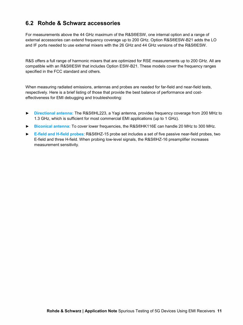
6.2 Rohde & Schwarz accessories
For measurements above the 44 GHz maximum of the R&S®ESW, one internal option and a range of external accessories can extend frequency coverage up to 200 GHz. Option R&S®ESW-B21 adds the LO and IF ports needed to use external mixers with the 26 GHz and 44 GHz versions of the R&S®ESW.
R&S offers a full range of harmonic mixers that are optimized for RSE measurements up to 200 GHz. All are compatible with an R&S®ESW that includes Option ESW-B21. These models cover the frequency ranges specified in the FCC standard and others.
When measuring radiated emissions, antennas and probes are needed for far-field and near-field tests, respectively. Here is a brief listing of those that provide the best balance of performance and cost-effectiveness for EMI debugging and troubleshooting:
► Directional antenna: The R&S®HL223, a Yagi antenna, provides frequency coverage from 200 MHz to 1.3 GHz, which is sufficient for most commercial EMI applications (up to 1 GHz).
► Biconical antenna: To cover lower frequencies, the R&S®HK116E can handle 20 MHz to 300 MHz.
► E-field and H-field probes: R&S®HZ-15 probe set includes a set of five passive near-field probes, two E-field and three H-field. When probing low-level signals, the R&S®HZ-16 preamplifier increases measurement sensitivity.

Rohde & Schwarz | Application Note Spurious Testing of 5G Devices Using EMI Receivers 12
7 Conclusion In pursuit of an impression vision, 5G is using two heavily regulated frequency bands. Equally important are the requirements around RSE testing of 5G UE and BS.
With multiple modes and a variety of useful capabilities, a modern, digitally-based EMI test receiver can help accelerate testing of spurious emissions from 5G designs. Thus, an R&S®ESW EMI test receiver with Option R&S®ESW-B21 and the necessary external mixers is an ideal solution for these essential measurements. Beyond the EMI test receiver mode, the R&S®ESW is also a versatile spectrum analyzer that includes real-time spectrum analysis, spectrogram displays, and standard-compliant TDS for faster assessment of RSE.
Because R&S personnel participate in the various responsible standards committees, our products are always current with the latest testing requirements. R&S is also the leader in providing fully compliant receivers and systems, and this expertise extends into competitively priced R&S instruments that can fit most budgets.

Rohde & Schwarz The Rohde & Schwarz electronics group offers innovative solutions in the following business fields: test and measurement, broadcast and media, secure communications, cybersecurity, monitoring and network testing. Founded more than 80 years ago, the independent company which is headquartered in Munich, Germany, has an extensive sales and service network with locations in more than 70 countries.
www.rohde-schwarz.com
Rohde & Schwarz training www.training.rohde-schwarz.com
Rohde & Schwarz customer support www.rohde-schwarz.com/support
Certified Quality Management
ISO 9001
PAD
-T-M
: 357
2.71
86.0
0/01
.00/
EN
R&S® is a registered trademark of Rohde & Schwarz GmbH & Co. KG Trade names are trademarks of the owners. Rohde & Schwarz | Version 1.00 | 08.2020 Application Note | Spurious Testing of 5G Devices Using EMI Receivers Data without tolerance limits is not binding | Subject to change © 2020 Rohde & Schwarz GmbH & Co. KG | 81671 Munich, Germany www.rohde-schwarz.com