Embed Size (px)
Citation preview
Application Note
W-LAN 802.11ac Measurement
MX269028A
Demonstration using Signal Analyzer and Vector Signal Generator
WLAN (802.11) Measurement Software
MX269028A-002 802.11ac (160 MHz) Measurement Software
MS2690A/MS2691A/MS2692A Signal Analyzer
MG3710A Vector Signal Generator
MX370111A WLAN IQproducer
MX370111A-002 802.11ac (160 MHz) Option

1 MX269028A/MX370111A-E-F-1-(1.00)
Introduction This application note explains the procedures for outputting an IEEE802.11ac signal from a vector signal generator and measuring the modulation accuracy and power using a signal analyzer. The IEEE802.11ac PHY layer features 256QAM multi-level modulation compared to the IEEE802.11n PHY layer as well as both 80 MHz and 160 MHz (option) bandwidths, plus expandability for up to 8 MIMO streams. This application note provides an understanding of the features of IEEE802.11ac through the following items: Generation and output of 256QAM, 80-MHz band signals and measurement of their Tx characteristics Generation and output of 256QAM, 160-MHz band signals and measurement of their Tx characteristics Generation and output of 8 x 8 MIMO signals and measurement of their Tx characteristics Sending of specified number of packets from vector signal generator (mainly for Rx tests)
2 MX269028A/MX370111A-E-F-1-(1.00)
Preparations The instruments, etc., required for this demonstration are listed below. MG3710A Vector Signal Generator (Version 2.01.00 or newer firmware and IQproducer Version 14.01 or
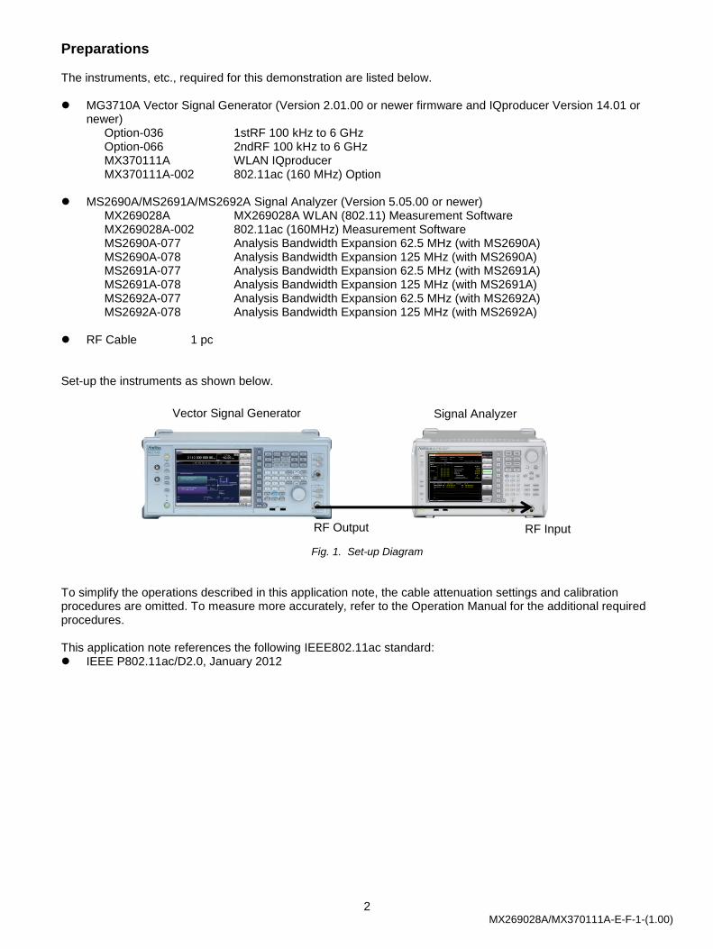
newer) Option-036 1stRF 100 kHz to 6 GHz Option-066 2ndRF 100 kHz to 6 GHz MX370111A WLAN IQproducer MX370111A-002 802.11ac (160 MHz) Option MS2690A/MS2691A/MS2692A Signal Analyzer (Version 5.05.00 or newer) MX269028A MX269028A WLAN (802.11) Measurement Software MX269028A-002 802.11ac (160MHz) Measurement Software MS2690A-077 Analysis Bandwidth Expansion 62.5 MHz (with MS2690A) MS2690A-078 Analysis Bandwidth Expansion 125 MHz (with MS2690A) MS2691A-077 Analysis Bandwidth Expansion 62.5 MHz (with MS2691A) MS2691A-078 Analysis Bandwidth Expansion 125 MHz (with MS2691A) MS2692A-077 Analysis Bandwidth Expansion 62.5 MHz (with MS2692A) MS2692A-078 Analysis Bandwidth Expansion 125 MHz (with MS2692A) RF Cable 1 pc Set-up the instruments as shown below.
Fig. 1. Set-up Diagram
To simplify the operations described in this application note, the cable attenuation settings and calibration procedures are omitted. To measure more accurately, refer to the Operation Manual for the additional required procedures. This application note references the following IEEE802.11ac standard: IEEE P802.11ac/D2.0, January 2012
RF Output
Vector Signal Generator Signal Analyzer
RF Input
3 MX269028A/MX370111A-E-F-1-(1.00)
Generating and Measuring 80-MHz Band Signals
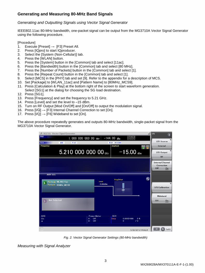
Generating and Outputting Signals using Vector Signal Generator IEEE802.11ac 80-MHz bandwidth, one-packet signal can be output from the MG3710A Vector Signal Generator using the following procedure. [Procedure] 1. Execute [Preset] → [F3] Preset All. 2. Press [IQpro] to start IQproducer. 3. Select the [System (Non-Cellular)] tab. 4. Press the [WLAN] button. 5. Press the [System] button in the [Common] tab and select [11ac]. 6. Press the [Bandwidth] button in the [Common] tab and select [80 MHz]. 7. Press the [Number of Packets] button in the [Common] tab and select [1]. 8. Press the [Repeat Count] button in the [Common] tab and select [1]. 9. Select [MCS] in the [PHY] tab and set [9]. Refer to the appendix for a description of MCS. 10. Set [Package] to [WLAN_11ac] and [Pattern Name] to [80MHz_MCS9]. 11. Press [Calculation & Play] at the bottom right of the screen to start waveform generation.
Select [SG1] at the dialog for choosing the SG load destination. 12. Press [SG1]. 13. Press [Frequency] and set the frequency to 5.21 GHz. 14. Press [Level] and set the level to –15 dBm. 15. Turn on RF Output [Mod On/Off] and [On/Off] to output the modulation signal. 16. Press [I/Q] → [F3] Internal Channel Correction to set [On]. 17. Press [I/Q] → [F6] Wideband to set [On]. The above procedure repeatedly generates and outputs 80-MHz bandwidth, single-packet signal from the MG3710A Vector Signal Generator.
Fig. 2. Vector Signal Generator Settings (80-MHz bandwidth)
Measuring with Signal Analyzer
4 MX269028A/MX370111A-E-F-1-(1.00)
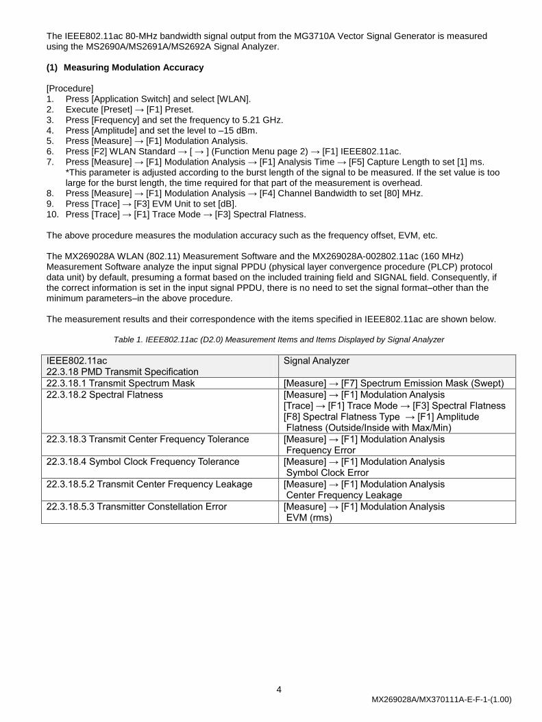
The IEEE802.11ac 80-MHz bandwidth signal output from the MG3710A Vector Signal Generator is measured using the MS2690A/MS2691A/MS2692A Signal Analyzer. (1) Measuring Modulation Accuracy [Procedure] 1. Press [Application Switch] and select [WLAN]. 2. Execute [Preset] → [F1] Preset. 3. Press [Frequency] and set the frequency to 5.21 GHz. 4. Press [Amplitude] and set the level to –15 dBm. 5. Press [Measure] → [F1] Modulation Analysis. 6. Press [F2] WLAN Standard → [ → ] (Function Menu page 2) → [F1] IEEE802.11ac. 7. Press [Measure] → [F1] Modulation Analysis → [F1] Analysis Time → [F5] Capture Length to set [1] ms.
*This parameter is adjusted according to the burst length of the signal to be measured. If the set value is too large for the burst length, the time required for that part of the measurement is overhead.
8. Press [Measure] → [F1] Modulation Analysis → [F4] Channel Bandwidth to set [80] MHz. 9. Press [Trace] → [F3] EVM Unit to set [dB]. 10. Press [Trace] → [F1] Trace Mode → [F3] Spectral Flatness. The above procedure measures the modulation accuracy such as the frequency offset, EVM, etc. The MX269028A WLAN (802.11) Measurement Software and the MX269028A-002802.11ac (160 MHz) Measurement Software analyze the input signal PPDU (physical layer convergence procedure (PLCP) protocol data unit) by default, presuming a format based on the included training field and SIGNAL field. Consequently, if the correct information is set in the input signal PPDU, there is no need to set the signal format–other than the minimum parameters–in the above procedure. The measurement results and their correspondence with the items specified in IEEE802.11ac are shown below.
Table 1. IEEE802.11ac (D2.0) Measurement Items and Items Displayed by Signal Analyzer
IEEE802.11ac 22.3.18 PMD Transmit Specification
Signal Analyzer
22.3.18.1 Transmit Spectrum Mask [Measure] → [F7] Spectrum Emission Mask (Swept)
22.3.18.2 Spectral Flatness [Measure] → [F1] Modulation Analysis [Trace] → [F1] Trace Mode → [F3] Spectral Flatness [F8] Spectral Flatness Type → [F1] Amplitude Flatness (Outside/Inside with Max/Min)
22.3.18.3 Transmit Center Frequency Tolerance [Measure] → [F1] Modulation Analysis Frequency Error
22.3.18.4 Symbol Clock Frequency Tolerance [Measure] → [F1] Modulation Analysis Symbol Clock Error
22.3.18.5.2 Transmit Center Frequency Leakage [Measure] → [F1] Modulation Analysis Center Frequency Leakage
22.3.18.5.3 Transmitter Constellation Error [Measure] → [F1] Modulation Analysis EVM (rms)
5 MX269028A/MX370111A-E-F-1-(1.00)
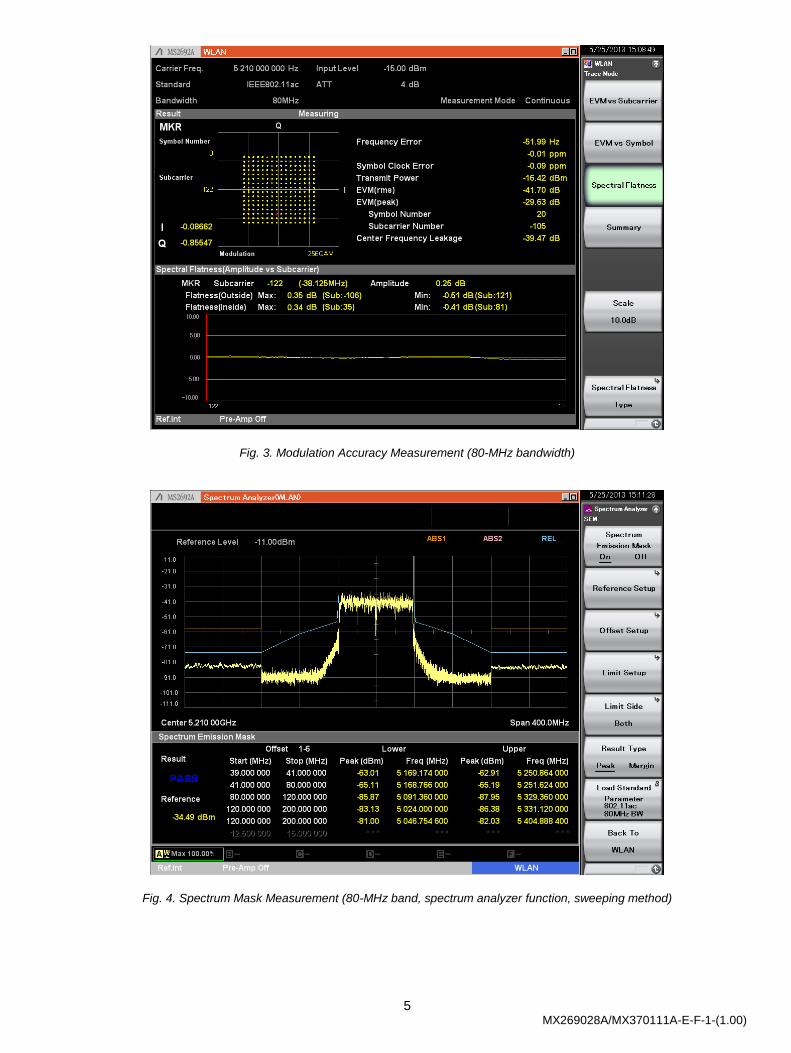
Fig. 3. Modulation Accuracy Measurement (80-MHz bandwidth)
Fig. 4. Spectrum Mask Measurement (80-MHz band, spectrum analyzer function, sweeping method)
6 MX269028A/MX370111A-E-F-1-(1.00)
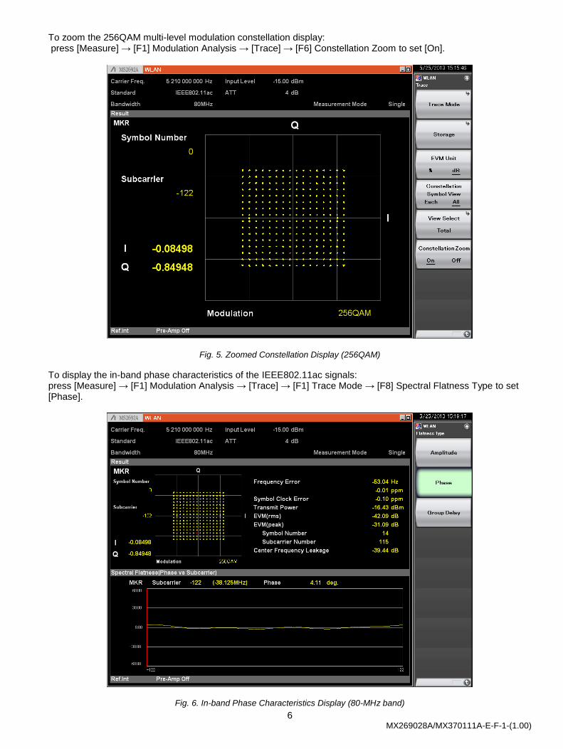
To zoom the 256QAM multi-level modulation constellation display: press [Measure] → [F1] Modulation Analysis → [Trace] → [F6] Constellation Zoom to set [On].
Fig. 5. Zoomed Constellation Display (256QAM)
To display the in-band phase characteristics of the IEEE802.11ac signals: press [Measure] → [F1] Modulation Analysis → [Trace] → [F1] Trace Mode → [F8] Spectral Flatness Type to set [Phase].
Fig. 6. In-band Phase Characteristics Display (80-MHz band)
7 MX269028A/MX370111A-E-F-1-(1.00)
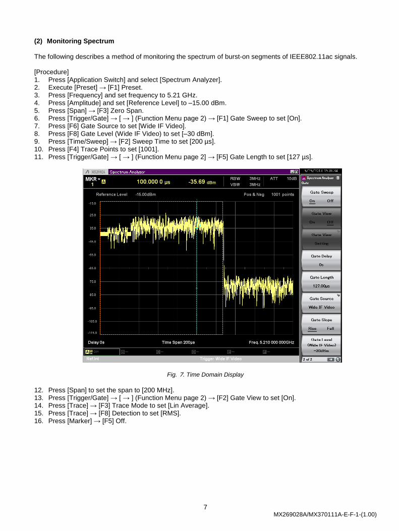
(2) Monitoring Spectrum The following describes a method of monitoring the spectrum of burst-on segments of IEEE802.11ac signals. [Procedure] 1. Press [Application Switch] and select [Spectrum Analyzer]. 2. Execute [Preset] → [F1] Preset. 3. Press [Frequency] and set frequency to 5.21 GHz. 4. Press [Amplitude] and set [Reference Level] to –15.00 dBm. 5. Press [Span] → [F3] Zero Span. 6. Press [Trigger/Gate] → [ → ] (Function Menu page 2) → [F1] Gate Sweep to set [On]. 7. Press [F6] Gate Source to set [Wide IF Video]. 8. Press [F8] Gate Level (Wide IF Video) to set [–30 dBm]. 9. Press [Time/Sweep] → [F2] Sweep Time to set [200 µs]. 10. Press [F4] Trace Points to set [1001]. 11. Press [Trigger/Gate] → [ → ] (Function Menu page 2] → [F5] Gate Length to set [127 µs].
Fig. 7. Time Domain Display
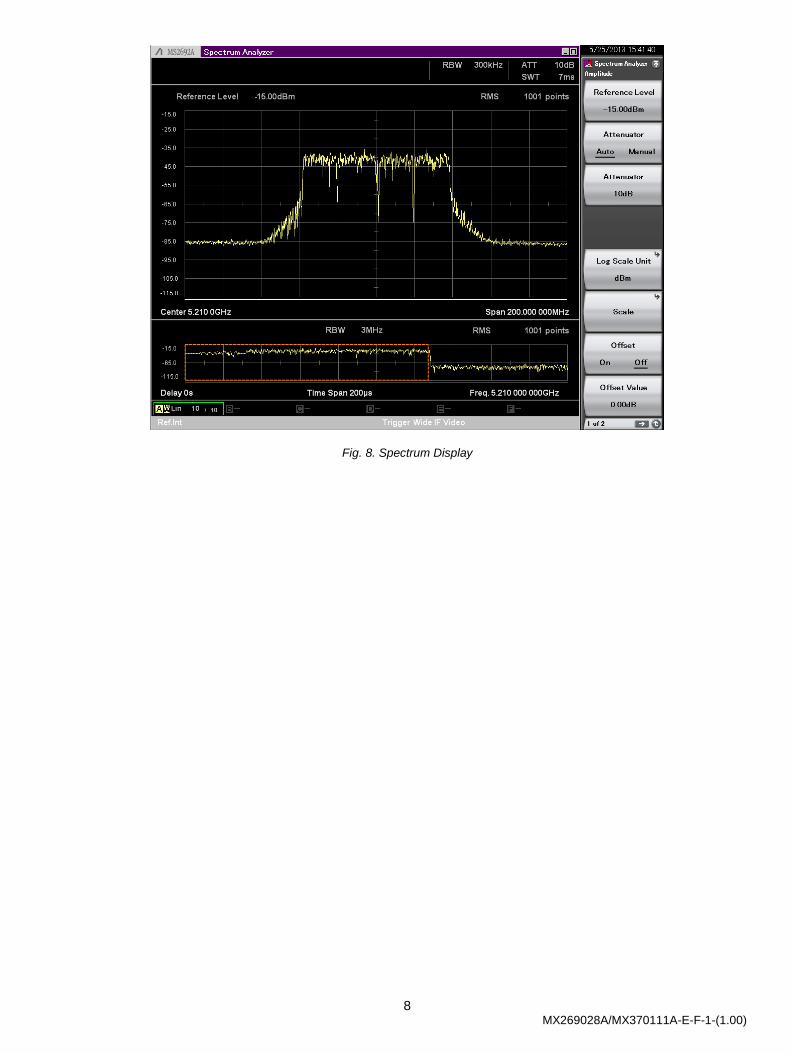
12. Press [Span] to set the span to [200 MHz]. 13. Press [Trigger/Gate] → [ → ] (Function Menu page 2) → [F2] Gate View to set [On]. 14. Press [Trace] → [F3] Trace Mode to set [Lin Average]. 15. Press [Trace] → [F8] Detection to set [RMS]. 16. Press [Marker] → [F5] Off.
8 MX269028A/MX370111A-E-F-1-(1.00)
Fig. 8. Spectrum Display
9 MX269028A/MX370111A-E-F-1-(1.00)
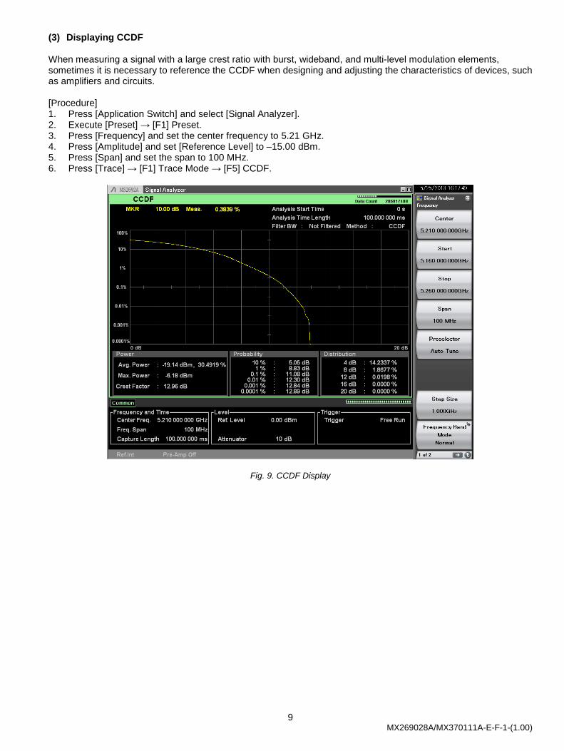
(3) Displaying CCDF When measuring a signal with a large crest ratio with burst, wideband, and multi-level modulation elements, sometimes it is necessary to reference the CCDF when designing and adjusting the characteristics of devices, such as amplifiers and circuits. [Procedure] 1. Press [Application Switch] and select [Signal Analyzer]. 2. Execute [Preset] → [F1] Preset. 3. Press [Frequency] and set the center frequency to 5.21 GHz. 4. Press [Amplitude] and set [Reference Level] to –15.00 dBm. 5. Press [Span] and set the span to 100 MHz. 6. Press [Trace] → [F1] Trace Mode → [F5] CCDF.
Fig. 9. CCDF Display

10 MX269028A/MX370111A-E-F-1-(1.00)
Generating and Measuring 160-MHz Bandwidth Signals
Generating and Outputting Signals with Vector Signal Generator IEEE802.11ac 160-MHz bandwidth signals can be output from the MG3710A Vector Signal Generator using the following procedure. [Procedure] 1. [Execute [Preset] → [F3] Preset All. 2. [Press [IQpro] to start IQproducer. 3. [Select the [System (Non-Cellular)] tab. 4. [Press the [WLAN] button. 5. Press the [System] button in the [Common] tab and select [11ac]. 6. Press the [Bandwidth] button in the [Common] tab and select [80 MHz]. 7. Press the [Number of Packets] button in the [Common] tab and select [1]. 8. Press the [Repeat Count] button in the [Common] tab and select [1]. 9. Select [MCS] in the [PHY] tab and set [9]. 10. Set [Package] to [WLAN_11ac] and [Pattern Name] to [160MHz_MCS9]. 11. Press [Calculation & Play] at the bottom right of the screen to start waveform generation.
Select [SG1] at the dialog for choosing the SG load destination. 12. Press [SG1]. 13. Press [Frequency] and set the frequency to 5.25 GHz. 14. Press [Level] and set the level to –15 dBm. 15. Turn on RF Output [Mod On/Off] and [On/Off] to output the modulation signal. 16. Press [I/Q] → [F3] Internal Channel Correction to set [On]. 17. Press [I/Q] → [F6] Wideband to set [On]. The above procedure repeatedly generates and outputs IEEE802.11ac 160-MHz bandwidth, single-packet signal from the MG3710A Vector Signal Generator.
Fig. 10. Vector Signal Generator Settings (160-MHz bandwidth)
11 MX269028A/MX370111A-E-F-1-(1.00)
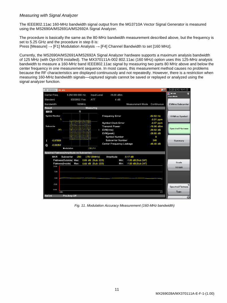
Measuring with Signal Analyzer The IEEE802.11ac 160-MHz bandwidth signal output from the MG3710A Vector Signal Generator is measured using the MS2690A/MS2691A/MS2692A Signal Analyzer. The procedure is basically the same as the 80-MHz bandwidth measurement described above, but the frequency is set to 5.25 GHz and the procedure in step 8 is: Press [Measure] → [F1] Modulation Analysis → [F4] Channel Bandwidth to set [160 MHz]. Currently, the MS2690A/MS2691A/MS2692A Signal Analyzer hardware supports a maximum analysis bandwidth of 125 MHz (with Opt-078 installed). The MX370111A-002 802.11ac (160 MHz) option uses this 125-MHz analysis bandwidth to measure a 160-MHz band IEEE802.11ac signal by measuring two parts 80 MHz above and below the center frequency in one measurement sequence. In most cases, this measurement method causes no problems because the RF characteristics are displayed continuously and not repeatedly. However, there is a restriction when measuring 160-MHz bandwidth signals—captured signals cannot be saved or replayed or analyzed using the signal analyzer function.
Fig. 11. Modulation Accuracy Measurement (160-MHz bandwidth)
12 MX269028A/MX370111A-E-F-1-(1.00)
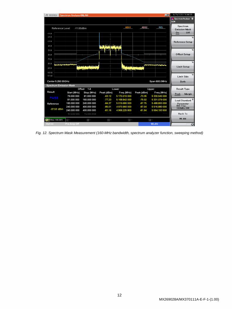
Fig. 12. Spectrum Mask Measurement (160-MHz bandwidth, spectrum analyzer function, sweeping method)

13 MX269028A/MX370111A-E-F-1-(1.00)
MIMO Signal Generation and Measurement The IQproducer MX370111A-002 802.11ac (160 MHz) option features the IEEE802.11ac standard supporting up to 8 transmit chains, as well as single-user and multi-user modes for 8 spatial streams. When measuring MIMO IEEE802.11ac signals using the MX269028A-002 802.11ac (160 MHz) measurement software, each antenna signal is measured separately. When using only a single MS2690A/MS2691A/MS2692A Signal Analyzer, measurement is performed by switching each antenna. Now, when measuring MIMO signals using the MX269028A-002 802.11ac (160 MHz) Measurement Software, it is necessary to use the single-user mode with direct mapping method as well as the number of channels and transmit chains. Eight antennas (Antenna 0 to Antenna 7) can be measured. The MX269028A-002 802.11ac (160 MHz) Measurement Software can analyze the power, modulation accuracy and spectrum characteristics at the transmitter test measurement points of the MIMO model shown below. It cannot analyze receiver test measurement point signals, meaning the mixed signals output from each antenna.
Fig. 13. MIMO Conceptual Model and Measurement Points
Fig. 14. MIMO Transmitter Test Setup
Transmitter Receiver
Transmitter Test Measurement Points
(using MS2690A/MS2691A/MS2692A
Signal Analyzer) Receiver Test Measurement Points
Transmitter
Antenna 0
Antenna 1
Antenna 2
Antenna N-1
14 MX269028A/MX370111A-E-F-1-(1.00)
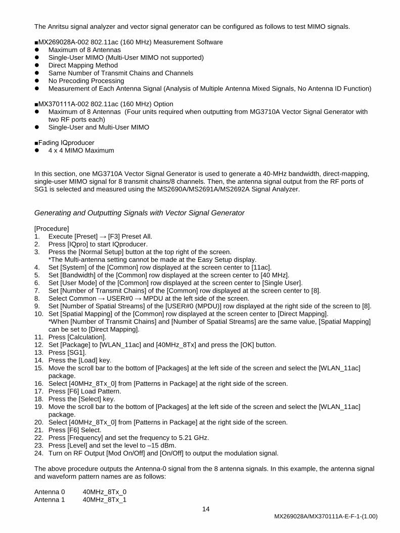
The Anritsu signal analyzer and vector signal generator can be configured as follows to test MIMO signals. ■MX269028A-002 802.11ac (160 MHz) Measurement Software Maximum of 8 Antennas Single-User MIMO (Multi-User MIMO not supported) Direct Mapping Method Same Number of Transmit Chains and Channels No Precoding Processing Measurement of Each Antenna Signal (Analysis of Multiple Antenna Mixed Signals, No Antenna ID Function) ■MX370111A-002 802.11ac (160 MHz) Option Maximum of 8 Antennas (Four units required when outputting from MG3710A Vector Signal Generator with
two RF ports each) Single-User and Multi-User MIMO ■Fading IQproducer 4 x 4 MIMO Maximum In this section, one MG3710A Vector Signal Generator is used to generate a 40-MHz bandwidth, direct-mapping, single-user MIMO signal for 8 transmit chains/8 channels. Then, the antenna signal output from the RF ports of SG1 is selected and measured using the MS2690A/MS2691A/MS2692A Signal Analyzer.
Generating and Outputting Signals with Vector Signal Generator [Procedure] 1. Execute [Preset] → [F3] Preset All. 2. Press [IQpro] to start IQproducer. 3. Press the [Normal Setup] button at the top right of the screen.
*The Multi-antenna setting cannot be made at the Easy Setup display. 4. Set [System] of the [Common] row displayed at the screen center to [11ac]. 5. Set [Bandwidth] of the [Common] row displayed at the screen center to [40 MHz]. 6. Set [User Mode] of the [Common] row displayed at the screen center to [Single User]. 7. Set [Number of Transmit Chains] of the [Common] row displayed at the screen center to [8]. 8. Select Common → USER#0 → MPDU at the left side of the screen. 9. Set [Number of Spatial Streams] of the [USER#0 (MPDU)] row displayed at the right side of the screen to [8]. 10. Set [Spatial Mapping] of the [Common] row displayed at the screen center to [Direct Mapping].
*When [Number of Transmit Chains] and [Number of Spatial Streams] are the same value, [Spatial Mapping] can be set to [Direct Mapping].
11. Press [Calculation]. 12. Set [Package] to [WLAN_11ac] and [40MHz_8Tx] and press the [OK] button. 13. Press [SG1]. 14. Press the [Load] key. 15. Move the scroll bar to the bottom of [Packages] at the left side of the screen and select the [WLAN_11ac]
package. 16. Select [40MHz_8Tx_0] from [Patterns in Package] at the right side of the screen. 17. Press [F6] Load Pattern. 18. Press the [Select] key. 19. Move the scroll bar to the bottom of [Packages] at the left side of the screen and select the [WLAN_11ac]
package. 20. Select [40MHz_8Tx_0] from [Patterns in Package] at the right side of the screen. 21. Press [F6] Select. 22. Press [Frequency] and set the frequency to 5.21 GHz. 23. Press [Level] and set the level to –15 dBm. 24. Turn on RF Output [Mod On/Off] and [On/Off] to output the modulation signal. The above procedure outputs the Antenna-0 signal from the 8 antenna signals. In this example, the antenna signal and waveform pattern names are as follows: Antenna 0 40MHz_8Tx_0 Antenna 1 40MHz_8Tx_1
15 MX269028A/MX370111A-E-F-1-(1.00)
・・・ Antenna 7 40MHz_8Tx_7
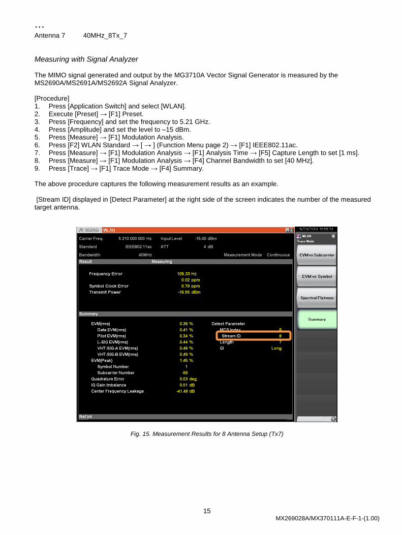
Measuring with Signal Analyzer The MIMO signal generated and output by the MG3710A Vector Signal Generator is measured by the MS2690A/MS2691A/MS2692A Signal Analyzer. [Procedure] 1. Press [Application Switch] and select [WLAN]. 2. Execute [Preset] → [F1] Preset. 3. Press [Frequency] and set the frequency to 5.21 GHz. 4. Press [Amplitude] and set the level to –15 dBm. 5. Press [Measure] → [F1] Modulation Analysis. 6. Press [F2] WLAN Standard → [ → ] (Function Menu page 2) → [F1] IEEE802.11ac. 7. Press [Measure] → [F1] Modulation Analysis → [F1] Analysis Time → [F5] Capture Length to set [1 ms]. 8. Press [Measure] → [F1] Modulation Analysis → [F4] Channel Bandwidth to set [40 MHz]. 9. Press [Trace] → [F1] Trace Mode → [F4] Summary. The above procedure captures the following measurement results as an example. [Stream ID] displayed in [Detect Parameter] at the right side of the screen indicates the number of the measured target antenna.
Fig. 15. Measurement Results for 8 Antenna Setup (Tx7)
16 MX269028A/MX370111A-E-F-1-(1.00)
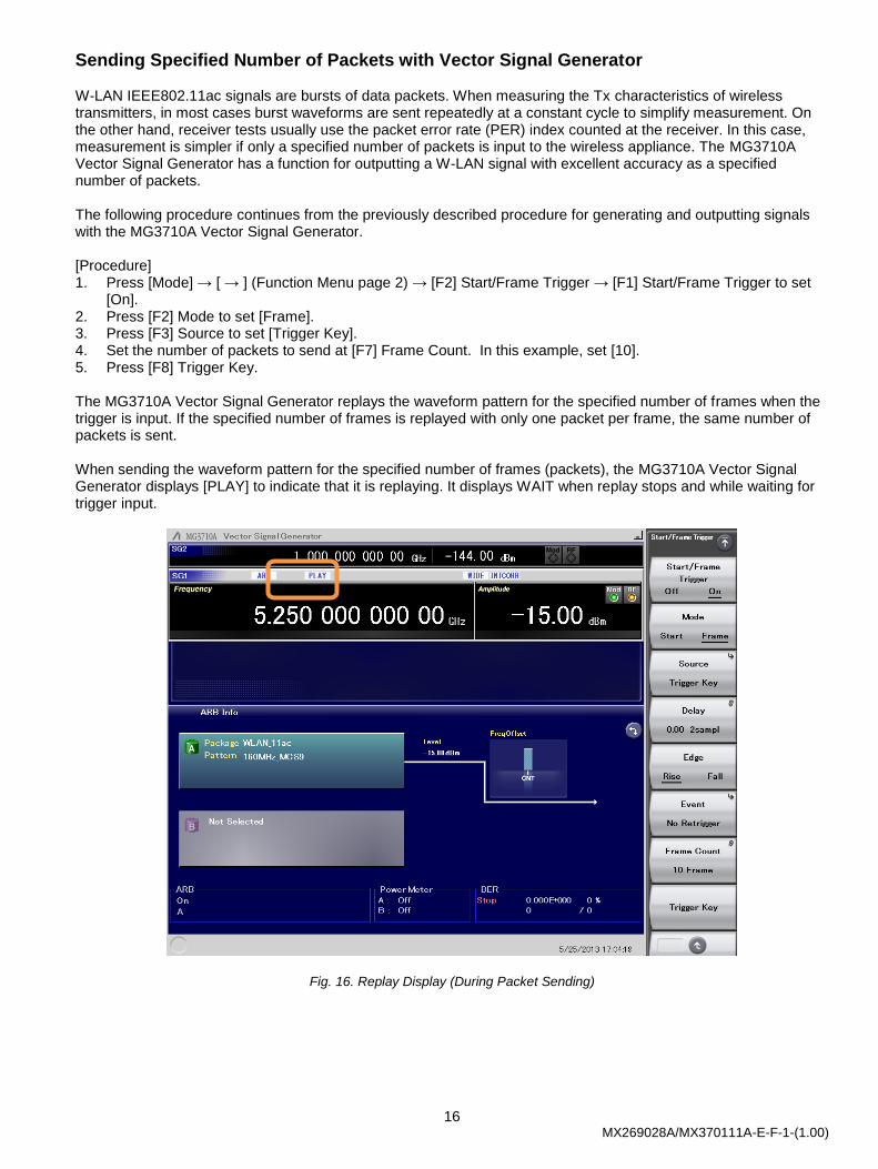
Sending Specified Number of Packets with Vector Signal Generator W-LAN IEEE802.11ac signals are bursts of data packets. When measuring the Tx characteristics of wireless transmitters, in most cases burst waveforms are sent repeatedly at a constant cycle to simplify measurement. On the other hand, receiver tests usually use the packet error rate (PER) index counted at the receiver. In this case, measurement is simpler if only a specified number of packets is input to the wireless appliance. The MG3710A Vector Signal Generator has a function for outputting a W-LAN signal with excellent accuracy as a specified number of packets. The following procedure continues from the previously described procedure for generating and outputting signals with the MG3710A Vector Signal Generator. [Procedure] 1. Press [Mode] → [ → ] (Function Menu page 2) → [F2] Start/Frame Trigger → [F1] Start/Frame Trigger to set
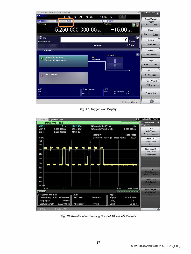
[On]. 2. Press [F2] Mode to set [Frame]. 3. Press [F3] Source to set [Trigger Key]. 4. Set the number of packets to send at [F7] Frame Count. In this example, set [10]. 5. Press [F8] Trigger Key. The MG3710A Vector Signal Generator replays the waveform pattern for the specified number of frames when the trigger is input. If the specified number of frames is replayed with only one packet per frame, the same number of packets is sent. When sending the waveform pattern for the specified number of frames (packets), the MG3710A Vector Signal Generator displays [PLAY] to indicate that it is replaying. It displays WAIT when replay stops and while waiting for trigger input.
Fig. 16. Replay Display (During Packet Sending)
17 MX269028A/MX370111A-E-F-1-(1.00)
Fig. 17. Trigger Wait Display
Fig. 18. Results when Sending Burst of 10 W-LAN Packets
18 MX269028A/MX370111A-E-F-1-(1.00)
Appendix
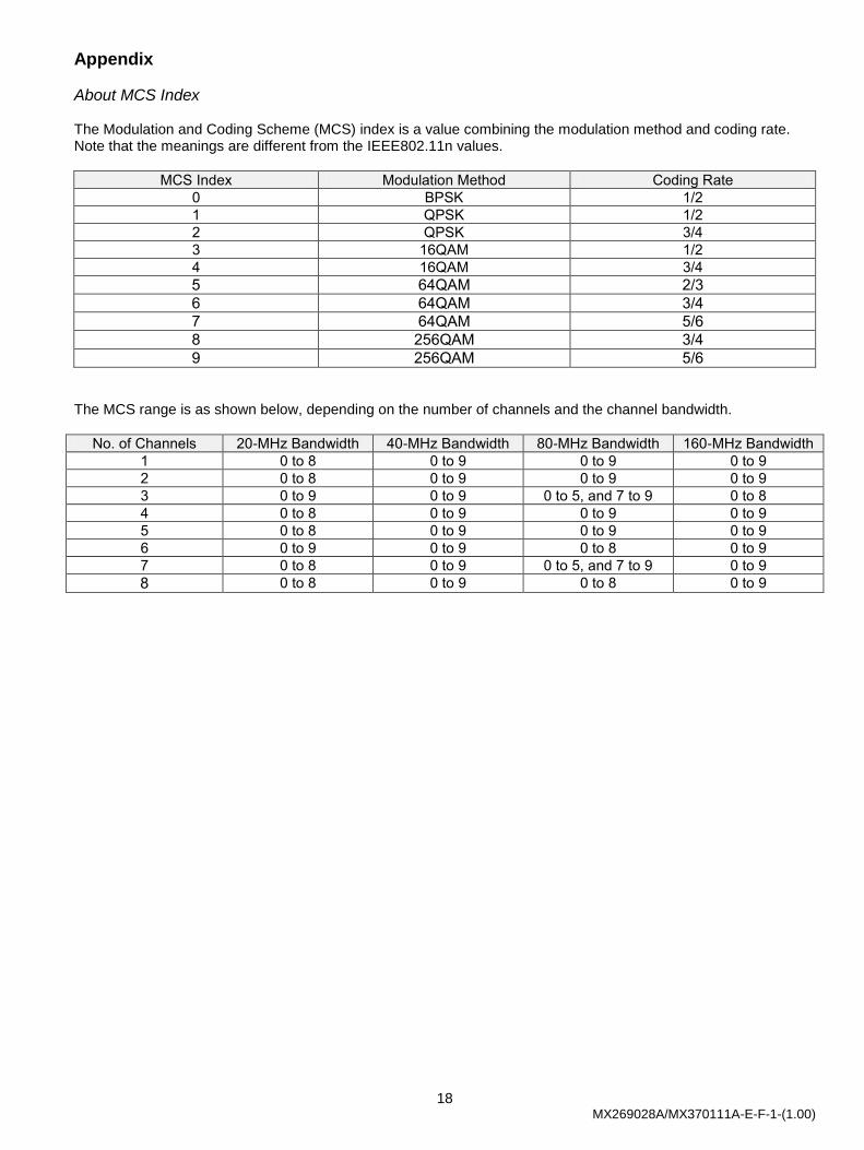
About MCS Index The Modulation and Coding Scheme (MCS) index is a value combining the modulation method and coding rate. Note that the meanings are different from the IEEE802.11n values.
MCS Index Modulation Method Coding Rate
0 BPSK 1/2
1 QPSK 1/2
2 QPSK 3/4
3 16QAM 1/2
4 16QAM 3/4
5 64QAM 2/3
6 64QAM 3/4
7 64QAM 5/6
8 256QAM 3/4
9 256QAM 5/6 The MCS range is as shown below, depending on the number of channels and the channel bandwidth.
No. of Channels 20-MHz Bandwidth 40-MHz Bandwidth 80-MHz Bandwidth 160-MHz Bandwidth
1 0 to 8 0 to 9 0 to 9 0 to 9
2 0 to 8 0 to 9 0 to 9 0 to 9
3 0 to 9 0 to 9 0 to 5, and 7 to 9 0 to 8
4 0 to 8 0 to 9 0 to 9 0 to 9
5 0 to 8 0 to 9 0 to 9 0 to 9
6 0 to 9 0 to 9 0 to 8 0 to 9
7 0 to 8 0 to 9 0 to 5, and 7 to 9 0 to 9
8 0 to 8 0 to 9 0 to 8 0 to 9
• United StatesAnritsu Company1155 East Collins Blvd., Suite 100, Richardson, TX 75081, U.S.A.Toll Free: 1-800-267-4878Phone: +1-972-644-1777Fax: +1-972-671-1877
• CanadaAnritsu Electronics Ltd.700 Silver Seven Road, Suite 120, Kanata, Ontario K2V 1C3, CanadaPhone: +1-613-591-2003 Fax: +1-613-591-1006
• BrazilAnritsu Eletrônica Ltda.Praça Amadeu Amaral, 27 - 1 Andar01327-010 - Bela Vista - São Paulo - SP - BrazilPhone: +55-11-3283-2511Fax: +55-11-3288-6940
• MexicoAnritsu Company, S.A. de C.V.Av. Ejército Nacional No. 579 Piso 9, Col. Granada11520 México, D.F., MéxicoPhone: +52-55-1101-2370Fax: +52-55-5254-3147
• United KingdomAnritsu EMEA Ltd.200 Capability Green, Luton, Bedfordshire, LU1 3LU, U.K.Phone: +44-1582-433200 Fax: +44-1582-731303
• FranceAnritsu S.A.12 avenue du Québec, Bâtiment Iris 1- Silic 612,91140 VILLEBON SUR YVETTE, FrancePhone: +33-1-60-92-15-50Fax: +33-1-64-46-10-65
• GermanyAnritsu GmbHNemetschek Haus, Konrad-Zuse-Platz 1 81829 München, Germany Phone: +49-89-442308-0 Fax: +49-89-442308-55
• ItalyAnritsu S.r.l.Via Elio Vittorini 129, 00144 Roma, ItalyPhone: +39-6-509-9711 Fax: +39-6-502-2425
• SwedenAnritsu ABBorgarfjordsgatan 13A, 164 40 KISTA, SwedenPhone: +46-8-534-707-00 Fax: +46-8-534-707-30
• FinlandAnritsu ABTeknobulevardi 3-5, FI-01530 VANTAA, FinlandPhone: +358-20-741-8100Fax: +358-20-741-8111
• DenmarkAnritsu A/S (Service Assurance)Anritsu AB (Test & Measurement)Kay Fiskers Plads 9, 2300 Copenhagen S, DenmarkPhone: +45-7211-2200Fax: +45-7211-2210
• RussiaAnritsu EMEA Ltd. Representation Office in RussiaTverskaya str. 16/2, bld. 1, 7th floor.Russia, 125009, MoscowPhone: +7-495-363-1694Fax: +7-495-935-8962
• United Arab EmiratesAnritsu EMEA Ltd.Dubai Liaison OfficeP O Box 500413 - Dubai Internet CityAl Thuraya Building, Tower 1, Suit 701, 7th FloorDubai, United Arab EmiratesPhone: +971-4-3670352Fax: +971-4-3688460
• IndiaAnritsu India Private Limited2nd & 3rd Floor, #837/1, Binnamangla 1st Stage, Indiranagar, 100ft Road, Bangalore - 560038, IndiaPhone: +91-80-4058-1300Fax: +91-80-4058-1301
• SingaporeAnritsu Pte. Ltd.60 Alexandra Terrace, #02-08, The Comtech (Lobby A)Singapore 118502Phone: +65-6282-2400Fax: +65-6282-2533
• P.R. China (Shanghai)Anritsu (China) Co., Ltd.Room 2701-2705, Tower A, New Caohejing International Business CenterNo. 391 Gui Ping Road Shanghai, 200233, P.R. ChinaPhone: +86-21-6237-0898Fax: +86-21-6237-0899
• P.R. China (Hong Kong)Anritsu Company Ltd.Unit 1006-7, 10/F., Greenfield Tower, Concordia Plaza,No. 1 Science Museum Road, Tsim Sha Tsui East, Kowloon, Hong Kong, P.R. ChinaPhone: +852-2301-4980Fax: +852-2301-3545
• JapanAnritsu Corporation8-5, Tamura-cho, Atsugi-shi, Kanagawa, 243-0016 JapanPhone: +81-46-296-1221Fax: +81-46-296-1238
• KoreaAnritsu Corporation, Ltd.502, 5FL H-Square N B/D, 681Sampyeong-dong, Bundang-gu, Seongnam-si, Gyeonggi-do, 463-400 KoreaPhone: +82-31-696-7750Fax: +82-31-696-7751
• AustraliaAnritsu Pty. Ltd.Unit 21/270 Ferntree Gully Road, Notting Hill, Victoria 3168, AustraliaPhone: +61-3-9558-8177Fax: +61-3-9558-8255
• TaiwanAnritsu Company Inc.7F, No. 316, Sec. 1, NeiHu Rd., Taipei 114, TaiwanPhone: +886-2-8751-1816Fax: +886-2-8751-1817
Specifications are subject to change without notice.
1306
Printed on Recycled Paper
Please Contact:
No. MX269028A/MX370111A-E-F-1-(1.00) Printed in Japan 2013-6 MG