Embed Size (px)
Citation preview

802.11ac Wi-Fi Fundamentals Eric Johnson March 2014

CONFIDENTIAL © Copyright 2014. Aruba Networks, Inc. All rights reserved
2 #AirheadsConf
Agenda
11ac Standards Physical Layer Overview 11ac Data Rates Radio Realities
Transmitters Receivers
Antennas 11ac Beamforming 11ac Products

3 CONFIDENTIAL © Copyright 2014. Aruba Networks, Inc. All rights reserved
#AirheadsConf
802.11ac Technology Overview
Think of 11ac as an extension of 11n
• 11n specification introduced/leveraged: • 2.4 and 5 GHz supported • Wider channels (40 MHz) • Better modulation (64-
QAM) • Additional streams (up to 4
streams) • Beam forming (explicit and
implicit) • Backwards compatibility
with 11a/b/g
11ac introduces • 5 GHz supported • Even wider channels (80 MHz and 160 MHz)
• Be?er modulaAon (256-‐QAM) • AddiAonal streams (up to 8) • Beam forming (explicit) • Backwards compaAbility with 11a/b/g/n
• Refer to h?p://www.802-‐11.ac.net for in-‐depth informaAon

4 CONFIDENTIAL © Copyright 2014. Aruba Networks, Inc. All rights reserved
#AirheadsConf
Wider Channels
• 80 MHz channel widths supported in first generation – 80 MHz is 4.5x faster than 20 MHz – 80 MHz is contiguous – Per packet dynamic channel width decisions
• Future releases will allow for 160 MHz channel widths – 160 MHz can be either contiguous or in two non-
contiguous 80 MHz slices

5 CONFIDENTIAL © Copyright 2014. Aruba Networks, Inc. All rights reserved
#AirheadsConf
802.11ac Channels (FCC)
Channel
Freq (MHz)
UNII I and UNII II 2x 80 MHz 4x 40 MHz 8x 20 MHz
Band Edge Channel
Freq (MHz) 5850
US UNII III 1x 80 MHz 2x 40 MHz 5x 20 MHz
Channel
Freq (MHz)
UNII II extended 3x 80 MHz 6x 40 MHz 12x 20 MHz
36 48 44 52 40 56 64 60 Band Edge
5180 5200 5220 5240 5260 5280 5300 5320 5350
Band Edge 5150
149 161 157 153
5745 5765 5785 5805
Band Edge
5725
165
5825
100 112 108 116 104 120 128 124
5500 5520 5540 5560 5580 5600 5620 5640
Band Edge 5470
136 140 Band Edge
5680 5700 5725
132
5660
144
5720
Weather Radar

6 CONFIDENTIAL © Copyright 2014. Aruba Networks, Inc. All rights reserved
#AirheadsConf
802.11ac Channels (ETSI)
Channel
Freq (MHz)
UNII I and UNII II 2x 80 MHz 4x 40 MHz 8x 20 MHz
Channel
Freq (MHz)
UNII II extended 2x 80 MHz 5x 40 MHz 11x 20 MHz
36 48 44 52 40 56 64 60 Band Edge
5180 5200 5220 5240 5260 5280 5300 5320 5350
Band Edge 5150
100 112 108 116 104 120 128 124
5500 5520 5540 5560 5580 5600 5620 5640
Band Edge 5470
136 140 Band Edge
5680 5700 5725
132
5660

7 CONFIDENTIAL © Copyright 2014. Aruba Networks, Inc. All rights reserved
#AirheadsConf
Understanding 11ac Data Rates

8 CONFIDENTIAL © Copyright 2014. Aruba Networks, Inc. All rights reserved
#AirheadsConf
Terminology
• Symbol: basic element containing 1 to 8 bits of information
• Tone/Sub-Carriers: OFDM is made up of many tones. Each symbol is mapped to a tone.
• Cyclic Extension: technique used in OFDM to protect against multipath interference – You need cyclic extension but it is dead air and consumes transmit time
• Guard Band: Space between channels. In these regions tones have a constant value of zero amplitude
• Pilot Tones: Used to train the receiver and estimate the channel
• Radio Channel: For Wi-Fi 20, 40, 80, or 160 MHz of spectrum
• Propagation Channel: everything that happens between the transmitter and receiver
• FEC: Forward Error Correction. Redundant information that is sent to assist the receiver in decoding the bits.

9 CONFIDENTIAL © Copyright 2014. Aruba Networks, Inc. All rights reserved
#AirheadsConf
Sub-carriers
52 subcarriers (48 usable) for a 20 MHz non-HT mode (legacy 802.11a/g) channel
fc +10MHz -10MHz
26 carriers 26 carriers
56 subcarriers (52 usable) for a 20 MHz HT mode (802.11n) channel
fc
28 carriers 28 carriers
114 subcarriers (108 usable) for a 40 MHz HT mode (802.11n) channel
fc +10MHz -20MHz
57 carriers 57 carriers
+20MHz -10MHz
242 subcarriers (234 usable) for a 80 MHz VHT mode (802.11ac) channel An 80+80MHz or 16MHz channel is exactly two 80MHz channels, for 484 subcarriers (468 usable)
121 carriers 121 carriers
fc +10MHz -20MHz +20MHz -10MHz -40MHz -30MHz +30MHz +40MHz
OFDM subcarriers used in 802.11a, 802.11n and 802.11ac
+10MHz -10MHz
Guard Tones

10 CONFIDENTIAL © Copyright 2014. Aruba Networks, Inc. All rights reserved
#AirheadsConf
QAM constellations
Amplitude +1
Amplitude -1
Qua
drat
ure
-1
Quadrature +1
Amplitude +1
Amplitude -1 Q
uadr
atur
e -
1 Q
uadrature +1
Amplitude +1
Amplitude -1
Qua
drat
ure
-1
Quadrature +1
16-QAM constellation 64-QAM constellation 256-QAM constellation
Constellation diagrams for 16-, 64-, 256-QAM

11 CONFIDENTIAL © Copyright 2014. Aruba Networks, Inc. All rights reserved
#AirheadsConf
How do I get to the data rate for a given MCS?
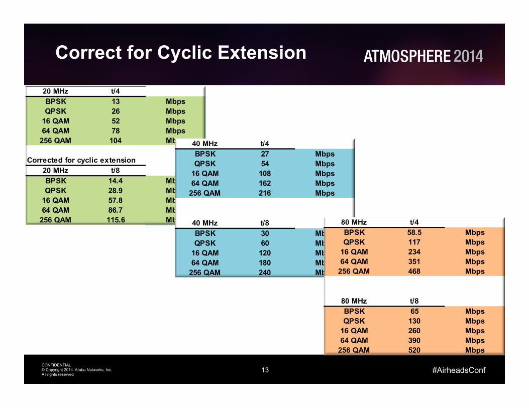
• Basic Symbol Rate – 312.5 KHz – 3.2 µs
• Cyclic Extension – t/4 0.8 µs – t/8 0.4 µs
• Bits Per Tone – BPSK 1 – QPSK 2 – 16 QAM 4 – 64 QAM 6 – 256 QAM 8
11

12 CONFIDENTIAL © Copyright 2014. Aruba Networks, Inc. All rights reserved
#AirheadsConf
Raw Data Rates
• #Tones * Bits per Tone * Symbol Rate – 16 QAM, 20 MHz – 52 * 4 * 0.3125 = 65 Mbps
12
13 CONFIDENTIAL © Copyright 2014. Aruba Networks, Inc. All rights reserved
#AirheadsConf
Correct for Cyclic Extension
13

14 CONFIDENTIAL © Copyright 2014. Aruba Networks, Inc. All rights reserved
#AirheadsConf
Apply FEC Coding
14

15 CONFIDENTIAL © Copyright 2014. Aruba Networks, Inc. All rights reserved
#AirheadsConf
Transmitters

16 CONFIDENTIAL © Copyright 2014. Aruba Networks, Inc. All rights reserved
#AirheadsConf
Transmitter Line Up
16
DAC Symbol Generation
Up Convert PA

17 CONFIDENTIAL © Copyright 2014. Aruba Networks, Inc. All rights reserved
#AirheadsConf
Transmitter Terms
• Conducted Power – This is the power that leaves the connectors
• EIRP: Effective Isotropic Radiated Power – This is the conducted power (dBm) + antenna gain (dBi) in
the direction of interest – cable losses (dB)
• Peak EIRP – This is what is regulated – It is the conducted power + peak gain – cable losses
• dBm: log power ratio to milliwatt • dBi: antenna gain relative to isotropic • dBr: relative power eg:used with describing
transmit mask
17
18 CONFIDENTIAL © Copyright 2014. Aruba Networks, Inc. All rights reserved
#AirheadsConf
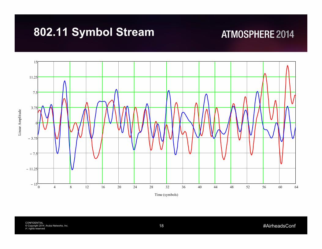
802.11 Symbol Stream
18
0 4 8 12 16 20 24 28 32 36 40 44 48 52 56 60 6415−
11.25−
7.5−
3.75−
0
3.75
7.5
11.25
15
Time (symbols)
Line
ar A
mpl
itude

19 CONFIDENTIAL © Copyright 2014. Aruba Networks, Inc. All rights reserved
#AirheadsConf
802.11n Signal Frequency Domain
19
0 5 10 15 20 25 30 35 4060−
50−
40−
30−
20−
10−
0
Frequency (MHz)
Am
plitu
de (d
B)
Digital Domain
After DAC
PA Non Linearity
0 5 10 15 20 25 30 35 4060−
50−
40−
30−
20−
10−
0
a

20 CONFIDENTIAL © Copyright 2014. Aruba Networks, Inc. All rights reserved
#AirheadsConf
Transmitter Non-Idealities
• DAC Quantization: this is due to the limited number of bits in a practical Digital to Analog Converter – This noise source is not affected when the power is reduced
• PA Non Linearity: OFDM has a high Peak to Average Ratio. The peaks in the OFDM signal cause distortions which manifest as noise like shoulders – Known as spectral regrowth – For every one 1 dB drop in tx power the regrowth drops by 3 dB
• 2 dB net
• The in channel noise is referred to as EVM – Error Vector Magnitude
• The out of channel noise interferes with other Wi-Fi channels and determines how close we can space antennas
20

21 CONFIDENTIAL © Copyright 2014. Aruba Networks, Inc. All rights reserved
#AirheadsConf
EVM
• As the depth of modulation increase the number of bits per symbol increases
• The in-band noise introduces uncertainty wrt to the actual symbol position
• Higher order modulations decrease the space between code points
• To make higher order modulations work the tx power needs to be reduced
• The EVM noise will add with interference and background noise
21
16 QAM

22 CONFIDENTIAL © Copyright 2014. Aruba Networks, Inc. All rights reserved
#AirheadsConf
BPSK 1/2 -‐5 -‐5QPSK 1/2 -‐10 -‐10QPSK 3/4 -‐13 -‐1316QAM 1/2 -‐16 -‐1616QAM 3/4 -‐19 -‐1964QAM 2/3 -‐22 -‐2264QAM 3/4 -‐25 -‐2564QAM 5/6 -‐28 -‐27256QAM 3/4 N/A -‐30256QAM 5/6 N/A -‐32
802.11n EVM (dB)
802.11ac EVM (dB)
Modulation Coding Rate
EVM Specfication and 22x tx table
22

23 CONFIDENTIAL © Copyright 2014. Aruba Networks, Inc. All rights reserved
#AirheadsConf
Receivers

24 CONFIDENTIAL © Copyright 2014. Aruba Networks, Inc. All rights reserved
#AirheadsConf
Receiver Line Up
24
ADC Symbol Decode
Down Convert LNA

25 CONFIDENTIAL © Copyright 2014. Aruba Networks, Inc. All rights reserved
#AirheadsConf
Receiver Impairments
• Analog Compression – Modern LNAs have very effective input power tolerance
• Digital Compression – This is where a high power signal hits the Automatic Gain
Control (AGC) Circuit. Gain drops and receiver sensitivity degrades
– The radio can be totally blocked if the power hits the Analog to Digital Converter (ADC) and consumes all the bits
• Intermodulation – Again, the effective linearity of modern LNAs reduces the
impact of this
25

26 CONFIDENTIAL © Copyright 2014. Aruba Networks, Inc. All rights reserved
#AirheadsConf
DAS Interference: Example
• Without filtering any signal that hits the receiver above -45 dBm will cause a reduction of sensitivity
• The degradation continues until about -15 dBm at which point the signal is totally blocked
• With a 100 mW (20 dBm) DAS system at 2100 MHz – Tx 20 dBm – Effective rx antenna gain 3 dBi – 1st meter at 2100 MHz -39 dB
• Power at 1m -19 dBm
– No impact distance 40 meters
26

27 CONFIDENTIAL © Copyright 2014. Aruba Networks, Inc. All rights reserved
#AirheadsConf
Advanced Cellular Coexistence
• Proliferation of DAS and new LTE bands at 2.6 GHz are creating issue for Wi-Fi solution
• All new APs introduced by Aruba in the last 12 months and going forward have implemented significant filtering into the 2.4 GHz radio portion to combat this
• Design solution – Use high-linear LNA followed with a high-rejection filter to achieve
rejection target and little sensitivity degradation; – Design target: Minimal Sensitivity degradation with -10dBm interference
from 3G/4G networks (theoretical analysis).

28 CONFIDENTIAL © Copyright 2014. Aruba Networks, Inc. All rights reserved
#AirheadsConf
Coverage Example
1. Sample coverage for 3x3 11n AP (or 3x3 11ac AP with 11n clients) in HT40 mode
• Coverage area sustains MCS5 and up
360 405
450

29 CONFIDENTIAL © Copyright 2014. Aruba Networks, Inc. All rights reserved
#AirheadsConf
Coverage Example
2. Upgrade to 3x3 11ac AP with 11ac clients, still using 40Mhz channels (VHT40)
• Radius for 600Mbps (MCS9) area is 1/4 of that for 450Mbps (MCS7)
360 405
450 540
600

30 CONFIDENTIAL © Copyright 2014. Aruba Networks, Inc. All rights reserved
#AirheadsConf
Coverage Example
3. Equivalent range for clients using 80MHz channels (VHT80)
– Rates roughly double, relative range for each of the MCS rates does not change, but 80MHz range is ~70% of equivalent (same MCS) 40MHz range
780 878 975 1170 1300
585

31 CONFIDENTIAL © Copyright 2014. Aruba Networks, Inc. All rights reserved
#AirheadsConf
Relative Range 802.11ac Rates
Datarate 40MHz 80MHz
MCS0 45 97.5 MCS1 90 195 MCS2 135 292.5 MCS3 180 390 MCS4 270 585 MCS5 360 780 MCS6 405 877.5 MCS7 450 975 MCS8 540 1,170 MCS9 600 1,300
Signal level and rela@ve range -‐dB r
MCS0 87 63 MCS1 85 50 MCS2 83 40 MCS3 79 25 MCS4 76 18 MCS5 71 10 MCS6 66 5.6 MCS7 63 4.0 MCS8 58 2.2 MCS9 51 1.0

32 CONFIDENTIAL © Copyright 2014. Aruba Networks, Inc. All rights reserved
#AirheadsConf
Pros and Cons of 802.11ac
• Pros 1. APs can accommodate more users/devices
• Increased capacity 2. Standards based Explicit Beam-forming increases SNR
• Higher data rates over longer distances 3. 256-QAM
• Increased throughput at high SNRs • Improved modulation and coding techniques
4. Multi-User MIMO (future generations) • Improved utilization of RF capacity
5. Use of 5 GHz spectrum • More non-overlapping channels • Quieter RF environment
33 CONFIDENTIAL © Copyright 2014. Aruba Networks, Inc. All rights reserved
#AirheadsConf
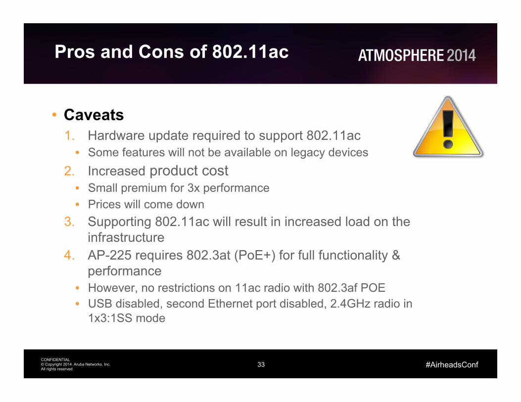
Pros and Cons of 802.11ac
• Caveats 1. Hardware update required to support 802.11ac
• Some features will not be available on legacy devices 2. Increased product cost
• Small premium for 3x performance • Prices will come down
3. Supporting 802.11ac will result in increased load on the infrastructure
4. AP-225 requires 802.3at (PoE+) for full functionality & performance
• However, no restrictions on 11ac radio with 802.3af POE • USB disabled, second Ethernet port disabled, 2.4GHz radio in
1x3:1SS mode

34 CONFIDENTIAL © Copyright 2014. Aruba Networks, Inc. All rights reserved
#AirheadsConf
Wave 2 of 11ac
• What will wave 2 802.11ac deliver? • MU-MIMO
• Use AP MIMO resources more effectively • Transmit data to multiple devices simultaneously: for example 4SS AP streaming
data to four 1SS clients simultaneously • 4x4:4SS
• Benefit of additional stream mostly for MU-MIMO • Not anticipating any 4x4:4SS client devices • Adds 33% to max datarate
• VHT160 • Doubles max datarate • Practical problem: only 2 VHT160 channels available in entire 5GHz band
• Max 5GHz radio throughput triples again! • 450 (11n 3x3 HT40), 1,300 (11ac 3x3 VHT80), 3,467 (11ac 4x4 VHT160)
• When will it be available? • Radio chipsets available late 2014 • Products in 2015

35 CONFIDENTIAL © Copyright 2014. Aruba Networks, Inc. All rights reserved
#AirheadsConf
Reasons not to wait for Wave 2
• Unlikely to see any 4x4:4SS client devices • Use of VHT160 not practical for typical enterprise
deployment • MU-MIMO is a nice-to-have optimization.
• How well it will work and what the real benefits are is still not entirely clear
• Requires new client devices (Wave 1 clients also not FW upgradeable)
• Wave 1 is here now (technology, products, market momentum), offering huge advantages over 11n. Wave 2 is the expected next step in the evolution of the technology.
• In general: the next wave in technology is always around the corner, something better is always coming Once Wave 2 is available, we’ll for sure be talking about Wave 3.
• No different from when 11n 2x2 products were introduced and it was clear that 3x3 products would be available within 18 months.

36 CONFIDENTIAL © Copyright 2014. Aruba Networks, Inc. All rights reserved
#AirheadsConf
11ad and what it means
• 60GHz band, three channels in most countries (each 2.16GHz wide), each providing up to 6.8Gbps PHY datarate
• No MIMO • Challenges: Non-Line of Sight (NLOS) connections, range,
penetrating obstacles (and people) • Targeted to clean up a cluttered desk or TV cabinet • Likely not appropriate for traditional AP use. But can be
interesting for related applications like wireless docking, high-capacity WLAN hotspots, AP backhaul/aggregation, etc.
• It is being investigated (but no product plans as of yet) • Standard is available, certification program in place
• Wi-Fi Alliance WiGig Alliance

37 CONFIDENTIAL © Copyright 2014. Aruba Networks, Inc. All rights reserved
#AirheadsConf
Antennas

38 CONFIDENTIAL © Copyright 2014. Aruba Networks, Inc. All rights reserved
#AirheadsConf
Antenna Basic Physics
• When the charges oscillate the waves go up and down with the charges and radiate away
• With a single element the energy leaves uniformly.
• Also known as omni-directionally
38

39 CONFIDENTIAL © Copyright 2014. Aruba Networks, Inc. All rights reserved
#AirheadsConf
Building Arrays: 2 Elements
• By introducing additional antenna elements we can control the way that the energy radiates
• 2 elements excited in phase
39
λ/2
0
30
60
90
120
150
180
210
240
270
300
330
Linear Plot
0
15
30
45
607590105
120
135
150
165
180
195
210
225
240255 270 285
300
315
330
345
dB Plot

40 CONFIDENTIAL © Copyright 2014. Aruba Networks, Inc. All rights reserved
#AirheadsConf
0
15
30
45
607590105
120
135
150
165
180
195
210
225
240255 270 285
300
315
330
345
Building Arrays: 4 Elements
• By introducing additional antenna elements we can control the way that the energy radiates
• 4 elements excited in phase – Equal amplitude
40
Linear Plot
dB Plot
0
30
60
90
120
150
180
210
240
270
300
330

41 CONFIDENTIAL © Copyright 2014. Aruba Networks, Inc. All rights reserved
#AirheadsConf
0
15
30
45
607590105
120
135
150
165
180
195
210
225
240255 270 285
300
315
330
345
0
30
60
90
120
150
180
210
240
270
300
330
Building Arrays: 4 Elements
• By shaping the amplitude we can control sidelobes
• 4 elements excited in phase – Amplitude 1, 3, 3, 1
41
Linear Plot
dB Plot

42 CONFIDENTIAL © Copyright 2014. Aruba Networks, Inc. All rights reserved
#AirheadsConf
0
15
30
45
607590105
120
135
150
165
180
195
210
225
240255 270 285
300
315
330
345
0
30
60
90
120
150
180
210
240
270
300
330
Building Arrays: 4 Elements Phase
• By altering phase we can alter the direction that the energy travels
• 4 elements excited with phase slope – Even amplitude
42
Linear Plot
dB Plot

43 CONFIDENTIAL © Copyright 2014. Aruba Networks, Inc. All rights reserved
#AirheadsConf
Reading Antenna Pattern Plots - Omni
43
Azimuth Elevation
Omnidirectional Antenna (Linear View)
-3 dB
Sidelobes
44 CONFIDENTIAL © Copyright 2014. Aruba Networks, Inc. All rights reserved
#AirheadsConf
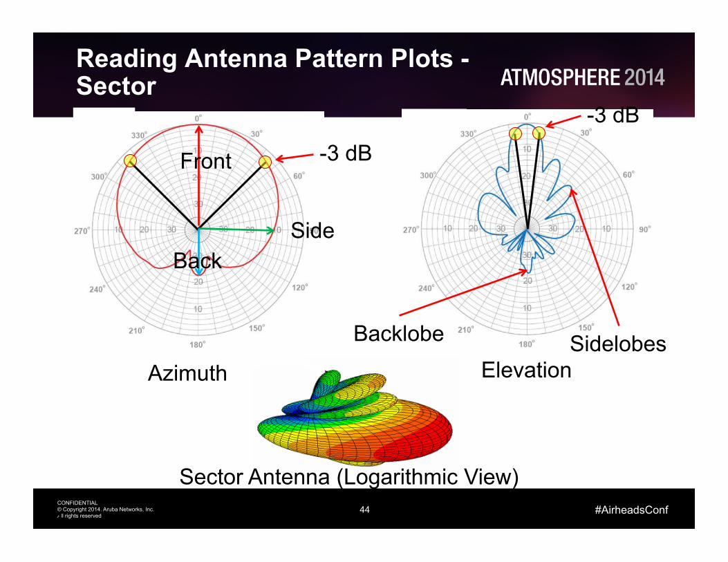
Reading Antenna Pattern Plots - Sector
44
Azimuth Elevation
Sector Antenna (Logarithmic View)
-3 dB
-3 dB
Sidelobes Backlobe
Front
Back Side
45 CONFIDENTIAL © Copyright 2014. Aruba Networks, Inc. All rights reserved
#AirheadsConf
802.11ac Beamforming
46 CONFIDENTIAL © Copyright 2014. Aruba Networks, Inc. All rights reserved
#AirheadsConf
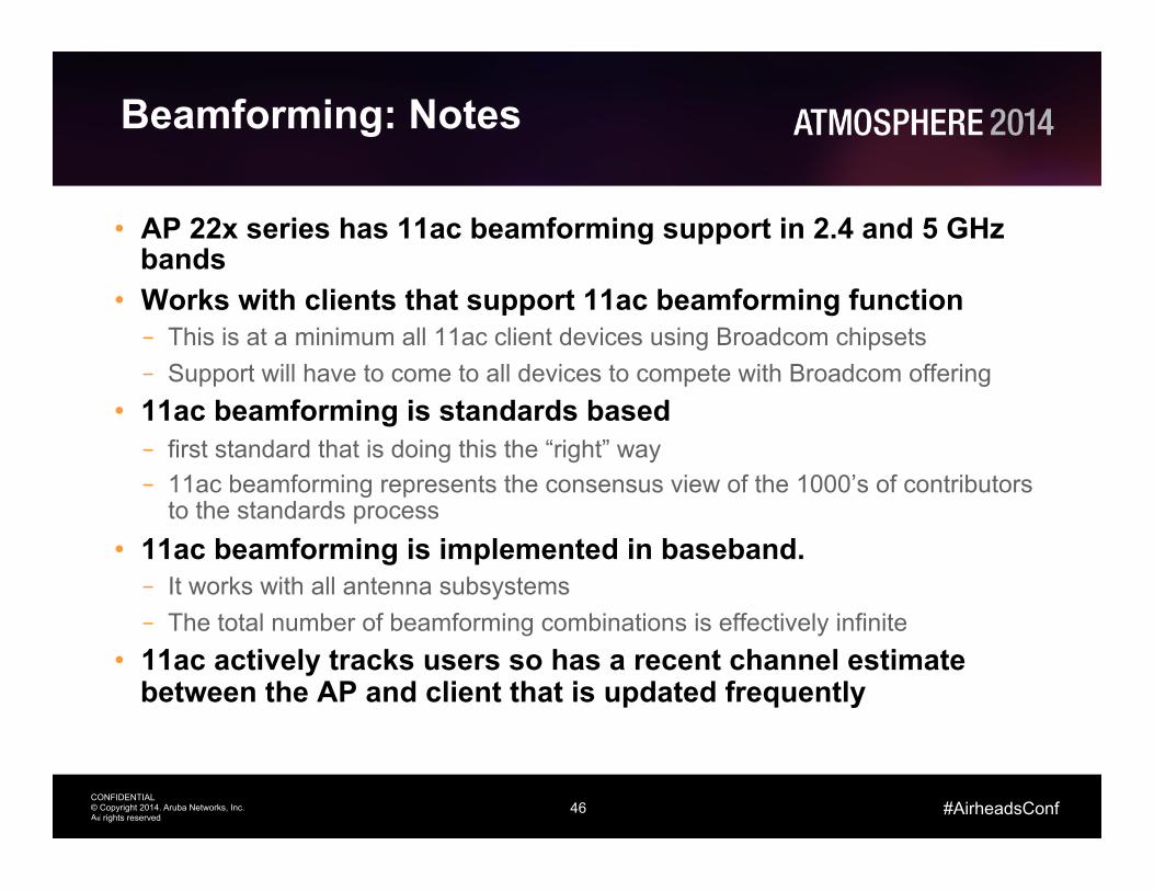
Beamforming: Notes
• AP 22x series has 11ac beamforming support in 2.4 and 5 GHz bands
• Works with clients that support 11ac beamforming function – This is at a minimum all 11ac client devices using Broadcom chipsets – Support will have to come to all devices to compete with Broadcom offering
• 11ac beamforming is standards based – first standard that is doing this the “right” way – 11ac beamforming represents the consensus view of the 1000’s of contributors
to the standards process • 11ac beamforming is implemented in baseband. – It works with all antenna subsystems – The total number of beamforming combinations is effectively infinite
• 11ac actively tracks users so has a recent channel estimate between the AP and client that is updated frequently
46

47 CONFIDENTIAL © Copyright 2014. Aruba Networks, Inc. All rights reserved
#AirheadsConf
Channel state information, implicit and explicit beamforming estimation
47
Explicit feedback for beamforming (802.11n and 802.11ac) 1 (Beamformer) Here’s a sounding frame 2 (Beamformee) Here’s how I heard the sounding frame 3 Now I will pre-code to match how you heard me
sounding frames
Beamformed frames
feedback from sounding
Explicit feedback for beamforming
Beamformer Beamformee
Actual CSI

48 CONFIDENTIAL © Copyright 2014. Aruba Networks, Inc. All rights reserved
#AirheadsConf
5− 4− 3− 2− 1− 0 1 2 3 4 51 10 4−×
1 10 3−×
0.01Antenna 1Antenna 2Antenna 3
Wavelengths
E Fi
eld
Am
plitu
de
Client Antennas
h11 h21
h31

49 CONFIDENTIAL © Copyright 2014. Aruba Networks, Inc. All rights reserved
#AirheadsConf
Line of Sight
• 3 stream AP • Smartphone – 1 Antenna/1 Stream
Client
AP
0
10
20
30
4050
60708090100110
120130
140
150
160
170
180
190
200
210
220230
240250 260 270 280
290300
310320
330
340
350

50 CONFIDENTIAL © Copyright 2014. Aruba Networks, Inc. All rights reserved
#AirheadsConf
Simple Reflection
• Let’s introduce two reflection surfaces and look at the impact of one bounce on each side
Client
AP
0
10
20
30
4050
60708090100110
120130
140
150
160
170
180
190
200
210
220230
240250 260 270 280
290300
310320
330
340
350
Virtual Antenna Pattern

51 CONFIDENTIAL © Copyright 2014. Aruba Networks, Inc. All rights reserved
#AirheadsConf
Multi Stream Client
• The reflections allow beamforming to send different streams with different antenna pattern through the system
Client
AP
0
10
20
30
4050
60708090100110
120130
140
150
160
170
180
190
200
210
220230
240250 260 270 280
290300
310320
330
340
350
0
10
20
30
4050
60708090100110
120130
140
150
160
170
180
190
200
210
220230
240250 260 270 280
290300
310320
330
340
350
0
10
20
30
4050
60708090100110
120130
140
150
160
170
180
190
200
210
220230
240250 260 270 280
290300
310320
330
340
350
Stre
am 1
Stre
am 2
S
tream
3

52 CONFIDENTIAL © Copyright 2014. Aruba Networks, Inc. All rights reserved
#AirheadsConf
0
10
20
30
4050
60708090100110
120130
140
150
160
170
180
190
200
210
220230
240250 260 270 280
290300
310320
330
340
350
0
10
20
30
4050
60708090100110
120130
140
150
160
170
180
190
200
210
220230
240250 260 270 280
290300
310320
330
340
350
0
10
20
30
4050
60708090100110
120130
140
150
160
170
180
190
200
210
220230
240250 260 270 280
290300
310320
330
340
350
11ac Beamforming across an 80 MHz channel
• The standards based algorithm actually works out patterns for each sub carrier
• Below is the pattern for stream 1 at 5460, 5500, 5540 MHz

53 CONFIDENTIAL © Copyright 2014. Aruba Networks, Inc. All rights reserved
#AirheadsConf
Aruba 11ac Solutions
54 CONFIDENTIAL © Copyright 2014. Aruba Networks, Inc. All rights reserved
#AirheadsConf
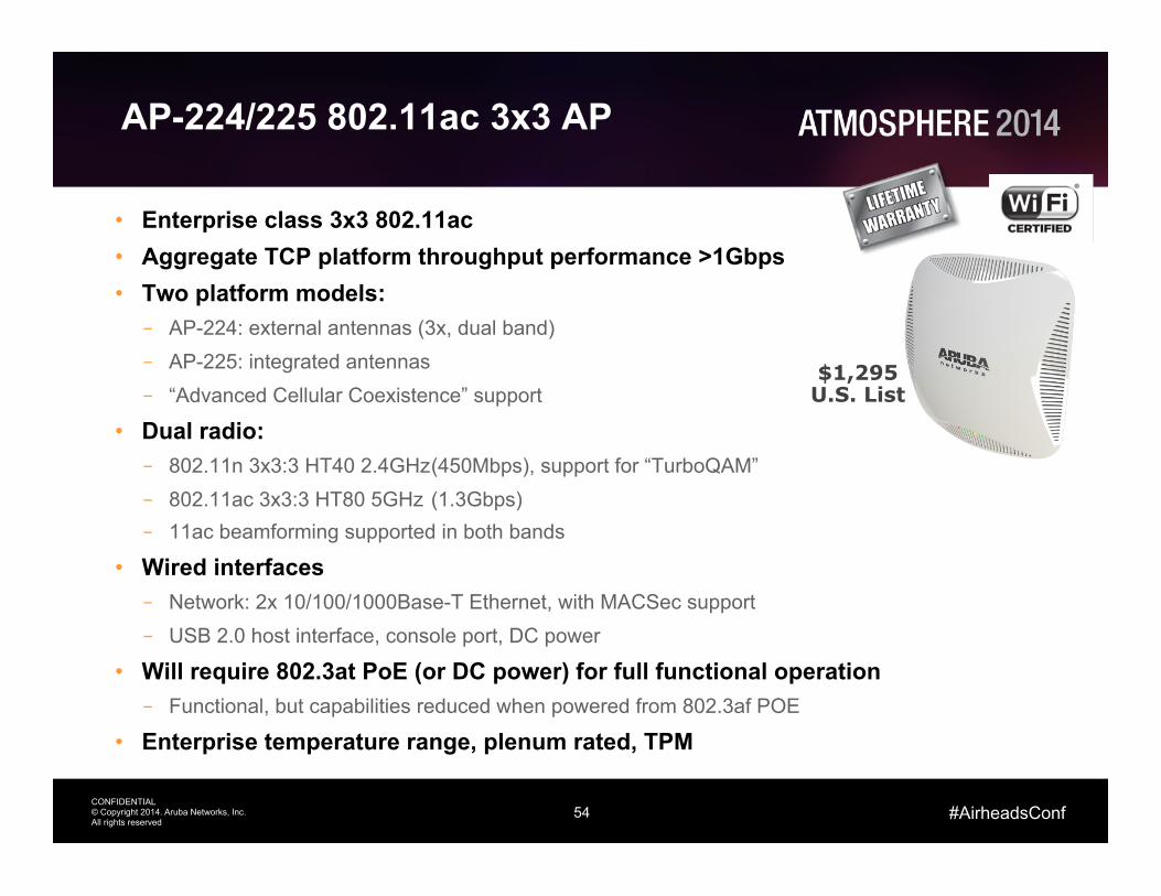
AP-224/225 802.11ac 3x3 AP
• Enterprise class 3x3 802.11ac • Aggregate TCP platform throughput performance >1Gbps • Two platform models: – AP-224: external antennas (3x, dual band) – AP-225: integrated antennas – “Advanced Cellular Coexistence” support
• Dual radio: – 802.11n 3x3:3 HT40 2.4GHz (450Mbps), support for “TurboQAM” – 802.11ac 3x3:3 HT80 5GHz (1.3Gbps) – 11ac beamforming supported in both bands
• Wired interfaces – Network: 2x 10/100/1000Base-T Ethernet, with MACSec support – USB 2.0 host interface, console port, DC power
• Will require 802.3at PoE (or DC power) for full functional operation – Functional, but capabilities reduced when powered from 802.3af POE
• Enterprise temperature range, plenum rated, TPM
$1,295 U.S. List

55 CONFIDENTIAL © Copyright 2014. Aruba Networks, Inc. All rights reserved
Thank You
#AirheadsConf