Embed Size (px)
Citation preview

Interface Modules
IM Series
www.turck.com
APPLICATION GUIDE

1 TURCK Inc. 3000 Campus Drive Minneapolis, MN 55441 Application Support: 1-800-544-7769 Fax: (763) 553-0708 www.turck.com
TURCKInterface Technology
TURCK's IM series of Isolating Intrinsically Safe Barriers is designed to be a simple and safe way to solve theproblems associated with the installation of equipment that is used in potentially explosive atmospheres.TURCK's IM series utilizes the intrinsically safe concept that is universally accepted, easy to apply and the safestway to install electronic measuring, monitoring and control equipment in potentially explosive atmospheres.The IM series uses state of the art circuitry and the latest technology to produce an unsurpassed product thatprovides the best explosion protection interfaces on the market.
The IM series of Intrinsically Safe Interface Devices is application specific: Each device is designed to work in aspecific application, be it analog input, analog output, discrete input, discrete output or others. The series wasdesigned to handle the vast majority of applications where instrumentation and control in potentially explosiveatmospheres is typically installed. A small number of interface devices will cover a large number of applications.This is a huge benefit, as limiting the number of different types of interfaces can significantly reduce the numberof spares. Reducing the number of model variations of those spares makes replacement or expansion mucheasier, while also consolidating stock and making inventory easier to manage.
Intrinsic safety has come of age with the introduction of the IM series of Intrinsically Safe Isolating Barriers, makingIS applications in potentially explosive atmospheres safe, simple and economically attractive.
Choosing an appropriate IM series Isolator is made simple with the help of this guide. The interface devicesoutlined within this guide allow you to make the appropriate selection for the corresponding field devices orconnections with ease.
IM Series Cabinet
Interface Modules

TURCK Inc. 3000 Campus Drive Minneapolis, MN 55441 Application Support: 1-800-544-7769 Fax: (763) 553-0708 www.turck.com 2
Interface ModuleApplication Guide
IM Introduction. . . . . . . . . . . . . . . . . . . . . . . . . . . . 1
Generic Specifications for IM Series . . . . . . . . . . . . . . . . . 3
Selection Guide . . . . . . . . . . . . . . . . . . . . . . . . . . . . 4
Isolation Switch Relays, IM1 . . . . . . . . . . . . . . . . . . . . . 5
Analog Data Transmitters, IM31 . . . . . . . . . . . . . . . . . . 31
Analog Input Repeaters/Supplies, IM33. . . . . . . . . . . . . . . 45
Temperature Converters, IM34 . . . . . . . . . . . . . . . . . . . 53
Analog Output Isolators, IM35 . . . . . . . . . . . . . . . . . . . 71
Solenoid Driver/Discrete Output Isolators, IM72. . . . . . . . . . 77
Approvals . . . . . . . . . . . . . . . . . . . . . . . . . . . . . . 85
Control Drawings . . . . . . . . . . . . . . . . . . . . . . . . . . 86

3 TURCK Inc. 3000 Campus Drive Minneapolis, MN 55441 Application Support: 1-800-544-7769 Fax: (763) 553-0708 www.turck.com
TURCKInterface Technology
Housing. . . . . . . . . . . . 18 mm, Single or Multi-Channel, 12-Pin Connector Connector Configuration
Housing. . . . . . . . . . . . 27 mm, Multi-Channel, 20-Pin Connector Connector Configuration
Material . . . . . . . . . . . . Polycarbonate/ABS Flammability Class V-0 UL94
Protection Level. . . . . . . . IP 20
Operating Temperature . . . -25 to +60°C (-13 to +140°F)
Storage Temperature . . . . . -40 to +80°C (-40 to +176°F)
Mounting . . . . . . . . . . . 35 mm Top Hat Rail
Units are Class I, Division 2 groups A, B, C or D hazardous area mountable in an appropriate enclosure.
Units may be mounted side by side without spacing requirements.
18 mm Housing Size 27 mm Housing Size
Generic Specifications for IM Series

TURCK Inc. 3000 Campus Drive Minneapolis, MN 55441 Application Support: 1-800-544-7769 Fax: (763) 553-0708 www.turck.com 4
Interface ModuleApplication Guide
Selection GuideFunction IM Series Part Number Pages
Isolation SwitchRelays
IM1-121Ex-RIM1-121-Ex-TIM1-22Ex-RIM1-22Ex-TIM1-22Ex-MTIM1-12Ex-RIM1-12Ex-TIM1-12Ex-MTIM1-451Ex-RIM1-451Ex-T
5 - 30
Analog DataTransmitters
IM31-11Ex-iIM31-11Ex-UIM31-12Ex-iIM31-22Ex-iIM31-22Ex-U
31 - 43
Analog InputRepeaters/Supplies
IM33-11Ex-Hi/24 VDCIM33-12Ex-Hi/24 VDCIM33-22Ex-Hi/24 VDC
45 - 52
TemperatureConverters
IM34-11Ex-iIM34-12Ex-RiIM34-11Ex-CiIM34-12Ex-CRi
53 - 70
Analog OutputIsolators
IM35-11Ex-Hi/24 VDCIM35-22Ex-Hi/24 VDC 71 - 76
SolenoidDriver/DiscreteOutput Isolators
IM72-11Ex/LIM72-22Ex/L 77 - 83

5 TURCK Inc. 3000 Campus Drive Minneapolis, MN 55441 Application Support: 1-800-544-7769 Fax: (763) 553-0708 www.turck.com
TURCKInterface Technology
Isolation Switch RelaysFor Use with NAMUR Proximity Sensors and Mechanical Switches
TURCK offers a wide range of isolating switch relays. These devices can serve various applications ranging from asingle dry contact switch input with a complimentary dry contact switch output, to four NAMUR proximity inputsand four transistor outputs, while also providing open and short-circuit protection in addition to alarmfunctionality.
Isolation switch relays may be used in general purpose applications, and most are certified for use in hazardous(explosive atmospheres) areas by various approvals bodies. These devices carry U.S., Canadian and Europeanapprovals that may be required in order to cover projects being engineered for use in locations throughout theworld. The devices share many common attributes, such as housings and removable terminal connectors. Mostare also available with the universal voltage (20-250 VAC/20-125 VDC) required to power the unit. All units havethe option for short-circuit and open-circuit (wire-break) protection: a simple series of switches that can bemanually configured by the user if the function is to be implemented. A resistor network (WM1 shown in Figure1) is required to incorporate these functions when using a mechanical (dry contact) switch for the hazardous areainputs.
The IM series of isolation switch relays is designed to handle the vast majority of applications where mechanicalswitches or NAMUR proximity sensors are used. Short-circuit and open-circuit (wire-break) functions areavailable for most devices. This function can be implemented by appropriately configuring the switches locatedon the top of the units. NAMUR proximity switches have no special requirements in order to incorporate thisfunction, simply set the switches to the appropriate positions.

TURCK Inc. 3000 Campus Drive Minneapolis, MN 55441 Application Support: 1-800-544-7769 Fax: (763) 553-0708 www.turck.com 6
Interface ModuleApplication Guide
Dry contact (mechanical switches) however, require the use of a resistor network in order for the additionalfunctions to operate properly. The incorporation of a ready made resistor network module (WM1 see Figure 1) isrecommended.
This section highlights the devices and provides a simple approach for installing the various models available.Examples of common applications are provided along with simple connection diagrams that allow any user toeasily and safely install these devices.
Typical and specific functions for each individual device are highlighted in the "Features" portion of thespecification pages. A handy pin-out reference chart is also provided for each device. Input and output commonconfigurations for use with NAMUR proximity sensors and dry contact mechanical switches, are also highlightedin this section.
Common Input Configuration for Proximity SensorsNAMUR 2-wire proximity sensors are specifically designed to work with TURCK isolation switch relays. No entitycalculations are required, as all NAMUR proximity sensors and associated apparatus with NAMUR inputs (TURCKisolation switch relays) are designed to be 100% compatible without the requirement to calculate entityparameters. These calculations are accounted for in the design of both the field devices (proximity sensors) andthe interfaces (barriers). All NAMUR proximity sensors are compatible with NAMUR interface devices in allclassified areas.
The 2-wire configuration is standardized so the blue wire is always negative and the brown wire is always positive.Reversing these connections will not damage the device, however it will not function.
Connection diagrams for individual devices are shown in the product specification description pages.
Common Input Configurations for Dry Contact Mechanical SwitchesSimple switch inputs are easily accommodated by the NAMUR input interface units. Switches are not required tobe approved as intrinsically safe devices. Simple switches are defined as "simple apparatus" by the nationalelectrical code as: (NEC 504-2)A device that will neither generate nor store more than 1.2 V, 0.1 A, 25 mW, or 20 μ.
Using a simple switch does require the use of a resistor network (WM1) if the short-circuit and open-circuit(wire-break) functions are not used. These functions are not required and can be disabled by simply switchingthe function "OFF" using the configuration switches on the top of the units.
Figure 1

7 TURCK Inc. 3000 Campus Drive Minneapolis, MN 55441 Application Support: 1-800-544-7769 Fax: (763) 553-0708 www.turck.com
TURCKInterface Technology
Part number keys are to assist in IDENTIFICATION ONLY. Consult factory for catalog items not identified.
IM1-121Ex-RIsolation Switch RelayInterface ModuleSingle InputTwo Non-Hazardous Area Relay SwitchesOne Non-Hazardous Area Alarm SwitchIntrinsically Safe Associated ApparatusRelay Switch
IM1-22Ex-MTIsolation Switch RelayInterface ModuleTwo InputsTwo Non-Hazardous Area Relay SwitchesIntrinsically Safe Associated ApparatusMOSFET Switch
IM1-451Ex-TIsolation Switch RelayInterface ModuleFour InputsFive Non-Hazardous Area Relay SwitchesOne Non-Hazardous Area Alarm SwitchIntrinsically Safe Associated ApparatusTransistor Switch
Extension Examples:
Isolation Switch Relays Part Number Key
Interface Module
1 = Isolation Switch Relay
Function Group
Number of Inputs
IM 1 - 1 2 1 Ex - R
Intrinsically Safe Associated Apparatus
R =Relay SwitchT = Transistor SwitchMT= MOSFET Switch
Non-Hazardous Area Switching Circuits
Number of Non-Hazardous Area OutputsReflecting Hazardous Area Input Status
Number of Additional Non-Hazardous Area Alarm Outputs

TURCK Inc. 3000 Campus Drive Minneapolis, MN 55441 Application Support: 1-800-544-7769 Fax: (763) 553-0708 www.turck.com 8
Interface ModuleApplication Guide
All IM1-xxx Modules are Equipped With:
Intrinsically Safe Field TerminalsThis feature allows the use of any certified NAMUR sensor or dry contact mechanical switch (simple apparatus) tobe used in any area classification without risk of explosion.
Universal Input VoltageThis feature allows any power supply with an output of 20-250 VAC or 20-125 VDC to be used to power theunits. This provides extreme flexibility in the source power required to operate the units.
Removable "Keyed" TerminalsThis feature allows easy wiring. The keyed connectors assure safe and accurate installation. Terminals can beremoved and wired without physically making the connections in tight quarters. Cable harnesses that incorporatethese connectors can actually be wired outside cabinets, and assembly is completed by plugging in the terminalsto the corresponding barrier. A bus power configuration is also available. That allows several barrier's powerconnections to be bussed in a daisy-chain configuration, further reducing installation time and wiring.Replacement of units when necessary is also simplified.
Short-circuit and Open-circuit DetectionThis feature allows monitoring of field circuits for wire faults. The function is selectable and can be disabled if notrequired or desired. NAMUR sensors need no accessory to provide the function. Dry contact mechanicalswitches require a resistor network to properly function. The WM1 resistor network module will provide thisfunction, or a network of discrete resistors can be added by the user. Utilization of a common non-hazardousarea alarm circuit signifies a fault in the hazardous area wiring.
N.O./N.C. ConfigurationThis feature allows the input function to be selected as a normally open or normally closed output. Each channelcan be separately configured depending on module type.
Galvanic IsolationThis feature provides isolation between inputs, outputs and the power supply. In some cases, individual outputsare also isolated from each other.
Switching Status and Power Indication LEDsThis feature provides a visual indication for the switching status of each channel. The green LED indicates thatthe unit is powered. The dual color LEDs indicate switching (yellow) and fault status (red). A fault status on aninput disables the corresponding output relay.
Housing SizesThe size depends on the number of channels. All 4-channel devices utilize the wider 27 mm housing, while the1 and 2-channel devices are housed in the 18 mm style. Both are the same height, and can be mounted on aDIN-rail or flush mounted on a panel.

9 TURCK Inc. 3000 Campus Drive Minneapolis, MN 55441 Application Support: 1-800-544-7769 Fax: (763) 553-0708 www.turck.com
TURCKInterface Technology
Hazardous (Classified) AreaThe hazardous area terminals of the IM series switch input isolators are suitable for use with mechanical switch orNAMUR inputs in ALL area classifications.
Shown here is the common input configuration for a NAMUR proximity sensor. The wires are color coded andblue is always the (-) terminal and brown is always the (+) terminal.
Open-circuit (wire-break) and short-circuit can be configured by the switch settings on the top of the unit, if theunit is equipped with this function. No special conditions are required to incorporate the function when usingNAMUR proximity sensors.
Division/Zone 2 or Non-Hazardous AreasIM units are certified to be mounted in a Division/Zone 2 area. Units must be housed in an appropriateenclosure suitable for the environment in which they will be installed.
Explosion-proof or purged enclosures are not required for use in this area classification with the TURCK IM series.
Non-Hazardous (Non-classified) AreaNon-hazardous area terminals are designed to be connected to apparatus in a non-classified area.The equipment may consist of alarm circuits, PLC or DCS controllers or other similar types of equipment.
WM1 Configuration

TURCK Inc. 3000 Campus Drive Minneapolis, MN 55441 Application Support: 1-800-544-7769 Fax: (763) 553-0708 www.turck.com 10
Interface ModuleApplication Guide

11 TURCK Inc. 3000 Campus Drive Minneapolis, MN 55441 Application Support: 1-800-544-7769 Fax: (763) 553-0708 www.turck.com
TURCKInterface Technology
This 1 channel intrinsically safe interface device is designed to accommodate 1 switch or NAMUR proximity sensor inputfrom a hazardous area and repeat the change of state of the field circuits to a control system located in a non-hazardousarea.
The non-hazardous area output is a SPST switch reflecting the corresponding input change of state from the field circuit.
The device also incorporates a separate SPST Non-Hazardous area alarm switch for monitoring open or short-circuits in thehazardous area.
Functional Description:
• 1 channel input for NAMUR sensors or mechanical switches
• Monitoring of field wiring for open or short-circuit (if required)
• Configuration switches on top of unit for easy access
• 2 non-hazardous area switch outputs, 1 for alarm function
• Selectable N.O./N.C. outputs
Features:
IM1-121Ex-R Isolation Switch Relays
Inputs: Hazardous Area Outputs: Non-Hazardous Area
Supply Voltage - (20-250 VAC or 20-125 VDC)Inputs . . . . . . . . . . . (8.2 V, 8.2 mA)Switching Threshold . . . . 1.55 mAHysteresis . . . . . . . . . Typical 0.2 mAOpen-circuit Threshold . . ≤0.1 mAShort-circuit Threshold . . . ≥6.0 mA
2 Relays, 1 N.O. Contact Each
Voltage . . . . . . . . . . ≥250 VAC/120 VDCCurrent . . . . . . . . . . ≥2 A per channelCapacity . . . . . . . . . . ≥500 VA/60 W per channelSwitch Frequency . . . . . ≥10 HzContacts . . . . . . . . . . Silver-Alloy + Au (3 micro µ)
Electrical Parameters:
For entity parameters see control drawings on pages 86-91.

TURCK Inc. 3000 Campus Drive Minneapolis, MN 55441 Application Support: 1-800-544-7769 Fax: (763) 553-0708 www.turck.com 12
Interface ModuleApplication Guide
Isolation Switch Relays IM1-121Ex-R
Pin # Terminal Function
1 (+) to Field Device
2 No Connection
3 No Connection
4 (-) to Field Device
5 No Connection
6 No Connection
7 Non-Hazardous Area Switch #1
8 Non-Hazardous Area Switch #2 Alarm
9 Non-Hazardous Area Switch #2 Alarm
10 Non-Hazardous Area Switch #1
11 Module Power (+) or AC
12 Module Power (-) or AC

13 TURCK Inc. 3000 Campus Drive Minneapolis, MN 55441 Application Support: 1-800-544-7769 Fax: (763) 553-0708 www.turck.com
TURCKInterface Technology
IM1-121Ex-T Isolation Switch Relays
This 1 channel intrinsically safe interface device is designed to accommodate 1 switch or NAMUR proximity sensor inputfrom a hazardous area and repeat the change of state of the field circuits to a control system located in a non-hazardousarea.
The non-hazardous area output is a NPN Transistor reflecting the corresponding input change of state from the field circuitwhen properly configured.
Functional Description:
• 1 channel input for NAMUR sensors or mechanical switches
• Monitoring of field wiring for open or short-circuit (if required)
• Configuration switches on top of unit for easy access
• 2 isolated short-circuit protected non-hazardous area NPN transistor outputs, 1 for alarm function
• Selectable N.O./N.C. outputs
Features:
Inputs: Hazardous Area Outputs: Non-Hazardous Area
Supply Voltage - (20-250 VAC or 20-125 VDC)Inputs . . . . . . . . . . . (8.2 V, 8.2 mA)Switching Threshold . . . . 1.55 mAHysteresis . . . . . . . . . Typical 0.2 mAOpen-circuit Threshold . . ≤0.1 mAShort-circuit Threshold . . . ≥6.0 mA
2 Transistors, Potential Free Short-Circuit Protected
Switching Voltage . . . . . ≤30 VDCSwitch Current . . . . . . . ≤50 mA per channelSwitch Frequency . . . . . ≤5 kHzVoltage Drop. . . . . . . . ≤1.3 V
Electrical Parameters:
For entity parameters see control drawings on pages 86-91.

TURCK Inc. 3000 Campus Drive Minneapolis, MN 55441 Application Support: 1-800-544-7769 Fax: (763) 553-0708 www.turck.com 14
Interface ModuleApplication Guide
Isolation Switch Relays IM1-121Ex-T
Pin # Terminal Function
1 (+) to Field Device
2 No Connection
3 No Connection
4 (-) to Field Device
5 No Connection
6 No Connection
7 Non-Hazardous Area Transistor (+)
8 Non-Hazardous Area Trans Alarm (+)
9 Non-Hazardous Area Trans Alarm (-)
10 Non-Hazardous Area Transistor (-)
11 Module Power (+) or AC
12 Module Power (-) or AC

15 TURCK Inc. 3000 Campus Drive Minneapolis, MN 55441 Application Support: 1-800-544-7769 Fax: (763) 553-0708 www.turck.com
TURCKInterface Technology
IM1-22Ex-R Isolation Switch Relays
This 2 channel intrinsically safe interface device is designed to accommodate two switches or NAMUR proximity sensorinputs from a hazardous area and repeat the change of state of the field circuits to a control system located in anon-hazardous area.
The non-hazardous area outputs are two separate SPST switches reflecting the corresponding change of state from eachindividual input of the field circuit.
Functional Description:
• 2 channel input for NAMUR sensors or mechanical switches
• Monitoring of field wiring for open or short-circuit (if required)
• Configuration switches on top of unit for easy access
• 2 SPST non-hazardous area outputs; 1 for each channel
• Selectable N.O./N.C. outputs
Features:
Inputs: Hazardous Area Outputs: Non-Hazardous Area
Supply Voltage - (20-250 VAC or 20-125 VDC)Inputs . . . . . . . . . . . (8.2 V, 8.2 mA)Switching Threshold . . . . 1.55 mAHysteresis . . . . . . . . . Typical 0.2 mAOpen-circuit Threshold . . ≤0.1 mAShort-circuit Threshold . . . ≥6.0 mA
2 Relays, 1 N.O. Contact Each
Voltage. . . . . . . . . . . ≥250 VAC/120 VDCCurrent . . . . . . . . . . ≥2 A per channelCapacity . . . . . . . . . . ≥500 VA / 60 W per channelSwitch Frequency . . . . . ≥10 HzContacts . . . . . . . . . . Silver-Alloy + Au (3 micro µ)
Electrical Parameters:
For entity parameters see control drawings on pages 86-91.

TURCK Inc. 3000 Campus Drive Minneapolis, MN 55441 Application Support: 1-800-544-7769 Fax: (763) 553-0708 www.turck.com 16
Interface ModuleApplication Guide
Isolation Switch Relays IM1-22Ex-R
Pin # Terminal Function
1 (+) to Field Device #1
2 (+) to Field Device #2
3 No Connection
4 (-) to Dield Device #1
5 (-) to Field Device #2
6 No Connection
7 Non-Hazardous Area Switch #1
8 Non-Hazardous Area Switch #2
9 Non-Hazardous Area Switch #2
10 Non-Hazardous Area Switch #1
11 Module Power (+) or AC
12 Module Power (-) or AC

17 TURCK Inc. 3000 Campus Drive Minneapolis, MN 55441 Application Support: 1-800-544-7769 Fax: (763) 553-0708 www.turck.com
TURCKInterface Technology
IM1-22Ex-T Isolation Switch Relays
This 2 channel intrinsically safe interface device is designed to accommodate two switches or NAMUR proximity sensorsinput from a hazardous area and repeat the change of state of the field circuits to a control system located in anon-hazardous area.
The non-hazardous area outputs are two separate NPN transistors reflecting the corresponding change of state from eachindividual input of the field circuit when properly configured.
Functional Description:
• 2 channel input for NAMUR sensors or mechanical switches
• Monitoring of field wiring for open or short-circuit (if required)
• Configuration switches on top of unit for easy access
• 2 isolated short-circuit protected NPN transistor non-hazardous area outputs; 1 for each channel
• Selectable N.O./N.C. outputs
Features:
Inputs: Hazardous Area Outputs: Non-Hazardous Area
Supply Voltage - (20-250 VAC or 20-125 VDC)Inputs . . . . . . . . . . . (8.2 V, 8.2 mA)Switching Threshold . . . . 1.55 mAHysteresis . . . . . . . . . Typical 0.2 mAOpen-circuit Threshold . . ≤0.1 mAShort-circuit Threshold . . . ≥6.0 mA
2 Transistors, Potential Free Short-Circuit Protected
Switching Voltage . . . . . ≤30 VDCSwitch Current . . . . . . . ≤50 mA per channelSwitch Frequency . . . . . ≤5 kHzVoltage Drop. . . . . . . . ≤1.3 V
Electrical Parameters:
For entity parameters see control drawings on pages 86-91.

TURCK Inc. 3000 Campus Drive Minneapolis, MN 55441 Application Support: 1-800-544-7769 Fax: (763) 553-0708 www.turck.com 18
Interface ModuleApplication Guide
Isolation Switch Relays IM1-22Ex-T
Pin # Terminal Function
1 (+) to Field Device #1
2 (+) to Field Device #2
3 No Connection
4 (-) to Field Device #1
5 (-) to Field Device #2
6 No Connection
7 Non-Hazardous Area Transistor #1 (+)
8 Non-Hazardous Area Transistor #2 (+)
9 Non-Hazardous Area Transistor #2 (-)
10 Non-Hazardous Area Transistor #1 (-)
11 Module Power (+) or AC
12 Module Power (-) or AC

19 TURCK Inc. 3000 Campus Drive Minneapolis, MN 55441 Application Support: 1-800-544-7769 Fax: (763) 553-0708 www.turck.com
TURCKInterface Technology
IM1-22Ex-MT Isolation Switch Relays
This 2 channel intrinsically safe interface device is designed to accommodate two switches or NAMUR proximity sensorsinput from a hazardous area and repeat the change of state of the field circuits to a control system located in anon-hazardous area.
The non-hazardous area outputs are two separate MOSFET transistors reflecting the corresponding change of state from eachindividual input of the field circuit when properly configured.
Functional Description:
• 2 channel input for NAMUR sensors or mechanical switches
• Monitoring of field wiring for open or short-circuit (if required)
• Configuration switches on top of unit for easy access
• 2 isolated non-hazardous area unipolar MOSFET outputs allow switching voltages up to 250 VAC at a maximum frequencyof 1 kHz, 1 for each channel
• Selectable N.O./N.C. outputs
Features:
Inputs: Hazardous Area Outputs: Non-Hazardous Area
Supply Voltage - (20-250 VAC or 20-125 VDC)Inputs . . . . . . . . . . . (8.2 V, 8.2 mA)Switching Threshold . . . . 1.55 mAHysteresis . . . . . . . . . Typical 0.2 mAOpen Circuit Threshold . . ≤0.1 mAShort Circuit Threshold. . . ≥6.0 mA
2 MOSFET, Potential Free
Switching Voltage . . . . . ≥250 VAC/120 VDCSwitch Current . . . . . . . ≤90 mA per channelSwitch Capacity . . . . . . 22.5 VA/10.8 W per channelSwitch Capacity . . . . . . ≤1 kHz
Electrical Parameters:
For entity parameters see control drawings on pages 86-91.

TURCK Inc. 3000 Campus Drive Minneapolis, MN 55441 Application Support: 1-800-544-7769 Fax: (763) 553-0708 www.turck.com 20
Interface ModuleApplication Guide
Isolation Switch Relays IM1-22Ex-MT
Pin # Terminal Function
1 (+) to Field Device
2 (+) to Field Device
3 No Connection
4 (-) to Field Device
5 (-) to Field Device
6 No Connection
7 Non-Hazardous Area MOSFET #1 D
8 Non-Hazardous Area MOSFET #2 D
9 Non-Hazardous Area MOSFET #2 S
10 Non-Hazardous Area MOSFET #1 S
11 Module Power (+) or AC
12 Module Power (-) or AC

21 TURCK Inc. 3000 Campus Drive Minneapolis, MN 55441 Application Support: 1-800-544-7769 Fax: (763) 553-0708 www.turck.com
TURCKInterface Technology
IM1-12Ex-R Isolation Switch Relays
This 1 channel intrinsically safe interface device is designed to accommodate 1 switch or NAMUR proximity sensor inputfrom a hazardous area and repeat the change of state of the field circuits to a control system located in a non-hazardousarea.
The non-hazardous area outputs are two separate SPST switches reflecting the corresponding input change of state from thefield circuit.
Functional Description:
• 1 channel input for NAMUR sensors or mechanical switches
• Monitoring of field wiring for open or short-circuit (if required)
• Configuration switches on top of unit for easy access
• 2 non-hazardous area switch outputs; 1 for alarm function
• Selectable N.O./N.C. outputs
Features:
Inputs: Hazardous Area Outputs: Non-Hazardous Area
Supply Voltage - (20-250 VAC or 20-125 VDC)Inputs . . . . . . . . . . . (8.2 V, 8.2 mA)Switching Threshold . . . . 1.55 mAHysteresis . . . . . . . . . Typical 0.2 mAOpen-circuit Threshold . . ≤0.1 mAShor-circuit Threshold . . . ≥6.0 mA
2 Relays, 1 N.O. Contact Each
Voltage. . . . . . . . . . . ≥250 VAC/120 VDCCurrent . . . . . . . . . . ≥2 A per channelCapacity . . . . . . . . . . ≥500 VA /60 W per channelSwitch Frequency . . . . . ≥10 HzContacts . . . . . . . . . . Silver-Alloy + Au (3 micro µ)
Electrical Parameters:
For entity parameters see control drawings on pages 86-91.

TURCK Inc. 3000 Campus Drive Minneapolis, MN 55441 Application Support: 1-800-544-7769 Fax: (763) 553-0708 www.turck.com 22
Interface ModuleApplication Guide
Isolation Switch Relays IM1-12Ex-R
Pin # Terminal Function
1 (+) to Field Device
2 No Connection
3 No Connection
4 (-) to Field Device
5 No Connection
6 No Connection
7 Non-Hazardous Area Switch #1
8 Non-Hazardous Area Switch #2
9 Non-Hazardous Area Switch #2
10 Non-Hazardous Area Switch #1
11 Module Power (+) or AC
12 Module Power (-) or AC

23 TURCK Inc. 3000 Campus Drive Minneapolis, MN 55441 Application Support: 1-800-544-7769 Fax: (763) 553-0708 www.turck.com
TURCKInterface Technology
IM1-12Ex-T Isolation Switch Relays
This 1 channel intrinsically safe interface device is designed to accommodate 1 switch or NAMUR proximity sensor inputfrom a hazardous area and repeat the change of state of the field circuits to a control system located in a non-hazardousarea.
The non-hazardous area outputs are two separate NPN transistors reflecting the corresponding input change of state from thefield circuit when properly configured.
Functional Description:
• 1 channel input for NAMUR sensors or mechanical switches
• Monitoring of field wiring for open or short-circuit (if required)
• Configuration switches on top of unit for easy access
• 2 isolated short-circuit protected non-hazardous area NPN transistor outputs; 1 for Alarm function
• Selectable N.O./N.C. outputs
Features:
Inputs: Hazardous Area Outputs: Non-Hazardous Area
Supply Voltage - (20-250 VAC or 20-125 VDC)Inputs . . . . . . . . . . . (8.2 V, 8.2 mA)Switching Threshold . . . . 1.55 mAHysteresis . . . . . . . . . Typical 0.2 mAOpen-circuit Threshold . . ≤0.1 mAShort-circuit Threshold . . . ≥6.0 mA
2 Transistors, Potential Free Short-Circuit Protected
Switching Voltage . . . . . ≤30 VDCSwitch Current . . . . . . . ≤50 mA per channelSwitch Frequency . . . . . ≤5 HzVoltage Drop. . . . . . . . ≤1.3 V
Electrical Parameters:
For entity parameters see control drawings on pages 86-91.

TURCK Inc. 3000 Campus Drive Minneapolis, MN 55441 Application Support: 1-800-544-7769 Fax: (763) 553-0708 www.turck.com 24
Interface ModuleApplication Guide
Isolation Switch Relays IM1-12Ex-T
Pin # Terminal Function
1 (+) to Field Device
2 No Connection
3 No Connection
4 (-) to Field Device
5 No Connection
6 No Connection
7 Non-Hazardous Area Transistor #1
8 Non-Hazardous Area Transistor #2
9 Non-Hazardous Area Transistor #2
10 Non-Hazardous Area Transistor #1
11 Module Power (+) or AC
12 Module Power (-) or AC

25 TURCK Inc. 3000 Campus Drive Minneapolis, MN 55441 Application Support: 1-800-544-7769 Fax: (763) 553-0708 www.turck.com
TURCKInterface Technology
IM1-12Ex-MT Isolation Switch Relays
This 1 channel intrinsically safe interface device is designed to accommodate 1 switch or NAMUR proximity sensor inputfrom a hazardous area and repeat the change of state of the field circuits to a control system located in a non-hazardousarea.
The non-hazardous area outputs are two separate MOSFET Transistors reflecting the corresponding input change of statefrom the field circuit when properly configured.
Functional Description:
• 1 channel input for NAMUR sensors or mechanical switches
• Monitoring of field wiring for open or short-circuit (if required)
• Configuration switches on top of unit for easy access
• 2 isolated non-hazardous area unipolar MOSFET outputs allow switching voltages up to 250 VACat a maximum frequency of 1 kHz
• Selectable N.O./N.C. outputs
Features:
Inputs: Hazardous Area Outputs: Non-Hazardous Area
Supply Voltage - (20-250 VAC or 20-125 VDC)Inputs . . . . . . . . . . . (8.2 V, 8.2 mA)Switching Threshold . . . . 1.55 mAHysteresis . . . . . . . . . Typical 0.2 mAOpen-circuit Threshold . . ≤0.1 mAShort-circuit Threshold . . . ≥6.0 mA
2 MOSFET, Potential Free
Switch Current . . . . . . . ≤90 mA per channelSwitch Capacity . . . . . . 22.5 VA/10.8 W per channelSwitch Capacity . . . . . . ≤1 kHz
Electrical Parameters:
For entity parameters see control drawings on pages 86-91.

TURCK Inc. 3000 Campus Drive Minneapolis, MN 55441 Application Support: 1-800-544-7769 Fax: (763) 553-0708 www.turck.com 26
Interface ModuleApplication Guide
Isolation Switch Relays IM1-12Ex-MT
Pin # Terminal Function
1 (+) to Field Device
2 No Connection
3 No Connection
4 (-) to Field Device
5 No Connection
6 No Connection
7 Non-Hazardous Area MOSFET #1 D
8 Non-Hazardous Area MOSFET #2 D Alarm
9 Non-Hazardous Area MOSFET #2 S Alarm
10 Non-Hazardous Area MOSFET #1 S
11 Module Power (+) or AC
12 Module Power (-) or AC

27 TURCK Inc. 3000 Campus Drive Minneapolis, MN 55441 Application Support: 1-800-544-7769 Fax: (763) 553-0708 www.turck.com
TURCKInterface Technology
IM1-451Ex-R Isolation Switch Relays
This 4 channel intrinsically safe interface device is designed to accommodate four switches or NAMUR proximity sensorinputs or any combination of the two from a hazardous area and repeat the change of state of the field circuits to a controlsystem located in a non-hazardous area.
The non-hazardous area outputs are four separate SPST switches reflecting the corresponding change of state from eachindividual input of the field circuit, to its appropriate corresponding output.
A common alarm switch for all four channels is also incorporated.
Functional Description:
• 4 channel input for NAMUR sensors or mechanical switches
• Monitoring of field wiring for open or short-circuit (if required)
• Configuration switches on top of unit for easy access
• 4 SPST non-hazardous area outputs; 1 for each channel and 1 common alarm
• Selectable N.O./N.C. outputs
Features:
Inputs: Hazardous Area Outputs: Non-Hazardous Area
Supply Voltage - (20-250 VAC or 20-125 VDC)Inputs . . . . . . . . . . . (8.2 V, 8.2 mA)Switching Threshold . . . . 1.55 mAHysteresis . . . . . . . . . Typical 0.2 mAOpen-circuit Threshold . . ≤0.1 mAShort-circuit Threshold . . . ≥6.0 mA
5 Relays, 1 N.O. Contact Each
Switching Voltage . . . . . ≤250 VAC/120 VDCSwitch Current . . . . . . . ≤3 A per channelSwitch Capacity . . . . . . ≤750 VAC per channelSwitch Frequency . . . . . ≤10 kHzContacts . . . . . . . . . . Silver-Alloy + Au (3 micro µ)
Electrical Parameters:
For entity parameters see control drawings on pages 86-91.

TURCK Inc. 3000 Campus Drive Minneapolis, MN 55441 Application Support: 1-800-544-7769 Fax: (763) 553-0708 www.turck.com 28
Interface ModuleApplication Guide
Isolation Switch Relays IM1-451Ex-R
Pin # Terminal Function
1 (+) to Field Device #1
2 (-) to Field Device #1
3 No Connection
4 (+) to Field Device #2
5 (-) to Field Device #2
6 (+) to Field Device #3
7 (-) to Field Device #3
8 No Connection
9 (+) to Field Device #4
10 (-) to Field Device #4
Pin # Terminal Function
11 Non-Hazardous Area Sw 3 & 4 common
12 Non-Hazardous Area Switch #3 (-)
13 Non-Hazardous Area Switch #4 (-)
14 Non-Hazardous Area Switch Alarm
15 Non-Hazardous Area Switch Alarm
16 Non-Hazardous Area Sw 1 & 2 common
17 Non-Hazardous Area Switch #1 (-)
18 Non-Hazardous Area Switch #2 (-)
19 Module Power (+) or AC
20 Module Power (-) or AC

29 TURCK Inc. 3000 Campus Drive Minneapolis, MN 55441 Application Support: 1-800-544-7769 Fax: (763) 553-0708 www.turck.com
TURCKInterface Technology
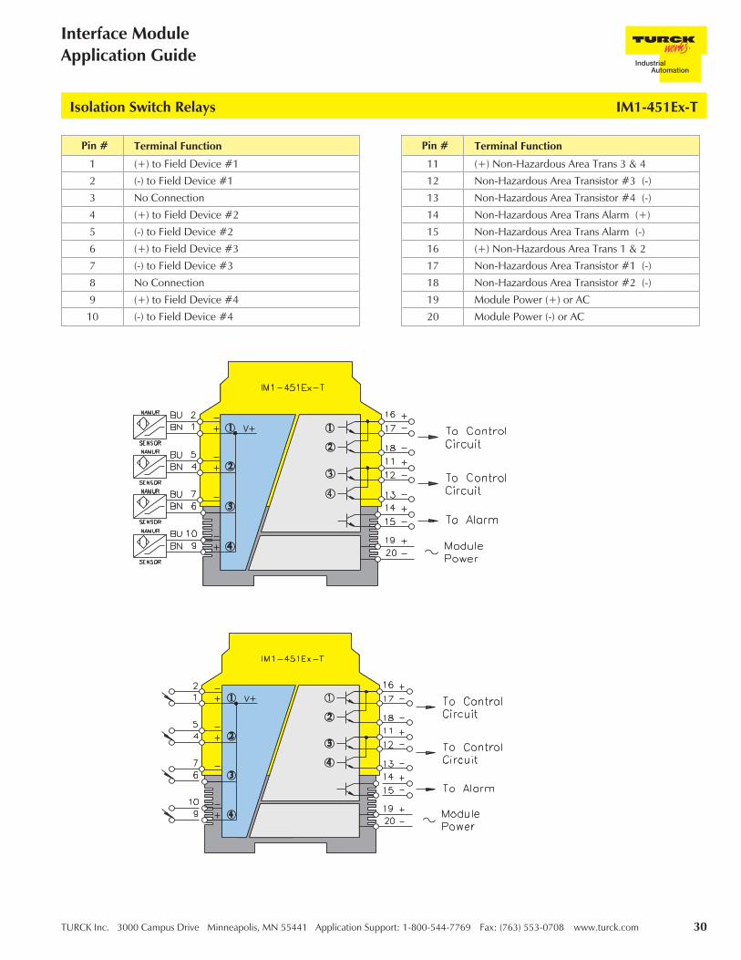
IM1-451Ex-T Isolation Switch Relays
This 4 channel intrinsically safe interface device is designed to accommodate four switches or NAMUR proximity sensorinputs or any combination of the two from a hazardous area and repeat the change of state of the field circuits to a controlsystem located in a non-hazardous area.
The non-hazardous area outputs are four separate open collector transistors reflecting the corresponding change of state fromeach individual input of the field circuit, to its appropriate corresponding output when appropriately configured.
A common alarm transistor for all four channels is also incorporated.
Functional Description:
• 4 channel input for NAMUR sensors or mechanical switches
• Monitoring of field wiring for open or short-circuit (if required)
• Configuration switches on top of unit for easy access
• 2 isolated short-circuit protected NPN transistor non-hazardous area outputs; 1 for each channel and 1 alarm
• Selectable N.O./N.C. outputs
Features:
Inputs: Hazardous Area Outputs: Non-Hazardous Area
Supply Voltage - (20-250 VAC or 20-125 VDC)Inputs . . . . . . . . . . . (8.2 V, 8.2 mA)Switching Threshold . . . . 1.55 mAHysteresis . . . . . . . . . Typical 0.2 mAOpen-circuit Threshold . . ≤0.1 mAShort-circuit Threshold . . . ≥6.0 mA
5 Transistors, Potential Free Short-Circuit Protected
Switching Voltage . . . . . ≤30 VDCSwitch Current . . . . . . . ≤50 mA per channelSwitch Frequency . . . . . ≤3 kHzVoltage Drop. . . . . . . . ≤2.5 V
Electrical Parameters:
For entity parameters see control drawings on pages 86-91.
TURCK Inc. 3000 Campus Drive Minneapolis, MN 55441 Application Support: 1-800-544-7769 Fax: (763) 553-0708 www.turck.com 30
Interface ModuleApplication Guide
Isolation Switch Relays IM1-451Ex-T
Pin # Terminal Function
1 (+) to Field Device #1
2 (-) to Field Device #1
3 No Connection
4 (+) to Field Device #2
5 (-) to Field Device #2
6 (+) to Field Device #3
7 (-) to Field Device #3
8 No Connection
9 (+) to Field Device #4
10 (-) to Field Device #4
Pin # Terminal Function
11 (+) Non-Hazardous Area Trans 3 & 4
12 Non-Hazardous Area Transistor #3 (-)
13 Non-Hazardous Area Transistor #4 (-)
14 Non-Hazardous Area Trans Alarm (+)
15 Non-Hazardous Area Trans Alarm (-)
16 (+) Non-Hazardous Area Trans 1 & 2
17 Non-Hazardous Area Transistor #1 (-)
18 Non-Hazardous Area Transistor #2 (-)
19 Module Power (+) or AC
20 Module Power (-) or AC

31 TURCK Inc. 3000 Campus Drive Minneapolis, MN 55441 Application Support: 1-800-544-7769 Fax: (763) 553-0708 www.turck.com
TURCKInterface Technology
Analog Data Transmitters
Analog data transmitters are a selection of devices that allow the transmission of hazardous area analog signals toa non-hazardous area as a direct one-to-one, or with a slight variation that is sometimes desired for specificapplications.
The Analog Isolating Transmitters can transfer 4/20 mA, 0/20 mA, 0-10 V or 2-10 V signals from a hazardous areaand repeat the signal in the non-hazardous area either as a current or a voltage signal; 2 current signals or a 2channel one-to-one combination, depending on the module.
These devices offer a much requested and much desired mix of inputs and outputs that are sometimes difficult toachieve with conventional intrinsically safe interface devices. Flexibility is a key feature of these devices, with theoption to convert from voltage to current or from current to voltage where required. The multi-channel devicealso provides a compact high-density solution for applications where space is an issue.

TURCK Inc. 3000 Campus Drive Minneapolis, MN 55441 Application Support: 1-800-544-7769 Fax: (763) 553-0708 www.turck.com 32
Interface ModuleApplication Guide
Part Number Keys are to assist in IDENTIFICATION ONLY. Consult Factory for catalog items not identified.
IM31-12Ex-iInterface ModuleAnalog Data TransmitterSingle Channel Input2 Non-Hazardous Area Current OutputsIntrinsically Safe Associated ApparatusNon-Hazardous Area Current Output
IM31-11Ex-UInterface ModuleAnalog Data TransmitterSingle Channel Input1 Non-Hazardous Area Current OutputsIntrinsically Safe Associated ApparatusNon-Hazardous Area Voltage Output
IM31-22Ex-UInterface ModuleAnalog Data Transmitter2 Channel Input2 Non-Hazardous Area Current OutputsIntrinsically Safe Associated ApparatusNon-Hazardous Area Current Output
Extension Examples:
Analog Data Transmitters Part Number Key
Interface Module
31 = Analog Data Transmitter
Function Group
Number of Hazardous Area Inputs
IM 31 - 1 2 Ex - i
Number of Non-Hazardous Area Outputs
Intrinsically Safe Associated Apparatus
i = Non-Hazardous Area Current OutputU = Non-Hazardous Area Voltage Output(Blank) = Universal Input Voltage

33 TURCK Inc. 3000 Campus Drive Minneapolis, MN 55441 Application Support: 1-800-544-7769 Fax: (763) 553-0708 www.turck.com
TURCKInterface Technology
IM31-11Ex-i Analog Data Transmitters
This 1 channel intrinsically safe interface will receive either a 4/20 mA or 0/2-10 V signal from a hazardous area and repeatthe signal in the non-hazardous area as either a 0/20 mA or 4/20 mA signal reflecting the hazardous area input. It will drive anon-hazardous area load of up to 500 Ω.
In switch position "1:1" the hazardous area inputs are reflected one-to-one in the non-hazardous area. In position "LZ" adead-zero signal (0-10 V or 0/20 mA ) input is reflected as a live-zero signal (4/20 mA) output.
Functional Description:
• 1 channel analog data transfer/converter
• Choice of input signal voltage or current
• Choice of output signal voltage or current
• Short-circuit protected output
Features:
Inputs: Hazardous Area Outputs: Non-Hazardous Area
Supply Voltage - (20-250 VAC or 20-125 VDC)
Inputs . . . . . . . . . . . 0-10 V (≤ 20 V)Input Resistance . . . . . . 50 K ΩCurrent . . . . . . . . . . 0-20 mA (≤ 40 mA)Input Resistance . . . . . . 50 Ω
0/4-20 mA
Load . . . . . . . . . . . . ≤500 Ω
Electrical Parameters:
For entity parameters see control drawings on pages 86-91.

TURCK Inc. 3000 Campus Drive Minneapolis, MN 55441 Application Support: 1-800-544-7769 Fax: (763) 553-0708 www.turck.com 34
Interface ModuleApplication Guide
Analog Data Transmitters IM31-11Ex-i
Pin # Terminal Function
1 (+) 0/2-10 V Field Input
2 (+) 0/4-20 mA Field Input
3 (-) 0/2-10 V Field Input
3 (-) 0/4-20 mA Field Input
4 No Connection
5 No Connection
6 No Connection
7 (+) 0/4-20 mA Non-Hazardous Area Output
8 No Connection
9 No Connection
10 (-) 0/4-20 mA Non-Hazardous Area Output
11 Module Power (+) or AC
12 Module Power (-) or AC

35 TURCK Inc. 3000 Campus Drive Minneapolis, MN 55441 Application Support: 1-800-544-7769 Fax: (763) 553-0708 www.turck.com
TURCKInterface Technology
IM31-11Ex-U Analog Data Transmitters
This 1 channel intrinsically safe interface will receive either a 4/20 mA or 0/2-10 V signal from a hazardous area and repeatthe signal in the non-hazardous area as a 0-10 V signal reflecting the hazardous area input. It will drive a non-hazardous areaload of up to 500 Ω.
In switch position "1:1" the hazardous area inputs are reflected one-to-one in the non-hazardous area. In position "LZ" adead-zero signal (0/2-10 V or 0/20 mA) input is reflected as a live-zero signal (0/2-10 V) output.
Functional Description:
• 1 channel analog data transfer/converter
• Choice of input signal voltage or current
• 0/2-10 V output signal
• Short-circuit protected output
Features:
Inputs: Hazardous Area Outputs: Non-Hazardous Area
Supply Voltage - (20-250 VAC or 20-125 VDC)
Inputs . . . . . . . . . . . 0/2-10 V (≤20 V)Input Resistance . . . . . . 50 K ΩCurrent . . . . . . . . . . 0-20 mA (≤40 mA)Input Resistance . . . . . . 50 Ω
0/2-10 V
Load . . . . . . . . . . . . ≤500 Ω
Electrical Parameters:
For entity parameters see control drawings on pages 86-91.

TURCK Inc. 3000 Campus Drive Minneapolis, MN 55441 Application Support: 1-800-544-7769 Fax: (763) 553-0708 www.turck.com 36
Interface ModuleApplication Guide
Analog Data Transmitters IM31-11Ex-U
Pin # Terminal Function
1 (+) 0/2-10 V Field Input
2 (+) 0/4-20 mA Field Input
3 (-) 0/2-10 V Field Input
3 (-) 0/4-20 mA Field Input
4 No Connection
5 No Connection
6 No Connection
7 (+) 0/2-10 V Non-Hazardous Area Output
8 No Connection
9 No Connection
10 (-) 0/2-10 V Non-Hazardous Area Output
11 Module Power (+) or AC
12 Module Power (-) or AC

37 TURCK Inc. 3000 Campus Drive Minneapolis, MN 55441 Application Support: 1-800-544-7769 Fax: (763) 553-0708 www.turck.com
TURCKInterface Technology
IM31-12Ex-i Analog Data Transmitters
This 1 channel intrinsically safe interface will receive either a 4/20 mA or 0/2-10 V signal from a hazardous area and repeatthe signal in the non-hazardous area as 2 separate 0/20 mA or 4/20 mA signals reflecting the hazardous area input. It willdrive 2 separate non-hazardous area loads of up to 500 Ω each.
In switch position "1:1" the hazardous area inputs are reflected one-to-one in the non-hazardous area. In position "LZ" adead-zero signal (0-10 V or 0/20 mA) input is reflected as 2 separate live-zero signal (4/20 mA) outputs.
Functional Description:
• 1 channel analog data transfer/converter
• Choice of input signal voltage or current
• "2", 0/4-20 mA current output signals
• Short-circuit protected outputs
Features:
Inputs: Hazardous Area Outputs: Non-Hazardous Area
Supply Voltage - (20-250 VAC or 20-125 VDC)
Inputs . . . . . . . . . . . 0-10 V (≤20 V)Input Resistance . . . . . . 50 K ΩCurrent . . . . . . . . . . 0-20 mA (≤40 mA)Input Resistance . . . . . . 50 Ω
0/4-20 mA
Load . . . . . . . . . . . . ≤500 Ω
Electrical Parameters:
For entity parameters see control drawings on pages 86-91.

TURCK Inc. 3000 Campus Drive Minneapolis, MN 55441 Application Support: 1-800-544-7769 Fax: (763) 553-0708 www.turck.com 38
Interface ModuleApplication Guide
Analog Data Transmitters IM31-12Ex-i
Pin # Terminal Function
1 (+) 0/2-10 V Field Input
2 (+) 0/4-20 mA Field Input
3 (-) 0/2-10 V Field Input
3 (-) 0/4-20 mA Field Input
4 No Connection
5 No Connection
6 No Connection
7 (+) 0/4-20 mA Non-Hazardous Area Output #1
8 (+) 0/4-20 mA Non-Hazardous Area Output #2
9 (-) 0/4-20 mA Non-Hazardous Area Output #2
10 (-) 0/4-20 mA Non-Hazardous Area Output #1
11 Module Power (+) or AC
12 Module Power (-) or AC

39 TURCK Inc. 3000 Campus Drive Minneapolis, MN 55441 Application Support: 1-800-544-7769 Fax: (763) 553-0708 www.turck.com
TURCKInterface Technology
IM31-22Ex-i Analog Data Transmitters
This 2 channel intrinsically safe interface will receive either a 4/20 mA or 0/2-10 V signal from 2 separate hazardous areasignals and repeat the signal in the non-hazardous area as either a 0/20 mA or 4/20 mA signal reflecting its correspondinghazardous area input. It will drive a non-hazardous area load of up to 500 � for each for each channel.
In switch position "1:1" the hazardous area inputs are reflected one-to-one in the non-hazardous area. In position "LZ" adead-zero signal (0-10 V or 0/20 mA) input is reflected as a live-zero signal (4/20 mA) output, 1 for each separate channel.
Functional Description:
• 2 channel analog data transfer/converter
• Choice of input signals voltage, current or combination
• 0/2-20 mA outputs, 1 per input
• Short-circuit protected outputs
Features:
Inputs: Hazardous Area Outputs: Non-Hazardous Area
Supply Voltage - (20-250 VAC or 20-125 VDC)
Inputs . . . . . . . . . . . 0-10 V (�20 V)Input Resistance . . . . . . 50 K �
Current . . . . . . . . . . 0-20 mA (�40 mA)Input Resistance . . . . . . 50 �
0/4-20 mA
Load . . . . . . . . . . . . �500 �
Electrical Parameters:
For entity parameters see control drawings on pages 86-91.

TURCK Inc. 3000 Campus Drive Minneapolis, MN 55441 Application Support: 1-800-544-7769 Fax: (763) 553-0708 www.turck.com 40
Interface ModuleApplication Guide
Analog Data Transmitters IM31-22Ex-i
Pin # Terminal Function
1 (+) 0/2-10 V Field Input 1
2 (+) 0/4-20 mA Field Input 1
3 (-) 0/2-10 V Field Input 1
3 (-) 0/4-20 mA Field Input 1
4 (+) 0/2-10 V Field Input 2
5 (+) 0/4-20mA Field Input 2
6 (-) 0/2-10 V Field Input 2
6 (-) 0/4-20 mA Field Input 2
7 (+) 0/4-20mA Non-Hazardous Area Output 1
8 (+) 0/4-20mA Non-Hazardous Area Output 2
9 (-) 0/4-20mA Non-Hazardous Area Output 2
10 (-) 0/4-20mA Non-Hazardous Area Output 1
11 Module Power (+) or AC
12 Module Power (-) or AC

41 TURCK Inc. 3000 Campus Drive Minneapolis, MN 55441 Application Support: 1-800-544-7769 Fax: (763) 553-0708 www.turck.com
TURCKInterface Technology
IM31-22Ex-U Analog Data Transmitters
This 2 channel intrinsically safe interface will receive either a 4/20 mA or 0/2-10 V signal from 2 separate hazardous areasignals and repeat the signal in the non-hazardous area, t, as either a 0/2-10 V signal reflecting its corresponding hazardousarea input. It will drive a non-hazardous area load of up to 500 Ω for each for each channel.
In switch position "1:1" the hazardous area inputs are reflected one-to-one in the non-hazardous area. In position "LZ" adead-zero signal (0/2-10 V or 0/20 mA) input is reflected as a live-zero signal (4/20 mA) output, 1 for each separate channel.
Functional Description:
• 2 channel analog data transfer/converter
• Choice of input signals voltage, current or combination
• 0/2-10 V outputs, 1 per input
• Short-circuit protected outputs
Features:
Inputs: Hazardous Area Outputs: Non-Hazardous Area
Supply Voltage - (20-250 VAC or 20-125 VDC)
Inputs . . . . . . . . . . . 0/2-10 V (≤20 V)Input Resistance . . . . . . 50 K ΩCurrent . . . . . . . . . . 0-20 mA (≤40 mA)Input Resistance . . . . . . 50 Ω
0/2-10 V
Load . . . . . . . . . . . . ≤500 Ω
Electrical Parameters:
For entity parameters see control drawings on pages 86-91.

TURCK Inc. 3000 Campus Drive Minneapolis, MN 55441 Application Support: 1-800-544-7769 Fax: (763) 553-0708 www.turck.com 42
Interface ModuleApplication Guide
Analog Data Transmitters IM31-22Ex-U
Pin # Terminal Function
1 (+) 0/2-10 V Field Input
2 (-) 0/4-20 mA Field Input
2 (-) 0/2-10 V Field Input
3 (+) 0/2-10 V Field Input
4 (+) 0/4-20 mA Field Input
5 (-) 0/4-20 mA Field Input
5 (-) 0/2-10 V Field Input
6 (+) 0/2-10 V Field Input
7 (-) 0/2-10 V Non-Hazardous Area Output
8 (+) 0/2-10 V Non-Hazardous Area Output
9 (-) 0/2-10 V Non-Hazardous Area Output
10 (+) 0/2-10 V Non-Hazardous Area Output
11 Module Power (+) or AC
12 Module Power (-) or AC

43 TURCK Inc. 3000 Campus Drive Minneapolis, MN 55441 Application Support: 1-800-544-7769 Fax: (763) 553-0708 www.turck.com
TURCKInterface Technology
IM31-22Ex-U Analog Data Transmitters
Pin # Terminal Function
1 (+) 0/2-10 V Field Input
2 (-) 0/4-20 mA Field Input
2 (-) 0/2-10 V Field Input
3 (+) 0/2-10 V Field Input
4 (+) 0/4-20 mA Field Input
5 (-) 0/4-20 mA Field Input
5 (-) 0/2-10 V Field Input
6 (+) 0/2-10 V Field Input
7 (-) 0/2-10 V Non-Hazardous Area Output
8 (+) 0/2-10 V Non-Hazardous Area Output
9 (-) 0/2-10 V Non-Hazardous Area Output
10 (+) 0/2-10 V Non-Hazardous Area Output
11 Module Power (+) or AC
12 Module Power (-) or AC

TURCK Inc. 3000 Campus Drive Minneapolis, MN 55441 Application Support: 1-800-544-7769 Fax: (763) 553-0708 www.turck.com 44
Interface ModuleApplication Guide
Notes:

45 TURCK Inc. 3000 Campus Drive Minneapolis, MN 55441 Application Support: 1-800-544-7769 Fax: (763) 553-0708 www.turck.com
TURCKInterface Technology
Analog Input Repeaters/Supplies
The analog input repeaters/supplies interfaces in this section are designed to work with the vast majority of analoginput field devices. Field devices can range from a simple 2-wire 4/20 mA transmitter to a 3-wire HART smartdevice requiring the interface to provide operating power and a bi-directional path for the digital HARTinformation along with the 4/20 mA control signal. The analog input units will also accept a sourced signal from aseparately powered field device, or other source generated by an "IS" device in a hazardous area. The unit canalso be used to receive a sourced "IS" signal from a 4/20 mA driver with "IS" outputs in another non-hazardousarea. The "IS" driver/"IS" receiver combination render the cable connections intrinsically safe thus allowing thedriver/reciever cable to be used with other "IS" signals in multi-core cables or in an "IS" cable tray.
The analog input units versatality allows easy selection for most transmitter applications, thus reducing stock andinventory further simplifying the selection process. The control system can also be configured to provide alarmfunctions for certain states indicating the short or open-circuit conditions for the units.
Ease of installation is inherent when applying these devices.

TURCK Inc. 3000 Campus Drive Minneapolis, MN 55441 Application Support: 1-800-544-7769 Fax: (763) 553-0708 www.turck.com 46
Interface ModuleApplication Guide
Part Number Keys are to assist in IDENTIFICATION ONLY. Consult Factory for catalog items not identified.
IM33-12Ex-Hi/24 VDCInterface ModuleAnalog Input Repeaters/SuppliesSingle Channel InputTwo Non-Hazardous Area Current OutputsIntrinsically Safe Associated ApparatusHART Compatible24 VDC Supply Voltage
Extension Examples:
Analog Input Repeaters/Supplies Part Number Key
Interface Module
33 = Analog Input Repeaters/Supplies
Function Group
Number of Hazardous Area Inputs
IM 33 - 1 2 Ex - Hi / 24 VDC
Intrinsically Safe Associated Apparatus
HART Compatible
Supply Voltage (19-29 VDC)
Number of Non-Hazardous Area Outputs

47 TURCK Inc. 3000 Campus Drive Minneapolis, MN 55441 Application Support: 1-800-544-7769 Fax: (763) 553-0708 www.turck.com
TURCKInterface Technology
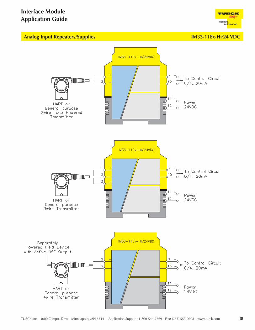
IM33-11Ex-Hi/24 VDC Analog Input Repeaters/Supplies
This 1 channel intrinsically safe interface will power a 2 or 3-wire HART transmitter or a separately powered field device. Itwill retransmit the 0/20 mA or 4/20 mA signal from a hazardous area, and repeat the signal in the non-hazardous area as a0/20 mA or 4/20 mA signal reflecting the hazardous area input. The device will also accept a sourced 0/20 mA or 4/20 mAsignal from a separately powered field device and repeat this signal in the non-hazardous area. It will drive a non-hazardousarea load of up to 500 Ω.
Due to the "1:1" transmission characteristic, open circuit or short circuit conditions can be indicated by a 0 mA or 22.5 mAreading indicating the condition for alarm implementation.
HART or conventional transmitters can be accommodated by this device with bi-directional communications of digitalinformation with HART field devices.
Functional Description:
• 1 channel HART or "IS" compatible Analog Input
• 2, 3 or 4-wire configurations for sinking or sourcing field devices
• Constant field voltage
• Short-circuit protected field circuit
• Over/under current indication of 0 or 22.5 mA
• SIL 2 rated
Features:
Inputs: Hazardous Area Outputs: Non-Hazardous Area
Supply Voltage - (19-29 VDC)
Input Resistance . . . . . . 250 ΩOperating Characteristics:Voltage. . . . . . . . . . . 17 V @ 20 mACurrent . . . . . . . . . . 0-22 mAShort-circuit Current (short-term) 60 mA (for 50 ms)
0/4-20 mA
Load . . . . . . . . . . . . ≤500 ΩOpen-circuit Indication . . 0 mAClosed-circuit Indication . . ≥22.5 mA
Electrical Parameters:
For entity parameters see control drawings on pages 86-91.
Pin # Terminal Function
1 (+) 2-wire or 3-wire Field Power
2 (+) 2-wire or 3-wire Field Power
3 (-) Field Power for 2,3 Wire Device
4 N/C
5 N/C
6 N/C
7 (+) 4/20 mA Non-Hazardous Area Output
8 N/C
9 N/C
10 (-) 4/20 mA Non-Hazardous Area Output
11 Module Power (+) or AC
12 Module Power (-) or AC
TURCK Inc. 3000 Campus Drive Minneapolis, MN 55441 Application Support: 1-800-544-7769 Fax: (763) 553-0708 www.turck.com 48
Interface ModuleApplication Guide
Analog Input Repeaters/Supplies IM33-11Ex-Hi/24 VDC

49 TURCK Inc. 3000 Campus Drive Minneapolis, MN 55441 Application Support: 1-800-544-7769 Fax: (763) 553-0708 www.turck.com
TURCKInterface Technology
IM33-12Ex-Hi/24 VDC Analog Input Repeaters/Supplies
This 1 channel intrinsically safe interface will power a 2 or 3-wire HART transmitter or a separately powered field device andretransmit the 0/20 mA or 4/20 mA from a hazardous area and repeat the signal in the non-hazardous area as two 0/20 mAor 4/20 mA signals reflecting the hazardous area input. The device will also accept a sourced 0/20 mA or 4/20 mA signalfrom a separately powered field device and repeat this signal as two non-hazardous area signal. It will drive two separatenon-hazardous area loads of up to 500 Ω each.
Due to the "1:1" transmission characteristic, open-circuit or short-circuit conditions can be indicated by a 0 mA or 22.5 mAreading indicating the condition for alarm implementation.
Functional Description:
• 1 channel HART or "IS" compatible analog inputs
• 2, 3, or 4-wire configurations for sinking or sourcing field devices in any combination
• 2 independent 0/4-20 mA outputs reflecting a single hazardous area input
• Constant field voltage
• Short-circuit protected field circuits
• Over/under current indication of 0 or 22.5 mA
• SIL 2 rated
Features:
Inputs: Hazardous Area Outputs: Non-Hazardous Area
Supply Voltage - (19-29 VDC)
Input Resistance . . . . . . 250 ΩOperating Characteristics:Voltage. . . . . . . . . . . 17 V @ 20 mACurrent . . . . . . . . . . 0-22 mAShort-circuit Current (short-term) 60 mA (for 50 ms)
0/4-20 mA
Load . . . . . . . . . . . . ≤500 ΩOpen-circuit Indication . . 0 mAClosed-circuit Indication . . ≥22.5 mA
Electrical Parameters:
For entity parameters see control drawings on pages 86-91.
Pin # Terminal Function
1 (+) 2-wire or 3-wire Field Power
2 4/20 mA Input from Field Device
3 (-) Field Power for 2, 3-wire Device
4 N/C
5 N/C
6 N/C
7 (+) 4/20 mA Non-Hazardous Area Output
8 (+) 4/20 mA Non-Hazardous Area Output
9 (-) 4/20 mA Non-Hazardous Area Output
10 (-) 4/20 mA Non-Hazardous Area Output
11 Module Power (+) or AC
12 Module Power (-) or AC

TURCK Inc. 3000 Campus Drive Minneapolis, MN 55441 Application Support: 1-800-544-7769 Fax: (763) 553-0708 www.turck.com 50
Interface ModuleApplication Guide
Analog Input Repeaters/Supplies IM33-12Ex-Hi/24 VDC

51 TURCK Inc. 3000 Campus Drive Minneapolis, MN 55441 Application Support: 1-800-544-7769 Fax: (763) 553-0708 www.turck.com
TURCKInterface Technology
IM33-22Ex-Hi/24 VDC Analog Input Repeaters/Supplies
This 2 channel intrinsically safe interface will power two separate 2 or 3-wire HART Transmitters or separately powered fielddevices or any combination of these devices and retransmit the 0/20 mA or 4/20 mA from a hazardous area and repeat thesignal in the non-hazardous area as two separate 0/20 mA or 4/20 mA signals reflecting the hazardous area input. Thedevice will also accept two separate sourced 0/20 mA or 4/20 mA signals from separately powered field devices and repeatthese signals as two non-hazardous area signals. It will drive two separate non hazardous-area loads of up to 500 Ω each.
Due to the "1:1" transmission characteristic, open circuit or short-circuit conditions can be indicated by a 0 mA or 22.5 mAreading indicating the condition for alarm implementation.
HART or conventional "IS" transmitters can be accommodated by this device with bi-directional communications of digitalinformation with HART field devices.
Functional Description:
• 2 independent channel HART or "IS" compatible analog Inputs
• 2, 3, or 4-wire configurations for sinking or sourcing field devices in any combination
• Constant field voltage for each channel
• Short-circuit protected field circuits
• Over/under current indication of 0 or 22.5 mA
• SIL 2 rated
Features:
Inputs: Hazardous Area Outputs: Non-Hazardous Area
Supply Voltage - (19-29 VDC)
Input Resistance . . . . . . 250 ΩOperating Characteristics:Voltage. . . . . . . . . . . 17 V @ 20 mACurrent . . . . . . . . . . 0-22 mAShort-circuit Current (short-term) 60 mA (for 50 ms)
0/4-20 mA
Load . . . . . . . . . . . . ≤500 ΩOpen-circuit Indication . . 0 mAClosed-circuit Indication . . ≥22.5 mA
Electrical Parameters:
For entity parameters see control drawings on pages 86-91.
Pin # Terminal Function
1 (+) 2-wire or 3-wire Field Power
2 4/20 mA Input from Field Device
3 (-) Field Power for 2, 3-wire Device
4 (+) 2-wire or 3-wire Field Power
5 4/20 mA Input from Field Device
6 (-) Field Power for 2,3-wire Device
7 (+) 4/20 mA Non-Hazardous Area Output
8 (+) 4/20 mA Non-Hazardous Area Output
9 (-) 4/20 mA Non-Hazardous Area Output
10 (-) 4/20 mA Non-Hazardous Area Output
11 Module Power (+) or AC
12 Module Power (-) or AC

TURCK Inc. 3000 Campus Drive Minneapolis, MN 55441 Application Support: 1-800-544-7769 Fax: (763) 553-0708 www.turck.com 52
Interface ModuleApplication Guide
Analog Input Repeaters/Supplies IM33-22Ex-Hi/24 VDC
53 TURCK Inc. 3000 Campus Drive Minneapolis, MN 55441 Application Support: 1-800-544-7769 Fax: (763) 553-0708 www.turck.com
TURCKInterface Technology
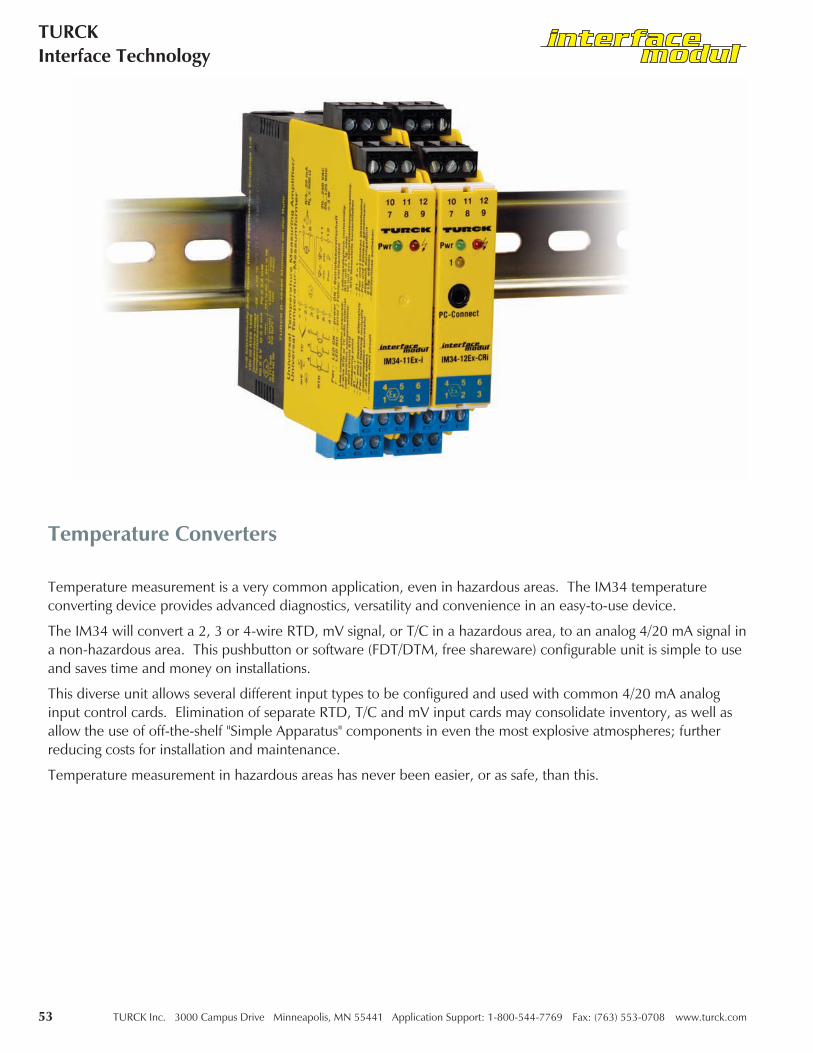
Temperature Converters
Temperature measurement is a very common application, even in hazardous areas. The IM34 temperatureconverting device provides advanced diagnostics, versatility and convenience in an easy-to-use device.
The IM34 will convert a 2, 3 or 4-wire RTD, mV signal, or T/C in a hazardous area, to an analog 4/20 mA signal ina non-hazardous area. This pushbutton or software (FDT/DTM, free shareware) configurable unit is simple to useand saves time and money on installations.
This diverse unit allows several different input types to be configured and used with common 4/20 mA analoginput control cards. Elimination of separate RTD, T/C and mV input cards may consolidate inventory, as well asallow the use of off-the-shelf "Simple Apparatus" components in even the most explosive atmospheres; furtherreducing costs for installation and maintenance.
Temperature measurement in hazardous areas has never been easier, or as safe, than this.

TURCK Inc. 3000 Campus Drive Minneapolis, MN 55441 Application Support: 1-800-544-7769 Fax: (763) 553-0708 www.turck.com 54
Interface ModuleApplication Guide
Part Number Keys are to assist in IDENTIFICATION ONLY. Consult Factory for catalog items not identified.
IM34-12Ex-CRiInterface ModuleTemperature ConverterSingle Channel InputTwo Non-Hazardous Area Current OutputsIntrinsically Safe Associated ApparatusComputer or Remote ConfigurationAlarm ContactsNon-Hazardous Current OutputUniversal Voltage Input
Extension Examples:
Temperature Converters Part Number Key
Interface Module
34 = Temperature Converter
Function Group
Number of Hazardous Area Inputs
IM 34 - 1 2 Ex - CRi
Number of Non-Hazardous Area Outputs
Intrinsically Safe Associated Apparatus
C = Configuration TypeR = Special Functionsi = Safe Area Current Output(Blank) = Universal Input Voltage

55 TURCK Inc. 3000 Campus Drive Minneapolis, MN 55441 Application Support: 1-800-544-7769 Fax: (763) 553-0708 www.turck.com
TURCKInterface Technology
IM34-11Ex-I Temperature Converters
This single channel device is designed to provide an analog 4/20 mA signal to a control system that is converted from anRTD, T/C, or mV signal in a hazardous area.
The measuring range and device functions are set via rotary switches or slide switches on the side of the device.
Functional Description:
• 1 channel temperature input
• Accepts 2, 3, or 4-wire RTD's, T/C's or mV
• Switch configurable by user
• Temperature range adjustable
• Over/under current indication of 0 or 22 mA
• Internal or external CJC configurable
Features:
Inputs: Hazardous Area Outputs: Non-Hazardous Area
Supply Voltage - (20-250 VAC or 20-125 VDC)
2, 3 or 4-wire 100 Ω Ni or Pt RTD's
Range -200°K to +800°K (Pt100), -60°K to +250°K (Ni100)
T/C's B, E, J, K, N, R, S, T
Low Voltage -160 mV to +160 mV
Resistor current approx. 200 microamps
0/4-20 mA (Load 600 Ω max)Relay: 250 VAC/120 VDC, 2A500 VA/60 W 10Hz
Electrical Parameters:
For entity parameters see control drawings on pages 86-91.

TURCK Inc. 3000 Campus Drive Minneapolis, MN 55441 Application Support: 1-800-544-7769 Fax: (763) 553-0708 www.turck.com 56
Interface ModuleApplication Guide
Temperature Converters IM34-11Ex-i
Pin # Terminal Function
1 (+) T/C or mV Input
2 (-) T/C or mV Input
3 3 or 4-wire RTD Connection
4 4-wire RTD Connection
5 2, 3 or 4-wire RTD Connection
6 2, 3 or 4-wire RTD Connection
7 (+) 0/4-20 mA Output
8 (-) 0/4-20 mA Output
9 No Connection
10 No Connection
11 Module Power (+) or AC
12 Module Power (-) or AC

57 TURCK Inc. 3000 Campus Drive Minneapolis, MN 55441 Application Support: 1-800-544-7769 Fax: (763) 553-0708 www.turck.com
TURCKInterface Technology
IM34-12Ex-Ri Temperature Converters
This single channel device is designed to provide an analog 4/20 mA signal to a control system that is converted from anRTD, T/C, or mV signal in a hazardous area.
This device has the added function of a relay output that can be used for under/over range conditions or to monitor a limitvalue.
The measuring range and device functions are set via rotary switches or slide switches on the side of the device.
Functional Description:
• 1 channel temperature input
• Accepts 2, 3, or 4-wire RTD's, T/C's or mV
• Switch configurable by user
• Temperature range adjustable
• Configurable limit value relay output
• Over/under current indication of 0 or 22 mA
• Internal or external CJC configurable
Features:
Inputs: Hazardous Area Outputs: Non-Hazardous Area
Supply Voltage - (20-250 VAC or 20-125 VDC)
2, 3 or 4-wire 100 Ω Ni or Pt RTD's
Range -200°K to +800°K (Pt100), -60°K to +250°K (Ni100)
T/C's B, E, J, K, N, R, S, T
Low Voltage -160 mV to +160 mV
Resistor current approx. 200 microamps
0/4-20 mA (Load 600 Ω max)Relay: 250 VAC/120 VDC, 2A500 VA/60 W 10Hz
Electrical Parameters:
For entity parameters see control drawings on pages 86-91.

TURCK Inc. 3000 Campus Drive Minneapolis, MN 55441 Application Support: 1-800-544-7769 Fax: (763) 553-0708 www.turck.com 58
Interface ModuleApplication Guide
Temperature Converters IM34-12Ex-Ri
Pin # Terminal Function
1 (+) T/C or mV Input
2 (-) T/C or mV Input
3 3 or 4-wire RTD Connection
4 4-wire RTD Connection
5 2, 3 or 4-wire RTD Connection
6 2, 3 or 4-wire RTD Connection
7 (+) 0/4-20 mA Output
8 (-) 0/4-20 mA Output
9 Alarm Contact
10 Alarm Contact
11 Module Power (+) or AC
12 Module Power (-) or AC

59 TURCK Inc. 3000 Campus Drive Minneapolis, MN 55441 Application Support: 1-800-544-7769 Fax: (763) 553-0708 www.turck.com
TURCKInterface Technology
IM34-11Ex-Ci Temperature Converters
This single channel device is designed to provide an analog 4/20 mA signal to a control system that is converted from anRTD, T/C or mV signal in a hazardous area.
This device is software configurable using the PACTware software tool and a configuration cable that allows configuration tobe achieved through your laptop or PC.
Functional Description:
• 1 channel temperature input
• Accepts 2, 3 or 4-wire RTD's, T/C's or mV
• Software configurable by user via PC using PACTware with software tool "Device Type Manager" (DTM)
• Temperature range adjustable
• Over/under current indication of 0 or 22 mA
• Internal or external CJC configurable
Features:
Inputs: Hazardous Area Outputs: Non-Hazardous Area
Supply Voltage - (20-250 VAC or 20-125 VDC)
2, 3 or 4-wire 100 Ω Ni or Pt RTD's
Range -200°K to +800°K (Pt100), -60°K to +250°K (Ni100)
T/C's B, E, J, K, N, R, S, T
Low Voltage -160 mV to +160 mV
Resistor current approx. 200 microamps
0/4-20 mA (Load 600 Ω max)
Electrical Parameters:
For entity parameters see control drawings on pages 86-91.

TURCK Inc. 3000 Campus Drive Minneapolis, MN 55441 Application Support: 1-800-544-7769 Fax: (763) 553-0708 www.turck.com 60
Interface ModuleApplication Guide
Temperature Converters IM34-11Ex-Ci
Pin # Terminal Function
1 (+) T/C or mV Input
2 (-) T/C or mV Input
3 3 or 4-wire RTD Connection
4 4-wire RTD Connection
5 2, 3 or 4-wire RTD Connection
6 2, 3 or 4-wire RTD Connection
7 (+) 0/4-20 mA Output
8 (-) 0/4-20 mA Output
9 No Connection
10 No Connection
11 Module Power (+) or AC
12 Module Power (-) or AC
Prog Port Top of Unit to PC

61 TURCK Inc. 3000 Campus Drive Minneapolis, MN 55441 Application Support: 1-800-544-7769 Fax: (763) 553-0708 www.turck.com
TURCKInterface Technology
IM34-12Ex-CRi Temperature Converters
This single channel device is designed to provide an analog 4/20 mA signal to a control system that is converted from anRTD, T/C or mV signal in a hazardous area.
This device is software configurable using the PACTware software tool and a configuration cable that allows configuration tobe achieved through your laptop or PC.
This device has the added function of a relay output that can be used for under/over range conditions or to monitor a limitvalue.
Functional Description:
• 1 channel temperature input
• Accepts 2, 3 or 4-wire RTD's, T/C's or mV
• Software configurable by user via PC using PACTware with software tool "Device Type Manager" (DTM)
• Temperature range adjustable
• Configurable limit value relay output
• Over/under current indication of 0 or 22 mA
• Internal or external CJC configurable
Features:
Inputs: Hazardous Area Outputs: Non-Hazardous Area
Supply Voltage - (20-250 VAC or 20-125 VDC)
2, 3 or 4-wire 100 Ω Ni or Pt RTD's
Range -200°K to +800°K (Pt100), -60°K to +250°K (Ni100)
T/C's B, E, J, K, N, R, S, T
Low Voltage -160 mV to +160 mV
Resistor current approx. 200 microamps
0/4-20 mA (Load 600 Ω max)Relay: 250 VAC/120 VDC, 2A500 VA/60 W 10Hz
Electrical Parameters:
For entity parameters see control drawings on pages 86-91.

TURCK Inc. 3000 Campus Drive Minneapolis, MN 55441 Application Support: 1-800-544-7769 Fax: (763) 553-0708 www.turck.com 62
Interface ModuleApplication Guide
Temperature Converters IM34-12Ex-CRi
Pin # Terminal Function
1 (+) T/C or mV Input
2 (-) T/C or mV Input
3 3 or 4-wire RTD Connection
4 4-Wire RTD Connection
5 2, 3 or 4-wire RTD Connection
6 2, 3 or 4-wire RTD Connection
7 (+) 0/4-20 mA Output
8 (-) 0/4-20 mA Output
9 Alarm Contact
10 Alarm Contact
11 Module Power (+) or AC
12 Module Power (-) or AC
Prog Port Top of Unit to PC

63 TURCK Inc. 3000 Campus Drive Minneapolis, MN 55441 Application Support: 1-800-544-7769 Fax: (763) 553-0708 www.turck.com
TURCKInterface Technology
Short Description
• Inputs for Ni100 or Pt100 acc. to IEC 751, thermoelements acc.to IEC 584 and for low voltages (mV range)
• Intrinsically safe input circuit [EEx ia] IIC
• Area of application acc. to ATEX: II (1) GD
• Wire-break monitoring
• Short-circuit monitoring of Pt100 or Ni100 components
• Galvanic isolation between input and output circuits and supply
• Analogue current output 0/4-20 mA
• Limit value relay (IM34-12Ex-Ri only)
• Temperature linear conversion
• Device configuration on side of housing
• Housing with coded and removeable terminal blocks
Terminal Configuration
Intrinsically safe inputs at terminals 1-6
1, 2 Thermoelement and mV input
3-6 Ni100 or Pt100 input
7, 8 Analogue current output
9,10 Limit value relay (IM34-12Ex-Ri only)
11,12 Supply voltage connection
20-250 VAC/20-125 VDC, ≤3 W
Connection via flat screw terminals with self-lifting pressure plates,connection profile ≤1 x 2.5 mm2, 2 x 1.5 mm2 or 2 x 1.0 mm2 withwire sleeves.
LED Indications
Pwr green power on (1)
red error (2)
1 yellow relay energised (3)(IM34-12Ex-Ri only)
Attention: Status indications, see table on page 64.
Adjustments
The device settings are accomplished with 4 rotary switches and 10slide switches (IM34-12Ex-Ri:7 rotary switches and 13 slideswitches) located on the right side of the housing.
• High Temperature Value TH: the upper temperature rangevalue according to an output current of 20 mA is set with thetwo rotary switches (1, 2). Rotary switch 2 serves to settemperature values in increments of a hundred degrees celsius.Switch 1 serves to set the temperature in steps of ten degrees.Thus, the temperature values can be set in steps of 10 K.(Example for switch position: 53 ⇒ 530°C). If the slide switchS6 is in position 1, the temperature range is automaticallyincreased by a 1000°C to 1000-1990°C. Add a 1000°C to thetemperatue value adjusted with rotary switches 1 and 2.(Examples for switch position: 53 ⇒ 1530°C; 00 ⇒ 1000°C).
• Low Temperature Value TL : the two rotary switches (3, 4)serve to set the temperature which accords to an output currentof 0 or 4 mA (determined by slide switch S8). If slide switch S5is in position 1, rotary switch number 4 is used to adjust thetemperature in hundreds, while switch 3 adjusts the tens place.Adjustment takes place in a temperature range of 0 to +990°Cin increments of 10 K (e.g. rotary switch setting 23 accords to atemperature of 230°C). If slide switch S5 is in position 0, rotaryswitch 4 adjusts the negative tens places and rotary switch 3adjusts the ones. Adjustments are possible in a temperaturerange of -100 to -1°C in increments of 1 K. (Examples for rotaryswitch position: 23 ⇒ -23°C; 00 ⇒ -100 °C).
• Switching Threshold for Relay(IM34-12Ex-Ri only)Rotary switch 5 = hundred degree valuesRotary switch 6 = ten degree valuesRotary switch 7 = one degree valuesS11 and S12 = 1: add 1000°C to the adjusted value. S11 = 0:the adjusted value is negative. The output mode is adjustedwith S13.
Temperature Converters
IM34-11Ex-i
IM34-12Ex-Ri

Switch Position Functions of slide switches S1-S4:The 4 switches serve to select the following functions:S1 S2 S3 S4
0 0 0 0 Thermoelement Type B (IEC 584)
0 0 0 1 Type E
0 0 1 0 Type J
0 0 1 1 Type K
0 1 0 0 Type N
0 1 0 1 Type R
0 1 1 0 Type S
0 1 1 1 Type T (IEC 584)
1 0 0 0 Type L (DIN 43710)
1 0 1 0 Voltage input: the input for thermoelements can be used for linear conversion of low voltages from -100 to+160 mV. In this case the rotary switches are used to adjust mV values while the slides switches operatewith different range indications:
S5 = 0: -100 to -1 mV orS5 = 1: 0 to +99 mV for the lower range;S6 = 0: 0 to +99 mV orS6 = 1: +100 to +160 mV for the upper range;
1 1 0 0 Pt100 or Ni100 components with 4-wire connection;
1 1 0 1 Pt100 or Ni100 components with 3-wire connection, observe bridge;
1 1 1 0 Pt100 or Ni100 components with 2-wire connection, observe bridge;
1 1 1 1 Line compensation: when using 2-wire connections, the line length resistance must be adjusted. Linecompensation is also necessary when using thermo-elements with an external cold junction. For this it isnecessary to short-circuit the measuring point and to select the code for line compensation as shown on theleft. The Pwr and the LED flash alternately. Successfull line compensation is indicated by mutual flashingof both LEDs. Please select a different function and remove the short-circuit.
TURCK Inc. 3000 Campus Drive Minneapolis, MN 55441 Application Support: 1-800-544-7769 Fax: (763) 553-0708 www.turck.com 64
Interface ModuleApplication Guide
Temperature Converters
IM34-11Ex-i
IM34-12Ex-Ri

65 TURCK Inc. 3000 Campus Drive Minneapolis, MN 55441 Application Support: 1-800-544-7769 Fax: (763) 553-0708 www.turck.com
TURCKInterface Technology
Temperature Converters
Mounting and Installation
The connected apparatus (Ni100/Pt100, thermoelements) mustmeet the requirements for use in explosion hazardous areas(EN60079-14). The device is suited for snap-on clamps for hat railmounting (EN 50022) or for screw panel mounting. Devices of thesame type may be mounted directly next to each other. It must beensured that heat is conducted away from the device. Mountingand installation must be carried out in accordance with theapplicable regulations. The removeable terminal blocks are codedand may only be plugged into the designated sockets. The codingsystem may not be altered or damaged. The device must beprotected against dust, dirt, moisture and other environmentalinfluences as well as against strong electro-magnetic emissions. Itshould also be protected against the risks of mechanical damaging,unauthorised access and incidental contact. All installations mustbe carried out observing the regulations of EMC protection.
General information on use of devices with "IS" circuits
This device is equipped with circuits featuring protection type"intrinsic safety" for explosion protection per EN 50020 at terminals1-6 which are marked in blue. The intrinsically safe circuits areapproved by the authorised bodies for use in those countries towhich the approval applies.
For correct usage in explosion hazardous areas it is required toobserve and follow the national regulations and directivesstrictly. Following please find some guidelines referring to theframework directive of the European Union 94/9/EC (ATEX 100a).
This device is classified as an associated apparatus which isequipped with intrinsically safe and non-intrinsically safe circuits.Therefore it may not be installed in explosion hazardous areas. It ispermitted to connect intrinsically safe equipment to the intrinsicallysafe connections of this device, provided the equipment complieswith the regulations applying to use in the respective zone of theexplosion hazardous area. When interconnecting devices within
Functions of slide switches S5-S10 (IM34-12Ex-Ri: S5-S13):The following functions can be selected with the switches:
• S5 Lower range selection: selection of temperature range of lowtemp. valueTLS5 = 0: -100 to -1°CS5 = 1: 0 to +990°C
• S6 Upper range selection: selection of temperature range ofhigh temp. value TH:S6 = 0: 0 to +990°CS6 = 1: +1000 to +1990°C
• S7 output current during an error condition:If an input circuit error is detected, theoutput current is asfollowsS7 = 0: 0 mAS7 = 1: >22 mA
• S8 output current range:S8 = 0: 0-20 mAS8 = 1: 4-20 mA
• S9 Reference point compensation: when using thermolements,reference point compensation is carried out as follows:- externally via 2-wire Ni100 or Pt100 in S9 = 0 or- internally: S9 = 1
With internal reference point compensation, care must betaken that heat is conducted away from the housing. Heataccumulation can corrupt measuring data.
• S10 resistor type: indication of the connected resistor type:S10 = 0: Pt100S10 = 1: Ni100
With a voltage input or in case of thermoelement operation, thetype of resistor does not have to be adjusted.
Referring to IM34-12Ex-Ri only:
• S11, S12 and S13 Selection of switching threshold for limitvalue relay:S11 = 0: -100 to -1°CS11 = 1: >0°C
Only if S11 = 1S12 = 0: 0 to +999°CS12 = 1: +1000 to +1990°CS13 Output performance of relay:S13 = 0: relay energised, if measuring value > switchingthresholdS13 = 1: relay energised, if measuring value < switchingthreshold
IM34-11Ex-i
IM34-12Ex-Ri

TURCK Inc. 3000 Campus Drive Minneapolis, MN 55441 Application Support: 1-800-544-7769 Fax: (763) 553-0708 www.turck.com 66
Interface ModuleApplication Guide
Temperature Converters
IM34-11Ex-i
IM34-12Ex-Ri
Short Description
• Inputs for Ni100 or Pt100 acc. to IEC 751, thermo-elementsacc. to IEC 584 and for low voltages (mV range)
• Intrinsically safe input circuit EEx ia
• Area of application acc. to ATEX: II (1) GD
• Wire-break monitoring
• Short-circuit monitoring only of Pt100 or Ni100 components
• Galvanic isolation between input and output circuits and supply
• Analogue current output 0/4-20 mA
• Voltage proof up to 4 kV (IM34-11Ex-Ci/K51 only)
• Fast temperature measurement from a temperature gradient of200 ìV/s (IM34-11Ex-Ci/K60 only)
• Limit value relay (IM34-12Ex-CRi only)
• Temperature linear conversion
• Parameterisation via PC via programming adapter IM-PROG (tobe ordered additionally – ident-no.: 6890422)
• Housing with coded and removeable terminal blocks
• Simulation of outputs
Terminal Configuration
Intrinsically safe inputs at terminals 1–6
1, 2 thermoelement and mV input3 – 6 Ni100 or Pt100 input7, 8 analog current output (0/4-20 mA)9, 10 Limit value relay (IM34-12Ex-CRi only)11,12 supply voltage connection
20-250 VAC/20-125 VDC, <3 W
Connection via lifting cages with captive screws, connectionprofile:≤1 x 2.5 mm2, 2 x 1.5 mm2 or 2 x 1 mm2 with wire sleeves
LED Indications
Pwr green power on
red error
1 yellow relay energised(IM34-12Ex-CRi only)
Attention: Status Indications, see table on page 67.
such an assembly it is required to keep and provide a proof ofintrinsic safety (EN 60079-14). Once that intrinsically safe circuitshave been connected to the non-intrinsically safe circuit, it is notpermitted to use the device subsequently as intrinsically safeequipment.
The governing regulations cover installation of intrinsically safecircuits, mounting to external connections, cable characteristics andcable installation. Cables and terminals with intrinsically safecircuits must be marked and separated from non-intrinsically safecircuits or feature appropriate isolation (EN 60079-14). It isrequired to observe the specified clearances between theintrinsically safe connections of this device and the earthedcomponents and connections of other devices. The approvalexpires if the device is repaired, modified or opened by a personother than the manufacturer or an expert, unless the devicespecificinstruction manual explicitly permits such interventions.
Visible damages of the device's housing (e. g. black-browndiscolouration due to heat accumulation, perforation or
deformation) indicate a serious error and the device must beturned off immediately. When using associated apparatus it isrequired to check the connected intrinsically safe equipment too.This inspection may only be carried out by an expert or themanufacturer. Operation of the device must conform to the dataprinted on the side of the housing.
Prior to initial set-up or after every alteration of the interconnectionassembly it must be assured that the relevant regulations, directivesand framework regulations are observed, that operation is errorfreeand that all safety regulations are fulfilled. Mounting andconnection of the device should only be carried out by qualifiedand trained staff familiar with the relevant national andinternational regulations of explosion protection.
The most important data from the EC type examinationcertificate are listed overleaf. All valid national and internationalapprovals covering TURCK devices can be downloaded from ourwebsite www.turck.com. Further information can be provided onrequest.

67 TURCK Inc. 3000 Campus Drive Minneapolis, MN 55441 Application Support: 1-800-544-7769 Fax: (763) 553-0708 www.turck.com
TURCKInterface Technology
Temperature Converters
IM34-11Ex-i
IM34-12Ex-Ri
LED Pwr LED Only IM34-12Ex-CRi Description
The values agree with the switch-on phase in %0=0%, 10=10%, 50=50%, 100=100%
Output of error current,moreover relay is de-energized.
100 0 − Operation
100 10 • Input error
10 100 • Software error
0 100 • Hardware error
100 50 • Measuring span too short
100 50 − Thermoelements/Measuring range/Switching threshold outsidethe operating range of the RTD or thermo-element
50 50 • Line compensation (LEDs flashing alternatingly)
50 50 • Line compensation finished
100 50 • Line compensation not correct
50 0 − Current ouput and limit value relay in simultaneous operation
Status Indications

TURCK Inc. 3000 Campus Drive Minneapolis, MN 55441 Application Support: 1-800-544-7769 Fax: (763) 553-0708 www.turck.com 68
Interface ModuleApplication Guide
Parameterisation and Adjustments
The IM34... is parameterised and adjusted via the Device TypeManager (see also "PACTware™ and devices DTM softwareinstallation"). The TURCK adapter IM-PROG is needed to establishthe connection between the device and your PC.
For this it is necessary to connect the 3.5 mm connector to themeasuring amplifier (PCConnect) and the RS232 connector to theserial interface of your PC. The following settings are available asan entry or numerical setting via the DTM:
• ModeSelection of the connection element: Pt/Ni100,thermo-element, mV input and selection of line compensation.The following settings depend on the selections made in the"Mode" menu:
– Thermo-elementType selection: E, J, K, N, R, S, T, L, B
– Connection Mode of Temperature Resistor2, 3 or 4-wire connection technology
– Measuring RangeThe measuring range is composed of the lower and uppertemperature value. After selecting the connecting type, themeasuring range is indicated in the lower section of the DTM.These indications accord to the adjusted analogue output signalof 0/4-20 mA. The lower temperature depends on the type ofthermoelement/temperature resistor and accords to an outputsignal of 0/4 mA. The upper limit temperature also depends onthe type of thermo-element/temperature resistor. The adjustedupper limit temperature accords to an analogue output signal of20 mA.
– Output SignalThe selection comprises 0-20 mA, 4-20 mA signals. Theadjusted values correspond to the adjusted lower and upperlimit temperatures.
– Line CompensationIn case of 2-wire connections, the resistor can be adapted to theconnection cable. For this it is necessary to short the measuringpoint.
The LEDs Pwr and flash alternately. If they start flashingmutually line compensation has been carried out. Continue byselecting another function and removing the short-circuit. If theLED continues to flash, line compensation has not beenaccomplished succesfully. Line compensation must also becarried out if thermo-elements with external cold junction areused.
– Error CurrentEither 0 mA or >22 mA
– Switching Threshold (IM34-12Ex-CRi only)Entry of a temperature value or a low voltage value at which thelimit value relay is activated.
Mounting and Installation
The connected apparatus (Ni100/Pt100, thermo-elements) mustmeet the requirements for use in explosion hazardous areas (EN60079-14). The device is suited for snap-on clamps for hat railmounting (EN 50022) or for screw panel mounting. Devices of thesame type may be mounted directly next to each other. It must beensured that heat is conducted away from the device. Mountingand installation must be carried out in accordance with theapplicable regulations. The operator is responsible for compliancewith the regulations. The removeable terminal blocks are codedand may only be plugged into the designated sockets. The codingsystem may not be altered or damaged. The device must beprotected against dust, dirt, moisture and other environmentalinfluences as well as against strong electromagnetic emissions. Itshould also be protected against the risks of mechanical damaging,unauthorised access and incidental contact. All installations must becarried out observing the regulations of EMC protection.
Temperature Converters
IM34-11Ex-i
IM34-12Ex-Ri

69 TURCK Inc. 3000 Campus Drive Minneapolis, MN 55441 Application Support: 1-800-544-7769 Fax: (763) 553-0708 www.turck.com
TURCKInterface Technology
Important information on use of devices with "IS" circuits
This device is equipped with circuits featuring protection typeintrinsic safety for explosion protection per EN 50020 at terminals1– 6 which are marked in blue. The intrinsically safe circuits areapproved by the authorised bodies for use in those countries towhich the approval applies.
For correct usage in explosion hazardous areas please observeand follow the national regulations and directives strictly.Following please find some guidelines referring to the frame-workdirective of the European Union 94/9/EC (ATEX 100a).
This device is classified as an associated apparatus which isequipped with intrinsically safe and nonintrinsically safe circuits.Therefore it may only be installed in the non-explosion hazardousarea in dry clean and well monitored locations. It is permitted toconnect intrinsically safe equipment to the intrinsically safeconnections of this device.
All electrical equipment must comply with the regulations applyingto use in the respective zone of the explosion hazardous area. If theintrinsically safe circuits lead into explosion hazardous areas subjectto dust hazards, i.e. zone 20 or 21, it must be ensured that thedevices which are to be connected to these circuits, meet therequirements of category 1D or 2D and feature an accordingapproval.
When interconnecting devices within such anassembly it isrequired to keep and provide a proof of intrinsic safety (EN60079-14). Once that intrinsically safe circuits have beenconnected to the non-intrinsically safe circuit, it is not permitted touse the device subsequently as intrinsically safe equipment. Thegoverning regulations cover installation of intrinsically safe circuits,mounting to external connections, cable characteristics and cable
installation. Cables and terminals with intrinsically safe circuitsmust be marked and separated from nonintrinsically safe circuits orfeature appropriate isolation (EN 60079-14). Please observe thespecified clearances between the intrinsically safe connections ofthis device and the earthed components and connections of otherdevices.
The approval expires if the device is repaired, modified or openedby a person other than the manufacturer or an expert, unless thedevice-specific instruction manual explicitly permits suchinterventions.
Visible damages of the device’s housing (e. g. blackbrowndiscolouration due to heat accumulation, perforation ordeformation) indicate a serious error and the device must beturned off immediately. When using associated apparatus it isrequired to check the connected intrinsically safe equipment too.This inspection may only be carried out by an expert or themanufacturer.
Operation of the device must conform to the data printed on theside of the housing. Prior to initial set-up or after every alterationof the interconnection assembly it must be assured that the relevantregulations, directives and framework conditions are observed, thatoperation is error-free and that all safety regulations are fulfilled.Mounting and connection of the device may only be carried out byqualified and trained staff familiar with the relevant national andinternational regulations of explosion protection.
The most important data from the EC type examinationcertificate are listed overleaf. All valid national and internationalapprovals covering TURCK devices are obtainable via the Internet(www.turck.com). Further information on explosion protection isavailable on request.
Temperature Converters
IM34-11Ex-i
IM34-12Ex-Ri

TURCK Inc. 3000 Campus Drive Minneapolis, MN 55441 Application Support: 1-800-544-7769 Fax: (763) 553-0708 www.turck.com 70
Interface ModuleApplication Guide
PACTware™ and Devices DTM Software Installation
You will require the following software components on yourcomputer for the installation of PACTware:
• PACTware software for parameterising of interfacemodules and excom ®
• DTM
These software components are available on the Internet atwww.turck.com as a free-of-charge download.
• Select the homepagewww.turck.com → Download → Software.
Your PC then requests the name of a directory at which itshould save the files on the harddrive of your computer. Thefiles are self-extracting archives, ZIP files, which extractindependently when accessed.
• Simply double click on the ZIP archive to extract the files.
• You commence extraction of the file when you click on"Extract".
The "TURCK_FILES" directory is created on the current drive(e.g. C:\). Extract both file archives: (PACTware and DTM)before you commence with the actual software installation.
1. Installation of PACTware
Now start the installation of PACTware on your computer.
• Start Windows Explorer and change over to the"TURCK_FILES\PACTware...SetupTurck\PACTware" directory.
• Start the "setup.exe" file located there.
Follow the self-explanatory instructions displayed by theinstallation program and complete the installation.
2. Installation of the HART ® Communication Driver
After the installation of PACTware has been successfullycompleted, the HART communication driver must now beinstalled.
Start the "setup.exe" file located at "TURCK_FILES\...Dtms\Hart"
Follow the self-explanatory instructions displayed by theinstallation program and complete the installation.
3. Installing of the Devices DTM
After the installation of the HART communication driver beensuccessfully completed, the devices DTM must be installed. Adirectory has been created to reflect the DTM which you have
downloaded. The name commences with the first 4 or 5 lettersof the device type which you have selected.
• Start for example "setup.exe" in the"TURCK_FILES\IM34...Setup...\" directory in order to install thedevices DTM for the IM34.
Configuration of PACTware
Please restart your PC after installation in order to update theWindows registry. Then open PACTware and carry outconfiguration:
Make the following entries:
– User: "Administrator“– Password: "manager“Prior to parameterising a device, a project has to be created.For this, please select the device catalogue from the "View“menu or the < F3 > key. A new window with the name"Device catalogue" will open. This window contains all available"Device Type Managers - DTMs". Should a required DTM notbe listed, please click on the button "Re-initialize the devicecatalogue"
• First add the HART protocol driver from thecompany Codewrights GmbH
• Then add the DTMs from TURCK
Parameter entries for HART protocol driver parameters:
(Open the window by a double click):– Communication-Interface:
"HART Multiplexer“
– Select serial interface
– Baud rate: "9600“
Possible error sources:
– RS232 port not addressable or being used by anotherapplication, Remedy: use different port or exit the applicationcausing problems
– RS232 line too long (max. line length approx. 10 m),Remedy: shorten line
After successful installation and configuration it is now possibleto communicate with the IM34....

71 TURCK Inc. 3000 Campus Drive Minneapolis, MN 55441 Application Support: 1-800-544-7769 Fax: (763) 553-0708 www.turck.com
TURCKInterface Technology
Analog Output Isolators
Analog output isolators are for use with conventional 4/20 mA or HART smart "IS" devices are available in 1 and 2 channelversions. These devices are designed to provide a convenient way to transfer 4/20 mA signals, generated in a non-hazardousarea, to a hazardous area intrinsically safe device, such as a valve positioner or I/P device.
HART capabilities allow bi-directional communications for HART devices if this function is being utilized. The same devicesare also applicable for non-HART smart devices.
One device can be used for all applications of this type, which makes applying these devices simple. Stocking spares onlyrequires one type of unit adding to the convenience.
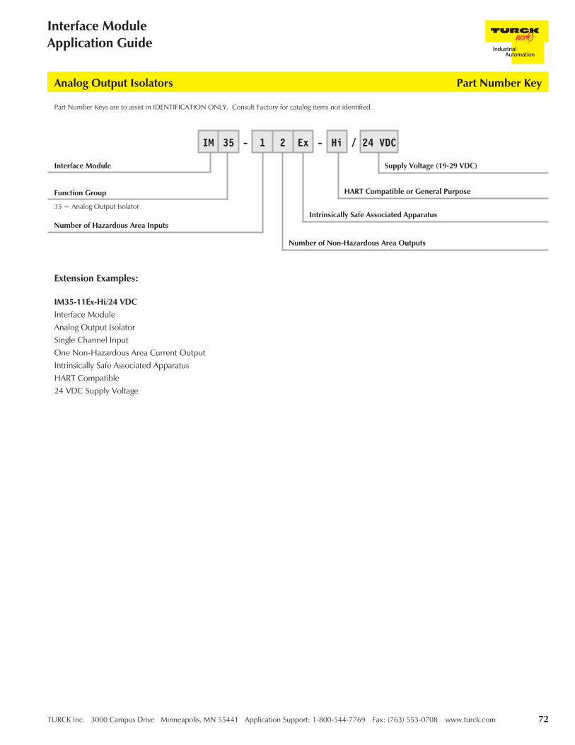
TURCK Inc. 3000 Campus Drive Minneapolis, MN 55441 Application Support: 1-800-544-7769 Fax: (763) 553-0708 www.turck.com 72
Interface ModuleApplication Guide
Part Number Keys are to assist in IDENTIFICATION ONLY. Consult Factory for catalog items not identified.
IM35-11Ex-Hi/24 VDCInterface ModuleAnalog Output IsolatorSingle Channel InputOne Non-Hazardous Area Current OutputIntrinsically Safe Associated ApparatusHART Compatible24 VDC Supply Voltage
Extension Examples:
Analog Output Isolators Part Number Key
Interface Module
35 = Analog Output Isolator
Function Group
Number of Hazardous Area Inputs
IM 35 - 1 2 Ex - Hi / 24 VDC
Supply Voltage (19-29 VDC)
Number of Non-Hazardous Area Outputs
Intrinsically Safe Associated Apparatus
HART Compatible or General Purpose

73 TURCK Inc. 3000 Campus Drive Minneapolis, MN 55441 Application Support: 1-800-544-7769 Fax: (763) 553-0708 www.turck.com
TURCKInterface Technology
IM35-11Ex-Hi/24 VDC Analog Output Isolators
This single channel device will allow a controller in a non-hazardous area to provide a 1:1 transfer of a 0/4-20 mA signal to adevice in a hazardous area. Valve controllers or I/P devices that are intrinsically safe, as well as signals that are "IS" originatingfrom another non-hazardous area, may be accommodated. Bi-directional HART communications capability is alsoincorporated.
Functional Description:
• 1 channel 0/4-20 mA current driver
• HART or non-HART compatible
• Allows bi-directional HART communications
• Facilities for non-hazardous area HART monitoring
• Linearity of less than 0.1%
• Temperature drift less than 0.01% /K
Features:
Inputs: Hazardous Area Outputs: Non-Hazardous Area
Supply Voltage (19-29 VDC)0-20 mA24 mA can be transferred max load of 430 ΩInput Resistance 110 Ω
0/4-20 mA (Load 600 Ω max.)Relay: 250 VAC/120 VDC, 2A500 VA/60 W 10Hz
Electrical Parameters:
For entity parameters see control drawings on pages 86-91.

TURCK Inc. 3000 Campus Drive Minneapolis, MN 55441 Application Support: 1-800-544-7769 Fax: (763) 553-0708 www.turck.com 74
Interface ModuleApplication Guide
Analog Output Isolators IM35-11Ex-Hi/24 VDC
Pin # Terminal Function
1 (+) 0/4-20 mA Field Output
2 (-) 0/4-20 mA Field Output
3 No Connection
4 No Connection
5 No Connection
6 No Connection
7 (+) 0/4-20 mA Non-Hazardous Area Input
8 No Connection
9 No Connection
10 (-) 0/4-20 mA Non-Hazardous Area Input
11 Module Power (+)
12 Module Power (-)

75 TURCK Inc. 3000 Campus Drive Minneapolis, MN 55441 Application Support: 1-800-544-7769 Fax: (763) 553-0708 www.turck.com
TURCKInterface Technology
IM35-22Ex-Hi/24 VDC Analog Output Isolators
This dual channel device will allow a controller in a non-hazardous area to provide a 1:1 transfer of 2 separate 0/4-20 mAsignals to two separate devices in the hazardous area. Valve controllers or I/P devices that are intrinsically safe, as well assignals that are "IS" originating from another non-hazardous area, or any combination of these signals, may beaccommodated. Bi-directional HART communications capability is also incorporated for both channels.
Functional Description:
• 2 channel 0/4-20 mA current driver
• HART or non-HART compatible
• Allows bi-directional HART communications
• Facilities for non-hazardous area HART monitoring
• Linearity of less than 0.1%
• Temperature drift less than 0.01% /K
Features:
Inputs: Hazardous Area Outputs: Non-Hazardous Area
Supply Voltage (19-29 VDC)0-20 mA24 mA can be transferred max load of 430 ΩInput Resistance 110 Ω
0/4-20 mA(Load 600 Ω max)
24 mA with a max load of 430 ΩLoad is 600 Ω max
Electrical Parameters:
For entity parameters see control drawings on pages 86-91.
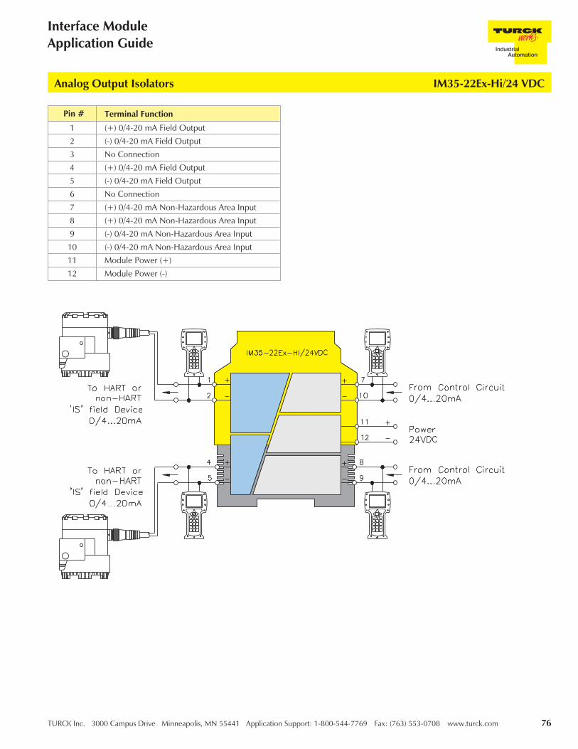
TURCK Inc. 3000 Campus Drive Minneapolis, MN 55441 Application Support: 1-800-544-7769 Fax: (763) 553-0708 www.turck.com 76
Interface ModuleApplication Guide
Analog Output Isolators IM35-22Ex-Hi/24 VDC
Pin # Terminal Function
1 (+) 0/4-20 mA Field Output
2 (-) 0/4-20 mA Field Output
3 No Connection
4 (+) 0/4-20 mA Field Output
5 (-) 0/4-20 mA Field Output
6 No Connection
7 (+) 0/4-20 mA Non-Hazardous Area Input
8 (+) 0/4-20 mA Non-Hazardous Area Input
9 (-) 0/4-20 mA Non-Hazardous Area Input
10 (-) 0/4-20 mA Non-Hazardous Area Input
11 Module Power (+)
12 Module Power (-)

77 TURCK Inc. 3000 Campus Drive Minneapolis, MN 55441 Application Support: 1-800-544-7769 Fax: (763) 553-0708 www.turck.com
TURCKInterface Technology
Solenoid Driver/Discrete Output Isolators
These loop powered "IS" interface devices provide power for "IS" solenoids in a hazardous area to be actuated from acontroller in the non-hazardous area.
The IM72 solenoid drivers are uniquely designed devices that allow them to drive the vast majority of "IS" solenoids availablein today's marketplace with a single type of interface device. Gone are the days when a wide variety of isolators wereavailable to drive specific solenoids with specific requirements. A single device will now allow you to use a single model formost applications, eliminating the need to do complicated and tedious calculations.
The design of these 1 and 2 channel devices make it extremely simple to choose the appropriate interface. Either choose a 1channel or 2 channel interface, that's all there is to it. Stock can be significantly reduced, and installation and maintenancemade easier. With a single unit for most applications, the IM72 makes choosing the appropriate interface as easy as it gets.
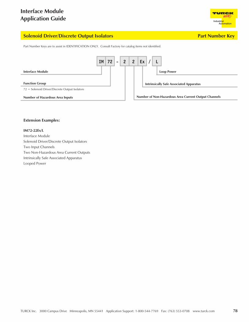
TURCK Inc. 3000 Campus Drive Minneapolis, MN 55441 Application Support: 1-800-544-7769 Fax: (763) 553-0708 www.turck.com 78
Interface ModuleApplication Guide
Part Number Keys are to assist in IDENTIFICATION ONLY. Consult Factory for catalog items not identified.
IM72-22Ex/LInterface ModuleSolenoid Driver/Discrete Output IsolatorsTwo Input ChannelsTwo Non-Hazardous Area Current OutputsIntrinsically Safe Associated ApparatusLooped Power
Extension Examples:
Solenoid Driver/Discrete Output Isolators Part Number Key
Interface Module
72 = Solenoid Driver/Discrete Output Isolators
Function Group
Number of Hazardous Area Inputs
IM 72 - 2 2 Ex / L
Loop Power
Number of Non-Hazardous Area Current Output Channels
Intrinsically Safe Associated Apparatus

79 TURCK Inc. 3000 Campus Drive Minneapolis, MN 55441 Application Support: 1-800-544-7769 Fax: (763) 553-0708 www.turck.com
TURCKInterface Technology
IM72-11Ex/L Solenoid Driver/Discrete Output Isolators
This single channel device is designed to drive the vast majority of intrinsically safe solenoids available, as well as "IS" displaysand other field devices that may require a separate "IS" power source. The unique design allows different configurations to beimplemented depending on the specific field device being used.
Loop power is applied from a non-hazardous area source directly to the non-hazardous area inputs eliminating therequirement for additional power supply connections.
Functional Description:
• 1 channel solenoid driver or "IS" supply
• Loop powered
• 2 output levels
• Switching frequency up to 500 Hz
Features:
Inputs: Hazardous Area Outputs: Non-Hazardous Area
Supply (Loop Power)Signal "OFF" . . . . . . . . <5 V
Signal "ON" . . . . . . . . 19-30 VDC
Switch-on delay . . . . . . <400 µ
In accordance with Output Curve:
U1=24 V (Pins 1 & 3) . . . U2=15 V (Pins 2 &3)
I1= 45 mA (Pins 1 &3) . . . I2=45 mA (Pins 2 & 3)
Switching Frequency . . . . <500 Hz
Electrical Parameters:
For entity parameters see control drawings on pages 86-91.
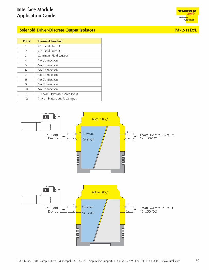
TURCK Inc. 3000 Campus Drive Minneapolis, MN 55441 Application Support: 1-800-544-7769 Fax: (763) 553-0708 www.turck.com 80
Interface ModuleApplication Guide
Solenoid Driver/Discrete Output Isolators IM72-11Ex/L
Pin # Terminal Function
1 U1 Field Output
2 U2 Field Output
3 Common Field Output
4 No Connection
5 No Connection
6 No Connection
7 No Connection
8 No Connection
9 No Connection
10 No Connection
11 (+) Non-Hazardous Area Input
12 (-) Non-Hazardous Area Input

81 TURCK Inc. 3000 Campus Drive Minneapolis, MN 55441 Application Support: 1-800-544-7769 Fax: (763) 553-0708 www.turck.com
TURCKInterface Technology
IM72-22Ex/L Solenoid Driver/Discrete Output Isolators
This dual channel device is designed to drive 2 separate intrinsically safe solenoids, "IS" displays or other field devices thatmay require a separate "IS" power source, or any combination of these devices. The unique design allows differentconfigurations to be implemented depending on the specific field device or devices being applied.
Loop power is applied from a non-hazardous area source directly to the non-hazardous area inputs of each channeleliminating the requirement for additional power supply connections.
Functional Description:
• 2 channel solenoid driver or "IS" supply
• 2 isolated loop powered circuits
• 2 output levels per channel
• Switching frequency up to 500 Hz
Features:
Inputs: Hazardous Area Outputs: Non-Hazardous Area
Supply (Loop Power)Signal "OFF" . . . . . . . . <5 V
Signal "ON" . . . . . . . . 19-30 VDC
Switch-on delay . . . . . . <400 µ
In accordance with Output Curve:
U1=24 V (Pins 1 & 3, 4 & 6)U2=15 V (Pins 2 & 3, 5 & 6)
I1= 45 mA (Pins 1 & 3, 4 & 6)I2=45 mA (Pins 2 & 3, 5 & 6)
Switching Frequency . . . . <500 Hz
Electrical Parameters:
For entity parameters see control drawings on pages 86-91.

TURCK Inc. 3000 Campus Drive Minneapolis, MN 55441 Application Support: 1-800-544-7769 Fax: (763) 553-0708 www.turck.com 82
Interface ModuleApplication Guide
Solenoid Driver/Discrete Output Isolators IM72-22Ex/L
Pin # Terminal Function
1 U1 Field Output
2 U2 Field Output
3 Common Field Output
4 U1 Field Output
5 U2 Field Output
6 Common Field Output
7 No Connection
8 (+) Non-Hazardous Area Input
9 (-) Non-Hazardous Area Input
10 No Connection
11 (+) Non-Hazardous Area Input
12 (-) Non-Hazardous Area Input

83 TURCK Inc. 3000 Campus Drive Minneapolis, MN 55441 Application Support: 1-800-544-7769 Fax: (763) 553-0708 www.turck.com
TURCKInterface Technology
IM72-22Ex/L Solenoid Driver/Discrete Output Isolators
Pin # Terminal Function
1 U1 Field Output
2 U2 Field Output
3 Common Field Output
4 U1 Field Output
5 U2 Field Output
6 Common Field Output
7 No Connection
8 (+) Non-Hazardous Area Input
9 (-) Non-Hazardous Area Input
10 No Connection
11 (+) Non-Hazardous Area Input
12 (-) Non-Hazardous Area Input
TURCK Inc. 3000 Campus Drive Minneapolis, MN 55441 Application Support: 1-800-544-7769 Fax: (763) 553-0708 www.turck.com 84
Interface ModuleApplication Guide
Notes:

85 TURCK Inc. 3000 Campus Drive Minneapolis, MN 55441 Application Support: 1-800-544-7769 Fax: (763) 553-0708 www.turck.com
TURCKInterface Technology
Part NumberIECEx Approval Number ATEX Approval Number
http://domino.iec.ch/IECEx/IECExWeb.nsf www.turck.com/IMATEX
IM1-121EX-R IECEx TUN 06.0006X PTB 00 ATEX 2033
IM1-121EX-T IECEx TUN 06.0006X PTB 00 ATEX 2033
IM1-12EX-MT IECEx TUN 06.0006X PTB 00 ATEX 2033
IM1-12EX-R IECEx TUN 06.0006X PTB 00 ATEX 2033
IM1-12EX-T IECEx TUN 06.0006X PTB 00 ATEX 2033
IM1-22EX-MT IECEx TUN 06.0006X PTB 00 ATEX 2033
IM1-22EX-R IECEx TUN 06.0006X PTB 00 ATEX 2033
IM1-22EX-T IECEx TUN 06.0006X PTB 00 ATEX 2033
IM1-451EX-R IECEx TUN 06.0007X PTB 00 ATEX 2033
IM1-451EX-T IECEx TUN 06.0007X PTB 00 ATEX 2033
IM12-22EX-R IECEx TUN 06.0006X PTB 00 ATEX 2033
IM31-11EX-I IECEx TUN 06.0006X TÜV 04 ATEX 2679
IM31-11EX-U IECEx TUN 06.0006X TÜV 04 ATEX 2679
IM31-12EX-I IECEx TUN 06.0006X TÜV 04 ATEX 2679
IM31-22EX-I IECEx TUN 06.0006X TÜV 04 ATEX 2679
IM31-22EX-U IECEx TUN 06.0006X TÜV 04 ATEX 2679
IM33-11EX-HI/24VDC IECEx TUN 06.0001X TÜV 00 ATEX 1595
IM33-12EX-HI/24VDC IECEx TUN 06.0001X TÜV 00 ATEX 1595
IM33-22EX-HI/24VDC IECEx TUN 06.0001X TÜV 00 ATEX 1595
IM34-11EX-CI IECEx TUN 06.0010X TÜV 02 ATEX 1898
IM34-11EX-I IECEx TUN 06.0010X TÜV 02 ATEX 1898
IM34-12EX-CRI IECEx TUN 06.0010X TÜV 02 ATEX 1898
IM34-12EX-RI IECEx TUN 06.0010X TÜV 02 ATEX 1898
IM34-14EX-CDRI IECEx TUN 05.0014X TÜV 02 ATEX 1898
IM35-11EX-HI/24VDC Pending TÜV 03 ATEX 2311
IM35-22EX-HI/24VDC Pending TÜV 03 ATEX 2311
IM72-11EX/L IECEx TUN 05.0011X TÜV 05 ATEX 2846
IM72-22EX/L IECEx TUN 05.0011X TÜV 05 ATEX 2846
Note:UL Approvals are pending on all of the models listed here.FM Approval Control Drawings are included on pages 86-91 in this guide.
Approvals

TURCK Inc. 3000 Campus Drive Minneapolis, MN 55441 Application Support: 1-800-544-7769 Fax: (763) 553-0708 www.turck.com 86
TURCKControl Drawings

87 TURCK Inc. 3000 Campus Drive Minneapolis, MN 55441 Application Support: 1-800-544-7769 Fax: (763) 553-0708 www.turck.com
TURCKControl Drawings

TURCK Inc. 3000 Campus Drive Minneapolis, MN 55441 Application Support: 1-800-544-7769 Fax: (763) 553-0708 www.turck.com 88
TURCKControl Drawings

89 TURCK Inc. 3000 Campus Drive Minneapolis, MN 55441 Application Support: 1-800-544-7769 Fax: (763) 553-0708 www.turck.com
TURCKControl Drawings
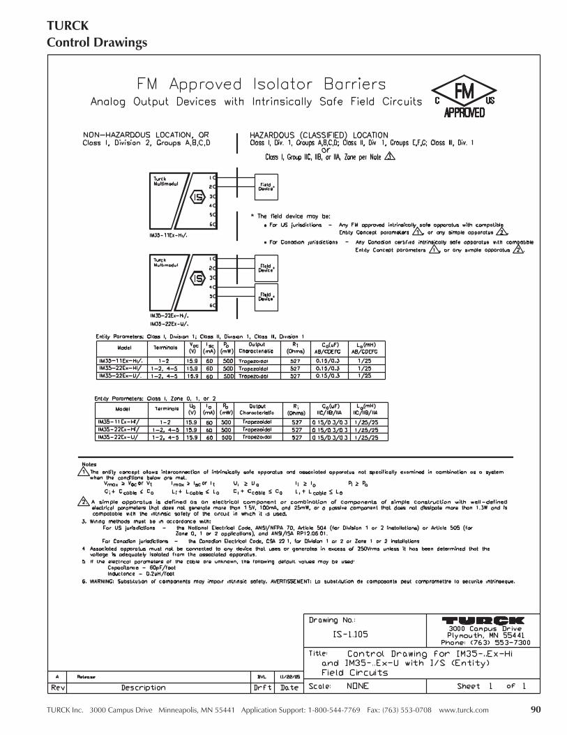
TURCK Inc. 3000 Campus Drive Minneapolis, MN 55441 Application Support: 1-800-544-7769 Fax: (763) 553-0708 www.turck.com 90
TURCKControl Drawings

91 TURCK Inc. 3000 Campus Drive Minneapolis, MN 55441 Application Support: 1-800-544-7769 Fax: (763) 553-0708 www.turck.com
TURCKControl Drawings

TURCK Inc. 3000 Campus Drive Minneapolis, MN 55441 Application Support: 1-800-544-7769 Fax: (763) 553-0708 www.turck.com 92
Our interactive e-newsletter full of exclusive insights, tips and tools to help make your manufacturingprocesses run smoothly. The TURCK Times is your source for news about TURCK products and industryupdates.
Registering is easy and only requires your e-mail address. You are not obligated for future contact orpurchase, and you may opt-in or out of the e-mail list at any time! We value your time and privacy, and willnot share your information with another party.
Sign up today at www.turck.com/elist!
Register to receive the TURCK TIMES ...

93 TURCK Inc. 3000 Campus Drive Minneapolis, MN 55441 Application Support: 1-800-544-7769 Fax: (763) 553-0708 www.turck.com
TURCKInterface Technology
TURCK Inc. sells its products through Authorized Distributors. These distributors provide ourcustomers with technical support, service and local stock. TURCK distributors are locatednationwide - including all major metropolitan marketing areas.
For Application Assistance or for the location of your nearest TURCK distributor, call:
1-800-544-7769
Specifications in this manual are subject to change without notice. TURCK also reserves the rightto make modifications and makes no guarantee of the accuracy of the information containedherein.
Literature and Media questions or concerns?Contact Marketing Communications TURCK USA - [email protected]

With TURCK intrinsically safe devices:
Use lower cost, less bulky standard enclosures.
Eliminate most cable seals and explosion-proof conduit.
Easily modify your system.
Test your system live (hot).
FM approved for Class I, II and III, Divisions 1 and 2.
•
•
•
•
Designing safety into potentially explosive areas can be a challenge. At TURCK, we’ve made the problem a whole lot easier with our line of intrinsically safe sensors and interface devices.
Rather than trying to build a fortress around the hazard, our advanced technology simply prevents ignition by limiting the thermal and electrical energy to the hazardous area. Not only is it technologically superior, it’s also easier to engineer, install and maintain – saving you time and money.
TURCK controls have proven themselves in the petro-chemical industry and meet Factory Mutual requirements for Class I, Class II and Class III, Division 1 and Division 2 environments. They easily interface to PLCs, and can provide advanced intelligence to monitor speed, temperature, pressure and other variables.
AT TURCK, WE THINKHAZARDOUS AREA
CONTROL SHOULD BE A WHOLE LOT EASIER.
www.turck.com
TURCK Inc.3000 Campus DriveMinneapolis, MN 55441Phone: 763-553-7300Fax: 763-553-0708www.turck.com
1-800-544-7769

3000 Campus DriveMinneapolis, MN 55441Phone: 1-800-553-0016
FAX: (763) 553-0706Application Support:
1-800-544-7769
Access to all TURCK catalogs, press releases, white papers and tutorials
Complete category listing of TURCK productsSearch for products
by part number, ID number or key word
www.turck.comTURCK’s USA website is your most complete and up-to-date source for product documentation, CAD fi les and more. Search results produce downloadable documentation or request for quote (RFQ). Additional product information or CAD fi les are easily requested and promptly fi lled.
Visit our site for new product releases, approvals, white papers, application support and more.
Printed in USA B4150 10/06
Option to e-mail pages
Contact a TURCK representative
Download or e-mail fi les, request for quote
Access to CAD, wiring and pinout diagrams