Embed Size (px)
Citation preview

Intrinsic Safety
Solutions
ProtectingInvestments inHazardous AreasWorldwide

1.1
Intr
oduc
tion
Intri
nsic
saf
ety
(IS)
is a
low
-ene
rgy
sign
allin
g te
chni
que
that
pr
even
ts e
xplo
sion
s fro
m o
ccur
ring
by e
nsur
ing
that
the
ene
rgy
trans
ferr
ed to
a h
azar
dous
are
a is
wel
l bel
ow th
e en
ergy
requ
ired
to in
itiat
e an
exp
losi
on.
The
ener
gy
leve
ls
mad
e av
aila
ble
for
sign
allin
g ar
e sm
all
but
usea
ble
and
mor
e th
an
adeq
uate
fo
r th
e m
ajor
ity
of
inst
rum
enta
tion
syst
ems.
The
two
mec
hani
sms
bein
g co
nsid
ered
tha
t co
uld
initi
ate
an
expl
osio
n ar
e:
• A
spa
rk
• A
hot
sur
face
1.2
The
adva
ntag
es o
f int
rinsi
c sa
fety
The
maj
or a
dvan
tage
of i
ntrin
sic
safe
ty is
that
it p
rovi
des
a so
lutio
n to
all
the
prob
lem
s of
haz
ardo
us a
reas
(fo
r eq
uipm
ent
requ
iring
lim
ited
pow
er) a
nd is
the
only
tech
niqu
e w
hich
mee
ts th
is c
riter
ion.
Th
e si
gnifi
cant
fact
ors
are
as fo
llow
s:
a) T
he IS
tech
niqu
e is
acc
epte
d th
roug
hout
the
wor
ld. T
here
is
an i
ncre
asin
g ac
cept
ance
of
inte
rnat
iona
l ce
rtific
ates
iss
ued
unde
r the
IEC
Ex s
chem
e bu
t thi
s ha
s so
me
way
to g
o. In
trins
ic
safe
ty is
an
acce
ptab
le t
echn
ique
in a
ll lo
cal l
egis
latio
n su
ch
as th
e AT
EX D
irect
ives
and
OSH
A. T
he r
elev
ant s
tand
ards
and
co
de o
f pra
ctic
e gi
ve d
etai
led
guid
ance
on
the
desi
gn a
nd u
se
of in
trins
ical
ly s
afe
equi
pmen
t to
a le
vel w
hich
is n
ot a
chie
ved
by a
ny o
f the
oth
er m
etho
ds o
f pro
tect
ion.
b) T
he s
ame
IS e
quip
men
t usu
ally
sat
isfie
s th
e re
quire
men
ts fo
r bo
th d
ust a
nd g
as h
azar
ds.
c) A
ppro
pria
te in
trins
ical
ly s
afe
appa
ratu
s ca
n be
use
d in
all
zone
s. In
par
ticul
ar, i
t is
the
only
sol
utio
n th
at h
as a
sat
isfa
ctor
y hi
stor
y of
saf
ety
for Z
one
0 in
stru
men
tatio
n. T
he u
se o
f lev
els
of
prot
ectio
n (‘i
a’, ‘
ib’ a
nd ‘i
c’) e
nsur
es th
at e
quip
men
t sui
tabl
e fo
r ea
ch le
vel o
f ris
k is
ava
ilabl
e (n
orm
ally
‘ia’
is u
sed
in Z
one
0, ‘i
b’
in Z
one
1 an
d ‘ic
’ in
Zone
2).
d) In
trins
ical
ly s
afe
appa
ratu
s an
d sy
stem
s ar
e us
ually
allo
cate
d a
grou
p IIC
gas
cla
ssifi
catio
n w
hich
ens
ures
that
the
equi
pmen
t is
co
mpa
tible
w
ith
all
gas/
air
mix
ture
s.
Occa
sion
ally
, IIB
sy
stem
s ar
e us
ed, a
s th
is p
erm
its a
hig
her
pow
er le
vel t
o be
us
ed. (
How
ever
, IIB
sys
tem
s ar
e no
t com
patib
le w
ith a
cety
lene
, hy
drog
en a
nd c
arbo
n di
sulfi
de.)
e) A
tem
pera
ture
cla
ssifi
catio
n of
T4
(135
°C)
is n
orm
ally
ac
hiev
ed, w
hich
sat
isfie
s th
e re
quire
men
t for
all
indu
stria
l gas
es
exce
pt c
arbo
n di
sulfi
de (C
S 2) w
hich
, for
tuna
tely
, is
rare
ly u
sed.
f) Fr
eque
ntly
, app
arat
us, a
nd th
e sy
stem
in w
hich
it is
use
d, c
an
be m
ade
‘ia II
C T4
’ at a
n ac
cept
able
cos
t. Th
is re
mov
es c
once
rns
Why
cho
ose
intri
nsic
saf
ety
?
abou
t ar
ea
clas
sific
atio
n,
gas
grou
ping
an
d te
mpe
ratu
re
clas
sific
atio
n in
alm
ost
all
circ
umst
ance
s an
d be
com
es t
he
univ
ersa
l saf
e so
lutio
n.
g) T
he ‘s
impl
e ap
para
tus’
con
cept
allo
ws
man
y si
mpl
e pi
eces
of
appa
ratu
s, su
ch a
s sw
itche
s, th
erm
ocou
ples
, RTD
’s a
nd ju
nctio
n bo
xes
to b
e us
ed in
intri
nsic
ally
saf
e sy
stem
s w
ithou
t the
nee
d fo
r ce
rtific
atio
n. T
his
give
s a
sign
ifica
nt a
mou
nt o
f flex
ibili
ty in
th
e ch
oice
of t
hese
anc
illar
ies.
h) T
he i
ntrin
sic
safe
ty t
echn
ique
is
the
only
tec
hniq
ue t
hat
perm
its li
ve m
aint
enan
ce w
ithin
the
haza
rdou
s ar
ea w
ithou
t the
ne
ed t
o ob
tain
‘gas
cle
aran
ce’ c
ertifi
cate
s. T
his
is p
artic
ular
ly
impo
rtant
fo
r in
stru
men
tatio
n,
sinc
e fa
ult-
findi
ng
on
de-
ener
gise
d eq
uipm
ent i
s di
fficu
lt.
i) Th
e in
stal
latio
n an
d m
aint
enan
ce re
quire
men
ts fo
r int
rinsi
cally
sa
fe a
ppar
atus
are
wel
l doc
umen
ted,
and
con
sist
ent r
egar
dles
s of
lev
el o
f pr
otec
tion.
Thi
s re
duce
s th
e am
ount
of
train
ing
requ
ired
and
decr
ease
s th
e po
ssib
ility
of d
ange
rous
mis
take
s.
j) In
trins
ic sa
fety
per
mits
the
use
of c
onve
ntio
nal in
stru
men
tatio
n ca
bles
, thu
s re
duci
ng c
osts
. Cab
le c
apac
itanc
e an
d in
duct
ance
is
ofte
n pe
rcei
ved
as a
pro
blem
but
, in
fact
, it i
s on
ly a
pro
blem
on
cab
les
long
er th
an 4
00 m
etre
s, in
sys
tem
s in
stal
led
in Z
ones
0
and
1, w
here
IIC
gas
es (
hydr
ogen
) ar
e th
e so
urce
of
risk.
Th
is is
com
para
tivel
y ra
re a
nd, i
n m
ost
circ
umst
ance
s, c
able
pa
ram
eter
s ar
e no
t a p
robl
em.
Fig
ure
1.1
- A
vaila
ble
pow
er c
urve
s
1.3
Avai
labl
e po
wer
Intri
nsic
saf
ety
is f
unda
men
tally
a l
ow e
nerg
y te
chni
que
and
cons
eque
ntly
th
e vo
ltage
, cu
rren
t an
d po
wer
av
aila
ble
is
rest
ricte
d. F
igur
e 1.
1 is
a s
impl
ified
illu
stra
tion
of t
he a
vaila
ble
pow
er in
intri
nsic
ally
saf
e ci
rcui
ts a
nd a
ttem
pts
to d
emon
stra
te
the
type
of
elec
trica
l in
stal
latio
n in
whi
ch t
he i
ntrin
sica
lly s
afe
tech
niqu
e is
app
licab
le.
The
blue
and
gre
en c
urve
s ar
e th
e ac
cept
ed d
esig
n cu
rves
use
d to
avo
id s
park
igni
tion
by re
sist
ive
limite
d ci
rcui
ts in
Gro
up II
C an
d IIB
gas
es. T
he ‘i
c’ c
urve
s ar
e le
ss s
ensi
tive
beca
use
they
do
not
requ
ire th
e ap
plic
atio
n of
a s
afet
y fa
ctor
in th
e sa
me
way
as
for
‘ia’ a
nd ‘i
b’ e
quip
men
t. In
gen
eral
the
max
imum
vol
tage
ava
ilabl
e is
set
by
cabl
e ca
paci
tanc
e (4
00 m
etre
s co
rres
pond
s to
80n
F w
hich
has
a p
erm
issi
ble
volta
ge o
f 29V
in ‘I
IC ia
’ circ
uits
) and
the
max
imum
cur
rent
by
cabl
e in
duct
ance
(400
met
res
corr
espo
nds
to 4
00μH
whi
ch h
as a
per
mis
sibl
e cu
rren
t of
300
mA
in I
IC i
a ci
rcui
ts).
A fre
quen
tly u
sed
limita
tion
on p
ower
is th
e 1.
3W, w
hich
ea
sily
per
mits
a T
4 (1
35°C
) te
mpe
ratu
re c
lass
ifica
tion.
The
se
limits
are
all
show
n in
Fig
ure
1.1.
A si
mpl
e ap
proa
ch is
to s
ay th
at if
the
appa
ratu
s ca
n be
ope
rate
d fro
m a
sou
rce
of p
ower
who
se o
utpu
t par
amet
ers
are
with
in th
e (b
lue)
hat
ched
are
a th
en it
can
rea
dily
be
mad
e in
trins
ical
ly s
afe
to ‘
IIC ia
T4’
sta
ndar
ds. I
f the
par
amet
ers
exce
ed th
ese
limits
to
a lim
ited
degr
ee th
en it
can
pro
babl
y be
mad
e in
trins
ical
ly s
afe
to
IIB o
r ‘ic
’ req
uire
men
ts.
The
first
cho
ice,
how
ever
, is
alw
ays
to c
hoos
e ‘II
C ia
T4’
equ
ipm
ent,
if it
prov
ides
ade
quat
e po
wer
and
is a
n ec
onom
ic c
hoic
e, a
s th
is
equi
pmen
t ca
n be
use
d in
all
circ
umst
ance
s (e
xcep
t if
carb
on
disu
lfide
(CS
2) is
the
haz
ardo
us g
as,
in w
hich
cas
e th
ere
are
othe
r pro
blem
s).
In p
ract
ice
alm
ost a
ll lo
w v
olta
ge in
stru
men
tatio
n ca
n be
mad
e ‘II
B ic
T4’
as
the
limits
are
set
by
the
leas
t se
nsiti
ve o
f th
e ig
nitio
n cu
rves
in F
igur
e 1.
1 (ty
pica
lly 2
4V 5
00 m
A). T
he ‘I
IB ic
’ sp
ecifi
catio
n do
es r
estri
ct a
pplic
atio
n to
Zon
e 2
and
whe
re t
he
haza
rdou
s ga
s is
not
hyd
roge
n, a
cety
lene
or c
arbo
n di
sulfi
de b
ut
is s
till a
pplic
able
to a
larg
e ra
nge
of in
stal
latio
ns.
1.4
Conc
lusi
onIn
trins
ic
safe
ty
is
the
natu
ral
choi
ce
for
all
low
vo
ltage
in
stru
men
tatio
n pr
oble
ms.
Ade
quat
e so
lutio
ns e
xist
whi
ch a
re
com
patib
le w
ith a
ll ga
ses
and
area
cla
ssifi
catio
ns. T
he te
chni
que
prev
ents
exp
losi
ons
rath
er t
han
reta
ins
them
whi
ch m
ust
be
pref
erab
le, a
nd th
e ‘li
ve m
aint
enan
ce’ f
acili
ty e
nabl
es c
onve
ntio
nal
inst
rum
ent p
ract
ice
to b
e us
ed.
1.
23
“App
ropr
iate
intr
insi
cally
saf
e ap
para
tus
can
be u
sed
in a
ll zo
nes”
MTL4500 In
stal
latio
n.

Tabl
e 2.
1 sh
ows a
repr
esen
tativ
e ga
s for
eac
h gr
oup
and
the
min
imum
en
ergy
requ
ired
to ig
nite
it. II
C is
clear
ly th
e m
ost s
ensit
ive. A
ppar
atus
ca
n be
des
igne
d to
be
acce
ptab
ly s
afe
in a
ny o
f th
ese
grou
ps.
Usua
lly a
ppar
atus
is d
esig
ned
to b
e sa
fe in
IIC,
bec
ause
it c
an th
en
be u
sed
in a
ny g
as a
tmos
pher
e. S
omet
imes
a II
B cl
assi
ficat
ion
is
used
as
this
per
mits
slig
htly
hig
her
pow
ers
to b
e av
aila
ble.
Onl
y ve
ry ra
rely
how
ever
is a
ppar
atus
des
igne
d fo
r the
IIA
clas
sific
atio
n be
caus
e th
is re
stric
ts it
s us
e to
this
gro
up a
lone
.Ap
para
tus i
s usu
ally
ass
esse
d us
ing
the
curv
es a
nd ta
bles
incl
uded
in
the
appa
ratu
s st
anda
rd w
hich
list
s ac
cept
able
leve
ls o
f cur
rent
an
d vo
ltage
. Mor
e co
mpl
ex c
ircui
ts a
re c
heck
ed w
ith ‘s
park
test
’ ap
para
tus;
nor
mal
ly th
e pr
eser
ve o
f cer
tifyi
ng a
utho
ritie
s.
2.8
Tem
pera
ture
cla
ssifi
catio
nTh
e se
cond
met
hod
of c
ausi
ng a
n ex
plos
ion
is n
orm
ally
con
side
red
to b
e ig
nitio
n by
a h
ot s
urfa
ce. W
hen
a ga
s is
hea
ted
abov
e its
ig
nitio
n te
mpe
ratu
re i
t m
ay s
pont
aneo
usly
ign
ite.
The
igni
tion
tem
pera
ture
var
ies
with
the
gas
and
is n
ot c
orre
late
d to
igni
tion
ener
gy. C
onse
quen
tly, w
hen
sele
ctin
g ap
para
tus,
bot
h pr
oper
ties
of th
e ex
plos
ive
gas
have
to b
e co
nsid
ered
.Ap
para
tus
is c
lass
ified
into
tem
pera
ture
(‘T’
) cla
sses
dep
endi
ng o
n its
max
imum
per
mitt
ed s
urfa
ce te
mpe
ratu
re.
Tab
le 2
.2 T
he ‘T’
cla
sses
The
stan
dard
ena
bles
alm
ost a
ll ap
para
tus,
diss
ipat
ing
not m
ore
than
1.
3W, to
be a
lloca
ted
a tem
pera
ture
clas
sifica
tion
of T4
(135
°C). A
lmos
t al
l int
rinsic
ally
safe
fiel
d m
ount
ed a
ppar
atus
mee
ts th
e re
quire
men
ts
of T
4 te
mpe
ratu
re c
lass
ifica
tion,
whi
ch p
erm
its it
s us
e in
all
indu
stria
l ga
s at
mos
pher
es e
xcep
t in
thos
e co
mpr
ising
car
bon
disu
lfide
(CS 2)
and
air.
Thes
e re
quire
a T
6 cla
ssifi
catio
n, w
hich
is d
ifficu
lt to
ach
ieve
at
hig
h am
bien
t te
mpe
ratu
res.
Ther
e ar
e al
so t
oxic
ity p
robl
ems
asso
ciat
ed w
ith c
arbo
n di
sulfi
de.
The
othe
r tem
pera
ture
that
nee
ds to
be
cons
ider
ed fo
r eac
h pi
ece
of
appa
ratu
s is i
ts a
mbi
ent t
empe
ratu
re ra
ting,
whi
ch d
oes d
irect
ly af
fect
th
e sa
fety
of t
he a
ppar
atus
in s
ever
al w
ays.
Appa
ratu
s no
rmal
ly m
ount
ed i
n th
e sa
fe a
rea
but
whi
ch a
ffect
s th
e sa
fety
of
the
intri
nsic
ally
safe
sys
tem
(su
ch a
s th
e in
trins
ical
ly
safe
inte
rface
in F
igur
e 2.
1) is
cal
led
‘ass
ocia
ted
appa
ratu
s’. S
uch
appa
ratu
s do
es n
ot n
eed
to b
e te
mpe
ratu
re c
lass
ified
but
mus
t be
used
with
in it
s sp
ecifi
ed a
mbi
ent t
empe
ratu
re ra
nge.
2.1
Defin
ition
of I
ntrin
sic
Safe
tyTh
e de
finiti
on
of
intri
nsic
sa
fety
us
ed
in
the
rele
vant
IE
C ap
para
tus
stan
dard
IEC
6007
9-11
is a
‘typ
e of
pro
tect
ion
base
d on
the
res
trict
ion
of e
lect
rical
ene
rgy
with
in a
ppar
atus
and
of
inte
rcon
nect
ing
wiri
ng
expo
sed
to
the
pote
ntia
lly
expl
osiv
e at
mos
pher
e to
a l
evel
bel
ow t
hat
whi
ch c
an c
ause
ign
ition
by
eith
er s
park
ing
or h
eatin
g ef
fect
s’. T
his
is a
con
cise
sta
tem
ent o
f in
tent
to in
trodu
ce a
mul
ti-fa
cete
d su
bjec
t.
2.2
Typi
cal i
ntrin
sica
lly s
afe
syst
emFi
gure
2.1
illu
stra
tes
a ty
pica
l int
rinsi
cally
saf
e (IS
) sys
tem
whe
re
the
safe
per
form
ance
of
each
pie
ce o
f ap
para
tus
is d
epen
dent
on
the
inte
grity
of a
ll th
e eq
uipm
ent i
n th
e sy
stem
. For
exa
mpl
e,
the
safe
ty o
f the
Tem
pera
ture
Tra
nsm
itter
(Tx)
dep
ends
upo
n th
e am
ount
of e
nerg
y su
pplie
d by
the
IS In
terfa
ce.
In m
ost p
roce
ss c
ontro
l app
licat
ions
, eac
h pi
ece
of a
ppar
atus
ina
syst
em is
indi
vidu
ally
certi
fied.
A d
ocum
ent t
hat c
onfir
ms t
he sa
fety
of
the
who
le s
yste
m is
then
pro
duce
d us
ing
the
info
rmat
ion
from
th
e in
divi
dual
app
arat
us c
ertifi
cate
s, in
acc
orda
nce
with
the
syst
em
stan
dard
IEC
6007
9-25
. Thi
s sy
stem
doc
umen
t als
o in
clud
es d
etai
ls
of c
able
type
s an
d si
mpl
e ap
para
tus
used
in th
e sy
stem
.It
is i
mpo
rtant
to
reco
gnis
e th
at w
here
pie
ces
of i
ntrin
sica
lly
safe
app
arat
us a
re in
terc
onne
cted
, it i
s th
e sa
fety
of t
he s
yste
m
that
mus
t be
est
ablis
hed.
The
re a
re h
owev
er s
ome
exam
ples
of
appa
ratu
s w
hich
sta
nd a
lone
, suc
h as
mob
ile ra
dios
and
por
tabl
e ga
s de
tect
ors,
whe
re th
e sy
stem
app
roac
h is
not
rele
vant
.
2.3
Leve
ls o
f pro
tect
ion
Intri
nsic
saf
ety
utili
ses
thre
e le
vels
of
prot
ectio
n, ‘
ia’,
‘ib’
and
‘ic’
whi
ch a
ttem
pt t
o ba
lanc
e th
e pr
obab
ility
of
an e
xplo
sive
at
mos
pher
e be
ing
pres
ent
agai
nst
the
prob
abili
ty o
f an
ign
ition
ca
pabl
e si
tuat
ion
occu
rrin
g.
An In
trodu
ctio
n to
Intri
nsic
Saf
ety
‘ia
’
This
offe
rs th
e hig
hest
leve
l of p
rote
ctio
n an
d is
gen
eral
ly co
nsid
ered
as
bei
ng a
dequ
atel
y sa
fe fo
r use
in th
e m
ost h
azar
dous
loca
tions
(Z
one
0) b
ecau
se th
e po
ssib
ility
of t
wo
‘faul
ts’ (
see
oppo
site
) and
a
fact
or o
f saf
ety
of 1
.5 is
con
side
red
in th
e as
sess
men
t of s
afet
y.
‘ib
’
‘ib’
appa
ratu
s, w
hich
is
adeq
uate
ly s
afe
with
one
fau
lt an
d a
fact
or o
f saf
ety
of 1
.5 is
con
side
red
safe
for u
se in
less
freq
uent
ly
haza
rdou
s ar
eas
(Zon
e 1)
.
‘ic’
‘ic’ a
ppar
atus
whi
ch is
ass
esse
d in
‘nor
mal
ope
ratio
n’ w
ith a
uni
ty
fact
or o
f saf
ety
is g
ener
ally
acc
epta
ble
in in
frequ
ently
haz
ardo
us
area
s (Z
one
2). T
he ‘i
c’ c
once
pt is
rel
ativ
ely
new
(200
5) a
nd w
ill
repl
ace
the
‘ene
rgy-
limite
d’ (
nL)
of t
he t
ype
‘n’
stan
dard
IEC
60
079-
15 a
nd p
ossi
bly
the
‘non
-ince
ndiv
e’ c
once
pt o
f No
rth
Amer
ican
sta
ndar
ds.
It is
usu
al fo
r a
syst
em to
be
allo
cate
d a
leve
l of p
rote
ctio
n as
a
who
le, d
epen
ding
on
the
leve
l of
prot
ectio
n of
the
app
arat
us in
th
e sy
stem
. How
ever
it is
pos
sibl
e fo
r di
ffere
nt p
arts
of a
sys
tem
to
hav
e di
ffere
nt le
vels
of
prot
ectio
n w
here
sui
tabl
e se
greg
atio
n ex
ists
. Thi
s m
ust b
e m
ade
clea
r in
the
syst
em d
ocum
enta
tion.
Fig
ure
2.1
- T
ypic
al IS
sys
tem
2.
2.4
Faul
tsIf
a fa
ult
can
adve
rsel
y af
fect
the
saf
ety
of t
he e
quip
men
t it
is
calle
d a
‘cou
ntab
le’
faul
t. Th
e si
tuat
ion
is f
urth
er c
ompl
icat
ed
beca
use
the
appa
ratu
s st
anda
rd p
erm
its s
ome
spec
ially
des
igne
d co
mpo
nent
s to
be
rega
rded
as
infa
llibl
e an
d so
me
inad
equa
tely
de
sign
ed fe
atur
es to
be
faile
d in
nor
mal
ope
ratio
n. C
onse
quen
tly
ther
e ar
e fa
ults
that
are
not
con
side
red
to h
appe
n, fa
ults
, whi
ch
are
coun
ted,
and
faul
ts, w
hich
are
impo
sed
but n
ot c
ount
ed.
One
of t
he m
ajor
adv
anta
ges
of i
ntrin
sic
safe
ty i
s th
at ‘
live
mai
nten
ance
’ on
equi
pmen
t is
perm
itted
with
out t
he n
eces
sity
of
obta
inin
g ‘g
as c
lear
ance
’ cer
tifica
tes.
A c
onse
quen
ce o
f thi
s is
that
du
ring
the
safe
ty a
naly
sis
the
poss
ibili
ty o
f op
en c
ircui
ting
and
shor
t-ci
rcui
ting
any
field
wiri
ng is
rega
rded
as
norm
al o
pera
tion.
Fortu
nate
ly u
nder
stan
ding
the
app
arat
us s
tand
ard
and
faul
ts i
s on
ly n
eces
sary
for a
ppar
atus
des
igne
rs a
nd c
ertif
ying
aut
horit
ies.
Th
e ap
para
tus
certi
ficat
es re
mov
e th
e ne
cess
ity to
con
side
r fau
lts,
exce
pt fo
r fiel
d w
iring
faul
ts, i
n sy
stem
des
ign.
2.5
Sim
ple
appa
ratu
sIn
gen
eral
, int
rinsi
cally
saf
e ap
para
tus
is c
ertifi
ed; u
sual
ly b
y an
in
depe
nden
t bod
y su
ch a
s an
Acc
redi
ted
Certi
ficat
ion
Body
(ACB
) un
der t
he IE
C Ex
sch
eme.
Sel
f-ce
rtific
atio
n by
the
man
ufac
ture
r of
‘ic’ e
quip
men
t is
also
qui
te c
omm
only
acc
epte
d.Th
e ex
cept
ion
to th
e ru
le is
‘sim
ple
appa
ratu
s’, w
hich
is c
onsi
dere
d no
t to
app
reci
ably
affe
ct t
he i
ntrin
sic
safe
ty o
f th
e sy
stem
. Th
is
appa
ratu
s is
exe
mpt
ed f
rom
the
req
uire
men
t fo
r ce
rtific
atio
n. T
he
sim
ple
requ
irem
ents
are
cle
arly
spe
cifie
d in
the
appa
ratu
s st
anda
rd.
‘Sim
ple
appa
ratu
s’ s
houl
d al
way
s be
rea
dily
dem
onst
rabl
e to
be
adeq
uate
ly s
afe.
The
usu
al e
xam
ples
are
sw
itche
s, th
erm
ocou
ples
, RT
D’s
and
junc
tion
boxe
s.
2.6
Cabl
esBe
caus
e ca
bles
hav
e in
duct
ance
and
cap
acita
nce,
and
hen
ce
ener
gy s
tora
ge c
apab
ilitie
s, th
ey c
an a
ffect
sys
tem
saf
ety.
Cons
eque
ntly
the
sys
tem
des
ign
impo
ses
rest
rictio
ns o
n th
e am
ount
of e
ach
of th
ese
para
met
ers.
A g
reat
dea
l has
bee
n w
ritte
n on
this
sub
ject
but
onl
y ra
rely
is th
ere
a se
rious
lim
itatio
n pl
aced
on
the
avai
labl
e ca
ble.
As c
able
faul
ts a
re ta
ken
into
acc
ount
dur
ing
the
syst
em a
naly
sis,
th
e ty
pe o
f cab
le in
indi
vidu
al in
stal
latio
ns is
not
clo
sely
spe
cifie
d in
the
syst
em s
tand
ard.
The
cho
ice
is th
eref
ore
dete
rmin
ed b
y th
e ne
ed fo
r rel
iabl
e sy
stem
ope
ratio
n.W
here
int
rinsi
cally
saf
e sy
stem
s ar
e co
mbi
ned
in a
mul
ti-co
re,
then
the
re a
re s
peci
al r
equi
rem
ents
. Th
ese
dete
rmin
e w
hich
ad
ditio
nal f
aults
hav
e to
be
cons
ider
ed.
2.7
Gas
clas
sific
atio
nTh
e am
ount
of e
nerg
y re
quire
d to
igni
te a
par
ticul
ar g
as/a
ir m
ixtu
re
varie
s fo
r ea
ch g
as. I
ndus
trial
gas
es c
apab
le o
f bei
ng ig
nite
d ar
e di
vide
d, in
the
UK, i
nto
thre
e cl
asse
s, II
A, II
B an
d IIC
.
Typ
ica
l G
as
G
as
Gro
up
Ig
nit
ion
en
erg
y
Met
hane
IIA
16
0μJ
Ethy
lene
IIB
80
μJHy
drog
en
IIC
20μJ
Tab
le 2
.1: Ty
pic
al g
ase
s, t
heir
cla
ssifi
cati
on
& ig
nit
ion
en
erg
ies
T1
T2
T3
T4
T5
T6
450°
C
300°
C
200°
C
135°
C
100°
C
80°C
45

2.9
Cate
gorie
s an
d eq
uipm
ent s
afet
y le
vels
Whe
n th
e Eu
rope
an D
irect
ive
(ATE
X) f
or a
ppar
atus
for
use
in
haza
rdou
s ar
eas
(94/
9/EC
) was
cre
ated
, it i
ntro
duce
d th
e co
ncep
t of
cat
egor
ies,
whi
ch w
as in
tend
ed to
cla
rify
the
Zone
(s) i
n w
hich
ap
para
tus c
ould
safe
ly b
e us
ed. U
nfor
tuna
tely
, and
for n
othi
ng m
ore
than
ped
antic
reas
ons,
it w
as d
ecid
ed th
at a
cat
egor
y 0
wou
ld n
ot
be u
sed
and
the
resu
lt w
as t
he c
onfu
sing
situ
atio
n ill
ustra
ted
in
Tabl
e 2.
3, w
here
the
cate
gory
and
Zon
e nu
mbe
rs d
iffer
.M
ore
rece
ntly
(200
4) th
e IE
C to
ok u
p th
e co
ncep
t of i
dent
ifyin
g th
e le
vel o
f pro
tect
ion
offe
red
by a
pie
ce o
f app
arat
us a
nd a
lso
paid
a
little
mor
e at
tent
ion
to ri
sk a
naly
sis
as a
met
hod
of d
eter
min
ing
the
acce
ptab
le u
se o
f equ
ipm
ent.
The
resu
lt w
as th
e cr
eatio
n of
eq
uipm
ent
prot
ectio
n le
vels
(EP
Ls),
whi
ch a
re s
imila
r to
ATE
X ca
tego
ries
but
have
num
bers
tha
t al
ign
with
the
ir no
rmal
Zon
es
of u
se.
In p
ract
ice
both
cat
egor
ies
and
EPLs
alig
n w
ith t
he l
evel
s of
pr
otec
tion
‘ia’,
‘ib’
and
‘ic’
as in
dica
ted
in T
able
2.3
and
, as
far
as in
trins
ic s
afet
y is
con
cern
ed, t
hey
can
larg
ely
be ig
nore
d, a
s th
e le
vel o
f pr
otec
tion
is a
lread
y de
fined
as
‘ia’,
‘ib’ o
r ‘ic
’. Th
ey
do h
owev
er a
ppea
r on
app
arat
us m
arki
ng a
nd c
ertifi
cate
s an
d co
nseq
uent
ly n
eed
to b
e ex
plai
ned.
2.10
Sum
mar
yIn
trins
ic s
afet
y of
fers
an
acce
ptab
le le
vel o
f saf
ety
in a
ll ha
zard
ous
loca
tions
. Arg
uabl
y it
is s
afer
and
less
pro
ne to
acc
iden
tal e
rror
s th
an o
ther
met
hods
of p
rote
ctio
n. T
his
com
bine
d w
ith it
s fle
xibl
e us
e of
ava
ilabl
e ap
para
tus
and
the
abili
ty t
o do
‘liv
e w
orki
ng’
mea
ns t
hat
it is
the
nat
ural
cho
ice
for
inst
rum
enta
tion
syst
ems
in h
azar
dous
are
as. F
or e
xam
ple
it is
the
only
tech
niqu
e w
hich
is
read
ily a
pplic
able
to Z
one
0 lo
catio
ns.
The
intro
duct
ion
of t
he ‘
ic’
conc
ept
com
plet
es t
he p
ictu
re. T
he
esse
ntia
l req
uire
men
ts o
f an
intri
nsic
ally
saf
e sy
stem
are
:
• T
he s
yste
m m
ust w
ork.
• T
he a
ppar
atus
in th
e sy
stem
mus
t be
‘cer
tified
’ or ‘
sim
ple’
.•
The
com
patib
ility
of t
he a
ppar
atus
mus
t be
esta
blis
hed.
• T
he le
vel o
f pro
tect
ion
of th
e sy
stem
est
ablis
hed.
• T
he te
mpe
ratu
re c
lass
ifica
tion
and
ambi
ent t
empe
ratu
re
ratin
g of
eac
h pi
ece
of a
ppar
atus
est
ablis
hed.
• T
he re
quire
men
ts o
f the
cab
le e
stab
lishe
d.
Leve
l of
Pro
tecti
on
C
ou
nta
ble
Fa
ult
s
ATE
X C
ate
gory
IE
C E
PL
Norm
al Z
on
e o
f U
se
ia
2 1
0
0
ib
1
2
1
1ic
0
3
2
2
Tab
le 2
.3 R
elat
ions
hips
bet
wee
n di
ffere
nt m
etho
ds o
f ass
essi
ng s
afet
y le
vels
3.1
Gene
ral
The
long
ter
m c
ontin
ued
safe
ty o
f an
int
rinsi
cally
saf
e sy
stem
de
pend
s on
ade
quat
e in
spec
tion
and
mai
nten
ance
. The
rel
evan
t IE
C st
anda
rd i
s IE
C 60
079-
17,
whi
ch d
eals
com
preh
ensi
vely
w
ith a
ll m
etho
ds o
f pr
otec
tion.
Whe
re i
nsta
llatio
ns a
re r
equi
red
to c
ompl
y w
ith t
he E
urop
ean
‘use
r’ Di
rect
ive
1999
/92/
EC a
do
cum
ente
d in
spec
tion
proc
edur
e be
com
es a
par
t of t
he re
quire
d ris
k an
alys
is.
Any
wor
k on
a h
azar
dous
pla
nt n
eeds
to ta
ke in
to a
ccou
nt o
vera
ll pl
ant s
afet
y. C
onse
quen
tly it
is n
eces
sary
to c
ompl
y w
ith th
e sa
fety
pr
actic
es o
f th
e pa
rticu
lar
inst
alla
tion
(for
exam
ple
wor
k pe
rmits
), ev
en th
ough
the
risk
of ig
nitio
n fro
m th
e in
trins
ical
ly s
afe
circ
uits
is
min
imal
, and
gas
cle
aran
ce c
ertifi
cate
s ar
e no
t nec
essa
ry. I
n so
me
way
s th
is is
eve
n m
ore
impo
rtant
in th
e pr
e-co
mm
issi
onin
g st
age.
If th
ere
are
sign
ifica
nt c
hang
es in
the
pla
nt o
pera
tion,
whi
ch f
or
exam
ple
mod
ify t
he a
rea
clas
sific
atio
n th
en t
he s
afet
y an
alys
is
mus
t be
revi
ewed
, the
doc
umen
tatio
n m
odifi
ed, a
nd p
ossi
bly
the
insp
ectio
n pr
oced
ure
chan
ged
and/
or re
peat
ed.
The
proc
edur
e pl
aces
the
onus
for e
nsur
ing
that
the
equi
pmen
t use
d is
sui
tabl
e fo
r its
loca
tion
on th
e cr
eato
r of t
he in
stal
latio
n dr
awin
g.Th
e na
ture
of a
n in
spec
tion
depe
nds
on h
ow w
ell t
he in
stal
latio
n dr
awin
g, w
hich
cha
nges
the
syst
em d
esig
n dr
awin
g in
to a
dra
win
g sp
ecifi
c to
a p
artic
ular
inst
alla
tion,
has
bee
n ca
rrie
d ou
t.If
the
docu
men
tatio
n is
inad
equa
te th
en a
ny in
spec
tion
can
only
be
carr
ied
out b
y so
meo
ne w
ith d
etai
led
know
ledg
e of
the
plan
t and
ex
cept
iona
l exp
ertis
e in
haz
ardo
us a
rea
prac
tice.
Bec
ause
suc
h a
pers
on ra
rely
exi
sts,
this
ana
lysi
s as
sum
es th
at th
e do
cum
enta
tion
is a
dequ
ate,
and
use
s Fi
gure
3.1
to il
lust
rate
the
proc
ess.
If th
e pe
rson
doi
ng a
n in
spec
tion
does
not
und
erst
and
som
e as
pect
of
the
draw
ing,
or b
elie
ves
it co
uld
be w
rong
, the
n th
ey s
houl
d be
en
cour
aged
to q
uest
ion
the
docu
men
t. IE
C 60
079-
17 re
quire
s th
e
Inst
alla
tion
& In
spec
tion
of IS
app
arat
us
- A
n in
trodu
ctio
n
iden
tifica
tion
of ‘a
tech
nica
l per
son
with
exe
cutiv
e fu
nctio
n’ to
be
resp
onsi
ble
for i
nspe
ctio
n re
late
d m
atte
rs in
eac
h in
stal
latio
n. T
his
pers
on s
houl
d be
kno
wn
to t
he t
echn
icia
n do
ing
the
insp
ectio
n,
and
shou
ld b
e av
aila
ble
and
able
to a
nsw
er q
uest
ions
.Th
e in
stal
latio
n dr
awin
g sh
ould
tak
e in
to a
ccou
nt w
hat
can
be
chec
ked
on t
he i
nsta
llatio
n. F
or e
xam
ple,
quo
ting
perm
issi
ble
capa
cita
nce
and
indu
ctan
ce f
or a
cab
le i
s no
t us
eful
, be
caus
e al
thou
gh it
is p
ossi
ble
to c
heck
thes
e pa
ram
eter
s, it
is n
ot e
asy
to d
o so
. Sta
ting
an a
ccep
tabl
e ty
pe a
nd le
ngth
is m
uch
mor
e us
eful
.Th
e us
e of
info
rmat
ion
avai
labl
e fro
m ‘i
ntel
ligen
t’ in
stru
men
ts c
an
cons
ider
ably
red
uce
the
rout
ine
insp
ectio
n co
nsid
ered
nec
essa
ry
on a
n in
trins
ical
ly s
afe
syst
em.
The
use
of t
his
inte
llige
nce
to
redu
ce th
e in
spec
tion
requ
irem
ent i
s re
cogn
ised
in IE
C600
79-1
7 cl
ause
5.3
.1 b
ut n
ot d
iscu
ssed
in d
etai
l.Th
e ab
ility
to i
dent
ify a
spe
cific
fiel
d in
stru
men
t fro
m t
he s
afe
area
, with
out
havi
ng t
o go
and
rea
d th
e la
bel o
n th
e in
stru
men
t, is
a s
igni
fican
t ad
vant
age.
Alm
ost
all
of t
he d
igita
l, “i
ntel
ligen
t”
inst
rum
ents
(HAR
T, Fo
unda
tion
Fiel
dbus
, etc
) ena
ble
the
seria
l num
ber
of a
n in
stru
men
t to
be re
ad re
mot
ely.
The
com
pute
r rec
ord
can
then
be
use
d to
con
firm
that
it is
the
spec
ified
inst
rum
ent,
thus
ens
urin
g it
satis
fies
all t
he re
quire
men
ts o
f the
par
ticul
ar in
stal
latio
n.Th
is t
ype
of c
heck
can
be
done
at
frequ
ent
inte
rval
s w
ithou
t in
terfe
ring
with
ope
ratio
nal
requ
irem
ents
. Th
e in
spec
tion
of a
n in
stru
men
t is
then
red
uced
to lo
okin
g fo
r m
echa
nica
l dam
age
or
exce
ssiv
e co
rros
ion
whi
ch is
com
para
tivel
y ea
sy a
nd s
igni
fican
tly
less
tedi
ous.
Fig
ure
3.1
- T
ypic
al in
stal
latio
n dr
awin
g fo
r IS
syst
em
3.
MTL4500/5
500 b
ackp
lane
and
DIN
-rai
l mou
nted
saf
ety
isol
ator
s.
67

3.1
Gene
ral -
con
tinue
d A
rem
ote
chec
k th
at th
e in
stru
men
t is
func
tioni
ng c
orre
ctly
doe
s no
t nec
essa
rily
ensu
re th
at it
is s
till s
afe
but i
t doe
s co
nfirm
that
it
has
not b
een
sign
ifica
ntly
dam
aged
and
is p
roba
bly
still
saf
e.Th
is d
oes
impl
y th
at a
ny m
alfu
nctio
n sh
ould
be
quic
kly
corr
ecte
d or
the
def
ectiv
e eq
uipm
ent
rem
oved
or
at l
east
mad
e sa
fe.
A fre
quen
t ch
eck
on f
unct
iona
lity
is a
sig
nific
ant
fact
or i
n fu
rther
re
duci
ng th
e ris
k as
soci
ated
with
any
haz
ardo
us a
rea
appa
ratu
s.Ho
w fa
r thi
s typ
e of
aut
omat
ic in
spec
tion
can
sim
plify
the
insp
ectio
n pr
oced
ure
is a
dec
isio
n fo
r the
end
-use
r. Bu
t it i
s ar
guab
ly a
mor
e re
liabl
e te
chni
que
than
man
ual
insp
ectio
n an
d si
mpl
ifies
the
re
cord
ing
of t
he p
roce
ss.
A re
lativ
ely
sim
ple
com
pute
r sy
stem
ca
n gi
ve r
eady
acc
ess
to t
he r
elev
ant
inst
alla
tion
and
syst
em
draw
ings
, whi
ch m
ay b
e re
quire
d if
furth
er in
vest
igat
ion
is th
ough
t to
be
nece
ssar
y.So
me
user
s m
ay c
onsi
der
it de
sira
ble
to d
o an
occ
asio
nal
thor
ough
spo
t che
ck a
s re
assu
ranc
e th
at th
e sy
stem
is fu
nctio
ning
bu
t th
is is
a c
ouns
el o
f pe
rfect
ion.
The
se t
echn
ique
s, c
ombi
ned
with
the
avai
labi
lity
of c
ertifi
cate
s an
d m
anua
ls o
n m
anuf
actu
rers
’ w
eb s
ites,
can
lead
to
safe
r in
stal
latio
ns a
nd a
red
uctio
n in
the
bu
reau
crat
ic lo
ad c
reat
ed b
y sa
fety
legi
slat
ion.
3.2
Initi
al in
spec
tion
An in
itial
insp
ectio
n to
ens
ure
that
the
inst
alla
tion
com
plie
s w
ith
the
inst
alla
tion
draw
ing
is c
ritic
al. W
here
an
adeq
uate
dra
win
g su
ch a
s Fi
gure
3.1
exi
sts,
the
initi
al in
spec
tion
shou
ld e
nsur
e th
at
the
actu
al in
stal
latio
n co
nfor
ms
to th
e dr
awin
g.Us
ually
this
invo
lves
che
ckin
g ea
ch in
divi
dual
loop
sta
ge b
y st
age,
w
hich
invo
lves
a g
ood
deal
of o
peni
ng e
nclo
sure
s an
d cl
ambe
ring
over
stru
ctur
es. W
here
the
tech
nici
an in
volv
ed is
sui
tabl
y qu
alifi
ed
this
ins
pect
ion
can
be c
ombi
ned
with
the
ope
ratio
nal
chec
ks.
How
ever
som
e or
gani
satio
ns s
epar
ate
the
two
requ
irem
ents
, pr
efer
ring
‘inde
pend
ent’
safe
ty in
spec
tions
.Th
is s
epar
atio
n of
fun
ctio
ns is
not
con
duci
ve t
o sh
orte
ning
sta
rt up
tim
es.
Freq
uent
ly
the
initi
al
insp
ectio
n de
mon
stra
tes
the
inad
equa
cy o
f pla
nt la
belli
ng, a
nd th
e op
portu
nity
to im
prov
e th
is
feat
ure
shou
ld n
ot b
e m
isse
d.
3.3
Perio
dic
insp
ectio
nsTh
e ob
ject
ive
of p
erio
dic
insp
ectio
ns is
to e
nsur
e th
e sy
stem
has
no
t ap
prec
iabl
y de
terio
rate
d an
d ha
s no
t be
en m
odifi
ed i
n an
un
auth
oris
ed w
ay. T
he re
quire
d fre
quen
cy o
f per
iodi
c in
spec
tions
is
influ
ence
d by
man
y fa
ctor
s, s
uch
as th
e im
med
iate
env
ironm
ent,
the
pres
ence
of
corr
osiv
e at
mos
pher
es a
nd t
he s
usce
ptib
ility
to
mec
hani
cal d
amag
e. A
usu
al s
tarti
ng p
oint
is to
con
side
r a th
ree-
year
cyc
le, i
nspe
ctin
g a
third
of
the
appa
ratu
s ev
ery
year
. If
the
insp
ectio
n sh
ows
wid
espr
ead
dete
riora
tion
then
the
ins
pect
ion
perio
d sh
ould
be
shor
tene
d an
d re
med
ial a
ctio
n ta
ken.
Esta
blis
hing
that
the
inte
nded
app
arat
us is
stil
l in
plac
e is
rela
tivel
y ea
sy p
rovi
ding
that
the
appa
ratu
s ha
s a
uniq
ue id
entit
y.Us
ually
the
man
ufac
ture
rs t
ype
num
ber
is a
dequ
ate.
Muc
h ha
s be
en w
ritte
n ab
out c
heck
ing
the
mar
king
on
the
labe
ls b
ut e
xcep
t, as
an
inte
llect
ual e
xerc
ise
ther
e is
littl
e po
int.
Prov
idin
g th
at t
he
insp
ecto
r is c
onvi
nced
that
the
appa
ratu
s is t
he in
tend
ed a
ppar
atus
th
en h
e ha
s fu
lfille
d hi
s fu
nctio
n. H
e sh
ould
be
enco
urag
ed
to a
sk q
uest
ions
if h
e is
unh
appy
abo
ut t
he a
ppar
atus
or
if th
e ci
rcum
stan
ces
of u
se h
ave
chan
ged
but
fund
amen
tally
it is
not
re
ason
able
to e
xpec
t a d
etai
led
anal
ysis
of e
very
loop
.It
is u
sual
ly w
orth
cre
atin
g se
para
te d
raw
ings
of
such
thi
ngs
as
inte
rface
cab
inet
s an
d ju
nctio
n bo
xes
so t
hat
they
can
be
read
ily
chec
ked
for a
ny si
gn o
f una
utho
rised
mod
ifica
tion.
Sim
ilarly
pre
parin
g sh
ort l
ists
of fi
eld
equi
pmen
t gro
uped
in a
par
ticul
ar a
rea
with
thei
r
esse
ntia
l poi
nts
of in
spec
tion
can
shor
ten
the
time
requ
ired.
Mos
t mod
ern
(sm
art)
inst
rum
ents
can
be
iden
tified
from
the
safe
ar
ea c
ompu
ter.
It is
rela
tivel
y si
mpl
e fo
r the
com
pute
r to
chec
k th
at
the
field
inst
rum
ent i
s un
chan
ged
and
rais
e a
flag
if it
is c
hang
ed.
This
can
be
done
fre
quen
tly.
The
perio
dic
insp
ectio
n fo
r th
at
appa
ratu
s is
then
redu
ced
to c
heck
ing
for d
eter
iora
tion.
Ther
e is
a s
trong
link
bet
wee
n th
e ne
ed fo
r pe
riodi
c in
spec
tions
fo
r op
erat
iona
l and
saf
ety
reas
ons
and
it is
usu
al to
com
bine
the
requ
irem
ents
. For
exa
mpl
e, th
e sh
ort p
iece
of fi
eld
wiri
ng u
sed
for
the
final
con
nect
ion
to th
e in
stru
men
t is
ofte
n pr
one
to m
echa
nica
l da
mag
e an
d co
nseq
uent
ly i
s us
ually
inc
lude
d in
the
ins
pect
ion
proc
edur
e ev
en th
ough
its
open
or
shor
t-ci
rcui
t fai
lure
wou
ld n
ot
crea
te a
n in
cend
ive
spar
k.Th
e ch
eck
for
mec
hani
cal d
eter
iora
tion
is u
sual
ly a
qui
ck c
heck
fo
r co
rros
ion,
im
pact
dam
age,
effi
cien
cy o
f se
als,
sec
urity
of
mou
ntin
g an
d ad
equa
cy o
f ca
ble
glan
ds.
Som
e ju
dgem
ent
on
the
need
for
rep
air
or r
epla
cem
ent
is r
equi
red,
and
the
nee
d fo
r op
erat
iona
l re
liabi
lity
usua
lly d
eter
min
es t
he n
eces
sary
act
ion.
Ther
e is
how
ever
no
subs
titut
e fo
r a
wel
l-tra
ined
tech
nici
an w
ith
the
right
atti
tude
.
3.4
Test
ing
of a
ppar
atus
Som
etim
es i
t is
sug
gest
ed t
hat
appa
ratu
s sh
ould
be
rem
oved
fo
r pe
riodi
c te
stin
g. I
n pr
actic
e, i
f an
int
rinsi
cally
saf
e lo
op i
s fu
nctio
nal t
hen
it is
ver
y un
likel
y to
hav
e fa
iled
in a
dan
gero
us
mod
e. C
ompo
nent
s cr
itica
l to
safe
ty a
re d
erat
ed, s
o th
e pr
obab
ility
of
ext
erna
l circ
umst
ance
s ca
usin
g th
em to
fail
with
out c
ausi
ng a
m
alfu
nctio
n is
sm
all.
Ther
e is
a b
igge
r ris
k th
at a
mis
take
cou
ld b
e m
ade
durin
g th
e re
mov
al a
nd r
epla
cem
ent
of t
he a
ppar
atus
bei
ng t
este
d. T
he
argu
men
t for
not
inte
rferin
g w
ith a
sys
tem
, whi
ch h
as s
urvi
ved
the
initi
al in
spec
tion
and
is s
till f
unct
iona
l, is
ver
y po
wer
ful.
A pa
rticu
lar c
ase
som
etim
es c
ited
is re
gard
ing
shun
t-di
ode
safe
ty
barr
iers
. Fai
lure
rat
e st
atis
tics
can
alw
ays
be q
uest
ione
d, b
ut th
e un
dete
cted
failu
re ra
te to
dan
ger o
f a b
arrie
r (i.e
. the
shu
nt d
iode
s no
t fai
ling
to a
n op
en ci
rcui
t con
ditio
n), c
an b
e re
adily
dem
onst
rate
d to
be
in b
ette
r th
an 1
0-10 /a
nnum
. With
thi
s pr
obab
ility
of
failu
re
they
sho
uld
rem
ain
unto
uche
d fo
reve
r. If
they
are
rem
oved
for a
ny
othe
r rea
son
a si
mpl
e co
ntin
uity
che
ck h
as s
ome
mer
it.If
a m
alfu
nctio
n do
es o
ccur
, the
re is
a ri
sk th
at s
afet
y co
mpo
nent
s co
uld
also
hav
e be
en d
amag
ed a
nd p
ower
to th
e sy
stem
sho
uld
be
rem
oved
as
a pr
ecau
tion.
A re
pair
shou
ld b
e ca
rried
out
as
quic
kly
as p
ossi
ble.
App
arat
us o
r w
iring
whi
ch re
mai
ns d
amag
ed o
r is
not i
n us
e fo
r a c
onsi
dera
ble
time,
sho
uld
be re
mov
ed fr
om th
e ha
zard
ous
area
as
it re
pres
ents
an
unn
eces
sary
risk
.
3.5
Test
ing
of e
arth
con
nect
ions
It is
alw
ays
diffi
cult
to b
alan
ce th
e tra
ditio
nal m
etho
ds o
f tes
ting
earth
con
nect
ions
with
the
need
to e
nsur
e th
at a
n un
acce
ptab
le
risk
to th
e pl
ant i
s no
t int
rodu
ced.
Inje
ctin
g si
gnifi
cant
vol
tage
s an
d cu
rren
ts in
to il
l-defi
ned
circ
uits
is n
ot c
ompa
tible
with
avo
idin
g un
nece
ssar
y ris
ks.
In a
lmos
t all
intri
nsic
ally
saf
e in
stal
latio
ns c
able
scr
eens
con
tribu
te
to s
yste
m s
afet
y an
d ne
ed to
be
earth
ed. I
n so
me
appa
ratu
s su
ch
as s
hunt
dio
de s
afet
y ba
rrie
rs a
nd a
ppar
atus
usi
ng a
par
ticul
ar
type
of t
rans
form
er, t
he e
arth
con
nect
ion
is a
n im
porta
nt p
art o
f th
e m
etho
d of
pro
tect
ion.
Whe
re s
urge
pro
tect
ion
agai
nst
indu
ced
volta
ges
(usu
ally
fro
m
light
ning
) is
intro
duce
d th
en th
is in
trodu
ces
a fu
rther
com
plic
atio
n.Th
e de
sign
of
the
earth
ing
syst
em n
eeds
to
be d
one
with
som
e ca
re a
nd p
rovi
sion
mad
e to
ena
ble
the
syst
em to
be
test
ed s
afel
y.
This
is fr
eque
ntly
don
e by
pro
vidi
ng d
uplic
ate
lead
s. T
he s
ubje
ct is
co
nsid
ered
in d
etai
l in
the
sect
ion
on e
arth
ing
and
it is
not
pos
sibl
e to
ade
quat
ely
sum
mar
ise
the
proc
ess.
If yo
u be
lieve
in t
estin
g ea
rths
by in
ject
ing
a si
gnifi
cant
cur
rent
th
en th
ink
very
har
d ab
out t
he p
ossi
ble
path
s th
at th
e cu
rren
t will
us
e to
com
e ba
ck to
its
poin
t of o
rigin
. If y
ou a
re c
onfid
ent t
hat t
he
path
is w
ell d
efine
d an
d sa
fe -
then
ther
e is
no
poin
t in
test
ing
it!
3.6
Test
ing
insu
latio
nIn
sula
tion
test
ing
is u
sual
ly c
arrie
d ou
t usi
ng a
hig
h vo
ltage
(500
V or
mor
e), w
hich
is n
ot c
ompa
tible
with
the
intri
nsic
saf
ety
conc
ept.
(The
igni
tion
capa
ble
capa
cita
nce
corr
espo
ndin
g to
500
V rm
s in
IIC
is 1
60pF
. Thi
s is
the
capa
cita
nce
of a
ppro
xim
atel
y 1m
of c
able
).W
here
ins
ulat
ion
test
ing
is c
onsi
dere
d es
sent
ial,
it sh
ould
be
carr
ied
out
usin
g a
suita
bly
certi
fied
inst
rum
ent.
This
inst
rum
ent
will
app
ly a
low
vol
tage
onl
y (le
ss th
an 6
V) a
nd h
ave
a lo
w c
urre
nt
capa
bilit
y (le
ss th
an 1
0mA)
. How
ever
, bea
r in
min
d th
at it
is d
ifficu
lt to
ens
ure
that
the
re is
no
flam
mab
le g
as a
t al
l poi
nts
alon
g an
in
stru
men
t circ
uit d
urin
g th
e pe
riod
of te
st.
If hi
gh v
olta
ges
are
appl
ied,
car
e sh
ould
be
take
n to
ens
ure
that
th
e co
nnec
ted
equi
pmen
t can
not
be
dam
aged
by
the
test
ing.
For
ex
ampl
e, it
may
be
nece
ssar
y to
dis
conn
ect a
ny s
urge
sup
pres
sion
de
vice
s th
at a
re c
onne
cted
in th
e ci
rcui
t. It
will
als
o be
nec
essa
ry
to ta
ke c
are
to d
isch
arge
any
cha
rge
that
may
hav
e ac
cum
ulat
ed
in th
e eq
uipm
ent d
urin
g te
stin
g.In
trins
ical
ly s
afe
circ
uits
are
usu
ally
fully
floa
ting
or e
arth
ed a
t one
po
int.
The
reas
on fo
r thi
s is
that
if a
circ
uit i
s ea
rthed
at m
ore
than
on
e po
int,
the
diffe
rent
ial p
oten
tial b
etw
een
the
two
poin
ts w
ill c
ause
an
und
efine
d cu
rrent
to fl
ow th
roug
h an
unk
now
n in
duct
ance
.On
a w
ell-b
onde
d pl
ant
the
volta
ges
are
low
and
the
res
ulta
nt
curr
ent m
ay n
ot b
e in
cend
ive,
but
it is
stil
l unk
now
n, c
ould
pos
sibl
y be
ince
ndiv
e an
d is
ther
efor
e no
t des
irabl
e. M
any
intri
nsic
ally
saf
e ci
rcui
ts th
at u
se s
hunt
-dio
de s
afet
y ba
rrie
rs a
re d
esig
ned
to ‘f
ail-
safe
’ in
the
pres
ence
of a
n ea
rth fa
ult,
and
cons
eque
ntly
ther
e is
no
nee
d to
test
the
insu
latio
n.So
me
circ
uits
, bu
t no
t m
any,
are
pro
vide
d w
ith e
arth
lea
kage
de
tect
ion
syst
ems
and
thes
e do
not
nee
d te
stin
g. F
ully
isol
ated
ci
rcui
ts w
ould
req
uire
tw
o se
para
te f
aults
to
earth
poi
nts
som
e di
stan
ce a
part
befo
re th
e ci
rcui
t cou
ld p
ossi
bly
be d
ange
rous
.Th
e pr
obab
ility
is
that
tw
o su
ch f
aults
wou
ld a
lso
crea
te a
n op
erat
iona
l fai
lure
and
con
sequ
ently
rou
tine
insu
latio
n te
stin
g of
th
ese
circ
uits
is n
ot c
onsi
dere
d ne
cess
ary.
Ther
e ar
e a
few
rem
aini
ng c
ircui
ts t
hat
are
not
cove
red
by t
he
abov
e, b
ut th
e le
vel o
f vol
tage
and
cur
rent
nec
essa
ry to
cau
se a
n ea
rth fa
ult t
o be
ince
ndiv
e (a
rgua
bly
grea
ter t
han
9V a
nd 1
00m
A)
wou
ld a
lmos
t alw
ays
caus
es a
n op
erat
iona
l fai
lure
. Con
sequ
ently
, ro
utin
e in
sula
tion
test
ing
of a
func
tioni
ng c
ircui
t on
a w
ell-b
onde
d pl
ant i
s no
t nec
essa
ry o
r des
irabl
e.Th
e ov
eral
l co
nclu
sion
is
th
at
rout
ine
insu
latio
n te
stin
g of
in
trins
ical
ly s
afe
circ
uits
, whi
ch a
re fu
nctio
nal,
is n
ot n
eces
sary
.Th
e em
phas
is o
n ‘fu
nctio
ning
circ
uits
’ doe
s ho
wev
er r
einf
orce
th
e ar
gum
ent
for
rapi
d re
pair
of
non-
func
tiona
l ci
rcui
ts
disc
usse
d el
sew
here
.Th
eore
tical
ly, j
ust r
emov
ing
the
pow
er fr
om a
circ
uit w
ith m
ultip
le
earth
con
nect
ions
doe
s no
t mak
e it
safe
if s
igni
fican
t diff
eren
ces
in
plan
t pot
entia
l exi
st. I
f ins
ulat
ion
test
ing
is th
ough
t to
be d
esira
ble
for o
ther
reas
ons
it sh
ould
be
carr
ied
out w
ith c
are
usin
g a
suita
bly
appr
oved
test
er. W
here
app
arat
us h
as to
be
disc
onne
cted
dur
ing
the
test
ing
proc
ess
then
spe
cial
car
e is
requ
ired
to e
nsur
e th
at th
e re
conn
ectio
n is
cor
rect
, sin
ce th
is is
an
obvi
ous
risk.
Thi
s us
ually
in
volv
es a
t lea
st a
func
tiona
l che
ck.
3.7
Refe
renc
e to
app
arat
us c
ertifi
cate
sOc
casi
onal
ly it
will
be
thou
ght d
esira
ble
to re
fer t
o th
e ce
rtific
ate
of a
pie
ce o
f ap
para
tus.
Som
etim
es a
cop
y is
ava
ilabl
e bu
t th
e pr
efer
red
tech
niqu
e is
to c
heck
on
the
web
for t
he la
test
ver
sion
. M
ost m
anuf
actu
rers
and
som
e ce
rtific
atio
n au
thor
ities
mak
e th
eir
certi
ficat
es a
vaila
ble
by th
is m
eans
. For
exa
mpl
e, M
TL c
ertifi
cate
s ar
e av
aila
ble
on th
e w
eb-s
ite h
ttp
://w
ww
.mtl
-in
st.c
om
/su
pp
ort
an
d IE
C E
x ce
rtif
icat
es a
re a
vaila
ble
on t
he w
eb-s
ite
htt
p:/
/ww
w.i
ec
ex
.co
m T
he u
se o
f the
web
ens
ures
that
th
e m
ost
rece
nt v
ersi
on o
f th
e ce
rtif
icat
e is
ava
ilabl
e an
d th
at t
he c
erti
fica
te i
s co
mpl
ete.
MTL7700 S
eri
es
DIN-
rail
mou
nted
saf
ety
barr
iers
.
89

The
com
patib
ility
of t
wo
piec
es o
f app
arat
us s
houl
d be
est
ablis
hed
by c
ompa
ring
the
data
of e
ach
appa
ratu
s. T
he s
eque
nce
is u
sual
ly
as fo
llow
s.
a)
Com
pare
the
lev
els
of p
rote
ctio
n. I
f th
ey d
iffer
the
n th
e sy
stem
take
s th
e le
ast s
ensi
tive
leve
l. Fo
r exa
mpl
e if
one
devi
ce
is ‘i
a’ a
nd th
e ot
her ‘
ib’ t
hen
the
syst
em b
ecom
es ‘i
b’.
A so
urce
of p
ower
that
is c
ertifi
ed ‘i
b’ w
ill h
ave
perm
itted
out
put
para
met
ers
for
use
in ‘
ic’
circ
uits
. If
thes
e hi
gher
val
ues
are
used
in th
e sy
stem
des
ign
then
the
syst
em b
ecom
es ‘i
c’.
b)
Com
pare
gas
cla
ssifi
catio
ns. I
f th
ey d
iffer
the
n th
e sy
stem
ta
kes
the
leas
t sen
sitiv
e cl
assi
ficat
ion.
For
exa
mpl
e if
one
devi
ce
is II
C an
d th
e ot
her I
IB th
en th
e sy
stem
bec
omes
IIB.
It is
usu
al f
or a
sou
rce
of p
ower
cer
tified
as
IIC t
o ha
ve
perm
issi
ble
outp
ut p
aram
eter
s (L
o, C
o an
d Lo
/Ro)
for I
IB a
nd II
A ga
s gr
oups
. If t
hese
larg
er v
alue
s ar
e us
ed th
en th
e pa
ram
eter
s us
ed d
eter
min
e th
e sy
stem
gas
gro
up.
c) D
eter
min
e th
e te
mpe
ratu
re c
lass
ifica
tion
of th
e fie
ld m
ount
ed
equi
pmen
t. Ap
para
tus
may
ha
ve
diffe
rent
te
mpe
ratu
re
clas
sific
atio
ns f
or d
iffer
ent
cond
ition
s of
use
(us
ually
am
bien
t te
mpe
ratu
re) a
nd th
e re
leva
nt o
ne sh
ould
be
sele
cted
and
reco
rded
. It
shou
ld b
e no
ted
that
it is
the
appa
ratu
s th
at g
ets
tem
pera
ture
cla
ssifi
ed n
ot th
e sy
stem
.
d)
The
perm
issib
le a
mbi
ent t
empe
ratu
re r
ange
of e
ach
piec
e of
ap
para
tus
shou
ld b
e re
cord
ed.
e)
The
volta
ge
(Uo)
, cu
rren
t (Io
) an
d po
wer
(P
o)
outp
ut
para
met
ers
of th
e so
urce
of p
ower
sho
uld
be c
ompa
red
with
the
inpu
t par
amet
ers
(Ui,
Ii an
d Pi
) of t
he fi
eld
devi
ce a
nd th
e ou
tput
para
met
ers
shou
ld n
ot e
xcee
d th
e re
leva
nt in
put
para
met
ers.
Oc
casi
onal
ly
the
safe
ty
of
the
field
de
vice
is
co
mpl
etel
y sp
ecifi
ed b
y on
ly o
ne o
f the
se p
aram
eter
s (u
sual
ly U
i). In
thes
e ci
rcum
stan
ces
the
unsp
ecifi
ed p
aram
eter
s ar
e no
t rel
evan
t.
f) D
eter
min
e th
e pe
rmitt
ed c
able
par
amet
ers.
The
perm
itted
cab
le c
apac
itanc
e (C
c) is
der
ived
by
subt
ract
ing
the
inpu
t cap
acita
nce
of th
e fie
ld d
evic
e (C
i) fro
m th
e pe
rmitt
ed
outp
ut c
apac
itanc
e of
the
sou
rce
of p
ower
(Co
), th
at is
Cc
=
Co –
Ci.
The
perm
itted
cab
le i
nduc
tanc
e (L
c) i
s de
rived
by
subt
ract
ing
the
inpu
t ind
ucta
nce
of th
e fie
ld d
evic
e (L
i) fro
m th
e pe
rmitt
ed o
utpu
t ind
ucta
nce
of th
e so
urce
of p
ower
(Lo)
, tha
t is
Lc =
Lo
– Li
.De
term
inin
g th
e pe
rmitt
ed L
/R ra
tio o
f the
cab
le (L
c/Rc
) is
very
ea
sy if
the
inpu
t ind
ucta
nce
of th
e fie
ld d
evic
e is
neg
ligib
le, i
.e.
if Li
less
than
1%
of L
o. In
this
cas
e, L
c/Rc
is c
onsi
dere
d eq
ual
to L
o/Ro
. How
ever
, if t
he in
duct
ance
of t
he fi
eld
devi
ce is
mor
e si
gnifi
cant
then
the
equa
tion
incl
uded
in IE
C 60
072-
26 c
an b
e us
ed to
cal
cula
te th
e pe
rmitt
ed L
c /R
c. F
ortu
nate
ly th
is is
not
a
frequ
ently
occ
urrin
g re
quire
men
t.Re
cent
ly th
ere
has b
een
incr
easi
ng co
ncer
n ab
out t
he in
tera
ctio
n of
sys
tem
ind
ucta
nce
and
capa
cita
nce
incr
easi
ng t
he r
isk
of
igni
tion
capa
ble
spar
ks.
Fig
ure
4.1
- S
impl
e sy
stem
of i
nter
face
and
tran
smitt
er
4.1
Gene
ral
Whe
re in
trins
ical
ly s
afe
appa
ratu
s is
inte
rcon
nect
ed b
y w
iring
, the
sa
fety
of e
ach
piec
e of
app
arat
us is
affe
cted
by
the
perfo
rman
ce
of th
e ot
her p
iece
s of
app
arat
us in
the
circ
uit.
The
safe
ty te
chni
que
relie
s on
the
syst
em b
eing
cor
rect
ly d
esig
ned
and
intri
nsic
saf
ety
beco
mes
a s
yste
m c
once
pt.
Othe
r m
etho
ds o
f pr
otec
tion
are
also
dep
ende
nt o
n th
e sy
stem
con
cept
to s
ome
exte
nt, b
ut it
is a
fu
ndam
enta
l req
uire
men
t of i
ntrin
sic
safe
ty.
For
exam
ple
flam
epro
of e
quip
men
t is
only
ade
quat
ely
safe
whe
n pr
ovid
ed w
ith t
he c
orre
ct e
lect
rical
pro
tect
ion
and
a m
eans
of
isol
atio
n, b
ut th
is is
not
gen
eral
ly re
gard
ed a
s be
ing
as s
igni
fican
t as
ens
urin
g th
at th
e ap
para
tus
with
in a
n in
trins
ical
ly s
afe
syst
em is
co
mpa
tible
. The
re a
re s
ome
piec
es o
f int
rinsi
cally
saf
e ap
para
tus,
us
ually
por
tabl
e eq
uipm
ent,
that
are
use
d in
isol
atio
n, fo
r exa
mpl
e to
rche
s an
d ra
dios
. Th
e fo
llow
ing
anal
ysis
of
intri
nsic
ally
saf
e sy
stem
s do
es n
ot a
pply
to th
ese
type
s of
app
arat
us.
In
addi
tion,
so
me
Fiel
dbus
sy
stem
s ar
e co
nstru
cted
to
th
e FI
SCO/
FNIC
O st
anda
rd I
EC 6
0079
-27,
whi
ch i
ntro
duce
s so
me
sim
plifi
catio
n of
th
e sy
stem
ru
les.
Th
ese
requ
irem
ents
ar
e di
scus
sed
in
MTL
ap
plic
atio
n no
te A
N902
6 bu
t no
t in
th
is
docu
men
t. Th
is d
ocum
ent
conc
entra
tes
on p
oint
-to-
poin
t w
ired
syst
ems,
whi
ch a
re th
e pr
edom
inan
t for
m o
f ins
trum
enta
tion.
The
rele
vant
IE
C sy
stem
st
anda
rd
is
IEC
6007
9-25
, w
hich
in
tera
cts
with
the
IEC
code
of
prac
tice
IEC
6007
9-14
to
prov
ide
com
preh
ensi
ve c
over
age
of th
e su
bjec
t.Th
e sy
stem
des
igne
r mus
t acc
ept r
espo
nsib
ility
for t
he a
dequ
acy
of th
e de
sign
and
the
safe
ty im
plic
atio
ns o
f the
use
of t
he s
yste
m
in a
ssoc
iatio
n w
ith h
azar
dous
are
as.
The
desi
gner
mus
t ha
ve
an a
ppro
pria
te le
vel o
f kn
owle
dge
and
train
ing
and
the
anal
ysis
sh
ould
not
be
done
with
out r
ecog
nisi
ng th
e im
porta
nce
of g
ettin
g it
right
. The
ana
lysi
s of
sim
ple
syst
ems
is re
lativ
ely
easy
and
can
be
don
e by
any
com
pete
nt p
rofe
ssio
nal e
ngin
eer.
How
ever
som
e of
the
mor
e co
mpl
ex s
yste
ms
such
as
thos
e us
ing
a co
mbi
natio
n of
non
-lin
ear
and
linea
r so
urce
s of
pow
er
requ
ire a
gre
ater
deg
ree
of e
xper
ienc
e an
d it
may
be
desi
rabl
e to
app
roac
h an
‘ap
prov
ed c
ertif
icat
ion
body
’ to
pro
vide
an
anal
ysis
for s
uch
a sy
stem
.
4.2
Com
plia
nce
with
ATE
X Di
rect
ives
and
DSE
ARUn
less
they
are
con
side
red
to b
e ‘s
impl
e ap
para
tus’
(see
sec
tion
4.4)
, ind
ivid
ual p
iece
s of
equ
ipm
ent a
re r
equi
red
to c
ompl
y w
ith
the
ATEX
equ
ipm
ent
dire
ctiv
e (9
4/9/
EC).
How
ever
, th
e m
ajor
ity
of i
ntrin
sica
lly s
afe
syst
ems
com
bine
equ
ipm
ent
from
one
or
mor
e su
pplie
rs a
nd t
hese
sys
tem
s be
com
e an
‘ins
talla
tion’
and
do
not
nee
d to
be
certi
fied
to t
he e
quip
men
t di
rect
ive.
The
re
mig
ht, h
owev
er, b
e ra
re o
ccas
ions
whe
n a
man
ufac
ture
r pl
aces
a
com
plet
e sy
stem
on
the
mar
ket,
in w
hich
cas
e th
e sy
stem
will
ha
ve to
com
ply
with
the
equi
pmen
t dire
ctiv
e.Th
e in
stal
latio
ns
dire
ctiv
e (1
999/
92/E
C),
and
the
DSEA
R re
gula
tions
, req
uire
a ri
sk a
naly
sis
(with
in th
eir j
uris
dict
ion)
of a
ny
inst
alla
tion
that
con
tain
s on
e or
mor
e ha
zard
ous
area
s an
d th
e sy
stem
doc
umen
tatio
n be
com
es a
n es
sent
ial p
art o
f tha
t ana
lysi
s.
In a
lmos
t al
l oth
er p
arts
of
the
wor
ld s
imila
r re
quire
men
ts e
xist
ei
ther
for l
egal
or i
nsur
ance
reas
ons.
Whe
re n
o su
ch re
quire
men
ts
exis
t the
re is
stil
l the
fund
amen
tal r
equi
rem
ent t
o op
erat
e sa
fely
an
d to
be
able
to d
emon
stra
te th
at a
ll re
ason
able
pre
caut
ions
hav
e be
en ta
ken.
For
thes
e re
ason
s th
e pr
epar
atio
n of
ade
quat
e sy
stem
Desi
gn o
f int
rinsi
cally
saf
e sy
stem
s
docu
men
tatio
n is
an
esse
ntia
l par
t of t
he d
esig
n of
an
intri
nsic
ally
sa
fe in
stal
latio
n.Th
e pr
epar
atio
n of
doc
umen
tatio
n fo
r a n
ew in
stal
latio
n, to
sat
isfy
th
e in
stal
latio
ns d
irect
ive
and
DSEA
R, is
usu
ally
rel
ativ
ely
sim
ple
as a
ll th
e eq
uipm
ent w
ill c
ompl
y w
ith th
e ap
para
tus
dire
ctiv
e or
be
sim
ple
appa
ratu
s an
d th
e ne
cess
ary
data
will
be
read
ily a
vaila
ble.
A
slig
htly
mor
e co
mpl
ex s
ituat
ion
aris
es w
hen
it is
tho
ught
de
sira
ble
to in
corp
orat
e ex
istin
g eq
uipm
ent,
whi
ch is
not
cer
tified
to
the
appa
ratu
s di
rect
ive.
For
exam
ple,
suc
h a
situ
atio
n ar
ises
if it
bec
omes
nec
essa
ry t
o re
plac
e a
cent
ral p
roce
ssor
and
its
rela
ted
inte
rface
s bu
t no
t to
re
plac
e th
e fie
ld d
evic
es.
In t
hese
circ
umst
ance
s, p
rovi
ded
the
field
dev
ices
are
con
side
red
to h
ave
an a
dequ
ate
leve
l of
safe
ty
and
thei
r do
cum
enta
tion
cont
ains
the
nec
essa
ry i
nfor
mat
ion
to
enab
le a
sys
tem
doc
umen
t to
be p
repa
red,
an
acce
ptab
le s
yste
m
docu
men
t can
be
crea
ted.
To b
e co
nsid
ered
as
“ade
quat
ely
safe
”, o
lder
equ
ipm
ent
mus
t ac
hiev
e a
leve
l of s
afet
y of
the
sam
e or
der a
s eq
uipm
ent t
hat h
asre
cent
ly a
cqui
red
docu
men
ts o
f con
form
ity to
the
ATEX
app
arat
us
dire
ctiv
e. I
n th
e pa
rticu
lar
case
of
intri
nsic
ally
saf
e eq
uipm
ent
ther
e ha
s be
en n
o fu
ndam
enta
l cha
nge
in t
he s
tand
ards
, whi
ch
has
thro
wn
into
dou
bt t
he s
afet
y of
equ
ipm
ent
conf
orm
ing
to
any
of th
e CE
NELE
C ba
sed
stan
dard
s. A
rgua
bly,
eve
n eq
uipm
ent
conf
orm
ing
to t
he o
lder
SFA
301
2 an
d SF
A 30
04 s
tand
ards
tha
t w
ere
used
in th
e UK
is p
roba
bly
adeq
uate
ly s
afe.
NOTE
: The
re is
a p
robl
em re
gard
ing
equi
pmen
t spa
res
that
do
not
have
doc
umen
ts o
f con
form
ity to
the
ATEX
app
arat
us d
irect
ive,
as
they
can
no
long
er b
e su
pplie
d by
the
orig
inal
man
ufac
ture
r for
use
in
ass
ocia
tion
with
haz
ardo
us a
reas
. Onl
y ap
para
tus
alre
ady
in th
e po
sses
sion
of t
he e
nd-u
ser o
r ‘in
the
supp
ly c
hain
’ can
be
utili
sed.
It
seem
s pr
uden
t th
eref
ore
to t
ake
this
pot
entia
l di
fficu
lty i
nto
acco
unt w
hen
cons
ider
ing
the
cont
inue
d us
e of
old
er e
quip
men
t.
4.3
Sim
ple
syst
ems
The
maj
ority
of
intri
nsic
ally
saf
e sy
stem
s ar
e si
mpl
e sy
stem
s th
at c
onta
in a
sin
gle
sour
ce o
f po
wer
in
asso
ciat
ed a
ppar
atus
co
nnec
ted
to a
sin
gle
piec
e of
intri
nsic
ally
saf
e ap
para
tus
out i
n th
e fie
ld. S
uch
a sy
stem
is d
iscu
ssed
in d
etai
l in
an a
ppen
dix
of
IEC
6007
9-11
.He
re, w
e us
e th
e co
mbi
natio
n of
a te
mpe
ratu
re tr
ansm
itter
and
an
intri
nsic
ally
saf
e in
terfa
ce, s
how
n in
Fig
ure
4.1,
to
illus
trate
th
e te
chni
que.
The
first
ste
p is
to
obta
in t
he s
afet
y da
ta o
f th
e tw
o pi
eces
of
appa
ratu
s in
the
circ
uit.
This
dat
a is
bes
t der
ived
from
a c
opy
of
the
certi
ficat
e, w
hich
sho
uld
be a
vaila
ble
to th
e sy
stem
des
igne
r. In
par
ticul
ar, a
ny s
peci
al c
ondi
tions
of
use
shou
ld b
e ta
ken
into
ac
coun
t in
the
sys
tem
des
ign.
The
inf
orm
atio
n pl
aced
on
the
syst
em d
raw
ing
shou
ld b
e th
e re
sult
of a
cle
arly
just
ifiab
le a
naly
sis
mak
ing
it re
lativ
ely
sim
ple
to c
reat
e th
e in
stal
latio
n dr
awin
g fro
m
this
refe
renc
e dr
awin
g.N
OTE
:
Copi
es o
f MTL
Cer
tifica
tes
are
avai
labl
e fro
m w
eb s
ite:
htt
p:/
/ww
w.m
tl-i
nst
.com
/su
pp
ort
Copi
es o
f IEC
Ex
Certi
ficat
es a
re a
vaila
ble
from
web
site
:h
ttp
://w
ww
.iecex.c
om
4.
- C
lass
ifica
tion
ia
IIC
- C
ab
le p
ara
mete
rs 8
0 n
F, 3
.0 m
H, 5
5 μ
H/Ω
iso
late
d
Tem
pera
ture
Tra
nsm
itte
r
Typ
e: 365S
(exa
mp
le)
Pan
Inc.
, Bos
ton,
USA
Ex ia
IIC
T4 b
y FU
ML
No. 9
8306
5T a
mb
= –
40°C
to +
80°C
‘B’
Term
ina
ls
Ui: 3
0 V
Ii: 1
20 m
APi
: 1 W
Ci: 3
nF
Li: 1
0 m
H
No
tes:
a) I
f cab
le ‘y
’ bec
omes
par
t of a
mul
ticor
e, th
en th
is m
ultic
ore
cabl
e m
ust b
e a
Ty
pe ‘A
’ or ‘
B’, a
s sp
ecifi
ed in
IEC
6007
9-14
.b
) Cab
le ‘y
’ has
cap
aciti
ve li
mita
tion
80 n
F in
IIC;
647
nF
in II
B
Typ
e M
TL5541 -
da
ta
MTL L
td, L
uto
n, U
K
[EEx
ia] I
IC b
y EE
CSNo
. BAS
eefa
07AT
EX01
0123
T am
b =
–20
°C to
+60
°C
Sa
fety
Pa
ram
ete
rs
Um: 2
50 V
Uo: 2
8VIo
: 93m
APo
: 651
mW
IIC
Pa
ram
ete
rs
Co: 8
3nF
Lo: 4
.2m
HLo
/Ro:
56μ
H/Ω
“The
saf
ety
tech
niqu
e re
lies
on th
e sy
stem
bei
ng c
orre
ctly
des
igne
d an
d
intri
nsic
saf
ety
beco
mes
a s
yste
m c
once
pt”
1011
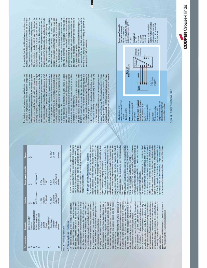
4.3
Sim
ple
syst
ems
- co
ntin
ued
This
con
cern
is c
onfin
ed t
o fix
ed in
duct
ance
and
cap
acita
nce
and
not t
o th
e di
strib
uted
par
amet
ers
of a
cab
le. C
onse
quen
tly
on t
hose
rar
e oc
casi
ons
whe
n BO
TH t
he l
umpe
d in
duct
ance
(th
e su
m o
f Li o
f the
sou
rce
of p
ower
and
the
field
dev
ice)
and
th
e lu
mpe
d ca
paci
tanc
e (th
e su
m o
f Ci o
f the
sou
rce
of p
ower
an
d th
e fie
ld d
evic
e) a
re g
reat
er t
han
1% o
f th
e re
spec
tive
outp
ut p
aram
eter
s of
the
sour
ce o
f pow
er L
o an
d Co
then
the
perm
issi
ble
outp
ut p
aram
eter
s ar
e bo
th to
be
divi
ded
by tw
o.It
shou
ld b
e st
ress
ed t
hat
this
red
uctio
n in
out
put
para
met
ers
is o
nly
appl
icab
le o
n ve
ry r
are
occa
sion
s si
nce
it is
unu
sual
fo
r fie
ld d
evic
es t
o ha
ve B
OTH
indu
ctiv
e an
d ca
paci
tive
inpu
t pa
ram
eter
s w
hich
are
sig
nific
antly
larg
e.Fr
eque
ntly
the
Li a
nd C
i of
a so
urce
of
pow
er a
re n
ot q
uote
d in
the
doc
umen
tatio
n an
d in
the
se c
ircum
stan
ces
it ca
n be
as
sum
ed t
hat
they
are
neg
ligib
le. T
here
is n
o su
gges
tion
that
it
is c
onsi
dere
d ne
cess
ary
to g
o ba
ck a
nd c
heck
the
saf
ety
docu
men
tatio
n on
exi
stin
g in
stal
latio
ns f
or t
his
mos
t re
cent
re
quire
men
t. Ho
wev
er n
ew a
naly
ses
shou
ld t
ake
this
rem
ote
poss
ibili
ty in
to a
ccou
nt.
To s
umm
aris
e, c
heck
tha
t ei
ther
the
lum
ped
capa
cita
nce
or
indu
ctan
ce is
less
than
1%
of t
he re
spec
tive
outp
ut p
aram
eter
s.
If it
is, t
hen
the
orig
inal
cal
cula
tion
is v
alid
. If B
OTH
para
met
ers
are
grea
ter
than
1%
of
the
outp
ut p
aram
eter
s th
en C
o an
d Lo
of t
he s
yste
m s
houl
d be
red
uced
by
a fa
ctor
of t
wo.
If th
is
redu
ctio
n se
ems
to b
e ne
cess
ary
then
go
back
and
che
ck th
e in
form
atio
n us
ed, a
s th
is is
an
unus
ual s
ituat
ion.
Whe
re a
sou
rce
of p
ower
is c
ertifi
ed ‘i
a’ o
r ’ib
’, th
e pe
rmitt
ed
outp
ut p
aram
eter
s Lo
, Co
and
Lo/
Ro a
re d
eriv
ed u
sing
a
fact
or o
f sa
fety
of
1,5.
Whe
n su
ch a
sou
rce
of p
ower
is u
sed
in a
n ‘ic
’ circ
uit t
hen
the
perm
itted
out
put p
aram
eter
s m
ay b
e de
rived
usi
ng a
uni
ty s
afet
y fa
ctor
. Thi
s re
sults
in a
sig
nific
ant
chan
ge, w
hich
usu
ally
rem
oves
the
nece
ssity
to c
onsi
der c
able
pa
ram
eter
s in
det
ail.
Accu
rate
val
ues
can
be a
scer
tain
ed u
sing
th
e m
etho
ds a
nd ta
bles
in th
e ap
para
tus s
tand
ard.
An
acce
ptab
le
cons
erva
tive
tech
niqu
e is
to m
ultip
ly th
e Lo
and
Lo/
Ro b
y tw
o an
d th
e Co
by
thre
e, w
hich
nor
mal
ly re
mov
es a
ny c
once
rn a
bout
ca
ble
para
met
ers.
g)
Chec
k th
at th
e le
vel o
f ins
ulat
ion
from
ear
th is
acc
epta
ble,
or
that
the
syst
em e
arth
ing
requ
irem
ents
are
sat
isfie
d.
If th
ese
crite
ria a
re a
ll sa
tisfie
d th
e co
mpa
tibili
ty o
f th
e tw
o pi
eces
of
appa
ratu
s w
ill h
ave
been
est
ablis
hed.
A c
onve
nien
t w
ay o
f rec
ordi
ng th
e an
alys
is is
to c
reat
e a
tabl
e. Ta
ble
4.1
is a
n ex
ampl
e th
at u
ses
valu
es fr
om th
e ty
pica
l sys
tem
dra
win
g (s
ee
Figu
re 4
.1) a
nd c
ompa
res
the
intri
nsic
ally
saf
e in
terfa
ce a
nd th
e te
mpe
ratu
re tr
ansm
itter
.
4.4
The
use
of s
impl
e ap
para
tus
in s
yste
ms
The
appa
ratu
s st
anda
rd (
IEC
6007
9-11
) di
stin
guis
hes
betw
een
com
plex
ap
para
tus,
w
hich
no
rmal
ly
requ
ires
som
e fo
rm
of
certi
ficat
ion
and
‘sim
ple
appa
ratu
s’ w
hich
is n
ot r
equi
red
to b
e ce
rtifie
d. T
his
dist
inct
ion
is in
tend
ed to
per
mit
the
use
of a
ppar
atus
th
at d
oes
not s
igni
fican
tly a
ffect
the
intri
nsic
saf
ety
of a
sys
tem
, w
ithou
t the
nee
d fo
r ‘th
ird p
arty
’ cer
tifica
tion.
Ther
e is
an
impl
icat
ion
that
it
is p
ossi
ble
to d
emon
stra
te t
hat
sim
ple
appa
ratu
s is
obv
ious
ly s
afe
with
out r
ecou
rse
to th
e de
tail
appl
icat
ion
of th
e re
mai
nder
of t
he s
tand
ard.
For
exa
mpl
e, if
any
cu
rren
t or
vol
tage
lim
iting
com
pone
nts
are
nece
ssar
y th
en t
he
appa
ratu
s is
not
con
side
red
to b
e si
mpl
e. In
pra
ctic
e it
is re
lativ
ely
easy
to
deci
de w
hich
com
pone
nts
are
sim
ple
appa
ratu
s at
the
sy
stem
des
ign
stag
e. If
the
deci
sion
is n
ot e
asy
then
the
appa
ratu
s is
not
sim
ple.
NO
TE
: Alth
ough
it is
not
con
side
red
esse
ntia
l tha
t sim
ple
appa
ratu
s is
cer
tified
by
a th
ird p
arty
, it i
s no
t unu
sual
for s
impl
e ap
para
tus
that
is u
sed
in s
igni
fican
t qua
ntiti
es to
be
certi
fied.
This
is r
eass
urin
g to
the
end
user
and
is a
sig
nific
ant m
arke
ting
adva
ntag
e. In
the
se c
ircum
stan
ces
the
appa
ratu
s is
mar
ked
as
requ
ired
by th
e ap
para
tus
stan
dard
, but
can
be
used
in th
e sa
me
way
as
othe
r sim
ple
appa
ratu
s.Th
e ap
para
tus
stan
dard
impo
ses
limits
of 1
.5V,
100m
A an
d 25
mW
on
the
valu
es g
ener
ated
by
sim
ple
appa
ratu
s, a
nd it
is a
ccep
ted
that
sim
ple
appa
ratu
s ca
n be
add
ed to
an
intri
nsic
ally
saf
e sy
stem
w
ithou
t the
nee
d to
rec
alcu
late
the
safe
ty o
f the
sys
tem
. It m
ust
be u
nder
stoo
d ho
wev
er, t
hat a
ny li
mita
tions
on
sim
ple
appa
ratu
s ap
ply
to th
e co
mbi
natio
n of
all
the
piec
es o
f sim
ple
appa
ratu
s in
a
syst
em. F
or e
xam
ple,
the
use
of o
ne o
r tw
o th
erm
ocou
ples
in a
sy
stem
is p
erm
itted
but
a c
ombi
natio
n of
a la
rge
num
ber u
sed
in
a si
ngle
, ave
rage
tem
pera
ture
circ
uit m
ight
not
mee
t thi
s cr
iterio
n.
The
stan
dard
als
o al
low
s ca
paci
tive
and
indu
ctiv
e co
mpo
nent
s to
be
used
in s
impl
e ap
para
tus,
pro
vide
d th
at th
ese
com
pone
nts
are
incl
uded
in t
he s
yste
m e
valu
atio
n.
It is
not
usu
al t
o in
clud
e in
duct
ors
or c
apac
itors
of s
igni
fican
t siz
e, b
ut th
e si
mpl
e ap
para
tus
conc
ept
does
pe
rmit
the
use
of
smal
l ra
dio-
frequ
ency
(r.
f.)
deco
uplin
g co
mpo
nent
s w
ithou
t un
derta
king
a f
urth
er a
naly
sis
of t
he s
yste
m. A
use
ful r
ule-
of-t
hum
b is
to
ensu
re t
hat
the
tota
l ca
paci
tanc
e an
d in
duct
ance
add
ed to
the
syst
em is
less
than
1%
of
the
resp
ectiv
e ou
tput
par
amet
ers
of th
e so
urce
of p
ower
, in
whi
ch
case
, the
ir ef
fect
can
be
igno
red.
If B
OTH
the
adde
d ca
paci
tanc
e an
d in
duct
ance
, tog
ethe
r w
ith a
ny o
ther
‘lum
ped’
cap
acita
nce
in
the
circ
uit a
re g
reat
er th
an 1
% o
f the
spe
cifie
d ou
tput
par
amet
ers
of th
e so
urce
of p
ower
then
the
perm
itted
out
put p
aram
eter
s m
ust
be h
alve
d, a
s ex
plai
ned
in S
ectio
n 4.
3. T
his
is a
noth
er v
ery
good
re
ason
for e
nsur
ing
that
the
‘ene
rgy
stor
ing’
com
pone
nts
in s
impl
e ap
para
tus
are
kept
sm
all.
It is
als
o ne
cess
ary
to t
empe
ratu
re c
lass
ify s
impl
e ap
para
tus
whe
n it
is in
tend
ed f
or h
azar
dous
are
a. T
he a
ppar
atus
sta
ndar
d al
low
s a
T6 te
mpe
ratu
re c
lass
ifica
tion
for s
witc
hes,
plu
gs, s
ocke
ts
and
term
inal
s us
ed w
ithin
the
ir no
rmal
rat
ing
at a
n am
bien
t te
mpe
ratu
re o
f not
gre
ater
than
40°
C.In
pra
ctic
e, it
is n
ot e
asy
to d
esig
n a
syst
em t
hat
can
be u
sed
with
gas
es re
quiri
ng a
T6
(85°
C) te
mpe
ratu
re c
lass
ifica
tion
and
a T4
(135
°C) c
lass
ifica
tion
is n
orm
ally
the
leve
l ach
ieve
d. In
real
ity,
the
only
gas
list
ed in
the
avai
labl
e do
cum
enta
tion
requ
iring
a T
6 te
mpe
ratu
re c
lass
ifica
tion
is c
arbo
n di
sulfi
de (
CS2).
For
tuna
tely
, th
e us
e of
thi
s ga
s in
indu
stry
is b
ecom
ing
rare
bec
ause
of
its
toxi
city
. A
T4 t
empe
ratu
re c
lass
ifica
tion
is t
here
fore
ade
quat
e no
rmal
ly a
nd a
cla
im o
f T6
is
pred
omin
antly
a m
arke
ting
ploy
ra
ther
than
a re
quire
men
t.Th
e te
mpe
ratu
re c
lass
ifica
tion
of o
ther
pie
ces
of a
ppar
atus
(with
a
surfa
ce a
rea
not l
ess
than
20m
m2 )
norm
ally
rel
ies
on th
e in
put
pow
er b
eing
no
grea
ter
than
1,3
W w
hen
the
max
imum
am
bien
t te
mpe
ratu
re re
quire
d is
40°
C. T
he c
orre
spon
ding
pow
ers
for h
ighe
r am
bien
t tem
pera
ture
s ar
e 1,
2W a
t 60°
C an
d 1W
at 8
0°C.
If th
is ru
le
is n
ot a
pplic
able
then
the
poss
ible
max
imum
sur
face
tem
pera
ture
ha
s to
be
mea
sure
d or
ass
esse
d. If
for a
ny re
ason
it is
not
obv
ious
th
at th
e m
axim
um s
urfa
ce te
mpe
ratu
re is
con
side
rabl
y lo
wer
than
13
5°C
(say
100
°C) t
hen
the
appa
ratu
s is
pro
babl
y no
t sim
ple.
Sim
ple
appa
ratu
s is
usu
ally
iso
late
d fro
m e
arth
. Ho
wev
er,
the
appa
ratu
s st
anda
rd r
equi
res
a 50
0V i
nsul
atio
n te
st a
nd i
f th
e si
mpl
e ap
para
tus
cann
ot m
eet t
his
then
it in
trodu
ces
an e
arth
on
to th
e sy
stem
and
the
syst
em d
esig
n m
ust t
ake
this
into
acc
ount
.A
typi
cal e
xam
ple o
f sim
ple a
ppar
atus
is th
e res
ista
nce t
herm
omet
er
(RTD
) sho
wn
as th
e se
nsor
in th
e ty
pica
l sys
tem
dra
win
g.Th
e RT
D is
a t
empe
ratu
re s
ensi
tive
resi
stor
. It
has
negl
igib
le
indu
ctan
ce (
less
tha
n 4μ
H) b
ecau
se i
t is
bifi
lar
wou
nd a
nd
negl
igib
le c
apac
itanc
e (le
ss th
an 1
0pF)
. The
mat
ched
pow
er fr
om
the
trans
mitt
er t
erm
inal
s is
2,5
mW
, w
hich
is
cons
ider
ably
les
s th
an th
e 25
mW
con
side
red
negl
igib
le fo
r sim
ple
appa
ratu
s.Th
is lo
w le
vel o
f pow
er e
nsur
es th
at th
e te
mpe
ratu
re c
lass
ifica
tion
of th
e RT
D is
det
erm
ined
by
the
tem
pera
ture
bei
ng m
easu
red.
(A
T6 te
mpe
ratu
re s
enso
r mea
surin
g 45
0°C
is a
com
mon
adv
ertis
ing
phen
omen
on.)
The
RTD
does
not
mee
t the
requ
ired
500V
insu
latio
n te
st a
nd c
onse
quen
tly th
is s
ub-c
icui
t is
cons
ider
ed to
be
earth
ed
at th
is p
oint
. The
inst
alla
tion
is s
atis
fact
ory
beca
use
of th
e is
olat
ion
in th
e te
mpe
ratu
re tr
ansm
itter
.Th
e ig
nitio
n en
ergy
of a
gas
dec
reas
es a
t ele
vate
d te
mpe
ratu
res
and
cons
eque
ntly
the
very
low
faul
t vol
tage
and
pow
er a
vaila
ble
to t
he R
TD i
s a
bene
ficia
l fa
ctor
in
ensu
ring
the
safe
ty o
f an
y m
easu
rem
ent o
f hig
h te
mpe
ratu
res.
Tab
le 4
.1 S
impl
e sy
stem
ana
lysi
s
Seq
uen
ce s
tep
P
ara
mete
r
Inte
rfa
ce
Tem
pera
ture
tra
nsm
itte
r
Sys
tem
a)
Le
vel o
f pro
tect
ion
ia
ia
ia
b)
Gas
grou
p
IIC
IIC
IICc)
Te
mpe
ratu
re c
lass
ifica
tion
T4
d)
Ambi
ent t
empe
ratu
re
- 20
°C to
+60
°C
- 40
°C to
+80
°Ce)
Para
met
er c
ompa
rison
Vo
ltage
Uo
: 28V
Ui
: 30V
Cu
rren
t Io
: 93m
A
Ii: 1
20m
A
Pow
er
Po: 6
50m
W
Pi: 1
Wf)
Ca
ble
para
met
ers
Ca
paci
tanc
e
Co: 8
3nF
Ci
: 3nF
Cc
: 80n
F
Indu
ctan
ce
Lo: 3
.05m
H
Li: 1
0μH
Lc
: 3m
H
L/R
ratio
Lo
/Ro:
55μ
H/Ω
Lc
/Rc:
55μ
H/Ω
g)
Is
olat
ion
is
olat
ed
isol
ated
is
olat
ed
Fig
ure
4.2
- R
TD a
nd tr
ansm
itter
sub
-sys
tem
- Cl
assi
ficat
ion
ia II
C-
Cabl
e pa
ram
eter
s 10
00μF
, 3
50m
H-
Earth
ed a
t RTD
Note
: ‘T’
cla
ss d
eter
min
ed
by m
axim
um m
easu
red
tem
pera
ture
.
RTD
Typ
e: 350L (
exa
mp
le)
Pete
r Pty
, Syd
ney,
Aus
tralia
Sim
ple
Appa
ratu
s to
IEC
6007
9-11
Pass
ive
com
pone
nt to
su
bcla
use
5.4a
)
Type
: PS0
61M
axim
um o
pera
ting
tem
pera
ture
450
°CTe
mpe
ratu
re c
lass
ifica
tion
dete
rmin
ed b
y m
axim
umm
easu
red
tem
pera
ture
.
Tem
pera
ture
Tra
nsm
itte
rTy
pe: 365S
(exa
mp
le)
Pan
Inc.
, Bos
ton,
USA
Ex ia
IIC
T4 b
y FU
ML
No. 9
8306
5Am
bien
t tem
pera
ture
–40
°Cto
+80
°C
Term
ina
ls ‘A
’Uo
: 1.0
VIo
: 10
mA
Po: 2
.5 m
WCo
: 100
0μF
Lo: 3
50 m
H
Note
: If c
able
‘x’ b
ecom
es
part
of a
mul
ticor
e, th
en th
is
mul
ticor
e ca
ble
mus
t be
aTy
pe ‘A
’ or ‘
B’, a
s sp
ecifi
edin
IEC
6007
9-14
.
1213

4.5
The
use
of a
ppar
atus
with
‘si
mpl
e ap
para
tus’
in
put d
escr
iptio
nTh
e ot
her c
omm
on u
se fo
r the
sim
ple
appa
ratu
s cl
ause
is to
per
mit
the
use
of c
ertifi
ed a
ppar
atus
with
inpu
t pa
ram
eter
s eq
uiva
lent
to
sim
ple
appa
ratu
s, to
be
adde
d to
an
exis
ting
intri
nsic
ally
saf
e ci
rcui
t with
onl
y a
min
or c
hang
e in
the
docu
men
tatio
n. T
he m
ost
frequ
ent u
ses
of th
is te
chni
que
are
for t
est e
quip
men
t, in
dica
tors
an
d tri
p am
plifi
ers.
A ty
pica
l ex
ampl
e of
thi
s ty
pe o
f ap
plic
atio
n is
the
MTL
531
4 tri
p am
plifi
er w
hich
is
frequ
ently
use
d to
mon
itor
the
4-20
mA
sign
als
from
a t
rans
mitt
er a
s ill
ustra
ted
in F
igur
e 4.
3. T
he in
put
term
inal
s sa
tisfy
the
requ
irem
ents
of s
impl
e ap
para
tus
and
henc
e th
e in
serti
on o
f th
is a
ppar
atus
doe
s no
t re
quire
tha
t th
e sa
fety
an
alys
is o
f th
e ex
istin
g sy
stem
is m
odifi
ed. T
he p
rese
nce
of t
he
trip
ampl
ifier
and
the
fact
that
it is
rega
rded
as
sim
ple
appa
ratu
sis
all
that
nee
ds to
be
reco
rded
.W
here
mor
e th
an o
ne p
iece
of
appa
ratu
s w
ith s
impl
e ap
para
tus
outp
ut c
hara
cter
istic
s is
incl
uded
in a
circ
uit t
hen
care
sho
uld
be
take
n to
ens
ure
that
the
perm
itted
sim
ple
appa
ratu
s pa
ram
eter
s ar
e no
t exc
eede
d. A
dvan
tage
can
som
etim
es b
e ta
ken
of th
e fa
ct
that
the
out
put
volta
ge o
nly
appe
ars
unde
r fa
ult
cond
ition
s an
d
that
it is
per
mitt
ed t
o ap
ply
the
faul
t co
unt
to t
he s
yste
m a
s a
who
le. F
or e
xam
ple
if m
ore
than
one
pie
ce o
f sim
ple
appa
ratu
s is
co
nnec
ted
in th
e ci
rcui
t, th
en it
can
be
argu
ed th
at o
nly
one
piec
e of
app
arat
us is
con
side
red
to fa
il at
any
one
tim
e, a
nd h
ence
onl
y th
e m
ost a
dver
se s
et o
f out
put p
aram
eter
s ne
eds
to b
e co
nsid
ered
. Th
is ty
pe o
f arg
umen
t is
acce
ptab
le in
‘ib’
sys
tem
s bu
t nee
ds to
be
car
eful
ly d
ocum
ente
d. F
or s
uch
an a
rgum
ent
to b
e va
lid f
or
‘ia’
syst
ems
deta
iled
know
ledg
e of
the
der
ivat
ion
of t
he o
utpu
t pa
ram
eter
s is
req
uire
d. T
his
info
rmat
ion
is n
ot u
sual
ly r
eadi
ly
avai
labl
e an
d he
nce
the
tech
niqu
e is
not
nor
mal
ly a
pplic
able
to
‘ia’ s
yste
ms.
If it
is k
now
n th
at th
e ap
para
tus
term
inal
s ar
e pu
rely
re
sist
ive
in n
orm
al o
pera
tion
(as
is fr
eque
ntly
the
case
) the
n an
y nu
mbe
r of t
hese
dev
ices
can
be
inco
rpor
ated
in a
n ‘ic
’ sys
tem
.
5.1
Gene
ral
The
abili
ty to
do
live
mai
nten
ance
on
an in
trins
ical
ly s
afe
syst
em
is a
maj
or b
enefi
t of
the
tec
hniq
ue.
It is
diffi
cult
to t
est
an
inst
rum
ent s
yste
m w
ith th
e po
wer
rem
oved
, and
diffi
cult
to o
btai
n a
mea
ning
ful ‘
gas
clea
ranc
e ce
rtific
ate’
that
cov
ers
the
who
le o
f th
e ar
ea a
ffect
ed b
y a
syst
em. C
onse
quen
tly li
ve w
orki
ng is
ver
y de
sira
ble.
The
re a
re h
owev
er fa
ctor
s, o
ther
than
gas
igni
tion,
that
ha
ve t
o be
con
side
red
whe
neve
r an
inst
rum
ent
syst
em is
tak
en
out
of c
omm
issi
on a
nd c
onse
quen
tly lo
cal s
afet
y pr
actic
es s
uch
as ‘p
erm
its to
wor
k’ h
ave
still
to b
e ob
serv
ed.
5.2
Perm
itted
pra
ctic
es o
n th
e pl
ant
The
desi
gn o
f in
trins
ical
ly s
afe
appa
ratu
s an
d sy
stem
s en
sure
s th
at th
e sh
ort c
ircui
t and
ope
n ci
rcui
t of fi
eld
wiri
ng c
anno
t cau
se
igni
tion
of a
gas
atm
osph
ere.
The
con
cept
of l
ive
mai
nten
ance
use
s th
is fe
atur
e bu
t doe
s no
t ext
end
to c
arry
ing
out d
etai
led
repa
irs;
for e
xam
ple,
repa
iring
prin
ted
circ
uit b
oard
s w
ithin
the
haza
rdou
s ar
eas.
In
prac
tice,
the
per
mis
sibl
e ac
tions
are
res
trict
ed b
y th
e av
aila
ble
tool
s he
nce
deci
ding
wha
t is
perm
issi
ble
is n
ot d
ifficu
lt.
IEC
6007
9-17
rest
ricts
live
‘wor
king
’ to:
i) d
isco
nnec
tion
of,
and
rem
oval
or
repl
acem
ent
of e
lect
rical
ap
para
tus
and
cabl
ing
ii)
adju
stm
ent
of a
ny c
ontro
ls w
hich
is
nece
ssar
y fo
r th
e ca
libra
tion
of th
e el
ectri
cal a
ppar
atus
or s
yste
miii)
rem
oval
and
rep
lace
men
t of
any
plu
g in
com
pone
nts
or
asse
mbl
ies
iv)
use
of a
ny t
est
inst
rum
ents
spe
cifie
d in
the
rel
evan
t do
cum
enta
tion.
Whe
re te
st in
stru
men
ts a
re n
ot s
peci
fied
in th
e re
leva
nt d
ocum
enta
tion,
onl
y th
ose
inst
rum
ents
, whi
ch d
o no
t af
fect
the
intri
nsic
saf
ety
of th
e ci
rcui
t, m
ay b
e us
edv)
any
oth
er m
aint
enan
ce a
ctiv
ity s
peci
fical
ly p
erm
itted
by
the
“rel
evan
t doc
umen
tatio
n”Th
ese
requ
irem
ents
are
in
line
with
the
nor
mal
pra
ctic
e of
m
aint
enan
ce o
n fie
ld m
ount
ed e
quip
men
t an
d he
nce
crea
te n
o pr
oble
m. W
ork
on a
ssoc
iate
d sa
fe a
rea
appa
ratu
s, s
uch
as t
he
intri
nsic
ally
saf
e in
terfa
ce is
rest
ricte
d in
the
sam
e w
ay, e
xcep
t tha
t th
ere
is g
reat
er fr
eedo
m to
ope
rate
on
the
safe
are
a te
rmin
als.
Rece
ntly
dev
elop
ed in
terfa
ces
tend
to o
pera
te fr
om 2
4V s
uppl
ies
and
ther
e is
no
risk
of e
lect
rocu
tion.
How
ever
it is
not
unu
sual
fo
r in
terfa
ces
with
rel
ay o
utpu
ts to
be
switc
hing
hig
her
volta
ges,
w
hich
may
cre
ate
a si
gnifi
cant
sho
ck ri
sk. W
here
this
risk
occ
urs,
ad
equa
te w
arni
ng la
bels
are
requ
ired
and
the
rele
vant
pre
caut
ions
sh
ould
be
take
n du
ring
the
mai
nten
ance
pro
cess
.Th
ere
is n
o ris
k of
a s
igni
fican
t el
ectri
c sh
ock
bein
g re
ceiv
ed
by a
tec
hnic
ian
wor
king
on
an i
ntrin
sica
lly s
afe
circ
uit.
Ther
e is
a h
ypot
hetic
al p
ossi
bilit
y bu
t in
pra
ctic
e th
is i
s no
t a
real
pr
oble
m a
ctio
ns a
re p
erm
itted
, the
y ar
e fre
quen
tly e
mbo
died
in
the
appa
ratu
s ce
rtific
ate
and
man
ufac
ture
r’s i
nstru
ctio
n. T
his
info
rmat
ion
shou
ld b
e m
ade
avai
labl
e to
the
rel
evan
t te
chni
cian
on
the
wor
k sh
eet,
as h
e is
not
like
ly to
hav
e re
ady
acce
ss to
the
certi
ficat
e an
d/or
inst
ruct
ions
. The
app
arat
us m
arki
ng w
ould
car
ry
the
ubiq
uito
us ‘X
’ m
arki
ng b
ut t
his
is a
lmos
t un
iver
sally
app
lied
and
cons
eque
ntly
larg
ely
igno
red.
Mai
nten
ance
and
Rep
air o
f In
trins
ical
ly S
afe
equi
pmen
t5.
3 Pe
rmitt
ed p
ract
ice
in th
e w
orks
hop
The
repa
ir an
d te
stin
g of
in
trins
ical
ly
safe
an
d as
soci
ated
ap
para
tus
shou
ld o
nly
be c
arrie
d ou
t in
favo
urab
le c
ondi
tions
and
by
ade
quat
ely
train
ed te
chni
cian
s. T
he IE
C st
anda
rd IE
C 60
079-
19
prov
ides
som
e gu
idan
ce o
n th
e ap
proa
ch to
repa
ir of
intri
nsic
ally
sa
fe e
quip
men
t.Th
ere
are
alw
ays
prac
tical
and
eco
nom
ic li
mita
tions
on
wha
t is
pr
actic
able
. For
exa
mpl
e, s
hunt
dio
de s
afet
y ba
rrie
rs a
re in
varia
bly
enca
psul
ated
and
not
repa
irabl
e. Is
olat
ing
inte
rface
s ar
e us
ually
in
boxe
s th
at a
re d
ifficu
lt to
ope
n, c
oate
d in
var
nish
and
impo
ssib
le to
te
st in
det
ail w
ithou
t spe
cial
ist t
est e
quip
men
t and
kno
wle
dge
of
the
circ
uit.
In g
ener
al re
plac
emen
t by
an id
entic
al u
nit i
s pr
efer
red
for b
oth
econ
omic
and
saf
ety
reas
ons.
Som
e re
pairs
can
be
carr
ied
out
with
out
affe
ctin
g th
e sa
fety
of
equi
pmen
t an
d, u
sual
ly, i
t is
obv
ious
wha
t lim
itatio
ns a
pply
. For
ex
ampl
e, d
amag
e to
enc
losu
res
does
not
usu
ally
dire
ctly
affe
ct
the
intri
nsic
saf
ety
of a
ppar
atus
and
con
sequ
ently
a re
pair
whi
ch
rest
ores
the
enc
losu
re t
o its
orig
inal
leve
l of
inte
grity
(IP
rat
ing)
is
acc
epta
ble.
The
rep
air
of p
rinte
d ci
rcui
t bo
ards
is s
omet
imes
co
nsid
ered
but
is
usua
lly i
mpr
actic
able
. Re
mov
ing
com
pone
nts
with
out
dam
agin
g th
e bo
ard
is d
ifficu
lt, r
epai
ring
the
coat
ing
on r
eass
embl
y is
mes
sy a
nd m
aint
aini
ng t
he o
rigin
al c
reep
age
and
clea
ranc
e di
stan
ces
may
not
be
poss
ible
. A r
ecen
t fu
rther
co
mpl
icat
ion
is th
at if
lead
free
sol
der
has
been
use
d, th
e us
e of
so
lder
con
tain
ing
lead
usu
ally
resu
lts in
uns
atis
fact
ory
join
ts.
A re
cord
of a
ny re
pairs
sho
uld
be m
aint
aine
d. T
he u
se o
f bef
ore
and
afte
r pho
togr
aphs
(sto
red
digi
tally
) fre
quen
tly s
impl
ifies
the
proc
ess.
5.4
Test
ing
of IS
app
arat
us u
sing
non
-cer
tified
test
app
arat
usTh
ere
are
two
circ
umst
ance
s un
der
whi
ch n
on-c
ertifi
ed t
est
appa
ratu
s is u
sed
to te
st in
trins
ical
ly sa
fe a
nd a
ssoc
iate
d ap
para
tus
and
syst
ems.
One
is w
here
app
arat
us is
test
ed in
the
safe
are
a,
usua
lly d
isco
nnec
ted
from
the
IS
syst
em,
and,
les
s fre
quen
tly,
whe
n ap
para
tus
and
the
syst
em is
test
ed in
the
haza
rdou
s ar
ea
usin
g a
gas
clea
ranc
e ce
rtific
ate.
It is
som
etim
es q
uest
ione
d w
heth
er c
onne
ctin
g no
n-ce
rtifie
d ap
para
tus
durin
g su
ch p
roce
dure
s ca
n re
sult
in t
he i
ntrin
sic
safe
ty o
f th
e ap
para
tus
or s
yste
m b
eing
im
paire
d by
dam
age
to t
he s
afet
y co
mpo
nent
s. I
n th
e pa
st,
test
ing
has
not
requ
ired
any
spec
ial p
reca
utio
ns to
be
take
n to
avo
id th
is p
ossi
bilit
y. T
he
curr
ent
stan
dard
on
insp
ectio
n an
d m
aint
enan
ce I
EC 6
0079
-17
does
not
add
ress
this
que
stio
n, c
onse
quen
tly th
e fo
llow
ing
is o
nly
a co
nsid
ered
opi
nion
and
sho
uld
be re
gard
ed a
s su
ch.
Fig
ure
4.3
MTL
5314
use
d as
mon
itor
5.
Sim
ple
Ap
pa
ratu
s, I
ntr
insi
ca
lly
Sa
fe in
terf
ace,
Trip
Am
plifi
er
MTL5314.
The
Trip
Am
plifi
er c
onne
cts
in s
erie
s w
ith th
e 4/
20
mA
trans
mitt
er c
ircui
t, gi
ving
ala
rm s
igna
ls to
the
safe
are
a vi
a ch
ange
over
rela
ys.
Usin
g th
e Si
mpl
e Ap
para
tus
(Non
-ene
rgy
Stor
ing)
ru
le th
e de
vice
may
be
conn
ecte
d in
ser
ies
with
th
e ha
zard
ous
side
of t
he M
TL55
41.
Cert
ifica
tion
& S
afe
ty P
ara
mete
rs
Term
inal
s 1
and
3 m
eet t
he S
impl
e Ap
para
tus
rule
s ha
ving
out
put p
aram
eter
s:
Uo: 1
.0V,
Io: 8
8mA,
Po:
22m
WCe
rtifie
d [E
Ex ia
] IIC
by
EECS
No. B
AS 9
8 AT
EX 7
136
Tam
b –2
0°C
to +
60°C
Um: 2
50 V
1415

5.4
Test
ing
of IS
app
arat
us u
sing
non
-cer
tified
test
app
arat
us -
con
tinue
d A
rele
vant
poi
nt is
tha
t du
ring
the
man
ufac
turin
g of
intri
nsic
ally
sa
fe p
rodu
cts,
the
equ
ipm
ent
used
for
bot
h op
erat
iona
l an
d sa
fety
tes
ting
relie
s on
goo
d en
gine
erin
g pr
actic
e an
d re
gula
r in
spec
tion
to a
chie
ve a
dequ
ate
safe
ty.
It is
not
sub
ject
to
third
pa
rty c
ertifi
catio
n or
any
sim
ilar c
onst
rain
ts. T
he a
ppar
atus
des
ign
stan
dard
s ad
dres
s so
me
of t
he m
ore
obvi
ous
risks
, suc
h as
the
ch
argi
ng o
f bat
terie
s, b
ut d
o no
t mak
e an
y ot
her r
ecom
men
datio
ns
to c
over
less
freq
uent
ly u
sed
faci
litie
s.Th
e fa
ctor
s, w
hich
just
ify th
e us
e of
con
vent
iona
l tes
t equ
ipm
ent
whe
n w
orki
ng o
n in
trins
ical
ly s
afe
appa
ratu
s, a
re:
a) R
epai
r and
mai
nten
ance
sho
uld
only
be
carr
ied
out b
y ‘sk
illed
pe
rson
nel’.
Su
ch
pers
onne
l sh
ould
be
ad
equa
tely
tra
ined
to
rec
ogni
se w
heth
er a
mis
take
cou
ld h
ave
caus
ed d
amag
e,
whi
ch m
ight
lead
to a
dan
gero
us s
ituat
ion,
and
be
capa
ble
of
taki
ng a
ny n
eces
sary
cor
rect
ive
actio
n.b
) Te
st e
quip
men
t sh
ould
be
chec
ked
to e
nsur
e th
at i
t is
op
erat
iona
l be
fore
con
nect
ing
it to
the
app
arat
us.
Parti
cula
r ca
re s
houl
d be
take
n to
ens
ure
that
any
var
iabl
e co
ntro
ls, s
uch
as o
utpu
t vol
tage
and
cur
rent
lim
its o
n po
wer
sup
plie
s, a
re s
et
to th
e co
rrec
t val
ues
befo
re m
akin
g th
e in
terc
onne
ctio
n. T
he te
st
equi
pmen
t sho
uld
be c
heck
ed a
t the
end
of t
he te
st. S
ince
the
test
equ
ipm
ent i
s on
ly c
onne
cted
for a
sho
rt tim
e th
e pr
obab
ility
of
it fa
iling
in a
way
that
can
cau
se a
pot
entia
lly h
azar
dous
faul
t in
that
tim
e is
acc
epta
bly
low
.c) T
he a
ppar
atus
sho
uld
be fu
nctio
ning
cor
rect
ly a
nd b
e fre
e of
m
echa
nica
l dam
age
at th
e en
d of
the
test
or r
e-ca
libra
tion.
It is
po
ssib
le th
at a
saf
ety
com
pone
nt fa
ilure
will
not
affe
ct o
pera
tiona
l ca
pabi
lity
but u
sual
ly a
n op
erat
iona
l fai
lure
will
als
o oc
cur.
d)
The
mor
e co
mpl
ex o
pera
tions
suc
h as
re-
prog
ram
min
g an
d do
wnl
oadi
ng o
f ap
para
tus
mem
orie
s ar
e no
rmal
ly d
one
usin
g te
st r
igs
with
spe
cific
plu
gs a
nd s
ocke
ts a
nd h
ence
the
prob
abili
ty o
f inc
orre
ct c
onne
ctio
n is
redu
ced.
e)
Test
eq
uipm
ent
that
sa
tisfie
s th
e pe
rson
nel
safe
ty
requ
irem
ents
of I
EC 6
1010
, is
not l
ikel
y to
pro
duce
cur
rent
s or
vo
ltage
s, w
hich
will
dam
age
safe
ty c
ompo
nent
s. F
or e
xam
ple
a fu
nctio
ning
osc
illos
cope
with
hig
h im
peda
nce
prob
es i
s ex
trem
ely
unlik
ely
to c
ause
a p
robl
em.
Ther
e ar
e so
me
oper
atio
ns w
hich
do
requ
ire s
peci
al c
are,
of w
hich
th
e m
ost
obvi
ous
is h
igh
volta
ge in
sula
tion
test
ing.
Thi
s sh
ould
on
ly b
e do
ne w
hen
a sp
ecia
l wor
k in
stru
ctio
n is
ava
ilabl
e.In
pra
ctic
e su
ch te
sts
are
best
avo
ided
and
if a
n in
sula
tion
test
is
thou
ght t
o be
nec
essa
ry it
sho
uld
be d
one
at a
low
vol
tage
. It i
s ge
nera
lly a
ccep
ted
that
the
test
ing,
cal
ibra
tion
and
prog
ram
min
g of
intri
nsic
ally
safe
app
arat
us in
a sa
fe a
rea,
or u
nder
gas
clea
ranc
e co
nditi
ons
by a
com
pete
nt p
erso
n us
ing
conv
entio
nal h
igh
qual
ity
test
equ
ipm
ent d
oes
not i
nval
idat
e its
intri
nsic
saf
ety
certi
ficat
ion.
5.5
Re-u
se o
f int
rinsi
cally
saf
e fie
ld d
evic
esTh
e qu
estio
n is
som
etim
es r
aise
d as
to
whe
ther
int
rinsi
cally
sa
fe a
ppar
atus
whi
ch h
as b
een
used
in
circ
uits
whi
ch a
re n
ot
intri
nsic
ally
saf
e, s
uch
as n
on-in
cend
ive
or s
afe
area
circ
uits
can
su
bseq
uent
ly b
e us
ed in
intri
nsic
ally
saf
e ci
rcui
ts. T
he p
erce
ived
pr
oble
m i
s th
at u
se i
n th
e no
n-in
trins
ical
ly s
afe
circ
uits
cou
ld
caus
e da
mag
e, w
hich
is n
ot s
elf-
reve
alin
g bu
t wou
ld r
educ
e th
e le
vel o
f pro
tect
ion
offe
red
by th
e or
igin
al c
ertifi
catio
n. T
he re
leva
nt
IEC
stan
dard
s do
not
giv
e an
y gu
idan
ce o
n th
is to
pic
and
henc
e th
e fo
llow
ing
text
is o
nly
a co
nsid
ered
opi
nion
, whi
ch m
ay n
ot b
e un
iver
sally
acc
epte
d.Th
e qu
estio
n no
rmal
ly a
rises
bec
ause
it
is c
omm
on p
ract
ice
on m
ost
petro
chem
ical
ins
talla
tions
to
purc
hase
a s
ingl
e ty
pe
of in
stru
men
t, fo
r ex
ampl
e a
pres
sure
tra
nsm
itter
, for
use
in a
ll lo
catio
ns o
n a
plan
t. An
intri
nsic
ally
saf
e tra
nsm
itter
can
then
be
used
on
a te
mpo
rary
inst
alla
tion
in a
saf
e ar
ea in
a c
onve
ntio
nal
safe
are
a lo
op, a
nd a
fter
som
e tim
e be
ret
urne
d to
the
sto
re a
s a
spar
e in
stru
men
t. Fr
om th
e st
ore
it co
uld
be u
sed
to r
epla
ce a
de
fect
ive
inst
rum
ent i
n an
intri
nsic
ally
saf
e lo
op.
It ca
n be
ass
umed
that
the
repl
acin
g in
stru
men
t is
func
tiona
l, an
d no
t mec
hani
cally
dam
aged
(the
maj
ority
of i
nstru
men
t tec
hnic
ians
w
ould
che
ck t
his
in t
he w
orks
hop
befo
re p
uttin
g th
e in
stru
men
t in
the
stor
es a
s a
spar
e) a
nd th
eref
ore
the
conc
ern
is th
at th
ere
is s
ome
faul
t w
hich
red
uces
the
saf
ety
inte
grity
but
doe
s no
t af
fect
the
ope
ratio
n of
the
inst
rum
ent.
Alm
ost
all f
aults
fro
m a
n ex
tern
al s
ourc
e w
ould
cau
se s
uffic
ient
dam
age
to th
e ap
para
tus
for
it to
mal
func
tion,
rat
her
than
cau
se t
he c
onse
rvat
ivel
y ra
ted
safe
ty c
ompo
nent
s to
fail
to d
ange
r w
ithou
t dam
agin
g an
y ot
her
com
pone
nts.
Thi
s ty
pe o
f und
etec
ted
failu
re is
just
pos
sibl
e bu
t is
suffi
cien
tly im
prob
able
to
be ig
nore
d. In
the
par
ticul
ar c
ase
of a
no
n-in
cend
ive
inst
alla
tion
then
the
sele
ctio
n of
app
arat
us, a
nd th
e in
stal
latio
n co
de fo
llow
ed fu
rther
red
uce
the
prob
abili
ty o
f the
IS
appa
ratu
s be
ing
stre
ssed
.Th
ere
are
a nu
mbe
r of
circ
umst
ance
s w
here
a v
ery
sim
ilar
risk
occu
rs, a
nd t
he r
isk
is c
onsi
dere
d ac
cept
able
. A v
ery
clea
r ex
ampl
e is
that
the
IEC
stan
dard
on
insp
ectio
n an
d m
aint
enan
ce
(IEC
6007
9-17
), pe
rmits
the
use
of
non-
certi
fied
test
equ
ipm
ent
unde
r ‘g
as c
lear
ance
cer
tifica
te’
cond
ition
s. S
imila
r ris
ks a
re
acce
pted
dur
ing
faul
t-fin
ding
pro
cedu
res i
n in
stru
men
t wor
ksho
ps.
Ther
e ar
e al
so s
igni
fican
t ris
ks o
f suc
h fa
ults
occ
urrin
g du
ring
the
repa
ir pr
oedu
res
perm
itted
by
the
sam
e st
anda
rd o
n re
pairi
ng th
is
type
of a
ppar
atus
. The
test
equ
ipm
ent u
sed
in th
e fin
al s
tage
s of
m
anuf
actu
ring
of IS
equ
ipm
ent i
s no
t des
igne
d to
be
faul
t tol
eran
t an
d co
uld
prod
uce
unde
tect
ed f
aults
. The
se r
isks
illu
stra
te t
he
poin
t tha
t whe
re a
risk
is s
mal
l it c
an b
e, a
nd is
, acc
epte
d.W
ith t
he r
ecen
t in
trodu
ctio
n of
the
‘ic
’ co
ncep
t, th
is q
uest
ion
beco
mes
mor
e re
leva
nt to
intri
nsic
ally
saf
e ci
rcui
ts; f
or e
xam
ple,
th
e us
e of
an
‘ia’ c
ertifi
ed tr
ansm
itter
in a
n ‘ia
’ sys
tem
afte
r it h
as
been
use
d in
an
‘ic’ s
yste
m m
ay b
e qu
estio
ned.
The
que
stio
n of
th
e tra
nsfe
r of a
ppar
atus
from
an
‘ib’ s
yste
m to
an
‘ia’ s
yste
m h
as
neve
r bee
n ra
ised
as
far a
s is
kno
wn.
The
conc
lusi
on is
ther
efor
e th
at th
e sa
fety
sta
tus
of a
fiel
d de
vice
is
not c
hang
ed p
rovi
ded
that
the
devi
ce is
bot
h fu
nctio
ning
cor
rect
ly
and
not
mec
hani
cally
dam
aged
afte
r be
ing
used
in a
ny t
ype
of
circ
uit.
If th
ese
two
requ
irem
ents
are
met
, the
fiel
d de
vice
can
be
used
in a
n in
trins
ical
ly s
afe
circ
uit w
ithou
t fur
ther
con
side
ratio
n.
6.1
Gene
ral
A nu
mbe
r of
fine
ly d
ivid
ed m
ater
ials
can
be
igni
ted
to c
reat
e an
ex
plos
ion
whe
n th
ey f
orm
a c
loud
in a
ir. A
lmos
t al
l org
anic
and
fo
od p
rodu
ct d
usts
tog
ethe
r w
ith m
etal
lic d
ust
can
read
ily b
e ig
nite
d. D
ust e
xplo
sion
s ar
e ge
nera
lly m
ore
diffi
cult
to in
itiat
e th
an
gas/
air
expl
osio
ns b
ut c
an b
e de
vast
atin
g. T
he i
nitia
l ex
plos
ion
frequ
ently
dis
turb
s an
d en
train
s la
yere
d du
st t
o cr
eate
one
or
mor
e se
cond
ary
expl
osio
ns, t
hus
crea
ting
a ro
lling
exp
losi
on a
nd
exte
nsiv
e da
mag
e.Du
st e
xplo
sion
s ca
n be
ini
tiate
d by
ele
ctric
al s
park
s or
by
hot
surfa
ces.
The
re a
re n
umer
ous
fact
ors,
whi
ch i
nflue
nce
igni
tion
ener
gy a
nd te
mpe
ratu
re o
f a p
artic
ular
mat
eria
l. Fo
r exa
mpl
e th
e ai
r to
par
ticle
rat
io,
the
parti
cle
size
, hu
mid
ity,
and
the
mel
ting
tem
pera
ture
of t
he m
ater
ial.
Note
: Fo
r th
ose
requ
iring
a
com
preh
ensi
ve
refe
renc
e ‘D
ust
expl
osio
ns in
the
proc
ess
indu
strie
s’ b
y Ro
lf. K
. Eck
hoff
publ
ishe
d by
Bu
tterw
orth
Hei
nem
ann.
ISBN
0 7
506
3270
4 is
reco
mm
ende
d.Th
e ig
nitio
n en
ergy
of a
dus
t/air
mix
ture
is h
igh
com
pare
d w
ith th
at
of a
gas
/air
mix
ture
. For
exa
mpl
e, s
ome
sens
itive
mat
eria
ls s
uch
as ru
bber
, sul
fur a
nd fi
ne w
ood
dust
requ
ire 1
to 1
0 m
J w
hile
less
se
nsiti
ve m
ater
ials
, suc
h as
cof
fee,
requ
ire m
ore
than
500
mJ.
Ther
e is
som
e co
ncer
n th
at s
ome
very
fine
ly d
ivid
ed p
artic
les,
for
exam
ple
thos
e as
soci
ated
with
nan
o-te
chno
logy
, may
hav
e ev
en
low
er ig
nitio
n en
ergi
es. C
onse
quen
tly, t
he d
ecis
ion
has
been
mad
e to
use
the
IIB
gas
as t
he t
est
mix
ture
(ig
nitio
n en
ergy
80μ
J) f
or
intri
nsic
ally
safe
app
arat
us fo
r use
in d
ust a
tmos
pher
es. T
his i
s a ve
ry
cons
erva
tive
deci
sion
but
pre
sent
s ve
ry li
ttle
oper
atio
nal d
ifficu
lty.
The
curre
nt s
tate
of k
now
ledg
e on
the
spar
k ig
nitio
n ch
arac
teris
tics
of d
usts
and
the
diffi
culty
of c
reat
ing
a sa
tisfa
ctor
y te
st a
ppar
atus
fo
r dus
t atm
osph
eres
just
ifies
a c
autio
us p
rude
nt d
ecis
ion.
The
maj
or p
robl
em i
n du
st a
tmos
pher
es i
s th
e po
ssib
ility
of
ther
mal
igni
tion.
The
re a
re tw
o co
mm
on m
echa
nism
s, o
ne is
the
igni
tion
of a
dus
t clo
ud b
y a
hot b
ody
and
the
othe
r is
the
crea
tion
of s
mou
lder
ing
in a
laye
r of d
ust o
n a
hot s
urfa
ce.
The
min
imum
ign
ition
tem
pera
ture
of
the
maj
ority
of
dust
s lie
s be
twee
n 30
0°C
and
600°
C. S
ome
dust
s do
igni
te a
t lo
wer
te
mpe
ratu
res,
for
exa
mpl
e fin
ely
divi
ded
sulfu
r ha
s a
min
imum
ig
nitio
n te
mpe
ratu
re o
f 240
°C. I
t is
quite
diffi
cult
to g
ener
ate
thes
e te
mpe
ratu
res
in a
dus
t clo
ud w
ith th
e po
wer
leve
ls p
erm
itted
by
a IIB
gas
cla
ssifi
catio
n an
d he
nce
the
prob
abili
ty o
f ig
nitio
n of
a
dust
clo
ud b
y in
trins
ical
ly s
afe
appa
ratu
s is
qui
te lo
w a
nd n
ot th
e m
ajor
pro
blem
.
Intri
nsic
Saf
ety
and
Dust Th
e pr
inci
pal d
ifficu
lty is
the
pos
sibi
lity
of c
ausi
ng s
mou
lder
ing
with
in a
dus
t lay
er, w
hich
whe
n di
stur
bed
burs
ts in
to fl
ames
and
in
itiat
es a
n ex
plos
ion.
The
mec
hani
sm o
f cau
sing
sm
ould
erin
g is
co
mpl
ex b
ut c
an b
e si
mpl
ified
into
kee
ping
the
dust
bel
ow it
s ‘gl
ow
tem
pera
ture
’. Th
e m
ajor
ity o
f mat
eria
ls h
ave
a gl
ow te
mpe
ratu
re,
rang
ing
from
250
°C t
o 50
0°C,
tha
t is
low
er t
han
the
min
imum
ig
nitio
n te
mpe
ratu
re o
f the
cor
resp
ondi
ng d
ust c
loud
.Th
ere
are
also
som
e fla
mm
able
dus
t lay
ers
that
hav
e th
e fo
rtuna
te
char
acte
ristic
of
mel
ting
befo
re a
ttain
ing
thei
r th
eore
tical
glo
w
tem
pera
ture
and
con
sequ
ently
they
do
not c
reat
e th
is ig
nitio
n ris
k (fo
r exa
mpl
e po
lyst
yren
e).
6.2
Intr
insi
cally
saf
e ap
para
tus
and
dust
sIn
trins
ical
ly s
afe
appa
ratu
s ce
rtifie
d fo
r us
e in
haz
ardo
us g
as
atm
osph
eres
has
bee
n us
ed to
ens
ure
safe
ty in
dus
t atm
osph
eres
fo
r m
any
year
s. C
urre
ntly
a g
reat
dea
l of
activ
ity is
tak
ing
plac
e to
form
alis
e th
e re
quire
men
ts fo
r app
arat
us s
peci
fical
ly fo
r use
in
dust
s. A
n ap
para
tus
stan
dard
IEC
6124
1-11
is n
ow p
ublis
hed.
The
ul
timat
e in
tent
ion
is to
am
alga
mat
e th
e du
st a
nd g
as re
quire
men
ts
with
in t
he r
elev
ant
IEC
stan
dard
s bu
t th
is w
ill t
ake
a nu
mbe
r of
ye
ars
(five
?).
Even
tual
ly t
here
will
be
thre
e le
vels
of
prot
ectio
n ‘ia
D’, ‘
ibD’
, and
‘icD
’ cor
resp
ondi
ng to
the
equi
vale
nt g
as le
vels
of
prot
ectio
n (s
ee Ta
ble
6.1)
. The
inte
ntio
n is
that
‘iaD
’ equ
ipm
ent w
ill
achi
eve
the
‘ver
y hi
gh’ l
evel
of p
rote
ctio
n re
quire
d by
equ
ipm
ent
desi
gnat
ed a
s ‘E
PL D
a’ (w
here
EPL
mea
ns ‘E
quip
men
t Pro
tect
ion
Leve
l’ as
defi
ned
in I
EC60
079-
0).
‘ibD’
with
a ‘
high
’ le
vel
of
prot
ectio
n w
ill a
chie
ve a
n ‘E
PL D
b’ a
nd ‘i
cD’ w
ith a
n ‘e
nhan
ced’
le
vel o
f pro
tect
ion
will
be
‘EPL
Dc’
.
Tab
le 6
.1 -
Com
paris
on o
f diff
eren
t lev
els
of ri
sk
6.
Leve
l of
C
ou
nta
ble
Leve
l of
E
qu
ipm
en
t
ATE
X
Norm
al
pro
tecti
on
fa
ult
s
risk
P
rote
cti
on
ca
teg
ory
zo
ne o
f u
se
Leve
l -
EP
L
iaD
2
ve
ry h
igh
Da
1
20
ibD
1
hi
gh
Db
2
21ic
D
0
cons
ider
able
Dc
3
22
MTL4850 H
AR
T® M
ultip
lexe
r.
1617

6.2
Intr
insi
cally
saf
e ap
para
tus
and
dust
s -
cont
inue
d Th
e ris
k of
spar
k ig
nitio
n is
avo
ided
by s
atis
fyin
g th
e re
quire
men
ts fo
r ap
para
tus
inte
nded
for u
se in
IIB
gase
s To
avo
id th
e ris
k of
ther
mal
ig
nitio
n th
e pr
efer
red
tech
niqu
e fo
r app
arat
us, w
hich
is in
tend
ed to
be
loca
ted
in th
e ha
zard
ous
area
, is
to e
xclu
de th
e du
st b
y us
ing
an IP
6X
encl
osur
e or
by
enca
psul
atio
n. T
his
invo
lves
det
erm
inin
g a
max
imum
tem
pera
ture
rise
of t
he e
xpos
ed s
urfa
ce, w
hich
in th
e ca
se o
f mos
t int
rinsi
cally
saf
e ap
para
tus
will
be
very
sm
all.
The
pref
eren
ce f
or a
dus
t tig
ht e
nclo
sure
is
beca
use
the
‘dus
t fra
tern
ity’ h
as im
plic
it fa
ith in
this
tech
niqu
e. It
can
be
argu
ed th
at
the
rest
rictio
n of
the
avai
labl
e po
wer
is a
mor
e re
liabl
e te
chni
que
as it
is le
ss p
rone
to m
aint
enan
ce e
rror
s.Th
ere
is a
n ex
empt
ion
to th
e en
clos
ure
rule
for
appa
ratu
s th
at is
di
fficu
lt to
ope
rate
ins
ide
an e
nclo
sure
, su
ch a
s so
me
sens
ors.
In
thes
e ci
rcum
stan
ces
the
pow
er le
vel i
s re
stric
ted
to a
void
the
poss
ibili
ty o
f tem
pera
ture
igni
tion
(750
mW
at 4
00°C
), In
pra
ctic
e al
l in
trins
ical
ly
safe
as
soci
ated
ap
para
tus
such
as
ba
rrie
rs
and
isol
ated
int
erfa
ces,
whi
ch a
re I
IC o
r IIB
cer
tified
for
gas
es
are
suita
ble
for
use
in in
trins
ical
ly s
afe
syst
ems.
It is
has
bee
n co
mm
on p
ract
ice
for
seve
ral y
ears
for
inte
rface
s to
be
certi
fied
for b
oth
gas
and
dust
app
licat
ions
. For
exa
mpl
e, th
e cu
rren
t MTL
ra
nge
of b
arrie
rs (
MTL
7700
) an
d is
olat
ors
(MTL
4500
/550
0) a
re
certi
fied
for b
oth
gas
and
dust
app
licat
ions
in a
ccor
danc
e w
ith th
e re
quire
men
ts o
f the
ATE
X Di
rect
ive
and
FM s
tand
ards
. The
des
ign
of in
trins
ical
ly s
afe
appa
ratu
s fo
r use
in d
usts
is th
e su
bjec
t mat
ter
of P
art 1
1 of
IEC
6124
1
6.3
Risk
ana
lysi
sAn
alys
ing
the
risk
asso
ciat
ed w
ith a
flam
mab
le d
ust d
iffer
s fro
m
the
anal
ysis
of a
gas
risk
larg
ely
beca
use
dust
doe
s no
t dis
pers
e in
the
sam
e w
ay a
s a
gas,
it h
as to
be
rem
oved
.A
deci
sion
was
mad
e so
me
year
s ago
to o
nly a
rea
class
ify d
ust c
loud
s an
d to
trea
t the
pos
sibilit
y of
a s
mou
lder
ing
dust
laye
r as
a so
urce
of
igni
tion.
(a d
ecisi
on la
rgel
y in
fluen
ced
by th
e AT
EX D
irect
ives)
.Th
e ar
ea c
lass
ifica
tion
of d
ust
clou
ds f
ollo
ws
the
patte
rn o
f ga
s cl
ouds
. Zo
ne 2
0 co
rres
pond
s to
Zon
e 0
(whe
re t
he h
azar
d is
pr
esen
t co
ntin
uous
ly o
r fo
r lo
ng p
erio
ds)
Zone
21
to Z
one1
and
Zo
ne 2
2 to
Zon
e 2
as t
he p
roba
bilit
y of
the
dus
t cl
oud
bein
g pr
esen
t red
uces
.Ar
ea c
lass
ifica
tion
of d
usts
is th
e su
bjec
t mat
ter o
f Par
t 10
of IE
C 61
241.
If
the
com
bina
tion
of a
rea
clas
sific
atio
n an
d so
urce
s of
ig
nitio
n is
pur
sued
too
dili
gent
ly t
his
can
crea
te s
ome
tortu
ous
thin
king
. For
tuna
tely
, the
app
licat
ion
of a
littl
e pr
agm
atic
com
mon
se
nse
solv
es m
ost i
nstru
men
tatio
n pr
oble
ms.
For e
xam
ple,
if a
tem
pera
ture
sen
sor i
s bu
ried
in a
mou
nd o
f gra
in
for a
con
side
rabl
e le
ngth
of t
ime,
then
it is
reas
onab
le to
use
a le
vel
of p
rote
ctio
n ‘ia
D’ s
ince
dec
idin
g th
e ar
ea c
lass
ifica
tion
is d
ifficu
lt an
d if
the
grai
n is
sm
ould
erin
g it
will
pro
babl
y bu
rst
into
flam
e w
hen
dist
urbe
d an
d co
uld
poss
ibly
exp
lode
. As
it is
not
exp
ensi
ve
to m
ake
the
syst
em ‘
iaD’
, th
is b
ecom
es t
he o
bvio
us s
olut
ion.
Ho
wev
er i
f a
tem
pera
ture
mon
itor
is m
easu
ring
tem
pera
ture
in
a lo
catio
n w
here
it
is i
nfre
quen
tly c
over
ed b
y du
st a
nd c
an b
e re
adily
and
fre
quen
tly c
lean
ed t
hen
a le
vel o
f pr
otec
tion
‘icD’
is
adeq
uate
. It m
ight
stil
l be
expe
dien
t to
use
‘iaD’
equ
ipm
ent b
ut it
is
not
ess
entia
l to
do s
o.
6.4
Why
use
intr
insi
c sa
fety
?Th
e pr
inci
pal
reas
on f
or u
sing
int
rinsi
c sa
fety
is
beca
use
it is
es
sent
ially
a lo
w p
ower
tech
niqu
e. C
onse
quen
tly, t
he ri
sk o
f ign
ition
is
min
imis
ed, a
nd a
dequ
ate
safe
ty c
an b
e ac
hiev
ed w
ith a
leve
l of
confi
denc
e th
at is
not
alw
ays
achi
eved
by
othe
r tec
hniq
ues.
It is
diffi
cult
to a
sses
s th
e te
mpe
ratu
re r
ise,
whi
ch c
an o
ccur
if
equi
pmen
t is
imm
erse
d in
a d
ust b
ecau
se o
f the
man
y (fr
eque
ntly
un
pred
icta
ble)
fac
tors
, w
hich
det
erm
ine
the
tem
pera
ture
ris
e w
ithin
the
dust
laye
r. Th
e sa
fest
tech
niqu
e is
ther
efor
e to
res
trict
th
e av
aila
ble
pow
er t
o th
e lo
wes
t pr
actic
al le
vel.
A m
ajor
fac
tor
in f
avou
r of
int
rinsi
c sa
fety
is
that
the
pow
er l
evel
und
er f
ault
cond
ition
s is
con
trolle
d by
the
syst
em d
esig
n an
d do
es n
ot re
ly o
n th
e le
ss w
ell-s
peci
fied
limita
tion
of fa
ult p
ower
.In
trins
ic sa
fety
als
o ha
s the
adv
anta
ge th
at th
e po
ssib
ility
of i
gniti
on
from
imm
erse
d or
dam
aged
wiri
ng is
min
imis
ed. I
t is
desi
rabl
e to
be
abl
e to
do
‘live
mai
nten
ance
’ on
an
inst
rum
ent
syst
em, a
nd
the
use
of th
e in
trins
ical
ly s
afe
tech
niqu
e pe
rmits
this
with
out t
he
nece
ssity
of s
peci
al ‘d
ust f
ree’
cer
tifica
tes.
The
re is
a n
eed
to c
lear
la
yers
of d
ust c
aref
ully
and
to a
void
con
tam
inat
ion
of th
e in
terio
r of
appa
ratu
s du
ring
mai
nten
ance
but
this
is a
ppar
ent t
o an
y tra
ined
te
chni
cian
. (Th
ere
is n
o si
gnifi
cant
pos
sibi
lity
of a
per
son,
in a
dus
t cl
oud
that
can
be
igni
ted,
sur
vivi
ng w
ithou
t bre
athi
ng a
ppar
atus
).To
sum
mar
ise,
int
rinsi
c sa
fety
is
the
pref
erre
d te
chni
que
for
inst
rum
enta
tion
whe
re d
ust i
s th
e ha
zard
bec
ause
:•
the
inhe
rent
saf
ety
of in
trins
ic s
afet
y gi
ves
the
grea
test
as
sura
nce
of s
afet
y an
d re
mov
es c
once
rn o
ver o
verh
eatin
g
of e
quip
men
t and
cab
les
• th
e in
stal
latio
n ru
les
are
clea
rly s
peci
fied
and
the
syst
em
desi
gn e
nsur
es th
at a
ll sa
fety
asp
ects
are
cov
ered
• li
ve m
aint
enan
ce is
per
mitt
ed•
equ
ipm
ent i
s av
aila
ble
to s
olve
the
maj
ority
of p
robl
ems
The
prin
cipa
l rea
son
for
usin
g in
trin
sic
safe
ty
is
bec
ause
it is
ess
entia
lly a
low
pow
er t
echn
ique
, c
onse
quen
tly t
he r
isk
of ig
nitio
n is
min
imis
ed.
1819

Intr
insi
c sa
fety
(IS
) is
ola
tors
fo
r haza
rdous
are
a
inte
rfaci
ng
MTL
4500
/MTL
5500
SER
IES
The
DIN
-rail
mounting M
TL5
500 S
erie
s m
eets
the
need
s of
the
IS in
terfa
ce m
arke
t for
"ap
plic
atio
n fo
cuss
ed"
proj
ects,
ran
ging
fro
m s
ingl
e in
strum
ent
loop
s, th
roug
h to
fully
equ
ippe
d ca
bine
ts, a
cros
s al
l in
dustr
ies
whe
re h
azar
dous
are
as e
xist.
The
MTL
55
00 c
lips
quic
kly
ont
o D
IN r
ail,
so i
t is
com
patib
le w
ith t
he i
ndus
try-st
anda
rd m
ount
ing
syste
m.
Wiri
ng i
s si
mpl
ified
by
plug
-in s
afe-
and
ha
zard
ous-a
rea
conn
ecto
rs,
and
a po
wer
pl
ug
whi
ch a
ccep
ts a
pow
er b
us;
it al
l le
ads
to q
uick
er
inse
rtion
, fe
wer
wiri
ng e
rror
s an
d tro
uble
-free
, tid
ier
insta
llatio
ns.
Line
fault d
etec
tion (
LFD
) fa
cilit
ies
are
prov
ided
ac
ross
the
ran
ge o
f I/
O f
unct
ions
; on
the
sw
itch/
prox
imity
det
ecto
rs,
the
MTL
4523
/552
3 so
leno
id/
alar
m d
river
s an
d th
e is
olat
ing
driv
ers.
Ana
logu
e in
put u
nits
such
as
the
MTL
4541
/554
1 pr
ovid
e lin
e fa
ult d
etec
tion
by re
peat
ing
o/c
or s
/c c
urre
nts
to th
e sa
fe-a
rea
cont
rol s
yste
m.
Statu
s LE
Ds,
con
figur
atio
n sw
itche
s an
d po
rts
are
loca
ted
on th
e to
p or
sid
e of
indi
vidu
al m
odul
es,
as a
ppro
pria
te, f
or e
asy
acce
ss.
Both
new
se
ries
ha
ve
bee
n
des
igned
fo
r co
mpatiblit
y
with
earl
ier
model
s.
The
MTL
4500
se
ries
prov
ides
pl
ug-re
plac
emen
ts
for
earli
er M
TL40
00 s
erie
s un
its,
whi
le t
he M
TL55
00
mod
els
can
easi
ly r
epla
ce M
TL50
00 s
erie
s un
its.
Each
of
fer
the
late
st in
m
oder
n te
chno
logy
an
d ef
ficie
ncy
with
out c
ompr
omis
e.
MTL
's
late
st
gen
eration
of
IS
inte
rface
s ut
ilise
s an
in
nova
tive
"One
-Cor
e"
tech
nolo
gy
to
ensu
re
the
high
est
qual
ity
and
avai
labi
lity
whi
le
mai
ntai
ning
m
axim
um
flexi
bilit
y at
lo
wes
t co
st.
Inco
rpor
atin
g ad
vanc
ed c
ircui
t des
ign,
a c
omm
on s
et
of c
ompo
nent
s an
d in
nova
tive
isol
atin
g tra
nsfo
rmer
co
nstru
ctio
n,
they
ac
hiev
e a
sign
ifica
nt
redu
ctio
n in
po
wer
co
nsum
ptio
n w
hile
in
crea
sing
ch
anne
l pa
ckin
g de
nsiti
es.
The
com
pact
, 16
mm
wid
e de
sign
redu
ces
wei
ght a
nd g
ives
exc
eptio
nally
hig
h pa
ckin
g de
nsity
. Th
ey
build
on
th
e
prov
en
succ
ess
of
the
MTL
2000
, 30
00,
4000
and
500
0 Se
ries
to
brin
g th
e be
nefit
s of
new
dev
elop
men
ts in
gal
vani
c is
olat
ion
with
out
com
prom
isin
g th
e re
liabi
lity
of t
he
desi
gns
from
whi
ch th
ey h
ave
evol
ved.
The
back
pla
ne
mounting M
TL45
00 S
erie
s is
de
sign
ed w
ith s
yste
m v
endo
rs i
n m
ind
for
"pro
ject
-fo
cuss
ed"
appl
icat
ions
suc
h as
Dis
tribu
ted
Con
trol
Syste
m (
DC
S),
Emer
genc
y Sh
utdo
wn
Syste
ms
(ESD
) an
d Fi
re a
nd G
as m
onito
ring
(F&
G).
The
red
uce
d
pow
er
consu
mp
tio
n
and
hig
h e
ffic
iency
ena
ble
high
sig
nal d
ensi
ty t
o be
ac
hiev
ed to
geth
er w
ith im
prov
ed fr
eedo
m in
cab
inet
la
yout
and
des
ign.
Eas
y in
tegr
atio
n w
ith th
e in
put/
outp
ut a
ssem
blie
s of c
ontro
l or s
afet
y in
stru
men
tatio
n sy
stem
s no
t on
ly s
impl
ifies
pro
ject
eng
inee
ring
but
also
red
uces
inst
alla
tion
and
mai
nten
ance
cos
ts.
A m
ultiw
ay
conn
ecto
r to
the
back
plan
e pr
ovid
es
safe
-are
a an
d po
wer
su
pply
co
nnec
tions
, w
hile
ha
zard
ous-a
rea
conn
ectio
ns p
lug
into
the
front
of t
he
mod
ule,
sim
plifi
ng i
nsta
llatio
n an
d m
aint
enan
ce a
nd
redu
cing
tim
e, c
ost,
and
the
risk
of e
rror
s.
•
Multi-
channel
I/O
module
s•
Bro
ken
lin
e and e
art
h-f
ault
pro
tect
ion
•
Com
patible
with p
rece
din
g M
TL
isola
tor
seri
es f
or
plu
ggable
re
pla
cem
ents
•
3-p
ort
iso
lation a
s st
andard
•
Hig
hes
t m
odule
/channel
pack
ing d
ensi
ties
•
Low
pow
er d
issi
pation
•
Quic
k inst
all
and r
elea
se
mec
hanis
m
The
giv
en d
ata
is o
nly
inte
nded
as
a pro
duct
des
crip
tion
and
shou
ld n
ot b
e re
gar
ded
as
a le
gal
war
ranty
of pro
per
ties
or
guar
ante
e. In
the
inte
rest
of
furt
her
tec
hnic
al d
evel
opm
ents
, w
e re
serv
e th
e ri
ght
to m
ake
des
ign
chan
ges
.
Inte
rnat
iona
l
Euro
pe
N.Am
eric
a
IECE
x
ATEX
(Bas
eefa
)
FM
FM (C
anad
a)CS
A
ATEX
Cat
3FM
FM
(Can
ada)
CSA
EN60
079-
15FM
3611
CA
N/CS
A E6
0079
-15
C22.
2 No
.213
Base
efa
MTL
IEC6
1508
IEC6
0079
-0IE
C600
79-1
1IE
C612
41-1
1
EN60
079-
0EN
6007
9-11
EN61
241-
11
FM36
00, 3
610,
381
0
C22.
2 No
.157
Intri
nsic
saf
ety
Zone
2, D
iv2
mou
nt
Func
tiona
l saf
ety
Intri
nsic
Saf
ety
Inte
rfaci
ngM
TL p
rovi
des
two
sim
ple
mea
ns o
f co
nnec
ting
inst
rum
ent
loop
s in
to h
azar
dous
are
as o
f pr
oces
s pl
ant
usin
g ze
ner
barr
iers
or
isol
ator
s.
•
Zene
r Bar
riers
- in
dust
ry s
tand
ards
for m
ore
than
30
year
s.
Our r
ange
of s
hunt
-dio
de s
afet
y ba
rrie
rs a
re th
e si
mpl
est t
ype
of IS
inte
rface
for p
rote
ctin
g el
ectri
cal c
ircui
ts in
haz
ardo
us a
reas
. Th
e co
mpa
ct a
nd in
expe
nsiv
e un
its a
re m
ount
ed a
nd e
arth
ed in
one
ope
ratio
n, e
nsur
ing
the
safe
st p
ossi
ble
inst
alla
tion
with
ultr
a-hi
gh re
liabi
lity.
•
Intri
nsic
ally
saf
e is
olat
ing
inte
rface
s fo
r eve
ry a
pplic
atio
n
MTL
iso
latin
g in
terfa
ces
are
alte
rnat
ives
to
shun
t-di
ode
safe
ty b
arrie
rs f
or p
rote
ctin
g el
ectri
cal
circ
uits
in
haza
rdou
s ar
eas.
Th
ey n
eed
no h
igh-
inte
grity
ear
th a
nd p
rovi
de e
xtra
feat
ures
suc
h as
sig
nal a
mpl
ifica
tion
and
rela
y fu
nctio
ns. T
he is
olat
ion
of
haza
rdou
s- a
nd s
afe-
area
circ
uits
allo
ws
each
to b
e ea
rthed
at a
ny c
onve
nien
t poi
nt, s
impl
ifyin
g in
stal
latio
n an
d av
oidi
ng e
arth
-lo
op p
robl
ems.
MTL
offe
rs th
e be
st c
hoic
e in
DIN
-rai
l and
bac
kpla
ne m
ount
ing
isol
ator
s to
mee
t the
requ
irem
ents
of m
oder
n co
ntro
l int
erfa
cing
sy
stem
s. T
he D
IN-r
ail m
ount
ing
isol
ator
ran
ges
prov
ide
a w
ide
choi
ce o
f fu
nctio
ns w
ith h
igh
accu
racy
and
rel
iabi
lity,
whi
le
the
back
plan
e m
ount
ing
prod
ucts
are
est
ablis
hed
as t
he le
adin
g IS
sys
tem
inte
rface
with
sol
utio
ns f
or a
ll th
e m
ajor
DCS
co
mpa
nies
.
The
MTL
4500
Ser
ies
is t
he l
ates
t ge
nera
tion
of b
ackp
lane
mou
ntin
g pr
oduc
ts,
build
ing
upon
the
her
itage
of
MTL
4000
and
in
trodu
cing
man
y ke
y ap
plic
atio
n be
nefit
s. T
he M
TL55
00 S
erie
s la
unch
es a
new
indu
stry
sta
ndar
d fo
r DIN
rail
mou
ntin
g pr
oduc
ts,
idea
lly s
uite
d to
a w
ide
varie
ty o
f int
erfa
ce ta
sks
for p
roce
ss in
stru
men
tatio
n, c
ompl
emen
ted
by th
e w
ell p
rove
n M
TL50
00 S
erie
s.
In m
ost a
pplic
atio
ns M
TL45
00 m
odul
es c
an d
irect
ly r
epla
ce M
TL40
00 m
odel
s bu
t che
ck w
ith M
TL if
you
hav
e an
y co
ncer
ns. S
imila
rly, M
TL55
00 s
uppl
ants
MTL
5000
Ser
ies
as th
e DI
N ra
il in
terfa
ce fa
mily
of c
hoic
e. W
ith th
is m
ount
ing
arra
ngem
ent,
it is
pra
ctic
al fo
r mod
els
from
bot
h fa
mili
es to
be
used
alo
ngsi
de e
ach
othe
r dur
ing
the
trans
ition
pha
se
from
the
old
rang
e to
the
new
.
Visi
t the
MTL
web
site
, ww
w.m
tl-in
st.c
om, w
here
you
will
find
the
late
st v
ersi
on o
f any
of t
he m
ater
ial g
iven
her
e to
geth
er w
ith re
leva
nt c
ertifi
catio
n de
tails
and
app
licat
ion
info
rmat
ion.
2021

Back
plan
eDe
vice
MTL
4501
-SR
MTL
4504
MTL
4510
MTL
4510
B
MTL
4511
MTL
4513
MTL
4514
MTL
4516
MTL
4516
C
MTL
4517
DIN-
rail
Devi
ce
MTL
5501
-SR
MTL
5510
MTL
5510
B
MTL
5511
MTL
5513
MTL
5514
MTL
5516
C
MTL
5517
No. o
f ch
anne
ls
1 1 4 4 1 2 1 2 2 2
Impo
rtant
feat
ures
Safe
ty re
late
d, S
IL3
switc
h/pr
ox in
put,
phas
e re
vers
al +
LFD
Can
switc
h +
ve o
r -ve
pol
arity
sig
nals
Mul
ti-fu
nctio
n se
lect
able
Switc
h/pr
oxim
ity d
etec
tor r
epea
ter
dc to
1kH
z fre
quen
cy re
spon
se
Switc
h/pr
oxim
ity d
etec
tor r
epea
ter
Inde
pend
ent L
FD o
utpu
t
Switc
h/pr
oxim
ity d
etec
tor r
epea
ter
Switc
h/pr
oxim
ity d
etec
tor r
epea
ter
Switc
h/pr
oxim
ity d
etec
tor r
epea
ter
Inde
pend
ent L
FD o
utpu
t
Outp
ut to
safe
are
a
24V
logi
c
Rela
ys1
x SP
DT1
x SP
DT
4 x
solid
sta
te
4 x
solid
sta
te
Rela
y1
x SP
DT
2 x
solid
sta
te
Rela
ys1
x SP
DT
1 x
SPDT
Rela
ys2
x SP
ST
Rela
ys2
x SP
DT
Rela
ys2
x SP
ST
1 x
SPST
DIGI
TAL
INPU
T -
SWIT
CHES
/ PR
OXIM
ITY
DETE
CTOR
S
Isol
ator
App
licat
ions
:
ISO
LAT
OR
FU
NC
TIO
N S
EL
EC
TO
R
Tem
per
atu
re I
nput
MTL
4575
MTL
5575
1te
mpe
ratu
re c
onve
rter,
THC
or
RTD
MTL
4576
-RTD
MTL
5576
-RTD
2te
mpe
ratu
re c
onve
rter,
RTD
MTL
4576
-TH
CM
TL55
76-T
HC
2te
mpe
ratu
re c
onve
rter,
THC
Gen
eral
MTL
4599
MTL
5599
–du
mm
y m
odul
e
MTL
4599
N
––
gene
ral p
urpo
se fe
ed-th
roug
h m
odul
e
Fire
& S
mok
eM
TL45
61M
TL55
612
loop
-pow
ered
, for
fire
and
sm
oke
dete
ctor
s
Back
pla
ne
MTL
45
00
DIN
-rail
MTL
55
00
Channel
sFu
nct
ion
MTL
4531
MTL
5531
1vi
brat
ion
prob
e in
terfa
ce
MTL
4532
MTL
5532
1pu
lse is
olat
or, d
igita
l or
anal
ogue
out
put
MTL
4533
MTL
5533
2vi
brat
ion
prob
e in
terfa
ce
Puls
e &
Vib
ration
MTL
4541
MTL
5541
12/
3 w
ire tr
ansm
itter
rep
eate
r
MTL
4541
AM
TL55
41A
1tra
nsm
itter
rep
eate
r, pa
ssiv
e in
put
MTL
4541
AS
MTL
5541
AS
1tra
nsm
itter
rep
eate
r, pa
ssiv
e in
put,
curr
ent s
ink
MTL
4541
SM
TL55
41S
12/
3 w
ire tr
ansm
itter
rep
eate
r, cu
rren
t sin
k
MTL
4544
MTL
5544
22/
3 w
ire tr
ansm
itter
rep
eate
r
MTL
4544
AM
TL55
44A
2tra
nsm
itter
rep
eate
r, pa
ssiv
e in
put
MTL
4544
AS
MTL
5544
AS
2tra
nsm
itter
rep
eate
r, pa
ssiv
e in
put,
curr
ent s
ink
MTL
4544
SM
TL55
44S
22/
3 w
ire tr
ansm
itter
rep
eate
r, cu
rren
t sin
k
MTL
4544
DM
TL55
44D
12/
3 w
ire tr
ansm
itter
rep
eate
r, du
al o
utpu
t
Analo
gue
Input
MTL
4546
�
�
MTL
5546
14-
20m
A s
mar
t iso
latin
g dr
iver
+ L
FD
MTL
4546
C
–1
4-20
mA
sm
art i
sola
ting
driv
er +
oc
LFD
MTL
4546
YM
TL55
46Y
14-
20m
A s
mar
t iso
latin
g dr
iver
+ o
c LF
D
MTL
4549
MTL
5549
24-
20m
A s
mar
t iso
latin
g dr
iver
+ L
FD
MTL
4549
C
–2
4-20
mA
sm
art i
sola
ting
driv
er +
oc
LFD
MTL
4549
YM
TL55
49Y
24-
20m
A s
mar
t iso
latin
g dr
iver
+ o
c LF
D
Analo
gue
Outp
ut
The
giv
en d
ata
is o
nly
inte
nded
as
a pro
duct
des
crip
tion
and
shou
ld n
ot b
e re
gar
ded
as
a le
gal
war
ranty
of pro
per
ties
or
guar
ante
e. In
the
inte
rest
of
furt
her
tec
hnic
al d
evel
opm
ents
, w
e re
serv
e th
e ri
ght
to m
ake
des
ign
chan
ges
.
2223
Dig
ital In
put
MTL
4501
-SR
MTL
5501
-SR
1fa
il-sa
fe s
olid
-stat
e ou
tput
+ L
FD a
larm
MTL
4504
–
1sw
itch/
prox
inpu
t, ph
ase
reve
rsal
+ L
FD
MTL
4510
MTL
5510
4sw
itch/
prox
inpu
t, so
lid-st
ate
outp
ut
MTL
4510
BM
TL55
10B
4m
ulti-
func
tion
switc
h/pr
ox in
put,
solid
-stat
e ou
tput
MTL
4511
MTL
5511
1sw
itch/
prox
inpu
t, c/
o re
lay
outp
ut
MTL
4513
MTL
5513
2sw
itch/
prox
inpu
t, so
lid-st
ate
outp
ut
MTL
4514
MTL
5514
1sw
itch/
prox
inpu
t, re
lay
+ LF
D
MTL
4516
–
2sw
itch/
prox
inpu
t, re
lay
+ LF
D o
utpu
ts
MTL
4516
CM
TL55
16C
2sw
itch/
prox
inpu
t, c/
o re
lay
+ LF
D o
utpu
ts
MTL
4517
MTL
5517
2sw
itch/
prox
inpu
t, re
lay
+ LF
D o
utpu
ts
Dig
ital O
utp
ut
MTL
4521
MTL
5521
1lo
op p
ower
ed s
olen
oid
driv
er
MTL
4521
L
–1
low
pow
er o
utpu
t, lo
op p
ower
ed II
C g
as g
roup
s
–M
TL55
221
loop
pow
ered
sol
enoi
d dr
iver
, IIB
MTL
4523
MTL
5523
1so
leno
id d
river
with
LFD
MTL
4523
L
–1
loop
pow
ered
sol
enoi
d dr
iver
with
LFD
MTL
4523
R
–1
sole
noid
driv
er w
ith r
ever
se L
FD
MTL
4524
MTL
5524
1sw
itch
oper
ated
sol
enoi
d dr
iver
MTL
4524
S
–1
switc
h op
erat
ed s
olen
oid
driv
er, 2
4V o
verr
ide
MTL
4525
MTL
5525
1sw
itch
oper
ated
sol
enoi
d dr
iver
, low
pow
er
MTL
4526
MTL
5526
2sw
itch
oper
ated
rel
ay

MT
L45
01-S
R –
MT
L55
01-S
R
FAIL
-SA
FE S
WIT
CH
/PR
OX
IMIT
Y-
DE
TE
CT
OR
IN
TE
RFA
CE
wit
h L
FD
With
th
e M
TLx5
01-S
R,
a fa
il-sa
fe
switc
h/pr
oxim
ity
dete
ctor
lo
cate
d in
th
e ha
zard
ous
area
ca
n co
ntro
l an
is
olat
ed
fail-
safe
el
ectro
nic
outp
ut. T
he M
TLx5
01-S
R al
so p
rovi
des
rela
y al
arm
con
tact
s to
si
gnal
lin
e-fa
ult
cond
ition
s.
The
MTL
x501
-SR
is
for
use
with
ap
prov
ed f
ail-s
afe
sens
ors
in lo
ops
that
req
uire
ope
ratio
n up
to S
IL3
acco
rdin
g to
the
func
tiona
l saf
ety
stand
ard
IEC
615
08.
SPEC
IFIC
ATI
ON
See
als
o c
om
mon s
pec
ific
ation
Num
ber
of
channel
sO
neLo
cation o
f sw
itch
esZo
ne 0
, IIC
, T6
haza
rdou
s ar
eaD
iv. 1
, Gro
up A
haz
ardo
us lo
catio
nLo
cation o
f pro
xim
ity d
etec
tor
Zone
0, I
IC, T
4–6,
haz
ardo
us lo
catio
nD
iv 1
, Gro
up A
, haz
ardo
us lo
catio
nV
oltage
applie
d t
o s
enso
r8.
6V d
c m
ax fr
om 1
kIn
put/
outp
ut
chara
cter
istics
Input
valu
e in
se
nso
r ci
rcuits
Fail–
safe
outp
ut
Oper
ation
LFD
co
nta
cts
2.9m
A <
Is <
3.9
mA
ON
Nor
mal
CLO
SED
Is <
1.9m
A &
Is >
5.1
mA
OFF
Nor
mal
CLO
SED
Is <
50μA
OFF
Brok
en li
neO
PEN
Rs <
100
OFF
Shor
ted
line
OPE
N
Not
e: Is
= s
enso
r cu
rren
t
Fail-
safe
ele
ctro
nic
outp
ut
Out
put o
n:
24V
nom
inal
Out
put o
ff:
0V d
c, m
ax <
5V
dcLo
ad:
750
to 1
0kM
axim
um o
n-sta
te c
urre
nt: 2
5mA
(at 7
50)
Shor
t-circ
uit c
urre
nt: 3
0mA
Line
fault d
etec
tion (
LFD
)LF
D r
elay
out
put:
cont
acts
open
whe
n lin
e fa
ult d
etec
ted
Switc
h ch
arac
teris
tics:
0.3A
110
V ac
/dc;
1A
35V
dc;
30W
/33V
ASa
fety
inte
gri
ty lev
el (
SIL)
Hig
hest
leve
l in
sing
le in
-line
sub
syste
m
SIL3
(in
acc
orda
nce
with
IEC
6150
8-2)
Haza
rdous
are
aSa
fe a
rea
������
��� ����
���
���
�
� �
���
��������
������
����������� ���
��!�"�#�������
����!���$�%����
& � � � �
' ( )
� �� �� � ��
LED
indic
ato
rsG
reen
: pow
er in
dica
tion
Yello
w: c
hann
el s
tatu
s, o
n w
hen
fail-
safe
out
put e
nerg
ised
Red:
LFD
indi
catio
n, fl
ashi
ng w
hen
line
faul
t det
ecte
dPow
er r
equir
emen
ts,
Vs
@ S
uppl
y vo
ltage
750
load
typ.
load
20V
dc10
0mA
70m
A24
V dc
90m
A60
mA
35V
dc65
mA
45m
A
Pow
er d
issi
pation w
ithin
unit
@ S
uppl
y vo
ltage
750
load
typ.
load
20V
dc12
32m
W11
60m
W24
V dc
1392
mW
1200
mW
35V
dc15
07m
W13
35m
WSa
fety
des
crip
tion
Uo
= ±9
.7V,
Io =
30m
A, P
o =
0.07
W, C
i = 0
nF, L
i = 0
mH
Um
= 2
53V
Not
e: s
witc
h-ty
pe s
enso
rs m
ust b
e fit
ted
with
res
isto
rs a
s sh
own
MTL
55
01-S
R
MTL
45
01-S
R
Haza
rdous
are
aSa
fe a
rea
���
���
�
� �
��������� ���
��!�"�#�������
����!���$�%����
���
��������
������
��
������
��� ����
�� �� � ) ( '
& � � � �
� ��
MT
L45
04SW
ITC
H/
PR
OX
IMIT
YD
ET
EC
TO
R I
NT
ER
FAC
E1-
chan
nel w
ith
LFD
and
pha
se r
ever
sal
The
MTL
4504
ena
bles
a s
afe–
area
load
to b
e co
ntro
lled,
thro
ugh
a re
lay,
by
a pr
oxim
ity d
etec
tor o
r sw
itch
loca
ted
in a
haz
ardo
us a
rea.
Lin
e fa
ults
are
sig
nalle
d th
roug
h a
sepa
rate
rel
ay a
nd i
ndic
ated
on
the
top
of th
e m
odul
e. M
TBF
info
rmat
ion
for t
he L
FD re
lay
is a
vaila
ble
from
MTL
to a
llow
the
failu
re r
ate
for
the
LFD
rel
ay to
be
calc
ulat
ed
whe
n us
ed in
the
criti
cal p
ath
with
the
outp
ut r
elay
for
saf
ety
criti
cal
appl
icat
ions
. Sw
itche
s ar
e pr
ovid
ed t
o se
lect
pha
se r
ever
sal a
nd t
o en
able
the
line
faul
t det
ectio
n.
SPEC
IFIC
ATI
ON
See
als
o c
om
mon s
pec
ific
ation
Num
ber
of
channel
sO
neLo
cation o
f sw
itch
Zone
0, I
IC, T
6 ha
zard
ous
area
Div.
1, G
roup
A, h
azar
dous
loca
tion
Loca
tion o
f pro
xim
ity d
etec
tor
Zone
0, I
IC, T
4–6
haza
rdou
s ar
ea, i
f sui
tabl
y ce
rtifie
dD
iv.1,
Gro
up A
, haz
ardo
us lo
catio
nH
aza
rdous–
are
a inputs
Inpu
ts co
nfor
min
g to
BS
EN60
947–
5–6:
2001
sta
ndar
ds fo
r pr
oxim
ity d
etec
tors
(NA
MU
R)V
oltage
applie
d t
o s
enso
r7
to 9
V dc
from
1k
±10
%In
put/
outp
ut
chara
cter
istics
Nor
mal
pha
se
Out
puts
clos
ed if
inpu
t > 2
.1m
A (<
2k
in in
put c
ircui
t)
Out
puts
open
if in
put <
1.2
mA
(> 1
0kin
inpu
t circ
uit)
Hys
tere
sis:
200
μA (6
50) n
omin
alLi
ne
fault d
etec
tion (
LFD
) (
when
sel
ecte
d)
Use
r-sel
ecta
ble
via
switc
hes
on th
e si
de o
f the
uni
t. Lin
e fa
ults
are
indi
cate
d by
an
LED
. Lin
e fa
ult r
elay
is d
e-en
ergi
sed
and
chan
nel o
utpu
t rel
ay d
e-en
ergi
sed
if in
put l
ine-
faul
t det
ecte
dO
pen-
circ
uit a
larm
on
if I in
< 5
0μA
Ope
n-ci
rcui
t ala
rm o
ff if
I in >
250
μASh
ort-c
ircui
t ala
rm o
n if
R in <
100
Shor
t-circ
uit a
larm
off
if R in
> 3
60N
ote:
Res
isto
rs m
ust b
e fit
ted
whe
n us
ing
the
LFD
faci
lity
with
a c
onta
ct
inpu
t 50
0 to
1k
in s
erie
s w
ith s
witc
h20
k to
25k
in p
aral
lel w
ith s
witc
hSa
fe-a
rea o
utp
ut
Cha
nnel
: Si
ngle
pol
e re
lay
with
cha
ngeo
ver
cont
acts
LFD
: Si
ngle
pol
e re
lay
with
cha
ngeo
ver
cont
acts
N
ote:
rea
ctiv
e lo
ads
mus
t be
adeq
uate
ly s
uppr
esse
dRel
ay c
hara
cter
istics
Resp
onse
tim
e:
10m
s m
axim
umC
onta
ct r
atin
g:
10W
, 0.5
A, 3
5V d
c
*Sig
nal p
lug
HA
Z1-3
is r
equi
red
for
acce
ss to
this
func
tion
LED
indic
ato
rsG
reen
: pow
er in
dica
tion
Yello
w: c
hann
el s
tatu
s, o
n w
hen
outp
ut e
nerg
ised
Red:
LFD
indi
catio
n, o
n w
hen
line
faul
t det
ecte
dM
ax
imum
curr
ent
consu
mption
25m
A a
t 24V
dc
Pow
er d
issi
pation w
ithin
unit
0.6W
at 2
4VSa
fety
des
crip
tion
V o=10
.5V
I o=
14m
A
P o=37
mW
U
m =
253
V rm
s or
dc
SIL
capable
Thes
e m
odel
s ha
ve b
een
asse
ssed
for
use
in IE
C 6
1508
fu
nctio
nal s
afet
y ap
plic
atio
ns. S
ee d
ata
on M
TL w
eb s
ite.
The
giv
en d
ata
is o
nly
inte
nded
as
a pro
duct
des
crip
tion
and
shou
ld n
ot b
e re
gar
ded
as
a le
gal
war
ranty
of pro
per
ties
or
guar
ante
e. In
the
inte
rest
of
furt
her
tec
hnic
al d
evel
opm
ents
, w
e re
serv
e th
e ri
ght
to m
ake
des
ign
chan
ges
.
MTL
45
04
����
&(�
� �
*�����
���
+!���$,�"����%����
��-�������������
���������������
������
��� ����
.�����$,�����/�
��������0
.�����$,�����/�
��������0
& � � � �
���
) ( '�� �� �
� ��
Haza
rdous
are
aSa
fe a
rea
2425

Haza
rdous
are
aSa
fe a
rea
1$2
������
��� ����
������1$�
1$1
1$3
�� � �� �%
�� �%
*������
& � � � �
' ( )
� �� �� � ��
MTL
55
10
MTL
45
10
Haza
rdous
are
aSa
fe a
rea
1$2
������1$�
1$1
1$3
�� � �� �%
�� �%
*������ ������
��� ����
& � � � �
) ( '�� �� �
� ��
MT
L45
10 –
MT
L55
10
SWIT
CH
/PR
OX
IMIT
Y
DE
TE
CT
OR
IN
TE
RFA
CE
four
-cha
nnel
, dig
ital
inp
ut
The
MTL
x510
ena
bles
fou
r so
lid-st
ate
outp
uts
in th
e sa
fe a
rea
to b
e co
ntro
lled
by u
p to
fou
r sw
itche
s or
pro
xim
ity d
etec
tors
loca
ted
in a
ha
zard
ous
area
. Ea
ch p
air
of o
utpu
t tra
nsis
tors
sha
res
a co
mm
on
term
inal
and
can
sw
itch
+ve
or –
ve p
olar
ity s
igna
ls. A
ran
ge o
f m
odul
e co
nfig
urat
ions
is
avai
labl
e (s
ee T
able
1)
thro
ugh
the
use
of
sele
ctor
sw
itche
s. W
hen
prox
imity
det
ecto
r m
odes
are
sel
ecte
d, L
FD
is e
nabl
ed a
nd th
e ou
tput
sw
itche
s to
OFF
if a
line
faul
t is
dete
cted
.
SPEC
IFIC
ATI
ON
See
als
o c
om
mon s
pec
ific
ation
Num
ber
of
channel
s4,
con
figur
ed b
y sw
itche
sLo
cation o
f sw
itch
esZo
ne 0
, IIC
, T6
haza
rdou
s ar
eaD
iv 1
, Gro
up A
haz
ardo
us lo
catio
nLo
cation o
f pro
xim
ity d
etec
tors
Zone
0, I
IC, T
4-6
haza
rdou
s ar
ea if
sui
tabl
y ce
rtifie
dD
iv 1
, Gro
up A
, haz
ardo
us lo
catio
nH
aza
rdous-
are
a inputs
Inpu
ts co
nfor
min
g to
BS
EN60
947–
5–6:
2001
sta
ndar
ds fo
r pr
oxim
ity d
etec
tors
(NA
MU
R)V
oltage
applie
d t
o s
enso
r7
to 9
V dc
from
1k
±10
%In
put/
outp
ut
chara
cter
istics
Nor
mal
pha
se
Out
puts
clos
ed if
inpu
t > 2
.1m
A (<
2k
in in
put c
ircui
t)
Out
puts
open
if in
put <
1.2
mA
(> 1
0kin
inpu
t circ
uit)
Hys
tere
sis:
200
μA (6
50) n
omin
alLi
ne
fault d
etec
tion (
LFD
) (
when
sel
ecte
d)
Use
r-sel
ecta
ble
via
switc
hes
on th
e si
de o
f the
uni
t. O
pen-
circ
uit a
larm
on
if Iin
< 5
0μA
Ope
n-ci
rcui
t ala
rm o
ff if
Iin >
250
μASh
ort-c
ircui
t ala
rm o
n if
Rin
< 10
0Sh
ort-c
ircui
t ala
rm o
ff if
Rin
> 36
0N
ote:
Res
istor
s m
ust b
e fit
ted
whe
n us
ing
the
LFD
faci
lity
with
a c
onta
ct in
put
500
to 1
k in
ser
ies
with
sw
itch
20k
to 2
5k in
par
alle
l with
sw
itch
Safe
-are
a o
utp
uts
Fl
oatin
g so
lid-st
ate
outp
uts
com
patib
le w
ith lo
gic
circ
uits
Ope
ratin
g fre
quen
cy:
dc to
500
Hz
Max
. off-
state
vol
tage
: ±
35V
Max
. off-
state
leak
age
curr
ent:
± 50
μAM
ax. o
n-sta
te r
esis
tanc
e:
25M
ax. o
n-sta
te c
urre
nt:
± 50
mA
LED
indic
ato
rsG
reen
: pow
er in
dica
tion
Yello
w: f
our:
on w
hen
outp
ut a
ctiv
eRe
d: L
FD in
dica
tion
+ fa
ulty
cha
nnel
’s ye
llow
LED
flas
hes
Max
imum
curr
ent
consu
mption
40m
A a
t 24V
(with
all
outp
ut c
hann
els
ener
gise
d)Pow
er d
issi
pation w
ithin
unit
0.96
W a
t 24V
, with
10m
A lo
ads
Safe
ty d
escr
iption (
each
channel
)V o
=10.
5V
Io=1
4mA
Po
=37m
W
Um =
253
V rm
s or
dc
Table
1 -
Mode
options
MO
DE
o/p
1o/
p 2
o/p
3o/
p 4
i/p
type
0ch
Ach
Bch
Cch
D
switc
h
1ch
A re
v.ch
Bch
Cch
D2
chA
chB
rev.
chC
chD
3ch
Ach
Bch
C re
v.ch
D4
chA
chB
chC
chD
rev.
5ch
A re
v.ch
B ch
C re
v.ch
D6
chA
chB
rev.
chC
chD
rev.
7ch
A re
v.ch
B re
v.ch
C re
v.ch
D re
v.8
chA
chB
chC
chD
prox
. de
tect
or
+ LF
D
9ch
A re
v.ch
Bch
Cch
D10
chA
chB
rev.
chC
chD
11ch
Ach
Bch
C re
v.ch
D12
chA
chB
chC
chD
rev.
13ch
A re
v.ch
B ch
C re
v.ch
D14
chA
chB
rev.
chC
chD
rev.
15ch
A re
v.ch
B re
v.ch
C re
v.ch
D re
v.
See
Instr
uctio
n M
anua
l IN
M45
00 fo
r fu
rther
mod
e in
form
atio
n.
2627
MT
L45
10B
– M
TL
5510
B
SWIT
CH
/PR
OX
IMIT
Y
DE
TE
CT
OR
IN
TE
RFA
CE
four
-cha
nnel
, mul
ti-f
unct
ion,
dig
ital
inp
ut
The
MTL
4510
B en
able
s fo
ur s
olid
-stat
e ou
tput
s in
the
saf
e ar
ea t
o be
con
trolle
d by
up
to fo
ur s
witc
hes
or p
roxi
mity
det
ecto
rs lo
cate
d in
a
haza
rdou
s ar
ea.
Each
pai
r of
out
put t
rans
isto
rs s
hare
s a
com
mon
te
rmin
al a
nd c
an s
witc
h +v
e or
–ve
pol
arity
sig
nals.
A r
ange
of
mod
ule
conf
igur
atio
ns i
s av
aila
ble
(see
Tab
le 1
) th
roug
h th
e us
e of
se
lect
or s
witc
hes.
The
se in
clud
e sta
rt/sto
p op
erat
ions
and
pul
se o
utpu
t m
odes
.
SPEC
IFIC
ATI
ON
See
als
o c
om
mon s
pec
ific
ation
Num
ber
of
channel
s4,
con
figur
ed b
y sw
itche
sLo
cation o
f sw
itch
esZo
ne 0
, IIC
, T6
haza
rdou
s ar
eaD
iv 1
, Gro
up A
haz
ardo
us lo
catio
nLo
cation o
f pro
xim
ity d
etec
tors
Zone
0, I
IC, T
4-6
haza
rdou
s ar
ea if
sui
tabl
y ce
rtifie
dD
iv 1
, Gro
up A
, haz
ardo
us lo
catio
nH
aza
rdous-
are
a inputs
Inpu
ts co
nfor
min
g to
BS
EN60
947–
5–6:
2001
sta
ndar
ds fo
r pr
oxim
ity d
etec
tors
(NA
MU
R)V
oltage
applie
d t
o s
enso
r7
to 9
V dc
from
1k
±10
%In
put/
outp
ut
chara
cter
istics
Nor
mal
pha
se
Out
puts
clos
ed if
inpu
t > 2
.1m
A (<
2k
in in
put c
ircui
t)
Out
puts
open
if in
put <
1.2
mA
(> 1
0kin
inpu
t circ
uit)
Hys
tere
sis:
200
μA (6
50) n
omin
alLi
ne
fault d
etec
tion (
LFD
) (
when
sel
ecte
d)
Use
r-sel
ecta
ble
via
switc
hes
on th
e si
de o
f the
uni
t. O
pen-
circ
uit a
larm
on
if Iin
< 5
0μA
Ope
n-ci
rcui
t ala
rm o
ff if
Iin >
250
μASh
ort-c
ircui
t ala
rm o
n if
Rin
< 10
0Sh
ort-c
ircui
t ala
rm o
ff if
Rin
> 36
0N
ote:
Res
istor
s m
ust b
e fit
ted
whe
n us
ing
the
LFD
faci
lity
with
a c
onta
ct in
put
500
to 1
k in
ser
ies
with
sw
itch
20k
to 2
5k in
par
alle
l with
sw
itch
Safe
-are
a o
utp
uts
Fl
oatin
g so
lid-st
ate
outp
uts
com
patib
le w
ith lo
gic
circ
uits
Ope
ratin
g fre
quen
cy:
dc to
500
Hz
Max
. off-
state
vol
tage
: ±
35V
Max
. off-
state
leak
age
curr
ent:
± 50
μAM
ax. o
n-sta
te r
esis
tanc
e:
25M
ax. o
n-sta
te c
urre
nt:
± 50
mA
LED
indic
ato
rsG
reen
: pow
er in
dica
tion
Yello
w: f
our:
on w
hen
outp
ut a
ctiv
eRe
d: L
FD in
dica
tion
+ fa
ulty
cha
nnel
’s ye
llow
LED
flas
hes
M
ax
imum
curr
ent
consu
mption
40m
A a
t 24V
(with
all
outp
ut c
hann
els
ener
gise
d)Pow
er d
issi
pation w
ithin
unit
0.96
W a
t 24V
, with
10m
A lo
ads
Safe
ty d
escr
iption (
each
channel
)V o
=10.
5V
Io=1
4mA
Po
=37m
W
Um =
253
V rm
s or
dc
Table
1 -
Mode
options
MO
DE
Funct
ion
Equi
vale
nt*
04
-ch
switc
h in
put,
MTL
x510
12-
ch e
ach
chan
nel o
ne in
put,
two
outp
uts
MTL
4016
2Sa
me
as m
ode
1 w
ith p
hase
reve
rsed
MTL
4016
32-
ch, 2
-pol
e ch
ange
over
out
put
41-
ch w
ith li
ne fa
ult o
utpu
t M
TLx0
145
As
mod
e 4
with
cha
ngeo
ver
outp
uts
61-
ch w
ith s
tart-
stop
latc
h M
TL22
10B
74-
ch s
witc
h in
put,
MTL
x510
84-
ch s
witc
h in
put,
MTL
x510
92-
ch w
ith li
ne fa
ult o
utpu
t M
TLx0
1710
As
mod
e 9
with
LFD
cha
ngeo
ver
11A
s m
ode
10 w
ith p
hase
rev
erse
d12
3-ch
with
nor
mal
ly-o
pen
LFD
out
put
133-
ch w
ith n
orm
ally
-clo
sed
LFD
out
put
142-
ch m
onos
tabl
e, p
ulse
stre
tche
r15
4-ch
sw
itch
inpu
t M
TLx5
10
* N
ote
that
term
inal
con
nect
ions
may
not
be
the
sam
e on
thes
e m
odel
s,
a
nd x
can
mea
n ei
ther
'4' o
r '5
'.
See
Instr
uctio
n M
anua
l IN
M45
00 fo
r fu
rther
mod
e in
form
atio
n.
Haza
rdous
are
aSa
fe a
rea
1$2
������
��� ����
������1$�
1$1
1$3
�� � �� �%
�� �%
*������
& � � � �
' ( )
� �� �� � ��
MTL
55
10B
MTL
45
10B
Haza
rdous
are
aSa
fe a
rea
1$2
������1$�
1$1
1$3
�� � �� �%
�� �%
*������ ������
��� ����
& � � � �
) ( '�� �� �
� ��
The
giv
en d
ata
is o
nly
inte
nded
as
a pro
duct
des
crip
tion
and
shou
ld n
ot b
e re
gar
ded
as
a le
gal
war
ranty
of pro
per
ties
or
guar
ante
e. In
the
inte
rest
of
furt
her
tec
hnic
al d
evel
opm
ents
, w
e re
serv
e th
e ri
ght
to m
ake
des
ign
chan
ges
.

MT
L45
11 –
MT
L55
11
SWIT
CH
/ P
RO
XIM
ITY
D
ET
EC
TO
R I
NT
ER
FAC
Esi
ngle
cha
nnel
, wit
h lin
e fa
ult
dete
ctio
n
The
MTL
x511
ena
bles
a s
afe-
area
load
to b
e co
ntro
lled
by a
sw
itch
or
prox
imity
det
ecto
r loc
ated
in a
haz
ardo
us-a
rea.
Whe
n se
lect
ed, o
pen
or s
hort
circ
uit c
ondi
tions
in th
e fie
ld w
iring
are
det
ecte
d by
the
line-
faul
t-det
ect (
LFD
) fac
ility
and
also
indi
cate
d on
the
top
of th
e m
odul
e.
Phas
e re
vers
al fo
r the
cha
nnel
is s
elec
ted
by a
sw
itch
on th
e si
de o
f the
m
odul
e an
d ou
tput
is p
rovi
ded
by c
hang
eove
r re
lay
cont
acts.
SPEC
IFIC
ATI
ON
Se
e als
o c
om
mon s
pec
ific
ation
Num
ber
of
channel
sO
neLo
cation o
f sw
itch
esZo
ne 0
, IIC
, T6
haza
rdou
s ar
eaD
iv. 1
, Gro
up A
haz
ardo
us lo
catio
nLo
cation o
f pro
xim
ity d
etec
tor
Zone
0, I
IC, T
4–6
haza
rdou
s ar
ea if
sui
tabl
y ce
rtifie
dD
iv. 1
, Gro
up A
haz
ardo
us lo
catio
nH
aza
rdous-
are
a inputs
Inpu
ts co
nfor
min
g to
BS
EN60
947–
5–6:
2001
sta
ndar
ds fo
r pr
oxim
ity d
etec
tors
(NA
MU
R)V
oltage
applie
d t
o s
enso
r7
to 9
V dc
from
1k
±10
%In
put/
outp
ut
chara
cter
istics
Nor
mal
pha
se
Out
puts
clos
ed if
inpu
t >
2.1m
A (<
2k
in in
put c
ircui
t)
Out
puts
open
if in
put <
1.2
mA
(> 1
0kin
inpu
t circ
uit)
Hys
tere
sis:
200
A (6
50) n
omin
alLi
ne
fault d
etec
tion (
LFD
) (
when
sel
ecte
d)
Use
r-sel
ecta
ble
via
switc
hes
on th
e si
de o
f the
uni
t. A
line
faul
t is
indi
cate
d by
an
LED
. The
cha
nnel
out
put r
elay
is d
e-en
ergi
sed
if an
inpu
t lin
e fa
ult i
s de
tect
ed.
Ope
n-ci
rcui
t ala
rm o
n if
Iin <
50
AO
pen-
circ
uit a
larm
off
if Iin
> 2
50A
Shor
t-circ
uit a
larm
on
if Ri
n <
100
Shor
t-circ
uit a
larm
off
if Ri
n >
360
Not
e: R
esist
ors
mus
t be
fitte
d w
hen
usin
g th
e LF
D fa
cilit
y w
ith a
con
tact
inpu
t50
0 to
1k
in s
erie
s w
ith s
witc
h20
k to
25k
in p
aral
lel w
ith s
witc
hSa
fe-a
rea o
utp
ut
Sing
le p
ole
rela
y w
ith c
hang
eove
r co
ntac
tsN
ote:
rea
ctiv
e lo
ads
mus
t be
adeq
uate
ly s
uppr
esse
dRel
ay c
hara
cter
istics
MTL
45
11
MTL
55
11
Resp
onse
tim
e:10
ms
max
imum
10m
s m
axim
um
Con
tact
rat
ing:
10W
, 0.5
A,
35V
dc25
0V a
c, 2
A, c
osØ
>0.
7,
40V
dc, 2
A, r
esis
tive
load
*Sig
nal p
lug
HA
Z1-3
is r
equi
red
for
acce
ss to
this
func
tion
LED
indic
ato
rsG
reen
: pow
er in
dica
tion
Yello
w: c
hann
el s
tatu
s, o
n w
hen
outp
ut e
nerg
ised
Red:
LFD
indi
catio
n, o
n w
hen
line
faul
t det
ecte
dM
ax
imum
curr
ent
consu
mption
25m
A a
t 24V
Pow
er d
issi
pation w
ithin
unit
0.6W
at 2
4VSa
fety
des
crip
tion (
each
channel
)Vo
=10.
5V
Io=1
4mA
Po
=37m
W
Um =
253
V rm
s or
dc
SIL
capable
Thes
e m
odel
s ha
ve b
een
asse
ssed
for
use
in IE
C 6
1508
fu
nctio
nal s
afet
y ap
plic
atio
ns. S
ee d
ata
on M
TL w
eb s
ite.
Haza
rdous
are
aSa
fe a
rea
������
��� ����
����
&(�
� �
*�����
+!���$,�"����%����
��-�������������
���������������
.�����$,�����/�
��������0
& � � � �
' ( )
� �� �� � ��
MTL
55
11
MTL
45
11
Haza
rdous
are
aSa
fe a
rea
2829
The
MTL
x513
ena
bles
tw
o so
lid-st
ate
outp
uts
in t
he s
afe
area
to
be c
ontro
lled
by t
wo
switc
hes
or p
roxi
mity
det
ecto
rs l
ocat
ed i
n th
e ha
zard
ous
area
. Th
e C
h1/C
h2 o
utpu
t tra
nsis
tors
sha
re a
com
mon
te
rmin
al a
nd c
an s
witc
h +v
e or
-ve
pol
arity
sig
nals.
Ind
epen
dent
ou
tput
pha
se re
vers
al a
nd li
ne fa
ult d
etec
tion
are
enab
led
via
switc
hes
for
each
out
put.
LFD
indi
catio
n is
pro
vide
d on
the
top
of th
e m
odul
e.
SPEC
IFIC
ATI
ON
See
als
o c
om
mon s
pec
ific
ation
Num
ber
of
channel
sTw
oLo
cation o
f sw
itch
esZo
ne 0
, IIC
, T6
haza
rdou
s ar
eaD
iv. 1
, Gro
up A
haz
ardo
us lo
catio
nLo
cation o
f pro
xim
ity d
etec
tors
Zone
0, I
IC, T
4–6
haza
rdou
s ar
ea if
sui
tabl
y ce
rtifie
dD
iv. 1
, Gro
up A
haz
ardo
us lo
catio
nH
aza
rdous-
are
a inputs
Inpu
ts co
nfor
min
g to
BS
EN60
947–
5–6:
2001
sta
ndar
ds fo
r pr
oxim
ity d
etec
tors
(NA
MU
R)V
oltage
applie
d t
o s
enso
r7
to 9
V dc
from
1k
±10
%In
put/
outp
ut
chara
cter
istics
Nor
mal
pha
se
Out
puts
clos
ed if
inpu
t > 2
.1m
A (<
2k
in in
put c
ircui
t)
Out
puts
open
if in
put <
1.2
mA
(> 1
0kin
inpu
t circ
uit)
Hys
tere
sis:
200
μA (6
50) n
omin
alLi
ne
fault d
etec
tion (
LFD
) (
when
sel
ecte
d)
Use
r-sel
ecta
ble
for
each
cha
nnel
via
sw
itche
s on
the
side
of t
he
unit.
Lin
e fa
ults
are
indi
cate
d by
an
LED
for
each
cha
nnel
. O
pen-
circ
uit a
larm
on
if Iin
< 5
0μA
Ope
n-ci
rcui
t ala
rm o
ff if
Iin >
250
μASh
ort-c
ircui
t ala
rm o
n if
Rin
< 10
0Sh
ort-c
ircui
t ala
rm o
ff if
Rin
> 36
0N
ote:
Res
istor
s m
ust b
e fit
ted
whe
n us
ing
the
LFD
faci
lity
with
a c
onta
ct in
put
500
to 1
k in
ser
ies
with
sw
itch
20k
to 2
5k in
par
alle
l with
sw
itch
Phase
rev
ersa
lIn
depe
nden
t for
eac
h ch
anne
l, us
er-se
lect
able
Safe
-are
a o
utp
uts
Fl
oatin
g so
lid-st
ate
outp
uts
com
patib
le w
ith lo
gic
circ
uits
Ope
ratin
g fre
quen
cy:
dc to
500
Hz
Max
. off-
state
vol
tage
: ±
35V
Max
. off-
state
leak
age
curr
ent:
± 50
μAM
ax. o
n-sta
te r
esis
tanc
e:
25M
ax. o
n-sta
te c
urre
nt:
± 50
mA
MT
L45
13 –
MT
L55
13
SWIT
CH
/ P
RO
XIM
ITY-
D
ET
EC
TO
R I
NT
ER
FAC
Etw
o-ch
anne
l, w
ith
line
faul
t de
tect
ion
an
d ph
ase
reve
rsal
*Sig
nal p
lug
HA
Z1-3
is r
equi
red
for
acce
ss to
this
func
tion
LED
indic
ato
rsG
reen
: pow
er in
dica
tion
Yello
w: t
wo:
cha
nnel
sta
tus,
on
whe
n ou
tput
act
ive
Red:
two:
LFD
indi
catio
n, o
n w
hen
line
faul
t det
ecte
dM
ax
imum
curr
ent
consu
mption
30m
A a
t 24V
Pow
er d
issi
pation w
ithin
unit
0.65
W ty
pica
l at 2
4V, w
ith 1
0mA
load
s0.
78W
max
. with
50m
A lo
ads
Safe
ty d
escr
iption (
each
channel
)Vo
=10.
5V
Io=1
4mA
Po
=37m
W
Um =
253
V rm
s or
dc
Haza
rdous
are
aSa
fe a
rea
������
��� ����
1$�
1$�
*������
� �
����
&(�
� �
+!���$,�"����%����
��-�������������
���������������
����
&(�
.�����$�����/�
��������0
& � � � �
' ( )
� �� �� � ��
MTL
55
13
MTL
45
13
Haza
rdous
are
aSa
fe a
rea
1$�
1$�
*������
� �
����
&(�
� �
����
&(�
������
��� ����
+!���$,�"����%����
��-�������������
���������������.�����$,�����/�
��������0
& � � � �
) ( '�� �� �
� ��
The
giv
en d
ata
is o
nly
inte
nded
as
a pro
duct
des
crip
tion
and
shou
ld n
ot b
e re
gar
ded
as
a le
gal
war
ranty
of pro
per
ties
or
guar
ante
e. In
the
inte
rest
of
furt
her
tec
hnic
al d
evel
opm
ents
, w
e re
serv
e th
e ri
ght
to m
ake
des
ign
chan
ges
.

MT
L45
14 –
MT
L55
14SW
ITC
H/P
RO
XIM
ITY-
D
ET
EC
TO
R I
NT
ER
FAC
Esi
ngle
cha
nnel
wit
h lin
e fa
ult
dete
ctio
n
and
phas
e re
vers
al
The
MTL
x514
ena
bles
a s
afe–
area
load
to b
e co
ntro
lled,
thro
ugh
a re
lay,
by
a pr
oxim
ity d
etec
tor
or s
witc
h lo
cate
d in
a h
azar
dous
are
a.
Line
faul
ts ar
e si
gnal
led
thro
ugh
a se
para
te r
elay
and
ind
icat
ed o
n th
e to
p of
the
mod
ule.
Sw
itche
s ar
e pr
ovid
ed to
sel
ect p
hase
rev
ersa
l an
d to
ena
ble
the
line
faul
t det
ectio
n.
SPEC
IFIC
ATI
ON
See
als
o c
om
mon s
pec
ific
ation
Num
ber
of
channel
sO
neLo
cation o
f sw
itch
Zone
0, I
IC, T
6 ha
zard
ous
area
Div.
1, G
roup
A, h
azar
dous
loca
tion
Loca
tion o
f pro
xim
ity d
etec
tor
Zone
0, I
IC, T
4–6
haza
rdou
s ar
ea, i
f sui
tabl
y ce
rtifie
dD
iv.1,
Gro
up A
, haz
ardo
us lo
catio
nH
aza
rdous–
are
a inputs
Inpu
ts co
nfor
min
g to
BS
EN60
947–
5–6:
2001
sta
ndar
ds fo
r pr
oxim
ity d
etec
tors
(NA
MU
R)V
oltage
applie
d t
o s
enso
r7
to 9
V dc
from
1k
±10
%In
put/
outp
ut
chara
cter
istics
Nor
mal
pha
se
Out
puts
clos
ed if
inpu
t > 2
.1m
A (<
2k
in in
put c
ircui
t)
Out
puts
open
if in
put <
1.2
mA
(> 1
0kin
inpu
t circ
uit)
Hys
tere
sis:
200
μA (6
50) n
omin
alLi
ne
fault d
etec
tion (
LFD
) (
when
sel
ecte
d)
Use
r-sel
ecta
ble
via
switc
hes
on th
e si
de o
f the
uni
t. Lin
e fa
ults
are
indi
cate
d by
an
LED
. Lin
e fa
ult r
elay
is e
nerg
ised
and
ch
anne
l out
put r
elay
de-
ener
gise
d if
inpu
t lin
e-fa
ult d
etec
ted
Ope
n-ci
rcui
t ala
rm o
n if
I in <
50μ
AO
pen-
circ
uit a
larm
off
if I in
> 2
50μA
Shor
t-circ
uit a
larm
on
if R in
< 1
00Sh
ort-c
ircui
t ala
rm o
ff if
R in >
360
Not
e: R
esist
ors
mus
t be
fitte
d w
hen
usin
g th
e LF
D fa
cilit
y w
ith a
con
tact
inpu
t50
0 to
1k
in s
erie
s w
ith s
witc
h20
k to
25k
in p
aral
lel w
ith s
witc
hSa
fe-a
rea o
utp
ut
Cha
nnel
: Si
ngle
pol
e re
lay
with
cha
ngeo
ver
cont
acts
LFD
: Si
ngle
pol
e re
lay
with
cha
ngeo
ver
cont
acts
Not
e: r
eact
ive
load
s m
ust b
e ad
equa
tely
sup
pres
sed
Rel
ay c
hara
cter
istics
MTL
45
14
MTL
55
14
Resp
onse
tim
e:10
ms
max
imum
10m
s m
axim
um
Con
tact
rat
ing:
10W
, 0.5
A,
35V
dc25
0V a
c, 2
A, c
osØ
>0.
7,
40V
dc, 2
A, r
esis
tive
load
*Sig
nal p
lug
HA
Z1-3
is r
equi
red
for
acce
ss to
this
func
tion
LED
indic
ato
rsG
reen
: pow
er in
dica
tion
Yello
w: c
hann
el s
tatu
s, o
n w
hen
outp
ut e
nerg
ised
Red:
LFD
indi
catio
n, o
n w
hen
line
faul
t det
ecte
dM
ax
imum
curr
ent
consu
mption
25m
A a
t 24V
dc
Pow
er d
issi
pation w
ithin
unit
0.6W
at 2
4VSa
fety
des
crip
tion
V o=10
.5V
I o=
14m
A
P o=37
mW
U
m =
253
V rm
s or
dc
SIL
capable
Thes
e m
odel
s ha
ve b
een
asse
ssed
for
use
in IE
C 6
1508
fu
nctio
nal s
afet
y ap
plic
atio
ns. S
ee d
ata
on M
TL w
eb s
ite.
Haza
rdous
are
aSa
fe a
rea
������
��� ����
����
&(�
� �
*�����
���
+!���$,�"����%����
��-�������������
���������������
.�����$,�����/�
��������0
& � � � �
' ( )
� �� �� � ��
���
MTL
55
14
MTL
45
14
Haza
rdous
are
aSa
fe a
rea
����
&(�
� �
*�����
���
+!���$,�"����%����
��-�������������
���������������
������
��� ����
.�����$,�����/�
��������0
.�����$,�����/�
��������0
& � � � �
���
) ( '�� �� �
� ��
3031
MT
L45
16/C
– M
TL
5516
C
SWIT
CH
/PR
OX
IMIT
Y
DE
TE
CT
OR
IN
TE
RFA
CE
two-
chan
nel,
wit
h lin
e fa
ult
dete
ctio
n
The
MTL
x516
/C e
nabl
e tw
o sa
fe-a
rea
load
s to
be
cont
rolle
d by
a
switc
h or
pro
xim
ity d
etec
tor
loca
ted
in a
haz
ardo
us-a
rea.
W
hen
sele
cted
, op
en o
r sh
ort
circ
uit
cond
ition
s in
the
fie
ld w
iring
are
de
tect
ed b
y th
e lin
e-fa
ult-d
etec
t (L
FD)
faci
lity
and
also
ind
icat
ed o
n th
e to
p of
the
mod
ule.
Pha
se r
ever
sal
for
each
cha
nnel
is
sele
cted
by
a s
witc
h on
the
sid
e of
the
mod
ule
and
outp
ut i
s pr
ovid
ed b
y ch
ange
over
rel
ay c
onta
cts.
SPEC
IFIC
ATI
ON
See
als
o c
om
mon s
pec
ific
ation
Num
ber
of
channel
sTw
oLo
cation o
f sw
itch
esZo
ne 0
, IIC
, T6
haza
rdou
s ar
eaD
iv. 1
, Gro
up A
haz
ardo
us lo
catio
nLo
cation o
f pro
xim
ity d
etec
tor
Zone
0, I
IC, T
4–6
haza
rdou
s ar
ea if
sui
tabl
y ce
rtifie
dD
iv. 1
, Gro
up A
haz
ardo
us lo
catio
nH
aza
rdous-
are
a inputs
Inpu
ts co
nfor
min
g to
BS
EN60
947–
5–6:
2001
sta
ndar
ds fo
r pr
oxim
ity d
etec
tors
(NA
MU
R)V
oltage
applie
d t
o s
enso
r7
to 9
V dc
from
1k
±10
%In
put/
outp
ut
chara
cter
istics
Nor
mal
pha
se
Out
puts
clos
ed if
inpu
t > 2
.1m
A (<
2k
in in
put c
ircui
t)
Out
puts
open
if in
put <
1.2
mA
(> 1
0kin
inpu
t circ
uit)
Hys
tere
sis:
200
μA (6
50) n
omin
alLi
ne
fault d
etec
tion (
LFD
) (
when
sel
ecte
d)
Use
r-sel
ecta
ble
via
switc
hes
on th
e si
de o
f the
uni
t. Lin
e fa
ults
are
indi
cate
d by
an
LED
for
each
cha
nnel
. The
cha
nnel
out
put
rela
y is
de-
ener
gise
d if
an in
put l
ine
faul
t is
dete
cted
.O
pen-
circ
uit a
larm
on
if I in
< 5
0μA
Ope
n-ci
rcui
t ala
rm o
ff if
I in >
250
μASh
ort-c
ircui
t ala
rm o
n if
R in <
100
Shor
t-circ
uit a
larm
off
if R in
> 3
60N
ote:
Res
istor
s m
ust b
e fit
ted
whe
n us
ing
the
LFD
faci
lity
with
a c
onta
ct in
put
500
to 1
k in
ser
ies
with
sw
itch
20k
to 2
5k in
par
alle
l with
sw
itch
Safe
-are
a o
utp
ut
Two
sing
le-p
ole
rela
ys w
ith c
hang
eove
r co
ntac
tsN
ote:
rea
ctiv
e lo
ads
mus
t be
adeq
uate
ly s
uppr
esse
dRel
ay c
hara
cter
istics M
TL45
16/C
MTL
55
16C
Resp
onse
tim
e:10
ms
max
imum
10m
s m
axim
um
Con
tact
rat
ing:
10W
, 0.5
A,
35V
dc25
0V a
c, 2
A, c
osØ
>0.
7,
40V
dc, 2
A, r
esis
tive
load
*Sig
nal p
lug
HA
Z1-3
is r
equi
red
for
acce
ss to
this
func
tion
LED
indic
ato
rsG
reen
: pow
er in
dica
tion
Yello
w: t
wo:
cha
nnel
sta
tus,
on
whe
n ou
tput
ene
rgis
edRe
d: tw
o: L
FD in
dica
tion,
on
whe
n lin
e fa
ult d
etec
ted
Max
imum
curr
ent
consu
mption
35m
A a
t 24V
Pow
er d
issi
pation w
ithin
unit
0.84
W a
t 24V
Safe
ty d
escr
iption (
each
channel
)Vo
=10.
5V
Io=1
4mA
Po
=37m
W
Um =
253
V rm
s or
dc
SIL
capable
Thes
e m
odel
s ha
ve b
een
asse
ssed
for
use
in IE
C 6
1508
fu
nctio
nal s
afet
y ap
plic
atio
ns. S
ee d
ata
on M
TL w
eb s
ite.
MTL
45
16
The
giv
en d
ata
is o
nly
inte
nded
as
a pro
duct
des
crip
tion
and
shou
ld n
ot b
e re
gar
ded
as
a le
gal
war
ranty
of pro
per
ties
or
guar
ante
e. In
the
inte
rest
of
furt
her
tec
hnic
al d
evel
opm
ents
, w
e re
serv
e th
e ri
ght
to m
ake
des
ign
chan
ges
.
MTL
55
16C
MTL
45
16C
Haza
rdous
are
aSa
fe a
rea
Haza
rdous
are
aSa
fe a
rea
Haza
rdous
are
aSa
fe a
rea
����
&(�
� �
����
&(�
� �
1$�
1$�
+!���$,�"����%����
��-�������������
���������������
������
��� ����
.�����$,�����/�
��������0
& � � � �
) ( '�� �� �
� ��
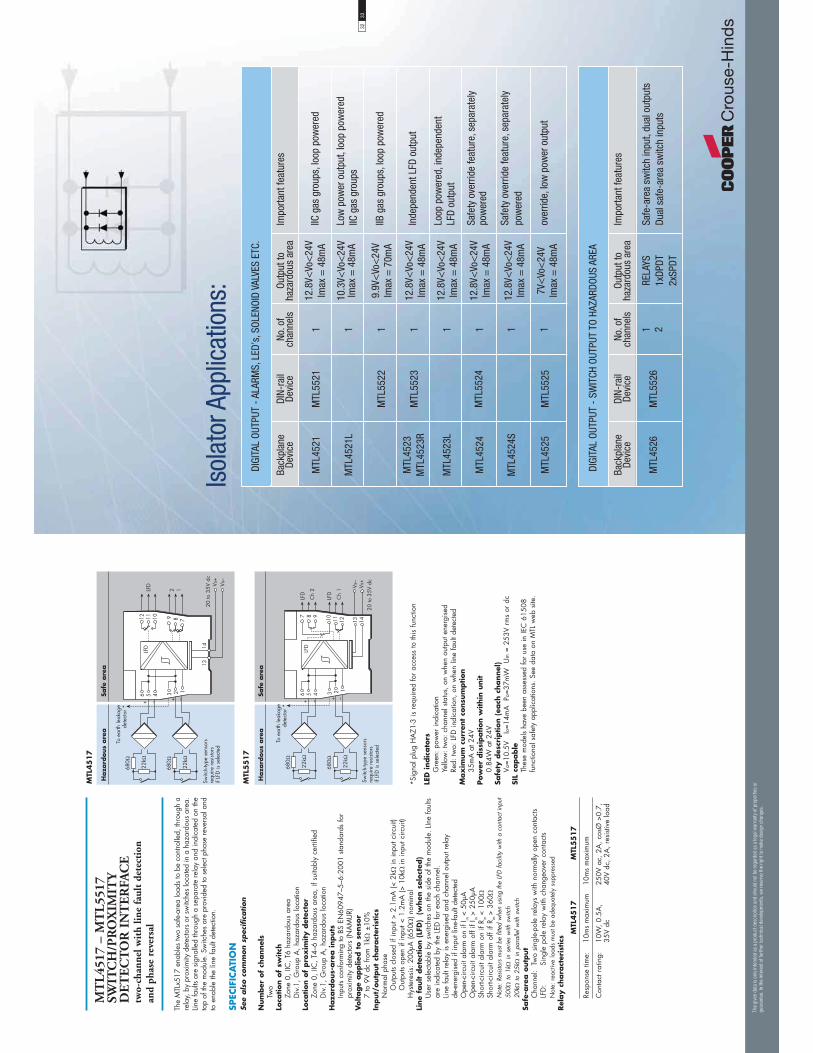
MT
L45
17 –
MT
L55
17
SWIT
CH
/PR
OX
IMIT
Y
DE
TE
CT
OR
IN
TE
RFA
CE
two-
chan
nel w
ith
line
faul
t de
tect
ion
and
phas
e re
vers
al
The
MTL
x517
ena
bles
two
safe
-are
a lo
ads
to b
e co
ntro
lled,
thro
ugh
a re
lay,
by
prox
imity
det
ecto
rs o
r sw
itche
s lo
cate
d in
a h
azar
dous
are
a.
Line
faul
ts ar
e si
gnal
led
thro
ugh
a se
para
te re
lay
and
indi
cate
d on
the
top
of th
e m
odul
e. S
witc
hes
are
prov
ided
to s
elec
t pha
se re
vers
al a
nd
to e
nabl
e th
e lin
e fa
ult d
etec
tion.
SPEC
IFIC
ATI
ON
See
als
o c
om
mon s
pec
ific
ation
Num
ber
of
channel
sTw
oLo
cation o
f sw
itch
Zone
0, I
IC, T
6 ha
zard
ous
area
Div.
1, G
roup
A, h
azar
dous
loca
tion
Loca
tion o
f pro
xim
ity d
etec
tor
Zone
0, I
IC, T
4–6
haza
rdou
s ar
ea, i
f sui
tabl
y ce
rtifie
dD
iv.1,
Gro
up A
, haz
ardo
us lo
catio
nH
aza
rdous-
are
a inputs
Inpu
ts co
nfor
min
g to
BS
EN60
947–
5–6:
2001
sta
ndar
ds fo
r pr
oxim
ity d
etec
tors
(NA
MU
R)V
oltage
applie
d t
o s
enso
r7
to 9
V dc
from
1k
±10
%In
put/
outp
ut
chara
cter
istics
Nor
mal
pha
se
Out
puts
clos
ed if
inpu
t > 2
.1m
A (<
2k
in in
put c
ircui
t)
Out
puts
open
if in
put <
1.2
mA
(> 1
0kin
inpu
t circ
uit)
Hys
tere
sis:
200
μA (6
50) n
omin
alLi
ne
fault d
etec
tion (
LFD
) (
when
sel
ecte
d)
Use
r se
lect
able
by
switc
hes
on th
e si
de o
f the
mod
ule.
LIn
e fa
ults
are
indi
cate
d by
the
LED
for
each
cha
nnel
.Lin
e fa
ult r
elay
is e
nerg
ised
and
cha
nnel
out
put r
elay
de
-ene
rgis
ed if
inpu
t lin
e-fa
ult d
etec
ted
Ope
n-ci
rcui
t ala
rm o
n if
I in <
50μ
AO
pen-
circ
uit a
larm
off
if I in
> 2
50μA
Shor
t-circ
uit a
larm
on
if R in
< 1
00Sh
ort-c
ircui
t ala
rm o
ff if
R in >
360
Not
e: R
esist
ors
mus
t be
fitte
d w
hen
usin
g th
e LF
D fa
cilit
y w
ith a
con
tact
inpu
t50
0 to
1k
in s
erie
s w
ith s
witc
h20
k to
25k
in p
aral
lel w
ith s
witc
hSa
fe-a
rea o
utp
ut
Cha
nnel
: Tw
o si
ngle
-pol
e re
lays
with
nor
mal
ly o
pen
cont
acts
LFD
: Si
ngle
pol
e re
lay
with
cha
ngeo
ver
cont
acts
Not
e: r
eact
ive
load
s m
ust b
e ad
equa
tely
sup
pres
sed
Rel
ay c
hara
cter
istics
MTL
45
17
MTL
55
17
Resp
onse
tim
e:10
ms
max
imum
10m
s m
axim
um
Con
tact
rat
ing:
10W
, 0.5
A,
35V
dc25
0V a
c, 2
A, c
osØ
>0.
7,
40V
dc, 2
A, r
esis
tive
load
*Sig
nal p
lug
HA
Z1-3
is r
equi
red
for
acce
ss to
this
func
tion
LED
indic
ato
rsG
reen
: pow
er in
dica
tion
Yello
w: t
wo:
cha
nnel
sta
tus,
on
whe
n ou
tput
ene
rgis
edRe
d: tw
o: L
FD in
dica
tion,
on
whe
n lin
e fa
ult d
etec
ted
Max
imum
curr
ent
consu
mption
35m
A a
t 24V
Pow
er d
issi
pation w
ithin
unit
0.84
W a
t 24V
Safe
ty d
escr
iption (
each
channel
)Vo
=10.
5V
Io=1
4mA
Po
=37m
W
Um =
253
V rm
s or
dc
SIL
capable
Thes
e m
odel
s ha
ve b
een
asse
ssed
for
use
in IE
C 6
1508
fu
nctio
nal s
afet
y ap
plic
atio
ns. S
ee d
ata
on M
TL w
eb s
ite.
Haza
rdous
are
aSa
fe a
rea
������
��� ����
���
� �
� �
+!���$,�"����%����
��-�������������
���������������
1$�
1$�
���
����
&(�
����
&(�
.�����$�����/�
��������0
& � � � �
' ( )
� �� �� � ��
���
MTL
55
17
MTL
45
17
Haza
rdous
are
aSa
fe a
rea
���
� �
� �
+!���$,�"����%����
��-�������������
���������������
�����
&(�
����
&(�
������
��� ����
�
.�����$�����/�
��������0
& � � � �
���
) ( '�� �� �
� ��
Back
plan
eDe
vice
MTL
4521
MTL
4521
L
MTL
4523
MTL
4523
R
MTL
4523
L
MTL
4524
MTL
4524
S
MTL
4525
DIN-
rail
Devi
ce
MTL
5521
MTL
5522
MTL
5523
MTL
5524
MTL
5525
No. o
f ch
anne
ls
1 1 1 1 1 1 1 1
Impo
rtant
feat
ures
IIC g
as g
roup
s, lo
op p
ower
ed
Low
pow
er o
utpu
t, lo
op p
ower
edIIC
gas
gro
ups
IIB g
as g
roup
s, lo
op p
ower
ed
Inde
pend
ent L
FD o
utpu
t
Loop
pow
ered
, ind
epen
dent
LF
D ou
tput
Safe
ty o
verr
ide
feat
ure,
sep
arat
ely
pow
ered
Safe
ty o
verr
ide
feat
ure,
sep
arat
ely
pow
ered
over
ride,
low
pow
er o
utpu
t
Outp
ut to
haza
rdou
s ar
ea
12.8
V<Vo
<24
VIm
ax =
48m
A
10.3
V<Vo
<24
VIm
ax =
48m
A
9.9V
<Vo
<24
VIm
ax =
70m
A
12.8
V<Vo
<24
VIm
ax =
48m
A
12.8
V<Vo
<24
VIm
ax =
48m
A
12.8
V<Vo
<24
VIm
ax =
48m
A
12.8
V<Vo
<24
VIm
ax =
48m
A
7V<
Vo<
24V
Imax
= 4
8mA
DIGI
TAL
OUTP
UT -
ALA
RMS,
LED
’s, S
OLEN
OID
VALV
ES E
TC.
Back
plan
eDe
vice
MTL
4526
DIN-
rail
Devi
ce
MTL
5526
No. o
f ch
anne
ls
1 2
Impo
rtant
feat
ures
Safe
-are
a sw
itch
inpu
t, du
al o
utpu
tsDu
al s
afe-
area
sw
itch
inpu
ts
Outp
ut to
haza
rdou
s ar
ea
RELA
YS1x
DPDT
2xSP
DT
DIGI
TAL
OUTP
UT -
SW
ITCH
OUT
PUT
TO H
AZAR
DOUS
ARE
A
Isol
ator
App
licat
ions
:
The
giv
en d
ata
is o
nly
inte
nded
as
a pro
duct
des
crip
tion
and
shou
ld n
ot b
e re
gar
ded
as
a le
gal
war
ranty
of pro
per
ties
or
guar
ante
e. In
the
inte
rest
of
furt
her
tec
hnic
al d
evel
opm
ents
, w
e re
serv
e th
e ri
ght
to m
ake
des
ign
chan
ges
.
3233

MT
L45
21/L
– M
TL
5521
SO
LE
NO
ID/
AL
AR
M D
RIV
ER
loop
-pow
ered
, IIC
The
MTL
x521
/L i
s a
loop
-pow
ered
mod
ule
whi
ch e
nabl
es a
dev
ice
loca
ted
in th
e ha
zard
ous
area
to b
e co
ntro
lled
from
the
safe
are
a. T
he
MTL
x521
can
driv
e a
certi
fied
intri
nsic
ally
saf
e lo
w-p
ower
load
, as
w
ell a
s no
n-en
ergy
-stor
ing
sim
ple
appa
ratu
s su
ch a
s an
LED
.
SPEC
IFIC
ATI
ON
See
als
o c
om
mon s
pec
ific
ation
Num
ber
of
channel
sO
neLo
cation o
f lo
ad
Zone
0, I
IC, T
4–-6
haz
ardo
us a
rea
if su
itabl
y ce
rtifie
dD
iv. 1
, Gro
up A
haz
ardo
us lo
catio
n
Min
imum
outp
ut
voltage
E
quiv
ale
nt
outp
ut
circ
uit
(MTL
x5
21)
�������
������� ���
�����
��������
����
��
����
��4�� �%� �
�(�� �5� �
1����%��� ��6�( 3
Min
imum
outp
ut
voltage
E
quiv
ale
nt
outp
ut
circ
uit
(MTL
45
21L)
Input
voltage
20 to
35V
dc
Haza
rdous-
are
a o
utp
ut
(MTL
x5
21)
Min
imum
out
put v
olta
ge:
12.8
V at
48m
AM
axim
um o
utpu
t vol
tage
: 24
V fro
m 1
80C
urre
nt li
mit:
48m
AH
aza
rdous-
are
a o
utp
ut
(MTL
45
21L)
Min
imum
out
put v
olta
ge:
10.3
V at
48m
AM
axim
um o
utpu
t vol
tage
: 24
V fro
m 2
32C
urre
nt li
mit:
48m
AO
utp
ut
ripple
< 0.
5% o
f max
imum
out
put,
peak
to p
eak
Res
ponse
tim
eO
utpu
t with
in 1
0% o
f fin
al v
alue
with
in 1
00m
s
*Sig
nal p
lug
HA
Z1-3
is r
equi
red
for
acce
ss to
this
func
tion
LED
indic
ato
rYe
llow
: out
put s
tatu
s, o
n w
hen
outp
ut a
ctiv
eM
ax
imum
curr
ent
consu
mption
90m
A a
t 24V
Pow
er d
issi
pation w
ithin
unit
1.4W
at 2
4V
Safe
ty d
escr
iption (
MTL
x5
21)
Vo=2
5V
Io=1
47m
A
Po=0
.92W
U
m =
253
V rm
s or
dc
Safe
ty d
escr
iption (
MTL
45
21L)
Vo=
25V
Io
= 10
8mA
Po
= 0.
68W
U
m =
253
V rm
s or
dc
SIL
capable
Thes
e m
odel
s ha
ve b
een
asse
ssed
for
use
in IE
C 6
1508
fu
nctio
nal s
afet
y ap
plic
atio
ns. S
ee d
ata
on M
TL w
eb s
ite.
Haza
rdous
are
aSa
fe a
rea
& � � � �
' ( )
� �� �� � ��
+���%���7���� ��
��$���+��8���
�� ���� � �
� �
.�����$�����/�
��������0
MTL
55
21
MTL
45
21 /
MTL
45
21L
Haza
rdous
are
aSa
fe a
rea
& � � � �
+���%���7���� ��
��$���+��8���
�� ���� � �
� �
.�����$�����/�
��������0
) ( '�� �� �
� ��
3435
MT
L55
22
SOL
EN
OID
/AL
AR
M D
RIV
ER
loop
-pow
ered
, IIB
The
MTL
5522
is
a lo
op-p
ower
ed m
odul
e w
hich
ena
bles
a d
evic
e lo
cate
d in
the
haz
ardo
us a
rea
to b
e co
ntro
lled
from
the
saf
e ar
ea.
The
MTL
5522
can
driv
e a
certi
fied
intri
nsic
ally
saf
e lo
w-p
ower
load
, as
wel
l as
non-
ener
gy-st
orin
g si
mpl
e ap
para
tus
such
as
an L
ED.
The
unit'
s in
put/
outp
ut is
olat
ion
allo
ws
the
cont
rol s
witc
h to
be
conn
ecte
d in
to e
ither
sid
e of
the
24V
dc s
uppl
y ci
rcui
t.
SPEC
IFIC
ATI
ON
See
als
o c
om
mon s
pec
ific
ation
Num
ber
of
channel
sO
neLo
cation o
f lo
ad
Zone
0, I
IB, T
4–6
haza
rdou
s ar
ea if
sui
tabl
y ce
rtifie
dD
iv. 1
, Gro
up C
haz
ardo
us lo
catio
nM
inim
um
outp
ut
voltage
E
quiv
ale
nt
outp
ut
circ
uit
�������
������� ���
�����
��������
����
�� ���
��4�� �%� �
��(�� �5� �
1����%��� ��6' 3
Input
voltage
20 to
35V
dc
Haza
rdous-
are
a o
utp
ut
Min
imum
out
put v
olta
ge:
9.9V
at 7
0mA
Max
imum
out
put v
olta
ge:
24V
from
158
Cur
rent
lim
it:
70
mA
Outp
ut
ripple
< 0.
5% o
f max
imum
out
put,
peak
to p
eak
Res
ponse
tim
eO
utpu
t with
in 1
0% o
f fin
al v
alue
with
in 1
00m
s
*Sig
nal p
lug
HA
Z1-3
is r
equi
red
for
acce
ss to
this
func
tion
LED
indic
ato
rYe
llow
: out
put s
tatu
s, o
n w
hen
outp
ut a
ctiv
eM
ax
imum
curr
ent
consu
mption
125m
A (t
yp.)
at 2
4V
Pow
er d
issi
pation w
ithin
unit
1.4W
at 2
4V
Safe
ty d
escr
iption
Vo=2
5V
Io=1
66m
A
Po=1
.04W
U
m =
253
V rm
s or
dc
SIL
capable
Thes
e m
odel
s ha
ve b
een
asse
ssed
for
use
in IE
C 6
1508
fu
nctio
nal s
afet
y ap
plic
atio
ns. S
ee d
ata
on M
TL w
eb s
ite.
Haza
rdous
are
aSa
fe a
rea
& � � � �
' ( )
� �� �� � ��
+���%���7���� ��
��$���+��8���
�� ���� � �
� �
.�����$�����/�
��������0
MTL
55
22
The
giv
en d
ata
is o
nly
inte
nded
as
a pro
duct
des
crip
tion
and
shou
ld n
ot b
e re
gar
ded
as
a le
gal
war
ranty
of pro
per
ties
or
guar
ante
e. In
the
inte
rest
of
furt
her
tec
hnic
al d
evel
opm
ents
, w
e re
serv
e th
e ri
ght
to m
ake
des
ign
chan
ges
.
�������
������� ���
�����
��������
����
��
����
��4�� �%� �
� ��� �5� �
1����%��� ��6�( 3

With
the
MTL
x523
int
erfa
ce,
an o
n/of
f de
vice
in
a ha
zard
ous
area
ca
n be
con
trolle
d by
a v
olt-f
ree
cont
act o
r log
ic s
igna
l in
the
safe
are
a.
It is
sui
tabl
e fo
r dr
ivin
g lo
ads
such
as
sole
noid
s. L
ine
faul
t det
ectio
n (L
FD),
whi
ch o
pera
tes
irres
pect
ive
of t
he o
utpu
t sta
te,
is s
igna
lled
by a
saf
e-ar
ea s
olid
-stat
e sw
itch
whi
ch d
e-en
ergi
ses
MTL
x523
, or
en
ergi
ses
MTL
4523
R, i
f a
field
line
is
open
or
shor
t–ci
rcui
ted.
Ear
th
faul
t de
tect
ion
can
be p
rovi
ded
by c
onne
ctin
g an
MTL
4220
ear
th
leak
age
dete
ctor
to te
rmin
al 3
.
SPEC
IFIC
ATI
ON
See
als
o c
om
mon s
pec
ific
ation
Num
ber
of
channel
sO
neLo
cation o
f lo
ad
Zone
0, I
IC, T
4–6
haza
rdou
s ar
ea if
sui
tabl
y ce
rtifie
dD
iv. 1
, Gro
up A
, haz
ardo
us lo
catio
nM
inim
um
outp
ut
voltage
E
quiv
ale
nt
outp
ut
circ
uit
�������
������� ���
�����
��������
����
��
����
��4�� �%� �
�(�� �5� �
1����%��� ��6�( 3
Haza
rdous-
are
a o
utp
ut
Min
imum
out
put v
olta
ge:
12.8
V at
48m
AM
axim
um o
utpu
t vol
tage
: 24
V fro
m 1
80C
urre
nt li
mit:
48m
AO
utp
ut
ripple
< 0.
5% o
f max
imum
out
put,
peak
to p
eak
Contr
ol in
put
Suita
ble
for s
witc
h co
ntac
ts, a
n op
en c
olle
ctor
tran
sisto
r or l
ogic
driv
e(in
tern
al c
onta
ct w
ettin
g vo
ltage
12V
@ 0
.2m
A c
onta
ct c
lose
d.
Not
sui
tabl
e fo
r vo
ltage
con
trol v
ia s
erie
s di
ode)
Out
put t
urns
on
if in
put s
witc
h cl
osed
, tra
nsis
tor
on o
r
<
1.4V
app
lied
acro
ss c
ontro
l inp
ut 1
1 &
12
Out
put t
urns
off
if in
put s
witc
h op
en, t
rans
isto
r of
f or
> 4.
5V a
pplie
d ac
ross
con
trol i
nput
11
& 1
2Res
ponse
tim
eO
utpu
t with
in 1
0% o
f fin
al v
alue
with
in 1
00m
sLi
ne
fault d
etec
tion (
LFD
)O
pen
or s
hort
circ
uit i
n fie
ld c
ablin
g de
-ene
rgis
es s
olid
sta
te
line-
faul
t sig
nal.
LFD
tran
sisto
r is
sw
itche
d on
, pro
vide
d th
at th
e fie
ld c
ircui
t im
peda
nce
is >
55
and
< 6
k5.
Line
fault s
ignal ch
ara
cter
istics
Max
imum
off-
state
vol
tage
: 35V
Max
imum
off-
state
leak
age
curr
ent:
10μA
Max
imum
on-
state
vol
tage
dro
p: 2
VM
axim
um o
n-sta
te c
urre
nt: 5
0mA
MT
L45
23/R
– M
TL
5523
SO
LE
NO
ID/A
LA
RM
DR
IVE
Rw
ith
line
faul
t de
tect
ion,
IIC
*Sig
nal p
lug
HA
Z1-3
is r
equi
red
for
acce
ss to
this
func
tion
LED
indic
ato
rsG
reen
: pow
er in
dica
tion
Yello
w: o
utpu
t sta
tus,
on
whe
n ou
tput
act
ive
Red:
LFD
indi
catio
n, o
n w
hen
line
faul
t det
ecte
dM
ax
imum
curr
ent
consu
mption
100m
A a
t 24V
dc
Pow
er d
issi
pation w
ithin
unit
1.2W
with
typi
cal s
olen
oid
valv
e, o
utpu
t on
2.0W
wor
st ca
seSa
fety
des
crip
tion
V o=25
V
I o=14
7mA
P o=
919m
W
Um
= 2
53V
rms
or d
cSI
L ca
pable
Thes
e m
odel
s ha
ve b
een
asse
ssed
for
use
in IE
C 6
1508
fu
nctio
nal s
afet
y ap
plic
atio
ns. S
ee d
ata
on M
TL w
eb s
ite.
MTL
55
23
MTL
45
23/M
TL45
23R
3637
With
the
MTL
4523
L in
terfa
ce,
an o
n/of
f dev
ice
in a
haz
ardo
us a
rea
can
be c
ontro
lled
by a
vol
tage
sig
nal i
n th
e sa
fe a
rea.
It i
s su
itabl
e fo
r dr
ivin
g lo
ads
such
as
sole
noid
s. L
ine
faul
t det
ectio
n (L
FD),
whi
ch
oper
ates
whe
n th
e ou
tput
is
ener
gise
d, i
s si
gnal
led
by a
saf
e-ar
ea
solid
-stat
e sw
itch
whi
ch e
nerg
ises
if
a fie
ld l
ine
is o
pen
or s
hort-
circ
uite
d. E
arth
fau
lt de
tect
ion
can
be p
rovi
ded
by c
onne
ctin
g an
M
TL42
20 e
arth
leak
age
dete
ctor
to te
rmin
al 3
.
SPEC
IFIC
ATI
ON
See
als
o c
om
mon s
pec
ific
ation
Num
ber
of
channel
sO
neLo
cation o
f lo
ad
Zone
0, I
IC, T
4–6
haza
rdou
s ar
ea if
sui
tabl
y ce
rtifie
dD
iv. 1
, Gro
up A
, haz
ardo
us lo
catio
nM
inim
um
outp
ut
voltage
Eq
uiv
ale
nt
outp
ut
circ
uit
�������
������� ���
�����
��������
����
��
����
��4�� �%� �
�(�� �5� �
1����%��� ��6�( 3
Input
voltage
20 to
35V
dc
Haza
rdous-
are
a o
utp
ut
Min
imum
out
put v
olta
ge:
12.8
V at
48m
AM
axim
um o
utpu
t vol
tage
: 24
V fro
m 1
80C
urre
nt li
mit:
48m
AO
utp
ut
ripple
< 0.
5% o
f max
imum
out
put,
peak
to p
eak
Res
ponse
tim
eO
utpu
t with
in 1
0% o
f fin
al v
alue
with
in 1
00m
sLi
ne
fault d
etec
tion (
LFD
)O
pen
or s
hort
circ
uit i
n fie
ld c
ablin
g en
ergi
ses
solid
sta
te li
ne
faul
t sig
nal
LFD
tran
sisto
r is
sw
itche
d of
f, pr
ovid
ed th
at th
e fie
ld c
ircui
t im
peda
nce
is >
55
and
< 6
k5.
Line
fault s
ignal ch
ara
cter
istics
Max
imum
off-
state
vol
tage
: 35V
Max
imum
off-
state
leak
age
curr
ent:
10μA
Max
imum
on-
state
vol
tage
dro
p: 2
VM
axim
um o
n-sta
te c
urre
nt: 5
0mA
Not
e: L
FD s
igna
l is
Zene
r-dio
de p
rote
cted
aga
inst
indu
ctiv
e lo
ads
MT
L45
23L
SO
LE
NO
ID/
AL
AR
M D
RIV
ER
loop
-pow
ered
wit
h lin
e fa
ult
dete
ctio
n, I
IC
*Sig
nal p
lug
HA
Z1-3
is r
equi
red
for
acce
ss to
this
func
tion
LED
indic
ato
rsYe
llow
: out
put s
tatu
s, o
n w
hen
outp
ut a
ctiv
eRe
d: L
FD in
dica
tion,
on
whe
n lin
e fa
ult d
etec
ted
Max
imum
curr
ent
consu
mption
100m
A a
t 24V
dc
Pow
er d
issi
pation w
ithin
unit
1.2W
with
typi
cal s
olen
oid
valv
e, o
utpu
t on
Safe
ty d
escr
iption
Vo=2
5V
Io=1
47m
A
Po=9
19m
W
Um =
253
V rm
s or
dc
SIL
capable
Thes
e m
odel
s ha
ve b
een
asse
ssed
for
use
in IE
C 6
1508
fu
nctio
nal s
afet
y ap
plic
atio
ns. S
ee d
ata
on M
TL w
eb s
ite.
MTL
45
23L
Haza
rdous
are
aSa
fe a
rea
& � � � �
+���%���7���� ��
��$���+��8���
� ����
���
���
��� ����
��
.�����$�����/�
��������0
) ( '�� �� �
� ��
The
giv
en d
ata
is o
nly
inte
nded
as
a pro
duct
des
crip
tion
and
shou
ld n
ot b
e re
gar
ded
as
a le
gal
war
ranty
of pro
per
ties
or
guar
ante
e. In
the
inte
rest
of
furt
her
tec
hnic
al d
evel
opm
ents
, w
e re
serv
e th
e ri
ght
to m
ake
des
ign
chan
ges
.
Haza
rdous
are
aSa
fe a
rea
Haza
rdous
are
aSa
fe a
rea
& � � � �
+���%���7���� ��
��$���+��8���
� �
��
���0
09.���� �
�$�����8�����
������
��� ����
1�%����
��
.�����$�����/�
��������0
) ( '�� �� �
� ��
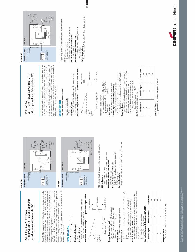
MT
L45
24 –
MT
L55
24
SOL
EN
OID
/AL
AR
M D
RIV
ER
swit
ch o
pera
ted
wit
h ov
erri
de, I
IC
The
MTL
x524
ena
bles
an
on/o
ff de
vice
in
a ha
zard
ous
area
to
be
cont
rolle
d by
a v
olt-f
ree
cont
act
or l
ogic
sig
nal
in t
he s
afe
area
. It
can
driv
e lo
ads
such
as
sole
noid
s, a
larm
s, L
EDs
and
othe
r low
pow
er
devi
ces
that
are
cer
tifie
d as
intri
nsic
ally
saf
e or
are
cla
ssifi
ed a
s no
n-en
ergy
sto
ring
sim
ple
appa
ratu
s.
The
MTL
4524
allo
ws
a se
cond
saf
e-ar
ea s
witc
h or
log
ic s
igna
l to
be
con
nect
ed t
hat
enab
les
the
outp
ut t
o be
dis
able
d to
per
mit,
for
ex
ampl
e, a
saf
ety
syste
m to
ove
rrid
e a
cont
rol s
igna
l.Th
e M
TL55
24 m
ay h
ave
its p
hase
rev
erse
d by
con
nect
ing
a w
ire li
nk
betw
een
pins
8 a
nd 9
.
SPEC
IFIC
ATI
ON
See
als
o c
om
mon s
pec
ific
ation
Num
ber
of
channel
sO
neLo
cation o
f lo
ad
Zone
0, I
IC, T
4–6
haza
rdou
s ar
ea if
sui
tabl
y ce
rtifie
d D
iv.1,
Gro
up A
, haz
ardo
us lo
catio
nM
inim
um
outp
ut
voltage
Eq
uiv
ale
nt
outp
ut
circ
uit
�������
������� ���
�����
��������
����
��
����
��4�� �%� �
�(�� �5� �
1����%��� ��6�( 3
Haza
rdous-
are
a o
utp
ut
Min
imum
out
put v
olta
ge:
12.8
V at
48m
AM
axim
um o
utpu
t vol
tage
: 24
V fro
m 1
80C
urre
nt li
mit:
48m
AO
utp
ut
ripple
< 0.
5% o
f max
imum
out
put,
peak
-to-p
eak
Contr
ol in
put
Suita
ble
for
switc
h co
ntac
ts, a
n op
en c
olle
ctor
tran
sisto
r or
logi
c dr
ive
0 =
inpu
t sw
itch
clos
ed, t
rans
isto
r on
or
<1.4
V ap
plie
d1
= in
put s
witc
h op
en, t
rans
isto
r of
f or
>4.5
V ap
plie
d O
verr
ide
input
on M
TL45
24
An
open
col
lect
or tr
ansi
stor
or a
sw
itch
conn
ecte
d ac
ross
the
term
inal
s ca
n be
use
d to
turn
the
outp
ut o
ff w
hate
ver
the
state
of
the
cont
rol i
nput
0
= tra
nsis
tor
on o
r sw
itch
clos
ed1
= tra
nsis
tor
off o
r sw
itch
open
Contr
ol and o
verr
ide
inputs
on M
TL45
24
Contr
ol in
put
Ove
rrid
e in
put
Outp
ut
state
00
off
01
on
10
off
11
off
Res
ponse
tim
eO
utpu
t with
in 1
0% o
f fin
al v
alue
with
in 1
00m
s
*Sig
nal p
lug
HA
Z1-3
is r
equi
red
for
acce
ss to
this
func
tion
LED
indic
ato
rsG
reen
: pow
er in
dica
tion
Yello
w: o
utpu
t sta
tus,
on
whe
n ou
tput
act
ive
Max
imum
curr
ent
consu
mption
100m
A a
t 24V
dc
Pow
er d
issi
pation w
ithin
unit
1.3W
with
typi
cal s
olen
oid
valv
e, o
utpu
t on
1.9W
wor
st ca
seSa
fety
des
crip
tion
Vo=2
5V
Io=1
47m
A
Po=9
19m
W
Um
= 2
53V
rms
or d
c
MTL
45
24
Haza
rdous
are
aSa
fe a
rea
& � � � �
+���%���7���� ��
��$���+��8���
� �
��
������
��� ����
1�%����
� �
*8������
.�����$�����/�
��������0
) ( '�� �� �
� ��
MTL
55
24
Haza
rdous
are
aSa
fe a
rea
& � � � �
' ( )
� �� �� � ��
+���%���7���� ��
��$���+��8���
� �
������
��� ����
��
1�%����
:
:�����%�����8�����$���
.�����$�����/�
��������0
3839
MT
L45
24S
SO
LE
NO
ID/A
LA
RM
DR
IVE
Rsw
itch
ope
rate
d w
ith
24V
ove
rrid
e, I
IC
The
MTL
4524
S en
able
s an
on/
off d
evic
e in
a h
azar
dous
are
a to
be
cont
rolle
d by
a v
olt-f
ree
cont
act o
r a
float
ing
logi
c si
gnal
in th
e sa
fe
area
. It c
an d
rive
load
s su
ch a
s so
leno
ids,
ala
rms,
LED
s an
d ot
her l
ow
pow
er d
evic
es th
at a
re c
ertif
ied
as in
trins
ical
ly s
afe
or a
re c
lass
ified
as
non
-ene
rgy
storin
g si
mpl
e ap
para
tus.
By
conn
ectin
g a
seco
nd s
afe-
area
vol
tage
, th
e ou
tput
can
be
disa
bled
to
perm
it, f
or e
xam
ple,
a
safe
ty s
yste
m to
ove
rrid
e a
cont
rol s
igna
l.
SPEC
IFIC
ATI
ON
See
als
o c
om
mon s
pec
ific
ation
Num
ber
of
channel
sO
neLo
cation o
f lo
ad
Zone
0, I
IC, T
4–6
haza
rdou
s ar
ea if
sui
tabl
y ce
rtifie
d D
iv.1,
Gro
up A
, haz
ardo
us lo
catio
nM
inim
um
outp
ut
voltage
Eq
uiv
ale
nt
outp
ut
circ
uit
�������
������� ���
�����
��������
����
��
����
��4�� �%� �
�(�� �5� �
1����%��� ��6�( 3
Haza
rdous-
are
a o
utp
ut
Min
imum
out
put v
olta
ge:
12.8
V at
48m
AM
axim
um o
utpu
t vol
tage
: 24
V fro
m 1
80C
urre
nt li
mit:
48m
AO
utp
ut
ripple
< 0.
5% o
f max
imum
out
put,
peak
-to-p
eak
Contr
ol in
put
(must
be
fully
-flo
ating)
Suita
ble
for s
witc
h co
ntac
ts or
an
opto
-isol
ator
0 =
in
put s
witc
h cl
osed
, tra
nsis
tor
on o
r <
1.4V
app
lied
1 =
in
put s
witc
h op
en, t
rans
isto
r of
f or
> 4.
5V a
pplie
dO
verr
ide
input
A
24V
logi
c si
gnal
app
lied
acro
ss th
e te
rmin
als
allo
ws
the
sole
noid
/ala
rm to
be
oper
ated
by
the
cont
rol i
nput
. If i
t is
disc
onne
cted
, the
sol
enoi
d/al
arm
is o
ff.0
= <
2.0V
app
lied
acro
ss te
rmin
als
8 &
91
= >
9.0V
app
lied
acro
ss te
rmin
als
8 &
9
(nom
inal
sw
itchi
ng p
oint
4.5
V)Contr
ol and o
verr
ide
inputs
Contr
ol in
put
Ove
rrid
e in
put
Outp
ut
state
00
off
01
on
10
off
11
off
Res
ponse
tim
eO
utpu
t with
in 1
0% o
f fin
al v
alue
with
in 1
00m
s
*Sig
nal p
lug
HA
Z1-3
is r
equi
red
for
acce
ss to
this
func
tion
LED
indic
ato
rsG
reen
: pow
er in
dica
tion
Yello
w: o
utpu
t sta
tus,
on
whe
n ou
tput
act
ive
Max
imum
curr
ent
consu
mption
100m
A a
t 24V
dc
Pow
er d
issi
pation w
ithin
unit
1.3W
with
typi
cal s
olen
oid
valv
e, o
utpu
t on
1.9W
wor
st ca
seSa
fety
des
crip
tion
Vo=2
5V
Io=1
47m
A
Po=9
19m
W
Um
= 2
53V
rms
or d
c
MTL
45
24S
The
giv
en d
ata
is o
nly
inte
nded
as
a pro
duct
des
crip
tion
and
shou
ld n
ot b
e re
gar
ded
as
a le
gal
war
ranty
of pro
per
ties
or
guar
ante
e. In
the
inte
rest
of
furt
her
tec
hnic
al d
evel
opm
ents
, w
e re
serv
e th
e ri
ght
to m
ake
des
ign
chan
ges
.
Haza
rdous
are
aSa
fe a
rea
& � � � �
+���%���7���� ��
��$���+��8���
� �
��
������
��� ����
1�%����
��
*8������
.�����$�����/�
��������0
���
) ( '�� �� �
� ��
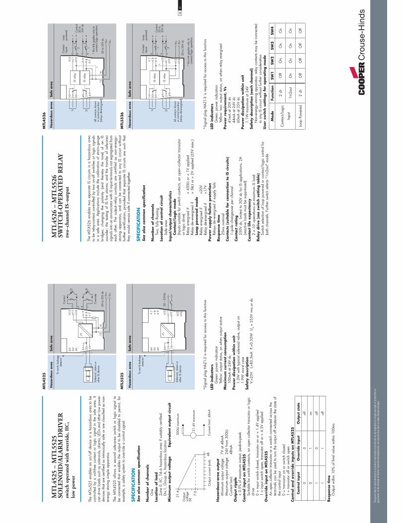
MT
L45
25 –
MT
L55
25
SOL
EN
OID
/AL
AR
M D
RIV
ER
swit
ch o
pera
ted
wit
h ov
erri
de, I
IC,
low
pow
er
The
MTL
x525
ena
bles
an
on/o
ff de
vice
in
a ha
zard
ous
area
to
be
cont
rolle
d by
a v
olt-f
ree
cont
act
or l
ogic
sig
nal
in t
he s
afe
area
. It
can
driv
e lo
ads
such
as
sole
noid
s, a
larm
s, L
EDs
and
othe
r low
pow
er
devi
ces
that
are
cer
tifie
d as
intri
nsic
ally
saf
e or
are
cla
ssifi
ed a
s no
n-en
ergy
sto
ring
sim
ple
appa
ratu
s.
The
MTL
4525
allo
ws
a se
cond
saf
e-ar
ea s
witc
h or
log
ic s
igna
l to
be
con
nect
ed t
hat
enab
les
the
outp
ut t
o be
dis
able
d to
per
mit,
for
ex
ampl
e, a
saf
ety
syste
m to
ove
rrid
e a
cont
rol s
igna
l.
SPEC
IFIC
ATI
ON
See
als
o c
om
mon s
pec
ific
ation
Num
ber
of
channel
sO
neLo
cation o
f lo
ad
Zone
0, I
IC, T
4–6
haza
rdou
s ar
ea if
sui
tabl
y ce
rtifie
d D
iv.1,
Gro
up A
, haz
ardo
us lo
catio
nM
inim
um
outp
ut
voltage
Eq
uiv
ale
nt
outp
ut
circ
uit
��4�� �%� �
� �5� �
1����%��� ��6�( 3
�(
*����������%�; 3<
*�����
8����/�
;�<��4�
'4
Haza
rdous-
are
a o
utp
ut
Min
imum
out
put v
olta
ge:
7V a
t 48m
AM
axim
um o
utpu
t vol
tage
: 24
V fro
m 3
00C
urre
nt li
mit:
48m
AO
utp
ut
ripple
< 0.
5% o
f max
imum
out
put,
peak
-to-p
eak
Contr
ol in
put
on M
TL45
25
Suita
ble
for
switc
h co
ntac
ts, a
n op
en c
olle
ctor
tran
sisto
r or
logi
c dr
ive
0 =
inpu
t sw
itch
clos
ed, t
rans
isto
r on
or
< 1.
4V a
pplie
d1
= in
put s
witc
h op
en, t
rans
isto
r of
f or
> 4.
5V a
pplie
dO
verr
ide
input
on M
TL45
25
An
open
col
lect
or tr
ansi
stor
or a
sw
itch
conn
ecte
d ac
ross
the
term
inal
s ca
n be
use
d to
turn
the
outp
ut o
ff w
hate
ver
the
state
of
the
cont
rol i
nput
0
= tra
nsis
tor
on o
r sw
itch
clos
ed1
= tra
nsis
tor
off o
r sw
itch
open
Contr
ol and o
verr
ide
inputs
on M
TL45
25
Contr
ol in
put
Ove
rrid
e in
put
Outp
ut
state
00
off
01
on
10
off
11
off
Res
ponse
tim
eO
utpu
t with
in 1
0% o
f fin
al v
alue
with
in 1
00m
s
*Sig
nal p
lug
HA
Z1-3
is r
equi
red
for
acce
ss to
this
func
tion
LED
indic
ato
rsG
reen
: pow
er in
dica
tion
Yello
w: o
utpu
t sta
tus,
on
whe
n ou
tput
act
ive
Max
imum
curr
ent
consu
mption
100m
A a
t 24V
dc
Pow
er d
issi
pation w
ithin
unit
1.3W
with
typi
cal s
olen
oid
valv
e, o
utpu
t on
1.9W
wor
st ca
seSa
fety
des
crip
tion
V o=25
V
I o=83
.3m
A
P o=0.
52W
U
m =
253
V rm
s or
dc
MTL
45
25
Haza
rdous
are
aSa
fe a
rea
& � � � �
+���%���7���� ��
��$���+��8���
� �
��
������
��� ����
1�%����
� �
*8������
.�����$�����/�
��������0
) ( '�� �� �
� ��
MTL
55
25
Haza
rdous
are
aSa
fe a
rea
& � � � �
' ( )
� �� �� � ��
+���%���7���� ��
��$���+��8���
�� ���� � �
� �
.�����$�����/�
��������0
4041
MT
L45
26 –
MT
L55
26
SWIT
CH
-OP
ER
ATE
D R
EL
AYtw
o–ch
anne
l IS–
outp
ut
The
MTL
X526
ena
bles
two
sepa
rate
IS c
ircui
ts in
a h
azar
dous
are
a to
be
rela
y-co
ntac
t con
trolle
d by
two
on-o
ff sw
itche
s or
logi
c si
gnal
s in
a s
afe
area
. A
pplic
atio
ns i
nclu
de t
he c
alib
ratio
n of
stra
in–g
auge
br
idge
s;
chan
ging
th
e po
larit
y (a
nd
ther
eby
the
tone
) of
an
IS
so
unde
r; th
e te
sting
of
IS f
ire a
larm
s; a
nd t
he t
rans
fer
of s
afe-
area
si
gnal
s in
to a
n an
nunc
iato
r with
IS in
put t
erm
inal
s no
t seg
rega
ted
from
ea
ch o
ther
. Th
e ou
tput
–rel
ay c
onta
cts
are
certi
fied
as n
on–e
nerg
y–sto
ring
appa
ratu
s, a
nd c
an b
e co
nnec
ted
to a
ny I
S ci
rcui
t w
ithou
t fu
rther
cer
tific
atio
n, p
rovi
ded
that
sep
arat
e IS
circ
uits
are
such
tha
t th
ey w
ould
rem
ain
safe
if c
onne
cted
toge
ther
.
SPEC
IFIC
ATI
ON
See
als
o c
om
mon s
pec
ific
ation
Num
ber
of
channel
sTw
o, fu
lly fl
oatin
gLo
cation o
f co
ntr
ol ci
rcuit
Safe
are
aIn
put/
outp
ut
chara
cter
istics
Conta
ct/L
ogic
mode
(Inpu
ts su
itabl
e fo
r sw
itch
cont
acts,
an
open
–col
lect
or tr
ansi
stor
or lo
gic
driv
e)Re
lay
ener
gise
d if
<
450
or
< 1V
app
lied
Rela
y de
–ene
rgis
ed if
>
5k o
r >
2V a
pplie
d (3
5V m
ax.)
Loop p
ow
ered
mode
Rela
y en
ergi
sed
if
>20V
Rela
y de
-ene
rgis
ed if
<1
7VPow
er s
upply
failu
re p
rote
ctio
nRe
lays
de–
ener
gise
d if
supp
ly fa
ilsRes
ponse
tim
e25
ms
nom
inal
Conta
cts
(suitable
for
connec
tion t
o I
S ci
rcuits)
1–po
le c
hang
eove
r pe
r ch
anne
lConta
ct r
ating
250V
dc,
lim
ited
to 3
0V d
c fo
r IS
app
licat
ions
, 2A
(reac
tive
load
s m
ust b
e su
ppre
ssed
)Conta
ct lif
e ex
pec
tancy
2 x
107 o
pera
tions
at m
axim
um IS
load
Rel
ay d
rive
(se
e sw
itch
set
ting t
able
) Sw
itch
sele
ctio
n of
loop
pow
ered
or
cont
act/
logi
c co
ntro
l for
bo
th c
hann
els.
Fur
ther
sw
itch
sele
cts
"1in
2out
" m
ode
*Sig
nal p
lug
HA
Z1-3
is r
equi
red
for
acce
ss to
this
func
tion
LED
indic
ato
rsG
reen
: pow
er in
dica
tion
Yello
w: t
wo:
out
put s
tatu
s, o
n w
hen
rela
y en
ergi
sed
Pow
er r
equir
emen
t, V
s41
mA
at 2
0V d
c44
mA
at 2
4V d
c60
mA
at 3
5V d
cPow
er d
issi
pation w
ithin
unit
1.1W
max
imum
at 2
4VSa
fety
des
crip
tion (
each
channel
)N
on-e
nerg
y–sto
ring
appa
ratu
s: r
elay
con
tact
s m
ay b
e co
nnec
ted
to a
ny IS
circ
uit w
ithou
t fur
ther
con
side
ratio
nU
ser
switch
set
tings
for
oper
ating m
ode
Mode
Funct
ion
SW1
SW2
SW3
SW4
Con
tact
/Log
ic
Inpu
t
2 ch
Off
On
On
On
1in2
out
On
On
On
On
Loop
Pow
ered
2 ch
Off
Off
Off
Off
MTL
45
26
MTL
55
26
Haza
rdous
are
aSa
fe a
rea
� � � � &
�+����"
�+����"
� �
��
��
3����%������$�!%
�%%�� ���������%
;����"���,�%��/����<
0
0�$����%���������%�"��
��%����=��/����������%
������
��� ����
��
��
1�%����
���
����
����
��!����
1�%����
�%����
) ( '�� �� �
��
� ��
Haza
rdous
are
aSa
fe a
rea
� � � � &
' ( )
� �� �� � ��
�+����"
�+����"
�
������
��� ����
� �
�
� �
1�%����
���
����
� � � �
����
��!����
1�%����
�%����
3����%������$�!%
�%%�� ���������%
;����"���,�%��/����<
0 0�$����%���������%�"��
��%����=��/����������%
� �
The
giv
en d
ata
is o
nly
inte
nded
as
a pro
duct
des
crip
tion
and
shou
ld n
ot b
e re
gar
ded
as
a le
gal
war
ranty
of pro
per
ties
or
guar
ante
e. In
the
inte
rest
of
furt
her
tec
hnic
al d
evel
opm
ents
, w
e re
serv
e th
e ri
ght
to m
ake
des
ign
chan
ges
.

Back
plan
eDe
vice
MTL
4531
MTL
4533
MTL
4532
DIN-
rail
Devi
ce
MTL
5531
MTL
5533
MTL
5532
No. o
f ch
anne
ls
1 2 1
Impo
rtant
feat
ures
dc a
nd a
c vo
ltage
tran
sfer
dc a
nd a
c vo
ltage
tran
sfer
Repe
ats
frequ
ency
and
con
verts
toan
alog
ue v
alue
, plu
s tri
p fu
nctio
n
Inpu
t fro
mha
zard
ous
area
2-w
ire &
3-w
irevi
brat
ion
prob
es
2-w
ire &
3-w
irevi
brat
ion
prob
es
Switc
h, p
roxi
mity
dete
ctor
, cur
rent
puls
e, v
olta
gepu
lse
PULS
E AN
D VI
BRAT
ION
INPU
T -
Isol
ator
App
licat
ions
:
4243
The
MTL
x531
repe
ats
a si
gnal
from
a v
ibra
tion
sens
or in
a h
azar
dous
ar
ea,
prov
idin
g an
out
put f
or a
mon
itorin
g sy
stem
in
the
safe
are
a.
The
inte
rface
is
com
patib
le w
ith 3
-wire
edd
y-cu
rren
t pr
obes
and
ac
cele
rom
eter
s or
2-w
ire c
urre
nt s
enso
rs;
the
sele
ctio
n is
mad
e by
a
switc
h on
the
side
of t
he m
odul
e.
SPEC
IFIC
ATI
ON
See
als
o c
om
mon s
pec
ific
ation
Num
ber
of
channel
sO
neLo
cation o
f si
gnal so
urc
eZo
ne 0
, IIC
, T4–
6 ha
zard
ous
area
if s
uita
bly
certi
fied
Div.
1, G
roup
A h
azar
dous
loca
tion
Haza
rdous-
are
a input
Inpu
t im
peda
nce
(term
inal
s 2
& 3
): 10
kTr
ansd
ucer
sup
ply
volta
ge, 3-w
ire
(term
inal
s 3
& 1
)
*����������%��� 3
*�����
8����/�
����
��
��'�
Transd
uce
r su
pply
curr
ent,
2-w
ire
3.3m
A (n
om.)
for
2-w
ire s
enso
rs, u
ser
sele
ctab
le b
y sw
itch
Signal ra
nge
Min
imum
–20
V, m
axim
um –
0.5V
DC t
ransf
er a
ccura
cy a
t 20°C
<±50
mV
AC t
ransf
er a
ccura
cy a
t 20°C
0Hz
to 1
kHz:
±1%
1kH
z to
10k
Hz:
–5%
to +
1%10
kHz
to 2
0kH
z: –
10%
to +
1%Te
mper
atu
re c
oef
fici
ent
±50p
pm/°
C (1
0 to
65°
C)
±100
ppm
/°C
(–20
to 1
0°C
)V
oltage
bandw
idth
–3
dB a
t 47k
Hz
(typi
cal)
Phase
res
ponse
<14μ
s, e
quiv
alen
t to:
–1°
at 2
00H
z–3
° at
600
Hz
–5°
at 1
kHz
–50°
at 1
0kH
z–1
00°
at 2
0kH
zSa
fe-a
rea o
utp
ut
imped
ance
<2
0
LED
indic
ato
rG
reen
: pow
er in
dica
tion
Supply
voltage
20 to
35V
dc
Max
imum
cur
rent
con
sum
ptio
n (1
0mA
tran
sduc
er lo
ad)
96m
A a
t 24V
Max
imum
pow
er d
issi
pation w
ithin
unit
2WSa
fety
des
crip
tion
Term
inals
3 t
o 1
V o=2
6.6V
Io
=94m
A
Po=0
.66W
U
m =
253
V rm
s or
dc
Term
inals
3 t
o 2
Non
-ene
rgy-
storin
g ap
para
tus
1.5V
, 0.
1A a
nd
25m
W
MT
L45
31 –
MT
L55
31
VIB
RAT
ION
TR
AN
SDU
CE
R
INT
ER
FAC
E
Haza
rdous
are
aSa
fe a
rea
& � � � �
��#�����%
���%������
��#�����%
���%������
������
��� ����
) ( '�� �� �
� ��
9�%����
�8�
�
�
,
!��� �,
!���
� ��
MTL
55
31
MTL
45
31
Haza
rdous
are
aSa
fe a
rea
& � � � �
' ( )
� �� �� � ��
��#�����%
���%������
��#�����%
���%������
������
��� ����
�8�
�
9�%����
�
,
!��� �,
!���
� ��
The
giv
en d
ata
is o
nly
inte
nded
as
a pro
duct
des
crip
tion
and
shou
ld n
ot b
e re
gar
ded
as
a le
gal
war
ranty
of pro
per
ties
or
guar
ante
e. In
the
inte
rest
of
furt
her
tec
hnic
al d
evel
opm
ents
, w
e re
serv
e th
e ri
ght
to m
ake
des
ign
chan
ges
.

MT
L45
32 –
MT
L55
32
PU
LSE
ISO
LAT
OR
puls
e &
4/2
0mA
cur
rent
out
puts
The
MTL
x532
is
olat
es
pulse
s fro
m
a sw
itch,
pr
oxim
ity
dete
ctor
, cu
rren
t pu
lse t
rans
mitt
er o
r vo
ltage
pul
se t
rans
mitt
er l
ocat
ed i
n a
haza
rdou
s ar
ea. I
t is
idea
l for
app
licat
ions
invo
lvin
g hi
gh p
ulse
rat
es
and
fast
resp
onse
tim
es,
by r
epea
ting
the
pulse
s in
to th
e sa
fe a
rea.
A
n an
alog
ue o
utpu
t pr
opor
tiona
l to
fre
quen
cy i
s al
so p
rovi
ded,
to
geth
er w
ith a
rel
ay o
utpu
t, w
hich
may
be
conf
igur
ed to
act
as
an
alar
m. C
onfig
urat
ion
is c
arrie
d ou
t with
a p
erso
nal c
ompu
ter.
SPEC
IFIC
ATI
ON
See
als
o c
om
mon s
pec
ific
ation
Num
ber
of
channel
sO
ne, f
ully
floa
ting
Senso
r ty
pe
Switc
h or
pro
xim
ity d
etec
tor
(NA
MU
R/BS
EN
609
47–5
–6:2
001)
2– o
r 3–
wire
vol
tage
or
pulse
tran
smitt
erLo
cation o
f sw
itch
Zone
0, I
IC, T
6 ha
zard
ous
area
Div.
1, G
roup
A, h
azar
dous
loca
tion
Loca
tion o
f pro
xim
ity d
etec
tor
or
transm
itte
rZo
ne 0
, IIC
, T4–
T6 if
sui
tabl
y ce
rtifie
dD
iv.1,
Gro
up A
, haz
ardo
us lo
catio
nIn
put Sw
itch
input:
Out
put O
N if
sw
itch
is c
lose
dPro
xim
ity d
etec
tor
input:
Exci
tatio
n: 7
.0 to
9.0
V dc
from
1k
nom
inal
Out
put O
N if
inpu
t > 2
.1m
A*
(< 2
k)
Out
put O
FF if
inpu
t < 1
.2m
A*
(> 1
0k)
Switc
hing
hys
tere
sis:
0.2
mA
(650
) nom
inal
*NA
MU
R an
d BS
EN
609
47–5
–6:2
001s
tand
ards
Curr
ent
puls
e in
put:
Tran
smitt
er s
uppl
y: 1
6.5V
dc
at 2
0mA
Shor
t circ
uit c
urre
nt: 2
4mA
Out
put:
Iin >
9.0
mA
= O
N,
Iin
< 7.
0mA
= O
FFSw
itchi
ng h
yste
resi
s: 0
.5m
AV
oltage
puls
e in
put
Inpu
t im
peda
nce:
> 1
0kSw
itchi
ng p
oint
vol
tage
(Vsp):
3, 6
, or
12V
nom
inal
(Use
r se
lect
able
by
switc
hes
on th
e si
de o
f the
mod
ule)
Out
put:
Vin
> V
sp =
ON
,
Vin
< V sp
= O
FFSw
itchi
ng h
yste
resi
s: 1
00m
V +
(0.1
x V
sp) t
ypic
alSa
fe-a
rea p
uls
e outp
ut
Max
imum
off–
state
vol
tage
: 35V
Max
imum
off–
state
leak
age
curr
ent:
10μA
Max
imum
on–
state
res
ista
nce:
25
Max
imum
on–
state
cur
rent
: 50m
AO
utpu
t OFF
if s
uppl
y fa
ilsN
ote:
the
outp
ut is
zen
er d
iode
pro
tect
ed a
gain
st in
duct
ive
load
sSa
fe-a
rea c
urr
ent
outp
ut
Sign
al r
ange
: 4 to
20m
AU
nder
/ove
r ra
nge:
0 to
22m
ALo
ad r
esis
tanc
e:
0 to
450
@20
mA
Out
put r
esis
tanc
e: >
1MRi
pple
: < 5
0A
pea
k-to
-pea
kA
ccur
acy:
bet
ter
than
20
A a
t 20°
CTe
mpe
ratu
re d
rift:
< 1
A/°
CRe
spon
se d
elay
: TBA
ms
Ala
rm o
utp
ut
Rela
y O
N in
ala
rm, 0
.5A
@ 3
5Vdc
max
.
Puls
e w
idth
H
igh:
10μ
s m
inLo
w: 1
0μs
min
Freq
uen
cy r
ange
0 –
50kH
z - p
ulse
out
put m
ode
0 –
10KH
z - f
or a
nalo
gue
outp
utLE
D indic
ato
rsG
reen
: pow
er in
dica
tion
Yello
w: o
n w
hen
outp
ut c
ircui
t is
onRe
d: fl
ashi
ng w
hen
line
faul
t or
erro
rPow
er r
equir
emen
t65
mA
at 2
4V d
c70
mA
at 2
0V d
c55
mA
at 3
5V d
cPow
er d
issi
pation w
ithin
unit
1.35
W m
axim
um a
t 24V
1.75
W m
axim
um a
t 35V
Safe
ty d
escr
iption
(U
m =
25
3V
rm
s or
dc)
Term
inals
2 t
o 1
and 6
to 1
V o=10
.5V
I o=
14m
A
P o=37
mW
Term
inals
4 t
o 3
and 1
V o=
28V
I o=
93m
A
P o=65
1mW
Term
inals
3 t
o 1
Non
-ene
rgy-
storin
g ap
para
tus
1.5V
, 0.
1A a
nd
25m
W; c
an
be c
onne
cted
with
out f
urth
er c
ertif
icat
ion
into
any
IS lo
op w
ith a
n op
en-c
ircui
t vol
tage
<28
VTe
rmin
als
5 t
o 4
and 1
V max
28V,
I max
94m
A, P
max
0.66
WConfi
gura
tor
A p
erso
nal c
ompu
ter
runn
ing
MTL
PC
S45
softw
are
with
a
PCL4
5USB
ser
ial i
nter
face
.
MTL
55
32
MTL
45
32
4445
The
MTL
x533
rep
eats
sign
als
from
vib
ratio
n se
nsor
s in
a h
azar
dous
ar
ea,
prov
idin
g ou
tput
s fo
r a
mon
itorin
g sy
stem
in
the
safe
are
a.
The
inte
rface
is
com
patib
le w
ith 3
-wire
edd
y-cu
rren
t pr
obes
and
ac
cele
rom
eter
s or
2-w
ire c
urre
nt s
enso
rs,
the
sele
ctio
n is
mad
e by
sw
itche
s on
the
side
of t
he m
odul
e.
SPEC
IFIC
ATI
ON
See
als
o c
om
mon s
pec
ific
ation
Num
ber
of
channel
sTw
oLo
cation o
f si
gnal so
urc
eZo
ne 0
, IIC
, T4–
6 ha
zard
ous
area
if s
uita
bly
certi
fied
Div.
1, G
roup
A h
azar
dous
loca
tion
Haza
rdous-
are
a input
Inpu
t im
peda
nce
(term
inal
s 2
& 3
, 5 &
6):
10k
Tran
sduc
er s
uppl
y vo
ltage
, 3-w
ire
(term
inal
s 3
& 1
and
6 &
4)
Transd
uce
r su
pply
curr
ent,
2-w
ire
3.3m
A (n
om.)
for
2-w
ire s
enso
rs, u
ser
sele
ctab
le b
y sw
itch
Signal ra
nge
Min
imum
–20
V, m
axim
um –
0.5V
DC t
ransf
er a
ccura
cy a
t 20°C
<±50
mV
AC t
ransf
er a
ccura
cy a
t 20°C
0Hz
to 1
kHz:
±1%
1kH
z to
10k
Hz:
–5%
to +
1%10
kHz
to 2
0kH
z: –
10%
to +
1%Te
mper
atu
re c
oef
fici
ent
±50p
pm/°
C (1
0 to
65°
C)
±100
ppm
/°C
(–20
to 1
0°C
)V
oltage
bandw
idth
–3
dB a
t 47k
Hz
(typi
cal)
Phase
res
ponse
<14μ
s, e
quiv
alen
t to:
–1°
at 2
00H
z–3
° at
600
Hz
–5°
at 1
kHz
–50°
at 1
0kH
z–1
00°
at 2
0kH
zSa
fe-a
rea o
utp
ut
imped
ance
<2
0
LED
indic
ato
rG
reen
: pow
er in
dica
tion
Supply
voltage
20 to
35V
dc
Max
imum
cur
rent
con
sum
ptio
n (1
0mA
tran
sduc
er lo
ad/c
h)13
0mA
at 2
4VM
ax
imum
pow
er d
issi
pation w
ithin
unit
2.7W
Safe
ty d
escr
iption
Term
inals
3 t
o 1
and 6
to 4
V o=2
6.6V
Io
=94m
A
Po=0
.66W
U
m =
253
V rm
s or
dc
Term
inals
3 t
o 2
and 6
to 5
Non
-ene
rgy-
storin
g ap
para
tus
1.5V
, 0.
1A a
nd
25m
W
MT
L45
33 –
MT
L55
33V
IBR
ATIO
N T
RA
NSD
UC
ER
IN
TE
RFA
CE
two
chan
nel
*����������%��� 3
*�����
8����/�
����
��
��'�
Haza
rdous
are
aSa
fe a
rea
��#�����%
���%������
��#�����%
���%������
��#�����%
���%������
��#�����%
���%������
�
�8�
�
9�%����
�
,
!���
� �
,
!��� �,
!���
� �
�,
!���
9�%����
�8�
�
��
1$�
1$�
1$�
1$�
& � � � �
������
��� ����
) ( '�� �� �
� ��
MTL
55
33
MTL
45
33
Haza
rdous
are
aSa
fe a
rea
��#�����%
���%������
��#�����%
���%������
��#�����%
���%������
��#�����%
���%������
�
������
��� ����
�8�
�
9�%����
�
,
!���
� �
,
!��� �,
!���
� �
�,
!���
9�%����
�8�
�
��
1$�
1$�
1$�
1$�
& � � � �
' ( )
� �� �� � ��
The
giv
en d
ata
is o
nly
inte
nded
as
a pro
duct
des
crip
tion
and
shou
ld n
ot b
e re
gar
ded
as
a le
gal
war
ranty
of pro
per
ties
or
guar
ante
e. In
the
inte
rest
of
furt
her
tec
hnic
al d
evel
opm
ents
, w
e re
serv
e th
e ri
ght
to m
ake
des
ign
chan
ges
.
Haza
rdous
are
aSa
fe a
rea
& � � � �
,!���
�����%�
�����
�=�
3
� �
,!���
8����/�
�����
� � �
�,!���
�����%�
�����
�����/�
�����
1����%�
�����
� �
�%$�#��
����
3���
�=� 3
1�%��/������%
������
� �
��
������
��
�����
������
��� ����
�
�=�
3
� �
�=�
3
� � �) ( '�� �� �
� ��
Haza
rdous
are
aSa
fe a
rea
& � � � �
' ( )
� �� �� � ��������
��� ����
,!���
�����%�
�����
�=�
3
� �
,!���
8����/�
�����
� � �
�,!���
�����%�
�����
�����/�
�����
1����%�
�����
� �
�%$�#��
����
3���
�=� 3
1�%��/������%
������
� �
��
������
��
�����
�
�=�
3
� �
�=�
3
� � �
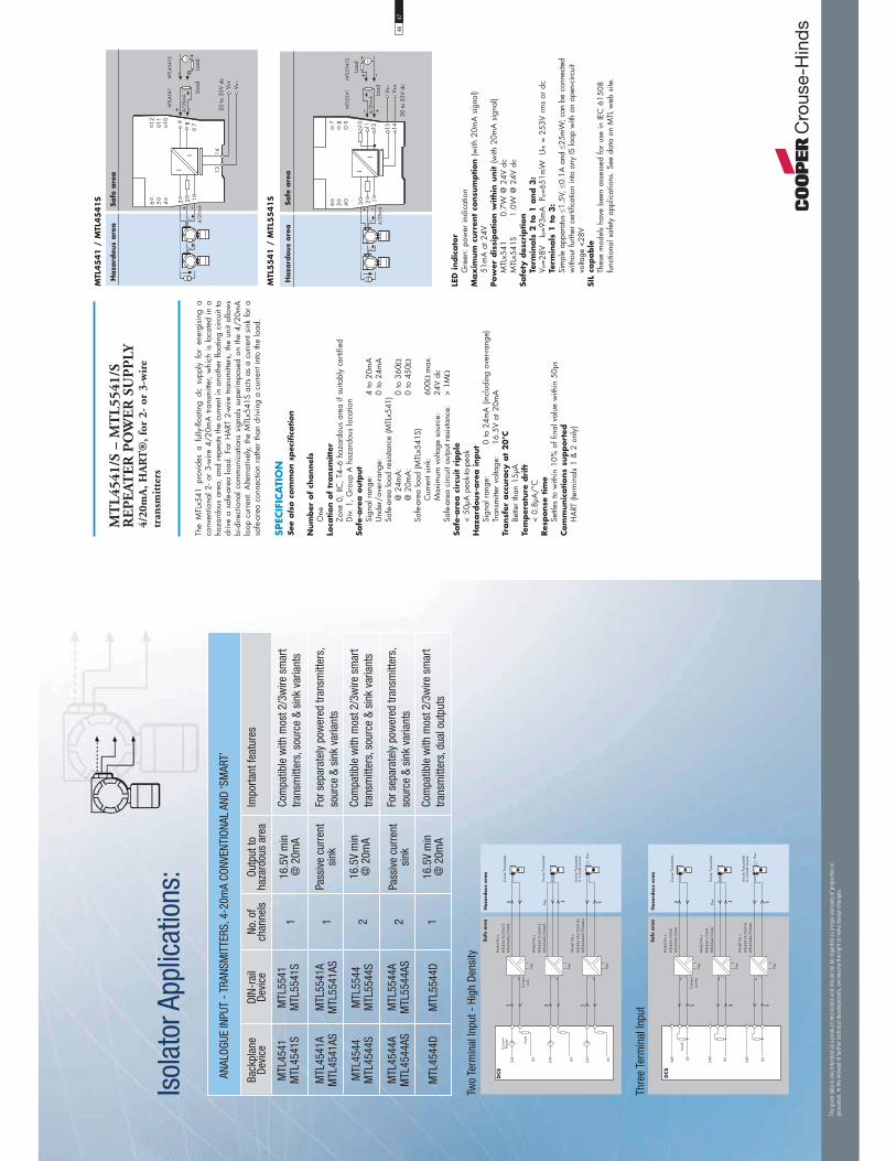
Back
plan
eDe
vice
MTL
4541
MTL
4541
S
MTL
4541
AM
TL45
41AS
MTL
4544
MTL
4544
S
MTL
4544
AM
TL45
44AS
MTL
4544
D
DIN-
rail
Devi
ce
MTL
5541
MTL
5541
S
MTL
5541
AM
TL55
41AS
MTL
5544
MTL
5544
S
MTL
5544
AM
TL55
44AS
MTL
5544
D
No. o
f ch
anne
ls
1 1 2 2 1
Impo
rtant
feat
ures
Com
patib
le w
ith m
ost 2
/3w
ire s
mar
ttra
nsm
itter
s, s
ourc
e &
sink
var
iant
s
For s
epar
atel
y po
wer
ed tr
ansm
itter
s,so
urce
& s
ink
varia
nts
Com
patib
le w
ith m
ost 2
/3w
ire s
mar
ttra
nsm
itter
s, s
ourc
e &
sink
var
iant
s
For s
epar
atel
y po
wer
ed tr
ansm
itter
s,so
urce
& s
ink
varia
nts
Com
patib
le w
ith m
ost 2
/3w
ire s
mar
ttra
nsm
itter
s, d
ual o
utpu
ts
Outp
ut to
haza
rdou
s ar
ea
16.5
V m
in@
20m
A
Pass
ive
curr
ent
sink
16.5
V m
in@
20m
A
Pass
ive
curr
ent
sink
16.5
V m
in@
20m
A
ANAL
OGUE
INPU
T - T
RANS
MIT
TERS
, 4-2
0mA
CONV
ENTI
ONAL
AND
‘SM
ART’
Isol
ator
App
licat
ions
:
Two
Term
inal
Inpu
t - H
igh
Dens
ity
Thre
e Te
rmin
al In
put
4647
MT
L45
41/S
– M
TL
5541
/S
RE
PE
ATE
R P
OW
ER
SU
PP
LY4/
20m
A, H
AR
T®
, for
2-
or 3
-wir
e tr
ansm
itte
rs
The
MTL
x541
pro
vide
s a
fully
-floa
ting
dc s
uppl
y fo
r en
ergi
sing
a
conv
entio
nal 2
- or
3-w
ire 4
/20m
A tr
ansm
itter
, w
hich
is
loca
ted
in a
ha
zard
ous
area
, an
d re
peat
s th
e cu
rren
t in
anot
her
float
ing
circ
uit t
o dr
ive
a sa
fe-a
rea
load
. Fo
r H
ART
2-w
ire tr
ansm
itter
s, th
e un
it al
low
s bi
-dire
ctio
nal c
omm
unic
atio
ns s
igna
ls su
perim
pose
d on
the
4/20
mA
lo
op c
urre
nt.
Alte
rnat
ivel
y, th
e M
TLx5
41S
acts
as a
cur
rent
sin
k fo
r a
safe
-are
a co
nnec
tion
rath
er th
an d
rivin
g a
curr
ent i
nto
the
load
.
SPEC
IFIC
ATI
ON
See
als
o c
om
mon s
pec
ific
ation
Num
ber
of
channel
sO
neLo
cation o
f tr
ansm
itte
rZo
ne 0
, IIC
, T4–
6 ha
zard
ous
area
if s
uita
bly
certi
fied
Div.
1, G
roup
A h
azar
dous
loca
tion
Safe
-are
a o
utp
ut
Sign
al r
ange
:
4
to 2
0mA
Und
er/o
ver-r
ange
:
0 to
24m
ASa
fe-a
rea
load
res
ista
nce
(MTL
x541
)
@ 2
4mA
:
0
to 3
60
@
20m
A:
0 to
450
Safe
-are
a lo
ad (M
TLx5
41S)
Cur
rent
sin
k:
60
0m
ax.
M
axim
um v
olta
ge s
ourc
e:
24V
dcSa
fe-a
rea
circ
uit o
utpu
t res
ista
nce:
>
1MSa
fe-a
rea c
ircu
it r
ipple
< 50
μA p
eak-
to-p
eak
Haza
rdous-
are
a input
Sign
al r
ange
: 0
to 2
4mA
(inc
ludi
ng o
ver-r
ange
) Tr
ansm
itter
vol
tage
: 16
.5V
at 2
0mA
Transf
er a
ccura
cy a
t 20°C
Bette
r th
an 1
5μA
Tem
per
atu
re d
rift
< 0.
8μA
/°C
Res
ponse
tim
eSe
ttles
to w
ithin
10%
of f
inal
val
ue w
ithin
50μ
sCom
munic
ations
support
edH
ART
(ter
min
als
1 &
2 o
nly)
LED
indic
ato
rG
reen
: pow
er in
dica
tion
Max
imum
curr
ent
consu
mption
(with
20m
A s
igna
l)51
mA
at 2
4V
Pow
er d
issi
pation w
ithin
unit (
with
20m
A s
igna
l)M
TLx5
41
0.7W
@ 2
4V d
cM
TLx5
41S
1.0W
@ 2
4V d
cSa
fety
des
crip
tion
Term
inals
2 t
o 1
and 3
:V o
=28V
Io
=93m
A
Po=6
51m
W
Um =
253
V rm
s or
dc
Term
inals
1 t
o 3
:Si
mpl
e ap
para
tus
1.5V
, 0.
1A a
nd
25m
W; c
an b
e co
nnec
ted
with
out f
urth
er c
ertif
icat
ion
into
any
IS lo
op w
ith a
n op
en-c
ircui
t vo
ltage
<28
VSI
L ca
pable
Thes
e m
odel
s ha
ve b
een
asse
ssed
for
use
in IE
C 6
1508
fu
nctio
nal s
afet
y ap
plic
atio
ns. S
ee d
ata
on M
TL w
eb s
ite.
MTL
45
41 /
MTL
45
41S
MTL
55
41 /
MTL
55
41S
Haza
rdous
are
aSa
fe a
rea
& � � � �
' ( )
� �� �� � ��������
��� ����
� ��=� 3
9.�����
9.�����+
� �=� 3 ����
�
����� �
���
�
The
giv
en d
ata
is o
nly
inte
nded
as
a pro
duct
des
crip
tion
and
shou
ld n
ot b
e re
gar
ded
as
a le
gal
war
ranty
of pro
per
ties
or
guar
ante
e. In
the
inte
rest
of
furt
her
tec
hnic
al d
evel
opm
ents
, w
e re
serv
e th
e ri
ght
to m
ake
des
ign
chan
ges
.
Haza
rdous
are
aSa
fe a
rea
& � � � �
� ��=� 3
9.�����
9.�����+
�
������
��� ����
��=� 3
����
������
� �
�
�) ( '�� �� �
� ��

MT
L45
41A
/AS
– M
TL
5541
A/A
S C
UR
RE
NT
RE
PE
ATE
R4/
20m
A p
assi
ve i
nput
fo
r H
AR
T®
tra
nsm
itte
rs
The
MTL
x541
A p
rovi
des
an i
nput
for
sep
arat
ely
pow
ered
4/2
0mA
tra
nsm
itter
s an
d al
so a
llow
s bi
–dire
ctio
nal
trans
mis
sion
of
HA
RT
com
mun
icat
ion
sign
als
supe
rimpo
sed
on t
he 4
/20m
A lo
op c
urre
nt.
Alte
rnat
ivel
y, th
e M
TLx5
41A
S ac
ts as
a c
urre
nt s
ink
for
a sa
fe-a
rea
conn
ectio
n ra
ther
than
driv
ing
a cu
rren
t int
o th
e lo
ad.
SPEC
IFIC
ATI
ON
See
als
o c
om
mon s
pec
ific
ation
Num
ber
of
channel
sO
neLo
cation o
f tr
ansm
itte
rZo
ne 0
, IIC
, T4–
6 ha
zard
ous
area
if s
uita
bly
certi
fied
Div.
1, G
roup
A, h
azar
dous
loca
tion
Haza
rdous
are
a input
Sign
al r
ange
:
4
to 2
0mA
Und
er/o
ver-r
ange
:
1.0
to 2
1.5m
AIn
put
imped
ance
for
HA
RT
signals
at te
rmin
als
1, 2
: > 2
30M
ax
imum
input
volt d
rop
at te
rmin
als
1, 2
: < 6
.6V
i.e. a
tran
smitt
er lo
ad o
f 330
at 2
0mA
Safe
-are
a o
utp
ut
Sign
al r
ange
:
4
to 2
0mA
Und
er/o
ver-r
ange
:
1.0
to 2
1.5m
ASa
fe-a
rea
load
res
ista
nce
(MTL
x541
A)
C
onve
ntio
nal t
rans
mitt
ers:
0
to 3
60
Smar
t tra
nsm
itter
s:
25
0 ±
10%
Safe
-are
a lo
ad (M
TLx5
41A
S)
C
urre
nt s
ink:
600
max
.
Max
imum
vol
tage
sou
rce:
24
V D
CSa
fe-a
rea
circ
uit o
utpu
t res
ista
nce:
>
1MSa
fe–a
rea c
ircu
it r
ipple
< 50
μA p
eak-
to-p
eak
up to
80k
Hz
Transf
er a
ccura
cy a
t 20°C
Bette
r th
an 2
0μA
Tem
per
atu
re d
rift
< 1μ
A/°
CRes
ponse
tim
eSe
ttles
with
in 2
00μA
of f
inal
val
ue a
fter
20m
sCom
munic
ations
support
edH
ART
LED
indic
ato
rG
reen
: pow
er in
dica
tion
Pow
er r
equir
emen
t (w
ith 2
0mA
sig
nal)
50m
A a
t 20V
45m
A a
t 24V
35m
A a
t 35V
Pow
er d
issi
pation w
ithin
unit (
with
20m
A s
igna
ls)M
TLx5
41A
0.
8W @
24V
dc
MTL
x541
AS
1.1W
@ 2
4V d
cSa
fety
des
crip
tion
Term
inals
1 t
o 2
:U
m =
253
V rm
s or
dc.
8.6V
(dio
de).
This
vol
tage
mus
t be
cons
ider
ed w
hen
calc
ulat
ing
the
load
cap
acita
nce.
Non
-ene
rgy-
storin
g ap
para
tus
1.5V
, 0.
1A a
nd
25m
W; c
an
be c
onne
cted
with
out f
urth
er c
ertif
icat
ion
into
any
IS lo
op w
ith a
n op
en-c
ircui
t vol
tage
<28
V
MTL
45
41A
/ M
TL45
41A
S
Haza
rdous
are
aSa
fe a
rea
��=� 3
����
�
��
9.�����3
9.�����3+
������
� �
������
��� ����
�=� 3
& � � � �
�
�
) ( '�� �� �
� ��
MTL
55
41A
/ M
TL5
541A
S
Haza
rdous
are
aSa
fe a
rea
������
��� ����
� �=� 3 ����
�9.�����3
9.�����3+
����� �
��
���=� 3
& � � � �
' ( )
� �� �� � ��
�
�
4849
The
MTL
x544
pr
ovid
es
fully
-floa
ting
dc
supp
lies
for
ener
gisi
ng
two
conv
entio
nal
2-w
ire o
r 3-
wire
4/2
0mA
or
HA
RT t
rans
mitt
ers
loca
ted
in
a ha
zard
ous
area
, an
d re
peat
s th
e cu
rren
t in
ot
her
circ
uits
to d
rive
two
safe
-are
a lo
ads.
For
sm
art
trans
mitt
ers,
the
uni
t al
low
s bi
-dire
ctio
nal
trans
mis
sion
of
digi
tal
com
mun
icat
ion
sign
als
supe
rimpo
sed
on
the
4/20
mA
lo
op
curr
ent.
Alte
rnat
ivel
y,
the
MTL
x544
S ac
ts as
a c
urre
nt s
ink
for
a sa
fe-a
rea
conn
ectio
n ra
ther
th
an d
rivin
g a
curr
ent i
nto
the
load
.
SPEC
IFIC
ATI
ON
See
als
o c
om
mon s
pec
ific
ation
Num
ber
of
channel
sTw
oLo
cation o
f tr
ansm
itte
rZo
ne 0
, IIC
, T4–
6 ha
zard
ous
area
if s
uita
bly
certi
fied
Div.
1, G
roup
A h
azar
dous
loca
tion
Safe
-are
a o
utp
ut
Sign
al r
ange
:
4
to 2
0mA
Und
er/o
ver-r
ange
:
0 to
24m
ASa
fe-a
rea
load
res
ista
nce
(MTL
x 54
4)
@ 2
4mA
:
0
to 3
60
@
20m
A:
0 to
450
Safe
-are
a lo
ad (M
TLx5
44S)
Cur
rent
sin
k:
60
0m
ax.
M
axim
um v
olta
ge s
ourc
e:
24V
dcSa
fe-a
rea
circ
uit o
utpu
t res
ista
nce:
>
1MSa
fe-a
rea c
ircu
it r
ipple
< 50
μA p
eak-
to-p
eak
Haza
rdous-
are
a input
Sign
al r
ange
: 0
to 2
4mA
(inc
ludi
ng o
ver-r
ange
) Tr
ansm
itter
vol
tage
: 16
.5V
at 2
0mA
Transf
er a
ccura
cy a
t 20°C
Bette
r th
an 1
5μA
Tem
per
atu
re d
rift
< 0.
8μA
/°C
Res
ponse
tim
eSe
ttles
to w
ithin
10%
of f
inal
val
ue w
ithin
50μ
sCom
munic
ations
support
edH
ART
(ter
min
als
1 &
2 a
nd 4
& 5
onl
y)
Haza
rdous
are
aSa
fe a
rea
������
��� ����
� �=� 3
����
�� �=� 3
����
�
1$�
1$�
9.�����
9.�����+
� �� ��=� 3
�=� 3
����� �
����� �
& � � � �
' ( )
� �� �� � ��
�
�
�
�
MTL
45
44 /
MTL
45
44S
Haza
rdous
are
aSa
fe a
rea
+ –4/20
mA
Load
Ch
2
Ch
1
MTL
4544
MTL
4544
S
+ –+ –4/
20m
A
4/20
mA
Load
+–
Vs–
Vs+
20 to
35V
dc
Ch
2
Ch
1
+ –4/20
mA
Load
Load
+–I
I
I
I
6 5 4 3 2 1
9 8 712 11 10
1314
MTL
55
44 /
MTL
55
44S
LED
indic
ato
rG
reen
: pow
er in
dica
tion
Max
imum
curr
ent
consu
mption
(with
20m
A s
igna
ls)96
mA
at 2
4V d
cPow
er d
issi
pation w
ithin
unit (
with
20m
A s
igna
ls)M
TLx5
44
1.4W
@ 2
4V d
c M
TLx5
44S
1.9W
@ 2
4V d
cSa
fety
des
crip
tion (
each
channel
)Te
rmin
als
2 t
o 1
and 3
, and 5
to 4
and 6
:V o=
28V
I o=
93m
A
P o=65
1mW
U
m =
253
V rm
s or
dc
Term
inals
1 t
o 3
and 4
to 6
:Si
mpl
e ap
para
tus
1.5V
, 0.
1A a
nd
25m
W; c
an b
e co
nnec
ted
with
out f
urth
er c
ertif
icat
ion
into
any
IS lo
op w
ith a
n op
en-c
ircui
t vo
ltage
<28
V SI
L ca
pable
Thes
e m
odel
s ha
ve b
een
asse
ssed
for
use
in IE
C 6
1508
fu
nctio
nal s
afet
y ap
plic
atio
ns. S
ee d
ata
on M
TL w
eb s
ite.
MT
L45
44/S
– M
TL
5544
/SR
EP
EAT
ER
PO
WE
R S
UP
PLY
two
chan
nel,
4/20
mA
, HA
RT
®,
for
2- o
r 3-
wir
e tr
ansm
itte
rs
The
giv
en d
ata
is o
nly
inte
nded
as
a pro
duct
des
crip
tion
and
shou
ld n
ot b
e re
gar
ded
as
a le
gal
war
ranty
of pro
per
ties
or
guar
ante
e. In
the
inte
rest
of
furt
her
tec
hnic
al d
evel
opm
ents
, w
e re
serv
e th
e ri
ght
to m
ake
des
ign
chan
ges
.

MT
L45
44A
/AS
– M
TL
5544
A/A
S C
UR
RE
NT
RE
PE
ATE
R
4/20
mA
pas
sive
inp
ut f
or H
AR
T®
tra
nsm
itte
rs
The
MTL
x544
A p
rovi
des
an i
nput
for
sep
arat
ely
pow
ered
4/2
0mA
tra
nsm
itter
s an
d al
so a
llow
s bi
–dire
ctio
nal
trans
mis
sion
of
HA
RT
com
mun
icat
ion
sign
als
supe
rimpo
sed
on t
he 4
/20m
A lo
op c
urre
nt,
so t
hat
the
trans
mitt
er c
an b
e in
terr
ogat
ed e
ither
fro
m t
he o
pera
tor
statio
n or
by
a ha
nd-h
eld
com
mun
icat
or (
HH
C).
Alte
rnat
ivel
y, t
he
MTL
x544
AS
acts
as a
cur
rent
sin
k fo
r a
safe
-are
a co
nnec
tion
rath
er
than
driv
ing
a cu
rren
t int
o th
e lo
ad.
SPEC
IFIC
ATI
ON
See
als
o c
om
mon s
pec
ific
ation
Num
ber
of
channel
sTw
oLo
cation o
f tr
ansm
itte
rZo
ne 0
, IIC
, T4–
6 ha
zard
ous
area
if s
uita
bly
certi
fied
Div.
1, G
roup
A, h
azar
dous
loc
atio
nH
aza
rdous
are
a input
Sign
al r
ange
:
4
to 2
0mA
Und
er/o
ver-r
ange
:
1.0
to 2
1.5m
AIn
put
imped
ance
for
HA
RT
signals
at te
rmin
als
1, 2
and
4, 5
: >
230
Max
imum
input
volt d
rop
at te
rmin
als
1, 2
and
4, 5
: <
6.6V
i.e. a
tran
smitt
er lo
ad o
f 330
at 2
0mA
Safe
-are
a o
utp
ut
Sign
al r
ange
:
4
to 2
0mA
Und
er/o
ver-r
ange
:
1.0
to 2
1.5m
ASa
fe-a
rea
load
res
ista
nce
(MTL
5544
A)
C
onve
ntio
nal t
rans
mitt
ers:
0
to 3
60
Smar
t tra
nsm
itter
s:
25
0 ±
10%
Safe
-are
a lo
ad (M
TL55
44A
S)
C
urre
nt s
ink:
600
max
.
Max
imum
vol
tage
sou
rce:
24
V D
CSa
fe-a
rea
circ
uit o
utpu
t res
ista
nce:
>
1MSa
fe–a
rea c
ircu
it r
ipple
< 50
μA p
eak-
to-p
eak
up to
80k
Hz
Transf
er a
ccura
cy a
t 20°C
Bette
r th
an 2
0μA
Tem
per
atu
re d
rift
< 1μ
A/°
CRes
ponse
tim
eSe
ttles
with
in 2
00μA
of f
inal
val
ue a
fter
20m
sCom
munic
ations
support
edH
ART
LED
indic
ato
rG
reen
: pow
er in
dica
tion
Pow
er r
equir
emen
t (w
ith 2
0mA
sig
nal)
70m
A a
t 24V
85m
A a
t 20V
50m
A a
t 35V
Pow
er d
issi
pation w
ithin
unit (
with
20m
A s
igna
ls)M
TLx5
44A
1.
5W @
24V
dc
MTL
x544
AS
2.0W
@ 2
4V d
cSa
fety
des
crip
tion
Term
inals
1 t
o 2
and 4
to 5
:U
m =
253
V rm
s or
dc.
8.6V
(dio
de).
This
vol
tage
mus
t be
cons
ider
ed w
hen
calc
ulat
ing
the
load
cap
acita
nce.
Non
-ene
rgy-
storin
g ap
para
tus
1.5V
, 0.
1A a
nd
25m
W; c
an
be c
onne
cted
with
out f
urth
er c
ertif
icat
ion
into
any
IS lo
op w
ith a
n op
en-c
ircui
t vol
tage
< 2
8V
Haza
rdous
are
aSa
fe a
rea
������
��� ����
� � � �
1$�
1$�
�� �=� 3
1$�
� �
����
����
�� �=� 3
1$�
� �
����
����
�=� 3
�=� 3
& � � � �
' ( )
� �� �� � ��
�
�
�
�
9.�����3
9.�����3+
MTL
45
44A
/AS
Haza
rdous
are
aSa
fe a
rea
� ��=� 3
����
1$�
1$�
9.�����39.�����3+
������
������
��� ����
1$�
1$�
� ��=� 3
����
������
���=� 3
�=� 3
�
�
�
�
& � � � �
) ( '�� �� �
� ��
MTL
55
44A
/AS
5051
The
MTL
x544
D p
rovi
des
a fu
lly-fl
oatin
g dc
sup
ply
for
ener
gisi
ng a
co
nven
tiona
l 2- o
r 3-w
ire 4
/20m
A tr
ansm
itter
loca
ted
in a
haz
ardo
us
area
, an
d re
peat
s th
e cu
rren
t in
othe
r ci
rcui
ts to
driv
e tw
o sa
fe-a
rea
load
s. F
or H
ART
2-w
ire t
rans
mitt
ers,
the
uni
t al
low
s bi
-dire
ctio
nal
trans
mis
sion
of
digi
tal
com
mun
icat
ion
sign
als
supe
rimpo
sed
on t
he
4/20
mA
loop
cur
rent
.
SPEC
IFIC
ATI
ON
See
als
o c
om
mon s
pec
ific
ation
Num
ber
of
channel
sO
neLo
cation o
f tr
ansm
itte
rZo
ne 0
, IIC
, T4–
6 ha
zard
ous
area
if s
uita
bly
certi
fied
Div.
1, G
roup
A h
azar
dous
loca
tion
Safe
-are
a o
utp
ut
Sign
al r
ange
:
4
to 2
0mA
Und
er/o
ver-r
ange
:
0 to
24m
ASa
fe-a
rea
load
res
ista
nce
@
24m
A:
0 to
360
@ 2
0mA
:
0
to 4
50Sa
fe-a
rea
circ
uit o
utpu
t res
ista
nce:
>
1MSa
fe-a
rea c
ircu
it r
ipple
< 50
μA p
eak-
to-p
eak
Haza
rdous-
are
a input
Sign
al r
ange
: 0
to 2
4mA
(inc
ludi
ng o
ver-r
ange
) Tr
ansm
itter
vol
tage
: 16
.5V
at 2
0mA
Transf
er a
ccura
cy a
t 20°C
Bette
r th
an 1
5μA
Tem
per
atu
re d
rift
< 0.
8μA
/°C
Res
ponse
tim
eSe
ttles
to w
ithin
10%
of f
inal
val
ue w
ithin
50μ
sCom
munic
ations
support
edH
ART
(ter
min
als
1 &
2, o
utpu
t Ch
1 on
ly)
MT
L45
44D
– M
TL
5544
D
RE
PE
ATE
R P
OW
ER
SU
PP
LYsi
ngle
cha
nnel
, 4/2
0mA
, HA
RT
®
for
2- o
r 3-
wir
e tr
ansm
itte
rs, t
wo
outp
uts
Haza
rdous
are
aSa
fe a
rea
������
��� ����
1$�
1$�
� �=� 3 ����
� ��=� 3 ����
�
� ��=� 3
& � � � �
' ( )
� �� �� � ��
�
��
MTL
45
44D
Haza
rdous
are
aSa
fe a
rea
� ��=� 3
����
1$�
1$� ������
��� ����
� ��=� 3
����
� ��=� 3
�
�
�
& � � � �
) ( '�� �� �
� ��
MTL
55
44D
LED
indic
ato
rG
reen
: pow
er in
dica
tion
Max
imum
curr
ent
consu
mption
(with
20m
A s
igna
ls)96
mA
at 2
4V d
cPow
er d
issi
pation w
ithin
unit (
with
20m
A s
igna
ls)1.
4W @
24V
dc
Safe
ty d
escr
iption
Term
inals
2 t
o 1
and 3
:V o
=28V
Io
=93m
A
Po=6
51m
W
Um =
253
V rm
s or
dc
Term
inals
1 t
o 3
:Si
mpl
e ap
para
tus
1.5V
, 0.
1A a
nd
25m
W; c
an b
e co
nnec
ted
with
out f
urth
er c
ertif
icat
ion
into
any
IS lo
op w
ith a
n op
en-c
ircui
t vo
ltage
<28
VSI
L ca
pable
Thes
e m
odel
s ha
ve b
een
asse
ssed
for
use
in IE
C 6
1508
fu
nctio
nal s
afet
y ap
plic
atio
ns. S
ee d
ata
on M
TL w
eb s
ite.
The
giv
en d
ata
is o
nly
inte
nded
as
a pro
duct
des
crip
tion
and
shou
ld n
ot b
e re
gar
ded
as
a le
gal
war
ranty
of pro
per
ties
or
guar
ante
e. In
the
inte
rest
of
furt
her
tec
hnic
al d
evel
opm
ents
, w
e re
serv
e th
e ri
ght
to m
ake
des
ign
chan
ges
.
The
giv
en d
ata
is o
nly
inte
nded
as
a pro
duct
des
crip
tion
and
shou
ld n
ot b
e re
gar
ded
as
a le
gal
war
ranty
of pro
per
ties
or
guar
ante
e. In
the
inte
rest
of
furt
her
tec
hnic
al d
evel
opm
ents
, w
e re
serv
e th
e ri
ght
to m
ake
des
ign
chan
ges
.

Back
plan
eDe
vice
MTL
4546
MTL
4546
CM
TL45
46Y
MTL
4549
MTL
4549
CM
TL45
49Y
DIN-
rail
Devi
ce
MTL
5546
MTL
5546
CM
TL55
46Y
MTL
5549
MTL
5549
CM
TL55
49Y
No. o
f ch
anne
ls
1 1 2 2
Impo
rtant
feat
ures
Suita
ble
for H
ART
valv
e po
sitio
ners
,LF
D
Suita
ble
for H
ART
valv
e po
sitio
ners
,op
en c
ct L
FD
Suita
ble
for H
ART
valv
e po
sitio
ners
,LF
D
Suita
ble
for H
ART
valv
e po
sitio
ners
,op
en c
ct L
FD
Outp
ut to
haza
rdou
s ar
ea
1mA
<lo
<24
mA
Vmax
= 1
6V
1mA
<lo
<24
mA
Vmax
= 1
6V
1mA
<lo
<24
mA
Vmax
= 1
6V
1mA
<lo
<24
mA
Vmax
= 1
6V
ANAL
OGUE
OUT
PUT
- CO
NTRO
LLER
OUT
PUTS
, I/P
CON
VERT
ERS
Isol
ator
App
licat
ions
:
5253
MT
L45
46/C
/Y –
MT
L55
46/Y
IS
OL
ATIN
G D
RIV
ER
fo
r 4–
20m
A H
AR
T®
val
ve p
osit
ione
rs
wit
h lin
e fa
ult
dete
ctio
n
The
MTL
x546
ac
cept
s a
4/20
mA
flo
atin
g si
gnal
fro
m
a sa
fe-
area
co
ntro
ller
to
driv
e a
curr
ent/
pres
sure
co
nver
ter
(or
any
othe
r lo
ad u
p to
800
) in
a h
azar
dous
are
a. F
or H
ART
val
ve
posi
tione
rs,
the
mod
ule
also
per
mits
bi-d
irect
iona
l tra
nsm
issi
on o
f di
gita
l co
mm
unic
atio
n si
gnal
s. P
roce
ss c
ontro
llers
with
a r
eadb
ack
faci
lity
can
dete
ct
open
or
sh
ort
circ
uits
in
the
field
w
iring
: if
thes
e oc
cur,
the
curr
ent
take
n in
to t
he t
erm
inal
s dr
ops
to a
pre
set
leve
l. Th
e M
TL45
46C
and
the
MTL
x546
Y ar
e ve
ry s
imila
r to
the
M
TLx5
46
exce
pt
that
th
ey
prov
ide
open
ci
rcui
t de
tect
ion
only
(i.
e. n
o sh
ort-c
ircui
t det
ectio
n).
SPEC
IFIC
ATI
ON
See
als
o c
om
mon s
pec
ific
ation
Num
ber
of
channel
sO
ne
Loca
tion o
f I/
P c
onve
rter
Zone
0, I
IC, T
4–6
haza
rdou
s ar
ea if
sui
tabl
y ce
rtifie
dD
iv. 1
, Gro
up A
, haz
ardo
us lo
catio
nW
ork
ing r
ange
4 to
20m
AD
igital si
gnal bandw
idth
500H
z to
10k
Hz
Max
imum
load r
esis
tance
800
(16V
at 2
0mA
)M
inim
um
load r
esis
tance
90 (s
hort-
circ
uit d
etec
tion
at <
50
)O
utp
ut
resi
stance
> 1M
Under
/ove
r ra
nge
capabili
tyU
nder
ran
ge =
1m
AO
ver
rang
e =
24m
A (l
oad
520
)In
put
and o
utp
ut
circ
uit r
ipple
< 40
μA p
eak-
to-p
eak
Transf
er a
ccura
cy a
t 20°C
Bette
r th
an 2
0μA
Tem
per
atu
re d
rift
< 1.
0μA
/°C
Input
chara
cter
istics
Fiel
d w
irin
g s
tate
MTL
x5
46
MTL
45
46
CM
TLx
54
6Y
Nor
mal
< 6.
0V<
6.0V
< 6.
0V
Ope
n-ci
rcui
t<
0.9m
A<
0.9m
A<
0.5m
A
Shor
t-circ
uit
< 0.
9mA
N.A
.N
.A.
Res
ponse
tim
eSe
ttles
with
in 2
00μA
of f
inal
val
ue w
ithin
100
ms
Com
munic
ations
support
edH
ART
LED
indic
ato
rG
reen
: pow
er in
dica
tion
Max
imum
cur
rent
con
sum
ptio
n (w
ith 2
0mA
signa
ls in
to 2
50lo
ad)
35m
A a
t 24V
dc
Pow
er d
issi
patio
n w
ithin
uni
t (w
ith 2
0mA
sig
nals
into
250
load
)0.
8W a
t 24V
Sa
fety
des
crip
tion
Vo=2
8V
Io=9
3mA
Po
=651
mW
U
m =
253
V rm
s or
dc
SIL
capable
Thes
e m
odel
s ha
ve b
een
asse
ssed
for
use
in IE
C 6
1508
fu
nctio
nal s
afet
y ap
plic
atio
ns. S
ee d
ata
on M
TL w
eb s
ite.
Haza
rdous
are
aSa
fe a
rea
�
������
��� ����
��=� 3
��
�=� 3� �
& � � � �
' ( )
� �� �� � ��
�
�
MTL
45
46/C
/Y
Haza
rdous
are
aSa
fe a
rea
�� �=� 3
��
�=� 3� �
������
��� ����
& � � � �
�
�
) ( '�� �� �
� ��
MTL
55
46/Y
The
giv
en d
ata
is o
nly
inte
nded
as
a pro
duct
des
crip
tion
and
shou
ld n
ot b
e re
gar
ded
as
a le
gal
war
ranty
of pro
per
ties
or
guar
ante
e. In
the
inte
rest
of
furt
her
tec
hnic
al d
evel
opm
ents
, w
e re
serv
e th
e ri
ght
to m
ake
des
ign
chan
ges
.
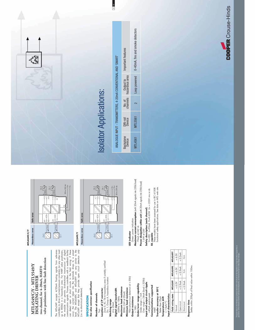
MT
L45
49/C
/Y -
MT
L55
49/Y
ISO
LAT
ING
DR
IVE
R
two-
chan
nel,
for
4–20
mA
, HA
RT
®
valv
e po
siti
oner
s w
ith
line
faul
t de
tect
ion
The
MTL
x549
ac
cept
s 4/
20m
A
float
ing
sign
als
from
sa
fe-a
rea
cont
rolle
rs t
o dr
ive
2 cu
rren
t/pr
essu
re c
onve
rters
(or
any
oth
er lo
ad
up t
o 80
0)
in a
haz
ardo
us a
rea.
For
HA
RT v
alve
pos
ition
ers,
th
e m
odul
e al
so
perm
its
bi-d
irect
iona
l tra
nsm
issi
on
of
digi
tal
com
mun
icat
ion
sign
als.
Pro
cess
con
trolle
rs w
ith a
rea
dbac
k fa
cilit
y ca
n de
tect
op
en
or
shor
t ci
rcui
ts in
th
e fie
ld
wiri
ng:
if th
ese
occu
r, th
e cu
rren
t ta
ken
into
th
e te
rmin
als
drop
s to
a
pres
et
leve
l. Th
e M
TL45
49C
an
d M
TLx5
49Y
are
very
si
mila
r to
th
e M
TLx5
49
exce
pt
that
th
ey
prov
ide
open
ci
rcui
t de
tect
ion
only
(i.
e. n
o sh
ort-c
ircui
t det
ectio
n).
SPEC
IFIC
ATI
ON
See
als
o c
om
mon s
pec
ific
ation
Num
ber
of
channel
s
Two
Loca
tion o
f I/
P c
onve
rter
Zo
ne 0
, IIC
, T4–
6 ha
zard
ous
area
if s
uita
bly
certi
fied
D
iv. 1
, Gro
up A
, haz
ardo
us lo
catio
nW
ork
ing r
ange
4
to 2
0mA
Dig
ital si
gnal bandw
idth
50
0Hz
to 1
0kH
zM
ax
imum
load r
esis
tance
80
0 (1
6V a
t 20m
A)
Min
imum
load r
esis
tance
90
(sho
rt-ci
rcui
t det
ectio
n at
< 5
0)
Outp
ut
resi
stance
>
1MU
nder
/ove
r ra
nge
capabili
ty
Und
er r
ange
= 1
mA
O
ver
rang
e =
24m
A (l
oad
520
)In
put
and o
utp
ut
circ
uit r
ipple
<4
0μA
pea
k-to
-pea
kCom
munic
ations
support
edH
ART
Transf
er a
ccura
cy a
t 20°C
Be
tter
than
20μ
ATe
mper
atu
re d
rift
<
1.0μ
A/°
CIn
put
chara
cter
istics
Fiel
d w
irin
g s
tate
MTL
45
49
MTL
45
49
CM
TL4
54
9Y
Nor
mal
< 6.
0V<
6.0V
< 6.
0V
Ope
n-ci
rcui
t<
0.9m
A<
0.9m
A<
0.5m
A
Shor
t-circ
uit
< 0.
9mA
N.A
.N
.A.
Res
ponse
tim
e
Settl
es w
ithin
200
μA o
f fin
al v
alue
with
in 1
00m
s
Haza
rdous
are
aSa
fe a
rea
������
��� ����
��=� 3
��
� �
��
� ���=� 3
1$�
1$�
1$�
1$�
���=� 3
�=� 3
& � � � �
' ( )
� �� �� � ��
�
�
�
�
MTL
45
49/C
/Y
Haza
rdous
are
aSa
fe a
rea
�=� 3
��
� �
��
� �
� �=� 3
1$�
1$�
1$�
1$�
��=� 3
�=� 3
������
��� ����
� �
& � � � �
�
�
�
�
) ( '�� �� �
� ��
MTL
55
49/Y
LED
indic
ato
rG
reen
: pow
er in
dica
tion
Max
imum
cur
rent
con
sum
ptio
n (w
ith 2
0mA
sig
nals
into
250
load
)
70m
A a
t 24V
dc
Pow
er d
issi
patio
n w
ithin
uni
t (w
ith 2
0mA
sig
nals
into
250
load
)
1.6W
at 2
4VSa
fety
des
crip
tion (
each
channel
)
V o=2
8V
Io=9
3mA
Po
=0.6
5W
Um =
253
V rm
s or
dc
SIL
capable
Thes
e m
odel
s ha
ve b
een
asse
ssed
for
use
in IE
C 6
1508
fu
nctio
nal s
afet
y ap
plic
atio
ns. S
ee d
ata
on M
TL w
eb s
ite.
Back
plan
eDe
vice
MTL
4561
DIN-
rail
Devi
ce
MTL
5561
No. o
f ch
anne
ls
2
Impo
rtant
feat
ures
0-40
mA,
fire
and
sm
oke
dete
ctor
s
Outp
ut to
haza
rdou
s ar
ea
Loop
pow
ered
ANAL
OGUE
INPU
T - T
RANS
MIT
TERS
, 4-2
0mA
CONV
ENTI
ONAL
AND
‘SM
ART’
Isol
ator
App
licat
ions
:
The
giv
en d
ata
is o
nly
inte
nded
as
a pro
duct
des
crip
tion
and
shou
ld n
ot b
e re
gar
ded
as
a le
gal
war
ranty
of pro
per
ties
or
guar
ante
e. In
the
inte
rest
of
furt
her
tec
hnic
al d
evel
opm
ents
, w
e re
serv
e th
e ri
ght
to m
ake
des
ign
chan
ges
.
5455

MT
L45
61 –
MT
L55
61
FIR
E A
ND
SM
OK
E
DE
TE
CT
OR
IN
TE
RFA
CE
tw
o-ch
anne
l
The
MTL
x561
is
a lo
op-p
ower
ed 2
–cha
nnel
int
erfa
ce f
or u
se w
ith
conv
entio
nal
fire
and
smok
e de
tect
ors
loca
ted
in h
azar
dous
are
as.
In o
pera
tion,
the
trig
gerin
g of
a d
etec
tor
caus
es a
cor
resp
ondi
ng
chan
ge i
n th
e sa
fe–a
rea
curr
ent.
The
unit
feat
ures
rev
erse
inp
ut
pola
rity
prot
ectio
n, w
hile
‘no
-fail’
ear
th f
ault
dete
ctio
n on
eith
er li
ne
can
be p
rovi
ded
by c
onne
ctin
g an
ear
th le
akag
e de
tect
or to
term
inal
3
and/
or 6
.
SPEC
IFIC
ATI
ON
See
als
o c
om
mon s
pec
ific
ation
Num
ber
of
channel
sTw
o, fu
lly fl
oatin
g, lo
op p
ower
edLo
cation o
f fi
re a
nd s
mok
e det
ecto
rsZo
ne 0
, IIC
, T4–
6 ha
zard
ous
area
if s
uita
bly
certi
fied
Div.
1, G
roup
A, h
azar
dous
are
aIn
put
voltage
6 to
30V
dc
Curr
ent
range
1 to
40m
A, n
omin
al
Quie
scen
t sa
fe–a
rea c
urr
ent
at
20°C
(haz
ardo
us–a
rea
term
inal
s op
en c
ircui
t)<
400μ
A a
t Vin
= 2
4V p
er c
hann
elIn
tegra
l in
put
pola
rity
pro
tect
ion
Inpu
t circ
uit p
rote
cted
aga
inst
reve
rse
pola
rity
‘No-f
ail’
eart
h f
ault p
rote
ctio
nEn
able
d by
con
nect
ing
term
inal
s 3
and/
or 6
to a
n ea
rth
leak
age
dete
ctor
(see
not
es)
Faul
t on
eith
er li
ne o
f eac
h ch
anne
l pro
clai
med
: uni
t con
tinue
s w
orki
ngN
otes
: 1.
To
mai
ntai
n is
olat
ion
betw
een
the
two
chan
nels,
sep
arat
e ea
rth l
eaka
ge
dete
ctor
s ar
e ne
eded
.2.
The
ear
th le
akag
e de
tect
ors
intro
duce
a 1
00μA
, 1H
z rip
ple
to th
e fie
ld c
ircui
t.M
inim
um
outp
ut
voltage
Vout
at
20°C
For V
in
25V
: Vo
ut =
Vin
– (0
.38
x cu
rren
t in
mA
) – 2
VFo
r Vin
> 2
5V:
Vout
= 2
2.5V
– (0
.35
x cu
rren
t in
mA
)M
ax
imum
outp
ut
voltage
28V
from
300
Transf
er a
ccura
cy a
t 20°C
Bette
r th
an 4
00μA
Tem
per
atu
re d
rift
<
4μA
/°C
( 0°
C to
60°
C)
< 15
μA/°
C (–
20°C
to 0
°C)
Res
ponse
tim
e to
ste
p input
Settl
es to
with
in 5
% o
f fin
al v
alue
with
in 1
.5m
sPow
er d
issi
pation w
ithin
unit
0.7W
max
imum
at 2
4V w
ith 4
0mA
sig
nal (
each
cha
nnel
)0.
9W m
axim
um a
t 30V
with
40m
A s
igna
l (ea
ch c
hann
el)
Safe
ty d
escr
iption f
or
each
channel
V o
=28V
Io
=93m
A
Po=0
.65W
U
m =
253
V rm
s or
dc
Haza
rdous
are
aSa
fe a
rea
�� �� �� �
1$� 1$�
1$�
1$�
�& � � � �
�
�
�
�
����
���������
.�����$�����/�
��������0
.�����$�����/�
��������0
) ( '�� �� �
� ��
MTL
55
61
MTL
45
61
Haza
rdous
are
aSa
fe a
rea
�� �
� �� ��
1$� 1$�
1$�
1$�
& � � � �
' ( )
� �� �� � ��
�
�
�
�
����
���������
.�����$�����/�
��������0
.�����$�����/�
��������0
*Sig
nal p
lug
HA
Z1-3
is r
equi
red
for
acce
ss to
this
func
tion
Back
plan
eDe
vice
MTL
4575
MTL
4576
-THC
DIN-
rail
Devi
ce
MTL
5575
MTL
5576
-THC
No. o
f ch
anne
ls
1 2
Impo
rtant
feat
ures
Confi
gura
ble
linea
rised
con
verte
r, tri
pal
arm
, ear
ly b
urn-
out d
etec
t
Confi
gura
ble
linea
rised
con
verte
r,ea
rly b
urn-
out d
etec
t, cu
stom
opt
ions
Inpu
t fro
mha
zard
ous
area
Ther
moc
oupl
e or
m
V so
urce
s
Ther
moc
oupl
e or
m
V so
urce
s
TEM
PERA
TURE
INPU
T - T
HERM
OCOU
PLE
AND
mV
SOUR
CES,
THC
Back
plan
eDe
vice
MTL
4575
MTL
4576
-RTD
DIN-
rail
Devi
ce
MTL
5575
MTL
5576
-RTD
No. o
f ch
anne
ls
1 2
Impo
rtant
feat
ures
Confi
gura
ble
linea
rised
con
verte
r, tri
pal
arm
, ear
ly b
urn-
out d
etec
t
Confi
gura
ble
linea
rised
con
verte
r,ea
rly b
urn-
out d
etec
t, cu
stom
opt
ions
Inpu
t fro
mha
zard
ous
area
Pt, C
u, N
i sen
sors
2/
3/4
wire
Pt, C
u, N
i sen
sors
2/
3 w
ire
TEM
PERA
TURE
INPU
T -
RESI
STAN
CE S
ENSO
RS, R
TD
Isol
ator
App
licat
ions
:
The
giv
en d
ata
is o
nly
inte
nded
as
a pro
duct
des
crip
tion
and
shou
ld n
ot b
e re
gar
ded
as
a le
gal
war
ranty
of pro
per
ties
or
guar
ante
e. In
the
inte
rest
of
furt
her
tec
hnic
al d
evel
opm
ents
, w
e re
serv
e th
e ri
ght
to m
ake
des
ign
chan
ges
.
5657

The
MTL
x575
con
verts
a lo
w-le
vel d
c si
gnal
from
a te
mpe
ratu
re s
enso
r m
ount
ed i
n a
haza
rdou
s ar
ea i
nto
a 4/
20m
A c
urre
nt f
or d
rivin
g a
safe
-are
a lo
ad.
Softw
are
sele
ctab
le f
eatu
res
incl
ude
linea
risat
ion,
ra
ngin
g, m
onito
ring,
tes
ting
and
tagg
ing
for
all
ther
moc
oupl
e ty
pes
and
2-, 3
- or 4
-wire
RTD
s. (F
or th
erm
ocou
ple
appl
icat
ions
the
HA
Z-C
JC
plug
on
term
inal
s 1–
3 in
clud
es a
n in
tegr
al C
JC s
enso
r). C
onfig
urat
ion
is c
arrie
d ou
t us
ing
a pe
rson
al c
ompu
ter.
A s
ingl
e al
arm
out
put
is
prov
ided
and
may
be
conf
igur
ed fo
r hi
gh o
r lo
w p
roce
ss a
larm
or
to
prov
ide
notic
e of
ear
ly th
erm
ocou
ple
failu
re.
SPEC
IFIC
ATI
ON
See
als
o c
om
mon s
pec
ific
ation
Num
ber
of
channel
sO
neSi
gnal so
urc
eTH
C ty
pes
J, K,
T, E
, R, S
, B o
r N
to B
S 60
584
and
XKm
V in
put
RTD
s 2/
3/4-
wire
pla
tinum
to B
S 60
751
Pt
100
, Pt 5
00, P
t 100
0
Cu-
50 &
Cu-
53
Ni 1
00/5
00/1
000
DIN
437
60Lo
cation o
f si
gnal so
urc
eZo
ne 0
, IIC
, T4-
6 ha
zard
ous
area
Div
isio
n 1,
Gro
up A
, haz
ardo
us lo
catio
nIn
put
signal ra
nge
–75
to +
75m
V, o
r 0
to 4
00 (0
to 1
000
Pt &
Ni s
enso
rs)
Input
signal sp
an
3 to
150
mV,
or
10 to
400
(10
to 1
000
Pt &
Ni s
enso
rs)
RTD
ex
cita
tion c
urr
ent
200μ
A n
omin
alCold
junct
ion c
om
pen
sation
Aut
omat
ic o
r se
lect
able
Cold
junct
ion c
om
pen
sation e
rror
1.0°
CCom
mon m
ode
reje
ctio
n12
0dB
for
240V
at 5
0Hz
or 6
0Hz
(500
ms
resp
onse
)Se
ries
mode
reje
ctio
n40
dB fo
r 50
Hz
or 6
0Hz
Calib
ration a
ccura
cy (
at
20°C
)(incl
udes
hyst
eres
is,
non-l
inea
rity
and r
epea
tabili
ty)
In
puts
: (5
00m
s re
sponse
)m
V/TH
C:
± 15
μV o
r ±
0.05
% o
f inp
ut v
alue
(w
hich
ever
is g
reat
er)
RTD
: ±
80m
O
utp
ut:
±
11μA
Tem
per
atu
re d
rift
(ty
pic
al)
In
puts
:m
V/TH
C:
± 0.
003%
of i
nput
val
ue/°
CRT
D:
± 7m
/°C
O
utp
ut:
±
0.6μ
A/°
CEx
am
ple
of
calib
ration a
ccura
cy a
nd t
emper
atu
re d
rift
(RTD
input
- 5
00m
s re
sponse
)Sp
an:
250
Acc
urac
y:
± (0
.08/
250
+ 11
/160
00) x
100
%
=
0.1%
of s
pan
Tem
pera
ture
drif
t: ±
(0.0
07/2
50 x
160
00 +
0.6
) μA
/°C
= ±1
.0μA
/°C
Safe
ty d
rive
on s
enso
r fa
ilure
Ups
cale
, dow
nsca
le, o
r of
fEa
rly b
urn
out
Early
bur
nout
det
ectio
n fo
r th
erm
ocou
ples
(whe
n se
lect
ed)
Ala
rm tr
ips
whe
n lo
op r
esis
tanc
e in
crea
se is
> 5
0O
utp
ut
range
4 to
20m
A n
omin
al in
to 6
00 m
ax. (
dire
ct o
r re
vers
e)A
larm
outp
ut
(confi
gura
ble
)Re
lay
ON
in a
larm
, 250
mA
@ 3
5V m
axM
ax
imum
lea
d r
esis
tance
(TH
C)
600
Res
ponse
tim
eC
onfig
urab
le -
500
ms
defa
ult
(Acc
urac
y at
100
/200
ms
- con
tact
MTL
)LE
D indic
ato
rG
reen
: pow
er a
nd s
tatu
s in
dica
tion
Yello
w: a
larm
indi
catio
n, o
n w
hen
cont
acts
are
clos
edM
ax
imum
curr
ent
consu
mption (
with
20m
A s
igna
l)50
mA
at 2
4VPow
er d
issi
pation w
ithin
unit (
with
20m
A s
igna
l)1.
2W a
t 24V
Safe
ty d
escr
iption
Refe
r to
cer
tific
ate
for
para
met
ers.
Um
=253
V rm
s or
dc
Confi
gura
tor
A p
erso
nal c
ompu
ter
runn
ing
MTL
PC
S45
softw
are
with
a
PCL4
5USB
ser
ial i
nter
face
.
MT
L45
75 –
MT
L55
75
TE
MP
ER
ATU
RE
CO
NV
ER
TE
RT
HC
or
RT
D i
nput
+ A
larm
MTL
45
75
MTL
55
75
5859
MT
L45
76-R
TD
– M
TL
5576
-RT
DT
EM
PE
RAT
UR
E
CO
NV
ER
TE
RR
TD
/pot
enti
omet
er i
nput
, 2 c
h
The
MTL
x576
–RTD
co
nver
ts si
gnal
s fro
m
resi
stanc
e te
mpe
ratu
re
dete
ctor
s (R
TDs)
mou
nted
in a
haz
ardo
us a
rea,
into
4/2
0mA
cur
rent
s fo
r dr
ivin
g sa
fe-a
rea
load
s. S
oftw
are
sele
ctab
le f
eatu
res
incl
ude
inpu
t ty
pe a
nd c
hara
cter
isat
ion,
ran
ging
, m
onito
ring,
tes
ting
and
tagg
ing.
Con
figur
atio
n is
car
ried
out u
sing
a p
erso
nal c
ompu
ter.
The
MTL
x576
–RTD
is c
ompa
tible
with
2–
and
3–w
ire R
TD in
puts.
SPEC
IFIC
ATI
ON
See
als
o c
om
mon s
pec
ific
ation
Num
ber
of
channel
sTw
oSi
gnal so
urc
e2-
/3-w
ire R
TDs
to B
S 60
751
Pt
100
, Pt 5
00, P
t 100
0
Cu-
50 &
Cu-
53
Ni 1
00/5
00/1
000
DIN
437
60Lo
cation o
f si
gnal so
urc
eZo
ne 0
, IIC
, T4–
6 ha
zard
ous
area
Div
isio
n 1,
Gro
up A
, haz
ardo
us lo
catio
nIn
put
signal ra
nge
0 to
400
(0 to
400
0 P
t & N
i sen
sors
)In
put
signal sp
an
10 to
400
(10
to 1
000
Pt &
Ni s
enso
rs)
RTD
ex
cita
tion c
urr
ent
200μ
A n
omin
alCom
mon m
ode
reje
ctio
n12
0dB
for
240V
at 5
0Hz
or 6
0Hz
Seri
es m
ode
reje
ctio
n40
dB fo
r 50
Hz
or 6
0Hz
Calib
ration a
ccura
cy (
at
20°C
)(incl
udes
hyst
eres
is,
non-l
inea
rity
and r
epea
tabili
ty)
In
put:
±
80m
O
utp
ut:
±
16μA
Tem
per
atu
re d
rift
(ty
pic
al)
In
put:
±
7m/°
C
Outp
ut:
±
0.6μ
A/°
CEx
am
ple
of
calib
ration a
ccura
cy a
nd t
emper
atu
re d
rift
(RTD
input)
Span
: 25
0A
ccur
acy:
±
(0.0
8/25
0 +
16/1
6000
) x 1
00%
= 0.
13%
of s
pan
Tem
pera
ture
drif
t: ±
(0.0
07/2
50 x
160
00 +
0.6
) μA
/°C
= ±1
.0μA
/°C
Safe
ty d
rive
on s
enso
r fa
ilure
Ups
cale
, dow
nsca
le, o
r of
fO
utp
ut
range
4 to
20m
A n
omin
al in
to 3
00 m
ax. (
dire
ct o
r re
vers
e)Res
ponse
tim
eC
onfig
urab
le -
500
ms
defa
ult
(Acc
urac
y at
100
/200
ms
- con
tact
MTL
)
LED
indic
ato
rG
reen
: pow
er a
nd s
tatu
s in
dica
tion
Yello
w: o
ne p
rovi
ded
for
chan
nel s
tatu
sRe
d: a
larm
indi
catio
nPow
er r
equir
emen
t, V
s w
ith 2
0m
A s
ignal
60m
A a
t 24V
Pow
er d
issi
pation w
ithin
unit w
ith 2
0m
A s
ignal
1.4W
at 2
4VIs
ola
tion
Func
tiona
l cha
nnel
–cha
nnel
isol
atio
n fo
r sa
fe a
nd h
azar
dous
–ar
ea c
ircui
tsSa
fety
des
crip
tion
Refe
r to
cer
tific
ate
for
para
met
ers.
Um
=253
V rm
s or
dc
Confi
gura
tor
A p
erso
nal c
ompu
ter
runn
ing
MTL
PC
S45
softw
are
with
a
PCL4
5USB
ser
ial i
nter
face
.
Haza
rdous
are
aSa
fe a
rea
1�%��/������%
������
����
� �=� 3����
�=� 3
1$�
1$�
������
��� ����
�
1$�
1$�
,!���
,!���
��
& � � � �
�
��
) ( '�� �� �
� ��
MTL
55
76-R
TD
MTL
45
76-R
TD
Haza
rdous
are
aSa
fe a
rea
������
��� ����
1�%��/������%
������
����
��=� 3����
�=� 3
�
1$�
1$�
1$�
1$�
,!���
,!���
��& � � � �
' ( )
� �� �� � ��
�
��
The
giv
en d
ata
is o
nly
inte
nded
as
a pro
duct
des
crip
tion
and
shou
ld n
ot b
e re
gar
ded
as
a le
gal
war
ranty
of pro
per
ties
or
guar
ante
e. In
the
inte
rest
of
furt
her
tec
hnic
al d
evel
opm
ents
, w
e re
serv
e th
e ri
ght
to m
ake
des
ign
chan
ges
.
Haza
rdous
are
aSa
fe a
rea
��
�
�,!���
,!���
1�%��/������%
������
������
��� ����
����
3���
�=� 3
� �
& � � � ��
�
) ( '�� �� �
� ��
Haza
rdous
are
aSa
fe a
rea

MT
L45
76-T
HC
– M
TL
5576
-TH
CT
EM
PE
RAT
UR
E
CO
NV
ER
TE
Rm
V/T
HC
inp
ut, 2
ch
The
MTL
x576
–TH
C
conv
erts
low
–lev
el d
c si
gnal
s fro
m te
mpe
ratu
re
sens
ors
mou
nted
in
a ha
zard
ous–
area
int
o 4/
20m
A c
urre
nts
for
driv
ing
safe
–-ar
ea
load
s.
Softw
are
sele
ctab
le
feat
ures
in
clud
e lin
earis
atio
n fo
r sta
ndar
d th
erm
ocou
ple
type
s, r
angi
ng,
mon
itorin
g,
testi
ng a
nd t
aggi
ng.
Con
figur
atio
n is
car
ried
out
usin
g a
pers
onal
co
mpu
ter.
The
haza
rdou
s–ar
ea c
onne
ctio
ns i
nclu
de c
old–
junc
tion
com
pens
atio
n an
d do
not
nee
d to
be
orde
red
sepa
rate
ly.
SPEC
IFIC
ATI
ON
See
als
o c
om
mon s
pec
ific
ation
Num
ber
of
channel
sTw
oSi
gnal so
urc
eTH
C ty
pes
J, K,
T, E
, R, S
, B o
r N
to B
S 60
584
and
XKm
V in
put
Loca
tion o
f si
gnal so
urc
eZo
ne 0
, IIC
, T4–
6 ha
zard
ous
area
Div
isio
n 1,
Gro
up A
, haz
ardo
us lo
catio
nIn
put
signal ra
nge
–75
to +
75m
VIn
put
signal sp
an
3 to
150
mV
Cold
junct
ion c
om
pen
sation
Aut
omat
ic o
r se
lect
able
Cold
junct
ion c
om
pen
sation e
rror
1.0°
CCom
mon m
ode
reje
ctio
n12
0dB
for
240V
at 5
0Hz
or 6
0Hz
Seri
es m
ode
reje
ctio
n40
dB fo
r 50
Hz
or 6
0Hz
Calib
ration a
ccura
cy (
at
20°C
)(incl
udes
hyst
eres
is,
non-l
inea
rity
and r
epea
tabili
ty)
In
put:
±1
5μV
or ±
0.05
% o
f inp
ut v
alue
whi
chev
er is
gre
ater
)
Outp
ut:
±1
6μA
Tem
per
atu
re d
rift
(ty
pic
al)
In
put:
±0
.003
% o
f inp
ut v
alue
/°C
O
utp
ut:
±0
.6μA
/°C
Safe
ty d
rive
on s
enso
r burn
out
Ups
cale
, dow
nsca
le, o
r of
fO
utp
ut
range
4 to
20m
A n
omin
al in
to 3
00 m
ax. (
dire
ct o
r re
vers
e)M
ax
imum
lea
d r
esis
tance
300
Res
ponse
tim
eC
onfig
urab
le -
500
ms
defa
ult
(Acc
urac
y at
100
/200
ms
- con
tact
MTL
)
LED
indic
ato
rG
reen
: pow
er a
nd s
tatu
s in
dica
tion
Yello
w: o
ne p
rovi
ded
for
chan
nel s
tatu
sRe
d: a
larm
indi
catio
n P
ow
er r
equir
emen
t, V
s w
ith 2
0m
A s
ignal
60m
A a
t 24V
Pow
er d
issi
pation w
ithin
unit w
ith 2
0m
A s
ignal
1.4W
at 2
4VIs
ola
tion
Func
tiona
l iso
latio
n ch
anne
l–ch
anne
l for
saf
e an
d ha
zard
ous–
area
circ
uits.
Safe
ty d
escr
iption
Refe
r to
cer
tific
ate
for
para
met
ers.
Um
=253
V rm
s or
dc
Confi
gura
tor
A p
erso
nal c
ompu
ter
runn
ing
MTL
PC
S45
softw
are
with
a
PCL4
5USB
ser
ial i
nter
face
.
Haza
rdous
are
aSa
fe a
rea
1�%��/������%
������
����
� �=� 3����
�=� 3
1$�
1$�
������
��� ����
�
� �� �1$�
1$�
�
�
��
& � � � ��
�
�
) ( '�� �� �
� ��
MTL
55
76-T
HC
MTL
45
76-T
HC
Haza
rdous
are
aSa
fe a
rea
������
��� ����
�
1�%��/������%
������
����
��=� 3����
�=� 3
�
�� �1$�
1$�
1$�
1$�
�
�
��& � � � �
' ( )
� �� �� � ��
�
�
�
Back
plan
eDe
vice
MTL
4599
MTL
4599
N
DIN-
rail
Devi
ce
MTL
5599
MPA
5500
MTL
5991
MTL
5500
pow
erbu
s ki
t
Impo
rtant
feat
ures
Dum
my
isol
ator
mod
ules
for s
ecur
ing
spar
e ca
ble
core
s
Feed
-thr
ough
for n
on-IS
sig
nals
ont
o ba
ckpl
ane
Mai
ns p
ower
sup
ply
for i
ndiv
idua
l MTL
5500
mod
ule
Mai
ns p
ower
sup
ply,
24V
, 2A
capa
city
Link
s po
wer
to 8
, 16,
24,
32
MTL
5500
mod
ules
Stan
dard
bac
kpla
nes
for 4
, 8, 1
6, 2
4 M
TL45
00 m
odul
es
Hard
war
e ad
apto
r for
con
figur
atio
n of
con
verte
r mod
ules
, to-
geth
er w
ith p
c so
ftwar
e
GENE
RAL
PURP
OSE
MOD
ULES
AND
ACC
ESSO
RIES
Isol
ator
App
licat
ions
:
PCL4
5USB
/ PC
S45
CPSx
x
Othe
r mou
ntin
g an
d co
nnec
tion
acce
ssor
ies
for b
oth
prod
uct r
ange
s ar
e id
entifi
ed w
ithin
the
follo
win
g pa
ges
The
giv
en d
ata
is o
nly
inte
nded
as
a pro
duct
des
crip
tion
and
shou
ld n
ot b
e re
gar
ded
as
a le
gal
war
ranty
of pro
per
ties
or
guar
ante
e. In
the
inte
rest
of
furt
her
tec
hnic
al d
evel
opm
ents
, w
e re
serv
e th
e ri
ght
to m
ake
des
ign
chan
ges
.
6061
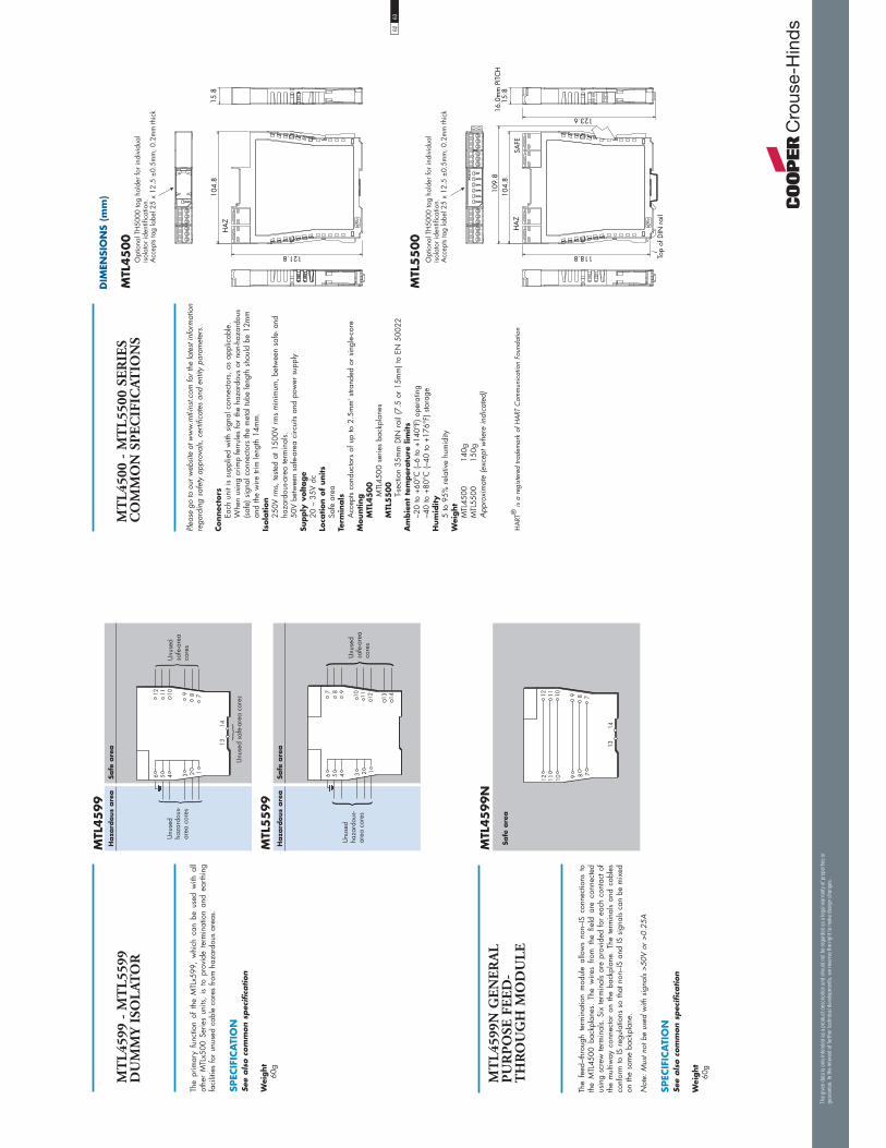
The
prim
ary
func
tion
of t
he M
TLx5
99,
whi
ch c
an b
e us
ed w
ith a
ll ot
her
MTL
x500
Ser
ies
units
, is
to
prov
ide
term
inat
ion
and
earth
ing
faci
litie
s fo
r un
used
cab
le c
ores
from
haz
ardo
us a
reas
.
SPEC
IFIC
ATI
ON
See
als
o c
om
mon s
pec
ific
ation
Wei
ght
60g
MT
L45
99 -
MT
L55
99D
UM
MY
ISO
LAT
OR
Haza
rdous
are
aSa
fe a
rea
& � � � �
' ( )
� �� �� � ��
>%����
$�?������,
���������
>%����
����,����
�����
Haza
rdous
are
aSa
fe a
rea
& � � � �
�� �� � ) ( '
>%����
$�?������,
���������
>%����
����,����
�����
>%��������,���������
� ��
MTL
45
99
MTL
55
99
Safe
are
a
�� �� � ) ( '
� ��
) ( '
�� �� �
MT
L45
99N
GE
NE
RA
L
PU
RP
OSE
FE
ED
-T
HR
OU
GH
MO
DU
LE
The
feed
–thr
ough
ter
min
atio
n m
odul
e al
low
s no
n–IS
con
nect
ions
to
the
MTL
4500
bac
kpla
nes.
The
wire
s fro
m t
he f
ield
are
con
nect
ed
usin
g sc
rew
term
inal
s. S
ix te
rmin
als
are
prov
ided
for
each
con
tact
of
the
mul
tiway
con
nect
or o
n th
e ba
ckpl
ane.
The
ter
min
als
and
cabl
es
conf
orm
to IS
reg
ulat
ions
so
that
non
–IS
and
IS s
igna
ls ca
n be
mix
ed
on th
e sa
me
back
plan
e.
Not
e: M
ust n
ot b
e us
ed w
ith s
igna
ls >5
0V o
r >0
.25A
SPEC
IFIC
ATI
ON
See
als
o c
om
mon s
pec
ific
ation
Wei
ght
60g
MTL
45
99N
6263
MT
L45
00 -
MT
L55
00 S
ER
IES
C
OM
MO
N S
PE
CIF
ICAT
ION
S
Plea
se g
o to
our
web
site
at w
ww
.mtl-
inst.
com
for t
he la
test
info
rmat
ion
rega
rdin
g sa
fety
app
rova
ls, c
ertif
icat
es a
nd e
ntity
par
amet
ers.
Connec
tors
Each
uni
t is
supp
lied
with
sig
nal c
onne
ctor
s, a
s ap
plic
able
.W
hen
usin
g cr
imp
ferr
ules
for
the
haza
rdou
s or
non
-haz
ardo
us
(saf
e) s
igna
l con
nect
ors
the
met
al tu
be le
ngth
sho
uld
be 1
2mm
an
d th
e w
ire tr
im le
ngth
14m
m.
Isola
tion
250V
rm
s, te
sted
at 1
500V
rm
s m
inim
um, b
etw
een
safe
- and
ha
zard
ous-a
rea
term
inal
s.50
V be
twee
n sa
fe-a
rea
circ
uits
and
pow
er s
uppl
ySu
pply
voltage
20 –
35V
dc
Loca
tion o
f units
Safe
are
aTe
rmin
als
Acc
epts
cond
ucto
rs o
f up
to 2
.5m
m2 s
trand
ed o
r si
ngle
-cor
eM
ounting
MTL
45
00
M
TL45
00 s
erie
s ba
ckpl
anes
MTL
55
00
T-s
ectio
n 35
mm
DIN
rai
l (7.
5 or
15m
m) t
o EN
500
22A
mbie
nt
tem
per
atu
re lim
its
–20
to +
60°C
(–6
to +
140°
F) o
pera
ting
–40
to +
80°C
(–40
to +
176°
F) s
tora
geH
um
idity
5 to
95%
rel
ativ
e hu
mid
ityW
eight
MTL
4500
14
0gM
TL55
00
150g
App
roxi
mat
e (e
xcep
t whe
re in
dica
ted)
DIM
ENSI
ON
S (m
m)
HA
RT®
is a
reg
iste
red
trade
mar
k of
HA
RT C
omm
unic
atio
n Fo
unda
tion
MTL
45
00
�&4 ��.1@
+3�A
@3B
��4(
�)4(
��4(
�� 4&
��(4( .������C����
�
���
��
���
���
���
�������
*����%��.@���/$���������%��8�����
�����������%���������%4
3��������/��#����5��4�D4� 74� �$���
@3B
��4(
��4(
���4(
�
���
��
���
���
���
*����%��.@���/$���������%��8�����
�����������%���������%4
3��������/��#����5��4�D4� 74� �$���
MTL
55
00
The
giv
en d
ata
is o
nly
inte
nded
as
a pro
duct
des
crip
tion
and
shou
ld n
ot b
e re
gar
ded
as
a le
gal
war
ranty
of pro
per
ties
or
guar
ante
e. In
the
inte
rest
of
furt
her
tec
hnic
al d
evel
opm
ents
, w
e re
serv
e th
e ri
ght
to m
ake
des
ign
chan
ges
.

PC
S45/
PC
L45
USB
CO
NFI
GU
RAT
OR
FO
R M
TL
CO
NV
ER
TE
RS
SPEC
IFIC
ATI
ON
PCL4
5U
SB h
ard
ware
Loca
tion
Safe
are
aConnec
tions
PC s
ide:
USB
B(F
) soc
ket
Conve
rter
si
de:
ca
ble
with
3.
5mm
ja
ckpl
ug,
3-po
le
for
MTL
4500
and
MTL
5500
ser
ies
conv
erte
rs.
An
adap
ter
cabl
e is
pr
ovid
ed fo
r ot
her
earli
er M
TL c
onve
rters
.Cable
len
gth
sC
onve
rter
side
(fitt
ed):
1.5m
USB
cab
le A
(M) t
o B(
M) (
supp
lied)
: 2m
Am
bie
nt
tem
per
atu
re lim
its
–10°
C to
+60
°C o
pera
ting
–20°
C to
+70
°C s
tora
geH
um
idity
5 to
95%
rel
ativ
e hu
mid
ity (n
on-c
onde
nsin
g)W
eight
200g
PCS4
5 C
onfi
gura
tion s
oft
ware
Com
patib
le w
ith W
indo
ws
2000
or
Win
dow
s XP
.C
onsu
lt M
TL fo
r op
erat
ion
with
any
oth
er o
pera
ting
syste
m,
e.g.
Win
dow
s Vi
sta™
.So
ftw
are
med
ium
PCS4
5 su
pplie
d on
CD
Upd
ates
are
ava
ilabl
e at
ww
w.m
tl-in
st.co
mRec
om
men
ded
min
imum
PC c
onfi
gura
tion
Mic
roso
ft W
indo
ws
2000
or
Win
dow
s XP
20M
B of
ava
ilabl
e ha
rd d
isc
spac
eC
D R
OM
driv
eA
vaila
ble
USB
por
t Pr
inte
r (lo
cal o
r ne
twor
k) ,����
E������/
4�
�������
�������
��������������� !����
"#�$����%
� &'�( #)'���*�
�+,�-.-/(,�/ .�0 ( � 10� 22.�/ (�+1�/+10�(�+13�3--� 22,+4 .
�� �� ��� ����
�
+=C6���
� 0-��1��+/56#7��-,#
18
�����13(,6#-1(3��#)9
>+2��%%�����
>���������
��#�����8����
9.��'
9.��'�
�%�������%/��%�
9.��'
9.��'�
9.���
9.���
�1+��
����!���1�
Safe
are
a
The
MPA
5500
ena
bles
any
MTL
5500
Ser
ies
mod
ule
that
is n
orm
ally
po
wer
ed fr
om a
nom
inal
24V
DC
sup
ply
(i.e.
thos
e th
at a
re n
ot lo
op-
pow
ered
) to
be p
ower
ed fr
om a
hig
h-vo
ltage
AC
sup
ply.
It pl
ugs
into
the
pow
er s
ocke
t (te
rmin
als
13 a
nd 1
4) o
f an
MTL
5500
m
odul
e an
d cl
ips
secu
rely
ont
o th
e m
odul
e ho
usin
g. T
he 2
5V D
C
pow
er o
utpu
t fro
m th
e ad
apto
r is
suf
ficie
nt to
sup
ply
a si
ngle
mod
ule
and
can
be c
onne
cted
to a
ny n
orm
al A
C p
ower
sou
rce.
��������%��
�� �8����
9�3��
3�����-�����
����� �8����
9�3��
��
�
��4(
��(4(
�
31�%����
.������C����
MPA
5500
A.C
. PO
WE
R A
DA
PT
OR
SPEC
IFIC
ATI
ON
Input
voltage
85 –
265
V A
C,
(45–
65H
z)Ef
fici
ency
71%
typ.
at 2
30V
AC
Pow
er d
issi
pation
1.2W
typ
at 2
30V
AC
.In
put
term
inals
Cag
e-cl
amp
term
inal
s ac
com
mod
atin
g co
nduc
tors
up
to 1
.5m
m2 s
trand
ed o
r 16
AWG
sin
gle-
core
Input
pro
tect
ion
inte
rnal
fuse
, not
use
r se
rvic
eabl
eO
utp
ut
voltage
25Vd
c ±
10%
Outp
ut
curr
ent
120m
A a
t 25V
Am
bie
nt
tem
per
atu
reO
pera
ting:
–2
0 to
+60
°CSt
orag
e:
–40
to +
80°C
Mounting
Plug
s in
to a
nd c
lips
onto
MTL
5500
Ser
ies
I/O
mod
ule
It is
not
for
use
with
any
equ
ipm
ent o
ther
than
MTL
5500
.H
um
idity
5 to
95%
rel
ativ
e hu
mid
ityM
echanic
al
Ingr
ess
Prot
ectio
n:
IP20
Mat
eria
l:
poly
carb
onat
eW
eigh
t:
28g
appr
ox.
Standard
s co
mplia
nce
EN 6
1326
, EN
610
10
The
PCS4
5/PC
L45U
SB c
onfig
urat
or a
llow
s M
TL c
onve
rters
to
be
conf
igur
ed f
rom
a s
tand
ard
PC r
unni
ng a
Mic
roso
ft® W
indo
ws®
op
erat
ing
syste
m. I
t com
pris
es P
C so
ftwar
e, p
rovi
ded
on a
CD
(PC
S45)
, an
d an
ATE
X ce
rtifie
d in
terfa
cing
link
(PC
L45U
SB).
Con
verte
rs c
an b
e co
nfig
ured
fro
m th
e sa
fe a
rea,
whi
le o
n-lin
e, a
nd c
onfig
urat
ions
can
be
sav
ed to
dis
k an
d pr
inte
d ou
t whe
n re
quire
d. It
is s
uita
ble
for
use
with
MTL
4000
, MTL
4500
, MTL
5000
and
MTL
5500
ser
ies
prod
ucts
.
6465
MT
L59
91
24V
DC
PO
WE
R S
UP
PLY
SPEC
IFIC
ATI
ON
Pow
er s
upply
85 to
264
V ac
47
to 6
3Hz
Pow
er d
issi
pation w
ithin
unit
7.2W
@ 2
AM
ounting
35m
m D
IN (t
op h
at) r
ail
Outp
ut
voltage
24V
dc n
om
(23.
64 m
in/2
4.36
max
)O
utp
ut
curr
ent
2A m
axim
um
(1.7
A w
ith <
105V
ac
inpu
t)LE
D indic
ato
rsG
reen
: Po
wer
indi
catio
nW
eight
310g
Am
bie
nt
tem
per
atu
reO
pera
ting
tem
pera
ture
–1
0°C
to +
50°C
Stor
age
tem
pera
ture
–4
0°C
to +
85°C
Term
inals
Cag
e cl
amp
type
acc
omm
odat
ing
cond
ucto
rs u
p to
2.5
mm
2 ,str
ande
d or
sin
gle-
core
Note
: Se
greg
atio
n be
twee
n ha
zard
ous
and
safe
are
a w
iring
mus
t be
mai
ntai
ned.
Safe
are
a
� � & ' (
� �
� �
�(;�4��F<
�� 4&;�4�'F<
); 4��F<
(;�4�F<
��
��&'(
A q
uick
and
eas
y w
ay t
o di
strib
ute
DC
pow
er t
o M
TL55
00 S
erie
s m
odul
es.
Each
pow
erbu
s ki
t inc
lude
s 4
sing
le fe
rrul
es,
4 tw
in fe
rrul
es
and
2 in
sula
tion
disp
lace
men
t con
nect
ors
(Sco
tchl
ok).
SPEC
IFIC
ATI
ON
Ava
ilable
in 4
dif
fere
nt
length
s:PB
- 8T
=
8 co
nnec
tors
and
loop
sPB
- 16
T
= 16
con
nect
ors
and
loop
sPB
- 24
T
= 24
con
nect
ors
and
loop
sPB
- 32
T
= 32
con
nect
ors
and
loop
sIn
sula
tion m
ate
rial :
PVC
Conduct
or
:24
stra
nds
of 0
.2m
m d
ia (0
.75m
m2 ) s
tand
ard
copp
erIn
sula
tion t
hic
knes
s :
0.5
to 0
.8 m
mCurr
ent
rating :
12
A m
axO
per
ating t
emper
atu
re r
ange
:- 2
0ºC
to +
60ºC
Max
vol
tage
dro
p o
n 32 m
odul
es d
raw
ing 1
30m
A m
ax
:
0.5V
MT
L55
00 S
ER
IES
PO
WE
RB
US
KIT
SP
B -
8T,
16T,
24T,
32T
��
*����%���%�������%
�������� �%�
��%%������
5�
CH
OO
SIN
G A
PO
WER
BU
S K
ITC
hoos
e a
pow
erbu
s w
here
the
num
ber o
f pow
er p
lugs
is g
reat
er th
an
or e
qual
to th
e nu
mbe
r of i
sola
tors
to b
e po
wer
ed a
nd if
nec
essa
ry c
ut
the
pow
erbu
s to
the
requ
ired
num
ber
of te
rmin
atio
ns.
Note
: To
red
uce
the
risk
of
exce
ssiv
e vo
ltage
dro
p o
r ove
rcurr
ent
do n
ot
connec
t pow
erbuse
s in
ser
ies.
A D
IN-ra
il m
ount
ed u
nit f
or lo
catio
ns w
here
a d
c su
pply
is n
ot re
adily
av
aila
ble.
Th
e w
ide
inpu
t po
wer
sup
ply
rang
e m
akes
thi
s un
it un
iver
sally
app
licab
le a
nd th
e 24
V dc
, 2
A o
utpu
t will
driv
e a
usef
ul
num
ber
of M
TL50
00 a
nd M
TL55
00 s
erie
s m
odul
es.
The
giv
en d
ata
is o
nly
inte
nded
as
a pro
duct
des
crip
tion
and
shou
ld n
ot b
e re
gar
ded
as
a le
gal
war
ranty
of pro
per
ties
or
guar
ante
e. In
the
inte
rest
of
furt
her
tec
hnic
al d
evel
opm
ents
, w
e re
serv
e th
e ri
ght
to m
ake
des
ign
chan
ges
.

SPEC
IFIC
ATI
ON
Const
ruct
ion
Gla
ss r
einf
orce
d po
lyca
rbon
ate
base
- D
X070
Gla
ss r
einf
orce
d po
lyes
ter
base
- D
X170
, DX4
30Tr
ansp
aren
t pol
ycar
bona
te li
dPro
tect
ion
Dus
t-tig
ht a
nd w
ater
-jet p
roof
to IE
C52
9:IP
65Li
d f
ixin
gC
aptiv
e fix
ing
scre
ws
Wei
ght
(ex
cludin
g b
arr
iers
/iso
lato
rs)
kg
DX0
70
0.8
DX1
70
2.6
DX4
30
4.1
Item
s pro
vided
DIN
rai
l - fi
tted
ETL7
000
Earth
term
inal
s (2
x) -
fitte
d"T
ake
care
IS"
front
adh
esiv
e la
bel
Cab
le tr
unki
ng (e
xcep
t DX0
70)
Note
: Is
olato
rs a
re n
ot inc
luded
.M
ounting
Wal
l fix
ing
lugs
pro
vide
d. F
or fu
rther
det
ails
refe
r to
INM
5500
.Ta
ggin
g a
nd e
art
h r
ail
Acc
omm
odat
es M
TL55
00 S
erie
s ac
cess
orie
s.Per
mitte
d loca
tion
• Sa
fe (n
on-h
azar
dous
) are
a
MT
L55
00 S
ER
IES
EN
CLO
SUR
ES
DIM
ENSI
ON
S (m
m)
AN
D M
OU
NTI
NG
Note
: N
. A
mer
ica/
Can
ada
- En
clos
ures
are
rat
ed N
EMA
4X
so
can
be u
sed
in C
lass
1,
Div
isio
n 2
(gas
es)
loca
tion,
but
che
ck
with
loc
al r
equi
rem
ents
and
ensu
re a
ll ca
ble
entri
es a
lso c
onfo
rm.
Add
ition
al w
arni
ng la
bel w
ill b
e re
quire
d on
or
near
the
encl
osur
e,
see
insta
llatio
n de
tails
. N
ot s
uita
ble
for
Cla
ss I
I or
III,
Div
isio
n 2
haza
rdou
s lo
catio
ns.
Appro
xim
ate
capaci
ties
(on
DIN
rai
l bet
wee
n ea
rth te
rmin
als)
* Us
e th
ese
figur
es w
hen
IMB5
7 m
ount
ing
bloc
ks fo
r tag
ging
/ear
th a
re in
clude
d.
Am
bie
nt
tem
per
atu
re lim
its
Dep
ende
nt o
n un
its fi
tted.
See
instr
uctio
n m
anua
l IN
M55
00.
� �;�%����<
��
���:�
���
�'
� '
'
�'�
��'
�('
G�4�
�(�
��';�%����<
.������C����
�'
��)
�
����
&
)
)�
�'
G'4�
���:�
�(�
��';�%����<
.������C����
�'
( (
��
�
��
�'&
��)
�
G'4�
�����
Num
ber
of
MTL
55
00 iso
lato
rs
DX
070
4(2
)*
DX
170
10(8
)*
DX
430
26(2
4)*
6667
MT
L55
00 S
ER
IES
AC
CE
SSO
RIE
S
MTL
5500
Ser
ies
isol
ator
s m
ount
qui
ckly
and
eas
ily o
nto
stand
ard
DIN
ra
il. A
com
preh
ensi
ve r
ange
of
acce
ssor
ies
sim
plifi
es e
arth
ing
and
tagg
ing
arra
ngem
ents.
(�
� �
�(
&&
��
��
�
�& �
� �
�& �
� �
�
��
�
��
�
�4�
'
���
���
���
���
�
.@��
�92�'
A��'
@3B�,
@3B�,&.@
�
.3H�'
.H��'
+3�',)
+3��,��
A�2�'+
�I��
A.9'
.@�
��C,����
�����������
H,������%��C����
See
als
o‘M
TL5
500 S
erie
s pow
erbus
kits'
MO
UN
TIN
GTH
R2 D
IN r
ail,
1m
len
gth
DIN
rai
l to
EN50
022;
BS5
584;
DIN
4627
7
MS0
10 D
IN r
ail
module
space
r, 1
0m
m,
pack
of
5G
rey
spac
er, o
ne r
equi
red
betw
een
each
MTL
5995
and
any
ad
jace
nt m
odul
e on
a D
IN r
ail,
to p
rovi
de 1
0mm
air-
circ
ulat
ion
spac
e be
twee
n m
odul
es
EARTH
RA
IL A
ND
TA
G S
TRIP
IMB5
7 I
nsu
lating m
ounting b
lock
One
req
uire
d at
eac
h en
d of
a ta
ggin
g str
ip/e
arth
rai
l. Su
itabl
e fo
r lo
w-p
rofil
e (7
.5m
m) a
nd h
igh-
prof
ile (1
5mm
) sym
met
rical
D
IN r
ail.
ETM
7 E
art
h t
erm
inal,
bag o
f 5
0Fo
r te
rmin
atin
g ca
ble
scre
ens
and
0V r
etur
ns o
n th
e ER
L7
earth
rai
l. Fo
r ca
bles
4
mm
2 . Exa
ct d
imen
sion
dep
ende
nt o
n m
anuf
actu
rer.
TAG
57 T
aggin
g s
trip
, 1m
len
gth
Cut
to s
ize.
Sup
plie
d w
ith ta
ggin
g str
ip la
bel s
uita
ble
for
MTL
5000
or
MTL
5500
mod
ules
.
TGL5
7 T
aggin
g s
trip
label
s, s
et o
f 10 x
0.5
mSp
ares
rep
lace
men
t, fo
r us
e w
ith T
AG
57 ta
ggin
g str
ip. S
uita
ble
for
MTL
5000
or
MTL
5500
mod
ules
.
IND
IVID
UA
L IS
OLA
TOR ID
ENTI
FICA
TIO
NTH
5000 t
ag h
old
ers
Each
isol
ator
may
be
fitte
d w
ith a
cle
ar p
lasti
c ta
g ho
lder
, as
show
n be
low
. Ord
er T
H50
00, p
ack
of 2
0.
CO
NN
ECTO
RS
Each
MTL
5500
uni
t is
sup
plie
d w
ith s
igna
l an
d po
wer
con
nect
ors,
as
app
licab
le.
Spar
es re
plac
emen
t con
nect
ors a
re a
vaila
ble
sepa
rate
ly; s
ee o
rder
ing
info
rmat
ion.
ERB5
7S
Eart
h-r
ail
bra
cket
, st
raig
ht
Nic
kel-p
late
d; s
uppl
ied
with
two
push
faste
ners
, one
(14m
m,
35m
m2 ) e
arth
-rail
clam
p an
d on
e (1
0mm
, 16m
m2 ) e
arth
cla
mp.
ERL7
Eart
h r
ail,
1m
len
gth
Nic
kel-p
late
d; m
ay b
e cu
t to
leng
th.
The
giv
en d
ata
is o
nly
inte
nded
as
a pro
duct
des
crip
tion
and
shou
ld n
ot b
e re
gar
ded
as
a le
gal
war
ranty
of pro
per
ties
or
guar
ante
e. In
the
inte
rest
of
furt
her
tec
hnic
al d
evel
opm
ents
, w
e re
serv
e th
e ri
ght
to m
ake
des
ign
chan
ges
.

CU
STO
M, S
TA
ND
AR
D A
ND
U
NIV
ER
SAL
BA
CK
PL
AN
ES
FOR
E
ASY
DC
S IN
TE
GR
ATIO
N
•
Tota
l fl
exib
ility
•
Red
uce
wir
ing
•
Sim
plif
y inst
alla
tion
•
Spec
ial fu
nct
ions
•
Signal co
nditio
nin
g•
HA
RT®
inte
gra
tion
DCS
vendors
/syst
ems
support
ed:
ABB A
uto
mation
S100
, IN
FI90
Rock
wel
l A
uto
mation
Ben
tly-N
evada
Fox
boro
IA F
BM &
FBM
2xx
Siem
ens-
Moore
APA
CS,
Qua
dlog
Honey
wel
lTD
C, P
lant
scap
eH
oney
wel
l-SM
SFS
CIC
STr
iple
x, P
lant
guar
dTr
iconex
Tric
on, T
riden
tYo
kogaw
aC
entu
m X
L,
XL, C
S100
0, C
S300
0, R
3Yo
kogaw
a I
ndust
rial Sa
fety
Syst
ems
ProS
afe
& P
roSa
fe R
S
The
MTL
4500
Ser
ies
back
plan
es,
encl
osur
es a
nd o
ther
acc
esso
ries
prov
ide
com
preh
ensi
ve,
flexi
ble
and
rem
arka
bly
com
pact
mou
ntin
g fa
cilit
ies
for
syste
m v
endo
rs,
orig
inal
equ
ipm
ent
man
ufac
ture
rs a
nd
end
user
s al
ike.
Cust
om
ised
back
pla
nes
MTL
pro
vide
s a
com
plet
e de
sign
and
man
ufac
turin
g se
rvic
e fo
r cu
stom
ised
bac
kpla
nes.
Cus
tom
ised
bac
kpla
nes
give
the
vend
ors
and
user
s of p
roce
ss c
ontro
l and
safe
ty sy
stem
s the
opp
ortu
nity
to in
tegr
ate
MTL
4500
/HA
RT®
mod
ules
dire
ctly
into
thei
r sy
stem
arc
hite
ctur
e. A
s th
ere
are
no h
azar
dous
-are
a ci
rcui
ts on
the
back
plan
es,
custo
mis
ed
vers
ions
can
be
prod
uced
with
out
the
need
for
IS
certi
ficat
ion,
so
sim
plify
ing
desi
gn a
nd lo
wer
ing
costs
.
Univ
ersa
l cu
stom
back
pla
nes
The
'uni
vers
al'
back
plan
e al
low
s a
fast
and
econ
omic
app
roac
h to
pr
ovid
ing
a cu
stom
int
erfa
ce.
Whe
re t
ight
tim
e sc
hedu
les
exis
t, th
e ba
ckpl
ane
can
be in
stalle
d to
allo
w th
e pa
nel b
uild
ing
and
wiri
ng to
be
com
plet
ed.
The
custo
mis
ed a
dapt
er c
ard
can
then
be
plug
ged
in
at a
ny ti
me
up to
inte
grat
ed te
st.
Adapte
r ca
rds
Ada
pter
car
ds a
lread
y ex
ist
for
man
y of
the
DC
S co
mpa
nies
. In
ad
ditio
n th
ere
is a
rang
e of
gen
eral
pur
pose
car
ds th
at o
ffer r
educ
ed
wiri
ng fo
r us
e w
ith s
peci
fic M
TL m
odul
es. T
hese
are
also
ava
ilabl
e in
le
ft- a
nd r
ight
-han
d ve
rsio
ns to
eas
e pa
nel w
iring
.
Standard
MTL
back
pla
nes
Stan
dard
MTL
bac
kpla
nes
are
avai
labl
e to
acc
omm
odat
e 4,
8, 1
6, o
r 24
mod
ules
usi
ng s
crew
-cla
mp
conn
ecto
rs f
or th
e sa
fe-a
rea
circ
uits.
O
n an
ind
ivid
ual b
ackp
lane
, an
y m
odul
e ca
n be
plu
gged
int
o an
y po
sitio
n an
d m
odul
e ty
pes
can
be m
ixed
. Fo
r 8-
, 16
- an
d 24
-way
ba
ckpl
anes
, sc
rew
-cla
mp
conn
ecto
rs w
hich
plu
g in
to th
e ba
ckpl
anes
pr
ovid
e pr
imar
y an
d se
cond
ary
24V
dc p
ower
sup
plie
s. P
ower
to
seve
ral
8- o
r 16
-way
bac
kpla
nes
can
be i
nter
conn
ecte
d to
red
uce
and
sim
plify
wiri
ng –
see
instr
uctio
n m
anua
l IN
M45
00
for
deta
ils.
Optional acc
esso
ries
Opt
iona
l ac
cess
orie
s in
clud
e co
lour
cod
ed t
aggi
ng s
trip
kits
for
all
thre
e si
zes
of b
ackp
lane
and
ear
th ra
il ki
ts fo
r 8 a
nd 1
6-w
ay v
ersi
ons.
M
ount
ing
acce
ssor
ies
are
avai
labl
e fo
r su
rface
(al
l ba
ckpl
anes
), T-s
ectio
n an
d G
-sect
ion
DIN
-rail
(8-
and
16-w
ay v
ersi
ons)
, an
d a
horiz
onta
l pla
te fo
r m
ount
ing
24-w
ay b
ackp
lane
s in
19-
inch
rac
ks.
Wea
ther
pro
of
encl
osu
res
Wea
ther
proo
f en
clos
ures
ar
e av
aila
ble
for
appl
icat
ions
w
here
se
para
te s
afe–
area
enc
losu
res
are
requ
ired
for
back
plan
es w
ith
mod
ules
. A
vaila
ble
to
acco
mm
odat
e on
e 4-
way
or
on
e 8-
way
ba
ckpl
ane,
th
ey
are
man
ufac
ture
d fro
m
GRP
gi
ving
pr
otec
tion
agai
nst
dust
and
wat
er t
o IE
C52
9:IP
65.
The
lids
are
mad
e fro
m
trans
pare
nt h
igh-
stren
gth
poly
carb
onat
e so
tha
t LE
Ds,
sw
itche
s, e
tc,
on th
e to
ps o
f the
mod
ules
are
eas
y to
see
.
MO
UN
TIN
G K
ITS
ACC
ESSO
RIES
Back
pla
ne
mod
el n
o.N
umber
of
mod
ules
Safe
-are
a
conn
ectio
nsSu
rface
DIN
–rail
(T
or
G)
19–i
nch
rack
Eart
h–ra
il kit
Tagg
ing
stri
p k
itSp
are
fus
e pack
CPS
044
Scre
w–c
lam
pSM
S01
DM
K01
––
FUS1
.0AT
E5
CPS
088
Scre
w–c
lam
pSM
S01
DM
K01
–ER
K08
TSK0
8FU
S1.0
ATE5
CPS
1616
Scre
w–c
lam
pSM
S01
DM
K01
–ER
K16
TSK1
6FU
S2.0
ATE5
CPS
2424
Scre
w–c
lam
pSM
S01
DM
K01
HM
P24
–TS
K24
FUS4
.0AT
E5
MTL
CPS
STA
ND
ARD
BA
CK
PLA
NES
6869
�����
���
���
��
����
���
���
��������������� ���������
��
����
����
���
���
��
�
��
�
��
��
������������������ ��������
��
��
��
��
������������ ������
�����
���
���
��
����
� ���
� � � �
� � � �
�����
���
���
��
��
���
���
����
�
��
��
��
��
�
��
��
��
��
��
��
��
�
��
��
���
����
����
���
���
����
����
����
��
������������������ ��������
���
���
��
����
�����
��
���
��
�
CPS
BA
CK
PLA
NE
dim
ensi
ons
(mm
)
Pow
er r
equir
emen
ts,
Vs
21V
dc to
35V
dc
thro
ugh
plug
-in c
onne
ctor
sSa
fe–a
rea c
onnec
tions
CPS
: 2.5
mm
2 scr
ew-c
lam
p te
rmin
als
– 6
posi
tions
per
mod
ule
Pow
er s
ense
Thro
ugh
sepa
rate
plu
g-in
crim
p co
nnec
tor
Wei
ght
(without
module
s or
acc
esso
ries
)C
PS04
: 96
gC
PS08
: 22
5gC
PS16
: 41
9gC
PS24
: 59
2g
A���$����
A���$��� �%���
.�//�%/
�����
�����
�(
� �4�
; ><
Back
pla
ne
acc
esso
ries
HM
P24 m
ounting p
late
for
19 inch
rack
The
giv
en d
ata
is o
nly
inte
nded
as
a pro
duct
des
crip
tion
and
shou
ld n
ot b
e re
gar
ded
as
a le
gal
war
ranty
of pro
per
ties
or
guar
ante
e. In
the
inte
rest
of
furt
her
tec
hnic
al d
evel
opm
ents
, w
e re
serv
e th
e ri
ght
to m
ake
des
ign
chan
ges
.

OR
DER
ING
IN
FOR
MA
TIO
N
MTL
45
00/5
500 S
erie
s is
ola
tors
Spec
ify p
art n
umbe
r: eg
, MTL
45
11,
MTL
55
75
Indiv
idual is
ola
tor
iden
tifi
cation
TH5
000
Ta
g ho
lder
(Pac
k of
20)
Connec
tors
- M
TL45
00 &
MTL
55
00
HA
Z1-3
H
azar
dous
-are
a pl
ug,
term
inal
s 1,
2 a
nd 3
HA
Z4-6
H
azar
dous
-are
a pl
ug,
term
inal
s 4,
5 a
nd 6
HA
Z-C
JC
Haz
ardo
us-a
rea
plug
, ter
min
als
1 an
d 3
with
col
d-ju
nctio
n se
nsor
HA
Z-C
JC2
H
azar
dous
-are
a pl
ug, t
erm
inal
s 4
and
6 w
ith c
old-
junc
tion
sens
orSA
F1-3
Sa
fe-a
rea
plug
, te
rmin
als
1, 2
and
3SA
F4-6
Sa
fe-a
rea
plug
, te
rmin
als
4, 5
and
6
Connec
tors
- M
TL5
500 o
nly
SAF7
-9
Safe
-are
a pl
ug,
term
inal
s 7,
8 a
nd 9
SAF1
0-1
2
Safe
-are
a pl
ug,
term
inal
s 10
, 11
and
12PW
R5
000
Po
wer
con
nect
or,
term
inal
s 13
and
14
Pow
erBus
- M
TL5
500 o
nly
PB-8
T Po
wer
bus
Kit f
or u
p to
8 is
olat
ors
PB-1
6T
Pow
erbu
s Ki
t for
up
to 1
6 is
olat
ors
PB-2
4T
Pow
erbu
s Ki
t for
u p
to 2
4 is
olat
ors
PB-3
2T
Pow
erbu
s Ki
t for
up
to 3
2 is
olat
ors
MTL
55
00 M
ounting a
cces
sori
esTH
R2
1m le
ngth
of D
IN r
ail t
o EN
500
22;
BS
558
4; D
IN 4
6277
MS0
10
DIN
-rail
mod
ule
spac
er, 1
0mm
(p
ack
of 5
)
MTL
55
00 E
art
h-r
ail
and t
ag s
trip
acc
esso
ries
IMB5
7
Insu
latin
g m
ount
ing
bloc
kER
B5
7S
Earth
-rail
brac
ket,
strai
ght
ERL7
Ea
rth-ra
il, 1
m le
ngth
ETM
7
Earth
term
inal
, bag
of 5
0TA
G5
7
Tagg
ing
strip
, 1m
leng
thTG
L57
Tagg
ing
strip
labe
ls, s
et o
f 10
x 0.
5m
MTL
55
00 E
ncl
osu
res
DX
070
En
clos
ure
for
MTL
5500
x 4
DX
170
En
clos
ure
for
MTL
5500
x 1
0D
X430
Encl
osur
e fo
r M
TL55
00 x
26
MTL
45
00 S
tandard
Back
pla
nes
CPS0
4
4-w
ay b
ackp
lane
scr
ew-c
lam
p co
nnec
tor
CPS0
8
8-w
ay b
ackp
lane
scr
ew-c
lam
p co
nnec
tor
CPS1
6
16-w
ay b
ackp
lane
scr
ew-c
lam
p co
nnec
tor
CPS2
4
24-w
ay b
ackp
lane
scr
ew-c
lam
p co
nnec
tor
MTL
45
00 C
ust
om
Back
pla
nes
C
onta
ct M
TL fo
r op
tions
and
adv
ice
MTL
45
00 B
ack
pla
ne
mounting a
cces
sori
esD
MK
01
DIN
-rail
mou
ntin
g ki
t, T-
or
G-se
ctio
n
(pac
k of
40)
8-
way
bac
kpla
nes
requ
ire 4
,
16-w
ay b
ackp
lane
s re
quire
6SM
S01
Su
rface
mou
ntin
g ki
t (pa
ck o
f 40)
4-
and
8-w
ay b
ackp
lane
s re
quire
4,
16
-way
bac
kpla
nes
requ
ire 6
,
24-w
ay b
ackp
lane
s re
quire
8H
MP24
H
oriz
onta
l mou
ntin
g pl
ate
and
scre
ws
for
19-in
ch r
ack
mou
ntin
g
24-w
ay b
ackp
lane
s on
lyBM
K08
M
ount
ing
kit f
or o
ne 4
- or
8-w
ay b
ackp
lane
BM
K16
M
ount
ing
kit f
or o
ne 1
6-w
ay b
ackp
lane
MTL
45
00 B
ack
pla
ne
acc
esso
ries
ERK
08
Ea
rth r
ail k
it fo
r C
PS08
bac
kpla
ne
ERK
16
Ea
rth r
ail k
it fo
r C
PS16
bac
kpla
ne
TSK
08
Ta
ggin
g str
ip k
it fo
r C
PS08
bac
kpla
ne
TSK
16
Ta
ggin
g str
ip k
it fo
r C
PS16
bac
kpla
ne
TSK
24
Ta
ggin
g str
ip k
it fo
r C
PS24
bac
kpla
ne
FUS1
.0A
TE5
Fus
e ki
t for
4- a
nd 8
-way
bac
kpla
nes,
(1
0 pe
r pa
ck)
FUS2
.0A
TE5
Fus
e ki
t for
16-
way
bac
kpla
ne,
(1
0 pe
r pa
ck)
FUS4
.0A
TE5
Fus
e ki
t for
24-
way
bac
kpla
nes,
(1
0 pe
r pa
ck)
MCK
45
M
TL40
00 b
ackp
lane
con
vers
ion
kit
(1
6 cl
ip p
airs
per
pac
k)
MPL0
1
Mod
ule
posi
tion
labe
l (bl
ank)
(5
0 pe
r pa
ck)
Lite
ratu
reIN
M5
500
M
TL55
00 S
erie
s in
struc
tion
man
ual
INM
45
00
M
TL45
00 S
erie
s in
struc
tion
man
ual
Confi
gura
tor
and s
oft
ware
PCL4
5U
SB
Con
figur
ator
, PC
inte
rface
and
sof
twar
e
PCS4
5
PC s
oftw
are
Ple
ase
go to
our
web
site
at w
ww
.mtl-i
nst
.com
for
the
late
st in
form
ation r
egard
ing s
afe
ty a
ppro
vals
, cer
tifi
cate
s and e
ntity
para
met
ers.
The
giv
en d
ata
is o
nly
inte
nded
as
a pro
duct
des
crip
tion
and
shou
ld n
ot b
e re
gar
ded
as
a le
gal
war
ranty
of pro
per
ties
or
guar
ante
e. In
the
inte
rest
of
furt
her
tec
hnic
al d
evel
opm
ents
, w
e re
serv
e th
e ri
ght
to m
ake
des
ign
chan
ges
.
HART
® M
ultip
lexe
rsM
TL p
rovi
des
the
conn
ectio
ns b
etw
een
HART
fiel
d in
stru
men
ts, c
ontr
ol s
yste
ms
and
proc
ess
auto
mat
ion
man
agem
ent
softw
are.
Whe
ther
for
a n
ew i
nsta
llatio
n or
the
upg
rade
of
an e
xist
ing
faci
lity,
MTL
pro
vide
s so
lutio
ns f
or t
radi
tiona
l I/O
and
pr
oces
s sy
stem
s in
bot
h IS
and
gen
eral
pur
pose
app
licat
ions
.
The
HART
® p
roto
col i
s a
pow
erfu
l com
mun
icat
ion
tech
nolo
gy u
sed
to r
ealis
e th
e fu
ll po
tent
ial o
f dig
ital f
ield
dev
ices
w
hils
t pre
serv
ing
the
trad
ition
al 4
-20m
A an
alog
ue s
igna
l. H
ART®
pro
vide
s si
mul
tane
ous
anal
ogue
and
dig
ital o
pera
tion
so t
hat
the
4-20
mA
anal
ogue
sig
nal c
an b
e co
nnec
ted
to c
onve
ntio
nal I
/O c
ards
or
mod
ules
for
mea
sure
men
t an
d co
ntro
l, w
hile
the
digi
tal s
igna
l can
be
used
for m
onito
ring
proc
ess
varia
bles
, acc
essi
ng d
evic
e st
atus
and
dia
gnos
tics,
or
impl
emen
ting
conf
igur
atio
n ch
ange
s.
MTL
’s H
ART®
con
nect
ions
pro
vide
the
mea
ns t
o m
ake
full
use
of t
hese
fea
ture
s. B
y co
nnec
ting
field
ins
trum
ents
, co
ntro
l sys
tem
s an
d in
stru
men
t m
anag
emen
t so
ftwar
e, M
TL’s
HAR
T® c
onne
ctio
ns a
llow
bet
ter
use
of m
aint
enan
ce
reso
urce
s, r
educ
ed c
omm
issi
onin
g an
d pr
oces
s do
wn-
time,
and
con
sequ
ent l
ower
cos
ts fo
r co
mm
issi
onin
g an
d lo
op
mai
nten
ance
.
Ther
e ar
e tw
o ty
pes
of H
ART®
mul
tiple
xer
to s
uit n
ew o
r ex
istin
g in
stal
latio
ns:
• Th
e ne
w M
TL48
50 c
ompa
ct 3
2-ch
anne
l mod
ule
• Th
e w
ell e
stab
lishe
d M
TL48
40 S
erie
s w
ith 1
6-ch
anne
l mod
ular
ity.
Both
of
thes
e pr
oduc
t lin
es o
ffer
a fu
ll ra
nge
of c
onne
ctio
n su
ppor
t el
emen
ts a
nd w
ill l
ink
with
mos
t in
stru
men
t m
anag
emen
t sof
twar
e pa
ckag
es b
y us
e of
the
rele
vant
driv
er o
r de
finiti
on fi
les.
HART
® is
a r
egis
tere
d tr
adem
ark
of H
ART
Com
mun
icat
ion
Foun
datio
n
7071

HA
RT®
Multip
lex
er
MTL
4850
•
Auto
baud r
ate
det
ection
•
LED
indic
ation f
or
fault
dia
gnosi
s•
Isola
ted P
ow
er S
upply
•
Firm
ware
upgra
dea
ble
•
Onboard
Dia
gnost
ics
•
Ala
rm o
utp
ut
•
Des
igned
to m
ount
dir
ectly t
o a
ra
nge
of
cust
om
ised
connec
tion
units
•
Des
igned
for
use
in S
IL3 loops
(non inte
rfer
ing)
•
Connec
t ove
r 2000 loops
on
one
RS4
85
net
work
The
MTL
48
50
H
AR
T m
ultip
lex
er
prov
ides
a
sim
ple
inte
rface
bet
wee
n sm
art
devi
ces
in t
he
field
, c
ontro
l/sa
fety
sys
tem
s an
d H
ART
® in
strum
ent
man
agem
ent s
oftw
are
runn
ing
on a
PC
.
The
syst
em is
base
d o
n 3
2-c
hannel
mod
ular
ity
to
prov
ide
a co
mpa
ct,
easi
ly
conf
igur
able
an
d ex
pand
able
sys
tem
. U
sing
a s
tand
ard
RS48
5 se
rial
link,
up
to 2
016
indi
vidu
al H
ART
dev
ices
can
be
conn
ecte
d to
a s
ingl
e ne
twor
k.
For
the
optim
um
solu
tion
, the
MTL
4850
mou
nts
dire
ctly
to
eith
er a
ran
ge o
f ge
neric
or
custo
mis
ed
conn
ectio
n un
its/b
ackp
lane
s.
Connec
tivi
ty
to
HA
RT
Confi
gura
tion
and
Inst
rum
ent
Managem
ent
Soft
ware
The
onl
ine
acc
ess
to the
info
rmatio
n c
onta
ined
w
ithin
HA
RT d
evic
es a
llow
s us
ers
to d
iagn
ose
field
de
vice
tro
uble
s be
fore
the
y le
ad t
o co
stly
prob
lem
s.
Softw
are
can
capt
ure
and
use
diag
nosti
c da
ta f
rom
H
ART
fie
ld i
nstru
men
ts vi
a th
e M
TL H
ART
con
nect
ion
hard
war
e. T
his
allo
ws
user
s to
real
ise th
e fu
ll po
tent
ial
of t
heir
field
dev
ices
to
optim
ise p
lant
ass
ets,
whi
ch
resu
lts
in
signi
fican
t op
erat
ions
im
prov
emen
t an
d di
rect
mai
nten
ance
sav
ings
.
IMS
pro
duct
s pro
vide
esse
ntia
l co
nfig
urat
ion,
ca
libra
tion,
m
onito
ring
and
mai
nten
ance
hi
story
fu
nctio
ns f
or c
onve
ntio
nal a
nalo
gue
(4-2
0 m
A)
and
HA
RT p
roto
col c
ompa
tible
sm
art p
roce
ss in
strum
ents
and
field
dev
ices
. The
y de
liver
pow
erfu
l too
ls to
mee
t th
e ne
ed f
or s
tand
ardi
sed
instr
umen
t m
aint
enan
ce
proc
edur
es a
nd r
ecor
d ke
epin
g m
anda
ted
by s
ome
qual
ity s
tand
ards
and
reg
ulat
ory
bodi
es.
The
ben
efits
of u
tilis
ing
thes
e po
wer
ful
softw
are
pack
ages
onl
ine
incl
ude:
• Re
duce
d co
mm
issi
onin
g tim
e an
d co
sts
• Re
duce
d m
aint
enan
ce c
osts
• Re
duce
d do
cum
enta
tion
• Re
duce
d pr
oces
s do
wnt
ime
The
MTL
4850
of
fers
co
nnec
tivity
to
a
com
preh
ensi
ve
rang
e of
FD
T ba
sed
softw
are
pack
ages
vi
a th
e co
mm
s D
evic
e Ty
pe
Man
ager
(D
TM).
The
DTM
ca
n be
do
wnl
oade
d fro
m
ww
w.m
tl-in
st.co
m.
Oth
er s
oftw
are
pack
ages
wor
k w
ith t
he M
TL48
50 t
hrou
gh c
usto
m s
oftw
are
driv
ers
or b
y th
e in
clus
ion
of th
e de
vice
des
crip
tion
(DD
) file
fo
r th
e M
TL m
ultip
lexe
rs
HA
RT®
is a
regi
stere
d tra
dem
ark
of th
e H
ART
Com
mun
icat
ion
Foun
datio
n
7273
SPEC
IFIC
ATI
ON
Num
ber
of
channel
s32
Channel
tra
nsm
itte
r ty
pe
HA
RT r
ev 5
– 7
Channel
inte
rface
2 co
nnec
tions
to e
ach
chan
nel f
ield
loop
(64
tota
l)H
ost
syst
em inte
rface
RS48
5 2-
wire
mul
tidro
p (u
p to
63
MTL
4850
mod
ules
can
be
conn
ecte
d to
one
hos
t)RS4
85
baud r
ate
3840
0, 1
9200
, 960
0, 1
200
baud
- (a
uto-
dete
cted
)A
ddre
ss s
elec
tion
8-bi
t int
erfa
ce, u
p to
64
addr
esse
sA
larm
outp
ut
(Ope
n C
olle
ctor
- Re
fere
nced
to 0
V)V m
ax =
35V
, Im
ax =
5m
A, P
max
= 1
00m
W
ISO
LATI
ON
Channel
-to-c
hannel
iso
lation
50V
dcFi
eld loop iso
lation
50V
dcM
odul
e is
cou
pled
to lo
ops
via
capa
cito
r in
eac
h co
nnec
tion
leg
(i.e.
2 c
apac
itors
per
cha
nnel
)RS4
85
inte
rface
iso
lation (
Betw
een
mod
ule
and
inte
rface
)25
V dc
Ala
rm o
utp
ut
isola
tion (
Betw
een
mod
ule
and
outp
ut)
50V
dcPSU
iso
lation (
Betw
een
mod
ule
and
PSU
inpu
t)50
V dc
PO
WER
Supply
voltage
19V
to 3
5V d
cCurr
rent
consu
mption
60m
A a
t 24V
±10
%Pow
er d
issi
pation
<1.6
W a
t 24V
±10
%PSU
pro
tect
ion
Reve
rsed
pol
arity
pro
tect
edFu
sed
(375
mA
)
ENV
IRO
NM
ENTA
LTe
mper
atu
re r
ange
Ope
ratin
g:
–40°
C to
+70
°CN
on-o
pera
ting:
–40
°C to
+85
°CRel
ative
hum
idity
5% to
95%
- no
n-co
nden
sing
MEC
HA
NIC
AL
Dim
ensi
ons
See
draw
ing
Wei
ght
125
g
Com
patib
le F
DT
Fram
es in
clud
e:-
FDT
Fram
eM
anufa
cture
rFi
eldC
are
Endr
ess
& H
ause
r/M
etso
Aut
omat
ion
PAC
Twar
ePA
CTw
are
Con
sorti
umFi
eldM
ate
Yoko
gaw
aFD
T C
onta
iner
M&
M S
oftw
are
Appro
vals
Zone
2 m
ount
ing
ATEX
& IE
CEx
Div
2 m
ount
ing
C
SA, F
M &
FM
C
For
full
deta
ils o
f app
rova
ls an
d ce
rtific
atio
n re
fer
to th
e M
TL w
ebsi
te
- see
bel
ow.
LED
IN
DIC
ATO
RS
LED
Colo
ur
State
Des
crip
tion
PW
Rgr
een
Off
Mul
tiple
xer
is n
ot r
ecei
ving
po
wer
On
Mul
tiple
xer
is r
ecei
ving
pow
er
FAU
LTre
dO
ffM
ultip
lexe
r is
in th
e ru
nnin
g sta
te
Stea
dy
flash
Mul
tiple
xer
rebu
ild is
in p
rogr
ess
Shor
t/lo
ng
flash
No
HA
RT lo
ops
foun
d
On
(ste
ady)
A fa
ult w
as d
etec
ted
and
mul
tiple
xer
oper
atio
n w
as h
alte
d
HO
STye
llow
Off
No
com
mun
icat
ion
on th
e ch
anne
l
Shor
t fla
sh(0
.25
sec)
Cor
rect
ly fr
amed
mes
sage
re
ceiv
ed b
y th
e m
ultip
lexe
r
Long
flas
h(1
sec
)Re
spon
se tr
ansm
itted
—th
is
is r
e-tri
gger
able
so
repe
ated
tra
nsm
issi
ons
will
leav
e th
e in
dica
tor
perm
anen
tly o
n
HA
RT
yello
wO
ffN
o co
mm
unic
atio
n on
the
chan
nel
Shor
t fla
sh(0
.25
sec)
Mes
sage
tran
smitt
ed
Long
flas
h(1
sec
)Re
spon
se tr
ansm
itted
—th
is
is r
e-tri
gger
able
so
repe
ated
tra
nsm
issi
ons
will
leav
e th
e in
dica
tor
perm
anen
tly o
n
���
����
���
���
������
����
�����
�� ��
DIM
ENSI
ON
S (m
m)
The
giv
en d
ata
is o
nly
inte
nded
as
a pro
duct
des
crip
tion
and
shou
ld n
ot b
e re
gar
ded
as
a le
gal
war
ranty
of pro
per
ties
or
guar
ante
e. In
the
inte
rest
of
furt
her
tec
hnic
al d
evel
opm
ents
, w
e re
serv
e th
e ri
ght
to m
ake
des
ign
chan
ges
.
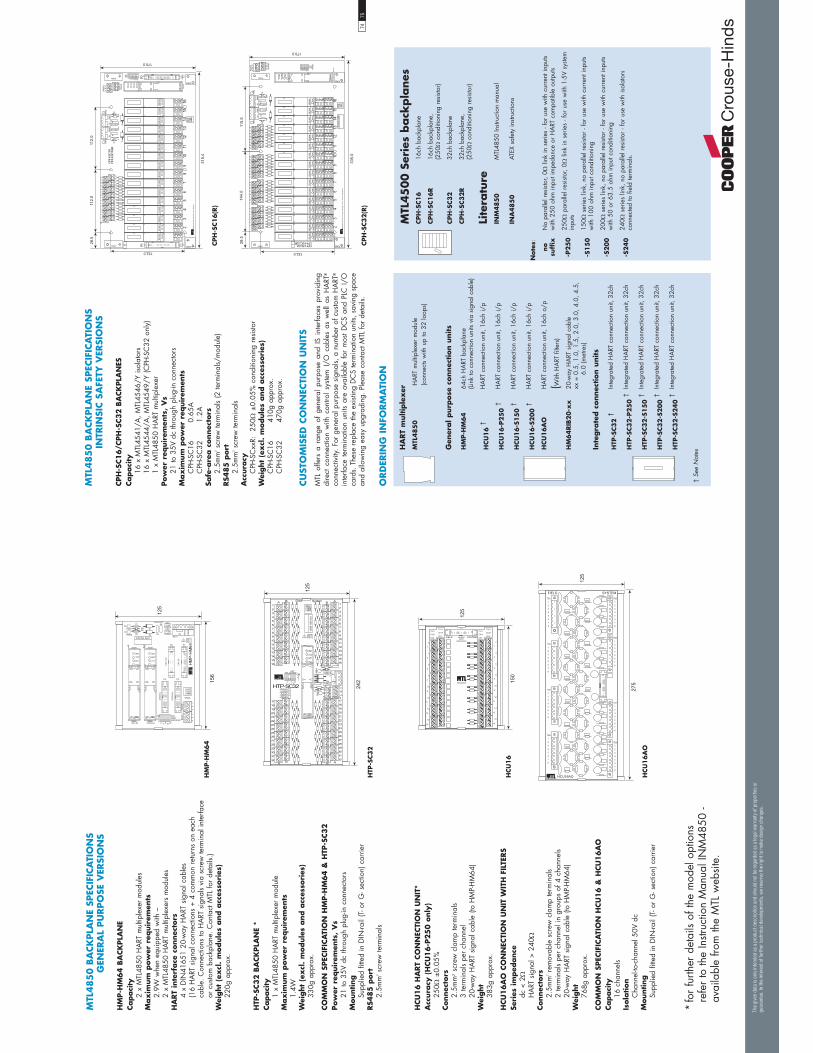
MTL
485
0 B
ACK
PLA
NE
SPEC
IFIC
ATI
ON
S G
ENER
AL
PU
RPO
SE V
ERSI
ON
S
HM
P-H
M64 B
ACK
PLA
NE
Capaci
ty2
x M
TL48
50 H
ART
mul
tiple
xer
mod
ules
Max
imum
pow
er r
equir
emen
ts2.
9W w
hen
equi
pped
with
–2
x M
TL48
50 H
ART
mul
tiple
xers
mod
ules
HA
RT
inte
rface
connec
tors
4 x
DIN
4165
1 20
-way
HA
RT s
igna
l cab
les
(16
HA
RT s
igna
l con
nect
ions
+ 4
com
mon
ret
urns
on
each
ca
ble.
Con
nect
ions
to H
ART
sig
nals
via
scre
w te
rmin
al in
terfa
ce
or c
usto
m b
ackp
lane
. Con
tact
MTL
for
deta
ils.)
Wei
ght
(ex
cl.
module
s and a
cces
sori
es)
220g
app
rox.
HTP
-SC32 B
ACK
PLA
NE
*Capaci
ty1
x M
TL48
50 H
ART
mul
tiple
xer
mod
ule
Max
imum
pow
er r
equir
emen
ts1.
4WW
eight
(ex
cl.
module
s and a
cces
sori
es)
330g
app
rox.
CO
MM
ON
SPEC
IFIC
ATI
ON
HM
P-H
M64 &
HTP
-SC32
Pow
er r
equir
emen
ts,
Vs
21 to
35V
dc
thro
ugh
plug
-in c
onne
ctor
sM
ounting
Supp
lied
fitte
d in
DIN
-rail
(T- o
r G
- sec
tion)
car
rier
RS4
85
port
2.5m
m2 s
crew
term
inal
s
HCU
16 H
ART
CO
NN
ECTI
ON
UN
IT*
Acc
ura
cy (
HCU
16-P
25
0 o
nly
)25
0 ±
0.05
%Connec
tors
2.5m
m2
scre
w c
lam
p te
rmin
als
3 te
rmin
als
per
chan
nel
20-w
ay H
ART
sig
nal c
able
(to
HM
P-H
M64
)W
eight
383g
app
rox.
HCU
16A
O C
ON
NEC
TIO
N U
NIT
WIT
H F
ILTE
RS
Seri
es im
ped
ance
dc <
2H
ART
sig
nal >
240
Connec
tors
2.5m
m2 r
emov
able
scr
ew c
lam
p te
rmin
als
2 te
rmin
als
per
chan
nel i
n gr
oups
of 4
cha
nnel
s20
-way
HA
RT s
igna
l cab
le (t
o H
MP-
HM
64)
Wei
ght
768g
app
rox.
CO
MM
ON
SPEC
IFIC
ATI
ON
HCU
16 &
HCU
16A
OCapaci
ty16
cha
nnel
sIs
ola
tion
Cha
nnel
-to-c
hann
el 5
0V d
cM
ounting
Supp
lied
fitte
d in
DIN
-rail
(T- o
r G
- sec
tion)
car
rier
* fo
r fu
rther
det
ails
of th
e m
odel
opt
ions
re
fer
to th
e In
struc
tion
Man
ual I
NM
4850
- av
aila
ble
from
the
MTL
web
site
.
!�
"#�$�%&�!!%'""
����������������
!�
!�!
%�
!�%�
!�
"(&��
)"�
)*"')"�
)*"'
%�
%�
�� +#%�
+#%�
����,�
����,�
-$�,�� -$��, �
-$�,�
-$��,��
-$��, �
-$��,��
+#%�
+#%�
����������
"."-�//���!'/&
!�&'-�!'0�1'0
$2+,$2 �
+� +�
+� +�
1�
1-
�
%"���
-
� �
%"��
���
%"��
��1
�/
��
���
���
���
&1� &1�
)�'0! "."&'2
�
�
�
�
�
�
�
&1
�
�
�
�
�
�
�
�
�
�
�
�
�
�
&1�
�
�
�
�
�
�
�
�
�
�
�
�
�
�
�
�
�
�
�
�
�
&1�
&1�
�
�
�
�
�
�
�
&1�
�
�
�
�
�
�
�
&1�
$-*� ��
���
���
77$2 �$�%&
�/&'%)�-'
&7�8
-9�8
-9�,-9�,
-9�8
&7�8
-9�,
-9�8
&7�8&7�8
-9�,
-9�8
$-*�
��
��
��
�
�
�
�
�
�
��
��
��
�
�
�
��
��
��
�
�
�
�
�
�
��
��
��
�
�
�
"."&'2)�'0!
+�
HM
P-H
M6
4
"34���)5��6
$&+,"-��
$�%&�!!%'"""#�
� � ��� � �
"."-�//�
�!'/&
!�&'-�!'0�1'0
%"���1%"����
-
1
�
� �11�
�
�
�
�
�
�
�
��
��
��
��
��
��
� �
�
�
�
�
�
�
�
�
��
��
��
��
��
��
�1
1 �
��
��
��
��
��
��
��
��
��
�
��
��
��
��
��
��
��
��
��
��
��
��
��
��
��
�
��
��
��
��
��
��
,+���,"���,"���,"���
�/ ��
+#%�
!�
%�
)"�)*"'
����,�
%�
%� )"�)*"'
����,�
!�
!�
%�
!
�+#%�
+#%�
-
1
�
���
���
HTP
-SC3
2
HCU
16
HCU
16
AO
7475
MTL
485
0 B
ACK
PLA
NE
SPEC
IFIC
ATI
ON
S IN
TRIN
SIC S
AFE
TY V
ERSI
ON
S
CPH
-SC16/C
PH
-SC32 B
ACK
PLA
NES
Capaci
ty16
x M
TL45
41/A
, MTL
4546
/Y is
olat
ors
16 x
MTL
4544
/A, M
TL45
49/Y
(CPH
-SC
32 o
nly)
1 x
MTL
4850
HA
RT m
ultip
lexe
rPow
er r
equir
emen
ts,
Vs
21 to
35V
dc
thro
ugh
plug
-in c
onne
ctor
sM
ax
imum
pow
er r
equir
emen
tsC
PH-S
C16
0.
65A
CPH
-SC
32
1.2A
Safe
-are
a c
onnec
tors
2.5m
m2 s
crew
term
inal
s (2
term
inal
s/m
odul
e)RS4
85
port
2.5m
m2 s
crew
term
inal
sA
ccura
cyC
PH-S
Cxx
R:
250
±0.
05%
con
ditio
ning
res
isto
rW
eight
(ex
cl.
module
s and a
cces
sori
es)
CPH
-SC
16
410g
app
rox.
CPH
-SC
32
470g
app
rox.
CU
STO
MIS
ED C
ON
NEC
TIO
N U
NIT
SM
TL o
ffers
a r
ange
of
gene
ral
purp
ose
and
IS i
nter
face
s pr
ovid
ing
dire
ct c
onne
ctio
n w
ith c
ontro
l sy
stem
I/O
cab
les
as w
ell
as H
ART
®
conn
ectiv
ity. F
or g
ener
al p
urpo
se s
igna
ls, a
num
ber
of c
usto
m H
ART
®
inte
rface
ter
min
atio
n un
its a
re a
vaila
ble
for
mos
t D
CS
and
PLC
I/O
ca
rds.
The
se re
plac
e th
e ex
istin
g D
CS
term
inat
ion
units
, sav
ing
spac
e an
d al
low
ing
easy
upg
radi
ng. P
leas
e co
ntac
t MTL
for
deta
ils.
2��4���
���&�9�����30�6�0����:'�����6
'%(��
-+$,"-�
-+$,"-� %
&"(��
��
��
�
�
��
��
�
�
���
���
����
����
��
���
����
����
��
!�&'
-�!'
0�1'
0
'%(��
&"(��
+#%�
+#%�
!�
!�
!
%�%�
)"�
)*"' ��,�
)"�
)*"' ��,�
%�%�
+#%�
����
+#%�
!�
2&0���� +#%
2&0���� +#%
2&0���� +#%
2&0���� +#%
2&0���� +#%
2&0���� +#%
2&0���� +#%
2&0���� +#%
2&0���� +#%
2&0��� +#%
2&0��� +#%
2&0��� +#%
2&0��� +#%
2&0��� +#%
2&0��� +#%
2&0��� +#%
2&0����
+#%
)�*0&
$�"&
$�%&
�1-
%"�
��1
%"���
��1-
"#�
$�%&
�!!%'""
� � � � � ��
$�%&
-9�����4
��,��
$�%&
-9�����4
�,�
�
��
��
�
��
���
� ��
����
����
+�+�
�����
�����
�����
����
�����
�����
�
'%(��
��
�
-+$,"-��
�
��
���
��
��
�
��
��
����
����
����
����
����
����
����
� ".
"-�/
/��!'/
&��
����
!�&'
-�!'
0�1'
0
����
'%(��
����
����
����
� ��
+#%�
+#%�
�1-
%"���1
%"����
�1-
2&0���� +#%
2&0���� +#%
2&0���� +#%
2&0���� +#%
2&0���� +#%
2&0���� +#%
2&0���� +#%
2&0���� +#%
2&0���� +#%
2&0���� +#%
2&0���� +#%
2&0���� +#%
2&0���� +#%
2&0���� +#%
2&0���� +#%
2&0���� +#%
!�
!�
!
%�%�
)"�
)*"' ��,�
)"�
)*"' ��,�
%�%�
+#%�
����
+#%�
"#�
$�%&
�!!%'""
� � � � � ��
-+$,"-��%
!�
-$�,��
&"(��
&"(��
2��4������&�9�����30�6�0����:'�����6
�����
����
�����
�����
�����
�����
CPH
-SC1
6(R
)
CPH
-SC3
2(R
)
HA
RT
multip
lex
er
MTL
48
50
HA
RT m
ultip
lexe
r m
odul
e (c
onne
cts
with
up
to 3
2 lo
ops)
Gen
eral purp
ose
connec
tion u
nits
HM
P-H
M6
464
ch H
ART
bac
kpla
ne(L
ink
to c
onne
ctio
n un
its v
ia s
igna
l cab
le)
HCU
16
†H
ART
con
nect
ion
unit,
16c
h i/
p
HCU
16
-P2
50
†H
ART
con
nect
ion
unit,
16c
h i/
p
HCU
16
-S1
50
†H
ART
con
nect
ion
unit,
16c
h i/
p
HCU
16
-S2
00
†H
ART
con
nect
ion
unit,
16c
h i/
p
HCU
16
AO
HA
RT c
onne
ctio
n un
it, 1
6ch
o/p
(With
HA
RT fi
lters
)
HM
64
RIB
20
-xx
20-w
ay H
ART
sig
nal c
able
xx =
0.5
, 1.0
, 1.5
, 2.0
, 3.0
, 4.0
, 4.5
, 6.
0 (m
etre
s)
Inte
gra
ted c
onnec
tion u
nits
HTP
-SC3
2 †
Inte
grat
ed H
ART
con
nect
ion
unit,
32c
h
HTP
-SC3
2-P
25
0 †
Inte
grat
ed H
ART
con
nect
ion
unit,
32c
h
HTP
-SC3
2-S
15
0 †
Inte
grat
ed H
ART
con
nect
ion
unit,
32c
h
HTP
-SC3
2-S
20
0 †
Inte
grat
ed H
ART
con
nect
ion
unit,
32c
h
HTP
-SC3
2-S
24
0 †
Inte
grat
ed H
ART
con
nect
ion
unit,
32c
h
† Se
e N
otes
ORD
ERIN
G I
NFO
RM
ATI
ON
MTL
45
00
Ser
ies
back
pla
nes
CPH
-SC1
616
ch b
ackp
lane
CPH
-SC1
6R
16ch
bac
kpla
ne,
(250
con
ditio
ning
res
isto
r)
CPH
-SC3
232
ch b
ackp
lane
CPH
-SC3
2R
32ch
bac
kpla
ne,
(250
con
ditio
ning
res
isto
r)
Lite
ratu
reIN
M4
85
0M
TL48
50 In
struc
tion
man
ual
INA
48
50
ATEX
saf
ety
instr
uctio
ns
Note
s:
no
suff
ixN
o pa
ralle
l res
isto
r, 0
link
in s
erie
s - f
or u
se w
ith c
urre
nt in
puts
with
250
ohm
inpu
t im
peda
nce
or H
ART
com
patib
le o
utpu
ts
-P2
50
250
par
alle
l res
isto
r, 0
link
in s
erie
s - f
or u
se w
ith 1
-5V
syste
m
inpu
ts
-S1
50
150
ser
ies
link,
no
para
llel r
esis
tor
- for
use
with
cur
rent
inpu
ts w
ith 1
00 o
hm in
put c
ondi
tioni
ng
-S2
00
200
ser
ies
link,
no
para
llel r
esis
tor
- for
use
with
cur
rent
inpu
ts w
ith 5
0 or
63.
5 oh
m in
put c
ondi
tioni
ng
-S2
40
240
ser
ies
link,
no
para
llel r
esis
tor
- for
use
with
isol
ator
s co
nnec
ted
to fi
eld
term
inal
s.
The
giv
en d
ata
is o
nly
inte
nded
as
a pro
duct
des
crip
tion
and
shou
ld n
ot b
e re
gar
ded
as
a le
gal
war
ranty
of pro
per
ties
or
guar
ante
e. In
the
inte
rest
of
furt
her
tec
hnic
al d
evel
opm
ents
, w
e re
serv
e th
e ri
ght
to m
ake
des
ign
chan
ges
.

Com
munic
ate
with,
confi
gure
and m
onitor
HA
RT®
sm
art
dev
ices
in
safe
and h
aza
rdous
are
as
MTL
4840
Ser
ies
The
MTL
48
40
H
AR
T®
connec
tion
syst
em
prov
ides
a s
impl
e in
terfa
ce b
etw
een
smar
t de
vice
s in
th
e fie
ld
and
HA
RT®
in
strum
ent
man
agem
ent
softw
are
run
on a
PC
.
The
syst
em i
s base
d o
n 1
6-ch
anne
l mod
ular
ity
to
prov
ide
a co
mpa
ct,
easi
ly
conf
igur
able
an
d ex
pand
able
sy
stem
. Usi
ng a
sta
ndar
d RS
485
seria
l lin
k, u
p to
793
6 in
divi
dual
HA
RT®
dev
ices
can
be
conn
ecte
d to
a s
ingl
e w
orks
tatio
n.
For
the
optim
um s
olut
ion,
cho
ose
from
a r
ange
of
gene
ral
purp
ose
and
IS
term
inat
ion
boar
ds.
For
max
imum
flex
ibili
ty th
e BP
HM
64 H
ART
® b
ackp
lane
lo
cate
s an
MTL
4841
com
mun
icat
ions
mod
ule
and
up t
o fo
ur M
TL48
42 i
nter
face
mod
ules
. G
ener
al
purp
ose
HA
RT®
con
nect
ion
units
and
IS b
ackp
lane
s ar
e al
so a
vaila
ble,
eac
h fit
ted
with
an
inte
rface
cab
le
for
conn
ectio
n to
the
BPH
M64
HA
RT®
bac
kpla
ne.
MTL
4841
an
d M
TL48
42
mod
ules
ca
n al
so
be
loca
ted
on H
MU
16 t
erm
inat
ion
boar
ds f
or g
ener
al
purp
ose
appl
icat
ions
or
on B
PMH
16 /
BPM
H16
U
/ BP
SH16
/ B
PSH
16-3
2 ba
ckpl
anes
for
IS
isol
ator
re
quire
men
ts.
The
DIN
-ra
il
mo
un
tin
g
HC
U16
an
d H
CU
16A
OH
ART
® c
onne
ct t
o 16
gen
eral
pur
pose
fie
ld
inst
rum
ents
w
hile
m
aint
aini
ng
chan
nel
to
chan
nel
isol
atio
n. R
esis
tor
cond
ition
ing
optio
ns a
re
com
patib
le w
ith a
ll I/
O c
ards
. It a
llow
s pa
ss-th
roug
h co
nnec
tions
for t
rans
mitt
er p
ower
sup
ply,
inpu
t sig
nal
and
com
mon
.
The
HCU
16A
O u
nit i
nclu
des
HA
RT®
filt
ers
for
I/O
car
ds in
com
patib
le w
ith H
ART
® s
igna
ls.
BP
MH
16
/BP
MH
16
U/B
PSH
16
/BP
SH
16
-32
back
plan
es w
ith M
TL48
40 H
ART
® m
odul
es f
itted
, co
nnec
t eith
er 1
6 or
32
IS fi
eld
instr
umen
ts. A
dapt
er
card
s ar
e av
aila
ble
for
the
BPM
H16
U
for
easy
in
tegr
atio
n to
I/O
car
ds a
nd u
sers
hav
e a
choi
ce o
f a
DIN
-rail
mou
ntin
g op
tion.
Num
erous
featu
res
may
be
in
clud
ed
in
the
conn
ectio
n un
its
and
back
plan
es,
as
requ
ired.
C
hann
el
to
chan
nel
isol
atio
n;
resi
stor
s w
here
re
quire
d fo
r HA
RT®
sig
nal c
ondi
tioni
ng; a
nd H
ART
®
filte
rs f
or a
nalo
gue
syste
ms
whe
re t
he o
utpu
t si
gnal
in
terfe
res
with
HA
RT®
dat
a or
bec
omes
uns
tabl
e w
ith th
e pr
esen
ce o
f the
HA
RT®
sig
nal.
Cust
om
ised
b
ack
pla
nes
a
nd
co
nnec
tion
units
are
avai
labl
e to
pro
vide
dire
ct c
onne
ctio
n fro
m
DC
S I/
O
cabl
es,
repl
acin
g th
e st
anda
rd
term
inat
ion
boar
d.
MTL
HA
RT
multip
lex
ers
are
certi
fied
by B
ASE
EFA
as
a s
afet
y re
late
d su
b-sy
stem
to IE
C61
508.
See
the
SR S
erie
s In
terfa
ces
sect
ion
of th
is c
atal
ogue
.
•
Com
pact
, id
eal fo
r new
pro
ject
s and u
pgra
des
•
Channel
to c
hannel
iso
lation
option
•
HA
RT
signal co
nditio
nin
g
•
SIL3
rating
•
Connec
t up t
o 7
936 loops
to a
si
ngle
PC
•
LED
indic
ation o
f lo
op b
eing
scanned
•
Easi
ly s
cala
ble
modula
r sy
stem
7677
MT
L48
40 S
ER
IES
SYST
EM
DIA
GR
AM
Haza
rdous
Are
aSa
feA
rea
@3�.���%� ������
�%�8��8�
��
�&
��
�&
��
�&
��
�&
��
�&
��
�&
.����� �9.��(���� �%������%� ������
9.��(��
�� �%������%�
������
�
�
� A��$9.��(��$�%���������&9.��(��
@3�.�%��� ���� ������
��
�&
@3�.
@3�.
@3�.
@3�.
A��$9.��(��$�%���������&@3�.
���%� ��������8��8��������%���
9.��(��
@3�.
�%�������
������
@3�.
�=� 3
��/%���
I���������%�1
��%%�%/�%���� �%�
�%�/� �%�����!���
>���') &@3�.
J��8����
�+� �=�(�
��%8�����
�+�(�
� ��
�9.���&�
9.����
2 �&
��
.�� �%��
.�� �%��
�
�
���������%����
�"��� �/�1+7��1
The
giv
en d
ata
is o
nly
inte
nded
as
a pro
duct
des
crip
tion
and
shou
ld n
ot b
e re
gar
ded
as
a le
gal
war
ranty
of pro
per
ties
or
guar
ante
e. In
the
inte
rest
of
furt
her
tec
hnic
al d
evel
opm
ents
, w
e re
serv
e th
e ri
ght
to m
ake
des
ign
chan
ges
.

MT
L48
40 S
ER
IES
MO
DU
LE
SP
EC
IFIC
ATIO
NS
MTL
4841 C
OM
MU
NIC
ATI
ON
S M
OD
ULE
Host
syst
em inte
rface
RS48
5 2-
wire
mul
tidro
pUp
to 3
1 M
TL48
41 m
odule
s can
be
conn
ecte
d to
one
hos
t sta
tion
Uni
t add
ress
: s
witc
h-se
lect
able
on
top
of m
odul
eIs
ola
tion
RS48
5 ou
tput
isol
ated
from
bac
kpla
ne p
ower
sup
ply
Seri
al co
mm
unic
ation p
ara
met
ers
RS48
5 Ba
ud r
ate:
1.
2, 9
.6, 1
9.2,
38.
4kba
ud, s
witc
h-
se
lect
able
on
top
of m
odul
eRS
485
high
way
leng
th:
up to
1km
MTL
syst
em inte
rface
Links
with
up
to 1
6 M
TL48
42 H
ART
® in
terfa
ce m
odul
es v
ia
inte
rface
bus
on
back
plan
e/rib
bon
cabl
eLE
D indic
ato
rsG
reen
: one
pro
vide
d fo
r po
wer
and
sta
tus
indi
catio
nPow
er r
equir
emen
tsPo
wer
ed fr
om b
ackp
lane
Pow
er c
onsu
mpt
ion
<1.0
WIn
stru
men
t m
anagem
ent
soft
ware
support
edSe
e 'In
strum
ent m
anag
emen
t sof
twar
e'
MTL
4842 H
ART®
IN
TERFA
CE
MO
DU
LEM
TL s
yst
ems
inte
rface
Links
up
to 1
6 lo
ops
via
back
plan
esRe
ceiv
es m
ultip
lexe
r co
ntro
l sig
nals
via
inte
rface
bus
from
M
TL48
41 a
nd s
elec
ts on
e ch
anne
l for
com
mun
icat
ion
Unit a
ddre
ssSw
itch
sele
ctab
le o
n to
p of
mod
ule
Inte
rface
bus
Tota
l len
gth
of in
terfa
ce b
us b
etw
een
mod
ule
1 an
d m
odul
e 16
m
ust n
ot e
xcee
d 4m
LED
indic
ato
rsG
reen
: on
e pr
ovid
ed fo
r po
wer
Am
ber:
one
to in
dica
te u
nit i
s se
lect
ed b
y M
TL48
41Re
d:
fo
ur to
iden
tify
loop
add
ress
Pow
er r
equir
emen
tsPo
wer
ed fr
om b
ackp
lane
Pow
er c
onsu
mption
<0.1
W
MTL
4000 S
ERIE
S M
OD
ULE
S(S
ee
'MTL
40
00
Se
ries
' fo
r det
aile
d
spec
ific
ations
and
circ
uit d
iagra
ms)
MTL
40
41
A:
C
urre
nt r
epea
ter,
4/20
mA
, pas
sive
inpu
t for
sm
art
trans
mitt
ers
MTL
40
41
B:
Re
peat
er p
ower
sup
ply,
4/2
0mA
, fo
r 2-
or
3-w
ire
trans
mitt
ers
MTL
40
41
P:
Hig
h po
wer
rep
eate
r po
wer
sup
ply,
4/2
0mA
, fo
r 2-
or
3-w
ire tr
ansm
itter
s
MTL
40
44
: Re
peat
er p
ower
sup
ply,
4/2
0mA
, tw
o ch
anne
l, fo
r 2
wire
tran
smitt
ers
MTL
40
46
/C:
Isola
ting
driv
er, f
or H
ART
® v
alve
pos
ition
ers
MTL
40
46
P:
Hig
h po
wer
isol
atin
g dr
iver f
or H
ART®
val
ve p
ositio
ners
CO
MM
ON
SPEC
IFIC
ATI
ON
(applie
s to
all
MTL
48
40
and 4
00
0 S
erie
s m
odule
s)
Loca
tion o
f units
Safe
are
a (M
TL48
40 c
an b
e lo
cate
d in
Div
2)Lo
ng-t
erm
dri
ftN
o re
calib
ratio
n ne
cess
ary
Am
bie
nt
tem
per
atu
re lim
its
–20
to +
60°C
con
tinuo
us w
orki
ng–4
0 to
+80
°C s
tora
geH
um
idity
5 to
95%
RH
(non
-con
dens
ing)
Mounting
On
surfa
ce o
r D
IN-ra
il m
ount
ed M
TL o
r cu
stom
bac
kpla
nes.
M
ount
ing
pitc
h 16
mm
Wei
ght
100g
app
roxi
mat
ely
Pow
erH
ART
sign
als
MTL
4842
cont
rol
sign
als
RS48
5Po
wer
Sele
ctio
nlo
gic
Mod
em
Mic
ropr
oces
sor
Con
figur
atio
nsw
itche
sW
'dog
Mem
ory
1–16
10495
89
15.8
MTL
48
41
com
munic
ations
module
MTL
48
42
HA
RT®
inte
rface
module
DIM
ENSI
ON
S (M
M)
7879
MT
L484
0 SE
RIE
S B
ACK
PLA
NES
SP
ECIF
ICAT
ION
SG
ENER
AL
PUR
POSE
VER
SIO
NS
DIM
ENSI
ON
S (M
M)
���
���
&1�&1�
)�'0!"."&'2
�
�
�
�
�
�
�
&1
�
�
�
�
�
�
�
�
�
�
�
�
�
�
&1�
�
�
�
�
�
�
�
�
�
�
�
�
�
�
�
�
�
�
�
�
�
&1�
&1�
�
�
�
�
�
�
�
&1�
�
�
�
�
�
�
�
&1�
$-*� ��
BPH
M64 B
ACK
PLA
NE
Capaci
ty1
x M
TL48
41 c
omm
unic
atio
ns m
odul
e4
x M
TL48
42 H
ART
® in
terfa
ce m
odul
esN
B: A
n M
TL48
41 m
odul
e is
nee
ded
for
only
one
in e
very
si
xtee
n M
TL48
42 m
odul
esM
ax
imum
pow
er r
equir
emen
ts1.
35W
whe
n eq
uipp
ed w
ith:–
1 x
MTL
4841
com
mun
icat
ions
mod
ule
4 x
MTL
4842
HA
RT®
inte
rface
mod
ules
HA
RT
inte
rface
connec
tors
4 x
DIN
4165
1 20
-way
rib
bon
cabl
es(1
6 H
ART
® s
igna
l con
nect
ions
+ 4
com
mon
ret
urns
on
each
ca
ble.
Con
nect
ions
to H
ART
® s
igna
ls vi
a sc
rew
term
inal
in
terfa
ce o
r cu
stom
bac
kpla
ne. C
onta
ct M
TL fo
r de
tails
.)W
eight
(ex
cl.
module
s and a
cces
sori
es)
29
6g a
ppro
x.
HM
U16/3
2Capaci
ty
1 x
MTL
4841
com
mun
icat
ions
mod
ule
2
x M
TL48
42 in
terfa
ce m
odul
es
Pow
er r
equir
emen
ts,
Vs
21
to 3
5V d
c th
roug
h pl
ug in
con
nect
ors
Max
imum
pow
er r
equir
emen
ts
1.2W
w
hen
fully
pop
ulat
edIn
terf
ace
bus
connec
tors
10
-way
rib
bon
sock
etRS4
85
port
2.
5mm
2 sc
rew
term
inal
sM
ounting
Su
pplie
d fit
ted
with
DIN
-rail
(T-o
r G
-sect
ion)
Wei
ght
(exc
l. m
odul
es a
nd a
cces
sorie
s)
330g
CO
MM
ON
SPEC
IFIC
ATI
ON
BPH
M64 &
HM
U16
Pow
er r
equir
emen
ts,
Vs
21
to 3
5V d
c th
roug
h pl
ug-in
con
nect
ors
Mounting
Su
pplie
d fit
ted
with
DIN
-rail
(T- o
r G
- sec
tion)
car
rier
Inte
rface
bus
connec
tor
10
-way
rib
bon
sock
etRS4
85
port
2.
5mm
2 sc
rew
term
inal
s
HCU
16 H
ART®
CO
NN
ECTI
ON
UN
ITA
ccura
cy (
HCU
16
-P2
50
only
)
250
±0.
05%
Connec
tors
2.
5mm
2 sc
rew
cla
mp
term
inal
s
3 te
rmin
als
per
chan
nel
20
-way
flat
cab
le (t
o BP
HM
64)
Wei
ght
38
3g
HCU
16A
O
HA
RT®
CO
NN
ECTI
ON
U
NIT
W
ITH
FI
LTER
SSe
ries
im
ped
ance
dc
<2
HA
RT® s
igna
l >24
0Connec
tors
2.
5mm
2 re
mov
able
scr
ew c
lam
p te
rmin
als
2
term
inal
s pe
r ch
anne
l in
grou
ps o
f 4 c
hann
els
20
-way
flat
cab
le (t
o BP
HM
64)
Wei
ght
76
8g
COM
MO
N S
PECI
FICA
TIO
N H
CU16 &
HCU
16A
OCapaci
ty
16 c
hann
els
Isola
tion
C
hann
el to
cha
nnel
50V
dc
Mounting
Su
pplie
d fit
ted
with
DIN
-rail
(T- o
r G
- sec
tion)
car
rier
���
�� 2&0����2&0����2&0����2&0����2&0����
+#%�
+#%�+�+�+�+�
+�%&�+�%&�
+
+�
�������
+#%�������
)"�
2&0�
���
2&0�
���
%"��
�%"��
�
-�//�
2&0����
���
���
+�#'%
�1
-�
1-
+� +�
��
��
��
�
�
�
�
�
�
��
��
��
�
�
�
��
��
��
�
�
�
�
�
�
��
��
��
�
�
�
)�'0! 1+$2 �$�%&
�/&'%)�-'
"."&'2
&7�8
-9�8
-9�,-9�,
-9�8
&7�8
-9�,
-9�8
&7�8&7�8
-9�,
-9�8
$-*�
HM
U1
6A
I
HCU
16
AO
&7�8
-9�8
-9�,-9�,
-9�8
&7�8
-9�,
-9�8
&7�8&7�8
-9�,
-9�8
$-*�
)�'0!
+�
1+$2 �$�%&
�/&'%)�-'
"."&'2
��
��
��
�
�
�
�
�
�
��
��
��
�
�
�
��
��
��
�
�
�
�
�
�
��
��
��
�
�
�
���
���
HCU
16
BPH
M6
4
The
giv
en d
ata
is o
nly
inte
nded
as
a pro
duct
des
crip
tion
and
shou
ld n
ot b
e re
gar
ded
as
a le
gal
war
ranty
of pro
per
ties
or
guar
ante
e. In
the
inte
rest
of
furt
her
tec
hnic
al d
evel
opm
ents
, w
e re
serv
e th
e ri
ght
to m
ake
des
ign
chan
ges
.
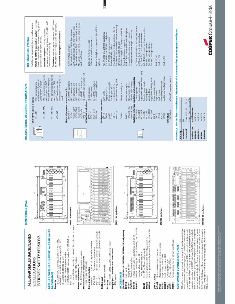
MT
L484
0 SE
RIE
S B
ACK
PLA
NES
SPEC
IFIC
ATIO
NS
INT
RIN
SIC
SA
FET
Y V
ERSI
ON
S
BP
MH
16
/B
PM
H1
6U
/B
PS
H1
6/B
PS
H1
6-3
2
BA
CK
PLA
NES
Capaci
ty
16 x
MTL
4041
A, M
TL40
41B,
MTL
4041
P, M
TL40
46,
MTL
4046
C, M
TL40
46P
isol
ator
s (e
xcep
t BPS
H16
-32)
16
x M
TL40
44 (B
PSH
16-3
2 on
ly)
1
x M
TL48
41 c
omm
unic
atio
ns m
odul
e
1 x
MTL
4842
HA
RT® in
terfa
ce m
odul
e (2
x M
TL48
42 o
n
BPSH
16-3
2)
NB:
A
n M
TL48
41
mod
ule
is
need
ed
for
only
on
e in
ev
ery
sixt
een
MTL
4842
mod
ules
Pow
er r
equir
emen
ts,
Vs
21
to 3
5V d
c th
roug
h pl
ug-in
con
nect
ors
Max
imum
pow
er r
equir
emen
ts
1.35
A (1
.55A
BPS
H16
-32)
Sa
fe-a
rea c
onnec
tors
BP
MH
16:
Elco
801
6 38
-pin
mal
e co
nnec
tor
BP
MH
16U
: To
cus
tom
er's
req
uire
men
ts
BPSH
16:
2.5m
m2
scre
w te
rmin
als
(2 te
rmin
als/
mod
ule)
BP
SH16
-32:
2.
5mm
2 sc
rew
term
inal
s (4
term
inal
s/m
odul
e)RS4
85
port
2.
5mm
2 sc
rew
term
inal
sA
ccura
cy
BPSH
16-3
2R:
250
±0.
05%
con
ditio
ning
res
isto
rW
eight
(ex
cl.
module
s and a
cces
sori
es)
35
0g a
ppro
x.
ACCES
SORIE
S(f
or B
PMH
16/B
PMH
16U
/BPS
H16/B
PSH
16-3
2 b
ack
pla
nes)
ERK
18
Ea
rth r
ail k
itTS
K18
Ta
ggin
g str
ip k
itV
MPH
16
Verti
cal m
ount
ing
plat
eSM
S01
Su
rface
mou
ntin
g ki
t for
bac
kpla
nes,
pac
k of
40
DM
K01
D
IN-ra
il m
ount
ing
kit
(T-
or
G-se
ctio
n)
for
VMPH
16
mou
ntin
g pl
ate,
pac
k of
40
16-w
ay b
ackp
lane
s re
quire
6EL
C38
El
co 8
016,
38-
way
cab
le p
lug
kit
FUS0
2
Fuse
kit,
pro
tect
s M
TL48
41/4
842,
pac
k of
10
FUS1
6
Fuse
kit,
pro
tect
s m
odul
e po
sitio
ns 1
to 1
6, p
ack
of 1
0
(for
MTL
4000)
CCH
01
H
azar
dous
-are
a cr
imp
conn
ecto
r SC
C01
H
azar
dous
-are
a sc
rew
-cla
mp
conn
ecto
rCRC01
La
rge
crim
ps, p
ack
of 1
00CRC02
Sm
all c
rimps
, pac
k of
100
CRT0
1
Crim
p to
ol fo
r C
RC01
CRT0
2
Crim
p to
ol fo
r C
RC02
CRR01
C
rimp
rem
oval
tool
for
CRC
01 a
nd C
RC02
�� ��&
���
'()������ �����&
�(4�
�)
2�9@�&
� �
�'
���
��
2&0�
���
2&0�
���
2&0�
���
2&0�
���
2&0�
���
2&0�
���
2&0�
���
2&0�
���
2&0�
���
2&0�
���
2&0�
���
2&0�
���
2&0�
���
2&0�
���
2&0�
���
2&0�
���
2&0�
���
2&0�
���
1*"�������1*"�1
%"�����
��
�
�
!�
+#%�
1+2$� *
!�
!�
!
&"(��
)*"'
)*"'
+#%�
!�
%�
%�
)"�
)"�
"(&��
%0�
!�
"(&��
����
+#%�
+#%�
%0�2�/
+#%�
"(&��
���
����
��
2��4�������&�9�����3�0�6�0������'�����6
���
��
&"(��
"."-�//���!'/&
��1�-�����1�-
����
����
!�&'
-�!'
0�1'0
%"����1
��
�
+#%�
2�/
+�
+�
���)
���
��
���
�� ��&
���
'()������ �����&
�(4�
�)
2�+@�&
� �
�'
���
��
� �
���
��&
�(4�
�
�'
�)
� ��
����
����
����
����
����
��
��
1+"$� ,��
�
��
���
2&0����
2&0����
2&0����
2&0����
2&0����
2&0����
2&0����
2&0����
2&0����
2&0����
2&0����
2&0����
2&0����
2&0�
���
2&0����
2&0����
2&0����
2&0����
2&0����
����
����
����
� ��
����
����
����
����
��
����
����
����
��
��
�
��
DIM
ENSI
ON
S (M
M)
BPM
H1
6 b
ack
pla
ne
BPM
H1
6U
back
pla
ne
BPSH
16
back
pla
ne
BPSH
16
-32
back
pla
ne
CU
STO
MIS
ED C
ON
NEC
TIO
N U
NIT
SM
TL o
ffers
a r
ange
of
gene
ral p
urpo
se a
nd IS
inte
rface
s pr
ovid
ing
dire
ct c
onne
ctio
n w
ith c
ontro
l sys
tem
I/O
cab
les
as w
ell a
s H
ART
®
conn
ectiv
ity.
For
IS a
pplic
atio
ns,
MTL
's u
nive
rsal
bac
kpla
nes,
with
a
cust
omis
ed a
dapt
er c
ard,
giv
e th
e us
er a
com
patib
le s
yste
m
conn
ecto
r co
mpl
ete
with
HA
RT® in
terfa
ce. B
PMH
16U
(see
ove
rleaf
), BP
M16
U a
nd B
PM32
(se
e 'S
yste
m In
tegr
atio
n' s
ectio
n) b
ackp
lane
s m
ay b
e us
ed f
or I
S si
gnal
s. F
or g
ener
al p
urpo
se s
igna
ls, a
ran
ge
of c
usto
m H
ART
® i
nter
face
ter
min
atio
n un
its a
re a
vaila
ble
for
mos
t D
CS
and
PLC
I/O
car
ds. T
hese
repl
ace
the
exis
ting
DC
S te
rmin
atio
n un
its,
savi
ng s
pace
and
allo
win
g ea
sy u
pgra
ding
. Pl
ease
con
tact
M
TL fo
r de
tails
.
8081
MTL
4840 S
erie
s m
odule
sM
TL48
41
HA
RT c
omm
unic
atio
ns
mod
ule
pre-
conf
igur
ed fo
r C
orne
rsto
ne™
pro
toco
lM
TL48
41-A
MS
HA
RT c
omm
unic
atio
ns m
odul
e pr
e-co
nfig
ured
for
AM
S In
telli
gent
Dev
ice
Man
ager
MTL
4841
-PRM
H
ART
com
mun
icat
ions
mod
ule
pre-
conf
igur
ed fo
r PR
MM
TL48
42
HA
RT in
terfa
ce m
odul
e (c
omm
unic
ates
with
up
to 1
6 lo
ops)
THE
CO
MPLE
TE S
YST
EMTh
e fo
llow
ing
com
pone
nts
form
a c
ompl
ete
syste
m:
MTL
4840 H
ART®
connec
tion s
yst
em –
pro
vide
s si
mpl
e co
nnec
tion
to fi
eld
instr
umen
ts, u
sing
gen
eral
pu
rpos
e an
d IS
term
inat
ion
boar
ds.
Per
sonal co
mpute
r –
runn
ing
instr
umen
t m
anag
emen
t sof
twar
e an
d lin
ked
to M
TL48
41 H
ART
co
mm
unic
atio
ns m
odul
es b
y:
Conve
rter
– c
onne
ctin
g th
e co
mpu
ter’s
RS2
32 p
ort t
o th
e M
TL48
40 S
erie
s' b
ackp
lane
RS4
85 c
onne
ctor
.
Inst
rum
ent
managem
ent
soft
ware
Gen
eral purp
ose
connec
tion u
nits
BP
HM
64
64 c
h H
ART
bac
kpla
ne
HA
RT in
terfa
ce c
onne
ctor
H
CU
16
HA
RT c
onne
ctio
n un
it N
o pa
ralle
l res
isto
r, 0
link
fitte
d in
ser
ies
H
CU
16-P
250
HA
RT c
onne
ctio
n un
it 25
0 p
aral
lel r
esis
tor,
0 li
nk fi
tted
in s
erie
s
HC
U16
-S20
0 H
ART
con
nect
ion
unit
No
para
llel r
esis
tor,
200
res
isto
r fit
ted
in s
erie
s
HC
U16
-S15
0 H
ART
con
nect
ion
unit
No
para
llel r
esis
tor,
150
res
isto
r fit
ted
in s
erie
s
HC
U16
AO
16
ch
HA
RT c
onne
ctio
n un
it W
ith H
ART
filte
rs
HM
U16
16
ch
HA
RT c
omm
unic
atio
n un
it M
TL4000 b
ack
pla
nes
BP
MH
16
16 c
h ba
ckpl
ane
Safe
-are
a m
ultiw
ay c
onne
ctor
BP
SH16
16
ch
back
plan
e Sa
fe-a
rea
scre
w-c
lam
p co
nnec
tor
BP
SH16
-32
32 c
h H
ART
bac
kpla
ne
BPM
H16
U
16 c
h H
ART
bac
kpla
ne
Requ
ires
back
plan
e ad
apte
r ca
rd (c
all M
TL fo
r
optio
ns)
Back
pla
ne
acc
esso
ries
ER
K18
Earth
rai
l kit
For
BPM
H16
and
BPS
H16
bac
kpla
nes
TS
K18
Tagg
ing
strip
kit
For
BPM
H16
and
BPS
H16
bac
kpla
nes
EL
C38
38
-way
Elc
o co
nnec
tor
For
BPM
H16
saf
e-ar
ea c
onne
ctio
n
FUS0
2 Fu
se k
it, p
ack
of 1
0 Pr
otec
ts M
TL48
41/4
842
FU
S16
Fuse
kit,
pac
k of
10
Prot
ects
back
plan
e m
odul
e po
sitio
ns 1
to 1
6
VMPH
16
Back
plan
e m
ount
ing
plat
e Fo
r D
IN-ra
il an
d no
n-m
etal
lic s
urfa
ce m
ount
ing
(B
PMH
16 a
nd B
PSH
16 o
nly)
D
MK0
1 D
IN-ra
il m
ount
ing
kit
DIN
-rail
mou
ntin
g kit
, T- o
r G-se
ction
(pac
k of
40)
16
-way
bac
kpla
nes
requ
ire 6
SM
S01
Surfa
ce m
ount
ing
kit
Pack
of 4
0 - 4
req
uire
d fo
r ea
ch b
ackp
lane
H
M64
RIB1
0-xx
Ri
bbon
Cab
le
10-w
ay
-xx
spec
ifies
the
cabl
e le
ngth
- m
ax 4
m
HM
64RI
B20-
xx
Ribb
on C
able
20
-way
-x
x sp
ecifi
es th
e ca
ble
leng
th -
max
4.5
mIs
ola
ting inte
rface
module
s and a
cces
sori
es
MTL
4041
A
Cur
rent
rep
eate
r 4/
20m
A, p
assi
ve in
put,
for
smar
t tra
nsm
itter
s
MTL
4041
B Re
peat
er p
ower
sup
ply
4/20
mA
, for
2- o
r 3-
wire
tran
smitt
ers
M
TL40
41P
Hig
h po
wer
rep
eate
r po
wer
sup
ply
4/20
mA
, for
2- o
r 3-
wire
tran
smitt
ers
M
TL40
44
Repe
ater
pow
er s
uppl
y 2c
h, 4
/20m
A, s
mar
t, fo
r 2-
wire
tran
smitt
ers
M
TL40
46
Isola
ting
driv
er
For
HA
RT v
alve
pos
ition
ers
M
TL40
46C
Iso
latin
g dr
iver
Fo
r H
ART
val
ve p
ositi
oner
s
MTL
4046
P H
igh
pow
er is
olat
ing
driv
er
For
HA
RT v
alve
pos
ition
ers
C
CH
01
Crim
p co
nnec
tor
head
er
CRC
01
Larg
e cr
imps
Pa
ck o
f 100
C
RC02
Sm
all c
rimps
Pa
ck o
f 100
SC
C01
Sc
rew
-cla
mp
conn
ecto
r
MPL
01
Mod
ule
posi
tion
labe
l, bl
ank
Pack
of 5
0
Lite
ratu
re
INM
4840
M
TL48
40 in
struc
tion
man
ual
Countr
y
US
Auth
ori
ty
FMSt
andard
C
lass
360
0, 3
611,
381
0
C
lass
1, D
iv 2
, Gps
ABC
DPro
duct
No.
Cer
tifi
cate
No.
MTL
4841
30
0914
9M
TL4842
30
0914
9H
CU
16
30
0914
9BPM
H64
30
0914
9
MTL
48
40
SER
IES
ORD
ERIN
G I
NFO
RM
ATI
ON
HARTA
PPRO
VA
LS -
for
the
late
st c
ertifi
cation info
rmation v
isit w
ww
.mtl-i
nst
.com
/support
/cer
tifi
cate
s
The
giv
en d
ata
is o
nly
inte
nded
as
a pro
duct
des
crip
tion
and
shou
ld n
ot b
e re
gar
ded
as
a le
gal
war
ranty
of pro
per
ties
or
guar
ante
e. In
the
inte
rest
of
furt
her
tec
hnic
al d
evel
opm
ents
, w
e re
serv
e th
e ri
ght
to m
ake
des
ign
chan
ges
.

Zene
r Ba
rrie
rs
Our
ran
ge o
f sh
unt-
diod
e sa
fety
bar
riers
are
the
sim
ples
t ty
pe o
f IS
int
erfa
ce f
or p
rote
ctin
g el
ectr
ical
circ
uits
in
haza
rdou
s ar
eas.
The
com
pact
and
inex
pens
ive
units
are
mou
nted
and
ear
thed
in o
ne o
pera
tion,
ens
urin
g th
e sa
fest
po
ssib
le in
stal
latio
n w
ith u
ltra-
high
rel
iabi
lity.
The
MTL
7700
Ser
ies
has
an im
pres
sive
ped
igre
e an
d th
e us
er w
ill b
enef
it fr
om th
e ex
cept
iona
l app
licat
ion
know
ledg
e th
at M
TL h
as d
evel
oped
in th
is fi
eld.
Not
e th
at th
e w
ell k
now
n M
TL70
0 Se
ries
of b
usba
r m
ount
ed s
afet
y ba
rrie
rs c
ontin
ues
to b
e av
aila
ble.
For
det
ails
and
sp
ecifi
catio
n sh
eets
ple
ase
visi
t our
web
site
at h
ttp://
ww
w.m
tl-in
st.c
om
DIN
rail
mounting
safe
ty b
arr
iers
MTL
7700
SER
IES
Since
its
intr
oduct
ion
in
1984
the
MTL
700
Serie
s ba
rrie
r has
esta
blis
hed
itsel
f as
the
wor
ldw
ide
stand
ard
for
safe
ty b
arrie
rs.
Know
n fo
r its
qua
lity
and
relia
bilit
y, th
e M
TL70
0 Se
ries
is w
idel
y us
ed i
n ap
plic
atio
ns a
ll ov
er th
e w
orld
.
The
MTL
7700
Seri
es
follo
ws
clos
ely
in
the
foot
steps
of t
he M
TL70
0, b
ut a
s a
DIN
rai
l mou
ntin
g ba
rrie
r, pr
ovid
ing
quic
k an
d ea
sy in
stalla
tion
with
out
the
need
for
spec
ial h
ardw
are.
Rem
ova
ble
te
rmin
als
are
use
d f
or e
ase
of
insta
llatio
n, m
aint
enan
ce a
nd f
or p
rovi
ding
a l
oop
disc
onne
ct b
y si
mpl
y un
plug
ging
the
term
inal
s fro
m
the
side
of t
he m
odul
e. W
ire e
ntry
is a
lso a
ngle
d to
as
sist
wiri
ng w
ithin
lim
ited
spac
e en
clos
ures
.
MTL
7700 b
arr
iers
cla
mp s
imply
and
sec
urel
y on
to
stand
ard
T-sec
tion
DIN
ra
il,
sim
ulta
neou
sly
mak
ing
a re
liabl
e IS
ear
th c
onne
ctio
n.
For
applic
ations
wher
e fi
eld p
ow
er is
requ
ired
for s
witc
h in
puts
or 2
-wire
tran
smitt
ers,
the
MTL
7700
Se
ries
prov
ides
a b
usse
d po
wer
feed
faci
lity.
Whe
n us
ed i
n co
njun
ctio
n w
ith t
he M
TL77
98 p
ower
fee
d m
odul
e th
e us
er h
as a
ful
ly p
rote
cted
, el
ectro
nica
lly
fuse
d su
pply
to
man
y ba
rrie
rs w
ith n
o ad
ditio
nal
wiri
ng r
equi
red.
MTL
7700
act
ive
module
s ar
e pr
otec
ted
with
an
ele
ctro
nic
fuse
for
the
maj
ority
of
appl
icat
ions
. Th
e M
TL77
98 a
ctiv
e fu
sed,
pow
er fe
ed m
odul
e ca
n pr
otec
t up
to
40 o
ther
mod
ules
usi
ng t
he b
usse
d po
wer
fac
ility
and
pro
vide
s a
clea
r in
dica
tion
of a
tri
p co
nditi
on v
ia a
red
LED
.
The
MTL
774X
range
of b
arrie
rs o
ffer
a N
AM
UR
com
patib
le i
nput
and
a c
hoic
e of
rel
ay o
r so
lid
state
out
put.
The
solid
sta
te o
utpu
ts ar
e flo
atin
g so
sw
itchi
ng t
o gr
ound
or
from
a p
ower
rai
l in
to a
n in
put
is a
lso p
ossi
ble.
The
sol
id s
tate
int
erfa
ce a
lso
prov
ides
a h
igh
frequ
ency
tran
sfer
for
use
in fl
ow o
r ro
tatio
n ap
plic
atio
ns.
Dual
channel
re
lay or
solid
st
ate
mod
ules
of
fer
the
high
est
pack
ing
dens
ity w
ith o
nly
6.3m
m
per
chan
nel a
nd w
hen
used
in
conj
unct
ion
with
the
pow
er b
us,
offe
r us
ers
the
min
imum
of
wiri
ng w
ith
the
max
imum
pac
king
den
sity
and
the
low
est
cost
per
chan
nel.
•
Pro
xim
ity d
etec
tor
inputs
•
Elec
tronic
fusi
ng
•
Dir
ect
repla
cem
ent
for
M
TL700 S
erie
s barr
iers
•
Com
patib
le t
erm
inal n
umber
ing
and
safe
ty d
escr
iptio
ns
•
Rem
ova
ble
ter
min
als
•
Buss
ed p
ow
er f
eed t
o o
ther
module
s•
Rel
ay a
nd s
olid
sta
te
switch
module
s•
Dual ch
annel
vari
ants
—
6.3
mm
per
channel
8283
The
giv
en d
ata
is o
nly
inte
nded
as
a pro
duct
des
crip
tion
and
shou
ld n
ot b
e re
gar
ded
as
a le
gal
war
ranty
of pro
per
ties
or
guar
ante
e. In
the
inte
rest
of
furt
her
tec
hnic
al d
evel
opm
ents
, w
e re
serv
e th
e ri
ght
to m
ake
des
ign
chan
ges
.
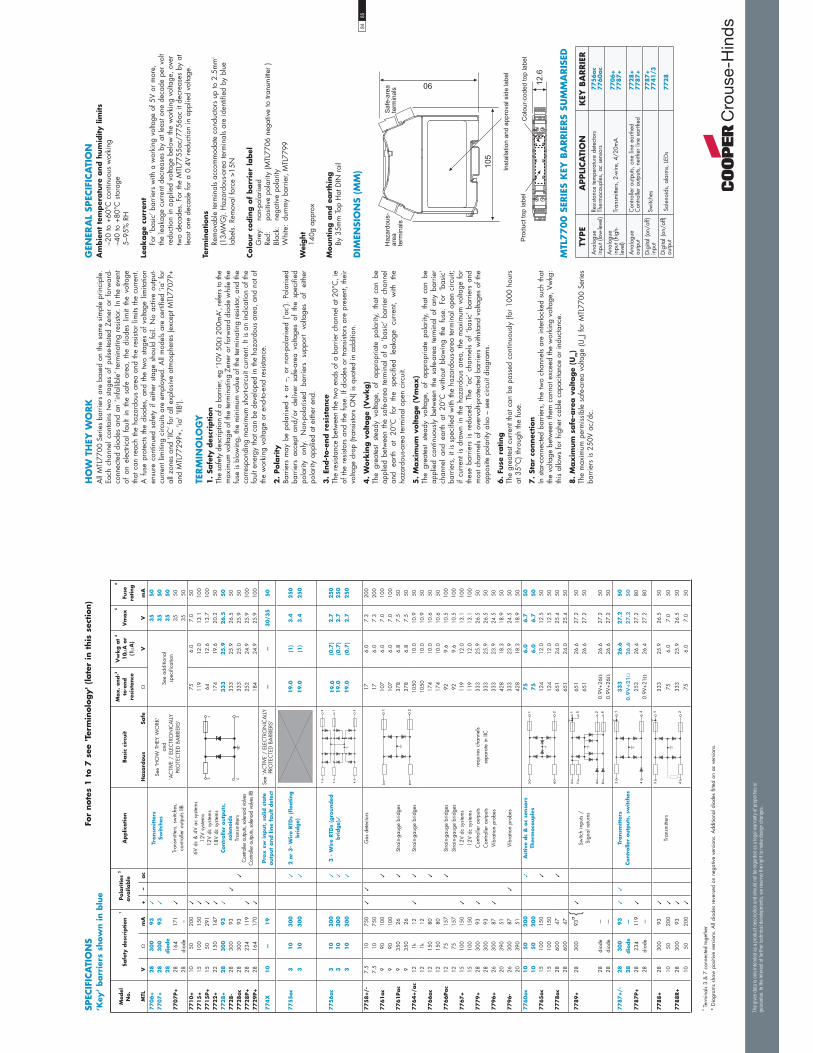
Model
N
o.
Safe
ty d
escr
iption
1Pola
rities
2
ava
ilable
Applic
ation
Basi
c ci
rcuit
Max
. en
d-3
to-e
nd
resi
stance
Vw
kg a
t 4
10
A o
r(1
A)
5
Vm
ax
6
Fuse
ra
ting
MTL
Vm
A+
–ac
Haza
rdous
Safe
VV
mA
77
06
+2
83
00
93
✓Tr
ansm
itte
rsSw
itch
es
Tran
smitt
ers,
sw
itche
s,
cont
rolle
r ou
tput
s IIB
See
'HO
W T
HEY
WO
RK'
and
'AC
TIVE
/ E
LEC
TRO
NIC
ALL
YPR
OTE
CTE
D B
ARR
IERS
'
See
addi
tiona
l sp
ecifi
catio
n
35
50
77
07
+2
83
00
93
✓3
55
02
8dio
de
35
50
77
07
P+
2816
417
1✓
3550
28di
ode
–35
507
71
0+
1050
200
✓6V
dc
& 4
V ac
sys
tem
s12
V sy
stem
s12
V dc
sys
tem
s18
V dc
sys
tem
sCo
ntro
ller
outp
uts,
so
leno
ids
Tran
smitt
ers
Con
trolle
r out
puts,
solen
oid
valve
sC
ontro
ller o
utpu
ts, so
lenoi
d va
lves I
IB
756.
07.
050
77
15
+15
100
150
✓11
912
.013
.110
07
71
5P+
1550
291
✓64
12.6
13.7
100
77
22
+22
150
147
✓17
419
.620
.250
77
28
+2
83
00
93
✓3
33
25
.92
6.5
50
77
28
-28
300
93✓
333
25.9
26
.550
77
28
ac
2830
093
✓33
325
.025
.950
77
28
P+
2823
411
9✓
252
24.9
25.9
100
77
29
P+
2816
417
0✓
184
24.9
25.9
100
77
4X
10
—1
9Pro
x s
w input,
solid
sta
te
outp
ut
and lin
e fa
ult d
etec
tSe
e 'A
CTI
VE /
ELE
CTR
ON
ICA
LLY
PRO
TEC
TED
BA
RRIE
RS'
——
30
/35
50
77
55
ac
31
03
00
✓2
or
3-
Wir
e RTD
s (f
loating
bri
dge)
19
.0(1
)3
.42
50
31
03
00
✓1
9.0
(1)
3.4
25
0
77
56
ac
31
03
00
✓3
- W
ire
RTD
s (g
rounded
bri
dge)
✓1
9.0
(0.7
)2
.72
50
31
03
00
✓1
9.0
(0.7
)2
.72
50
31
03
00
✓1
9.0
(0.7
)2
.72
50
77
58
+/-
7.5
1075
0✓
✓G
as d
etec
tors
176.
07.
320
07.
510
750
176.
07.
320
07
76
1ac
990
100
✓10
76.
07.
010
09
9010
010
76.
07.
010
07
76
1Pac
935
026
✓St
rain
-gau
ge b
ridge
s37
86.
87.
550
935
026
378
6.8
7.5
507
76
4+
/ac
121k
12✓
✓St
rain
-gau
ge b
ridge
s10
5010
.010
.9
5012
1k12
1050
10.0
10.9
50
77
66
ac
1215
080
✓17
410
.010
.650
1215
080
174
10.0
10.6
507
76
6Pac
1275
157
✓St
rain
-gau
ge b
ridge
s92
9.6
10.5
100
1275
157
Stra
in-g
auge
brid
ges
929.
610
.510
07
76
7+
1510
015
0✓
12V
dc s
yste
ms
119
12.0
13.1
100
1510
015
012
V dc
sys
tem
s11
912
.013
.110
07
77
9+
2830
093
✓C
ontro
ller
outp
uts
requ
ires
chan
nels
333
25.9
26.5
5028
300
93C
ontro
ller
outp
uts
sepa
rate
in II
C33
325
.926
.550
77
96
+26
300
87✓
Vibr
atio
n pr
obes
333
23.9
24.5
5020
390
5142
818
.318
.950
77
96
-26
300
87✓
Vibr
atio
n pr
obes
333
23.9
24.5
5020
390
5142
818
.318
.950
77
60
ac
10
50
20
0✓
Act
ive
dc
& a
c se
nso
rs
Ther
moco
uple
s7
56
.06
.75
01
05
02
00
75
6.0
6.7
50
77
65
ac
1510
015
0✓
124
12.0
12.5
5015
100
150
124
12.0
12.5
507
77
8ac
2860
047
✓65
124
.025
.450
2860
047
651
24.0
25.4
50
77
89
+28
300
93a
✓Sw
itch
inpu
ts /
Sign
al r
etur
ns
651
26.6
27.2
5065
126
.627
.250
28di
ode
—0.
9V+2
626
.627
.250
28di
ode
—0.
9V+2
626
.627
.250
77
87
+/-
28
30
09
3✓
✓Tr
ansm
itte
rs
Cont
rolle
r out
put
s, s
witc
hes
33
32
6.6
27
.25
02
8dio
de
—0
.9V
+2
12
6.6
27
.25
07
78
7P+
2823
411
9✓
253
26.4
27.2
8028
diod
e—
0.9V
+21
26.4
27.2
80
77
88
+28
300
93✓
Tr
ansm
itter
s33
325
.926
.550
1050
200
✓75
6.0
7.0
50
77
88
R+
2830
093
✓33
325
.926
.550
1050
200
✓75
6.0
7.0
50
��
��
��
��
��
��
��
��
���
��
� ��
��
��
��
� �
� �
SPEC
IFIC
ATI
ON
S‘K
ey’
barr
iers
show
n in b
lue
For
note
s 1
to 7
see
'Ter
min
olo
gy' (
late
r in
this
sec
tion)
a Ter
min
als
3 &
7 c
onne
cted
toge
ther
* D
iagr
ams
show
pos
itive
ver
sion
s. A
ll di
odes
rev
erse
d on
neg
ativ
e ve
rsio
ns. A
dditi
onal
dio
des
fitte
d on
ac
vers
ions
.
{
The
giv
en d
ata
is o
nly
inte
nded
as
a pro
duct
des
crip
tion
and
shou
ld n
ot b
e re
gar
ded
as
a le
gal
war
ranty
of pro
per
ties
or
guar
ante
e. In
the
inte
rest
of
furt
her
tec
hnic
al d
evel
opm
ents
, w
e re
serv
e th
e ri
ght
to m
ake
des
ign
chan
ges
.
GEN
ERA
L SP
ECIF
ICA
TIO
NA
mbie
nt
tem
per
atu
re a
nd h
um
idity lim
its
–20
to +
60°C
con
tinuo
us w
orki
ng–4
0 to
+80
°C s
tora
ge5–
95%
RH
Leak
age
curr
ent
For
‘bas
ic’ b
arrie
rs w
ith a
wor
king
vol
tage
of 5
V or
mor
e,
the
leak
age
curr
ent d
ecre
ases
by
at le
ast o
ne d
ecad
e pe
r vo
lt re
duct
ion
in a
pplie
d vo
ltage
bel
ow th
e w
orki
ng v
olta
ge, o
ver
two
deca
des.
For
the
MTL
7755
ac/7
756a
c it
decr
ease
s by
at
leas
t one
dec
ade
for
a 0.
4V r
educ
tion
in a
pplie
d vo
ltage
.
Term
inations
Rem
ovab
le te
rmin
als
acco
mm
odat
e co
nduc
tors
up
to 2
.5m
m2
(13A
WG
). H
azar
dous
-are
a te
rmin
als
are
iden
tifie
d by
blu
e la
bels.
Rem
oval
forc
e >1
5N
Colo
ur
codin
g o
f barr
ier
label
Gre
y:
non-
pola
rised
Red:
po
sitiv
e po
larit
y (M
TL77
06 n
egat
ive
to tr
ansm
itter
)Bl
ack:
ne
gativ
e po
larit
yW
hite
: du
mm
y ba
rrie
r, M
TL77
99
Wei
ght
140g
app
rox
Mounting a
nd e
art
hin
gBy
35m
m T
op H
at D
IN r
ail
DIM
ENSI
ON
S (M
M)
MTL
7700 S
ERIE
S K
EY B
ARRIE
RS
SUM
MA
RIS
ED
HO
W T
HEY
WO
RK
All
MTL
7700
Ser
ies
barr
iers
are
bas
ed o
n th
e sa
me
sim
ple
prin
cipl
e.
Each
cha
nnel
con
tain
s tw
o sta
ges
of p
ulse
-teste
d Ze
ner
or f
orw
ard-
conn
ecte
d di
odes
and
an
‘infa
llibl
e’ te
rmin
atin
g re
sisto
r. In
the
even
t of
an
elec
trica
l fa
ult
in t
he s
afe
area
, th
e di
odes
lim
it th
e vo
ltage
th
at c
an r
each
the
haza
rdou
s ar
ea a
nd th
e re
sisto
r lim
its th
e cu
rren
t. A
fus
e pr
otec
ts th
e di
odes
, an
d th
e tw
o sta
ges
of v
olta
ge l
imita
tion
ensu
re c
ontin
ued
safe
ty i
f ei
ther
sta
ge s
houl
d fa
il. N
o ac
tive
outp
ut-
curr
ent l
imiti
ng c
ircui
ts ar
e em
ploy
ed. A
ll m
odel
s ar
e ce
rtifie
d ‘ia
’ for
al
l zon
es a
nd ‘I
IC’ f
or a
ll ex
plos
ive
atm
osph
eres
(exc
ept M
TL77
07P+
an
d M
TL77
29P+
, 'ia
' 'IIB
').
TER
MIN
OLO
GY
1.
Safe
ty d
escr
iption
The
safe
ty d
escr
iptio
n of
a b
arrie
r, eg
‘10V
50
200
mA’
, ref
ers
to th
e m
axim
um v
olta
ge o
f the
term
inat
ing
Zene
r or f
orw
ard
diod
e w
hile
the
fuse
is b
low
ing,
the
min
imum
val
ue o
f the
term
inat
ing
resi
stor,
and
the
corr
espo
ndin
g m
axim
um s
hort-
circ
uit c
urre
nt. I
t is
an in
dica
tion
of th
e fa
ult e
nerg
y th
at c
an b
e de
velo
ped
in th
e ha
zard
ous
area
, and
not
of
the
wor
king
vol
tage
or
end-
to-e
nd r
esis
tanc
e.
2.
Pola
rity
Barr
iers
may
be
pola
rised
+ o
r –,
or
non-
pola
rised
(‘a
c’).
Pola
rised
ba
rrie
rs a
ccep
t an
d/or
del
iver
saf
e-ar
ea v
olta
ges
of t
he s
peci
fied
pola
rity
only.
N
on-p
olar
ised
ba
rrie
rs
supp
ort
volta
ges
of
eith
er
pola
rity
appl
ied
at e
ither
end
.
3.
End-t
o-e
nd r
esis
tance
The
resi
stanc
e be
twee
n th
e tw
o en
ds o
f a b
arrie
r ch
anne
l at 2
0°C
, ie
of th
e re
sisto
rs a
nd th
e fu
se.
If di
odes
or
trans
isto
rs a
re p
rese
nt,
thei
r vo
ltage
dro
p (tr
ansi
stors
ON
) is
quot
ed in
add
ition
.
4.
Work
ing v
oltage
(Vw
kg)
The
grea
test
stead
y vo
ltage
, of
app
ropr
iate
pol
arity
, th
at c
an b
e ap
plie
d be
twee
n th
e sa
fe-a
rea
term
inal
of
a ‘b
asic
’ ba
rrie
r ch
anne
l an
d ea
rth
at
20°C
fo
r th
e sp
ecifi
ed
leak
age
curr
ent,
with
th
e ha
zard
ous-a
rea
term
inal
ope
n ci
rcui
t.
5.
Max
imum
voltage
(Vm
ax
)Th
e gr
eate
st ste
ady
volta
ge,
of a
ppro
pria
te p
olar
ity,
that
can
be
appl
ied
cont
inuo
usly
bet
wee
n th
e sa
fe-a
rea
term
inal
of
any
barr
ier
chan
nel
and
earth
at
20°C
with
out
blow
ing
the
fuse
. Fo
r ‘b
asic
’ ba
rrie
rs, i
t is
spec
ified
with
the
haza
rdou
s-are
a te
rmin
al o
pen
circ
uit;
if cu
rren
t is
draw
n in
the
haza
rdou
s ar
ea,
the
max
imum
vol
tage
for
th
ese
barr
iers
is
redu
ced.
The
‘ac
’ ch
anne
ls of
‘ba
sic’
bar
riers
and
m
ost c
hann
els
of o
verv
olt-p
rote
cted
bar
riers
with
stand
vol
tage
s of
the
oppo
site
pol
arity
also
– s
ee c
ircui
t dia
gram
s.
6.
Fuse
rating
The
grea
test
curr
ent t
hat c
an b
e pa
ssed
con
tinuo
usly
(for
100
0 ho
urs
at 3
5°C
) thr
ough
the
fuse
.
7.
Star
connec
tion
In s
tar-c
onne
cted
bar
riers
, th
e tw
o ch
anne
ls ar
e in
terlo
cked
suc
h th
at
the
volta
ge b
etw
een
them
can
not e
xcee
d th
e w
orki
ng v
olta
ge, V
wkg
: th
is a
llow
s fo
r hi
gher
cab
le c
apac
itanc
e or
indu
ctan
ce.
8.
Max
imum
safe
-are
a v
oltage
(Um)
The
max
imum
per
mis
sibl
e sa
fe-a
rea
volta
ge (U
m) f
or M
TL77
00 S
erie
s ba
rrie
rs is
250
V ac
/dc.
��
$�;�6�
�4,
���
���
5���4
"�<�,���
���
5���4
���
���
��4������5�����
6���
������456����=�
�
+�6�
����
����=�
�-����
,�6�
6�������=�
�
TYPE
APPLI
CA
TIO
NK
EY B
ARRIE
RA
nalo
gue
inpu
t (lo
w-le
vel)
Resi
stanc
e te
mpe
ratu
re d
etec
tors
Ther
moc
oupl
es, a
c se
nsor
s7
75
6ac
77
60
ac
Ana
logu
ein
put (
high
-le
vel)
Tran
smitt
ers,
2-w
ire, 4
/20m
A7
70
6+
77
87
+
Ana
logu
eou
tput
Con
trolle
r ou
tput
s, o
ne li
ne e
arth
edC
ontro
ller
outp
uts,
nei
ther
line
ear
thed
77
28
+7
78
7+
Dig
ital (
on/o
ff)in
put
Switc
hes
77
87
+7
74
1/3
Dig
ital (
on/o
ff)ou
tput
Sole
noid
s, a
larm
s, L
EDs
77
28
8485

AC
TIV
E /
EL
EC
TR
ON
ICA
LLY
PR
OT
EC
TE
D B
AR
RIE
RS
ACT
IVE
/ EL
ECTR
ON
ICA
LLY P
ROTE
CTED
BA
RRIE
RS
The
follo
win
g ba
rrie
rs h
ave
built
-in o
verv
olt p
rote
ctio
n, a
llow
ing
thei
r us
e w
ith u
nreg
ulat
ed p
ower
sup
plie
s. In
man
y ap
plic
atio
ns, e
g, s
enso
r in
puts
or c
ontro
ller
outp
uts,
the
re i
s in
suffi
cien
t po
wer
ava
ilabl
e to
bl
ow th
e ba
rrie
r fu
se a
nd th
is a
dditi
onal
pro
tect
ion
is n
ot n
eces
sary
. H
owev
er,
whe
re th
e ba
rrie
r is
con
nect
ed to
a p
ower
sup
ply,
eg,
for
en
ergi
sing
tra
nsm
itter
s, s
witc
hes,
sol
enoi
ds o
r lo
cal a
larm
s, o
verv
olt
prot
ectio
n al
low
s th
e ba
rrie
rs t
o be
use
d w
ith u
nreg
ulat
ed s
uppl
ies
and
also
giv
es p
rote
ctio
n ag
ains
t fau
lty w
iring
dur
ing
com
mis
sion
ing.
MTL
7706
+ fo
r 'sm
art'
2-w
ire
4/20
mA
tran
smitt
ers
The
MTL
7706
+ is
a 1
-cha
nnel
shu
nt-d
iode
saf
ety
barr
ier,
with
bui
lt-in
ele
ctro
nic
over
volt
prot
ectio
n, f
or e
nerg
isin
g a
2-w
ire,
4/20
mA
tra
nsm
itter
in a
haz
ardo
us a
rea.
It is
pow
ered
from
a p
ositi
ve s
uppl
y of
20–
35V
dc a
nd d
eliv
ers
a 4/
20m
A s
igna
l in
to a
n ea
rthed
loa
d in
the
saf
e ar
ea.
It is
pro
of a
gain
st sh
ort
circ
uits
in t
he f
ield
and
in
the
saf
e ar
ea a
nd i
s ex
trem
ely
accu
rate
. Th
e M
TL77
06+
will
pa
ss i
ncom
ing
com
mun
icat
ion
sign
als
up t
o 10
kHz
from
a ‘
smar
t’ tra
nsm
itter
, w
hile
in th
e ou
tgoi
ng d
irect
ion
it w
ill p
ass
sign
als
of a
ny
frequ
ency
like
ly to
be
enco
unte
red.
Sinc
e th
e M
TL77
06+
has
no r
etur
n ch
anne
l for
ene
rgis
ing
the
load
, th
e en
tire
outp
ut o
f the
sin
gle
‘28V
’ cha
nnel
is a
vaila
ble
to p
ower
the
trans
mitt
er, p
rovi
ding
hig
h ou
tput
cap
abili
ty. T
his
chan
nel i
s ne
gativ
ely
pola
rised
, an
d th
e sa
fe-a
rea
sign
al i
s in
fac
t th
e ve
ry c
urre
nt t
hat
retu
rns
thro
ugh
it fro
m t
he h
azar
dous
are
a, t
he n
ovel
circ
uit
bein
g en
ergi
sed
by a
bui
lt-in
flo
atin
g dc
sup
ply
deriv
ed f
rom
the
ext
erna
l dc
sou
rce
of p
ower
.
To p
reve
nt a
ny le
akag
e th
roug
h th
e ze
ner
diod
es a
nd m
axim
ise
the
outp
ut v
olta
ge a
vaila
ble
at 2
0mA
, the
floa
ting
supp
ly is
giv
en a
risi
ng
volta
ge/c
urre
nt c
hara
cter
istic
. A
sep
arat
e ci
rcui
t lim
its th
e cu
rren
t to
prot
ect t
he fu
se in
the
even
t of a
sho
rt ci
rcui
t in
the
haza
rdou
s ar
ea.
With
a 2
0V s
uppl
y, th
e ba
rrie
r w
ill d
eliv
er 1
6.2V
min
imum
at 2
0mA
fo
r th
e tra
nsm
itter
and
lin
es a
nd c
onsu
mes
typ
ical
ly 4
5mA
at
24V
oper
atio
n.
BA
SIC C
IRCU
IT
AD
DIT
ION
AL
SPEC
IFIC
ATI
ON
Safe
ty d
escr
iption
28V
300
93m
ASu
pply
voltage
20 to
35V
dc
w.r.
t ear
thO
utp
ut
curr
ent
4 to
20
mA
Voltage
ava
ilable
to t
ransm
itte
r and lin
es16
.2V
@ 2
0mA
with
250
load
(neg
ativ
e w
.r.t.
earth
)11
.0V
@ 2
0mA
with
500
load
(neg
ativ
e w
.r.t.
earth
)
Acc
ura
cy±2
μA u
nder
all
cond
ition
sSa
fe-a
rea load r
esis
tance
0 to
500
Supply
curr
ent
45m
A ty
pica
l at 2
0mA
and
24V
sup
ply
60m
A m
axim
um a
t 20m
A a
nd 2
0V s
uppl
y
MTL
7707
+ FO
R SW
ITCH
INPU
TS A
ND
SW
ITCH
ED O
UTP
UTS
The
MTL
7707
+ is
a 2
-cha
nnel
shu
nt-d
iode
saf
ety
barr
ier
sim
ilar
to t
he M
TL77
87+
but
with
bui
lt-in
ele
ctro
nic
over
volt
prot
ectio
n.
It is
int
ende
d pr
imar
ily f
or s
afeg
uard
ing
a ha
zard
ous-a
rea
switc
h co
ntro
lling
a r
elay
, op
to-c
oupl
er o
r ot
her
safe
-are
a lo
ad f
rom
an
unre
gula
ted
dc s
uppl
y in
the
safe
are
a.
The
outg
oing
cha
nnel
acc
epts
supp
ly v
olta
ges
up t
o +3
5V a
nd i
s pr
otec
ted
agai
nst
reve
rse
volta
ges:
the
ret
urn
chan
nel
is u
naffe
cted
by
vol
tage
s up
to +
250V
.
In n
orm
al o
pera
tion
the
prot
ectio
n ci
rcui
t in
trodu
ces
only
a s
mal
l vo
ltage
dro
p an
d sh
unts
less
than
1m
A to
ear
th,
so i
ts ov
eral
l effe
ct
is
min
imal
. If
the
supp
ly
volta
ge
exce
eds
abou
t 27
V,
how
ever
, ca
usin
g th
e Ze
ner
diod
es t
o co
nduc
t –
or i
f th
e sa
fe-a
rea
load
has
a
very
low
res
ista
nce
– th
e su
pply
cur
rent
is li
mite
d au
tom
atic
ally
to
50m
A,
prot
ectin
g th
e fu
se a
nd p
ower
sup
ply
and
enab
ling
the
loop
to
con
tinue
wor
king
.
BA
SIC C
IRCU
IT
AD
DIT
ION
AL
SPEC
IFIC
ATI
ON
Safe
ty d
escr
iption
28V
300
93m
A, t
erm
inal
s 1
to 3
28V
Dio
de, t
erm
inal
s 2
-4Su
pply
voltage
10 to
35V
dc
with
res
pect
to e
arth
Outp
ut
curr
ent
Up
to 3
5mA
ava
ilabl
eM
ax
imum
voltage
dro
p
(at
20ºC
, cu
rren
t not
limited
)Io
ut x
345
+ 0.
3V, t
erm
inal
s 1
to 3
Iout
x 2
5+
0.9V
, ter
min
als
4 to
2Su
pply
curr
ent
Iout
+ 1
.6m
A, s
uppl
y <2
6VLim
ited
to 5
0mA
, sup
ply
>28V
or
low
load
res
ista
nce
MTL
7707P+ F
OR S
WIT
CH
IN
PU
TS A
ND
SWIT
CH
ED O
UTP
UTS
, 2W
TRA
NSM
ITTE
RS
(IIB
GA
SES)
The
MTL
7707
P+ i
s a
two-
chan
nel
shun
t-dio
de s
afet
y ba
rrie
r si
mila
r to
the
MTL
7787
P+,
but
is d
esig
ned
for
use
with
gro
up I
IB g
ases
an
d fe
atur
es b
uilt-
in e
lect
roni
c ov
ervo
lt pr
otec
tion
allo
win
g us
e w
ith
unre
gula
ted
pow
er s
uppl
ies
up to
35V
dc.
It is
inte
nded
prim
arily
as
a lo
w c
ost s
olut
ion
for
driv
ing
IIB c
ertif
ied
2-w
ire 4
/20m
A tr
ansm
itter
s,
but c
an a
lso b
e us
ed w
ith c
ontro
ller
outp
uts
with
cur
rent
mon
itorin
g,
sole
noid
val
ves
and
switc
hes.
To
prot
ect t
he fu
se a
nd e
nabl
e th
e lo
op
to c
ontin
ue w
orki
ng,
the
supp
ly c
urre
nt i
s lim
ited
auto
mat
ical
ly a
t 50
mA
sho
uld
the
outp
ut b
e sh
ort-c
ircui
ted
or e
xces
s vo
ltage
app
lied.
Haza
rdous
Are
aSa
feA
rea
�� �
�
0'!:
����
4�����56
���
-����
�5�5�
��
����
�
1�44�6���A�
����
�8 B
8�
B�
�C����
1�44�6���A�
����
�C��
��
-����
�5�5�
%�������
����
��0��6��
&7
Haza
rdous
Are
aSa
feA
rea
The
giv
en d
ata
is o
nly
inte
nded
as
a pro
duct
des
crip
tion
and
shou
ld n
ot b
e re
gar
ded
as
a le
gal
war
ranty
of pro
per
ties
or
guar
ante
e. In
the
inte
rest
of
furt
her
tec
hnic
al d
evel
opm
ents
, w
e re
serv
e th
e ri
ght
to m
ake
des
ign
chan
ges
.
MTL
7742 P
RO
XIM
ITY
SEN
SOR O
R S
WIT
CH
INPU
T W
ITH
SO
LID
STA
TE O
UTP
UT
The
MTL
7742
is a
sin
gle
chan
nel s
witc
h/pr
ox in
put b
arrie
r w
ith a
n op
en c
olle
ctor
sol
id s
tate
int
erfa
ce t
o th
e sa
fe a
rea
equi
pmen
t. Th
e so
lid s
tate
sw
itch
is e
spec
ially
use
ful
for
high
fre
quen
cy s
witc
hing
ap
para
tus
incl
udin
g pu
lse a
nd r
otat
iona
l se
nsor
s. T
he p
ower
bus
te
rmin
al c
an b
e us
ed t
o co
nnec
t po
wer
to
the
mod
ule
and
the
inpu
t po
wer
sup
ply
rang
e m
akes
the
mod
ule
suita
ble
for
use
with
un
regu
late
d su
pplie
s.
BA
SIC C
IRCU
IT
AD
DIT
ION
AL
SPEC
IFIC
ATI
ON
Safe
ty d
escr
iption
10V
19m
ASu
pply
voltage
20 to
35V
dc
with
res
pect
to e
arth
Input
chara
cter
istics
Out
put e
nerg
ised
if in
put >
2.1m
A(<
2k)
Out
put d
e-en
ergi
sed
if in
put <
1.2m
A(>
10k
)O
utp
ut
chara
cter
istics
Ope
ratin
g fre
quen
cy
dc to
2.5
kHz
Max
off-
state
vol
tage
35
VM
ax o
ff-sta
te le
akag
e 10
μAM
ax o
n-sta
te v
olta
ge d
rop
<1.4
1V @
50m
A
<1.2
2V @
2m
A
typi
cally
<1V
M
ax o
n-sta
te c
urre
nt
50m
ASu
pply
curr
ent
20m
A m
axim
um @
24V
MTL
7743 2
CH
AN
NEL
PRO
XIM
ITY
SEN
SOR
OR S
WIT
CH
IN
PU
T A
ND
REL
AY
OU
TPU
TSTh
e M
TL77
43 is
a d
ual c
hann
el s
witc
h/pr
ox s
enso
r inp
ut b
arrie
r with
a
rela
y in
terfa
ce.
This
mod
ule
is i
deal
for
app
licat
ions
whe
re h
igh
chan
nel
pack
ing
dens
ities
are
req
uire
d fo
r di
gita
l in
puts.
Pow
er i
s co
nnec
ted
usin
g th
e po
wer
bus
term
inal
.
BA
SIC C
IRCU
IT
AD
DIT
ION
AL
SPEC
IFIC
ATI
ON
Safe
ty d
escr
iption
10V
19m
ASu
pply
voltage
22.9
to 3
0V d
c w
ith r
espe
ct to
ear
thIn
put
chara
cter
istics
Rela
y en
ergi
sed
if in
put >
2.1m
A(<
2k)
Rela
y de
-ene
rgis
ed if
inpu
t <1.
2mA
(>10
k)
Rel
ay C
onta
cts
50V
ac 0
.5A
. Re
sisti
ve30
V dc
, 1A
. Re
sisti
veSu
pply
curr
ent
45m
A m
axim
um @
24V
Res
ponse
tim
e <1
0ms
BA
SIC C
IRCU
IT
AD
DIT
ION
AL
SPEC
IFIC
ATI
ON
Safe
ty d
escr
iption
28V
164
171
mA
, ter
min
als
1 to
328
V D
iode
, ter
min
als
4 to
2Su
pply
voltage
10 to
35V
dc
with
res
pect
to e
arth
Outp
ut
curr
ent
Up
to 3
5mA
ava
ilabl
eM
ax
imum
voltage
dro
p(a
t 20ºC
, cu
rren
t not
limited
)Io
ut x
218
+ 0.
3V, t
erm
inal
s 1
to 3
Iout
x 2
0.1
+ 0.
9V, t
erm
inal
s 4
to 2
Supply
curr
ent
Iout
+ 1
.6m
A, s
uppl
y <2
6VLim
ited
to 5
0mA
, sup
ply
>28V
or
low
load
res
ista
nce
MTL
7741 P
RO
XIM
ITY
SEN
SOR O
R S
WIT
CH
INPU
T A
ND
REL
AY
OU
TPU
TTh
e M
TL77
41 i
s a
sing
le c
hann
el s
witc
h/pr
ox i
nput
bar
rier
with
ch
ange
over
rel
ay c
onta
cts
actin
g as
the
saf
e ar
ea i
nter
face
. Re
lay
cont
acts
prov
ide
a un
iver
sal
inte
rface
cap
able
of
switc
hing
a w
ide
rang
e of
sig
nals
incl
udin
g ac
, lo
w l
evel
and
hig
h le
vel
volta
ges.
Ph
ase
reve
rsal
is
achi
eved
by
conn
ectin
g th
e no
rmal
ly o
pen
or
norm
ally
clo
sed
cont
acts
as r
equi
red.
The
pow
er b
us t
erm
inal
may
be
use
d to
con
nect
the
mod
ule
to a
pow
er s
ourc
e.
BA
SIC C
IRCU
IT
AD
DIT
ION
AL
SPEC
IFIC
ATI
ON
Safe
ty d
escr
iption
10V
19m
ASu
pply
voltage
22.9
to 3
0V d
c w
ith r
espe
ct to
ear
thIn
put
chara
cter
istics
Rela
y en
ergi
sed
if in
put >
2.1m
A(<
2k)
Rela
y de
-ene
rgis
ed if
inpu
t <1.
2mA
(>10
k)
Rel
ay C
onta
cts
50V
ac 0
.5A
. Re
sisti
ve30
V dc
, 1A
. Re
sisti
ve
Supply
curr
ent
26m
A m
axim
um @
24V
Res
ponse
tim
e <1
0ms
�� �
�
0'!:
����
4�����56
���
-����
�5�5�
��
����
�
1�44�6���A�
����
�8 B
Haza
rdous
Are
aSa
feA
rea
� �
1�44�6���A�
-�2
/�
/-
� ��
Haza
rdous
Are
aSa
feA
rea
� ���
1�44�6���
A� -$�
-$�
���
8 8B B
Haza
rdous
Are
aSa
feA
rea
� �
-$�
1�44�6���A�
���
8 B
Haza
rdous
Are
aSa
feA
rea
8687
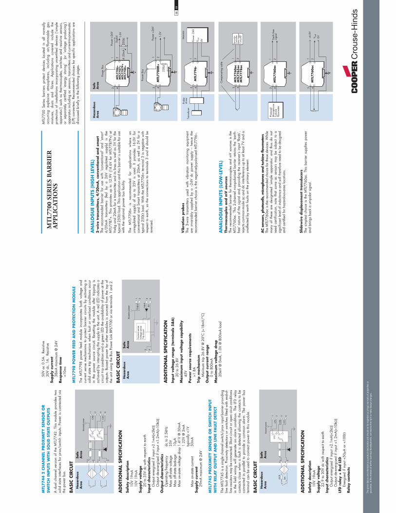
MTL
7744 2
CH
AN
NEL
PRO
XIM
ITY
SEN
SOR O
R
SWIT
CH
IN
PU
TS W
ITH
SO
LID
STA
TE O
UTP
UTS
A d
ual c
hann
el v
ersi
on o
f th
e M
TL77
42.
This
mod
ule
prov
ides
tw
o so
lid s
tate
inte
rface
s fo
r pr
ox/s
witc
h in
puts.
Pow
er is
con
nect
ed v
ia
the
pow
er b
us.
BA
SIC C
IRCU
IT
AD
DIT
ION
AL
SPEC
IFIC
ATI
ON
Safe
ty d
escr
iption
10V
19m
A10
V 19
mA
Supply
voltage
20 to
35V
dc
with
res
pect
to e
arth
Input
chara
cter
istics
Out
put e
nerg
ised
if in
put >
2.1m
A(<
2k)
Out
put d
e-en
ergi
sed
if in
put <
1.2m
A(>
10k
)O
utp
ut
chara
cter
istics
Ope
ratin
g fre
quen
cy
dc to
2.5
kHz
Max
off-
state
vol
tage
35
VM
ax o
ff-sta
te le
akag
e 10
μAM
ax o
n-sta
te v
olta
ge d
rop
1.41
V @
50m
A
1.22
V @
2m
A
typi
cally
<1V
Max
on-
state
cur
rent
50
mA
Supply
curr
ent
29m
A m
axim
um @
24V
MTL
7745
PRO
XIM
ITY
SEN
SOR O
R S
WIT
CH
IN
PU
T W
ITH
REL
AY
OU
TPU
T A
ND
LIN
E FA
ULT
DET
ECT
The
MTL
7745
is a
sin
gle
chan
nel s
witc
h/pr
ox in
put b
arrie
r pro
vidi
ng
line
faul
t det
ectio
n. P
roxi
mity
det
ecto
rs o
r sw
itche
s fit
ted
with
end
-of-
line
resi
stors
may
be
conn
ecte
d. S
hort
circ
uit o
r ope
n ci
ruit
cond
ition
s in
the
fie
ld w
iring
will
gen
erat
e an
ala
rm c
ondi
tion.
The
LFD
rel
ay
cont
acts
clos
e w
hen
a fa
ult
is d
etec
ted
allo
win
g th
e co
ntac
ts to
be
conn
ecte
d in
par
alle
l to
pro
vide
a c
omm
on a
larm
. Th
e po
wer
bus
te
rmin
al c
an b
e us
ed to
con
nect
pow
er to
this
mod
ule.
BA
SIC C
IRCU
IT
AD
DIT
ION
AL
SPEC
IFIC
ATI
ON
Safe
ty d
escr
iption
10V
19m
ASu
pply
voltage
22.9
to 3
0V d
c w
ith r
espe
ct to
ear
thIn
put
chara
cter
istics
Out
put e
nerg
ised
if in
put >
2.1m
A(<
2k)
Out
put d
e-en
ergi
sed
if in
put <
1.2m
A(>
10k
)LF
D r
elay +
Red
LED
Ener
gise
d if
inpu
t <50
A o
r <1
00Rel
ay c
onta
cts
50V
ac 0
.5A
. Re
sisti
ve30
V dc
, 1A
. Re
sisti
veSu
pply
curr
ent
38m
A m
axim
um @
24V
Res
ponse
tim
e <1
0ms
MTL
7798 P
OW
ER F
EED
AN
D P
RO
TECTI
ON
MO
DU
LE
The
MTL
7798
pow
er f
eed
mod
ule
inco
rpor
ates
bot
h vo
ltage
and
cu
rren
t se
nse
mec
hani
sms
to p
rote
ct b
arrie
r ci
rcui
ts by
act
ivat
ing
a so
lid s
tate
trip
mec
hani
sm w
hen
faul
t or
ove
rload
con
ditio
ns o
ccur
in
the
pow
er s
ourc
e ci
rcui
t. Re
setti
ng t
he m
odul
e af
ter
tripp
ing
is
achi
eved
by
inte
rupt
ing
the
supp
ly to
the
unit.
A r
ed L
ED in
dica
tes
a ci
rcui
t trip
con
ditio
n an
d a
gree
n LE
D th
e av
aila
bilit
y of
pow
er a
t the
ou
tput
s. B
usse
d po
wer
for
oth
er m
odul
es i
s so
urce
d fro
m th
e to
p of
th
e un
it us
ing
the
Bus
Pow
er L
ink
BPL7
700
or v
ia te
rmin
als
1 an
d 2.
BA
SIC C
IRCU
IT
AD
DIT
ION
AL
SPEC
IFIC
ATI
ON
Input
voltage
range
(ter
min
als
5&
6)
20 to
26.
8VM
ax
imum
input
voltage
capabili
ty45
VPow
er s
ourc
e re
quir
emen
ts>1
.8A
Trip
mec
hanis
mM
inim
um tr
ip 2
6.8V
@ 2
0°C
(+18
mV/
°C)
Outp
ut
curr
ent
range
0 to
800
mA
Max
imum
voltage
dro
p20
mV
@ 0
mA
, 1.0
V @
800
mA
load
��%
��(
� �
-�2
-$�
1�44�6���A�
0)!
0)!
� ��
8 B
Haza
rdous
Are
aSa
feA
rea
� �
1�44�6���A�
������
�����
���� �
-�����4��4�
��������4��4�
&5��5�5�
Haza
rdous
Are
aSa
feA
rea
��� �
1�44�6���A� -$�
-$�
�� �
8 B 8 B
Haza
rdous
Are
aSa
feA
rea
The
giv
en d
ata
is o
nly
inte
nded
as
a pro
duct
des
crip
tion
and
shou
ld n
ot b
e re
gar
ded
as
a le
gal
war
ranty
of pro
per
ties
or
guar
ante
e. In
the
inte
rest
of
furt
her
tec
hnic
al d
evel
opm
ents
, w
e re
serv
e th
e ri
ght
to m
ake
des
ign
chan
ges
.
MTL
7700
Ser
ies
barr
iers
pro
tect
dev
ices
loc
ated
in
all
norm
ally
oc
curr
ing
expl
osiv
e at
mos
pher
es,
incl
udin
g ai
r/fla
mm
able
ga
s m
ixtu
res,
du
sts
and
fibre
s.
App
licat
ions
co
vere
d in
clud
e th
e pr
otec
tion
of i
nsta
llatio
ns i
ncor
pora
ting
unce
rtifie
d de
vice
s (‘s
impl
e ap
para
tus’
) su
ch a
s th
erm
ocou
ples
, sw
itche
s an
d re
sisti
ve s
enso
rs,
or s
epar
atel
y ce
rtifie
d ‘e
nerg
y sto
ring’
(o
r ‘v
olta
ge p
rodu
cing
’) ap
para
tus
incl
udin
g ac
sen
sors
, tra
nsm
itter
s an
d cu
rren
t-to-
pneu
mat
ic
(I/P)
con
verte
rs.
Reco
mm
ende
d ch
oice
s fo
r sp
ecifi
c ap
plic
atio
ns a
re
disc
usse
d br
iefly
in th
e fo
llow
ing
page
s.
MT
L77
00 S
ER
IES
BA
RR
IER
A
PP
LIC
ATIO
NS
AN
ALO
GU
E IN
PU
TS (
HIG
H L
EVEL
)2
-wir
e tr
ansm
itte
rs,
4/2
0m
A,
conve
ntional and s
mart
The
reco
mm
ende
d ba
rrie
r fo
r us
e w
ith '
conv
entio
nal'
and
'sm
art'
4/20
mA
tra
nsm
itter
s (fe
d by
a
26V
regu
late
d su
pply
) is
th
e M
TL77
87+.
Thi
s pr
ovid
es u
p to
12.
9V (
14.6
V fo
r M
TL77
87P+
) at
Vw
kg a
nd 2
0mA
for
a tra
nsm
itter
and
its
lines
as
wel
l as
5V fo
r th
e ty
pica
l 250
load
. Thi
s ap
plic
atio
n an
d th
is b
arrie
r is
suita
ble
for u
se
with
the
optio
nal p
ower
bus
faci
lity.
The
MTL
7706
+ is
re
com
men
ded
for
appl
icat
ions
w
here
an
un
regu
late
d su
pply
of
up t
o 35
V is
use
d. I
t pr
ovid
es 1
6.0V
for
co
nven
tiona
l an
d Sm
art
trans
mitt
ers
at 2
0mA
, as
wel
l as
5V
for
a ty
pica
l 250
load
. W
ith th
e M
TL77
06+
term
inal
3 is
neg
ativ
e w
ith
resp
ect t
o ea
rth,
so th
e co
nnec
tions
to te
rmin
als
3 an
d 4
shou
ld b
e re
vers
ed.
AN
ALO
GU
E IN
PU
TS (
LOW
-LEV
EL)
Ther
moco
uple
s and m
V s
ourc
esTh
e re
com
men
ded
barr
ier
for
ther
moc
oupl
es a
nd m
V so
urce
s is
the
MTL
7760
ac.
This
2-c
hann
el n
on-p
olar
ised
bar
rier
reta
ins
the
‘ear
th-
free’
nat
ure
of th
e si
gnal
and
, pr
ovid
ing
the
rece
iver
’s in
put ‘
float
s’,
reje
cts
com
mon
-mod
e ac
and
dc
inte
rfere
nce
up to
at l
east
7V a
nd is
un
affe
cted
by
earth
faul
ts on
the
prim
ary
elem
ent.
�
� ����::�� /
���::�� /
���:::; /
��������
1�%�������
������//��
1� �����
1� ��%����%/��#��
3 4
1 2M
TL7760ac
Earth
free
sign
al
Phot
ocel
lM
icro
phon
eTu
rbin
eFl
owm
eter
+6.0
V3 4
1 2M
TL7760ac
V out
0V
3 4
1 2M
TL7796-
Pow
er -2
4V
V out
0V
Prob
edr
iver
Tran
sduc
er
Mon
itor
3 4
1 2M
TL7788R+
250Ω
1-5V
Pow
er +
26V
Pow
er B
us
�
� �
���
�,� 3
��!����&�
+�/%��
��!��2��
�,��
���::��<
���::;:<
���::;:�<
���::;;<
Haza
rdous
Are
aSa
feA
rea
Vib
ration p
robes
The
3-w
ire t
rans
mitt
ers
used
with
vib
ratio
n m
onito
ring
equi
pmen
t ar
e in
varia
bly
supp
lied
by a
–24
V dc
pow
er s
uppl
y –
henc
e th
e re
com
men
ded
barr
ier
choi
ce is
the
nega
tivel
y-po
laris
ed M
TL77
96–.
Slid
ewir
e dis
pla
cem
ent
transd
uce
rsTh
e si
mpl
est
choi
ce i
s th
e M
TL77
60ac
. Th
is b
arrie
r su
pplie
s po
wer
an
d br
ings
bac
k a
unip
olar
sig
nal.
AC
sens
ors,
pho
toce
lls, m
icro
phon
es a
nd tu
rbin
e flo
wm
eter
sTh
e M
TL77
60ac
is th
e re
com
men
ded
choi
ce fo
r the
se d
evic
es. W
hile
m
any
of t
hese
are
des
igna
ted
‘sim
ple
appa
ratu
s’ a
nd t
hus
do n
ot
need
cer
tific
atio
n, n
ote
that
som
e ac
sen
sors
may
be
subj
ect
to a
si
gnifi
cant
leve
l of i
nduc
tanc
e an
d w
ill th
eref
ore
need
to b
e de
sign
ed
and
certi
fied
for
haza
rdou
s-are
a lo
catio
ns.
8889

RTD
sFo
r 3-
wire
RTD
s, a
sin
gle
MTL
7755
ac b
arrie
r is
the
mos
t eco
nom
ical
ch
oice
. Thi
s is
sui
tabl
e fo
r us
e w
ith a
floa
ting
brid
ge –
the
two
lead
s fro
m t
he b
ridge
arm
s ar
e pr
otec
ted
by t
he b
arrie
r w
ith t
he t
hird
(s
uppl
y) le
ad b
eing
ear
thed
thro
ugh
the
barr
ier.
The
barr
ier h
as a
low
en
d-to
-end
resi
stanc
e of
onl
y 19
/cha
nnel
to m
inim
ise
span
cha
nges
an
d its
cha
nnel
s tra
ck w
ithin
0.1
5 (b
etw
een
–20°
C a
nd +
60°C
) to
min
imis
e ze
ro s
hift
with
tem
pera
ture
.
STRA
IN-G
AU
GE
BRID
GES
Single
str
ain
-gauge
bri
dges
This
sho
ws
an a
rran
gem
ent u
sing
two
or th
ree
barr
iers
, whi
ch is
saf
e in
IIC
gas
es.
With
the
MTL
7761
ac,
the
circ
uit
is p
ower
ed f
rom
a
14V,
230
sou
rce;
if th
e br
idge
res
ista
nce
is 2
30, t
hen
the
brid
ge
volta
ge i
s 7V
. If
the
brid
ge r
esis
tanc
e is
350
, th
en t
he b
ridge
vo
ltage
is 8
.4V.
An
MTL
7764
ac c
an b
e us
ed to
sen
se th
e br
idge
sup
ply
volta
ge.
An
MTL
7761
ac is
use
d he
re fo
r th
e m
V ou
tput
.
An
MTL
7766
Pac
prov
ides
12.
3V f
or a
350
brid
ge w
ith a
20V
su
pply.
MTL
7761
Pac'
s ca
n be
use
d fo
r the
sen
se a
nd p
ick-
off c
ircui
ts.
Haza
rdous
Are
aSa
feA
rea
3 4
1 2M
TL7756ac
Rece
iver
75
3 4
1 2M
TL7755ac
Rece
iver
3 4
1 2
Rece
iver
3 4
1 2M
TL7
75
5ac
MTL
77
61
ac
MTL
77
55
ac
MTL
77
61
ac
4-w
ire c
onsta
nt-c
urre
nt c
ircui
ts do
not
nee
d m
atch
ed b
arrie
r res
ista
nces
an
d ca
n be
pro
tect
ed b
y tw
o M
TL77
61ac
bar
riers
. If t
he in
crea
se in
lo
op r
esis
tanc
e is
too
grea
t, us
e tw
o M
TL77
55ac
bar
riers
inste
ad.
If th
e br
idge
circ
uit
is a
lread
y ea
rthed
, th
e th
ird b
arrie
r ch
anne
l pr
ovid
ed b
y an
MTL
7756
ac i
s ne
eded
. Fo
r ex
trem
e ac
cura
cy,
3 ch
anne
ls an
d an
ear
th-fr
ee b
ridge
can
be
used
, a c
onfig
urat
ion
that
ca
ncel
s ou
t the
sm
all e
rror
s du
e to
bar
rier
leak
age.
Cha
nnel
s 1
and
2 (th
ose
betw
een
term
inal
s 1
& 2
and
3 &
4
resp
ectiv
ely)
trac
k to
with
in 0
.15
(bet
wee
n –2
0°C
and
60°
C).
3 4
1 2
+7V
3 4
1 2M
TL7
76
1ac
MTL
77
64
ac
3 4
1 2M
TL7
76
1ac
--7V
0V
Out
put (
mV)
Sens
e+ —
The
giv
en d
ata
is o
nly
inte
nded
as
a pro
duct
des
crip
tion
and
shou
ld n
ot b
e re
gar
ded
as
a le
gal
war
ranty
of pro
per
ties
or
guar
ante
e. In
the
inte
rest
of
furt
her
tec
hnic
al d
evel
opm
ents
, w
e re
serv
e th
e ri
ght
to m
ake
des
ign
chan
ges
.
STRA
IN-G
AU
GE
BRID
GES
(CO
NT)
Double
str
ain
-gauge
bri
dges
Qui
te fr
eque
ntly
ther
e is
a d
eman
d to
mon
itor
two
load
cel
ls, a
nd a
po
ssib
le c
ircui
t, sa
fe in
IIC
, is
show
n.
Her
e, th
e lo
wer
vol
tage
dro
p of
the
MTL
7766
Pac
is a
n ad
vant
age.
The
MTL
7766
Pac
supp
lies
pow
er
to
the
brid
ge(s
) w
hile
tw
o M
TL77
61Pa
c ba
rrie
rs in
terfa
ce w
ith th
e se
nse
and
pick
-off
circ
uits.
Usi
ng 3
50 b
ridge
sys
tem
s, t
he f
ollo
win
g vo
ltage
s ar
e av
aila
ble
from
an
MTL
7766
Pac
with
a ±
10V
supp
ly:
1
brid
ge:
13.1
1V
2
brid
ges:
9.
75V
AN
ALO
GU
E O
UTP
UTS
Contr
olle
r outp
uts
(I/
P c
onve
rter
s)Th
e si
ngle
-cha
nnel
MTL
7728
+ w
ith a
vol
tage
dro
p of
6.6
6V a
t 20m
A
is th
e re
com
men
ded
choi
ce fo
r m
ost c
ontro
ller
outp
uts.
Hig
her-p
ower
ve
rsio
ns a
re a
vaila
ble:
the
MTL
7728
P+ (
5.1V
dro
p) i
s su
itabl
e fo
r IIC
app
licat
ions
; the
MTL
7729
P+ (3
.68V
dro
p) fo
r IIB
app
licat
ions
.
Haza
rdous
Are
aSa
feA
rea
3 4
1 2
+10V
3 4
1 2M
TL7766Pac
MTL
77
61
Pac
3 4
1 2M
TL7761Pac
--10V
0V
Sens
e+ —
Out
put (
mV)
3 4
1 2M
TL7
72
8+
��8� �
�-
3 4
1 2M
TL7
78
7+
MTL
7787P+
��8� �
�-
3 4
1 2M
TL7
78
7+
MTL
77
87
P+
�-
����5�
2��5��
8� �
The
MTL
7787
+ an
d M
TL77
87P+
are
also
sui
tabl
e fo
r co
ntro
llers
co
ntai
ning
a re
sisto
r whi
ch e
nabl
es th
e re
turn
cur
rent
to b
e m
onito
red
for
high
-inte
grity
ope
ratio
n.
For c
ontro
llers
with
an
outp
ut c
ircui
t sep
arat
ed fr
om th
e 0V
rail
by th
e co
ntro
l tra
nsis
tor,
the
2-ch
anne
l MTL
7787
+ is
the
pref
erre
d ch
oice
as
the
retu
rn c
hann
el c
an h
andl
e up
to 2
6.6V
allo
win
g th
e co
ntro
l sig
nal
to b
e tu
rned
off
com
plet
ely.
The
vol
tage
dro
p is
8.1
V at
20m
A.
A
high
er-p
ower
ver
sion
of t
he la
tter,
the
MTL
7787
P+, i
s al
so a
vaila
ble.
Th
e re
turn
cha
nnel
of
thes
e ba
rrie
rs h
andl
e up
to
26.4
V an
d th
e m
axim
um v
olta
ge d
rop
is o
nly
6.38
V.
9091

DIG
ITA
L (O
N/O
FF)
INPU
TSSw
itch
esTh
e no
rmal
cho
ice
is t
he M
TL77
87+/
7787
P+ w
ith a
reg
ulat
ed
supp
ly. T
he M
TL77
4X m
odul
es a
re r
ecom
men
ded
for
appl
icat
ions
w
here
an
unre
gula
ted
supp
ly o
f up
to 3
0V fo
r re
lay
outp
ut m
odul
es,
or 3
5V fo
r so
lid s
tate
out
put m
odul
es, i
s us
ed.
The
MTL
7789
+ of
fers
a d
ual c
hann
el p
assi
ve b
arrie
r for
sw
itch
inpu
ts w
here
the
inpu
t cur
rent
for
each
cha
nnel
is <
10m
A.
DIG
ITA
L (O
N/O
FF)
OU
TPU
TSA
larm
s, L
EDs,
sole
noid
s va
lves
, et
cFo
r th
ese
appl
icat
ions
, th
e M
TL77
28+
is r
ecom
men
ded.
Hig
her-
pow
ered
ver
sion
s ar
e av
aila
ble:
the
MTL
7728
P+ i
s su
itabl
e fo
r IIC
ap
plic
atio
ns; t
he M
TL77
29P+
for
IIB a
pplic
atio
ns.
If th
e co
ntro
l sw
itch
is to
ear
th, t
hen
the
2-ch
anne
l MTL
7787
+ ba
rrie
r sh
ould
be
us
ed,
or,
alte
rnat
ivel
y,
the
MTL
7787
P+
high
er-p
ower
ve
rsio
n. If
the
supp
ly is
poo
rly r
egul
ated
use
the
MTL
7707
+.
The
MTL
7707
+ is
re
com
men
ded
for
appl
icat
ions
w
here
an
un
regu
late
d su
pply
of u
p to
35V
is u
sed.
Haza
rdous
Are
aSa
feA
rea
3 4
1 2M
TL7
78
7+
MTL
77
87
P+
Pow
er +
26.6
V
Sign
al
Pow
er B
us
3 4
1 2
MTL
7789+
7 85 6
Pow
er +
26.6
V
Pow
er +
26.6
VLo
gic
sign
al
Logi
c si
gnal
Pow
er B
us
3 4
1 2M
TL7743
MTL
7744
7 85 6
0��5�45��
��
0��5�45��
��
+�A
�
3 4
1 2M
TL7745
5 6
620Ω
10kΩ
+22.
9 - 3
0V LFD
CO
MC
H 1
Pow
er B
us
3 41 2
MTL
7742
5 60�
�5�45��
��0�
�5�45��
��
+�A
��1�4
8���
�,���� ��
3 41 2
MTL
7741
5 67 8
/�
-�2
+�A
��1�4
������,����
/-
+26V
3 4
1 2
0V
0'!:
����
MTL
77
07
+M
TL7
78
7+
MTL
77
87
P+
Switch
es /
Pro
xim
ity d
etec
tors
MTL
’s ra
nge
of n
ew s
witc
h/pr
ox in
put b
arrie
rs p
rovi
de th
e us
er w
ith
a ch
oice
of r
elay
and
sol
id s
tate
out
puts
in s
ingl
e an
d du
al c
hann
el
vers
ions
.
The
MTL
7741
is s
ingl
e ch
anne
l with
a c
hang
eove
r re
lay
outp
ut.
The
MTL
7743
and
MTL
7744
are
dua
l ch
anne
l ve
rsio
ns a
fford
ing
very
hi
gh
pack
ing
dens
ities
. Po
wer
m
ust
be
prov
ided
to
th
ese
mod
ules
usi
ng th
e po
wer
bus
faci
lity.
The
MTL
7745
is
a si
ngle
cha
nnel
pro
xim
ity i
nput
(or
sw
itch
inpu
t if
‘end
of l
ines
’ res
isto
rs a
re fi
tted)
with
rel
ay c
onta
cts
prov
idin
g sw
itch
and
line
faul
t sta
tus.
The
LFD
rel
ay c
onta
cts
clos
e w
hen
a fa
ult
is
dete
cted
.
The
MTL
7742
has
a s
ingl
e ch
anne
l so
lid s
tate
sw
itch
that
can
be
conf
igur
ed to
sw
itch
from
a p
ower
rail
or d
own
to g
roun
d. T
his
is a
lso
idea
l for
hig
h sw
itchi
ng fr
eque
ncy
appl
icat
ions
.
+24.
9V3 4
1 2M
TL7
70
7+
MTL
77
28
+M
TL7
72
8P+
MTL
77
29
P+
0V
0'!:
����
The
giv
en d
ata
is o
nly
inte
nded
as
a pro
duct
des
crip
tion
and
shou
ld n
ot b
e re
gar
ded
as
a le
gal
war
ranty
of pro
per
ties
or
guar
ante
e. In
the
inte
rest
of
furt
her
tec
hnic
al d
evel
opm
ents
, w
e re
serv
e th
e ri
ght
to m
ake
des
ign
chan
ges
.
SPA
RE
CA
BLE
CO
RES
AN
D S
CREE
NS
The
MTL
7799
dum
my
barr
ier
is u
sed
prim
arily
for
sec
urin
g an
d ea
rthin
g un
used
cab
les
and
scre
en c
onne
ctio
ns.
Haz
ardo
us a
rea
term
inal
s 3
and
4 ar
e in
tern
ally
con
nect
ed to
the
DIN
-rail
mou
ntin
g/ea
rth
conn
ectio
n.
It al
so
prov
ides
a
pow
er
bus
conn
ectio
n fo
r di
rect
con
nect
ion
of p
ower
for
mod
ules
suc
h as
the
MTL
7743
and
M
TL77
44 w
here
no
pow
er s
uppl
y sc
rew
term
inal
is p
rovi
ded.
PO
SITI
VE
DC S
YST
EMS
Low
-lev
el t
o 1
2V
dc
syst
ems
The
two
chan
nels
of
the
MTL
7764
+ an
d M
TL77
67+
can
be
com
bine
d sa
fely
in II
C.
The
MTL
7764
+ ca
n be
use
d fo
r lo
w-le
vel l
ogic
ret
urn
sign
als
whi
lst
the
MTL
7767
+ is
use
d fo
r 6V
dc
and
12V
dc s
yste
ms.
18V
dc
syst
ems
The
sing
le-c
hann
el M
TL77
22+
is r
ecom
men
ded
for
18V
dc s
yste
ms.
AC A
ND
DC S
YST
EMS
Hig
h-l
evel
ac
and d
c sy
stem
sTh
e ve
rsat
ile st
ar-c
onne
cted
MTL
7765
ac a
nd M
TL77
78ac
allo
w V
wkg
to
be
deve
lope
d fro
m e
ach
chan
nel t
o gr
ound
but
onl
y al
low
Vw
kg to
be
dev
elop
ed b
etw
een
chan
nels.
Thi
s pr
ovid
es s
ome
com
mon
-mod
e vo
ltage
cap
abili
ty a
nd c
an a
llow
hig
her c
able
par
amet
ers
to b
e us
ed.
NEG
ATI
VE
AN
D F
LOA
TIN
G P
OW
ER S
UPPLI
ES
Dig
ital (o
n/o
ff)
outp
uts
The
MTL
7728
– is
use
d w
ith a
neg
ativ
e po
wer
sup
ply
and
posi
tive
earth
. Typ
ical
ly u
sed
for
digi
tal i
nput
s or
out
puts,
as
show
n.
The
MTL
7728
-- ca
n al
so b
e us
ed w
ith f
loat
ing
pow
er s
uppl
ies,
for
tra
nsm
itter
s.
Haza
rdous
Are
aSa
feA
rea
3 4
1 2
0V
MTL
77
64
+M
TL7
76
7+
6434���
4+1
0V/+
12V
+10V
/+12
V
3 4
1 20V
MTL
77
22
+6
434���
4+1
9.6V
3 4
1 2M
TL7
76
5ac
MTL
77
78
ac
6���6��
434���
412
V/24
VD
0V
+26V
3 4
1 20'
!:
����
MTL
77
28
—
,8
3 4
MTL
77
99
*��4�6
�=��
��4
��6
4���4
1
+�A
��1�4
9293

PO
WER
BU
S A
PPLI
CA
TIO
NS
The
PB77
00 p
ower
bus
is
inva
luab
le f
or s
avin
g in
stalla
tion
time
and
wiri
ng w
hen
conn
ectin
g a
24V
dc p
ower
sou
rce
to a
num
ber
of b
arrie
rs.
Typi
cal
appl
icat
ions
in
clud
e ha
zard
ous-a
rea
switc
hes,
4/
20m
A
trans
mitt
ers
and
prox
imity
de
tect
ors.
Th
e di
agra
m
illus
trate
s th
e co
nfig
urat
ion
for
4 ba
rrie
rs b
ut u
p to
40
barr
iers
can
be
serv
ed b
y th
is m
etho
d.
The
MTL
7798
pow
er f
eed
mod
ule
wou
ld n
orm
ally
be
used
with
sta
ndar
d ba
rrie
rs s
uch
as M
TL77
87+
and
MTL
7787
P+ b
ecau
se th
e cu
rren
t/vo
ltage
trip
pro
tect
ion
mec
hani
sm o
f th
e M
TL77
98 p
rote
cts
the
fuse
s in
the
barr
iers
.
The
MTL
7799
dum
my
barr
ier
can
be u
sed
inste
ad o
f th
e M
TL77
98
for
dire
ct ‘
feed
-thro
ugh’
con
nect
ion
of a
24V
dc
supp
ly o
nto
the
pow
er b
us. L
oopi
ng th
e po
wer
feed
to e
ach
end
of th
e bu
ssed
pow
er
allo
ws
the
rem
oval
of
indi
vidu
al b
arrie
rs w
ithou
t lo
ss o
f po
wer
to
othe
rs in
the
chai
n.
Oth
er u
nits
that
can
use
the
pow
er b
us fa
cilit
y:
M
TL77
06
MTL
7707
+
MTL
7707
P+
MTL
7741
M
TL77
42
MTL
7743
M
TL77
44
MTL
7745
M
TL77
87+
M
TL77
87P+
M
TL77
88+
M
TL77
88R+
M
TL77
89+
Haza
rdous
Are
aSa
feA
rea
�
� ����::;:<
���::;:�<
��/����/%��
� ����::=;
����::==�
�
� ����::��<
���::;:<
���::;:�<
���
�� �
���::��
� &' (
&
�
�
�,�� E1�
%����
��/%���
�+>-,��63
��::��
�+>-,�.++2-0
)-(>--1�-103
(+� ..+>�,-#+4 .
+?� �#+06.-�?,+#
#�00.-�+?�,+>
��!����%%�����%�
!$�%���%/::==
��!����%%�����%�
!$�%���%/::=;
The
giv
en d
ata
is o
nly
inte
nded
as
a pro
duct
des
crip
tion
and
shou
ld n
ot b
e re
gar
ded
as
a le
gal
war
ranty
of pro
per
ties
or
guar
ante
e. In
the
inte
rest
of
furt
her
tec
hnic
al d
evel
opm
ents
, w
e re
serv
e th
e ri
ght
to m
ake
des
ign
chan
ges
.
MT
L77
00 S
ER
IES
AC
CE
SSO
RIE
S
MO
UN
TIN
G/E
ARTH
ING
ACCES
SORIE
SM
TL77
00 S
erie
s ba
rrie
rs m
ount
eas
ily a
nd q
uick
ly o
nto
stand
ard
DIN
ra
il w
hich
also
act
s as
the
intri
nsic
ally
saf
e ea
rth.
THR2 s
tandard
DIN
rail
THR7000 p
late
d r
ail
Spec
ially
nic
kel-p
late
d T-s
ectio
n (3
5mm
x 7
.5m
m) D
IN r
ail f
or u
se in
po
tent
ially
cor
rosi
ve a
tmos
pher
es. S
uppl
ied
in 1
met
er le
ngth
s.
ISP7000 insu
lating s
pace
rsA
ttach
ed t
o th
e ba
se o
f a
DIN
rai
l at
eith
er e
nd o
r at
int
erva
ls (d
epen
ding
upo
n D
IN r
ail
leng
th)
to i
sola
te t
he I
S ea
rth f
rom
a
struc
tura
l ear
th.
ERB5
7S
Eart
h-r
ail
bra
cket
, st
raig
ht
Nic
kel-p
late
d; s
uppl
ied
with
two
push
faste
ners
, one
14m
m e
arth
-rail
clam
p an
d on
e 10
mm
ear
th c
lam
p fo
r ca
bles
16
mm
2 .
ETM
7 e
art
h t
erm
inal
For
term
inat
ing
cabl
e sc
reen
s an
d 0V
ear
th r
etur
ns a
nd s
ecur
ing
spar
e co
res
to th
e ea
rth r
ail.
A m
axim
um o
f tw
o ET
M7s
per
bar
rier
can
be a
ccom
mod
ated
.
TG
L77
00
ER
B57
O
TAG
57
ER
L7
ET
M7 14
mm
ear
th-r
ail
clam
p TH
R2/
TH
R70
00 ER
B57
Sin
low
er p
osi
tio
n
ISP
7000
ET
L70
00
10m
m e
arth
clam
p
IMB
57
Sn
ap o
ff e
xten
sio
nw
hen
usi
ng
IMB
57as
a c
entr
al s
uppo
rt
27
7.5
35
14.6
62 50
20
M6
x 16
Ø4.
4M
4 x
16
IMB5
7 I
nsu
lating m
ounting b
lock
One
req
uire
d at
eac
h en
d of
a ta
ggin
g str
ip/e
arth
rai
l. Su
itabl
e fo
r lo
w-p
rofil
e (7
.5m
m) a
nd h
igh-
prof
ile (1
5mm
) sym
met
rical
DIN
rai
l.
ERB5
7O
Eart
h-r
ail
bra
cket
, off
set
Nic
kel-p
late
d; s
uppl
ied
with
two
push
faste
ners
, on
e 14
mm
ear
th-ra
il cl
amp
and
one
10m
m e
arth
cla
mp
for
cabl
es
16m
m2 .
ETL7
000 e
art
h t
erm
inal
Prov
ides
con
nect
ion
for
rout
ing
the
IS e
arth
fro
m t
he D
IN r
ail t
o an
ap
prop
riate
pla
nt e
arth
. Max
imum
cab
le c
ross
-sect
ion
is 1
0mm
2 . Tw
o re
com
men
ded
per
disc
rete
leng
th o
f DIN
rai
l. Se
e in
struc
tion
man
ual
INM
7700
for
mor
e de
tails
.
BPL7
700 P
ow
er B
us
link
Whe
n a
num
ber o
f bar
riers
use
a c
omm
on p
ower
sup
ply,
the
optio
nal
pow
er l
ink
(BPL
7700
) ca
n be
use
d. T
ypic
al a
pplic
atio
ns i
nclu
de
haza
rdou
s ar
ea
switc
hes,
so
leno
ids
and
4–20
mA
tra
nsm
itter
s.
The
barr
iers
it
can
be u
sed
with
are
the
MTL
7706
, M
TL77
07+,
M
TL77
87+,
MTL
7787
P+, M
TL77
89P+
and
MTL
774X
. See
nex
t pag
e fo
r fu
rther
det
ails.
82mm
135mm
28mm
66m
m15
mm
150m
m10
mm
3mm
9mm
14m
m
5mm
133.
5mm
10m
m
3mm
10m
m
57m
m
14m
m
10
43.5
48ov
erD
INra
il
9495

MTL
7700 b
arr
iers
Sele
ct b
y ba
rrie
r nu
mbe
r an
d po
larit
y,
e.g.
MTL
7728
+
Mounting a
cces
sori
esTH
R2
Stan
dard
DIN
-rail,
35
x 7.
5mm
THR7
000
T-sec
tion
DIN
-rail,
spe
cial
ly-p
late
d,
35 x
7.5
mm
, 1m
leng
thIS
P700
0 In
sula
ting
spac
er
Standard
eart
hin
g/e
art
h-r
ail
acc
esso
ries
ETL7
000
Earth
term
inal
, DIN
-rail
mou
nted
IMB5
7 In
sula
ting
mou
ntin
g bl
ock
ERB5
7S
Earth
-rail
brac
ket,
strai
ght
ERB5
7O
Earth
-rail
brac
ket,
offs
etER
L7
Earth
rai
l, 1m
leng
thET
M7
Earth
term
inal
, pac
k of
50
Standard
taggin
g a
cces
sori
esTA
G57
Ta
ggin
g str
ip, 1
m le
ngth
TGL7
700
Tagg
ing
strip
labe
ls, s
et o
f 10
x 0.
5m
Buss
ed p
ow
er lin
ks
BPL7
700
Pack
of 1
00
Encl
osu
res
DX0
70
Encl
osur
e, fo
r M
TL77
00 x
5D
X170
En
clos
ure,
for
MTL
7700
x 1
3D
X430
En
clos
ure,
for
MTL
7700
x 3
3
Spare
s (a
ll in
pack
s of
10)
SAF7
712
Safe
-are
a te
rmin
als
1 &
2H
AZ7
734
Haz
ardo
us a
rea
term
inal
s 3
& 4
SAF7
756
Safe
-are
a te
rmin
als
5 &
6H
AZ7
778
Haz
ardo
us a
rea
term
inal
s 7
& 8
TH77
00
Tag
hold
erLi
tera
ture
INM
7700
In
struc
tion
man
ual,
MTL
7700
Ser
ies
INA
7700
AT
EX in
form
atio
n,
MTL
7700
Ser
ies
INM
57EN
C
Instr
uctio
n m
anua
l, M
TL50
00/7
000
Serie
s En
clos
ures
CD
7700
...
Cus
tom
er d
raw
ings
TAG
GIN
G A
CCES
SORIE
STw
o m
etho
ds o
f tag
ging
are
ava
ilabl
e w
hich
can
be
used
sep
arat
ely
or to
geth
er:
1)
Indiv
idual barr
ier
iden
tifi
cation
TH7700 b
arr
ier
iden
tifi
ers
TH77
00 b
arrie
r id
entif
iers
are
sup
plie
d cl
ippe
d on
to
the
tops
of
indi
vidu
al b
arrie
rs t
o pr
ovid
e tra
nspa
rent
hol
ders
for
id
entif
icat
ion
labe
ls.
2)
Taggin
g s
trip
met
hod
TA
G5
7 T
aggin
g s
trip
, 1m
len
gth
Cut
to s
ize.
Sup
plie
d w
ith r
ever
sibl
e ta
ggin
g str
ip la
bel
suita
ble
for
eith
er M
TL50
00 o
r M
TL70
00 S
erie
s m
odul
e sp
acin
g.
TG
L7700 T
aggin
g s
trip
label
s, s
et o
f 10 x
0.5
m
For
use
with
TA
G57
tagg
ing
strip
. Tag
s ar
e re
vers
ible
- on
e si
de fo
r M
TL77
00, t
he o
ther
for
MTL
700.
�����
HO
W T
O O
RD
ER
The
giv
en d
ata
is o
nly
inte
nded
as
a pro
duct
des
crip
tion
and
shou
ld n
ot b
e re
gar
ded
as
a le
gal
war
ranty
of pro
per
ties
or
guar
ante
e. In
the
inte
rest
of
furt
her
tec
hnic
al d
evel
opm
ents
, w
e re
serv
e th
e ri
ght
to m
ake
des
ign
chan
ges
.
Note
:
For
FM c
ompl
ianc
e, th
e M
TL77
00 S
erie
s ba
rrie
rs s
hall
be in
stalle
d in
com
plia
nce
with
the
encl
osur
e, m
ount
ing,
spa
cing
and
segr
egat
ion
requ
irem
ents
of th
e ul
timat
e ap
plic
atio
n.
‡
Cer
tifie
d to
CEN
ELEC
IIB/
FM G
rps
C-G
onl
y.
APPRO
VA
LS(f
or
the
late
st c
ertifi
cate
info
rma
tion s
ee w
ww
.mtl-i
nst.co
m/s
upp
ort
/cer
tifi
cate
s)
Reg
ion
(Auth
ori
ty)
UK
(BA
SEEF
A)
UK
(BA
SEEF
A)
Sys
tem
s
USA
(FM
)Canada/U
SA(C
SA)
Japan
(TIIS
)
Standard
EN 5
0014
EN 5
0020
EN 5
0039
3600
, 361
0 en
tity
3611
, 381
0C
AN
/CSA
E60
079
UL6
98, U
L913
, UL1
604
IEC
6007
9, C
22.2
See
Cer
tific
ates
Appro
ved f
or
[EEx
ia]
IIC[E
Ex ia
] IIB
‡EE
x ia
IIC
EEx
ia II
B ‡
AIS
/I,II
,III/
1/En
tity
ABC
DEF
G- S
CI-9
42;
NI/
I/2/
ABC
D/T
4[I/
0] A
Ex[ia
]IIC
–
SCI-9
42 E
ntity
; N
I/1/
2/IIC
/T4
Ta=6
0ºC
exc
ept †
whe
re T
a=65
ºC
Cla
ss 1
, Div
2, G
ps A
,B,
C,D
; Ex
nA [
iA]
IIC T
4C
lass
1, Z
one
2, A
Ex n
AIIC
T4
Ex (i
a) II
CEx
(ia)
IIB
‡
Model
No.
Cer
tifi
cate
No.
MTL
7706+
BAS0
1ATE
X721
7Ex
01E2
219
3010
737
1345
550
MTL
7707+
BAS0
1ATE
X721
7Ex
01E2
219
3010
737
1345
550
MTL
7707P+
BAS0
1ATE
X721
8‡Ex
01E2
220‡
3010
737‡
1345
550
MTL
7710+
BAS0
1ATE
X721
7Ex
01E2
219
3010
737
1345
550
C16
433
MTL
7715
+BA
S01A
TEX7
217
Ex01
E221
930
1073
713
4555
0C
1643
4M
TL7715
P+
BAS0
1ATE
X721
7Ex
01E2
219
3010
737
1345
550
C16
611
MTL
7722+
BAS0
1ATE
X721
7Ex
01E2
219
3010
737
1345
550
C16
435
MTL
7728+/–
/ac
BAS0
1ATE
X721
7Ex
01E2
219
3010
737
1345
550
C16
397
MTL
7728P+
BAS0
1ATE
X721
7Ex
01E2
219
3010
737
1345
550
C16
436
MTL
7729P+
BAS0
1ATE
X721
8‡Ex
01E2
220‡
3010
737‡
1345
550
C16
612‡
MTL
7741
BAS0
1ATE
X721
7Ex
01E2
219
3010
737
1345
550
C16
613
MTL
7742
BAS0
1ATE
X721
7Ex
01E2
219
3010
737
1345
550
C16
614
MTL
7743
BAS0
1ATE
X721
7Ex
01E2
219
3010
737
1345
550
C16
615
MTL
7744
BAS0
1ATE
X721
7Ex
01E2
219
3010
737
1345
550
C16
616
MTL
7745
BAS0
1ATE
X721
7Ex
01E2
219
3010
737
1345
550
C16
617
MTL
775
5ac
BAS0
1ATE
X721
7Ex
01E2
219
3010
737†
1345
550
C16
450
MTL
775
6ac
BAS0
1ATE
X721
7Ex
01E2
219
3010
737†
1345
550
C16
437
MTL
775
8+/–
BAS0
1ATE
X721
7Ex
01E2
219
3010
737
1345
550
C16
618
MTL
7760ac
BAS0
1ATE
X721
7Ex
01E2
219
3010
737
1345
550
C16
619
MTL
7761ac
BAS0
1ATE
X721
7Ex
01E2
219
3010
737
1345
550
C16
438
MTL
7761Pac
BAS0
1ATE
X721
7Ex
01E2
219
3010
737
1345
550
MTL
7764+
BAS0
1ATE
X721
7Ex
01E2
219
3010
737
1345
550
C16
440
MTL
7764ac
BAS0
1ATE
X721
7Ex
01E2
219
3010
737
1345
550
C16
441
MTL
7765
ac
BAS0
1ATE
X721
7Ex
01E2
219
3010
737
1345
550
C16
620
MTL
7766ac
BAS0
1ATE
X721
7Ex
01E2
219
3010
737
1345
550
C16
442
MTL
7766Pac
BAS0
1ATE
X721
7Ex
01E2
219
3010
737
1345
550
C16
443
MTL
7767+
BAS0
1ATE
X721
7Ex
01E2
219
3010
737
1345
550
C16
444
MTL
7778ac
BAS0
1ATE
X721
7Ex
01E2
219
3010
737
1345
550
C16
621
MTL
7779+
BAS0
1ATE
X721
7Ex
01E2
219
3010
737
1345
550
C16
445
MTL
7787+
BAS0
1ATE
X721
7Ex
01E2
219
3010
737
1345
550
C16
447
MTL
7787P+
BAS0
1ATE
X721
7Ex
01E2
219
3010
737
1345
550
C16
448
MTL
7788+
BAS0
1ATE
X721
7Ex
01E2
219
3010
737
1345
550
C16
449
MTL
7788R+
BAS0
1ATE
X721
7Ex
01E2
219
3010
737
1345
550
C16
449
MTL
7789+
BAS0
1ATE
X721
7Ex
01E2
219
3010
737
1345
550
C16
622
MTL
7796+
BAS0
1ATE
X721
7Ex
01E2
219
3010
737
1345
550
C16
446
MTL
7796–
BAS0
1ATE
X721
7Ex
01E2
219
3010
737
1345
550
C16
446
MTL
7798
NI o
nly
9697

Note
s: 1
'a
c' in
dica
tes
a no
n-po
laris
ed, s
tar-c
onne
cted
bar
rier
conf
igur
atio
n.
2 W
hen
the
exte
rnal
circ
uit c
onta
ins n
o lu
mpe
d in
duct
ance
gre
ater
than
10
H, t
he c
able
indu
ctan
ce m
ay b
e in
crea
sed
to th
e va
lues
with
in p
aren
thes
es.
3
See
next
pag
e.
For
furth
er b
arrie
r ch
anne
l con
figur
atio
n da
ta, p
leas
e re
fer
to th
e re
leva
nt c
ertif
icat
e.
MA
XIM
UM
CA
BLE
PA
RA
MET
ERS
(for
the
late
st in
form
ation s
ee w
ww
.mtl-i
nst.co
m/s
upp
ort
/cer
tifi
cate
s)
Model
No.
ac1
/dc
Note
3
ref.
BA
SEEF
A G
roup I
ICM
atc
hed
Pow
er
(W)
FM (
Grp
s A
&B)
Matc
hed
Pow
er
(W)
C
(F)
L 2
(mH
)L/
R
(μH
/)
C (F)
L 2
(mH
)L/
R(μ
H/
)M
TL7
70
6+
a0.
083
3.05
(4.2
)56
0.65
0.08
34.
256
0.65
MTL
77
07
+a1
/a2/
b0.
083
3.05
(4.2
)56
0.65
0.08
34.
256
0.65
MTL
77
10
+a
30.
9174
0.50
30.
9174
0.50
MTL
77
15
+a
0.58
1.45
660.
560.
581.
4566
0.56
MTL
77
15
P+
a0.
580
0.33
281.
090.
580
0.33
281.
09M
TL7
72
2+
a0.
165
1.45
450.
810.
165
1.45
450.
81M
TL7
72
8+/
-/ac
a0.
083
3.05
(4.2
)56
0.65
0.08
33.
05 (4
.2)
560.
65M
TL7
72
8P
+a
0.08
31.
82 (2
.51)
440.
830.
083
1.82
(2.5
1)44
0.83
MTL
77
4X
b32.
8696
742
—2.
8696
742
0.03
9M
TL7
75
5ac
a1/a
210
00.
4614
50.
225
100
0.46
145
0.22
5b
100
0.13
690.
4540
0.13
690.
45c
400.
4173
0.45
400.
1369
0.45
MTL
77
56
aca1
/a2/
a310
00.
4614
50.
225
100
0.46
145
0.22
5b1
100
0.13
690.
4540
0.13
690.
45b2
100
0.06
440.
675
400.
1369
0.45
c140
0.41
730.
4540
0.13
690.
45c2
400.
2361
0.60
400.
0644
0.67
5M
TL7
75
8+/
-a1
/a2
11.1
0.07
261.
4011
.10.
0726
1.4
b11
.10.
0210
2.8
8.8
0.02
102.
8M
TL7
76
0ac
a1/a
23
0.91
740.
53
0.91
740.
5b
30.
2027
1.00
30.
2035
.61.
00M
TL7
76
1ac
a1/a
24.
93.
7216
30.
225
4.9
3.72
163
0.22
5b
4.9
0.91
620.
450.
310.
9162
0.45
c0.
313.
7281
0.45
0.31
0.91
620.
45M
TL7
76
1P
aca1
/a2
4.9
5661
30.
058
4.9
5661
30.
058
b4.
914
236
0.11
50.
3114
.023
60.
115
c0.
3156
306
0.11
50.
3114
.023
60.
115
MTL
77
64
+a1
/a2
1.41
240
1000
0.03
61.
4124
010
000.
036
b1.
4161
360
0.07
21.
061
360
0.07
2M
TL7
76
4ac
a1/a
21.
4124
010
000.
036
1.41
240
1000
0.03
6b
1.41
6136
00.
072
0.12
561
360
0.07
2c
0.12
524
050
00.
072
0.12
561
360
0.07
2M
TL7
76
5ac
a1/a
20.
580
1.45
660.
560.
580
1.45
660.
56b
0.58
00.
3222
1.12
50.
580.
3231
.61.
12M
TL7
76
6ac
a1/a
21.
415.
815
10.
241.
415.
815
10.
24b
1.41
1.47
580.
480.
125
1.47
580.
48c
0.12
55.
875
0.48
0.12
51.
4758
0.48
MTL
77
66
Pac
a11.
411.
4778
0.47
11.
411.
4778
0.47
1b
1.41
0.34
290.
942
0.12
50.
3429
0.94
2c
0.12
51.
1539
0.94
20.
125
0.34
290.
942
MTL
77
67
+a1
/a2
0.58
1.45
660.
560.
581.
4566
0.56
b0.
580.
3222
1.12
50.
580.
3222
1.12
5M
TL7
77
8ac
a1/a
20.
083
1610
70.
330.
083
1610
70.
33b
0.08
33.
05 (4
.2)
420.
330.
083
4.0
107
0.65
4M
TL7
77
9+
a1/a
20.
083
3.05
(4.2
)56
0.65
0.08
33.
05 (4
.2)
560.
65b
NO
T PER
MIT
TED
MTL
77
87
+/-
a10.
083
3.05
(4.2
)56
0.65
0.08
33.
05 (4
.2)
560.
65a2
0.08
3—
——
0.08
3—
——
b0.
083
3.05
(4.2
)56
0.65
0.01
14.
256
0.65
MTL
77
87
P+
a10.
083
1.82
(2.5
1)44
0.83
50.
083
1.82
(2.5
1)44
0.83
a20.
083
——
—0.
083
——
—b
0.08
31.
82 (2
.51)
440.
835
0.78
2.51
440.
835
MTL
77
88
+a1
0.08
33.
05 (4
.2)
560.
650.
083
3.05
(4.2
)56
0.65
a23.
00.
9174
0.5
3.0
0.91
740.
5b
0.08
30.
3325
0.92
0.08
30.
3325
0.92
MTL
77
88
R+
a10.
083
3.05
(4.2
)56
0.65
0.08
33.
05 (4
.2)
560.
65a2
3.0
0.91
740.
53.
00.
9174
0.5
b0.
083
0.33
250.
920.
083
0.33
250.
92M
TL7
78
9+
C0.
083
1610
60.
330.
083
1610
60.
33M
TL7
79
6+/
-a1
0.1
4.91
640.
560.
14.
9164
0.56
a20.
2213
136
0.26
0.22
1313
60.
26b
0.1
1.94
340.
810.
096
1.94
340.
81
Model
No.
ac1
/dc
Note
3
ref.
BA
SEEF
A G
roup I
IBM
atc
hed
Pow
er
(W)
FM (
Grp
s C-G
)M
atc
hed
Pow
er
(W)
C
(F)
L 2
(mH
)L/
R
(μH
/)
C (F)
L 2
(mH
)L/
R(μ
H/
)
MTL
77
07
P+
a10.
655.
3412
51.
200.
655.
3412
51.
20b
0.65
5.34
125
1.20
0.58
75.
3412
51.
20M
TL7
72
9P
+a1
0.65
5.65
127
1.19
0.65
5.65
127
1.19
The
giv
en d
ata
is o
nly
inte
nded
as
a pro
duct
des
crip
tion
and
shou
ld n
ot b
e re
gar
ded
as
a le
gal
war
ranty
of pro
per
ties
or
guar
ante
e. In
the
inte
rest
of
furt
her
tec
hnic
al d
evel
opm
ents
, w
e re
serv
e th
e ri
ght
to m
ake
des
ign
chan
ges
.
CO
RR
ELA
TIO
N B
ETW
EEN
MTL
770
0 —
MTL
700
0 —
MTL
700 B
AR
RIE
RS
(IIC
)
Note
3 :
The
circ
uit c
onfig
urat
ion
for
the
outp
ut p
aram
eter
s gi
ven
in th
e ta
ble
‘Max
imum
Cab
le P
aram
eter
s’ a
re a
s fo
llow
s:-
a Si
ngle
cha
nnel
bar
rier.
a1
Firs
t cha
nnel
of a
dua
l/tri
ple
chan
nel b
arrie
r.a2
Se
cond
cha
nnel
of a
dua
l/tri
ple
chan
nel b
arrie
r.a3
Th
ird c
hann
el o
f a d
ual/
tripl
e ch
anne
l bar
rier.
b Bo
th
chan
nels
of
a du
al
chan
nel
barr
ier
conn
ecte
d in
pa
ralle
l, w
ith r
espe
ct to
ear
th.
b1
Two
chan
nels
of
a tri
ple
chan
nel
barr
ier
conn
ecte
d in
pa
ralle
l, w
ith r
espe
ct to
ear
th.
b2
Thre
e ch
anne
ls of
a t
riple
cha
nnel
bar
rier
conn
ecte
d in
pa
ralle
l, w
ith r
espe
ct to
ear
th.
b3
Both
cha
nnel
s of
eac
h sw
itch
inpu
t con
nect
ed to
geth
erc
Both
cha
nnel
s of
a d
ual c
hann
el b
arrie
r in
terc
onne
cted
, with
no
ear
th r
etur
n.c1
Tw
o ch
anne
ls of
a tr
iple
cha
nnel
bar
rier
inte
rcon
nect
ed, w
ith
no e
arth
ret
urn.
c2
Thre
e ch
anne
ls of
a t
riple
cha
nnel
bar
rier
inte
rcon
nect
ed,
with
no
earth
ret
urn.
Thi
s as
sum
es tw
o of
the
chan
nels
are
in
para
llel.
Module
No.
Buss
ed
Pow
er
MTL
70
00
Eq
uiv
ale
nt
MTL
70
00
O
rigin
al
Cer
tifi
cate
N
um
ber
(s)
MTL
70
00
A
TEX
Cer
tifi
cate
N
um
ber
(s)
MTL
70
0
equiv
ale
nt
MTL
70
0
Ori
gin
al
Cer
tifi
cate
N
um
ber
(s)
MTL
70
0
ATE
X
Cer
tifi
cate
N
um
ber
(s)
Typic
al
Applic
ation
MTL
77
10
+N
oH
alf o
f M
TL71
62+
Ex95
C22
61BA
S99A
TEX7
285
MTL
710+
Ex83
2452
BAS0
1ATE
X720
24/
6V S
yste
ms
MTL
77
15
+N
oN
/AN
/AN
/AM
TL71
5+Ex
8324
52BA
S01A
TEX7
202
12V
Syste
ms
MTL
77
15
P+
No
N/A
N/A
N/A
MTL
715P
+Ex
92C
2373
BAS0
1ATE
X720
212
V Sy
stem
s
MTL
77
22
+N
oM
TL71
22+
Ex95
C22
61BA
S99A
TEX7
285
MTL
722+
Ex83
2452
BAS0
1ATE
X720
2G
ener
al P
urpo
se
MTL
77
28
+/-
No
MTL
7028
+/-
MTL
7128
+/-
Ex95
C22
61BA
S99A
TEX7
285
MTL
728+
/-Ex
8324
52BA
S01A
TEX7
202
Ana
logu
e /
Dig
ital
MTL
77
28
ac
No
N/A
N/A
N/A
MTL
728a
cEx
8324
52BA
S01A
TEX7
202
Gen
eral
Pur
pose
MTL
77
28
P+
No
MTL
7128
P+Ex
95C
2261
BAS9
9ATE
X728
5M
TL72
8P+
Ex92
C23
73BA
S01A
TEX7
202
Ana
logu
e /
Dig
ital
MTL
77
55
ac
No
MTL
7055
acEx
95C
2261
BAS9
9ATE
X728
5M
TL75
5ac
Ex83
2452
BAS0
1ATE
X720
2RT
D, G
roun
ded
MTL
77
56
ac
No
MTL
7056
acEx
95C
2261
BAS9
9ATE
X728
5N
/AN
/AN
/ART
D, G
roun
ded
MTL
77
58
+/-
No
N/A
N/A
N/A
MTL
758
Ex83
453
BAS0
1ATE
X721
7A
ctiv
e se
nsor
s,
MTL
77
60
ac
No
N/A
N/A
N/A
MTL
760a
cEx
8324
52BA
S01A
TEX7
202
Act
ive
sens
ors,
Th
erm
ocou
ples
MTL
77
61
ac
No
MTL
7261
acEx
95C
2261
BAS9
9ATE
X728
5M
TL76
1ac
Ex83
2452
BAS0
1ATE
X720
2St
rain
Gau
ges
MTL
77
61
Pac
No
MTL
7061
Pac
MTL
7161
Pac
Ex95
C22
61BA
S99A
TEX7
285
MTL
761P
acEx
92C
2373
BAS0
1ATE
X720
2Lo
ad c
ell
MTL
77
64
+N
oM
TL71
64+
Ex95
C22
61BA
S99A
TEX7
285
MTL
764+
Ex83
2452
BAS0
1ATE
X720
2H
igh
resi
stanc
e
MTL
77
64
ac
No
MTL
7264
acEx
95C
2261
BAS9
9ATE
X728
5M
TL76
4ac
Ex83
2452
BAS0
1ATE
X720
2St
rain
/ L
evel
G
auge
sM
TL7
76
5ac
No
N/A
N/A
N/A
MTL
765a
cEx
8324
52BA
S01A
TEX7
202
Gen
eral
Pur
pose
MTL
77
66
ac
No
N/A
N/A
N/A
MTL
766a
cEx
8324
52BA
S01A
TEX7
202
Stra
in G
auge
s
MTL
77
66
Pac
No
MTL
7066
Pac
MTL
7166
Pac
Ex95
C22
61BA
S99A
TEX7
285
MTL
766P
acEx
92C
2373
BAS0
1ATE
X720
2St
rain
Gau
ges
MTL
77
67
+N
oM
TL71
67+
Ex95
C22
61BA
S99A
TEX7
285
MTL
767+
Ex83
2452
BAS0
1ATE
X720
2D
ual M
TL71
5
MTL
77
79
+N
oN
/AN
/AN
/AM
TL77
9+Ex
8324
52BA
S01A
TEX7
202
Dua
l MTL
728
MTL
77
87
+/-
Yes
MTL
7087
+ M
TL71
87+
Ex95
C22
61BA
S99A
TEX7
285
MTL
787S
+Ex
8324
52BA
S01A
TEX7
202
Ana
logu
e /
Dig
ital
MTL
77
87
P+
Yes
MTL
7087
P+
MTL
7187
P+Ex
95C
2261
BAS9
9ATE
X728
5M
TL78
7SP+
Ex92
C23
73BA
S01A
TEX7
202
Ana
logu
e /
Dig
ital
MTL
77
88
+Ye
sN
/AN
/AN
/AM
TL78
8+Ex
8324
52BA
S01A
TEX7
202
Tran
smitt
ers
MTL
77
88
R+
Yes
N/A
N/A
N/A
MTL
788R
+Ex
8324
52BA
S01A
TEX7
202
1—5V
sys
tem
s
MTL
77
96
+/-
No
MTL
7096
- M
TL71
96-
Ex95
C22
61BA
S99A
TEX7
285
MTL
796+
/-Ex
8324
52BA
S01A
TEX7
202
Vibr
atio
n se
nsor
s
9899

Coop
er C
rous
e-Hi
nds
inte
grat
es a
com
preh
ensi
ve l
ine
of e
lect
rical
and
in
stru
men
tatio
n pr
oduc
ts w
ith e
xper
t sup
port,
indu
stry
insi
ghts
and
loca
l av
aila
bilit
y to
im
prov
e sa
fety
and
pro
duct
ivity
in
the
mos
t de
man
ding
in
dust
rial a
nd c
omm
erci
al e
nviro
nmen
ts w
orld
wid
e.
Cust
omer
s w
ill n
ow b
e ab
le to
ben
efit
from
a s
ingl
e su
pplie
r fo
r al
l of t
heir
haza
rdou
s ar
ea n
eeds
, whe
ther
this
is fo
r ins
trum
enta
tion
prod
ucts
, fie
ldbu
s
com
pone
nts,
ele
ctric
al s
witc
hgea
r or e
nclo
sure
and
wiri
ng s
olut
ions
.
MTL
Inst
rum
ents
is r
ecog
nise
d as
a w
orld
lead
er in
the
deve
lopm
ent a
nd
supp
ly o
f Int
rinsi
c Sa
fety
, Pro
cess
Con
trol a
nd S
urge
Pro
tect
ion
prod
ucts
.
Man
y of
the
wor
ld's
saf
ety-
criti
cal p
roce
sses
are
mon
itore
d, c
ontro
lled
or
prot
ecte
d by
MTL
Inst
rum
ents
pro
duct
s an
d th
e co
mpa
ny is
dis
tingu
ishe
d
by it
s gl
obal
net
wor
k of
sal
es a
nd s
uppo
rt ce
ntre
s an
d by
its
ackn
owle
dged
posi
tion
as a
thou
ght l
eade
r in
this
hig
h te
chno
logy
mar
ketp
lace
.
Mor
e in
form
atio
n on
ou
r pr
oduc
t ra
nge
is
avai
labl
e in
se
para
te,
com
preh
ensi
ve c
atal
ogue
s or
dat
ashe
ets
avai
labl
e fro
m y
our
loca
l M
TL
Inst
rum
ents
offi
ce,
or v
ia o
ur w
ebsi
te:
‘MAN
Y O
F TH
E W
OR
LD’S
SAF
ETY-
CRIT
ICAL
PR
OCE
SSES
AR
E M
ON
ITO
RED
, CO
NTR
OLL
ED O
R
P
ROT
ECTE
D B
Y M
TL IN
STR
UM
ENTS
PR
OD
UCT
S’
ww
w.m
tl-i
nst.
com
HAR
T
INTR
INSI
C SA
FETY
SO
LUTI
ON
SPR
OCE
SS A
LARM
EQ
UIPM
ENT
REM
OTE
I/O
VISU
ALIS
ATIO
N &
IND
ICAT
ORS
FIEL
DBU
S N
ETW
ORK
SN
ETW
ORK
SEC
URIT
YW
IREL
ESS
CON
NEC
TIVI
TYIN
TRIN
SICA
LLY
SAFE
ETH
ERN
ET
SURG
E PR
OTE
CTIO
NCO
NN
ECTI
VITY
GAS
AN
ALYS
ER S
YSTE
MS
100
101

SC
OP
E O
F S
UP
PLY
Pro
cess
Con
nect
ions
DEVI
CE S
URGE
PROT
ECTO
R
HART
MUL
TIPL
EXER
WIR
ELES
SGA
TEW
AY
SURG
E PR
OTEC
TOR
IS E
THER
NET
SWIT
CH
IS IS
OLAT
OR
NETW
ORK
SECU
RITY
DEV
ICE
IS ETHE
RNET
SWIT
CHIS
ISOL
ATOR
IS S
WIT
CH
IS W
IREL
ESS
ACCE
SS
PDA
LAPT
OP
DEVI
CE S
URGE
PROT
ECTO
R
SAFE
TY B
ARRI
ER
REM
OTE
GAS
SENS
OR H
e
REM
OTE
GAS
SENS
OR O
2
SURG
E PR
OTEC
TOR
RACK
MOU
NT P
C
CONT
ROL
ROOM
REDU
NDAN
T FI
SCO
POW
ER S
UPPL
YFI
ELDB
USPO
WER
SUP
PLY
REM
OTE
I/O
SURG
E PR
OTEC
TOR
SURG
E PR
OTEC
TOR
FIEL
DBUS
BARR
IER
IS T
ERM
INAL
IS M
EGAB
LOCK
BIOG
ASAN
ALYS
ER
REM
OTE
GAS
SENS
OR H
2
GAS
ANAL
YSER
SYST
EM
NETW
ORK
SECU
RITY
DEV
ICE
102
103

ZL-C
-IS-S
OLN-
EN-0
910
GLOBAL LOCATIONS
www.mtl-inst.com [email protected]
AUSTRALIA
MTL Instruments Pty Ltd, 9 /12 Billabong Street,Stafford, Queensland 4053Australia
Tel: + 61 1300 308 374 Fax: + 61 1300 308 463E-mail: [email protected]
CHINA
Cooper Electric (Shanghai) Co. Ltd. Room 2001, China Life Tower,16 Chao Yang Men Wai Street,Chao Yang District, Beijing, China 100020
Tel: + 86 10 5980 0288 Fax: + 86 10 8562 5725E-mail: [email protected]
FRANCE
MTL Instruments sarl, Les Carrés du Parc10 rue des Rosiéristes, 69410 Champagne au Mont d’OrFrance
Tel: + 33 (0)4 78 64 98 32 Fax: + 33 (0)4 78 35 79 41E-mail: [email protected]
GERMANY
MTL Instruments GmbH, An der Gümpgesbrücke 17D-41564 Kaarst, Germany
Tel: + 49 (0)2131 718930 Fax: + 49 (0)2131 7189333E-mail: [email protected]
INDIA
MTL India, No.36, Nehru StreetOff Old Mahabalipuram RoadSholinganallur, Chennai - 600 119, India
Tel: + 91 (0) 44 24501660 /24501857 Fax: + 91 (0) 44 24501463E-mail: [email protected]
ITALY
MTL Italia srl, Via Cantù 11I - 20092 Cinisello Balsamo MI, Italy
Tel: + 39 (0)2 61802011 Fax: + 39 (0)2 61294560E-mail: [email protected]
JAPAN
Cooper Crouse-Hinds Japan KK, MT Building 3F2-7-5 Shiba Daimon, Minato-ku,Tokyo, Japan 105-0012
Tel: + 81 (0)3 6430 3128 Fax: + 81 (0)3 6430 3129E-mail: [email protected]
KOREA
Cooper Crouse-Hinds Korea12F, Vision Tower707-2 Yeoksam-Dong Gangnam-Gu,Seoul 135-080, South Korea.
Tel: + 82 2 3484 6795 Fax: + 82 2 3484 [email protected]
NETHERLANDS
MTL Instruments BVTerheijdenseweg 465, 4825 BK BredaThe Netherlands
Tel: +31 (0) 76 7505360 Fax: +31 (0) 76 7505370E-mail: [email protected]
SINGAPORE
Cooper Crouse-Hinds Pte LtdNo 2 Serangoon North Avenue 5, #06-01 Fu Yu BuildingSingapore 554911
Tel: + 65 6 487 7887 Fax: + 65 6 487 7997E-mail: [email protected]
UNITED ARAB EMIRATES
MTL Instruments, Villa No. 4, Sector 2-17Street 6, PO Box 53234Abu Dhabi, UAE
Tel: + 971 2 446 6840 Fax: + 971 2 446 6841E-mail: [email protected]
UNITED KINGDOM
Measurement Technology Limited, Great Marlings, Butterfield, LutonBeds LU2 8DL
Tel: + 44 (0)1582 723633 Fax: + 44 (0)1582 422283E-mail: [email protected]
AMERICAS
Cooper Crouse-Hinds MTL Inc. 3413 N. Sam Houston Parkway W.Suite 210, Houston TX 77086, USA
Tel: + 1 281-571-8065 Fax: + 1 281-571-8069E-mail: [email protected]