Embed Size (px)
Citation preview
Application Availability Between Hybrid Data Centers
BEST PRACTICES
2
BEST PRACTICES
Application Availability Between Hybrid Data Centers
Contents1 Concept 3
2 Application Availability between Hybrid Data Centers Architectures 3
2.1 F5’s Recommended Architecture 3
2.2 Key Components 4
2.3 Traffic Management between Data Centers 5
2.4 Traffic Management within Data Centers 11
2.5 Replication of Application Traffic between Data Centers 13
3 Conclusion 22
BEST PRACTICES
Application Availability Between Hybrid Data Centers
3
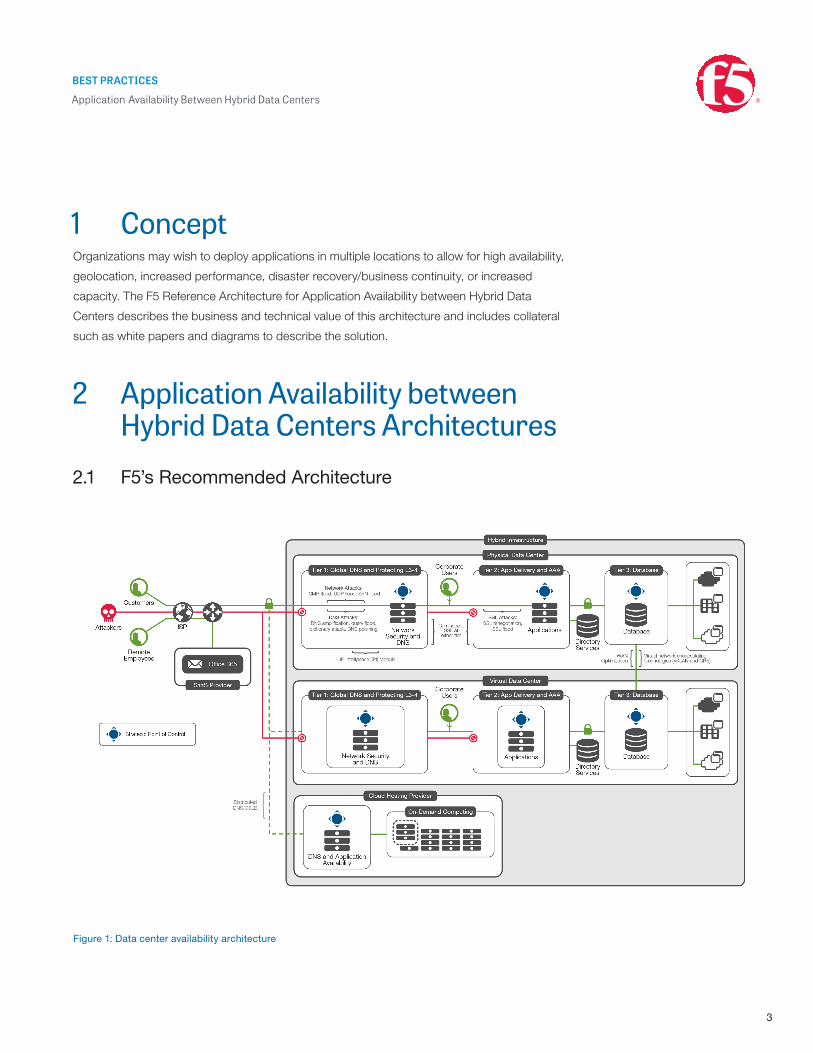
1 ConceptOrganizations may wish to deploy applications in multiple locations to allow for high availability,
geolocation, increased performance, disaster recovery/business continuity, or increased
capacity. The F5 Reference Architecture for Application Availability between Hybrid Data
Centers describes the business and technical value of this architecture and includes collateral
such as white papers and diagrams to describe the solution.
2 Application Availability between Hybrid Data Centers Architectures
2.1 F5’s Recommended Architecture
Figure 1: Data center availability architecture

BEST PRACTICES
Application Availability Between Hybrid Data Centers
4
2.1.1 Scope and Prerequisites
This guide is designed to assist data center and network architects to design and deploy a
hybrid infrastructure that enables an application to be distributed across multiple data
centers. Since the term “application” can describe a wide range of protocols, technologies,
and infrastructure designs, this guide focuses on providing sound design principles and
rules rather than detailed configuration steps. Where more implementation-focused
documents are available, this guide provides links to them.
This guide is suitable for use with BIG-IP version 11.4 and beyond and is not dependent on
particular hardware models or virtual appliances being deployed. Where relevant, the
required software module licenses are mentioned in the text.
2.2 Key Components In addition to providing federated access to SaaS services like Microsoft Office365, F5
offers four key services to applications within multiple data center architectures:
Function Description F5 Software Module
Client traffic management between data centers
Performed by DNS, which resolves service names such as www.example.com or smtp.example.com and directs client traffic to a particular data center. Decisions are made based on monitoring the availability and performance of data center resources and client locations.
BIG-IP Global Traffic Manager (GTM)
Client traffic management within data centers
Terminates the client application data connection (such as an HTTP request or SMTP transaction) and applies application services (for example, load balancing, acceleration, or security) before proxying the traffic to application services. Monitors availability of resources and reports to BIG-IP Global Traffic Manager.
BIG-IP Local Traffic Manager (LTM)
Network security for client application traffic
As part of traffic management by BIG-IP Local Traffic Manager and Global Traffic Manager, provides network security and DDoS mitigation services to application and DNS traffic.
BIG-IP Advanced Firewall Manager (AFM)
Replication of application traffic between data centers
Provides an encrypted, accelerated WAN optimization service between data centers to accelerate replication traffic (for storage or databases), improving recovery times and availability of content between locations.
BIG-IP Application Acceleration Manager (AAM)
BEST PRACTICES
Application Availability Between Hybrid Data Centers
5
2.2.1 Protocols and Communications
Only a few communications protocols (beyond those that apply to actual application traffic)
are relevant to this architecture:
Component Explanation
Application traffic Depends on the application; can be IPv4 or IPv6, TCP, UDP, or SCTP.
DNS The protocol used by clients and DNS servers to request and respond to name resolution requests and other name-based queries). Can be TCP or UDP (both supported).
iQuery A TLS encrypted protocol used to report and synchronize configuration between F5 devices. Uses an agent called big3d on each device.
Network Time Protocol (NTP) Used to establish clock synchronization between devices. Essential for configuration synchronization between devices as the configuration with the most recent timestamp is considered the master for distribution.
Syslog Forwards system-level messages to a log collector.
SNMP Used for querying (or reporting) status or performance of F5 devices.
2.3 Traffic Management between Data Centers
2.3.1 The DNS System
Traffic management between data centers is done by DNS. Control of DNS resolution to
direct client traffic to a particular location is robust, simple, and reliable. The DNS protocol is
well understood and does not require advanced networking protocols or cooperation
between Internet service providers, and it can be extremely fine-grained (for example, any
single service name rather than a whole subnet or Internet route can be redirected).
It’s important to understand, however, that the “client”’ in the DNS resolution chain is not
the actual client but the local DNS server that the clients have been configured to use. This
means that geolocation or round trip time measurements that might be used in making a
resolution decision are based on the local DNS server (LDNS). The overall DNS resolution
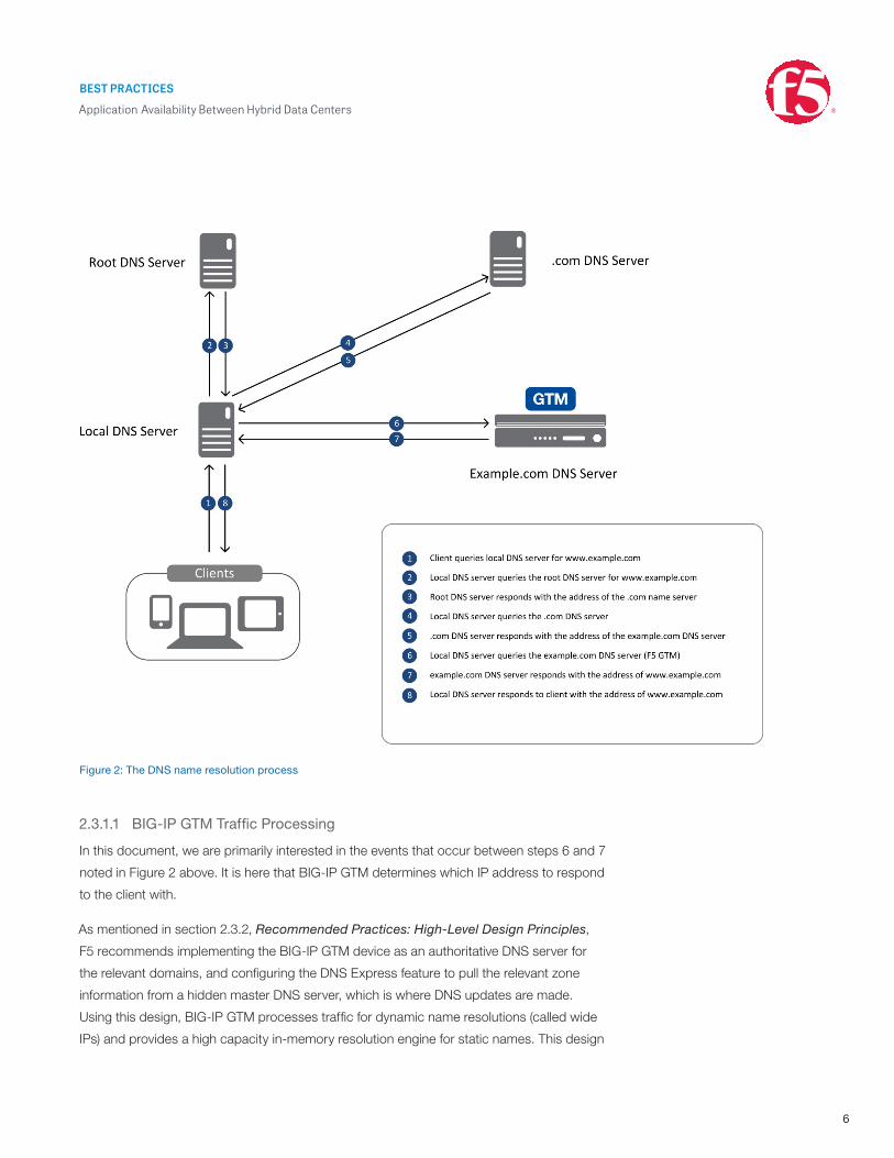
system is shown in figure 2.
BEST PRACTICES
Application Availability Between Hybrid Data Centers
6
Figure 2: The DNS name resolution process
2.3.1.1 BIG-IP GTM Traffic Processing
In this document, we are primarily interested in the events that occur between steps 6 and 7
noted in Figure 2 above. It is here that BIG-IP GTM determines which IP address to respond
to the client with.
As mentioned in section 2.3.2, Recommended Practices: High-Level Design Principles,
F5 recommends implementing the BIG-IP GTM device as an authoritative DNS server for
the relevant domains, and configuring the DNS Express feature to pull the relevant zone
information from a hidden master DNS server, which is where DNS updates are made.
Using this design, BIG-IP GTM processes traffic for dynamic name resolutions (called wide
IPs) and provides a high capacity in-memory resolution engine for static names. This design

BEST PRACTICES
Application Availability Between Hybrid Data Centers
7
also enables the BIG-IP GTM system to provide security and distributed denial of service
(DDoS) mitigation services for an organization’s DNS services.
Figure 3: BIG-IP GTM logic flow
As shown in the Figure 3, steps D and E are responsible for deciding which IP address is
returned to the LDNS server. This decision is determined by a combination of policy and
resource monitoring.
BEST PRACTICES
Application Availability Between Hybrid Data Centers
8
2.3.1.2 Wide IP Policy
The particular policy for a wide IP (that is, the IP address that a service name such as
www.example.com resolves to) can depend on multiple factors that generally fall into one
of three broad categories:
Category Description
Client (LDNS) location Can be determined by using an onboard geolocation database or by testing the connection latency from data centers to the LDNS server
Service availability Determined by monitoring the application and network link availability at the data centers
Service capacity Determined by monitoring link capacity, backend server availability, or service response times at the data centers
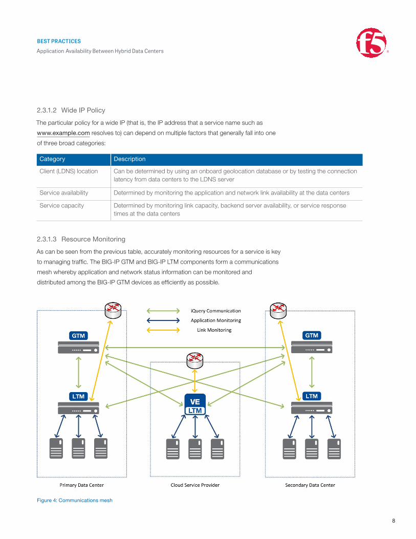
2.3.1.3 Resource Monitoring
As can be seen from the previous table, accurately monitoring resources for a service is key
to managing traffic. The BIG-IP GTM and BIG-IP LTM components form a communications
mesh whereby application and network status information can be monitored and
distributed among the BIG-IP GTM devices as efficiently as possible.
Figure 4: Communications mesh
BEST PRACTICES
Application Availability Between Hybrid Data Centers
9
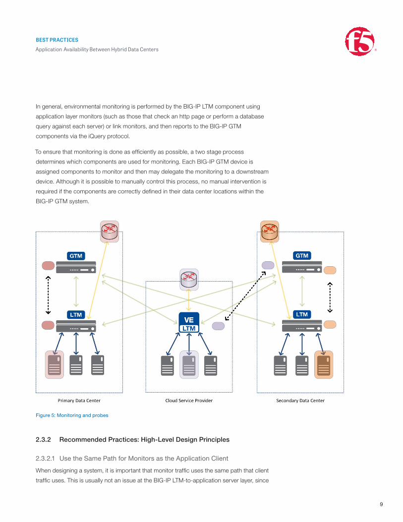
In general, environmental monitoring is performed by the BIG-IP LTM component using
application layer monitors (such as those that check an http page or perform a database
query against each server) or link monitors, and then reports to the BIG-IP GTM
components via the iQuery protocol.
To ensure that monitoring is done as efficiently as possible, a two stage process
determines which components are used for monitoring. Each BIG-IP GTM device is
assigned components to monitor and then may delegate the monitoring to a downstream
device. Although it is possible to manually control this process, no manual intervention is
required if the components are correctly defined in their data center locations within the
BIG-IP GTM system.
Figure 5: Monitoring and probes
2.3.2 Recommended Practices: High-Level Design Principles
2.3.2.1 Use the Same Path for Monitors as the Application Client
When designing a system, it is important that monitor traffic uses the same path that client
traffic uses. This is usually not an issue at the BIG-IP LTM-to-application server layer, since

BEST PRACTICES
Application Availability Between Hybrid Data Centers
10
in almost all correctly configured systems the monitor traffic will follow the same path as the
proxied traffic. When this monitor information is communicated “upstream” to the BIG-IP
GTM components, the path ideally should be the same as the client traffic inbound to the
data center. Should the link between the BIG-IP GTM and the BIG-IP LTM components fail,
BIG-IP GTM marks the data center “down” and directs client traffic to the other data centers
that are marked “available.” Use of an alternate link (for example, a “private” dedicated link)
might cause a data center to be marked “up” when, in fact, it is unavailable in terms of client
traffic access. This should be the case for the path from the BIG-IP LTM device to all of the
available BIG-IP GTM devices.
2.3.2.2 Use the Same Path for Synchronization as the DNS Client
As is the case with monitor traffic, it is important that synchronization traffic between BIG-IP
GTM devices follows a similar path to data access. Should the client access path to a
BIG-IP GTM device go down, it is a probable indicator of loss of traffic to the data center.
When BIG-IP GTM devices communicate over private links, there are similar situations in
which a data center may be marked “up” when it is actually unavailable. Using the same
path for synchronization traffic and client traffic ensures that the BIG-IP GTM directs traffic
to a site that is available to the client.
2.3.2.3 Use BIG-IP GTM as the authoritative DNS Server with DNS Express
The design shown in Figure 3 allows for DNS management tasks to be performed using the
DNS tools and servers an organization chooses and for all external DNS requests to be
handled by BIG-IP GTM. The DNS Express feature in BIG-IP GTM is a high performance,
in-memory DNS server that, depending on hardware, can scale to hundreds of thousands
of DNS queries per second. This allows for a combination of DNS features like Global
Server Load Balancing and high performance DNS resolution. For more information, see
the F5 DNS Reference Architecture.
2.3.2.4 Avoid Using Alias Addresses
In older architecture designs, it was common to place network firewalls in front of the
application delivery devices that were managing the traffic. These firewalls would frequently
perform network address translations (NAT) for the IP addresses behind them. With the
advent of the ICSA-certified BIG-IP platform and the BIG-IP Advanced Firewall Manager,
a separate firewall is not necessary in most data centers. This is because BIG-IP solutions
provide excellent levels of protection for application traffic. They also remove the necessity
to map “internal” addresses (as reported by the BIG-IP device) to public addresses, which
BIG-IP GTM uses to respond to the client. When application traffic is sent to an address
that has a NAT applied, additional configuration on the BIG-IP GTM is required.
BEST PRACTICES
Application Availability Between Hybrid Data Centers
11
2.3.2.5 Avoid Excessive Monitoring
When all members of a BIG-IP GTM pool are BIG-IP LTM virtual servers, it isn’t necessary
to associate a monitor with the pool. The health monitors on BIG-IP LTM provide the status
for those virtual servers, and the BIG-IP LTM system’s big3d agent uses iQuery to report the
BIG-IP LTM virtual server status to the BIG-IP GTM system. If you apply monitors to both
the BIG-IP LTM virtual server object and its corresponding BIG-IP GTM virtual server object,
the system runs both monitors. Using this configuration may cause the system to generate
excessive monitor traffic, potentially overwhelming the resources that the system is
monitoring as well as the monitoring agents. When this behavior occurs, some monitors
may generate false negatives, and objects may be incorrectly marked “down.”
2.3.2.6 Use NTP
BIG-IP GTM devices are designed to be linked to a GTM synchronization group. This
enables both persistence records and configuration updates to be distributed among the
group. The “master” configuration that is distributed is determined by change time, so time
synchronization between devices is essential. This is done by configuring NTP servers on
each BIG-IP GTM device.
2.4 Traffic Management within Data CentersWhen a client receives an address resolution for a service name, it sends data to the
application. The IP address supplied is that of a virtual server advertised by a BIG-IP device
in the relevant data center. BIG-IP LTM is responsible for providing a full proxy of the
application data (and inserting application services supplied by other BIG-IP modules) to a
backend server, wherever that server might be. That server is selected based on the
specified load balancing algorithm and the current status of application health monitors.
These monitors also communicate the overall status of the service to BIG-IP GTM to aid in
data center selection.
A guide to the various traffic management capabilities and services offered by the BIG-IP
platform is given in the Application Services Reference Architecture.
2.4.1 Using Priority Pools to Maintain Application Availability
Although the general use of a BIG-IP LTM system to provide application services is well
covered in F5 documentation and the Reference Architecture above, the use of priority
pools can be valuable when multiple data centers are interconnected by high speed links.
Priority pools allow application traffic to be serviced by one data center, even when no
application servers are available to serve the application traffic. Priority pools also allow for

BEST PRACTICES
Application Availability Between Hybrid Data Centers
12
BIG-IP devices to prefer local application servers but to proxy traffic to an alternate pool of
servers if the local pool becomes unavailable or is overloaded. This feature can be useful in
both active-active and active-passive application designs. (The distribution model is
determined by service name, not at a global level. For example, www.example.com might
be distributed across multiple data centers while mail.example.com might only be active in
one). The traffic between the two data centers can take any routable path, but F5
recommended practice is to deploy BIG-IP Application Acceleration Manager (AAM) to
manage this inter-site traffic, along with any required storage or application data replication
(see section 2.5). BIG-IP AAM can significantly accelerate traffic and also encrypt and
tunnel it, should this be required.
Figure 6: The use of priority pools
Priority pools are especially useful when an application is not honoring the short DNS TTL
values that BIG-IP GTM sets for managed wide IPs. It is also useful for situations in which a
BEST PRACTICES
Application Availability Between Hybrid Data Centers
13
temporary failure of an application stack (such as during an upgrade) does not warrant a full
data center failover. Obviously, the supporting infrastructure components (databases, other
servers, etc.) need to be accessible to the application servers at the alternate site.
The use of priority activation for pools is comprehensively described in the F5 Documentation.
2.5 Replication of Application Traffic between Data Centers
The BIG-IP GTM solution described in section 2.3 delivers a robust and simple method for
providing application availability between data centers. Most applications, however, consist
of more than a client and autonomous server. Common application architectures involve
database server and application servers supporting frontend application servers (for
example, the three-tier design that has been common for many years). To ensure
application availability across data centers, high speed and secure data replication between
sites is often required. BIG-IP AAM provides accelerated, encrypted tunnels between sites
to improve the replication of database and storage traffic.
Generic installation and configuration information for BIG-IP AAM can be found at the
F5 Support website, and in the Data Replication iApp Deployment Guide.
BIG-IP AAM provides three classes of acceleration functions:
• TCP optimization
• Data compression
• Data deduplication
Each of these functions can be tuned for a particular traffic type or are self-tuning and
self-optimizing. Where quick start configurations exist, these settings have been pre-
optimized for that particular application traffic.
2.5.1 Recommended Design Practices
For most F5 products, there are multiple design options for implementation, and BIG-IP
AAM can generally be configured to work in almost any network design. There are, however,
some generic recommended practices that, if incorporated into an architecture design, will
result in a smoother and more supportable deployment.

BEST PRACTICES
Application Availability Between Hybrid Data Centers
14
2.5.1.1 Use a Simple Routed Design
Network acceleration using BIG-IP AAM can be configured in three different types of
network designs:
• One-arm using WCCPv2
• Bridged
• Routed
Of these three, creating a simple layer 3 routed design is the easiest method for directing
application traffic via BIG-IP AAM. In this mode, the BIG-IP devices have separate LAN and
WAN IP addresses, with the LAN-side IPs being the next hop for traffic routed between
sites. A routed configuration is easy to troubleshoot and support. The only potential
drawback is the need for high availability in routed mode.
2.5.1.2 Understand your Traffic, or Use a Preconfigured Profile
The preconfigured application profiles in the Replication iApp offer recommended
configurations for a number of applications (see section 2.5.1.4). For certain application
traffic, understanding the nature of the data can help in selecting the correct settings. Most
data will benefit from compression, but traffic that is pre-encrypted, for example, will not
respond well to compression. Where possible, it is recommended to disable encryption and
compression of application data at the application layer and rely on the compression and
encryption services that BIG-IP AAM provides. Data deduplication may not yield good
results for some data types, but will greatly enhance others. The WAN Optimization
dashboard can provide a useful insight into the effectiveness of the chosen techniques;
then adjustments can be made to traffic optimization settings and the results compared.
2.5.1.3 Get Traffic Passing before Configuring BIG-IP AAM
To aid troubleshooting and streamline the deployment process, ensure that traffic passes
correctly through the BIG-IP infrastructure before configuring WAN optimization. The
simplest configuration is to create forwarding virtual servers on each of the BIG-IP devices
that will form the accelerated connection.

BEST PRACTICES
Application Availability Between Hybrid Data Centers
15
Figure 7: Basic routed configuration
These virtual servers essentially act as routing interfaces and will route traffic based on the
routing table on the BIG-IP (this also relies on correct client and server routing configuration).
The forwarding servers should be enabled only on the networks that will receive client traffic
and should be restricted to accepting traffic from and to the relevant networks, unless a
truly open router is required.
An alternative configuration is to handle traffic from the client side by a standard BIG-IP
virtual server using the target server as a pool member.
Figure 8: Routed configuration with standard virtual server
In this configuration, all data is sent unencrypted and on the native ports that the application
uses.
The next step is to configure the local endpoints on the BIG-IP devices. This will establish
a WAN-facing endpoint for the accelerated tunnel, called an iSession.
Figure 9: iSession endpoints
At this point, it is important to check the connectivity and setup of the BIG-IP AAM
connection using the diagnostic tests in the configuration guide.
BEST PRACTICES
Application Availability Between Hybrid Data Centers
16
2.5.1.4 Use the Replication iApp to Configure Data Replication Services
The Data replication iApp will create the necessary components on the client side BIG-IP
device to accelerate traffic for a number of data replication protocols:
• Dell EqualLogic
• EMC SRDF
• Hitachi TrueCopy
• Microsoft SQL Server
• Microsoft Exchange DAG
• NetApp FlexCache
• NetApp SnapVault and SnapMirror
• Oracle Streams
• Oracle GoldenGate
• Oracle Data Guard
In addition, the data replication iApp can also be used to accelerate most replication traffic,
because the iApp has an option for custom settings. The iApp creates create a number of
additional BIG-IP objects:
Object Purpose
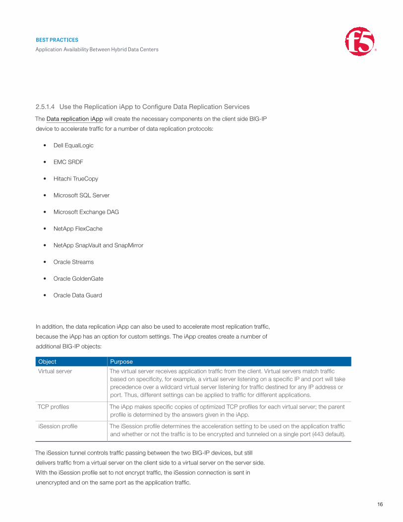
Virtual server The virtual server receives application traffic from the client. Virtual servers match traffic based on specificity, for example, a virtual server listening on a specific IP and port will take precedence over a wildcard virtual server listening for traffic destined for any IP address or port. Thus, different settings can be applied to traffic for different applications.
TCP profiles The iApp makes specific copies of optimized TCP profiles for each virtual server; the parent profile is determined by the answers given in the iApp.
iSession profile The iSession profile determines the acceleration setting to be used on the application traffic and whether or not the traffic is to be encrypted and tunneled on a single port (443 default).
The iSession tunnel controls traffic passing between the two BIG-IP devices, but still
delivers traffic from a virtual server on the client side to a virtual server on the server side.
With the iSession profile set to not encrypt traffic, the iSession connection is sent in
unencrypted and on the same port as the application traffic.

BEST PRACTICES
Application Availability Between Hybrid Data Centers
17
Figure 10: iSession (unencrypted)
If the iSession profile for the virtual server is set to encrypt, then SSL is used to encrypt and
tunnel the traffic between devices.
Figure 11: iSession (encrypted)
Since each virtual server can have its own iSession profile, the appropriate levels of
compression, deduplication, and encryption can be determined on an application by
application basis.
iSession encryption uses the same SSL profile objects that the BIG-IP device uses for any
outbound encrypted traffic. For testing and proof of concept, then the default serverssl
profile can be used, but for production traffic, it is recommended to follow the guidelines for
securing iSession traffic.
Once configured, traffic that hits the virtual server created by the iApp is optimized by the
iSession tunnel between the two devices and should be significantly accelerated. Tests
using Oracle database replication technology showed up to a 23x improvement in transfer
speeds.
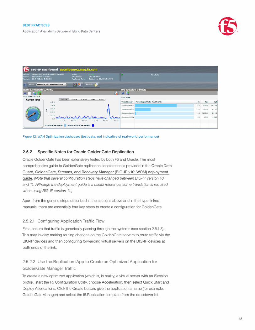
2.5.1.5 Use the WAN Optimization Dashboard to Monitor Results
The WAN optimization dashboard provides a real-time overview of WAN optimization
metrics and is useful in checking that traffic is actually being optimized. The dashboard
provides information on each iSession-enabled virtual server and details of throughput and
compression ratios.
BEST PRACTICES
Application Availability Between Hybrid Data Centers
18
Figure 12: WAN Optimization dashboard (test data: not indicative of real-world performance)
2.5.2 Specific Notes for Oracle GoldenGate Replication
Oracle GoldenGate has been extensively tested by both F5 and Oracle. The most
comprehensive guide to GoldenGate replication acceleration is provided in the Oracle Data
Guard, GoldenGate, Streams, and Recovery Manager (BIG-IP v10: WOM) deployment
guide. (Note that several configuration steps have changed between BIG-IP version 10
and 11. Although the deployment guide is a useful reference, some translation is required
when using BIG-IP version 11.)
Apart from the generic steps described in the sections above and in the hyperlinked
manuals, there are essentially four key steps to create a configuration for GoldenGate:
2.5.2.1 Configuring Application Traffic Flow
First, ensure that traffic is generically passing through the systems (see section 2.5.1.3).
This may involve making routing changes on the GoldenGate servers to route traffic via the
BIG-IP devices and then configuring forwarding virtual servers on the BIG-IP devices at
both ends of the link.
2.5.2.2 Use the Replication iApp to Create an Optimized Application for
GoldenGate Manager Traffic
To create a new optimized application (which is, in reality, a virtual server with an iSession
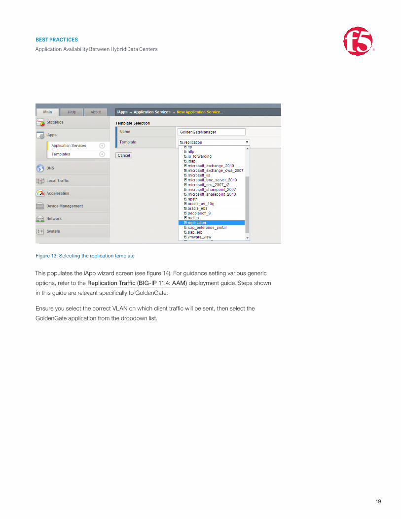
profile), start the F5 Configuration Utility, choose Acceleration, then select Quick Start and
Deploy Applications. Click the Create button, give the application a name (for example,
GoldenGateManager) and select the f5.Replication template from the dropdown list.
BEST PRACTICES
Application Availability Between Hybrid Data Centers
19
Figure 13: Selecting the replication template
This populates the iApp wizard screen (see figure 14). For guidance setting various generic
options, refer to the Replication Traffic (BIG-IP 11.4: AAM) deployment guide. Steps shown
in this guide are relevant specifically to GoldenGate.
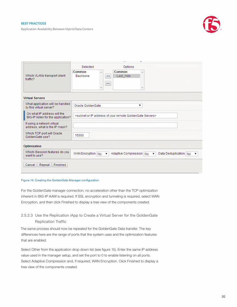
Ensure you select the correct VLAN on which client traffic will be sent, then select the
GoldenGate application from the dropdown list.
BEST PRACTICES
Application Availability Between Hybrid Data Centers
20
Figure 14: Creating the GoldenGate Manager configuration
For the GoldenGate manager connection, no acceleration other than the TCP optimization
inherent in BIG-IP AAM is required. If SSL encryption and tunneling is required, select WAN
Encryption, and then click Finished to display a tree view of the components created.
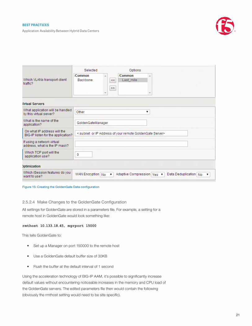
2.5.2.3 Use the Replication iApp to Create a Virtual Server for the GoldenGate
Replication Traffic
The same process should now be repeated for the GoldenGate Data transfer. The key
differences here are the range of ports that the system uses and the optimization features
that are enabled.
Select Other from the application drop down list (see figure 15). Enter the same IP address
value used in the manager setup, and set the port to 0 to enable listening on all ports.
Select Adaptive Compression and, if required, WAN Encryption. Click Finished to display a
tree view of the components created.
BEST PRACTICES
Application Availability Between Hybrid Data Centers
21
Figure 15: Creating the GoldenGate Data configuration
2.5.2.4 Make Changes to the GoldenGate Configuration
All settings for GoldenGate are stored in a parameters file. For example, a setting for a
remote host in GoldenGate would look something like:
rmthost 10.133.18.45, mgrport 15000
This tells GoldenGate to:
• Set up a Manager on port 150000 to the remote host
• Use a GoldenGate default buffer size of 30KB
• Flush the buffer at the default interval of 1 second
Using the acceleration technology of BIG-IP AAM, it’s possible to significantly increase
default values without encountering noticeable increases in the memory and CPU load of
the GoldenGate servers. The edited parameters file then would contain the following
(obviously the rmthost setting would need to be site specific).
BEST PRACTICES
Application Availability Between Hybrid Data Centers
F5 Networks, Inc. 401 Elliott Avenue West, Seattle, WA 98119 888-882-4447 www.f5.com
Europe/Middle-East/[email protected]
Japan [email protected]
©2015 F5 Networks, Inc. All rights reserved. F5, F5 Networks, and the F5 logo are trademarks of F5 Networks, Inc. in the U.S. and in certain other countries. Other F5 trademarks are identified at f5.com. Any other products, services, or company names referenced herein may be trademarks of their respective owners with no endorsement or affiliation, express or implied, claimed by F5. 0215 BESTP-CLOUD-37363
rmthost 10.133.18.45, mgrport 15000, tcpbufsize 1000000, tcpflushbytes
1000000
It is not necessary to use GoldenGate’s bundled compression and encryption since these
are built into BIG-IP AAM.
3 ConclusionThe F5 Reference Architecture for Application Availability between Hybrid Data Centers
offers a simple and robust design for managing traffic into, within, and between data
centers. The components in the design can be deployed individually, or together—and
combined with other reference architectures such as DDoS Mitigation.
While every situation is different, using the design principles contained in this guide will enable
architects and engineers to create an infrastructure that is stable and easy to manage.