Embed Size (px)
Citation preview
APPENDIX CWORST-CASE CONSEQUENCE ANALYSIS

This page intentionally left blank.
WORST-CASE CONSEQUENCE ANALYSIS FOR THE TESORO LOS ANGELES REFINERY
Prepared For
Environmental Audit, Inc. 1000-A Ortega Way
Placentia, CA 92670-7125
Prepared By
Quest Consultants Inc.® 908 26th Avenue N.W. Norman, OK 73069
Telephone: 405-329-7475 Fax: 405-329-7734
6950-CAS01-RevF1 April 23, 2015
Appendix C
C-1

This page intentionally left blank.
Appendix C
C-2
Worst-Case Consequence Analysis for the Tesoro Los Angeles Refinery 6950-CAS01-RevF1 Page i
April 23, 2015 QUEST
WORST-CASE CONSEQUENCE ANALYSIS FOR THE TESORO LOS ANGELES REFINERY
Table of Contents
Page 1.0 INTRODUCTION ........................................................................................................................... 1 2.0 OVERVIEW OF TESORO LOS ANGELES REFINERY ............................................................. 2
2.1 Facility Location ................................................................................................................. 2 2.1.1 Wilmington Operations .......................................................................................... 2
2.1.1.1 FCCU Shutdown ....................................................................................... 2 2.1.1.2 HCU Modification .................................................................................... 2 2.1.1.3 DCU Fresh Feed Heater (H-100) .............................................................. 2 2.1.1.4 Propane Sales Treating Unit (PSTU) ........................................................ 2 2.1.1.5 CRU3 Modification .................................................................................. 2 2.1.1.6 HTU-1 and 2 Modifications (HTU-1/2) ................................................... 6 2.1.1.7 HTU-4 Modification ................................................................................. 6 2.1.1.8 New Sulfuric Acid Regeneration Plant ..................................................... 6 2.1.1.9 Wilmington Storage Tanks ....................................................................... 6
2.1.2 Carson Operations.................................................................................................. 6 2.1.2.1 No. 51 Vacuum Unit Modifications ......................................................... 6 2.1.2.2 New Wet Jet Treater ................................................................................. 6 2.1.2.3 HCU Modification .................................................................................... 6 2.1.2.4 LHU Modifications ................................................................................... 7 2.1.2.5 Naphtha HDS Unit Modification .............................................................. 7 2.1.2.6 Naphtha Isomerization Unit Modifications .............................................. 7 2.1.2.7 Alkylation Modification ........................................................................... 7 2.1.2.8 Mid-Barrel Distillate Treater Modifications ............................................. 7 2.1.2.9 Steam System Balance Modification ........................................................ 7 2.1.2.10 Carson Storage Tanks ............................................................................... 7
2.1.3 Modifications to Supporting Equipment ................................................................ 8 2.1.3.1 Interconnecting Pipeway........................................................................... 8 2.1.3.2 Liquid Petroleum Gas (LPG) Rail Loading/Unloading ............................ 8
3.0 MODELING METHODOLOGY .................................................................................................... 9
3.1 CANARY Consequence Analysis Models .......................................................................... 9 3.2 The QMEFS Model for Vapor Cloud Explosions .............................................................. 9 3.3 Hazards Identification and Modeling Endpoints .............................................................. 10 3.4 Weather Conditions .......................................................................................................... 12
4.0 IMPLEMENTATION OF WORST-CASE
CONSEQUENCE MODELING METHODOLOGY .................................................................... 13 4.1 Accident Selection ............................................................................................................ 13 4.2 Releases Resulting in the Largest Downwind Hazard Zones ........................................... 13 4.3 Worst-Case Consequences ................................................................................................ 13
Appendix C
C-3
Worst-Case Consequence Analysis for the Tesoro Los Angeles Refinery 6950-CAS01-RevF1 Page ii
April 23, 2015 QUEST
Table of Contents (continued)
Page
4.3.1 Flash Fires ............................................................................................................ 13 4.3.2 Fire Radiation ...................................................................................................... 17 4.3.3 Toxic Vapor Clouds ............................................................................................. 17 4.3.4 Vapor Cloud Explosions (VCE) .......................................................................... 17
4.4 Summary of Maximum Vulnerability Zones .................................................................... 17 5.0 CONCLUSIONS ........................................................................................................................... 23 6.0 REFERENCES .............................................................................................................................. 24 APPENDIX A RESUMES ...................................................................................................................... A-1
Appendix C
C-4
Worst-Case Consequence Analysis for the Tesoro Los Angeles Refinery 6950-CAS01-RevF1 Page 1
April 23, 2015 QUEST
WORST-CASE CONSEQUENCE ANALYSIS FOR THE TESORO LOS ANGELES REFINERY
1.0 INTRODUCTION Quest Consultants Inc.® was retained by Environmental Audit, Inc. and Tesoro Refining & Marketing Company LLC (Tesoro) to perform a worst-case consequence analysis on the proposed Los Angeles Refinery changes. The primary authors of this report are John B. Cornwell and David W. Johnson, and their resumes are listed in Appendix A. The objective of the study was to compute the potential increase or decrease in hazards to the public due to the proposed changes to the facility. The study was divided into three tasks. Task 1. Determine the maximum credible potential releases, and their consequences, for existing process
units, transfer systems, and storage areas. Task 2. Determine the maximum credible potential releases, and their consequences, for the
modifications to the facility which have been proposed by Tesoro. Task 3. Determine whether the consequences associated with the proposed modifications generate
potential hazards that are larger or smaller than the potential hazards which currently exist. Potential hazards from the existing and proposed equipment are associated with accidental releases of toxic and flammable materials. Hazardous events associated with these types of releases include toxic vapor clouds, flash fires, torch fires, pool fires, and vapor cloud explosions. For each type of hazard identified (toxic, radiant, overpressure), maximum distances to potentially injurious levels (vulnerability/hazard zones) are determined. The hazard levels used are those that have been developed by the U.S. Environmental Protection Agency (EPA) and American Industrial Hygiene Association (AIHA) for risk management purposes.
Appendix C
C-5
Worst-Case Consequence Analysis for the Tesoro Los Angeles Refinery 6950-CAS01-RevF1 Page 2
April 23, 2015 QUEST
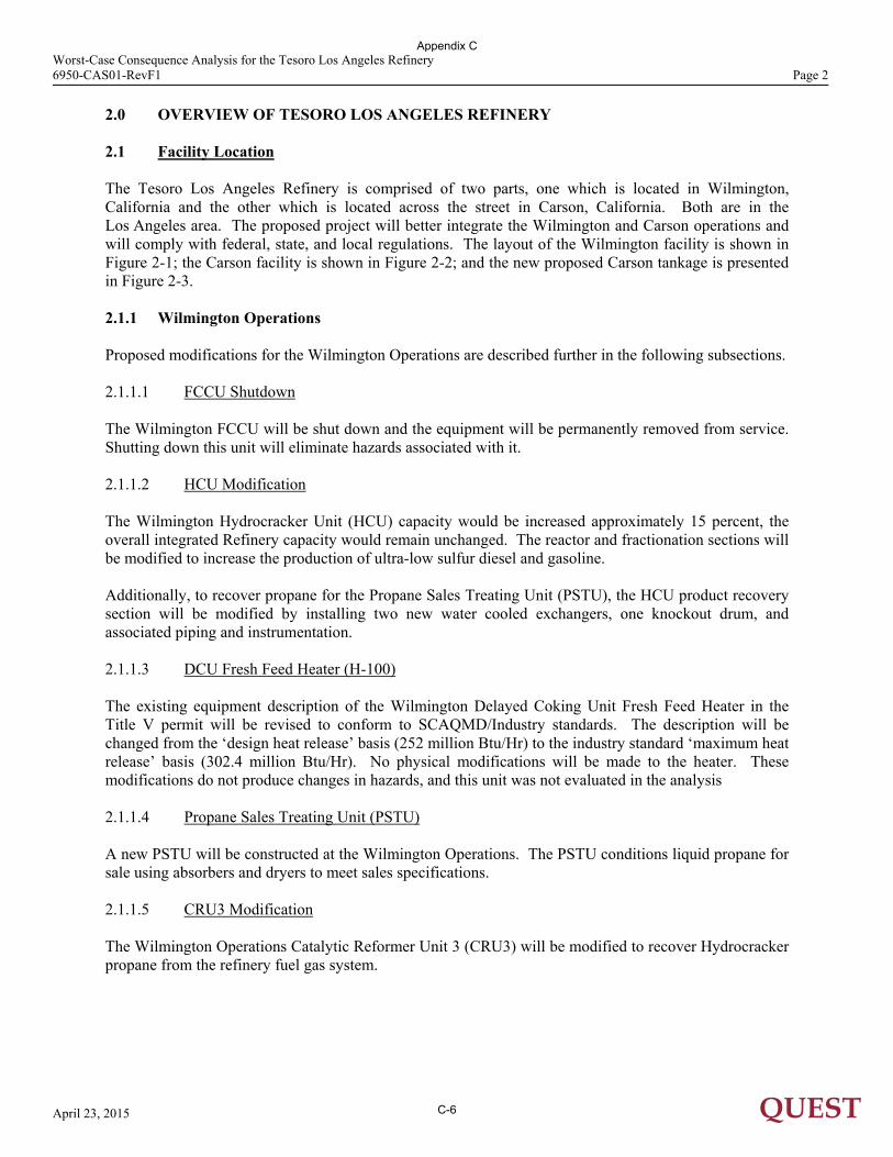
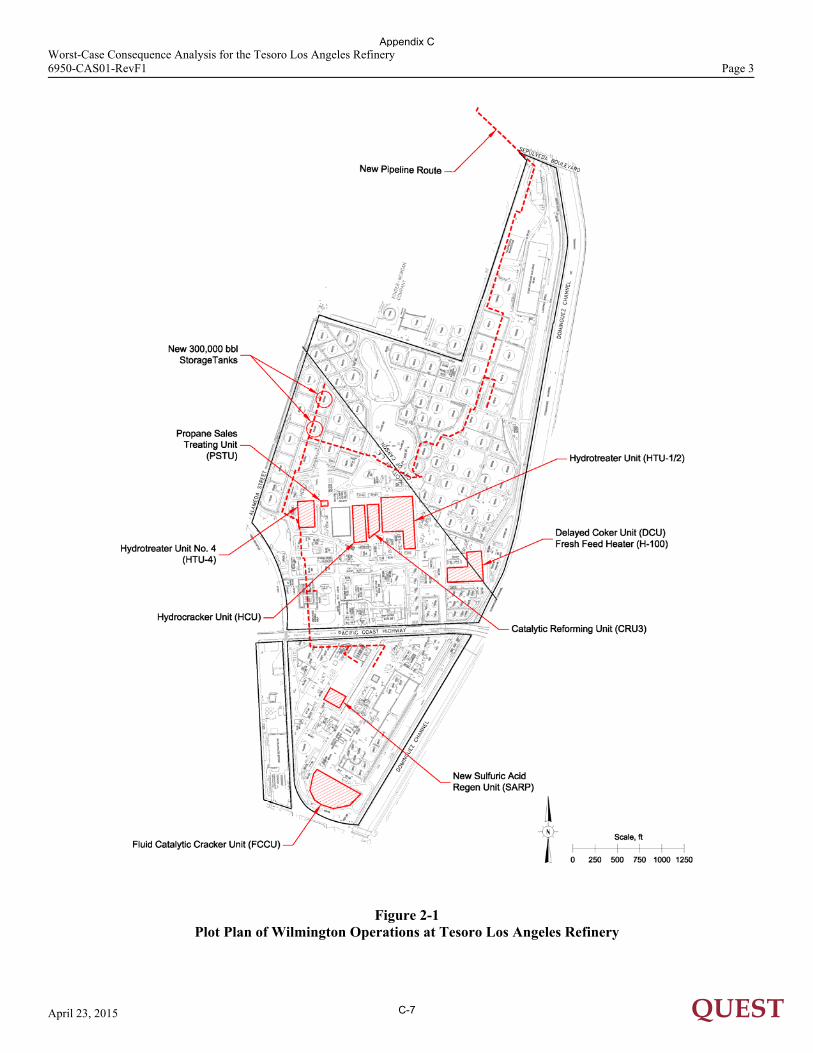
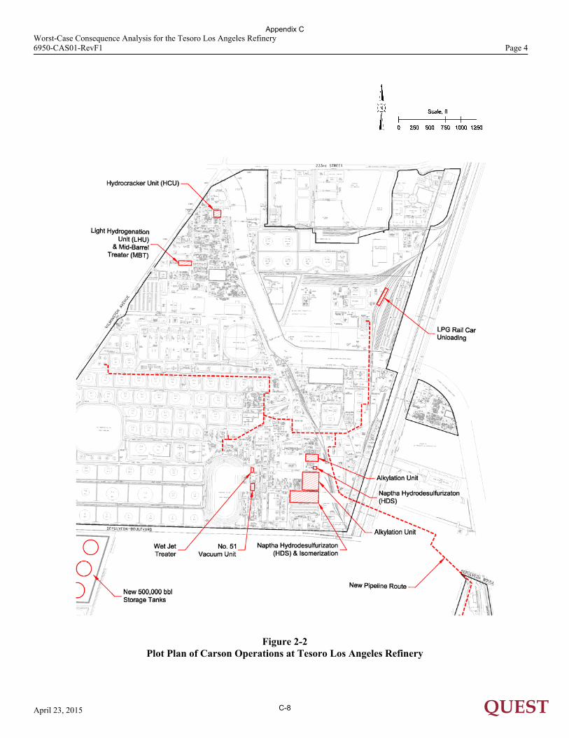
2.0 OVERVIEW OF TESORO LOS ANGELES REFINERY 2.1 Facility Location The Tesoro Los Angeles Refinery is comprised of two parts, one which is located in Wilmington, California and the other which is located across the street in Carson, California. Both are in the Los Angeles area. The proposed project will better integrate the Wilmington and Carson operations and will comply with federal, state, and local regulations. The layout of the Wilmington facility is shown in Figure 2-1; the Carson facility is shown in Figure 2-2; and the new proposed Carson tankage is presented in Figure 2-3. 2.1.1 Wilmington Operations Proposed modifications for the Wilmington Operations are described further in the following subsections. 2.1.1.1 FCCU Shutdown The Wilmington FCCU will be shut down and the equipment will be permanently removed from service. Shutting down this unit will eliminate hazards associated with it. 2.1.1.2 HCU Modification The Wilmington Hydrocracker Unit (HCU) capacity would be increased approximately 15 percent, the overall integrated Refinery capacity would remain unchanged. The reactor and fractionation sections will be modified to increase the production of ultra-low sulfur diesel and gasoline. Additionally, to recover propane for the Propane Sales Treating Unit (PSTU), the HCU product recovery section will be modified by installing two new water cooled exchangers, one knockout drum, and associated piping and instrumentation. 2.1.1.3 DCU Fresh Feed Heater (H-100) The existing equipment description of the Wilmington Delayed Coking Unit Fresh Feed Heater in the Title V permit will be revised to conform to SCAQMD/Industry standards. The description will be changed from the ‘design heat release’ basis (252 million Btu/Hr) to the industry standard ‘maximum heat release’ basis (302.4 million Btu/Hr). No physical modifications will be made to the heater. These modifications do not produce changes in hazards, and this unit was not evaluated in the analysis 2.1.1.4 Propane Sales Treating Unit (PSTU) A new PSTU will be constructed at the Wilmington Operations. The PSTU conditions liquid propane for sale using absorbers and dryers to meet sales specifications. 2.1.1.5 CRU3 Modification The Wilmington Operations Catalytic Reformer Unit 3 (CRU3) will be modified to recover Hydrocracker propane from the refinery fuel gas system.
Appendix C
C-6
Worst-Case Consequence Analysis for the Tesoro Los Angeles Refinery 6950-CAS01-RevF1 Page 3
April 23, 2015 QUEST
Figure 2-1
Plot Plan of Wilmington Operations at Tesoro Los Angeles Refinery
Appendix C
C-7
Worst-Case Consequence Analysis for the Tesoro Los Angeles Refinery 6950-CAS01-RevF1 Page 4
April 23, 2015 QUEST
Figure 2-2
Plot Plan of Carson Operations at Tesoro Los Angeles Refinery
Appendix C
C-8
Worst-Case Consequence Analysis for the Tesoro Los Angeles Refinery 6950-CAS01-RevF1 Page 5
April 23, 2015 QUEST
Figure 2-3
Plot Plan of New 500,000 bbl. Storage Tanks
Appendix C
C-9
Worst-Case Consequence Analysis for the Tesoro Los Angeles Refinery 6950-CAS01-RevF1 Page 6
April 23, 2015 QUEST
2.1.1.6 HTU-1 and 2 Modifications (HTU-1/2) The Wilmington Operations Hydrotreater Unit 1 (HTU-1) will be modified to hydrotreat approximately 20,000 BPD of FCCU gasoline to comply with the federally mandated Tier 3 gasoline specifications. HTU-2 feed will be separated from HTU-1 feed. 2.1.1.7 HTU-4 Modification The Wilmington Operations Hydrotreater Unit No. 4 (HTU-4) will be modified to fully utilize the existing hydrotreating capacity to produce ultra-low sulfur diesel, to recover jet fuel, and to reduce energy consumption. These modifications do not produce changes in hazards, and this unit was not evaluated in the analysis. 2.1.1.8 New Sulfuric Acid Regeneration Plant The proposed new Sulfuric Acid Regeneration Plant (SARP) will be constructed in the Wilmington operations area and will remove impurities from and recycle the Wilmington and Carson Operations spent sulfuric acid to produce fresh sulfuric acid. 2.1.1.9 Wilmington Storage Tanks Two new 300,000 barrel internal floating roof storage tanks (Tanks 300035 and 300036) will replace two existing 80,000 barrel fixed-roof storage tanks (Tanks 80035 and 80036) in the north tank area of Wilmington Operations. Tanks 80038, 80044, 80060, 80067, 80074, 80211, 80215, and 80217 will have increased utilization, increased throughput, or conversion to internal floating roofs. None of these changes will affect the hazard zone associated with each tank. 2.1.2 Carson Operations Proposed modifications to the Carson Operations are described in the following subsections. 2.1.2.1 No. 51 Vacuum Unit Modifications The No. 51 Vacuum Unit (51VAC) will be modified to provide the flexibility to increase diesel production by decreasing vacuum gas oil production by approximately 8,000 BPD. 2.1.2.2 New Wet Jet Treater One new 50,000 BPD Wet Jet Treater (WetJet) will be installed at Carson Operations to remove mercaptans and to reduce the total acid number (TAN), or organic acid content, in jet fuel. 2.1.2.3 HCU Modification The Carson Operations Hydrocracker (HCU) will be modified to add flexibility of running the distillate recovered from the No. 51 Vacuum and the Fluid Feed Hydrodesulfurization (FFHDS) Units. The HCU capacity will be increased by 10 percent.
Appendix C
C-10
Worst-Case Consequence Analysis for the Tesoro Los Angeles Refinery 6950-CAS01-RevF1 Page 7
April 23, 2015 QUEST
2.1.2.4 LHU Modifications The Carson Operations Light Hydrotreating Unit (LHU) will be modified to more effectively remove sulfur from FCCU gasoline to comply with the federally mandated Tier 3 gasoline sulfur specification. 2.1.2.5 Naphtha HDS Unit Modification The Carson Operations Naphtha Hydrodesulfurization (Naptha HDS) unit will be modified with the installation of new equipment to allow removal of contaminants from unit feed and sulfur from pentanes. 2.1.2.6 Naphtha Isomerization Unit Modifications The Carson Operations Naphtha Isomerization Unit (ISOM) will be modified to recover propane and heavier material from the Unit off-gas. 2.1.2.7 Alkylation Modification The Carson Operations Alkylation Unit (ALKY) will be modified to separate amylenes to feed the Carson Operations Alkylation Unit. 2.1.2.8 Mid-Barrel Distillate Treater Modifications The existing Mid Barrel Distillate Treater (MBT) will be modified to remove sulfur from heavy FCCU naptha as well as to continue to treat straight run diesel. 2.1.2.9 Steam System Balance Modification The Carson Operations steam system balance will be impacted due to Tier 3 conformance and the shifting of distillates draws. Implementing the projects described above will result in an increased steam demand at the Carson Operations. The increased steam demand will be met by a combination of; installing waste heat steam generators, generating more steam from the existing Cogen Units and reducing steam demand from existing steam turbines. 2.1.2.10 Carson Storage Tanks Up to six new 500,000 barrel floating roof crude oil storage tanks will be constructed adjacent to the Carson Crude Terminal. Tanks 14, 31, 62, 63, 64, 502, and 959 will have increased utilization. This will not affect the hazard zones associated with each tank.
Appendix C
C-11
Worst-Case Consequence Analysis for the Tesoro Los Angeles Refinery 6950-CAS01-RevF1 Page 8
April 23, 2015 QUEST
2.1.3 Modifications to Supporting Equipment 2.1.3.1 Interconnecting Pipeway The proposed project will require an interconnecting pipeway between the Wilmington and Carson Operations. The pipeway will be comprised of one pipe bundle of up to 15 pipelines ranging from 4 inches to 12 inches in diameter. The pipeway is proposed to exit the Carson Operations and be routed underneath S. Alameda Street to land near the Tesoro Coke Barn. The pipeway would then be routed underneath E. Sepulveda Boulevard to connect to the Wilmington Operations. The pipeway would then be routed above ground on pipe racks or ground level pipe supports into the respective product and supply manifolds within the Refinery. 2.1.3.2 Liquid Petroleum Gas (LPG) Rail Loading/Unloading The LPG Rail Car Unloading facilities at Wilmington will be modified to allow increased receiving capacity of approximately 4,000 BPD at Wilmington of Alkylation Unit feedstocks (propane, propylene, butane, butylene, etc.). Butane is received from rail cars into pressurized tanks for use in the Refinery process. LPG Rail Unloading facilities will be used to transfer LPG to and from the Refinery to supplement Alkylation Unit feed and remove products The LPG rail loading modifications will allow the Refinery to transfer up to about 15,000 BPD of LPG, resulting in the increase of about 4,000 BPD or ten rail cars per day at the Refinery. It is expected that these additional rail cars would be added onto existing trains that visit the Refinery.
Appendix C
C-12
Worst-Case Consequence Analysis for the Tesoro Los Angeles Refinery 6950-CAS01-RevF1 Page 9
April 23, 2015 QUEST
3.0 MODELING METHODOLOGY For any one of the hazards that are inherent to the existing or proposed process systems at the Tesoro Los Angeles Refinery facility to impact an area, a loss of containment (LOC) must occur. If the hydrocarbons normally contained within the piping or equipment at the site are released, the resulting flash fire, vapor cloud explosion (VCE), torch fire, pool fire, or toxic vapor cloud has specific consequences that can be described by modeling. To describe the hazards at any facility handling or storing hazardous materials, release scenarios are developed to simulate the potential LOC events. This first requires calculations of material release rates and the properties of the material following release. Following these calculations, hazard models are applied to describe the extent of a toxic or flammable vapor cloud (flash fire), torch fire radiation, pool fire radiation, Boiling Liquid Expanding Vapor Explosion (BLEVE) or overpressure from a vapor cloud explosion. With the results of these calculations, the extent of the potential impacts can be determined.
3.1 CANARY Consequence Analysis Models When performing site-specific consequence analysis studies, the ability to accurately model the release, dilution, and dispersion of gases and aerosols is important if an accurate assessment of potential exposure is to be attained. For this reason, Quest uses a modeling package, CANARY by Quest®, that contains a set of complex models that calculate release conditions, initial dilution of the vapor (dependent upon the release characteristics), and the subsequent dispersion of the vapor introduced into the atmosphere. The models contain algorithms that account for thermodynamics, mixture behavior, transient release rates, gas cloud density relative to air, initial velocity of the released gas, and heat transfer effects from the surrounding atmosphere and the substrate. The release and dispersion models contained in the QuestFOCUS package (the predecessor to CANARY by Quest®) were reviewed in a United States Environmental Protection Agency (EPA) sponsored study [TRC, 1991] and an American Petroleum Institute (API) study [Hanna, Strimaitis, and Chang, 1991]. In both studies, the QuestFOCUS software was evaluated on technical merit (appropriateness of models for specific applications) and on model predictions for specific releases. One conclusion drawn by both studies was that the dispersion software tended to overpredict the extent of the gas cloud travel, thus resulting in too large a cloud when compared to the test data (i.e., a conservative approach). A study prepared for the Minerals Management Service (MMS) [Chang, et al., 1998] reviewed models for use in modeling routine and accidental releases of flammable and toxic gases. The MMS recommends CANARY for use when evaluating toxic and flammable gas releases. The specific models (e.g., SLAB) contained in the CANARY software package have also been extensively reviewed. CANARY also contains models for pool fire, torch fire, and boiling liquid expanding vapor explosions (BLEVEs) radiation. These models account for impoundment configuration, material composition, target height relative to the flame, target distance from the flame, atmospheric attenuation (includes humidity), wind speed, and atmospheric temperature. Both are based on information in the public domain (published literature) and have been validated with experimental data. 3.2 The QMEFS Model for Vapor Cloud Explosions For vapor cloud explosion (VCE) calculations, Quest uses a model that is a variation of the Baker-Strehlow-Tang (BST) method. The Quest Model for Estimation of Flame Speeds (QMEFS) [Melton & Marx, 2009] is based on experimental data involving vapor cloud explosions, and is related to the amount of confinement and/or obstruction present in the volume occupied by the vapor cloud.
Appendix C
C-13
Worst-Case Consequence Analysis for the Tesoro Los Angeles Refinery 6950-CAS01-RevF1 Page 10
April 23, 2015 QUEST
Quest’s QMEFS model is based on the premise that the strength of the blast wave generated by a VCE is dependent on the reactivity of the flammable gas involved, the presence (or absence) of structures such as walls or ceilings that partially confine the vapor cloud, the spatial density of obstructions within the flammable cloud [Baker, et al., 1994, 1998], the average size of those obstacles, and the overall size of the confined or congested space [Mercx, 1994a, 1994b, 1997; Mercx, Van den Berg, & Van Dongen, 1996]. This model reflects the results of several international research programs on vapor cloud explosions, which show that the strength of the blast wave generated by a VCE increases as the degree of confinement and/or obstruction of the cloud increases. The following quotations illustrate this point.
“On the evidence of the trials performed at Maplin Sands, the deflagration [explosion] of truly unconfined flat clouds of natural gas or propane does not constitute a blast hazard.” [Hirst and Eyre, 1982] (Tests conducted by Shell Research Ltd., in the United Kingdom.)
“Both in two- and three-dimensional geometries, a continuous accelerating flame was observed in the presence of repeated obstacles. A positive feedback mechanism between the flame front and a disturbed flow field generated by the flame is responsible for this. The disturbances in the flow field mainly concern flow velocity gradients. Without repeated obstacles, the flame front velocities reached are low both in two-dimensional and three-dimensional geometry.” [van Wingerden and Zeeuwen, 1983] (Tests conducted by TNO in the Netherlands.)
“The current understanding of vapor cloud explosions involving natural gas is that combustion only of that part of the cloud which engulfs a severely congested region, formed by repeated obstacles, will contribute to the generation of pressure.” [Johnson, Sutton, and Wickens, 1991] (Tests conducted by British Gas in the United Kingdom.)
Researchers who have studied case histories of accidental vapor cloud explosions have reached similar conclusions.
“It is a necessary condition that obstacles or other forms of semi-confinement are present within the explosive region at the moment of ignition in order to generate an explosion.” [Wiekema, 1984]
“A common feature of vapor cloud explosions is that they have all involved ignition of vapor clouds, at least part of which have engulfed regions of repeated obstacles.” [Harris and Wickens, 1989]
The strength of the blast wave predicted by the QMEFS VCE model is directly related to the size of the obstructed or partially confined volume that is filled with a flammable mixture of gas and air, and fuel reactivity. 3.3 Hazards Identification and Modeling Endpoints The potential hazards associated with this facility are common to most oil processing facilities worldwide, and are a function of the materials being processed, processing systems, procedures used for operating and maintaining the facility, and hazard detection and mitigation systems. The hazards that are likely to exist are identified by the physical and chemical properties of the materials being handled and the process conditions. For hydrocarbon fuel and petrochemical facilities, the common hazards are:
Appendix C
C-14
Worst-Case Consequence Analysis for the Tesoro Los Angeles Refinery 6950-CAS01-RevF1 Page 11
April 23, 2015 QUEST
toxic gas clouds (e.g., gas with hydrogen sulfide, sulfur dioxide, or sulfur trioxide) flash fires torch fires pool fires boiling liquid expanding vapor explosions (BLEVEs) vapor cloud explosions (VCEs)
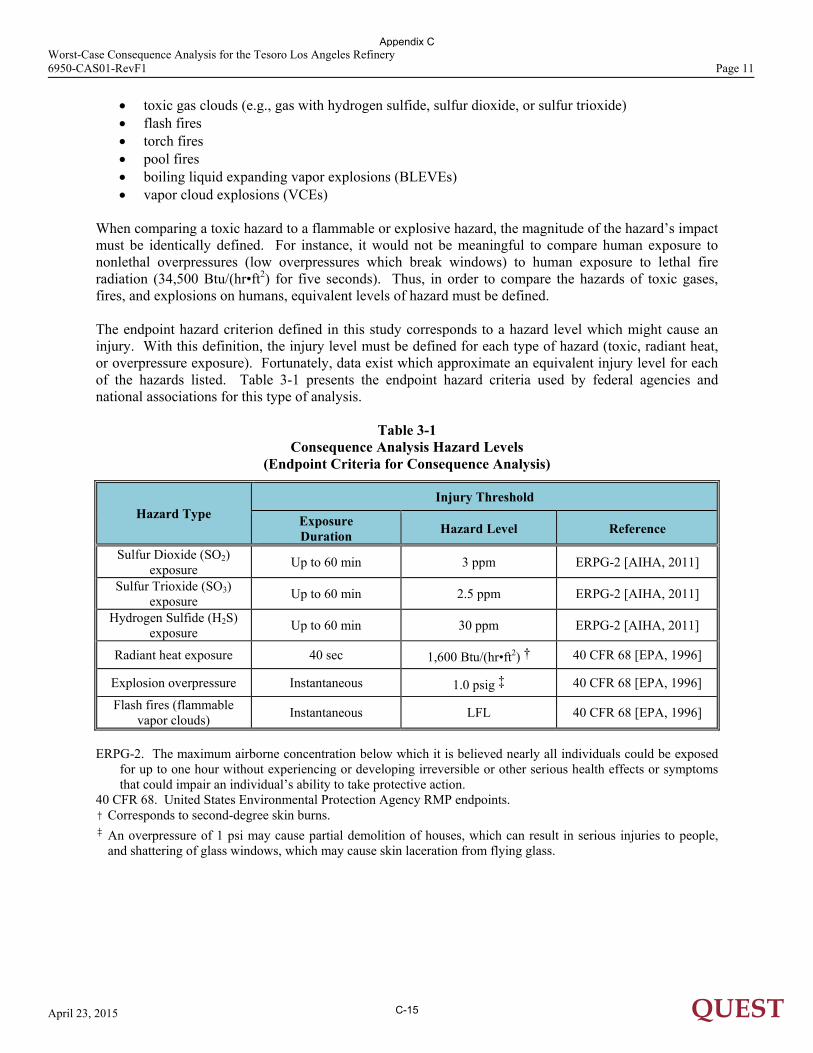
When comparing a toxic hazard to a flammable or explosive hazard, the magnitude of the hazard’s impact must be identically defined. For instance, it would not be meaningful to compare human exposure to nonlethal overpressures (low overpressures which break windows) to human exposure to lethal fire radiation (34,500 Btu/(hr•ft2) for five seconds). Thus, in order to compare the hazards of toxic gases, fires, and explosions on humans, equivalent levels of hazard must be defined. The endpoint hazard criterion defined in this study corresponds to a hazard level which might cause an injury. With this definition, the injury level must be defined for each type of hazard (toxic, radiant heat, or overpressure exposure). Fortunately, data exist which approximate an equivalent injury level for each of the hazards listed. Table 3-1 presents the endpoint hazard criteria used by federal agencies and national associations for this type of analysis.
Table 3-1 Consequence Analysis Hazard Levels
(Endpoint Criteria for Consequence Analysis)
Hazard Type Injury Threshold
Exposure Duration
Hazard Level Reference
Sulfur Dioxide (SO2) exposure
Up to 60 min 3 ppm ERPG-2 [AIHA, 2011]
Sulfur Trioxide (SO3) exposure
Up to 60 min 2.5 ppm ERPG-2 [AIHA, 2011]
Hydrogen Sulfide (H2S) exposure
Up to 60 min 30 ppm ERPG-2 [AIHA, 2011]
Radiant heat exposure 40 sec 1,600 Btu/(hr•ft2) † 40 CFR 68 [EPA, 1996]
Explosion overpressure Instantaneous 1.0 psig ‡ 40 CFR 68 [EPA, 1996]
Flash fires (flammable vapor clouds)
Instantaneous LFL 40 CFR 68 [EPA, 1996]
ERPG-2. The maximum airborne concentration below which it is believed nearly all individuals could be exposed
for up to one hour without experiencing or developing irreversible or other serious health effects or symptoms that could impair an individual’s ability to take protective action.
40 CFR 68. United States Environmental Protection Agency RMP endpoints. † Corresponds to second-degree skin burns. ‡ An overpressure of 1 psi may cause partial demolition of houses, which can result in serious injuries to people,
and shattering of glass windows, which may cause skin laceration from flying glass.
Appendix C
C-15
Worst-Case Consequence Analysis for the Tesoro Los Angeles Refinery 6950-CAS01-RevF1 Page 12
April 23, 2015 QUEST
3.4 Weather Conditions The weather conditions at the time of an accidental release (a LOC event) can influence the extents of the resulting hazards. For the purposes of a consequence-based study, a set of weather conditions – consisting of atmospheric stability and wind speed – must be assigned for each calculation. Atmospheric stability is classified by the letters A through F. In general, the most unstable atmosphere is characterized by stability class A. Stability A would correspond to an atmospheric condition where there is strong solar radiation and moderate winds. This combination of radiation and wind allows for rapid fluctuations in the air and thus greater mixing of the released gas with time. Stability D is characterized by fully overcast or partial cloud cover during both daytime and nighttime. The atmospheric turbulence is not as great during D conditions as during A conditions; thus, the gas will not mix as quickly with the surrounding atmosphere. Stability F corresponds to the most “stable” atmospheric conditions. Stability F generally occurs during the early morning hours before sunrise (thus, no solar radiation) and under low wind. The combination of low wind and lack of solar heating allows for an atmosphere which appears calm or still and thus restricts the ability to actively mix with the released gas. For vapor dispersion calculations, the typical worst-case weather assumption is a stable atmosphere with low wind, which tends to produce longer vapor dispersion distances. The conditions chosen for the dispersion analyses are: Atmospheric Stability Class F Wind Speed 4.5 mph (2.0 m/s) For fire radiation, higher wind speeds generally result in longer impact distances due to flame bending. Atmospheric stability does not affect the size or characteristics of a flame. Thus, a worst-case wind speed for fire radiation was chosen as: Wind Speed 20 mph (8.9 m/s) For all calculations, annual average air temperature and relative humidity values were taken from local meteorological data [weatherspark, 2014]: Air Temperature 65°F (18.3 °C) Relative Humidity 70%
Appendix C
C-16
Worst-Case Consequence Analysis for the Tesoro Los Angeles Refinery 6950-CAS01-RevF1 Page 13
April 23, 2015 QUEST
4.0 IMPLEMENTATION OF WORST-CASE CONSEQUENCE MODELING METHODOLOGY
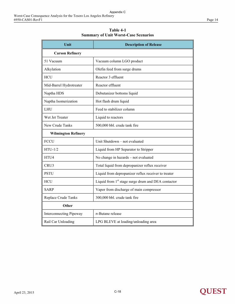
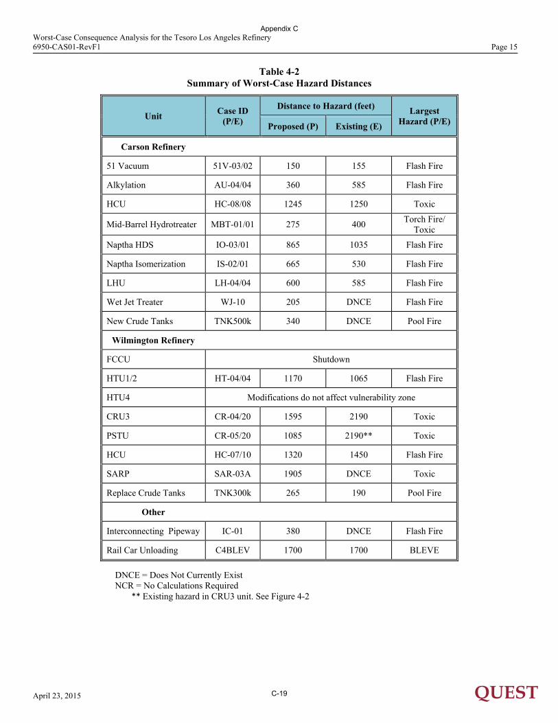
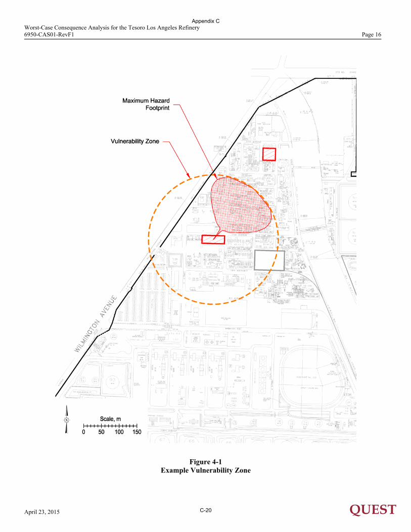
The results of the worst-case consequence modeling calculations for the existing and proposed processes are presented in this section. In addition, for several processes, the vulnerability zone which extends the greatest distance from the point of release is overlaid onto the local area in order to determine possible public exposure to the defined hazard levels. 4.1 Accident Selection The inherent flammable hazards associated with refineries are well known. A review of the Los Angeles Refinery process shows that there are multiple release scenarios that could result in fire or explosion hazards that may generate significant impacts. The hazards from the various release scenarios are identified in the following sections. 4.2 Releases Resulting in the Largest Downwind Hazard Zones When the hazard identification and consequence modeling calculations described in Section 3.0 are completed for the accidents selected in Section 4.1 for both the existing facility and the proposed changes to the facility, the releases which generate the largest hazard zones can be defined for the facility and associated pipeway. Table 4-1 summarizes the worst-case releases identified and Table 4-2 summarizes the maximum hazard zones for each worst-case release. In Table 4-2, P indicates a proposed modification and E indicates an existing unit. 4.3 Worst-Case Consequences 4.3.1 Flash Fires Flash fires are the result of a release, formation of a flammable vapor cloud and ignition of the cloud. Flash fire hazard zones are defined by the maximum extent of the LFL portion of the vapor cloud. For example, a release from the line feeding the Carson light hydrotreater unit (LHU) stabilizer column could result in a flash fire. In this release scenario, the flash fire is the maximum hazard. For the LHU, this scenario is the worst-case scenario because it goes further than the other scenarios chosen for the LHU, so it is used to define the vulnerability zone for the LHU. An example hazard footprint and vulnerability zone associated with this “worst-case” event is illustrated in Figure 4-1. The vulnerability zone (the circle) depicts the potential area that could be affected due to a release from the feed line to the LHU stabilizer column. This presentation is misleading since all locations within this zone cannot be simultaneously exposed to potential flash fire hazard from any single accident. There are other possible hazard zones following this loss of containment that form smaller footprints. The scenario that creates the maximum hazard footprint is just one of the many possible outcomes found when considering variables such as hole size, orientation, wind speed, atmospheric stability, and wind direction. The hazard footprint in Figure 4-1 (the cross hatching) shows what would be expected if the pipe were to rupture, and low speed wind is blowing to the northeast, and the atmosphere is stable, and the release is oriented horizontal, and the gas is ignited after reaching a maximum extent. As shown in Table 4-2, a large fraction of the worst-case release scenarios are flash fires.
Appendix C
C-17
Worst-Case Consequence Analysis for the Tesoro Los Angeles Refinery 6950-CAS01-RevF1 Page 14
April 23, 2015 QUEST
Table 4-1 Summary of Unit Worst-Case Scenarios
Unit Description of Release
Carson Refinery
51 Vacuum Vacuum column LGO product
Alkylation Olefin feed from surge drums
HCU Reactor 3 effluent
Mid-Barrel Hydrotreater Reactor effluent
Naptha HDS Debutanizer bottoms liquid
Naptha Isomerization Hot flash drum liquid
LHU Feed to stabilizer column
Wet Jet Treater Liquid to reactors
New Crude Tanks 500,000 bbl. crude tank fire
Wilmington Refinery
FCCU Unit Shutdown – not evaluated
HTU-1/2 Liquid from HP Separator to Stripper
HTU4 No change in hazards – not evaluated
CRU3 Total liquid from depropanizer reflux receiver
PSTU Liquid from depropanizer reflux receiver to treater
HCU Liquid from 1st stage surge drum and DEA contactor
SARP Vapor from discharge of main compressor
Replace Crude Tanks 300,000 bbl. crude tank fire
Other
Interconnecting Pipeway n-Butane release
Rail Car Unloading LPG BLEVE at loading/unloading area
Appendix C
C-18
Worst-Case Consequence Analysis for the Tesoro Los Angeles Refinery 6950-CAS01-RevF1 Page 15
April 23, 2015 QUEST
Table 4-2 Summary of Worst-Case Hazard Distances
Unit Case ID
(P/E)
Distance to Hazard (feet) Largest Hazard (P/E) Proposed (P) Existing (E)
Carson Refinery
51 Vacuum 51V-03/02 150 155 Flash Fire
Alkylation AU-04/04 360 585 Flash Fire
HCU HC-08/08 1245 1250 Toxic
Mid-Barrel Hydrotreater MBT-01/01 275 400 Torch Fire/
Toxic
Naptha HDS IO-03/01 865 1035 Flash Fire
Naptha Isomerization IS-02/01 665 530 Flash Fire
LHU LH-04/04 600 585 Flash Fire
Wet Jet Treater WJ-10 205 DNCE Flash Fire
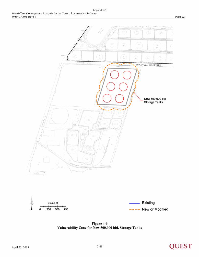
New Crude Tanks TNK500k 340 DNCE Pool Fire
Wilmington Refinery
FCCU Shutdown
HTU1/2 HT-04/04 1170 1065 Flash Fire
HTU4 Modifications do not affect vulnerability zone
CRU3 CR-04/20 1595 2190 Toxic
PSTU CR-05/20 1085 2190** Toxic
HCU HC-07/10 1320 1450 Flash Fire
SARP SAR-03A 1905 DNCE Toxic
Replace Crude Tanks TNK300k 265 190 Pool Fire
Other
Interconnecting Pipeway IC-01 380 DNCE Flash Fire
Rail Car Unloading C4BLEV 1700 1700 BLEVE
DNCE = Does Not Currently Exist NCR = No Calculations Required
** Existing hazard in CRU3 unit. See Figure 4-2
Appendix C
C-19
Worst-Case Consequence Analysis for the Tesoro Los Angeles Refinery 6950-CAS01-RevF1 Page 16
April 23, 2015 QUEST
Figure 4-1
Example Vulnerability Zone
Appendix C
C-20
Worst-Case Consequence Analysis for the Tesoro Los Angeles Refinery 6950-CAS01-RevF1 Page 17
April 23, 2015 QUEST
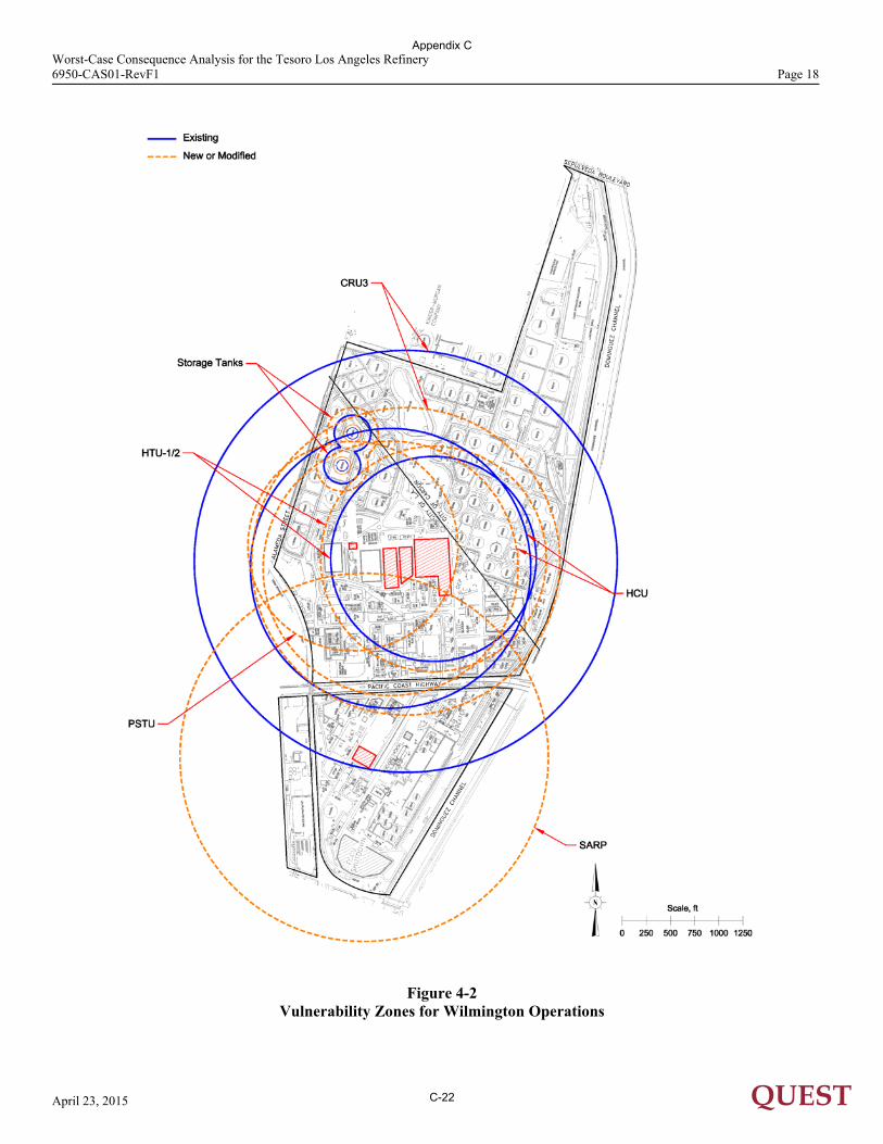
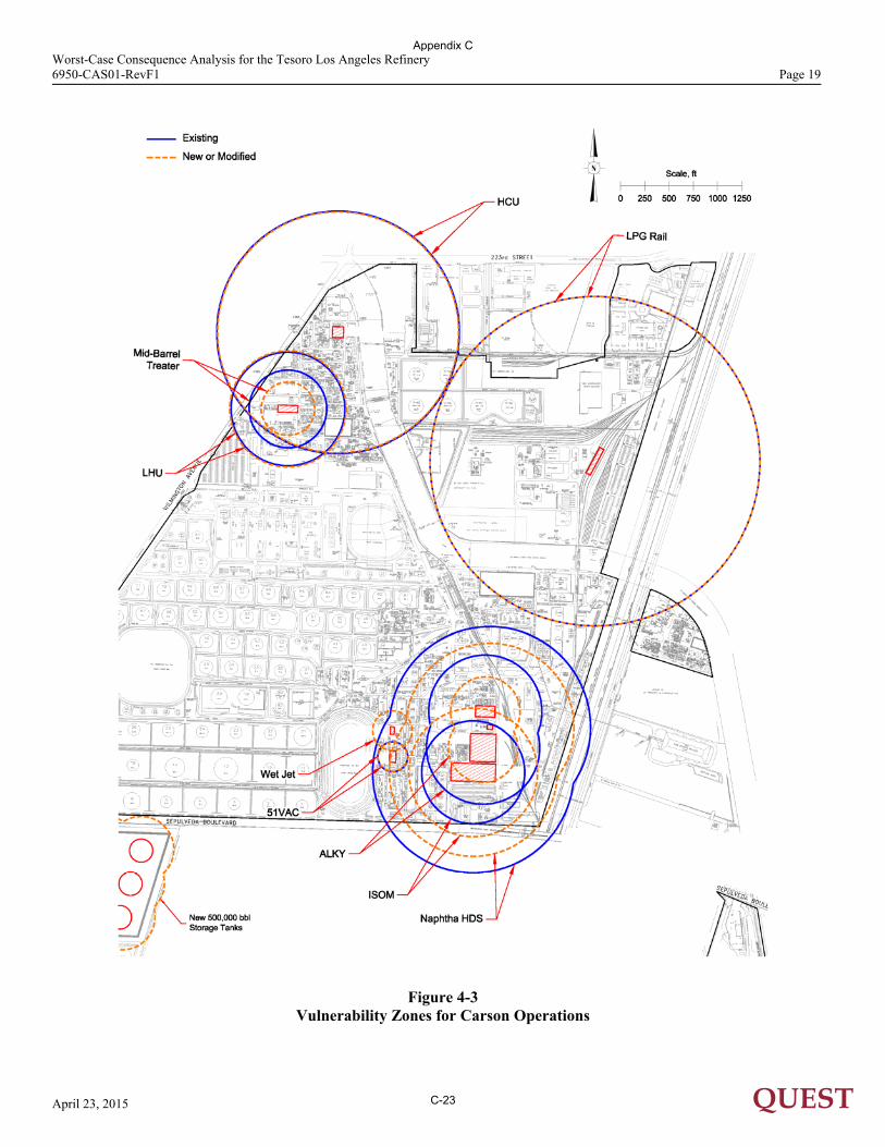
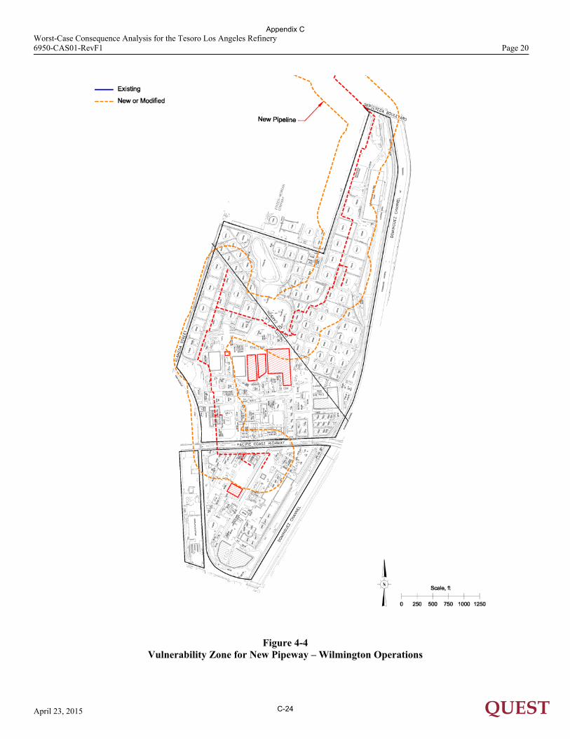
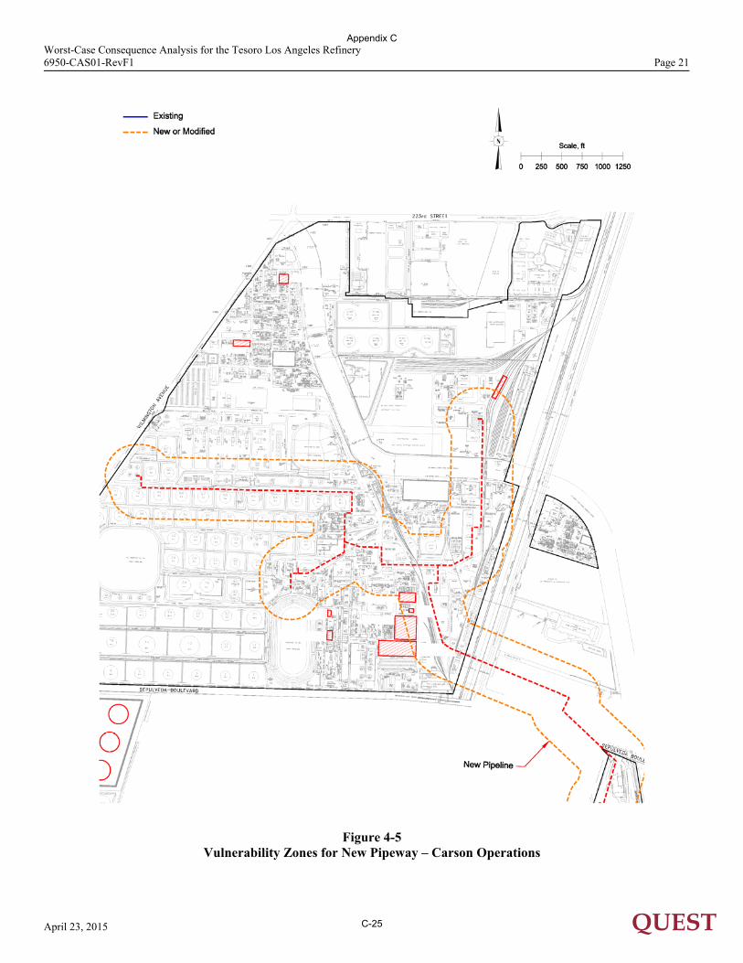
4.3.2 Fire Radiation Fire radiation hazards for this facility are a result of torch fires, pool fires, or BLEVEs. Consequence results for the units where fire radiation is the worst-case scenario are shown in Table 4-2. The largest fire radiation hazard shown in the table is an LPG rail car BLEVE. 4.3.3 Toxic Vapor Clouds H2S, SO2, and SO3 are the only toxic components in any of the processed fluids in the modified areas of the facility. A release of a stream containing H2S, SO2, or SO3 may produce a toxic vapor cloud. The hazard zone of a toxic vapor cloud containing H2S, SO2, or SO3 is defined by the ERPG-2 concentration level (30 ppm H2S, 3 ppm SO2, 2.5 ppm SO3). Releases of material containing H2S produce worst-case vulnerability zones in four areas (Carson HCU and Wilmington CRU3, and PSTU). Releases of material containing SO2 and SO3 produce worst-case vulnerability zones in one unit (Wilmington SARP). The results from the toxic vapor cloud analysis are listed in Table 4-2. 4.3.4 Vapor Cloud Explosions (VCE) One of the possible results of a flammable fluid or gas release is the potential ignition of the vapor which could then result in a VCE. There are no LOC events that could result in VCEs that are not also possible in the existing refinery configuration. No new vulnerability zones are produced by VCE events. 4.4 Summary of Maximum Vulnerability Zones The maximum vulnerability zones for the existing equipment and proposed changes are presented in Figure 4-2 and 4-3 for the Wilmington operation and Figure 4-3 for the Carson operation. Figures 4-4 and 4-5 show the vulnerability zones for the new pipeway in the Wilmington and Carson operation areas. Figure 4-6 shows the vulnerability zone for the new 500,000 bbl. storage tanks. Many of the units have vulnerability zones that are the same size or larger for the existing facility (solid blue lines) than for those that would be produced following the proposed changes (dashed orange lines). New units do not have existing vulnerability zones, so the proposed vulnerability zones would be larger (Carson Wet Jet, Wilmington PSTU and SARP units). The potential hazard zones from releases originating inside the facility at the Carson operation are dominated by the toxic hazards from the HCU and at the Wilmington operation by toxic hazards in the CRU3, PTSU, and SARP areas. The largest potential hazard zone occurring within any modified area is found in the Wilmington SARP area and covers a vulnerability zone with a radius of 1,905 feet.
Appendix C
C-21
Worst-Case Consequence Analysis for the Tesoro Los Angeles Refinery 6950-CAS01-RevF1 Page 18
April 23, 2015 QUEST
Figure 4-2
Vulnerability Zones for Wilmington Operations
Appendix C
C-22
Worst-Case Consequence Analysis for the Tesoro Los Angeles Refinery 6950-CAS01-RevF1 Page 19
April 23, 2015 QUEST
Figure 4-3
Vulnerability Zones for Carson Operations
Appendix C
C-23
Worst-Case Consequence Analysis for the Tesoro Los Angeles Refinery 6950-CAS01-RevF1 Page 20
April 23, 2015 QUEST
Figure 4-4
Vulnerability Zone for New Pipeway – Wilmington Operations
Appendix C
C-24
Worst-Case Consequence Analysis for the Tesoro Los Angeles Refinery 6950-CAS01-RevF1 Page 21
April 23, 2015 QUEST
Figure 4-5
Vulnerability Zones for New Pipeway – Carson Operations
Appendix C
C-25
Worst-Case Consequence Analysis for the Tesoro Los Angeles Refinery 6950-CAS01-RevF1 Page 22
April 23, 2015 QUEST
Figure 4-6
Vulnerability Zone for New 500,000 bbl. Storage Tanks
Appendix C
C-26
Worst-Case Consequence Analysis for the Tesoro Los Angeles Refinery 6950-CAS01-RevF1 Page 23
April 23, 2015 QUEST
5.0 CONCLUSIONS The primary conclusions drawn from the worst-case consequence modeling results are that for most potential releases, the proposed changes result in similar or smaller potential vulnerability zones than those posed by the existing facility configuration. With the maximum vulnerability zones defined for each release evaluated under the existing and proposed refinery configurations, the areas can be divided into three categories, dependent on their potential to impact the public. The categories are defined as:
Areas with no potential off-site impacts for proposed refinery configurations (hazard zones are contained onsite within the facility fence line).
Carson: Alkylation, Wet Jet, 51VAC, MBT Wilmington: HTU-1/2, 80,000 to 300,000 bbl. tank replacement
Areas with potential off-site impacts, but no public residential exposure under proposed refinery
configurations where project modified impacts are similar to or smaller than existing impacts. Carson: HCU, Naptha HDS, LHU, Rail Loading/Unloading Wilmington: PSTU, CRU3, HCU
Areas with potential off-site impacts, but no public residential exposure under proposed refinery
configurations where project modified impacts are larger than existing impacts. Carson: Naptha Isomerization, new 500,000 bbl. Tanks, New Pipeway Wilmington: New Pipeway
Areas with potential public residential exposure.
Carson: none Wilmington: New SARP
These conclusions are driven by the nature of the proposed changes to the Tesoro Los Angeles Refinery. The consequences are determined by the process conditions at the time of release. The proposed changes to the Tesoro Los Angeles Refinery are not expected to significantly change those conditions. Thus, for the purposes of this study, using the hazard endpoints developed by the U.S. EPA and AIHA, the off-site hazard increases associated with the proposed project are limited to adjacent industrial areas near the facility.
Appendix C
C-27
Worst-Case Consequence Analysis for the Tesoro Los Angeles Refinery 6950-CAS01-RevF1 Page 24
April 23, 2015 QUEST
6.0 REFERENCES AIHA, Emergency Response Planning Guidelines threshold values. American Industrial Hygiene
Association, found at http://www.aiha.org/1documents/Committees/ERP-erpglevels.pdf. Baker, Q. A., M. J. Tang, E. Scheier, and G. J. Silva (1994), “Vapor Cloud Explosion Analysis.” 28th
Loss Prevention Symposium, American Institute of Chemical Engineers (AIChE), April 17-21, 1994. Baker, Q. A., C. M. Doolittle, G. A. Fitzgerald, and M. J. Tang (1998), “Recent Developments in the
Baker-Strehlow VCE Analysis Methodology.” Process Safety Progress, Vol. 17, No. 4, Winter, 1998, pp 297-301.
Chang, Joseph C., Mark E. Fernau, Joseph S. Scire, and David G. Strimatis (1998), A Critical Review of
Four Types of Air Quality Models Pertinent to MMS Regulatory and Environmental Assessment Missions. Mineral Management Service, Gulf of Mexico OCS Region, U.S. Department of the Interior, New Orleans, November, 1998.
EPA (1996), Accidental Release Prevention Requirements: Risk Management Programs Under the Clean
Air Act, Section 112(r)(7). Environmental Protection Agency, 40 CFR Part 68, 1996. Hanna, S. R., D. G. Strimaitis, and J. C. Chang (1991), Hazard Response Modeling Uncertainty (A
Quantitative Method), Volume II, Evaluation of Commonly-Used Hazardous Gas Dispersion Models. Study cosponsored by the Air Force Engineering and Services Center, Tyndall Air Force Base, Florida, and the American Petroleum Institute; performed by Sigma Research Corporation, Westford, Massachusetts, September, 1991.
Harris, R. J., and M. J, Wickens (1989), Understanding Vapour Cloud Explosions—An Experimental
Study. The Institution of Gas Engineers, Communication No. 1408, 1989. Hirst, W. J. S., and J. A. Eyre (1982), “Maplin Sands Experiments 1980: Combustion of Large LNG and
Refrigerated Liquid Propane Spills on the Sea.” Proceedings of the Second Symposium on Heavy Gases and Risk Assessment, Frankfurt am Main, May 25-26, 1982: pp. 211-224.
Johnson, D. M., P. Sutton, and M. J. Wickens (1991), “Scaled Experiments to Study Vapour Cloud
Explosions.” IChemE Symposium Series No. 124, Hazards XI, New Directions in Process Safety, Manchester, United Kingdom, April, 1991: pp. 67-85.
Melton, T.A. and J.D. Marx (2009), “Estimating Flame Speeds for Use with the BST Blast Curves.”
Process Safety Progress, Vol. 28, No. 1, March 2009, pp 5-10 Mercx, W.P.M., editor (1994a), Modelling And Experimental Research Into Gas Explosions, Overall final
report of the project MERGE, CEC contract STEP-CT-0111(SSMA), European Commission, Directorate General XII, Brussels, Belgium.
Mercx, W.P.M., A.C. Van den Berg, and Y. Mouilleau (1994b), Modelling And Experimental Research
Into Gas Explosions, Contribution of TNO-PML to the MERGE project, TNO report, PML 1993-C137, Rijswijk, The Netherlands.
Mercx, W.P.M., editor (1997), Extended Modelling And Experimental Research Into Gas Explosions,
Final summary report of the project EMERGE, CEC contract EV5VCT930274, European Commission, Directorate General XII, Brussels, Belgium.
Appendix C
C-28
Worst-Case Consequence Analysis for the Tesoro Los Angeles Refinery 6950-CAS01-RevF1 Page 25
April 23, 2015 QUEST
Mercx, W.P.M., A.C. Van den Berg, and Ph. Van Dongen (1996), Extended Modelling And Experimental
Research Into Gas Explosions, Contribution of TNO-PML to the MERGE project, TNO report, PML 1996-C16, Rijswijk, The Netherlands.
TRC (1991), Evaluation of Dense Gas Simulation Models. Prepared for the U.S. Environmental
Protection Agency by TRC Environmental Consultants, Inc., East Hartford, Connecticut 06108, EPA Contract No. 68-02-4399, May, 1991.
van Wingerden, C. J. M., and J. P. Zeeuwen (1983), “Flame Propagation in the Presence of Repeated
Obstacles: Influence of Gas Reactivity and Degree of Confinement.” Journal of Hazardous Materials, Vol. 8, 1983: pp. 139-156.
Weatherspark (2014) https://weatherspark.com/averages/30723/Long-Beach-California-United-States Wiekema, B. J. (1984), “Vapour Cloud Explosions—An Analysis Based on Accident” (Part I). Journal
of Hazardous Materials, Vol. 8, 1984: pp. 285-311. Wiekema, B. J. (1984), “Vapour Cloud Explosions – An Analysis Based on Accident” (Part II). Journal
of Hazardous Materials, Vol. 8, 1984: pp. 313-329.
Appendix C
C-29
Worst-Case Consequence Analysis for the Tesoro Los Angeles Refinery 6950-CAS01-RevF1 Page A-1
April 23, 2015 QUEST
APPENDIX A
RESUMES
Appendix C
C-30
Worst-Case Consequence Analysis for the Tesoro Los Angeles Refinery 6950-CAS01-RevF1 Page A-2
April 23, 2015 QUEST
John B. Cornwell Quest Consultants Inc.®
Principal Engineer
EDUCATION 1978 M.S., Mechanical Engineering University of Texas, Austin, Texas 1975 B.S., Chemical Engineering University of Texas, Austin, Texas
EXPERIENCE 1989 - Present Quest Consultants Inc., Norman, Oklahoma Principal Engineer Directs the company’s hazards analysis and risk analysis efforts. Directs the use of the
company’s state-of-the-art phenomenological models to determine the extent of potential flammable/toxic/explosive hazards. Presents the technology behind the studies to corporate and regulatory groups.
Directs quantitative risk analysis studies (QRAs) involving:
LNG import and export terminals LPG storage/marketing terminals LPG import terminals Refinery complexes Alkylation units (HF and H2SO4) Ammonia plants Transportation of toxic materials (road and rail) Pipeline networks (natural gas, LPG, ammonia, liquids) Exploration and production systems (oil and natural gas) Gas plants
Directs development of computer software, CANARY by Quest®, that provides analysis tools for the company. Oversees the use of public domain (e.g. DEGADIS, SLAB, LNGFIRE3) and special application software.
1985 - 1989 Energy Analysts, Inc., Norman, Oklahoma Principal Engineer Directed the development of computer models to simulate the hazards associated with
accidental releases of toxic/flammable materials. These models were contained in a commercially available software package named EAHAP.
Appendix C
C-31
Worst-Case Consequence Analysis for the Tesoro Los Angeles Refinery 6950-CAS01-RevF1 Page A-3
April 23, 2015 QUEST
John B. Cornwell
Modeled the simulation of heavier-than-air gases and momentum jet releases of gases and aerosols. Directed the comparison analysis of several heavier-than-air gas dispersion models against the large-scale test data produced by the Thorney Island Trials, Desert Tortoise Ammonia Releases, and the Goldfish Hydrofluoric Acid Releases.
Directed numerous risk analysis/assessment studies using results of the consequence
modeling and in-house risk modeling capabilities. Prepared and reviewed California RMPPs (Risk Management and Prevention Plans).
1984 - 1985 Los Alamos National Laboratory, Los Alamos, New Mexico Staff Member/Research Scientist, Advanced Technologies Division Security Clearance Level Q (DoE) Evaluated advanced energy systems, including advanced fusion devices, liquid
oxygen/liquid hydrogen turbogenerators, advanced photovoltaic systems, and conventional petroleum-based turbine systems.
1981 - 1984 Energy Analysts, Inc., Norman, Oklahoma Senior Engineer
Directed the development of advanced simulation models for the dispersion of heavier-than-air vapors. Developed compatible thermodynamic systems and methodologies for predicting transient vaporization history of cryogenic fluids.
Directed development of a risk analysis model for use in conjunction with results of vapor dispersion and fire radiation analyses. The risk analysis model was employed in studies requiring the time-varying/site-dependent risk profile for petrochemical facilities and the surrounding area.
Evaluated transient fire hazards and the analysis of toxic combustion products. 1978 - 1981 University of Texas, Austin, Texas Research Scientist, Center for Energy Studies Developed a series of mathematical models to evaluate geopressured/geothermal
resources along the Texas gulf coast.
PROFESSIONAL MEMBERSHIPS American Institute of Chemical Engineers Air and Waste Management Association American Nuclear Society
Appendix C
C-32
Worst-Case Consequence Analysis for the Tesoro Los Angeles Refinery 6950-CAS01-RevF1 Page A-4
April 23, 2015 QUEST
John B. Cornwell
PUBLICATIONS Authored papers on hazards analysis modeling, risk analysis methodologies, project siting issues, and model-to-test data analysis.
RELEVANT PROJECT EXPERIENCE Quantitative Risk Analysis for an LNG Import Terminal: Project Manager for a full QRA of an LNG import terminal on Mexico’s gulf coast. QRA was submitted to Mexico’s Department of the Environment (SEMARNAT). Other studies completed under this contract included a qualitative risk analysis and siting study per Mexico’s Secretary of Energy, Energy Regulation Commission (CRE). Terminal is now under construction. Client: Shell Global Solutions. Quantitative Risk Analysis of a Refrigerated LPG Import Terminal: Project Manager for a study that included refrigerated LPG ship loading/unloading and cavern storage. Full QRA was completed and submitted for review to Chinese authorities. Client: Caltex Corporation (now part of ChevronTexaco). LNG Facility Siting Safety Study for a Pacific Ocean Gravity Based Structure (GBS) for Use as an Import Terminal: Participant in a study to determine if a proposed LNG import terminal could be built upon a GBS in the Mexican waters off Baja California. The study applied Mexico’s NOM-EM-001-SECRE-2002 to the design. The project involved vapor dispersion, fire radiation, and vapor cloud explosion modeling for numerous hypothetical releases of LNG. Client: ChevronTexaco Quantitative Risk Analysis for an Existing HF Alkylation Unit: Project Manager for a full QRA of an existing HF alkylation unit. QRA was used to develop potential mitigation options. Client: Sunoco Quantitative Risk Analysis for Natural Gas Transmission Pipeline: Project Manager for a full QRA of a natural gas transmission line spanning the Gulf of Mexico from Alabama to Florida. Torch fire and flash fire radiation hazards were defined. QRA was submitted to US FERC as part of project permitting. Client: Willbros Engineers, Inc. Quantitative Risk Analysis of a Refrigerated and Pressurized LPG Storage Depot: Project Manager for a full QRA of a LPG storage depot and a nearby chemical facility. Analysis of terrorist threat included. Facility had been target of failed domestic terrorism in 1999. Client: City of Elk Grove, California. Quantitative Risk Analysis for Natural Gas Gathering Pipeline Network: Project Manager for a full QRA of a natural gas gathering network in Venezuela. Wellhead, compression and pipeline releases were evaluated. Toxic (Hydrogen Sulfide) and fire radiation hazards were defined. QRA was submitted to Petroleos de Venezuela (PDVSA) for review and approved per PDVSA standard IR-S-02. Client: Petroleos de Venezuela. Quantitative Risk Analysis for an Existing HF Alkylation Unit: Project Manager two full QRAs of an existing HF alkylation unit were conducted to identify the possible risk benefit afforded by the use of acid additive. Client: Texaco
Appendix C
C-33
Worst-Case Consequence Analysis for the Tesoro Los Angeles Refinery 6950-CAS01-RevF1 Page A-5
April 23, 2015 QUEST
John B. Cornwell
Quantitative Risk Analysis for an LNG Import Terminal: Project Manager for a full QRA of an LNG import terminal on Mexico’s Pacific coast. QRA was submitted to Mexico’s Department of the Environment (SEMARNAT). Other studies completed under this contract included a qualitative risk analysis and siting study per Mexico’s Secretary of Energy (CRE). Client: Sempra Energy. LNG Carrier Spill Hazards Analysis: Project Manager for an analysis of possible large scale LNG carrier releases in Boston Harbor. Results used by U.S. Department of Energy in designing LNG tanker operations in Boston Harbor following September 11, 2001 terrorist attacks. Client: U.S. Department of Energy. Comparative Quantitative Risk Analysis for an HF Alkylation Unit Upgrade: Project Manager for a comparative (before and after) set of QRAs of an existing HF alkylation unit. The QRAs were used to demonstrate the benefits associated with three mitigation measures (individually or in concert); rapid dump system, water curtains, and water cannons. Client: Ampol LNG Facility Siting Safety Study for Gulf of Mexico Gravity Based Structure (GBS) for Use as an Import Terminal: Participant in a study to determine if the proposed LNG import terminal could be built upon a GBS in the Gulf of Mexico. The study included meshing the import terminal design with applicable LNG standards. This involved vapor dispersion, fire radiation, and vapor cloud explosion modeling for numerous hypothetical releases of LNG. Client: ChevronTexaco Consequence Analysis Course: Instructor for an introductory course covering the principals of consequence analysis. Course covers accidental releases and the methods to predict the extent of potential fire, explosion and toxic hazards. Course is provided through the Mary Kay O’Conner Process Safety Center located at Texas A&M University. Client: Texas A&M University, College Station, Texas Quantitative Risk Analysis for an LNG Import Terminal: Project Manager for a full QRA of an LNG import terminal on Mexico’s Pacific coast. QRA was submitted to Mexico’s Department of the Environment (SEMARNAT). Other studies completed under this contract included a qualitative risk analysis and siting study per Mexico’s Secretary of Energy (CRE). Client: ConocoPhillips. Quantitative Risk Analysis for Natural Gas Gathering Pipeline Network: Project Manager for a full QRA of a natural gas gathering network. Wellhead and pipeline releases were evaluated. Toxic (Hydrogen Sulfide) and fire radiation hazards were defined. QRA was submitted to US EPA’s technical staff for review and approved. Client: Union Pacific Resources. Quantitative Risk Analysis for an HF Alkylation Unit Addition to Existing Refinery: Project Manager for a full QRA of a new HF alkylation unit to be added to an existing refinery. QRA was submitted to local and Federal Israeli authorities. Evaluation included acid additive as well as water spray mitigation systems. Client: Paz Ashdod Refinery Limited. Quantitative Risk Analysis for a Proposed Gas-to-Liquids Facility: Project Manager for a full QRA of a new gas-to-liquids facility along the Nigerian coast. QRA was submitted to local and Federal Nigerian authorities. Client: Chevron Energy and Technology
Appendix C
C-34
Worst-Case Consequence Analysis for the Tesoro Los Angeles Refinery 6950-CAS01-RevF1 Page A-6
April 23, 2015 QUEST
David W. Johnson Quest Consultants Inc.®
Principal Engineer
EDUCATION 1969 Ph.D., Chemical Engineering University of Oklahoma, Norman, Oklahoma 1965 B.S., Chemical Engineering University of Texas, Austin, Texas
EXPERIENCE 1989 - Present Quest Consultants Inc., Norman, Oklahoma
Principal Engineer
Facilitated HAZOP, SIL/LOPA, What If?, HAZID, and HEMP (bowtie) reviews for numerous projects, including:
Chemical complex Oil and gas processing facilities Refinery units LNG baseload (export) facilities LNG import facilities Offshore oil and gas processing
Performed consequence modeling for siting and safety studies of several liquefied natural gas (LNG) facilities. Involved in numerous consequence analysis, risk analysis, and facility siting studies involving refineries, gas plants, pipelines, and petrochemical plants.
Responsible for Quest’s testing and research programs, and for the development and implementation of analytical models for predicting accidental release rates, aerosol formation, pool spreading, heat transfer, and vaporization rates.
Directed all major aspects of several experimental programs involving releases of hazard-ous fluids.
On-site tests conducted to determine if the flammable cloud produced by
emergency venting of ullage gas from a crude oil pipeline surge tank could reach associated process areas.
Two field-test programs conducted to evaluate the efficacy of additives designed to reduce the amount of aerosol formed during accidental releases from HF alkylation units.
Release tests conducted for the Petroleum Environmental Research Foundation (PERF) to determine the potential for a hydrocarbon/sulfuric acid emulsion to form an aerosol upon its release.
Appendix C
C-35
Worst-Case Consequence Analysis for the Tesoro Los Angeles Refinery 6950-CAS01-RevF1 Page A-7
April 23, 2015 QUEST
David W. Johnson
Aerosol release tests conducted for the CCPS at the DOE Nevada Test Site.
Assisted in development of RMPPs for several refinery units in California, including alkylation, hydrotreating, hydrocracking, catalytic cracking, delayed coking, and product storage. This work included a review of unit HAZOPs, selection of potential release scenarios, estimation of accident frequencies, and supervision of hazard modeling.
1983 - 1989 Energy Analysts, Inc., Norman, Oklahoma
Principal Engineer
Conducted HAZOP study for a proposed refinery expansion in the Philippines. Trained refinery personnel as HAZOP leaders for future HAZOP studies.
Responsible for the technical content of the final safety analysis report (FSAR) for the Big Hill Strategic Petroleum Reserve (SPR) site. Tasks completed included identification and analysis of hazards; review of site layout and design; and equipment, piping, and instrumentation evaluation. Made recommendations to improve site operations.
Developed risk models in the areas of fire and thermal radiation, rate of fluid release from containment, and Gaussian dispersion for EAHAP hazards analysis computer code.
Designed and participated in several large-scale outdoor fire and fluid release tests designed to determine the burning and release characteristics of hydrocarbon fluids.
1977 - 1983 Applied Technology Corporation, Norman, Oklahoma
Vice President Developed mathematical models in the areas of fire radiation, vapor dispersion, and heat transfer. Applied these models to LNG facility safety studies. Designed and conducted several large-scale outdoor tests involving fire and materials combustion. Tests included the burning and subsequent extinguishment of hexane, LPG, and carbon disulfide pool fires.
1970 - 1977 University Engineers, Inc., Norman, Oklahoma
Senior Engineer Project manager of a semi-works seawater desalination project utilizing direct contact heat transfer and freezing to produce potable water. Involved in several large-scale outdoor fire tests to study the flammability characteristics of thermal insulation products.
1965 Celanese Fibers Corporation, Rock Hill, South Carolina
Development Engineer Adapted existing plant equipment for new and more productive uses, developed computer models describing machine operations, and assisted in plant start-up.
Appendix C
C-36
Worst-Case Consequence Analysis for the Tesoro Los Angeles Refinery 6950-CAS01-RevF1 Page A-8
April 23, 2015 QUEST
David W. Johnson
PROFESSIONAL MEMBERSHIPS
National Society of Professional Engineers American Institute of Chemical Engineers Oklahoma Society of Professional Engineers
PUBLICATIONS Authored more than twenty-five papers in the areas of physical properties, kinetics, and process plant safety.
RELEVANT PROJECT EXPERIENCE Process Hazards Analysis (PHA) of a Large LNG Liquefaction Facility: Directed the HAZOP and LOPA studies for a large scale grass roots LNG facility in Texas. Studies for both the FEED and EPC were performed as well as Management of Change (MOC) reviews. Client: Sabine Pass LNG. Process Hazards Analysis (PHA) of a Large LNG Liquefaction Facility: Directed the HAZOP and LOPA studies for a large scale grass roots LNG facility in Australia. Studies for both the FEED and EPC were performed as well as Management of Change (MOC) reviews. Client: Gladstone LNG. Process Hazards Analysis (PHA) of Multiple Nitrogen Rejection (NRU) and Cryogenic Processing Units: Directed the HAZOP and MOC studies for multiple nitrogen rejection and cryogenic units in Texas, New Mexico, and Wyoming. Client: BCCK Engineering. Process Hazards Analysis (PHA) of a Refinery Crude Unit: Directed the HAZOP for a refinery crude unit. Client: Caltex Corporation (now part of ChevronTexaco). Development of an Improved Hydrogen Fluoride Alkylation Catalyst: Project Manager for a research project involving the large scale outdoor release of anhydrous hydrogen fluoride (HF) and hydrogen fluoride mixed with vapor pressure reducing additives. The purpose of the testing was to validate lab scale results with respect to the reduction of aerosol formation of the released HF. Client: Mobil Research and Development Corporation (now a part of Exxon/Mobil). Development of an Improved Hydrogen Fluoride Alkylation Catalyst: Project Manager for a research project involving the large scale outdoor release of anhydrous hydrogen fluoride (HF) and hydrogen fluoride mixed with vapor pressure reducing additives. The purpose of the testing was to validate lab scale results with respect to the reduction of aerosol formation of the released HF. Client: Texaco Inc.(now a part of ChevronTexaco).
Appendix C
C-37