Embed Size (px)
Citation preview

APPENDIX A UNOLS Rope and Cable Safe Working Load Standards
A.0 DEFINITIONSA.0.1 WINCH OWNER: The party or their representative who is normally responsible
for the operation, inspection, maintenance, and testing of the winch. This could be the vessel operator or the scientific party.
A.0.2 ROPE: A woven, flexible tension member with no internal conductors. It may be made from natural fibers, synthetic fibers, or metal.
A.0.3 CABLE: A woven, flexible tension member with internal conductors or other means of transmitting data such as glass fiber.
A.0.4 TENSION MEMBER: Generic name used to describe a rope or cable in service for over the side work.
A.0.5 ELASTIC LIMIT: The elastic limit or yield point of a material is the stress at which a material begins to deform plastically. Prior to the yield point the material will deform elastically and will return to its original shape when the applied stress is removed. Once the yield point is passed some fraction of the deformation will be permanent and non-reversible. For rope or cable this is the load that causes permanent set, or deformation, of the strandswires. (See Background Information)
A.0.6 TRANSIENT LOADS: Loads induced which are temporary by nature, including the weight of entrained mud, weight of entrained water, pull out loads, drag due to package characteristics and/or winch speed, etc.
A.0.7 DYNAMIC LOADS: Loads induced due to vessel motion (heave, roll, pitch, etc.)
A.0.8 “g” = The vertical acceleration due to gravity. For normal static loading (no dynamic effect), “g” is equal to 1.0. To take into account dynamic effect due to ship’s motion and package drag, the simple static load is multiplied by a factor higher than 1.0. Under ABS standards, normally 1.75 or 2.0 for vertical accelerations is used depending on the application. “g” is applied to the mass of the package and tension member, not the weight.
A.0.9 “D” = The root diameter of the sheave.
A.0.10 “d” = The outside diameter of the cable or rope.
A.0.11 "d1" = For cable the largest diameter wire in the armor wires. For wire rope the largest of the outer wires.
A.0.12 “w” = The width of the sheave groove supporting the sides of the wire or cabletension member.
A.0.13 ULTIMATE LOAD (UL): The theoretical load that produces failure. For the purposes of this standard, the “Ultimate Load” is assumed to be either the

Nominal Breaking Load (NBL) or the Assigned Breaking Load (ABL) as defined below.
A.0.14 NOMINAL BREAKING LOAD (NBL): Manufacturer’s minimum published breaking load for a rope or cable.
A.0.165 FIXED ENDS (FE) Both ends of the tension member being fixed without the ability to swivel. Most wire rope and cable NBL values are based on FE. An example of a fixed end application is towing a MOCNESS.
A.0.165 FREE TO ROTATE The end of the tension member is free to rotate either because a swivel is at the end of the tension member or the package at the end of the cable tension member can rotate freely. Wires and CablesTension members used in free to rotate applications typicaly have a NBL below the fixed end NBL. An example of a free to rotate application is a lowered CTD package.
A.0.176 INDUCED ROTATION Induced rotation occurs when external forces cause torque to be applied to the tension member. An example of an induced rotation situation would be a tow vehicle that spins while being towed but a swivel is not in place to decouple the vehicle from the tension member. This situation could develop if the tail fin of a corer was bent. Induced rotation should never be allowed to occur on a tension member that has not been specifically designed for this purpose.
A.0.187 TESTED BREAKING LOAD (TBL): The actual load required to pull a tension member to destruction as determined by testing. Depending on the intended use of the tension member testing may need to be done under fixed end and free to rotate conditions.
A.0.198 ASSIGNED BREAKING LOAD (ABL): Will be the lowest of the Ultimate Load, Nominal Breaking Load and Tested Breaking Load. In practice ABL will be equal to NBL used unless testing shows TBL to be less than NBL. A value greater than the NBL may never be used. Depending on the intended use of the tension member there may be two ABLs for fixed end and free to rotate conditions.
A.0.1920 SAFE WORKING LOAD (SWL): The maximum tension that is allowed to be applied to the tension member during normal operation.
A.0.210 FACTOR OF SAFETY (FS): For the purpose of this document defined as Assigned Breaking Load / Safe Working Load.
A.0.2120 SWL = ABL / FS For the purposes of this standard, FS shall be considered the value selected by the operator. Because there may be two different ABLs (fixed end & free to rotate) there may be two SWLs. Section 6.0 defines the minimum standards that must be met to select specific FS values.
A.0.2231 Auto-Render: The capability of the winch to automatically pay out at a pre-set maximum tension in order to prevent the tension member from exceeding the pre-set tension.

A.0.2432 Render/Recover: A means of a winch to automatically maintain a pre-set tension by alternately paying-out and hauling back. Generally recovery haul back is limited to the point of the initial rendering.
A.1 REFERENCESA.1.1 HANDBOOK OF OCEANOGRAPHIC WINCH, WIRE AND CABLE
TECHNOLOGY, Third Edition.
A.1.2 Mechanics of Materials, Second Edition, Gere and Timoshenko, 1984
A.1.3 Wires and Cables Deployed Overside of RVS Vessel – Generic Operating Limits, Document Number SE301050, Issue No.: 001, 12/01/00.
A.2 GENERALA.2.1 46 CFR 189.35 – “Weight Handling Gear” describes design standards for
handling systems aboard inspected oceanographic research vessels. However, this standard does not address FS on the cables and/or wire ropetension members. The purpose of this appendix to the RVSS is to establish safe and effective operating limits for vessels in the UNOLS fleet for cables and ropestension members loaded beyond traditional shore-side limits.
A.2.2 This standard seeks to define the requirements, which must be adhered to during over-the-side deployments in order to maintain a safe working environment for all personnel aboard. The secondary goal of this standard is to minimize damage to cables tension members and handling equipment, and the loss of scientific equipment, while still permitting the science objective to be met.
A.2.3 Normal operation beyond the parameters defined in this standard is forbidden. Exceptions to this are an emergency situation declared by the Master or other officer in charge of the vessel.
A.2.4 Loading limitations are expressed in terms of Factor of Safety (FS) on Assigned Breaking Load (ABL) in this document.
A.2.5 The limits in this document may not be used where other regulations are applicable, for example, on cargo cranes. In such cases, the shore-side regulations, which apply, must be adhered to. For example, the Occupational Safety and Health Administration (OSHA) generally requiresrequire a 5.0 FS on cable breaking strength.
A.2.6 This standard assumes that the rope or cabletension member is properly used for its intended purpose.
A.2.7 This standard will be met as soon as the appropriate equipment can be funded and purchased and no later than 18 months after the published date of this revision of the RVSS
A.3 INSPECTION, TESTING AND PREVENTATIVE REQUIREMENTSA.3.1 Cable paths and fairlead arrangements vary widely from ship to ship and
change over both the short term (from cruise to cruise) and the life of the

vessel. It is impossible to develop a set of standards, which tries to quantify the precise effects on breaking strength, or cable tension member life, as a result of system design. Instead, each vessel must have a testing program in place, which suits how their cables and ropestension members are used, and routinely evaluates the status of each. The assumption is that the results of testing will indicate the effect of both the loading and system design on the breaking strength of the rope or cabletension member.
A.3.2 The testing program followed shall be based on the FS selected by the Owner, which is in turn based on use and the particulars of the handling system employed. The Owner shall have documentation in place specifying the FS for each rope or cabletension member in use.
A.3.3 Cable Tension member test samples shall be a clean, “representative” length from the end that will be put into future use, not simply the end immediately adjacent to the existing termination. Although this may not be the location of maximum loading during operations, this represents a practical means of determining ABL from an operational standpoint.
A.3.4 The initial ABL shall be assigned through testing by the UNOLS Wire Pool before distribution to the fleet. If the initial test results in an ABL less than the NBL, the Wire Pool shall reject the rope or cabletension member.
A.3.5 If subsequent testing results in a TBL that is greater than or equal to the initial ABL, the initial ABL shall be used by the Vessel Operation for the purposes of this standard.
A.3.6 If subsequent testing results in a TBL that is less than the initial ABL, then the new TBL shall be used in lieu of the initial ABL by the Vessel Operation for the purposes of this standard.
A.3.7 Method of determining (TBL) – Steel Wires and Cables: ASTM A931-96, “Standard Test Method for Tension Testing of Wire Rope and Strand” (Re-approved 2002) shall be used. Tests shall be done with one end of the tension member free to rotate.
A.3.8 The Vessel Operator shall send samples to a UNOLS-accepted test facility (WHOI Wire Pool as of October November 20092010) for consistency of testing purposes and maintaining statistics. For steel cables and wire rope, the Operation shall send a five-meter (16 ft) test sample (as described in Section 4.3) terminated on both ends with the fittings normally used in the field. If the field terminations are found to not develop full breaking strength, a test may be conducted using standard poured epoxy resin terminations.
A.3.9 The Vessel Operator shall also provide a copy of the wire history or wire log information with the sample and, as a minimum, this should include the following:
UNOLS wire identifier, as described in Chapter 7 UNOLS Winch and Wire Handbook, Third Edition
Winch and system manufacturer. Number and/or duration of deployments since last test.

Maximum tension of each deployment. Maximum payout of each deployment. Description of wire train: the number of sheaves between winch and water.
Sheave material and values of “D” and “w” for each sheave.
A.3.10 A hard copy and/or electronic copy of the TBL test results and ABL will be provided to the Vessel Operator for each sample tested
A.3.11 Method of determining (TBL) – Synthetic Ropes and Cables: [RESERVED]
A.3.12 Electromagnetic Testing: [RESERVED]
A.3.13 DC Resistance Testing: [RESERVED]
A.3.14Retirement – Steel Wires Ropes and Cables: Beside obvious physical damage (kinks, bird caging, abrasion, broken strands, excessive corrosion, etc.), a length of cable tension member shall be removed from service, or cut back so that the unacceptable length is removed, if any of the three following criteria are met:
If the ABL, with the appropriate FS applied as described above, does not meet future scientific requirements.
If the ABL deteriorates below 50% of NBL. Peak tension over turning sheaves at any time during operations exceeds
the Elastic Limit.
A.3.15 Retirement – Synthetic Ropes and Cables: [RESERVED]
A.3.16 Lubrication: As long as these testing and inspection programs are adhered to, lubrication of steel ropes and cablestension members is not expressly required. However, if an operation determines that it is cost effective, and does not affect the quality of the science data collected, lubrication is highly encouraged since it generally extends servicecable life.
A.3.17 Fresh Water Wash Down: While understanding that fresh water is limited at sea, an automatic system that washes the rope or cabletension member on retrieval is highly encouraged since it greatly extends servicecable life.
A.4 BACKGROUND INFORMATIONA.4.1 Performance Over a Rolling Sheave: When a steel wire rope or cable passes
over a rolling sheave, up to a 30% reduction in breaking strength can occur (Ref 1.1 Section 6.4, Pg 8-22). For a wire tension member with a nominal breaking load of 10,000 lbs, this would be a reduction in strength of 3,000 lbs. Using a FS of 1.5 on in this example cable, the Safe Working Load equals 6,667 lbs – or a reduction of 3,333 lbs – just above the reduction in strength anticipated. Since all oceanographic cables tension members pass over at least one sheave, this is the primary argument for not exceeding a FS of 1.5.
A.4.2 Yield Point and Elastic Limit: “Yield Point” is where continued deformation will occur without adding significantly more load. The “Elastic Limit” is considered to be the load, which induces permanent set or deformation. For steel, the “Yield Point” and “Elastic Limit” are essentially the same for all practical purposes. However, these two points may be quite different for other materials such as synthetics and glass fiber. Since wire rope and cables are made of

strands and are not solid bars of steel, the precise Yield Point can be hard to determine by testing. A point on the stress-strain curve known as “0.2% Offset Yield” is used instead. The 0.2% Offset Yield for three-strand wire rope can be found in Section 2.2 (pg 1-5) of Reference 1.
A.4.3 For cables with copper conductors, the yield point generally occurs anywhere from 50-55% of the breaking strength (FS = 1.8) at which point the performance of conductors deteriorates. This is the principle argument for not exceeding a FS of 2.0 for steel cables with copper conductors, the goal being to maintain conductor performance over the life of the cable.
A.4.4 For wire rope, the yield point generally occurs around 75% of the breaking strength (FS = 1.33). This is the other reason for not exceeding a FS of 1.5 on steel wire rope, the goal being to maintain the useful life of the wire rope. This limit matches well with the performance over rolling sheaves above.
A.4.5 When using low FS in oceanographic research, the capabilities of the wire tension member monitoring system become critical with respect to capturing and displaying dynamic loads. This standard is divided into three primary sections (Tables 6.1 – 6.4) because of this; with each section having increasingly stringent requirements for the monitoring system. If the monitoring system is not capable of reliably capturing peak (or low) dynamic loads, then the chosen FS must keep the wire or cabletension member below its yield point.
A.4.6 For example, on a wire with a breaking strength of 20,000 lbs, the approximate yield point would be 20,000 x 0.75 = 15,000 lbs. Using a FS of 2.5, the allowable loading would be 20,000/2.5 = 8,000. If the system is not capable of reliably capturing dynamic effect, then a worst case scenario of 1.75 times static load would have to be assumed (i.e. “g” = 1.75), or 8,000 x 1.75 = 14,000. 14,000 is below the approximate yield strength of 15,000 so the integrity of the cable tension member would be preserved despite the monitoring system. The graph below illustrates this, and is why a FS of 2.5 is used as the lower limit in Table 6.2

A.4.7 When a tension measuring system is not available which forces using a minimal FS of 5.0, estimates of tension due to “dynamic loading” must be done based on mass not weight. In general, the weight of the package, entrained water and the cable or rope in air is roughly equal to the mass. Do not use weight in water for the dynamic loading estimates.
A.5 WINCHES AND HANDLING SYSTEM DESIGNA.5.1 All handling systems and winches, whether portable or permanently installed,
must be properly designed to an appropriate standard as described in Appendix B of the RVSS.
A.5.2 A calibrated weak link or “Auto-render” may be used by the vessel to ensure the chosen wire FS that best meets operational demand is maintained.
A.5.3 For operations where the weak link itself might be entangled or buried, then Auto-Render shall be the preferred method of strain relief.
A.5.4 Depending on the particular handling system and the type of vessel per Appendix B, when the NBL is at or below the Safe Working Load (SWL) of all components in the handling system, a weak link or Auto-Render may be set to the desired FS that best meets operational demand per Tables 6.1 – 6.4. (See Example 7.4)
A.5.5 Depending on the particular handling system and the type of vessel per Appendix B, when the ABL is higher than the SWL of any component in the handling system then the weak link or Auto-Render may be set equal to or below the SWL of the weakest component. (See Example 7.5)
A.6 REQUIREMENTS

The Tables (6.1 – 6.45) on the following pages outline the procedures for operating at different ranges of Factor of Safety (FS).


Table 6.1 Wire Rope or Cable Factor of Safety 5.0 or GreaterTable 6.1 - Wire Rope or Cable - Factor of Safety 5.0 or greater
General Wire Rope or Cable of steel construction may be operated to a nominal FS = 5.0 on the ABL, including transient and dynamic loads, as long as the following precautions in this section are adhered to.When the minimum Factor of Safety of 5.0 is reached, the deployment must be halted, or the next level of standards described in Table 6.2 must be used.Sea conditions and the resulting ship motion will affect the transient loads created on the wire. Thus, the trend in prevailing weather should be assessed before committing to a deployment, which could approach the limits specified above.
Tension Monitoring
Tension may be determined by calculation of instrument weight, wire, weight and entrained volume of water, including transient and dynamic loads, as long as the Owner is confident that a FS of 5.0 will not be compromised. If no other precise information is available on package drag and/or vessel accelerations, the Vessel Operator should use the ABS “g” factor of 1.75 as a minimum.
Alarms None
Sheaves The sheave diameter should be at least equal to or greater than the manufacturer’s recommendations.
Deck Safety Personnel on deck should follow good safety practices when working in the vicinity of wires and ropes during use
Testing No routine break testing is required. Wires shall only be tested every two years to the desired SWL, along with the handling system.
Logbooks
At a minimum, the Owner shall maintain logs showing cutbacks, spooling operations, lubrication, wire train description and maximum loading (as determined by monitoring system or by calculation for each cast) for the full service life of the rope or wire. The wire log shall transfer with the wire if it is removed and placed in storage, or transferred to another winch or Owner.
Winch Operator
The Owner and the Master of the vessel must deem competent, in writing, all winch operators. “Deemed Competent” means that both the Owner and the Captain are confident, given the particulars of the winch and the overall operational scenario (weather conditions, equipment being deployed, etc.), that the Winch Operator has the necessary experience to operate the winch safely.

Table 6.2 Wire Rope or Cable Factor of Safety From Less Than 5.0 to 2.5
Table 6.2 - Wire Rope or Cable - Factor of Safety From Less Than 5.0 to 2.5
General Wire rope or cable of steel construction may be operated to a nominal FS =2.5 on the ABL, including transient and dynamic loads, as long as the following precautions in this section are adhered to.When the minimum Factor of Safety of 2.5 is reached, the deployment must be halted, or the next level of standards described in Table 6.3 must be used.Sea conditions and the resulting ship motion will affect the transient loads created on the wire. Thus, the trend in prevailing weather should be assessed before committing to a deployment, which could approach the limits specified above.Motion-compensation may be used to reduce the dynamic loads below the permissible limit and/or to reduce the chances of a “zero load” condition.
Tension Monitoring
Tension must be monitored at the winch operator’s station with a display resolution of at least 3 Hz (every 330 mS). The system must also be capable of logging tension data at a minimum frequency of 3 Hz (every 330 mS). The tension measuring system must be calibrated at a minimum of every 6 months at load equal to the imposed at a FS of 2.5. The tension measuring system must be maintained with an accuracy of 4% of the applied load.
AlarmsThe handling system shall be fitted with both audible and visual tension alarms that sound and/or illuminate prior to reaching of 40% (FS = 2.4FS=2.7) of abased on the wire’stension member’s Assigned Actual Breaking Load (ABL). Alarm conditions must automatically be included in the logged data.
Sheaves & Rollers
The sheave and roller diameter(s) throughout must should be equal to or greater than the larger of either: the manufacturer’s recommendation; 40 x d; or 400 x d1 (use the largest). Grooving of the sheaves should be as close to “d” as practical, and generally no larger than 1.5d
Deck SafetyThe Operator should identify “Danger Zones” around ropes and wires under tension. To the extent possible, given the nature of operations involved, all personnel should be excluded from these zones such that a sudden failure cannot result in injury.
Testing
Wire Samples from the end closest to the termination shall be sent for testing every two (2) years and generally in conjunction with handling system SWL tests. If a 10% decrease in ABL is detected, then the testing shall be increased to annually. Alternately, the Owner may cut back to and re-test a new representative length
Logbooks
At a minimum, the Owner shall maintain logs showing cutbacks, spooling operations, lubrication, wire train description and maximum loading (as determined by monitoring system or by calculation for each cast) for the full service life of the rope or wire. The wire log shall transfer with the wire if it is removed and placed in storage, or transferred to another winch or Owner.
Winch Operator
The Winch Owner must certify that all Winch Operators are competent. By “Certified Competent” it is meant that the Owner must have written documentation in place showing that the operator has been through and successfully passed a formal owner/operator developed training program on the winch, handling apparatus, and monitoring system. The system vendor or the Owner, depending on the complexity of the system, may conduct a formal training program. The certification must be renewed annually. The master shall verify qualifications and designate the approved winch operators.


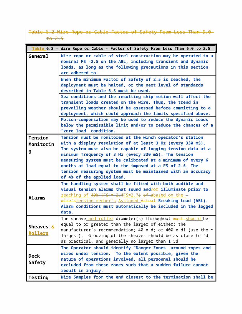
Table 6.3 Wire Rope or Cable Factor of Safety From Less Than 2.5 to 2.0Table 6.3 - Wire Rope or Cable - Factor of Safety From Less Than 2.5 to 2.0
General Wire rope or cable of steel construction may be operated to a nominal FS =2.0 on the ABL, including transient and dynamic loads, as long as the following precautions in this section are adhered to.FOR CABLES -When the minimum Factor of Safety of 2.0 is reached, the deployment must be halted. FOR WIRE ROPE -When the minimum Factor of Safety of 2.0 is reached, the deployment must be halted, or the next level of standards described in Table 6.4 must be used.Sea conditions and the resulting ship motion will affect the transient loads created on the wire. Thus, the trend in prevailing weather should be assessed before committing to a deployment, which could approach the limits specified above.Motion-compensation may be used to reduce the dynamic loads below the permissible limit and/or to reduce the chances of a “zero load” condition.
Tension Monitoring
Tension must be monitored at the winch operator’s station with a display resolution of at least 10 Hz (every 100 mS). The system must also be capable of logging tension data at a minimum frequency of 20 Hz (every 50 mS). Tension must be continuously monitored using a “tension trending” graph at the winch operator’s station. The tension measuring system must be calibrated at a minimum of every 6 months at load equal to the imposed load at a FS of 2.0. The tension measuring system must be maintained with an accuracy of 3% of the applied load.
Alarms
The handling system shall be fitted with both audible and visual tension alarms that sound and/or illuminate prior to reaching of FS=2.2 based on the tension member’sprior to 45% (FS = 2.2) of a wire’s Actual BreakingAssigned Breaking Load (ABL). Alarm conditions must automatically be included in the logged data.
Sheaves & Rollers
The sheave and roller diameter(s) throughout should be equal to or greater than the larger of either: the manufacturer’s recommendation; 40 x d; or 400 x d1 (use the largest). Sheave grooving should be per Ref A.1.1, Chapter 1, and Section 11.0 to provide adequate support.
Deck Safety
The Operator should identify “Danger Zones” around ropes and wires under tension. To the extent possible, given the nature of operations involved, all personnel shall be excluded from these zones such that a sudden failure cannot result in injury. Warning notices should be displayed at points of access indicating the danger. Physical and/or visual barriers should be erected as needed. Existing doors and accesses to the area should be secured when possible
Testing
Wire Samples from the end closest to the termination shall be sent for testing annually. If a 10% decrease in ABL is detected, then the testing shall be increased to every six months. Alternately, the Owner may cut back to and re-test a new representative length.
Logbooks
At a minimum, the Owner shall maintain logs showing cutbacks, spooling operations, lubrication, wire train description and maximum loading (as determined by monitoring system for each cast) for the full service life of the rope or wire. The wire log shall transfer with the wire if it is removed and placed in storage, or transferred to another winch or Owner.
Winch Operator The Winch Owner must certify that all Winch Operators are competent. By “Certified Competent” it is meant that the Owner must have written documentation in place showing that the operator has been through and successfully passed a formal owner/operator developed training program on the winch, handling apparatus, and monitoring system. The system vendor or the

Owner, depending on the complexity of the system, may conduct a formal training program. The certification must be renewed annually. The master shall verify qualifications and designate the approved winch operators.

Table 6.4 Wire Rope Factor of Safety From Less Than 2.0 to 1.5Table 6.4 - Wire Rope - Factor of Safety From Less Than 2.0 to 1.5
General Wire rope of steel construction may be operated to a nominal FS =1.5 on the ABL, including transient and dynamic loads, as long as the following precautions in this section are adhered to.Once a FS = 2.0 is reached a regular check on wire loading shall be performed. This will require halting a deployment at regular intervals (~ 500 m) and conducting a slow haul until the nominal and peak tensions are established and verified. A decision on whether to proceed must then be based upon the limiting value of SF = 1.5. The deployment must be halted, when the minimum Factor of Safety of 1.5 is reached.Sea conditions and the resulting ship motion will affect the transient loads created on the wire. Thus, the trend in prevailing weather should be assessed before committing to a deployment, which could approach the limits specified above.Motion-compensation may be used to reduce the dynamic loads below the permissible limit and/or to reduce the chances of a “zero load” condition.
Tension Monitoring
Tension must be monitored at the winch operator’s station with a display resolution of at least 10 Hz (every 100 mS). The system must also be capable of logging tension data at a minimum frequency of 20 Hz (every 50 mS). Tension must be continuously monitored using a “tension trending” graph at the winch operator’s station. The tension measuring system must be calibrated at a minimum of every 6 months at load equal to the imposed load at a FS of 1.5. The tension measuring system must be maintained with an accuracy of 3% of the applied load.
AlarmsThe handling system shall be fitted with both audible and visual tension alarms that sound and/or illuminate prior to reaching a FS=1.7 based on the tension member’s prior to reaching 60% (FS = 1.7) of a wire’s Actual Assigned Breaking Load (ABL). Alarm conditions must automatically be included in the logged data.
Sheaves & Rollers
The sheave and roller diameter(s) throughout should be equal to or greater than the larger of either: the manufacturer’s recommendation; 40 x d; or 400 x d1 (use the largest). Sheave grooving should be per Ref A.1.1, Chapter 1, and Section 11.0 to provide adequate support.
Deck Safety
The Operator should identify “Danger Zones” around ropes and wires under tension. To the extent possible, given the nature of operations involved, all personnel shall be excluded from these zones such that a sudden failure cannot result in injury. Warning notices should be displayed at points of access indicating the danger. Physical and/or visual barriers should be erected as needed. Existing doors and accesses to the area should be secured when possible
TestingWire Samples from the end closest to the termination shall be sent for testing annually. If a 10% decrease in ABL is detected, then the testing shall be increased to every six months. Alternately, the Owner may cut back to and re-test a new representative length.
Logbooks
At a minimum, the Owner shall maintain logs showing cutbacks, spooling operations, lubrication, wire train description and maximum loading (as determined by monitoring system or by calculation for each cast) for the full service life of the rope or wire. The wire log shall transfer with the wire if it is removed and placed in storage, or transferred to another winch or Owner.
Winch Operator
The Winch Owner must certify that all Winch Operators are competent. By “Certified Competent” it is meant that the Owner must have written documentation in place showing that the operator has been through and

successfully passed a formal owner/operator developed training program on the winch, handling apparatus, and monitoring system. The system vendor or the Owner, depending on the complexity of the system, may conduct a formal training program. The certification must be renewed annually. The master shall verify qualifications and designate the approved winch operators.

6.1 Synthetic Tension Members [Reserved]

6.21 Ship operators and their seagoing staff must understand that if, by force of circumstance or by their wish to maintain scientific operations while on a cruise, they they continue to operatedo not meeting operating requirements as described in tables 6.1 through 6.4, they are embarking on a potentially dangerous activity. The consequences of this activity could be loss of valuable equipment, damage to the vessel and its fixed equipment, and, in the worst case, injury to personnel.

Table 6.5 Synthetic Tension Members [Reserved]

A.7 EXAMPLESA.7.1 Examples of where a SF of 5 has to be used because a tension measuring
system is not available.
A grab is planned on 500m of 0.25” 3x19 wire rope using a FS of 5.0.Assigned Breaking Load (Free to Rotate) = 6750 lbs./FS 5.0SWL = 6750 / 5.0 1350
Pound-mass of Grab 200Pound-mass of Entrained Mud (in air) 50Pound-mass of 500m of wire rope (in air) = 0.327 lbs./m x 500 m 164Static Total 414Dynamic effect 414 x g (g=1.75) 724Pull Out Load = 100 pounds force 100Estimated Maximum Load Pounds-force 824Because the estimated maximum load of 824 pounds is less than the SWL of 1,350 pounds it is acceptable to proceed with this grab.
----------------------------------------------------
A CTD cast is planned on 500m of 0.322 cable rope using FS of 5.0.Assigned Breaking Load (Free to Rotate) 10,000FS 5.0SWL = 10,000 / 5.0 2000
Pound-mass of CTD 800Pound-mass of Samples (24 btls x 10 liters sea water =240 liters, 240 x 2.2lb/l) 528Pound-mass of 500m of wire rope/cable (in air) = 0.327 lbs./m x 500 m 287Static Total 1615
Dynamic effect 1,615 x g (g estimated at 1.75) 2826Estimated Maximum Load Pounds-force 2826Because the estimated maximum load of 2,826 pounds is more than the SWL of 2,000 pounds it is NOT acceptable to proceed with this CTD cast.Vessel Operator must either: know the actual dynamic loading on the package (based on location on vessel, drag, weather conditions, etc.) and/or meet the requirements allowing a lower FS described in Section 6 in order to proceed.All of the components in the wire handling system (Winch, blocks & a-frame) are required to have a UL rating in excess of the UL of the tension member.

A.7.2 Example: Estimating the FS Requirements that will need to be met.
A piston core is planned on 4000 m of 9/16” wire rope with an ABL of 32,000 lbs. The winch and frame are both rated for 50,000 lbs.Pound-mass of Corer 1,500Pound-mass of 4000 m of wire rope (in air) = 1,614/m x 4,000 m 6,455Pound-mass of entrained mud (estimated) 500Static Total 8,455
Dynamic effect (multiply static load by g = 1.75) 14,796Pull out Load – Pounds-force 3,000Estimated Maximum Load Pounds-force 17,796F.S = ABL divided by the estimated Maximum Load = 32,000/17,796 1.8In order to proceed with this core the requirements in Section 6 for operating at a safety factor (FS) of 1.5 will need to be met.Since there is a “substantial risk” of entanglement with this kind of operation, a weak link should be selected by the Vessel Operator to protect the rope.
A.7.3 Example: Calculating the amount of dynamic loading that can occur before an operation needs to be halted for when the minimum FS of 2 is reached.
A 36-bottle CLIVAR CTD cast deploying 6000 meters of .322-diameter cable is planned. The steel cable has a Free to Rotate ABL of 10,000 lbs. The SWL of the handling system is 10,000 lbs. The minimum FS permitted for E.M. cables is 2.0 per Section 6; therefore the maximum tension allowed on the cable is 5,000 lbs.The Vessel Operator has chosen to use a FS of 2.0 on the cable under Section 6 above. The Vessel Operator must either know either the actual dynamic loading on the package (based on location on vessel, drag, etc.) and/or monitor cable tensions closely as required in Section 6.3, or use motion compensation to reduce dynamic effect.
Weight of CTD (weight in water estimated) 900Weight of entrained water in bottles (weight in water) 0Weight of Cable (weight in water) 2,834Static Weight of System in water (FS = 2.7 if no Dynamic Loading) 3,734
Pound Mass of CTD (weight in air of 36 bottle CTD with weights and LADCP) 1,493Mass of entrained water (12 out of 36 – 10 liter bottles @ 2.3 lb./l) 276Mass of Cable (weight of 0.322 cable in air = 0.574 lb./m) 3,444Mass of System 5,213
Dynamic Load in heavy weather – g = 1.75 (Mass x g) 9,123Factor of Safety is unacceptable 1.10
Dynamic Load in FLAT calm weather – g = 1.1 (Mass x g) 5,734Factor of Safety is just beyond acceptable for the cable’s conductors 1.74

6,000-meter deployments with a 36-bottle rosette on 0.322 cable easily falls below a FS of 2.0 and can only be accomplished in very calm weather or with motion compensation.Note: It is clear that deep CTD operations using 0.322 cable in heavy weather or with a large/heavy CTD will easily exceed an FS of 2.0 and could go lower than 1.5. This is below the advisable limit for conductor cable because of the increased potential failure of the internal conductors. If FS is reduced to this level, decreased cable life due to failure of internal conductors should be anticipated. Operators should do everything possible to reduce ship or deployment system movement. Operators can use a motion compensation package or slow down the rate of winch operation in order to reduce the dynamic load until the length of deployed cable is reduced below about 3,500 meters with just half the bottles filled to keep loads at 5,000 lbs. or lower. As an alternative, a stronger cable could be considered, however most stronger UNOLS Cables also weigh more – see next example
----------------------------------------------------
A CLIVAR CTD cast deploying 6000 meters of 0.680-diameter coax cable is planned. The steel cable has a Free to Rotate ABL of 37,000 lbs. The SWL of the handling system is 45,000 lbs. The minimum FS permitted for E.M. cables is 2.0 per Section 6; therefore the maximum tension allowed on the cable is 18,500 lbs.The Vessel Operator has chosen to use a FS of 2.0 on the cable under Section 6 above. The Vessel Operator must either know the actual dynamic loading on the package (based on location on vessel, drag, etc.) and/or monitor cable tensions closely as required in Section 5.0, or use motion compensation to reduce dynamic effect.
Weight of CTD (weight in water) 900Weight of entrained water in bottles (weight in water) 0Weight of Cable (weight in water) 10,883Static Weight of System in water (FS = 3.1 if no Dynamic Loading) 11,783
Pound Mass of CTD (weight in air of 36 bottle CTD with weights and LADCP) 1,493Mass of entrained water (12 out of 36 – 10 liter bottles @ 2.3 lb/l) 276Mass of Cable (weight of 0.680 cable in air = 2.273 lb/m) 13,368Mass of System 15,407
Dynamic Load in heavy weather – g = 1.75 (Mass x g) 26,963Factor of Safety is unacceptable 1.4
Dynamic Load in FLAT calm weather – g = 1.1 (Mass x g) 16,948Factor of Safety is just beyond acceptable for the cable’s conductors 2.2
6,000 meter deployments with a 36-bottle rosette on 0.680 cable gives a slightly better FS than 0.322 for deep casts. An even greater FS can be achieved with 0.681 F.O. cable that has a breaking strength of around 46,000 and is only slightly heavier than 0.680. A 36 place CTD with all bottles full can be handled at a FS of 2.0 in conditions that yield a “g” factor as high as 1.4 resulting in estimated dynamic loads as high as 23,444.Note: In all circumstances, a full ocean depth CTD cast will require using the procedures contained in Table 6.3 for FS between 2.0 and 2.5 as long as a steel cable is being used

due to the weight and mass of the deployed cable. The level of tension monitoring will allow the operator to use actual dynamic loading to make decisions about whether or not to continue a cast.

A.7.4 Example: A cable with a NBL of 20,000 lbs. is used in conjunction with Section 6.2 on a handling system rated for 20,000 lbs. The weak link (or winch slip) would be set to 20,000/2.5 = 8,000 lbs. Maintaining the 3.0 FS on the cable becomes the controlling factor.
A.7.5 Example: A cable with an NBL of 20,000 lbs. is used on a winch having a SWL of 10,000 lbs. The weak link (or winch slip) shall be set at or below 10,000 lbs. Protecting the winch becomes the controlling factor. FS on the cable in this case is 2.0 and Section 6.3 applies if this level of loading is reached.
If the deck-bolting pattern can only support a cable tension of 5,000 lbs given handling system geometries, then the Auto-Render shall be set at or below 5,000 lbs. Keeping the winch bolted to the deck becomes the controlling factor. FS on the cable in this case is 4.0 and Section 6.2 applies if this level of loading is reached.