Embed Size (px)
Citation preview

Appendix A: Microprocessor Data Sheets
Intel8085 Zilog Z80 MOS Technology 6502 Motorola 6809 Microcontrollers (Single-chip Microcomputers) Intel 8086 ( & 80186 & 80286) Zilog Z8000 Motorola 68000 32-bit Microprocessors lnmos Transputer
184

Appendix A 185
Intel 8085
Followed on from the 8080, which was a two-chip equivalent of the 8085. Not used in any home computers, but was extremely popular in early (late 1970s) industrial control systems.
Start addresses of Interrupt Service Routines:
RESET-()()()(J TRAP- 0024
RST5.5- 002C RST6.5 - ()(J34 RST7.5- <XJ3C
A15-A8
AD7-ADO
ALE
Multiplexed d
B
D
H
ata bus and lower half of
address bus (require 8212 to split data and address buses)
P/Os
SP
PC
A
c E
L
Flags
Same register set is used in 8080
8155- 3 ports, 256 bytes RAM 8255 - 3 ports 8355 - 2 ports, 2K ROM 8755 - 2 ports, 2K EPROM
INTR - from interrupting device
Other 8251- USART support 8253- CTC (3 counters) devices: 8271 - FDC
Intel DMA Control System
CPU busesde-multiplexed
8202 - Dynamic RAM controller 8257 - DMA controller 8257 - CRT controller
Character
Video signal to CRT

186 Microcomputer Fault-finding and Design
Zilog Z80
Probably the most popular 8-bit microprocessor. Used in home computers (Spectrum, Amstrad, Tandy), office computers and industrial controllers.
8 data lines
(to refresh dynamic RAMI
/SR (Interrupt Service Routine) start addresses
RESET-0000 NMI- 0066
A F A' F'
B c B' C'
D E D' E'
H L H' L'
Interrupt Memory vector I refresh R
Index register IX
Index register IY
Stack pointer
Based on the Intel 8085, but possesses second set of registers.
INT- CPU obeys contents of Interrupt Vector for CPU 'mode 0' - 0038 for CPU 'mode 1' - XXYY for CPU 'mode 2' (XX is contents of Interrupt Vector
YY is supplied on Data Bus from interrupting device) 'Vector' (CPU examines XXYY to find start address of ISR)
ZBO P/0
ZBO PIO
Port A
4 addresses: 00- Port A (data) 01- Port A (control) 10- Port B (data) 11 -Port B (control)
Send OF to Control register for output port, 4F for input port.
ZBO CTC
External pulses
Address
Data
"' CLK/TRO CLK/TRT
CLK/TR2 CLK/TRJ
ZC/TOO
ZC/TOT
ZC/T02
I Zero count, or Timeout
4 channels (counters). Each possesses its own control register - same address as counter.

Zilog ZSO
ZBO DART
Duai-UART (Z80 SIO
Address
is almost Data identical, but offers additional synchronous transmission)
zso DART
Appendix A 187
TxA } RxA TxCA Channel A
RxCA Modem control
----- signals (DTR,
-TxB } RxB TxCB RxCB
DSR, RTS, CTS) also
Channel B
ZBO 'Daisy-chain' Interrupt System
I !NT
PIO
lEI lEO
1 (+5 vd 1 1 I Daisy-chain
I !NT
CTC
lEI lEO
Common (shared) mterrupt line
~ lEI;
f !NT
DART
lEI lEO
-!NT
CPU
Interrupt enable in
lEO; Interrupt enable out
I 1 0 l I o oL ~ Daisy-chain broken (CTC is
interrupt active). so DART cannot generate an interrupt

188 Microcomputer Fault-finding and Design
MOS Technology 6502
Very popular 8-bit microprocessor used in home computers, such as BBC, Apple 2, Acorn Atom, Commodore PET and VIC 20.
Memory Map
0000
16 address lines
8 data lines I
Other members of the family possess only 28 pins, such as 6503 - 12 address lines 6504- 13 address lines
PCH I PCL
Accumulator A
Index register X
Index register Y
Program counter PC
Stack pointer SP
Status register
OOFF 0100
Zero page (256 bytes)
Page 0 - Can be used as registers within instructions (memory, so slow transfers)
Stack Page 1 (must
01FF 0200
(256 bytes) beRAMI P/0
FFFA FFFB FFFC FFFD FFFE FFFF
User area
LSB
MSB
} NMI vector
} RESET vector
} IRQ vector
No input/output instructions (like 6809), so memory mapped input/output must be used.
P/0/Memory
6530- 2 ports, 1 counter, IK ROM, 64 bytes RAM
Possesses 2 ports, 2 counters
UART
Data
50 baud to 19200 baud
TxD} RxD Data
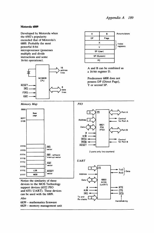
Motorola 6809
Developed by Motorola when the 6502's popularity exceeded that of Motorola's 6800. Probably the most powerful 8-bit microprocessor (possesses multiply and divide instructions and some 16-bit operations).
MC6809 CPU
Memory Map
0000 .....------,
Base page
OOFF 0100 1------1
FFFB
FFF9
FFFA
FFFB
FFFC
FFFD
FFFE LSB
FFFF MSB
}IRQ vector
} SWI- software interrupt vector
} NMI vector
} RESET vector
Notice the similarity of these devices to the MOS Technology support devices (6522 PIO and 6551 UART). These devices can be used with the 6809. Also 6839 - mathematics firmware 6829 - memory management unit
8 data lines
P/0
UART
Address
Data
Tx and Rx clocks
Appendix A 189
A I B Accumulators
DP I Flags
X
y }
Index registers
SP (User)
SP (System)
PC
A and B can be combined as a 16-bit register D.
Predecessor 6800 does not possess DP (Direct Page), Y or second SP.
2 ports only (no counters)
6850 A CIA
(UART)
TxD} RxD Data
RTS CTS DCD
1 Handshaking

190 Microcomputer Fault-finding and Design
Motorola 6809
Application- VDU Design
Address bus
J J 128 8K RAM 6809 1K Address
CPU ROM bytes Data (display RAM r buffer)
r r Data bus
...._ Character Shift Video
Address generator f- register f--. to
- ROM CRT
J j_ J UART Keyboard CRT
6850 encoder controller
I r r 6845
ASCII characters received from remote computer (through UART) are loaded into 8K RAM (display buffer). CRT controller removes these bytes and uses Character generator ROM to generate row for the dot matrix for each character.

Appendix A 191
Microcontrollers (Single-chip Microcomputers)
These devices employ 8-bit CPUs, but include some memory and input/ output. This single-chip solution often produces a smaller and cheaper assembly for such applications as:
(a) washing machine controller; (b) telephone answering machine.
The instruction set is not normally easy to use, and instructions are 1 or 2 bytes long. Typical pin functions:
Port 1
Port 2
Port 3
Intel Microcontrollers
Sometimes the address and data bus lines are multiplexed with the port lines to allow external devices to be connected.
The most commonly used members of the Intel family are:
(1) 8048- 3 ports, 1 counter, 64 bytes RAM, 1K ROM (2) 8748- 3 ports, 1 counter, 64 bytes RAM, 1K EPROM (3) 8035- 3 ports, 1 counter, 64 bytes RAM (no ROM) (4) 8049- 3 ports, 1 counter, 128 bytes RAM, 2K ROM (5) 8022- 3 ports, 1 counter, 64 bytes RAM, 1K ROM, 1 ADC (6) 8051- 3 ports, 1 counter, 128 bytes RAM, 4K ROM, 1 UART plus
extra instructions (for example, multiply and divide)
Zilog Microcontrollers
(1) Z8601- 4 ports, 2 counters, 1 UART, 144 bytes RAM, 2K ROM (2) Z8602- 4 ports, 2 counters, 1 UART, memory buses (3) Z8603- 4 ports, 2 counters, 1 UART, 144 bytes RAM, 2K ROM,
2K EPROM ('piggy-backed' on top of device) (4) Z8681- 4 ports, 2 counters, 1 UART, memory buses (5) Z8611, Z8612 and Z8613- 4K versions of (1), (2) and (3) (6) Z8671- as (1) with BASIC interpreter
192 Microcomputer Fault-finding and Design
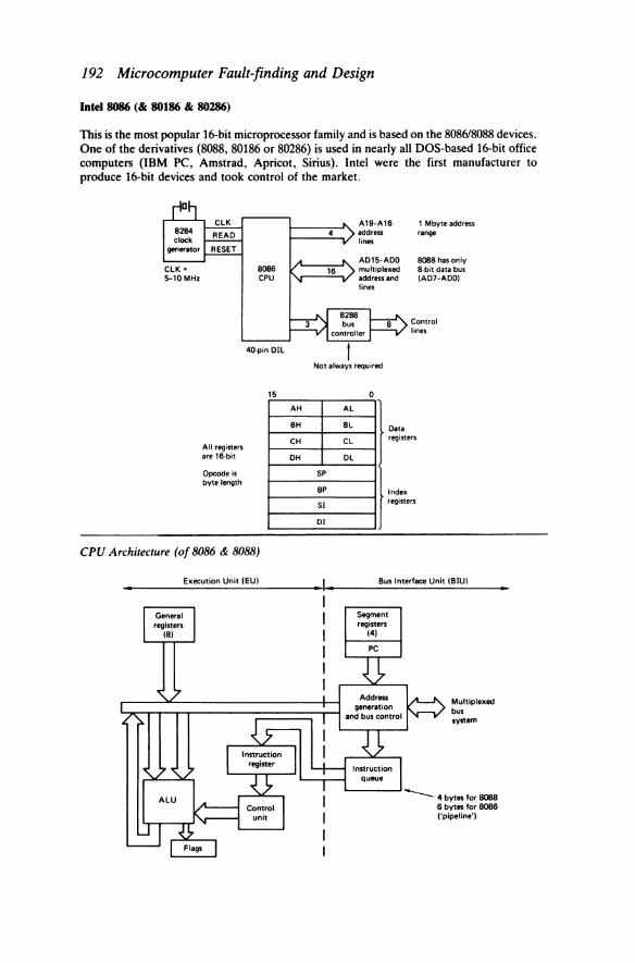
Intel 8086 (& 80186 & 80286)
This is the most popular 16-bit microprocessor family and is based on the 8086/8088 devices. One of the derivatives (8088, 80186 or 80286) is used in nearly all DOS-based 16-bit office computers (IBM PC, Amstrad, Apricot, Sirius). Intel were the first manufacturer to produce 16-bit devices and took control of the market.
CLK= 5-10 MHZ
All registers are 16-bit
Opcode is byte length
8066 CPU
40·pin OIL
15
CPU Architecture (of 8086 & 8088)
Execution Unit lEU I
A19-A16
1---..:::4~/ ~i~:ess 1 Mbyte address range
AH AL
BH BL
CH CL
DH DL
SP
BP
Sl
01
0
8088 has only 8-bit data bus lA07-ADOI
Control lines
}-registers
}'-registers
Bus Interface Unit lBIUI
Segment registen
141
Multiplexed bus system
-- 4 bytes for 8088 6 bytes for 8088 ("pipeline")

Appendix A 193
Intel 8086 (& 80186 & 80286)
Instructions arc pre-fetched from memory and placed in Instruction Queue (or ·pipeline') to increase program execution speeds. The segment registers allow program (code). data and stack to occupy different MK memory segments.
Memon· Segmentation
Memory
_f Code (64K)
Segment registers
Code segment ICS) Data
Data segment IDS) (64K)
Stack segment ISS)
L Extra segment (ES) Stack
As each address (64K)
leaves the CPU, it is modified by the contents of one of the segment registers
Application of8086 (Apricot Computer)
ALE
Example 1
JsoooJ Code segment (CS) Add
J4000J PC
Result J64000J Physical address to memory
Example 2
Add
Rosult
J3000J Data segment I OS)
J6789J Offset I 16-bit)
J36789J Physical address to memory
A19-A16 To/from 16K EPROM 512K RAM
A 15-AO ldynamicl
015-DO
UART FDC etc.
I. The XOX7 performs floating point arithmetic ( + high precision fixed point arithmetic. mathematical functions. such as SINE).
2. The XOXY handles 1/0 transfers (such as DMA transfers to/from floppy or hard disk).
194 Microcomputer Fault-finding and Design
Intel 8086 (& 80186 & 80286)
80186
As 8086, plus the following on-chip functions: 1. Clock generator 2. Chip select logic (7 1/0, 6 memory) 3. Timers (3) 4. DMA control (2 channels) 5. Programmable interrupt controller.
Mounted in a 64-pin JEDEC 'chip carrier'.
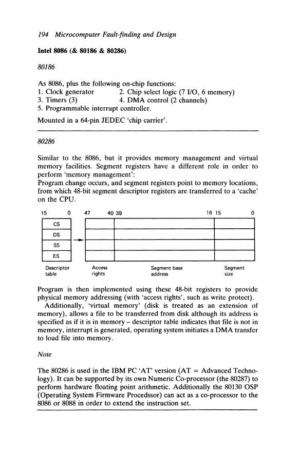
80286
Similar to the 8086, but it provides memory management and virtual memory facilities. Segment registers have a different role in order to perform 'memory management': Program change occurs, and segment registers point to memory locations, from which 48-bit segment descriptor registers are transferred to a 'cache' on the CPU.
15 0 47 40 39 16 15 0
cs OS
~----~~~----~------------------------~--------~ ss ES
Descriptor table
Access rights
Segment base address
Segment size
Program is then implemented using these 48-bit registers to provide physical memory addressing (with 'access rights', such as write protect).
Additionally, 'virtual memory' (disk is treated as an extension of memory), allows a file to be transferred from disk although its address is specified as if it is in memory - descriptor table indicates that file is not in memory, interrupt is generated, operating system initiates a DMA transfer to load file into memory.
Note
The 80286 is used in the IBM PC 'AT' version (AT= Advanced Technology). It can be supported by its own Numeric Co-processor (the 80287) to perform hardware floating point arithmetic. Additionally the 80130 OSP (Operating System Firmware Procedssor) can act as a co-processor to the 8086 or 8088 in order to extend the instruction set.
Appendix A 195
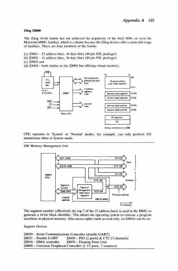
Zilog Z8000
The Zilog 16-bit family hasnot achieved the popularity of the Intel XO!lo. or even the Motorola 681Klll. families. which is a shame because the Zilog devices offer a powerful range of facilities. There arc four members of the family:
(a) Z81Kll - 23 address lines. 16 data lines (48-pin DIL package): (b) Z81Kl2- 16 address lines. 16 data lines (40-pin DIL package): (c) Z81Kl3 and (d) Z81Kl4- both similar to the Z81Kil but offering virtual memory.
15
16 multiplexed address and data 14 accumulators lines and index registers
7 address segmen.t lines Normal stack segment
System stack segment
0 RO
R13
R14N
R145
Control lines Normal stack pointer R 15N
System stack pointer R 155
48-pin OIL
PC segment
PC
Similar mnemonics to ZBO
CPU operates in 'System' or 'Normal' modes. for example. can only perform 110 instructions when in System mode.
ZBO Memory Management Unit
A A07-AOO
; A015-A08
I Z8001 CPU
Segment A number
"' Table of
SN6-SNO 64segment
" v descriptor registers
Logical address
I I
II
A15-A8 I ~Add
A23-A8 I
Z8010MMU
"' 07-00 r ..
015-08
~ A7-AO
y
A
-"'
~· )
-} A23-A8)
f r
Physical addr ess
-To memory
The segment number (effectively the top 7 of the 23 address lines) is used in the MMU to generate a 16-bit block identifier. This allows the operating system to relocate a program anywhere in physical memory. Also access rights (such as read-only. no DMA) can be set.
Support Devices
Z8030- Serial Communications Controller (doublc-UART) Z81l31- Doublc-UART Z81136- PIO (2 ports) & CTC (3 channels) Z81ll6- DMA controller Z81l70- Floating Point Unit Z81l90- Universal Peripheral Controller (2 1/2 ports. 2 counters)

196 Microcomputer Fault-finding and Design
Motorola 68000
Very powerful 16-bit processor, with 32-bit registers. Easy to use, program and interface. There are four family members:
(a) MC68000- 24 address lines, 16 data lines (used in Apple Macintosh); (b) MC68008- 20 address lnes, 8 data lines (used in Sinclair QL); (c) MC68010- as MC68000, with 'virtual memory'; (d) MC68200- single-chip 68000 (with ROM, RAM, UART, timers).
D
CLK gen.
CLK = 4-12.5 MHz
IPL2.
MC68000
24 address lines
16 data
"lines
Control lines
~Coded 16M byte address range interrupts Uses memory mapped 1/0 Used in many UNIX systems
31
8 data registers
7 address registers
User stack pointer
Supervisor SP
PC
0
I~ AO to A6
A7
Status reg.
A status flag indicates if the CPU is in 'System' or 'User' mode. In System mode, certain privileged instructions can be used. Only 56 basic mnemonics in the instruction set. A 16-bit opcode with 3 bits specifying register number. 14 addressing modes.
Interrupts
Possesses 256 'exceptions' (interrupts), including software interrupts. First 1K of memory contains 256 vectors, for example, contents of 4 memory locations (bytes) are placed in PC on interrupt.
Application
Using 8-bit support devices:
MC88000
Tx}To Rx VDU
Support Devices
MC68451 - Memory Manager MC68450- DMA Controller
Appendix A 197
32-bit Microprocesson
Advantages over 16-bit devices: ( 1 gigabyte = 1 OOOM bytes)
(1) 32-bit data manipulation (integer range -231 to +231 -1); (2) larger memory addressing range (232 = 4 gigabytes); (3) faster operation (clock speeds 16 MHz to 25 MHz)- typically '})3 times faster than 16-bit
CPUs; (4) extra instructions and addressing modes; (5) built-in memory management (convert logical address to physical address, and provide
memory protection); (6) instruction/data cache (on-chip memory holding most frequently addressed instructions
and data items).
NMOS or CMOS devices in 84- to 114-pin chip carrier packages. Machine code compatible with their 16-bit predecessors.
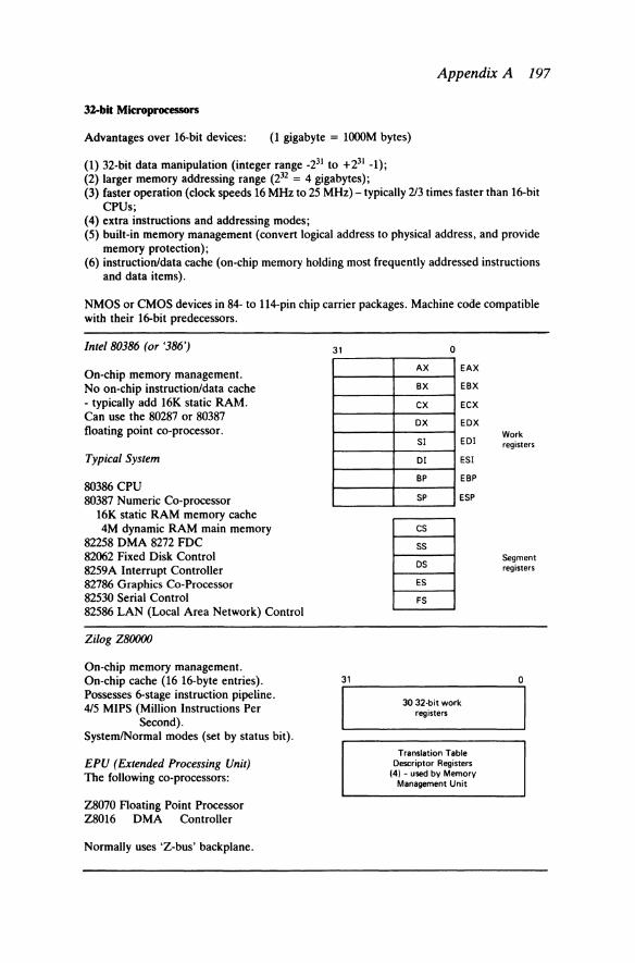
/nte/80386 (or '386')
On-chip memory management. No on-chip instruction/data cache - typically add 16K static RAM. Can use the 80287 or 80387 floating point co-processor.
Typical System
80386 CPU 80387 Numeric Co-processor
16K static RAM memory cache 4M dynamic RAM main memory
82258 DMA 8272 FDC 82062 Fixed Disk Control 8259A Interrupt Controller 82786 Graphics Co-Processor 82530 Serial Control 82586 LAN (Local Area Network) Control
Zilog Z80000
On-chip memory management. On-chip cache (16 16-byte entries). Possesses 6-stage instruction pipeline. 415 MIPS (Million Instructions Per
Second). System/Normal modes (set by status bit).
EPU (Extended Processing Unit) The following co-processors:
Z8070 Floating Point Processor Z8016 DMA Controller
Normally uses 'Z-bus' backplane.
31
31
0
AX EAX
BX EBX
ex ECX
ox EDX
Sl EDI
01 ESI
BP EBP
SP ESP
cs ss OS
ES
FS
30 32·bit work registers
Translation Table Descriptor Registers
(4) - used by Memory Management Unit
Work registers
Segment registers
0
198 Microcomputer Fault-finding and Design
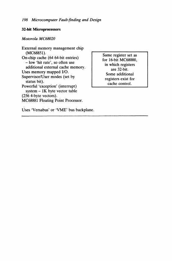
32-bit Microprocessors
Motorola MC68020
External memory management chip (MC68851).
On-chip cache (64 64-bit entries) - low 'hit rate', so often use additional external cache memory.
Uses memory mapped 110. Supervisor/User modes (set by
status bit). Powerful 'exception' (interrupt)
system - lK byte vector table (256 4-byte vectors). MC68881 Floating Point Processor.
Uses 'Versabus' or 'VME' bus backplane.
Same register set as for 16-bit MC68000,
in which registers are 32-bit.
Some additional registers exist for
cache control.

Appendix A 199
lnmos Transputer
The transputer (the name is an amalgam of 'transistor' and ·computer") is an example of a RISC (Reduced Instruction Set Computer). It possesses a small instruction set and single-cycle operation. and therefore it is extremely fast in operation ( 10 MIPS). Several transputers arc arranged in arrays to achieve parallel processing or ·concurrency·.
Memory 1nterface
Programmed in a high-level language. ·occam·.
CPUs
!~14
4serodllonks e.lch 10.MIJIIS Sf'COnd lc~lled
channelf)
(I) T414- 32-hit. 4 serial links. 2K RAM (sec ahovc). (2) T424- 32-hit. 4 serial links. 4K RAM. (3) T212- lt\-hit. 4 serial links. 2K RAM. (4) T!\00- 32-hit. 4 serial links. on-chip floating point proc.
Supporting Devices
(I) F424 floating point transputer. (2) G412 graphics controller transputer. (3) M212 disk controller transputer. (4) COOl and C002 link adaptors (to produce !\-hit parallel link).
Transplller Arrays
Large transputer arrays can rival mainframe computers in processing power. usc a transputer array for the CPU function in their latest machines.
In fact. ICL
A typical M (!\ x !I) array. in which the program is distrihuted throughout the transputers in order to accelerate its execution.
Program sections transfer data via the serial links.
~----::q ~-----w
I : I \ I : I I I I I I I I I 1 I t
~----~ Ll--LJ-----u
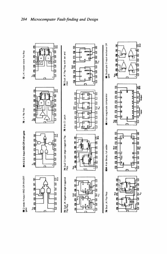
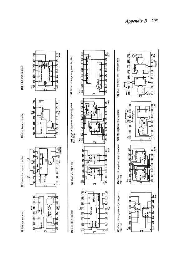
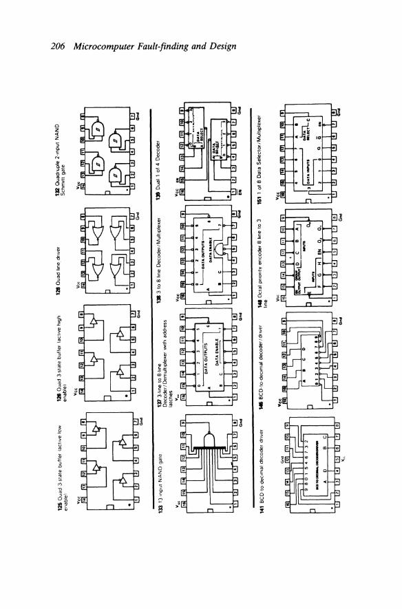
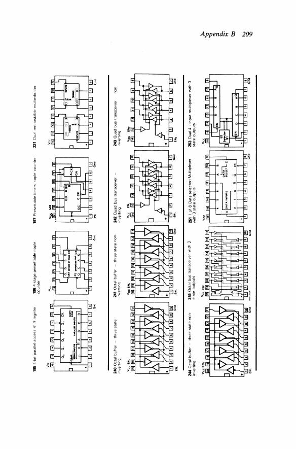
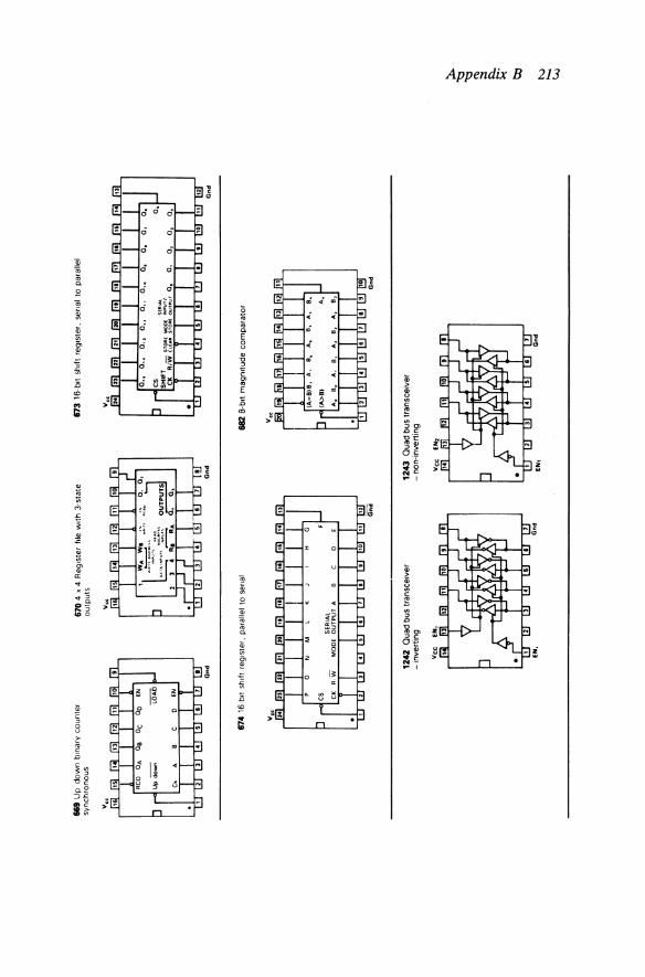
Appendix B: Pin Functions of TTL Digital Integrated Circuits
The serial number of each integrated circuit is
SN74XY
where XY is the two- or three-digit number listed for each device. There are several families of these TTL (Transistor Transistor Logic)
devices, and the most common is the
SN74LSOO
family. 'LS' stands for 'Low-power Schottky'.
The material presented in this Appendix is copyright RS Components Limited, Corby, Northants, and reproduced with permission.
200

00 Q
ua
dru
ple
2-l
np
ut
NA
ND
ga
te
Gnd
04 H
ex m
vert
er
Gnd
08
Qu
ad
rup
le 2
-mp
ut
AN
D g
ate G
nd
01 Q
ua
dru
ple
2-1
nput
NA
ND
ga
te
w1t
h o
pe
n c
olle
c10r
ou
tpu
t
v'
Gnd
05 H
ex I
nve
rte
r-o
pe
n c
olle
cto
r o
utp
uts
Gnd
09 Q
uad
2-tn
pu't-
AN
D g
ate-
open
co
llect
or
ou
tpu
ts
v.,
....
02
Qu
ad
rup
le 2
-1np
ut N
OR
ga
te G
nd
06 H
ex
1nve
rter
w1t
h h1
gh v
olt
ag
e
op
en
co
llect
or
ou
tpu
t
Gnd
10 T
riple
3-t
nput
NA
ND
gat
e
Gnd
03
Qu
ad
rup
le 2
-1np
ut N
AN
D g
ate
-
op
en
co
llect
or
mp
uts
Gnd
07
Hex
dr1
ver
w1t
h o
pe
n c
olle
cto
r o
utp
ut
v,
Gnd
11 T
riple
3-t
nput
AN
D g
ate
Gnd
::t:. :g ""' ;:::
$:l..
~·
0, ~

13 D
ual
4-in
put
NA
ND
gat
e S
chm
itt
trig
ger
20 D
ual 4
-inpu
t N
AN
D g
ate
Gnd
2li Q
uad
2-in
put
NA
ND
buf
fer-
open
co
llect
or o
utpu
ts
v"
Gn
d
14 H
ex S
chm
itt T
rigge
r
Vee
a ...
21 D
ual
4-in
put
AN
D g
ate
v,,
Gn
d
'D T
riple
3-in
put
NO
R g
ate
Gnd
1& T
riple
3-
inpu
t A
ND
gat
e -
open
co
llect
or
ou
tpu
ts
... 22
Dua
l 4-
inpu
t N
AN
D g
ate
-op
en
cone
ctor
out
puts
Gn
d
21 Q
uad
2-in
put
NO
R b
uffe
r
Vee
Gnd
11 H
ex I
nver
ter
With
ope
n co
llect
or
ou
tpu
t
2li D
ual 4-
~npu
t N
OR
gat
e w
ith
stro
be
311 8
-inp
ut N
AN
D g
ate
Gn
d
N ~
ft
~- a 8 ~ ~ ~ ~
~
;::s ~
~- § ~
t::::l
~ <§'

3Z Q
uadr
uple
2-in
put
OR
gat
e
40 D
ual
4-in
put
NA
ND
buf
fer
49 B
CD
-to-
7 se
gmen
t de
code
r I d
river
v.
Gn
d
Qn
d
33 Q
uad
2-in
put
NO
R b
uffe
r-op
en
colle
ctor
out
puts
Gnd
42 B
CD
-to-
deci
mal
dec
oder
Qn
d
Qn
d
49 B
CD
-to-
7-se
gmen
t de
code
r /dr
iver
-op
en c
olle
ctor
o
utp
uts
Gnd
:rt Q
uadr
uple
2-in
put
NA
ND
buf
fer
Ve
e
Gn
d
4li
BC
D-t
o de
cim
al d
eco
de
r/d
nve
r
Gnd
51 D
ual
2-w
ide
2-~n
put/
3-in
put
AN
D-O
R-I
NV
ER
T g
ate
Vee
Gnd
38 Q
uadr
uple
2-in
put
NA
ND
buf
fer
-o
pen
co
llect
or
ou
tpu
ts
Vee
lf1 B
CD
-to-
7 se
gmen
t d
eco
der
/dri
ver
-op
en c
olle
ctor
ou
tput
s
64 3
-2-2
-3 i
nput
AN
D-O
R-I
NV
ER
T
ga
te
v"
Gnd
~
~ ~ !:l...
~- 1:1::1
N fZ
• 2-
wid
e 4-
inpu
t A
ND
-OR
-IN
VE
RT
ga
te
Gnd
n D
ual
JK n
egat
ive
edge
-trig
gere
d F
lip-F
lop
v"
78 D
ual
JK F
lip-F
lop
GOd
v"
14 4-
2-3-
2-In
put A
ND
-OR
inve
rt g
ate
70
J-K
flip
-flo
p
""'
G""
74 D
ual
D-t
ype
edge
-trig
gere
d Fl
ip-
71 4
-bit
0 La
tch
Flo
p
v~
83A
4-b
it B
inar
y fu
ll ad
der
• 4-
bit
mag
nit
ud
e co
mp
arat
or
Gnd
72 J
-K m
aste
r-sl
ave
flip-
flop
71 D
ual
JK F
lop-
Flop
wit
h s
et a
nd
clea
r
v~
• Q
uad
rup
le 2
-mp
ut
excl
usi
ve O
R
gate
Qnd
~ :::: r:;- ~ 8 ~ ;:: ~ "'' ~ ;:: :::;:-~
;:s ~
~- l:l ;:s ~
t::;,
~
~ ;:s
90 D
ecad
e co
un
ter
Gnd
Vee
96 5
-blt
shill
reg
1ste
r
113
Dua
l JK
neg
at1v
e ed
ge t
ng
ge
red
F
lip-F
lop
Gnd
92 D
IVId
e-by
-tw
elve
co
un
ter
93 4
-blt
b1na
rv c
ou
nte
r Gnd
Vee
M
R I
CL
EA
RI
Vee
IN
PU
TS
107
Dua
l JK
Flip
-Flo
p 10
9 D
ual
JK p
os1t
1ve
edge
-tr1
gger
ed
Fltp
Flo
p
v"
114
Dua
l JK
neg
at1v
e ed
ge-t
r1gg
ered
12
1 M
on
ost
ab
le m
ult1
v1br
ator
Fh
p· F
lop
v"
Gnd
958
4-bl
t sh
1ft
reg1
s!er
Voo
Gnd
112
Dua
l JK
ed
ge
tn
gg
ere
d f
hp
-flo
p
123
Dua
l m
on
ost
ab
le -
retn
gg
era
ble
TIM
ING
•
c ::t..
:g ~ $::)...
~·
tx:l
N ~
125
Qua
d 3-
stat
e b
uff
er
lact
•ve
low
en
able
l
Gn
d
133
13 m
pu
t N
AN
D g
ate
v ..
141
BC
D-to
dec
tmal
dt!
code
r dr
~ver
v"
126
Oua
d 3-
stat
e bu
ffer
lac
t•ve
h•g
h en
able
J
Vee
128
Oua
d hn
e_ d
rtve
r
Gn
d
Gn
d
137
3-hn
e to
8-h
ne
138
3 to
8 l
ine
Dec
oder
I M
ult1
plex
er
De
cod
er/
De
mu
ltip
lexe
r w
1th
addr
ess
latc
hes . ..
Gn
d
146
BCD
-to-
deC
imal
dec
oder
/du
ver
148
Oct
al p
no
nty
enc
oder
8 h
ne t
o 3
hn
e V«
132
Qua
drup
le 2~r
nput
N
AN
D
Sch
m1t
t g
ate
138
Dua
l 1
of
4 D
ecod
er
161
1 of
8 D
ata
Se
lect
or/
Mu
ltip
lexe
r Gn
d
tv
~
~
;::;· c:l 8 ~ ;:: ~ .... ~
;:: ~ ~ s· ~ ~- § ~
\:::1
~
~-

163
Dua
l 4-
hne
to 1
-hne
Dat
a S
ele
cto
rs: M
ultip
lexe
rs
Vee
A
SH
lCT
ft S
lllC
T
114
4 to
16
l•ne
Dec
oder
Gn
d
161
Dua
l 1-
ol-4
De
cod
er:
Dem
ultip
lexe
r 1&
7 Q
uad
2 to
1-h
ne D
ata
Sel
ecto
rs
w1t
h op
en c
olle
cto
r o
utp
uts
I M
ultip
lexe
rs
EN
Gn
d
181
Bin
ary
coun
ter
-as
ynch
rono
us
rese
t
Gn
d
112
BC
D c
ou
nte
r -
syn
chro
no
u!i
rese
t
Gn
d
15
6 D
ual
1 o
f 4
Dec
oder
:' D
emul
tiple
xer
168
Qua
d 2
to l
-Im
e D
ata
sele
ctor
st M
ulti
ple
xers
w1t
h In
vert
ed
o
utp
uts
183
B1n
ary
cou
nte
r -
syn
chro
no
us
rese
t
Gn
d
160
BC
D d
ecad
e co
un
ter
-a
syn
chro
no
us
rese
t
Gn
d
164
Sen
al-1
n pa
ralle
l-ou
t sh
1ft
reg•
ster
Gn
d
Gn
d
~ :g ~ ~
~- b::l ~
'-I

1• 8-
b•t pa
ral~
el to
sen
al c
onve
rter
1
89
4-S
tage
syn
chro
nous
bi
dire
ctio
nal c
ount
er
174
Hex
D-t
ype
Flip
-Flo
ps
Yoo
Gnd
,.,
Par
ity g
ener
ator
/ch
eck
er
9-b•
t o
dd
/eve
n
192
Up
/Do
wn
dec
ade
coun
ter
-w
ith p
rese
t in
pu
ts
Gnd
G"d
181
4-b•
t an
thm
et•c
log
•c u
n•t
113
Up
/ Dow
n b1
nary
co
un
ter-
w1
th
pres
et i
nput
s
Vee
""'
Gn
d
175
Qua
d D
-typ
e F
lip-F
lops
Gnd
191
Btn
ary
syn
chro
no
us
up
/do
wn
co
un
ter
OU
TP
UT
S
'---
--'
INII
'UT
S
194
A 4
-blt
bld
ue
ctio
na
l un
iver
sal
sh1f
t re
g1st
er
Gnd
Gnd
Gnd
N ~
~
~- 8 ~ ;:: ~ ... 2l ;:: ::::;-~ s· ~ ~- !:
) ;:s ~
tl
~
~-
195
4-b•
t pa
ralle
l-acc
ess
shtft
reg
tste
r
v"
240
Oct
al b
uffe
r -
thre
e st
ate
tnve
rttn
g
EN,
244
Oct
al b
uff
er
-th
ree
stat
e n
on
in
vert
ing
EN,
Gn
d
1• 4-s
tage
pre
setta
ble
nppl
e co
unte
r
Gn
d
241
Oct
al b
uffe
r --
thre
e st
ate
non
tnve
rttn
g
245
Oct
al b
us t
rans
ceiv
er w
1th
3 st
afe
ou
tpu
ts
Vee
EN
Gn
d
191
Pre
sett
able
btn
arv
nppl
e co
un
ler
MA
242
Qua
d bu
s tra
nsce
1ver
-
.nve
rt.n
g
Gn
d
251
1 o
f 8
Dat
a se
lect
or/
Mu
ltip
lexe
r w
ith
3 s
tate
ou
tpu
ts
221
Dua
l m
on
osl
ab
le r
null•
v•br
.ttor
Gnd
243
Qua
d bu
s tr
ansc
etve
r no
n tn
vert
tng
EN1
Gn
d
253
Dua
l 4
-tn
put
mul
tiple
xer
With
3
stat
e o
utp
uts
~
~ ~ 1::1.
~- l::l::l ~

2li6
Dua
l 4-
bit
addr
essa
ble
latc
h
AD
DR
ES
S
INPU
TS
Gnd
286
Qu
ad
2-i
nput
Exc
lusi
ve N
OR
ga
te
298
Qua
d 2
-po
rt r
eg•s
ter
(Qua
d 2-
inp
ut
mul
ttpl
exer
With
sto
rage
)
v ••
Gnd
2&7
Oua
d 2
-mp
ut
mu
lttp
lexe
r w
tth
3 st
ate
ou
tpu
ts
SE
LEC
T
273
8-bt
t re
gtst
er w
tth c
lear
Vee
291
8-bt
t-un
iver
sal
shif
t /s
tora
ge
re
gist
er W
ith c
omm
on p
aral
lel
I/O
pm
s 3
stat
e v •
•
Gnd
Gnd
Gnd
2S8
Ou
ad
2-t
np
ut
mu
lttp
lexe
r w
tth
3
sta
te o
utp
uts
Gnd
28
0 9
-Bit
pari
ty g
ener
ator
/che
cker
v"
Gnd
321
Cry
stal
co
ntr
olle
d o
scill
ato
r
v ••
v ••
Gn
d2
2&9
8-bt
t ad
dres
sabl
e la
tch
28
3 4
-btt
btn
ary
full
ad
de
r
323
8-bt
t un
tver
sal
shif
t/st
ora
ge
re
gist
er w
tth
syn
chro
nous
res
et a
nd
com
mon
II 0
pm
s 3
stat
e v,
.
Gnd
Gnd
tv
....... ~
~
;::;·
~ 8 ~ $:: ~ ~
$:: :::;:-~ s· ~ ~·
!::>
;: ~
tl
~ ac;·
;:

a2
Dua
l 4
-in
pu
t m
ultip
lexe
r in
vert
ing
v ..
311
He
x 3
stat
e b
uff
er
no
n-i
r.ve
rtin
g
373
Oct
al t
rans
pare
nt l
atch
wit
h 3
st
ate
ou
tpu
ts
Ond
363
Dua
l 4-
inpu
t m
ult
iple
xer
with
3
stat
e o
utp
uts
inv
ertin
g
v,,
-H
ex 3
sta
te b
uff
er
inve
rtin
g
37
4 O
cta
l 0-t
ype
flip
-flo
p w
ith
3
stat
e o
utp
uts
Vee
Gn
d
3154
8-
line
to
1-lin
e da
ta
sele
ctor
/mul
tiple
xer/
regi
ster
v,.
387
Hex
3-s
tate
bu
tte
r
377
Oct
al
D-t
ype
fli
p-flo
p w
ith e
mib
le
iN
GN
D
351
8-lin
e to
1-
line
data
se
lect
or/m
ultip
lexe
r/re
gist
er
v,.
.. H
ex
3-st
ate
inve
rte
r b
uff
er
!sep
arat
e 2-
bit
& 4
-bit
sec
tions
)
EN
37
8 H
ex
D r
egis
ter
Gn
d
~
~ .,. ;:::
! ~
~- tl:l
una
N
......
......

311
4-B
it ar
ithm
etic
logi
c un
it
319
Qua
d 2-
part
regi
ster
120
Oct
al b
us t
rans
ceiv
er
v"
Gnd
390
Dua
l de
cade
cou
nter
Gn
d
442,
443
, 44
4 Q
uad
tridi
rect
1ona
l bu
s tr
ansc
eive
rs 3
sta
te
Gnd
825
Vol
tage
con
trol
led
osci
llato
r
v ..
v"
393
Dua
l4
stag
e bi
nary
co
un
ter
Gn
d
673
Oct
al 0
-typ
e t
rans
pare
nt l
atc
h
1140
Tri-
stat
e,
inve
rtin
g oc
tal
bus
tran
scei
ver
395
4-b
it ca
scad
able
shi
ft r
egis
ter
3 st
ate
Gn
d
S.
Oct
al 0
-typ
e t
rans
pare
nt l
atch
in
vert
ed o
utp
uts
v ..
843
Tri-s
tate
, tr
ue
and
inve
rtin
g oc
tal
bus
tran
scei
ver
N .......
N ~
~- (") 0 .§ -=:: ~
..... ~
-=:: ~ ~ s· ~ ~·
;:,
;:::: ~
t:l
;:; <§'
a U
p d
ow
n b
1nar
y co
unte
r sy
nchr
onou
s
Gnd
170
4 x
4 A
eg1s
ter
f1le
w1t
h 3-
stat
e ou
tput
s
174
16-b
•t sh
1ft
reg1
ster
. pa
ralle
l to
ser~al
1242
Qua
d bu
s tr
ansc
eive
r -i
nve
rtin
g
EN,
Gnd
Gnd
173
16-b
•t s
h1ft
reg•
ster
. se
nal
to p
aral
lel
Gnd
682
8-b1
t m
agn1
tude
co
mp
ara
tor
v"
1243
Qua
d bu
s tr
ansc
eive
r -
non-
inve
rtin
g
EN
t
~
~ ~ $::),.
><
· t::!:
l
~
v..
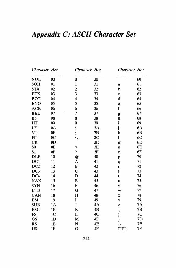
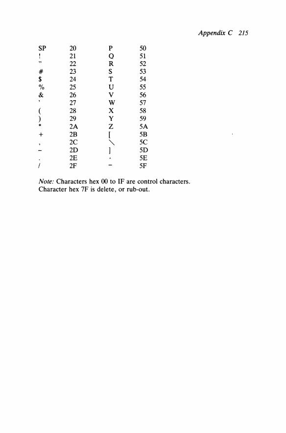
Appendix C: ASCII Character Set
Character Hex Character Hex Character Hex
NUL ()() 0 30 60 SOH 01 1 31 a 61 STX 02 2 32 b 62 ETX 03 3 33 c 63 EOT 04 4 34 d 64 ENQ 05 5 35 e 65 ACK 06 6 36 f 66 BEL 07 7 37 g 67 BS 08 8 38 h 68 HT 09 9 39 69 LF OA 3A j 6A VT OB 3B k 6B FF oc < 3C l 6C CR OD 3D m 6D so OE > 3E n 6E S1 OF ? 3F 0 6F DLE 10 @ 40 p 70 DC1 11 A 41 q 71 DC2 12 B 42 r 72 DC3 13 c 43 s 73 DC4 14 D 44 t 74 NAK 15 E 45 u 75 SYN 16 F 46 v 76 ETB 17 G 47 w 77 CAN 18 H 48 X 78 EM 19 I 49 y 79 SUB 1A J 4A z 7A ESC 1B K 4B { 7B FS 1C L 4C I 7C I
GS 1D M 4D } 7D RS 1E N 4E 7E us 1F 0 4F DEL 7F
214
Appendix C 215
SP 20 p 50 21 Q 51 22 R 52
# 23 s 53 $ 24 T 54 % 25 u 55 & 26 v 56
27 w 57 ( 28 X 58 ) 29 y 59 * 2A z SA + 2B [ SB
2C " sc 20 ] 50 2E SE
I 2F SF
Note: Characters hex 00 to IF are control characters. Character hex 7F is delete, or rub-out.

Appendix D: Examples (for Chapters 1 to 8 - Fault-finding)
(1) What is the cause of the fault in a +5 V power supply that causes +8.5 V to appear at the output pins?
(2) Mechanical faults are far more common than electronic faults in the IBM PC computer. Write notes to justify this statement.
(3) Describe how you would use a logic probe and logic pulser to test an 8-bit buffer on the Address bus of a computer.
(4) (a) For what purpose would you use a pencil eraser in a computer fault-finding situation?
(b) How would you use a cooling spray to help to locate a fault that appears 10 minutes after switch-on?
(5) A floppy disk-based computer boots successfully. However all operating system commands that require program files to be transferred from disk produce the following message on the CRT:
DISK TRANSFER FAILURE
Suggest two possible causes of this fault. ( 6) Suggest a single cause for each of the following faults:
(a) all Address bus and data bus lines are permanently floating; (b) the waveform observed on A 7 is identical at all times to that on
A6; (c) bytes can be read in from a PIO and UART, but no bytes can
be output to these devices; (d) an IBM PC boots successfully, but a disk read error is reported
when it attempts to enter the word processor program. (7) Describe any faults that can be detected by sight (no test equipment is
to be used) in a microcomputer circuit board. (8) A microcomputer will not boot when switched on or the Reset is
pressed. Describe how you would test the Reset circuit using a CRO. (9) If a NOP free-run test works correctly, but a debug EPROM
containing the single instruction:
216
Appendix D 217
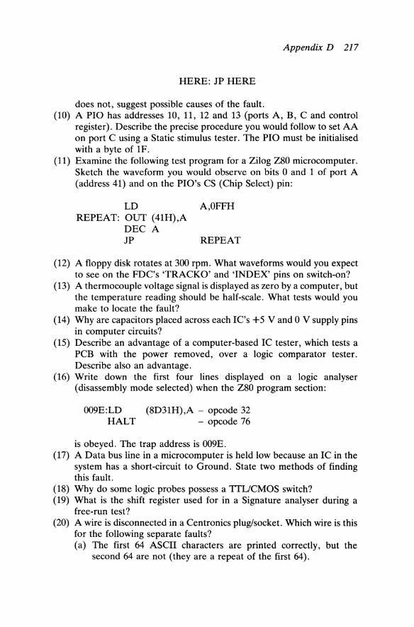
HERE: JP HERE
does not, suggest possible causes of the fault. (10) A PIO has addresses 10, 11, 12 and 13 (ports A, B, C and control
register). Describe the precise procedure you would follow to set AA on port C using a Static stimulus tester. The PIO must be initialised with a byte of 1F.
(11) Examine the following test program for a Zilog Z80 microcomputer. Sketch the waveform you would observe on bits 0 and 1 of port A (address 41) and on the PIO's CS (Chip Select) pin:
LD A,OFFH REPEAT: OUT (41H),A
DEC A JP REPEAT
(12) A floppy disk rotates at 300 rpm. What waveforms would you expect to see on the FDC's 'TRACKO' and 'INDEX' pins on switch-on?
(13) A thermocouple voltage signal is displayed as zero by a computer, but the temperature reading should be half-scale. What tests would you make to locate the fault?
(14) Why are capacitors placed across each IC's +5 V and 0 V supply pins in computer circuits?
(15) Describe an advantage of a computer-based IC tester, which tests a PCB with the power removed, over a logic comparator tester. Describe also an advantage.
(16) Write down the first four lines displayed on a logic analyser (disassembly mode selected) when the Z80 program section:
009E:LD HALT
(8D31H),A - opcode 32 - opcode 76
is obeyed. The trap address is 009E. (17) A Data bus line in a microcomputer is held low because an IC in the
system has a short-circuit to Ground. State two methods of finding this fault.
(18) Why do some logic probes possess a TTL/CMOS switch? (19) What is the shift register used for in a Signature analyser during a
free-run test? (20) A wire is disconnected in a Centronics plug/socket. Which wire is this
for the following separate faults? (a) The first 64 ASCII characters are printed correctly, but the
second 64 are not (they are a repeat of the first 64).

218 Microcomputer Fault-finding and Design
(b) The first character in a string of characters is printed correctly, the next 9 are missing, and so on.
(21) A faulty microprocessor circuit board is holding the +5 V de supply at +2 V. (a) Suggest causes of this fault. (b) How would you attempt to locate the fault?
(22) Examine the circuit shown on page 219. Sketch the waveforms you would expect to see with a CRO on the signals numbered 1 to 9. (Assume that each bus transfer takes 1 microsecond.)

;;;
N/C
RE
SE
T
CP
U
(650
2)
(J)
HO
LD
(DE
MA
RE
Q)
®-A
15 a
nd
®RtW
w
hen
2000
: JP
200
0 is
obe
yed
<D P
ort
A; b
it 0
whe
n th
e fo
llow
ing
is o
beye
d:
LOO
P:
LD
A,5
5H
OU
T
(PIO
PO
RT
A),
A
LD
A,O
AA
H
OU
T
(PIO
PO
RT
A),
A
JP
LOO
P
@ H
ead
step
(as
sum
e he
ad i
nitia
lly o
ver
Tra
ck 2
) w
hen
the
follo
win
g is
obe
yed:
LD
A
,7
OU
T
(TR
AC
K),
A
Tx Ax :::)
@ T
x an
d @
RT
S w
hen
the
follo
win
g is
obe
yed:
LD
A
,43
H
OU
T
(UA
RT
TX
), A
A
ssum
e E
ven
Par
ity,
7 D
ata
bits
, 1
Sto
p bi
t
~
~ "' ;::! ~ ~·
tl
N
.......
\0

Glossary
Accumulator. A special CPU register that receives the results of most ALU operations.
ADC. Analogue-to-digital converter. Address bus. The microcomputer bus that carries the memory address of
the instruction that is being fetched, or a data item that is being transferred between the CPU and memory or input/output.
Address decoder. A circuit that generates chip select signals for each memory or input/output chip within a microcomputer.
Addressing mode. A method of specifying the location of a data item that is being accessed within an instruction.
ALU. Arithmetic and Logic Unit. The module within the CPU that performs arithmetic, for example add and subtract, and logic, for example AND and OR operations.
Analogue. A continuous signal that can take any value over its range. AND. The Boolean logic function that generates logic 1 only if both
comparison (or input) bits are also at logic 1. Application program. A program in a disk-based computer that tailors the
machine to a specific commercial/scientific function, for example word processor, spreadsheet, database, payroll.
ASCII. American Standard Code for Information Interchange. The code that is used to represent characters in computers, printers and VDUs.
ASIC. Application Specific Integrated Circuit. An /C that is designed to perform a single powerful function, for example a digital signal processor.
Assembler. A program that converts an assembly language program into machine code.
Assembly language. A programming language that is line-for-line convertible to machine code, but uses mnemonics for the instruction type ('opcode') and labels for memory addresses.
Audio cassette recorder. A domestic tape recorder that is used to store microcomputer programs.
Backing store. A bulk storage device, for example floppy disk or hard disk, for programs and data files.
220

Glossary 221
BASIC. Beginners All-purpose Symbolic Instruction Code. The most popular high-level language that is used with microcomputers.
Baud rate. The speed of transmission of serial data expressed in bits/second.
BCD. Binary Coded Decimal. A 4-bit code that represents the numbers 0 to 9.
Binary. A number system that uses the base of 2. The only symbols used in binary nu'fubers are 0 and 1.
Bistable. Two-state. A 'bistable multivibrator', or 'flip-flop', holds either logic 0 or logic 1.
Bit. Binary digit. A bit has two states - 0 and 1. Boolean logic. A collection of logic functions named after George Boole.
The Boolean logic functions AND, OR and Exclusive-OR are applied by software on binary numbers in computers.
Bootstrap. A program that loads the main program (normally the 'operating system,') from backing store into memory when the computer is switched on.
Bounce. Unwanted repeated operation of a mechanical contact. Branch. As for jump. Breakpoint. A stop that is inserted into a program to assist in the testing of
a new or faulty program. Buffer. A temporary storage register. Bug. A software error. Burst memory transfer. A continuous DMA transfer. Bus. A set of signal connections that have a common function. A
microcomputer possesses an address bus, data bus and control bus. Byte. Eight bits.
Cache. A fast memory circuit that is placed between the CPU (or on the CPU) and its memory circuit (normally dynamic RAM). It stores the most frequently addressed locations.
Call. An instruction that transfers program control to a subroutine. Carry flag. A bit in a CPU status register which indicates that the result of
an ALU operation has exceeded the number range of the ALU. Central Processor Unit. See CPU. Centronics interface. The international standard for the signal interface
between a computer and a parallel-drive printer. Checksum. A number that is placed after a list of data values in order to
provide a means of confirming that the data list is read correctly. Chequerboard pattern. An alternating bit pattern of 101010, etc., used to
test various computer devices. Chip. A common name for an integrated circuit.

222 Microcomputer Fault-finding and Design
Chip carrier. An /C package that uses the four sides of the device for interconnecting pins - used for devices with a large number of interconnecting pins.
Chip select. A control signal that activates a memory or input/output chip. CMOS. Complementary Metal Oxide Semiconductor. A family of
integrated circuits that offers extremely high packing density and low power consumption.
Common bus. A set of interfacing connections that allows microcomputer boards to be interconnected. Examples are the Versabus, S-100 bus and VME bus.
Compiler. A program that converts a high-level language program into machine code before program run-time and stores both versions on backing store.
Complement. Change a bit from 1 to 0 or 0 to 1. Computer. A programmable data processing system. Concurrency. The execution of more than one function by a computer at
the same time, for example parallel processing with more than one CPU.
Control register. The register in a programmable input/output device, for example UART, P/0, CTC or FDC, that is used to select the programmable options within the device.
Control unit. The module within the CPU that examines and implements the current instruction.
Counter/timer. See CTC. CPU. Central Processor unit. The main computer module, which fetches
and implements program instructions. Its main sub-modules are the ALU and control unit. In a microcomputer, the CPU normally forms a single /C and is called a microprocessor.
CRO. Cathode Ray Oscilloscope. An item of test equipment that displays signal waveforms on a CRT.
CTC. Counter/Timer Circuit. A programmable input/output circuit that can be used to generate timer interrupt pulses, generate time delays or count external pulses. A CTC is either contained within a P/0 chip, or it constitutes a separate chip.
Current tracer. A hand-held item of test equipment that detects changing current levels by electromagnetic induction.
Cursor. A small area of light on a CRT screen (part of a VDU) at which characters which are entered by the operator will appear.
DAC. Digital-to-analogue converter. Daisy-chain. A connection system in which signal connections are linked
from one module to another. Data. A general term that can describe numbers, characters or groups of
bits suitable for processing by computer program.
Glossary 223
Data bus. The microcomputer bus that carries data (and program instructions) between CPU and memory or input/output.
Debugger. A test program that is used to locate and eliminate errors (or bugs) in a program under development.
Denary. The decimal number system that uses a base of 10. Diagnostic. A test program that exercises parts of the hardware
configuration to confirm correct operation. Digit. Each symbol in a number system, for example a binary digit can be 0
or 1. Digital. Possessing discrete states. Computers operate using binary signals,
that is possessing only two states. DIL. Dual-in-line. The standard /C package, in which interconnecting pins
are placed along the two long sides of the rectangular device. Directory. A list of all the filenames in a computer with a backing store. DMA. Direct Memory Access. Data transfer between memory and
input/output without passing through the CPU. Dot matrix. A method of constructing characters using an array of dots, for
example CRTIVDU and printer. DVM. Digital voltmeter. An item of test equipment that displays voltage,
current and resistance readings numerically. Dynamic RAM. RAM memory that requires a regular refresh operation to
prevent corruption of stored bit pattern.
Editor. A program that allows the operator to enter or amend a text file. EPROM. Erasable Programmable Read Only Memory. ROM that can be
erased by exposure to ultra-violet light and then re-programmed. Exception. An alternative name for interrupt used by some microprocessor
manufacturers. Exclusive-OR. The Boolean logic function that generates logic 1 only if
both comparison bits are different.
FDC. Floppy Disk Controller. A programmable input/output chip that controls a floppy disk drive.
FET. Field Effect Transistor. The principal component in MOS and CMOS circuits.
Fetch. The first part in the fetch-execute cycle which is implemented when the CPU obeys an instruction.
Fetch-execute cycle, The basic cycle that is implemented by the CPU when it obeys an instruction. Firstly the instruction is fetched from memory and secondly it is examined by the control unit and executed.
File. A program or data module held on backing store. Firmware. Program or data resident in ROM. Flag. A bit that indicates a specific condition or event.

224 Microcomputer Fault-finding and Design
Floating point. A number representation system for large and fractional numbers - the number is split into mantissa and exponent.
Floppy disk. A backing store medium that employs flexible magnetic disks. Flowchart. The diagrammatic representation of the operation of a
program. Format. To initialise a blank floppy disk (or hard disk). Free-run. To allow the kernel of a computer circuit to run in test mode -
the CPU is forced continually to obey a single instruction.
Gate. A digital circuit with more than one input, but only one output. Gates perform Boolean logic functions.
GPIB. General Purpose Interface Bus. An alternative name for the IEEE488 common bus.
Hard disk. A backing store medium that employs a non-removable hard disk. A hard disk is faster, more expensive and possesses larger storage capacity than a floppy disk. It is often called a 'Winchester' disk.
Hardware. The physical equipment in a computer (to be distinguished from software).
Hexadecimal. A number system that uses a base of 16. Its particular use is to represent long binary numbers in an abbreviated form.
High-level language. A programming language that is similar to spoken language. A high-level language program must be converted to machine code before it is executed in a computer.
Hit rate. The success rate of locating the contents of a memory location in a cache.
IC. Integrated circuit. In-circuit emulator. A combined hardware and software system that is used
in a MDS to test a new microprocessor-based product. Initialise. To set up an input/output chip, for example a PIO, UART, CTC
or FDC, to one of its programmable states. Input port. A circuit that passes external digital signals (normally 8) into a
CPU. Input/output. The hardware within a computer that connects the computer
to external peripherals and devices. Instruction. A single operation performed by a computer. A low-level
language program consists of a list of instructions. Integrated circuit. A circuit package that contains several components built
into the same semiconductor wafer. This silicon wafer is housed in either a DIL or chip carrier.
Interactive. The characteristic of a program that asks the operator questions during the implementation of the program.

Glossary 225
Interface. The circuit and interconnection system between a computer and its external devices.
Interpreter. A program that converts a high-/eve/language program into machine code at run-time, rather than prior to run-time (see compiler).
Interrupt. An external signal (part of the CPU's control bus) that suspends a program operating within a computer and causes entry into a special interrupt program. The latter is normally named an interrupt service routine.
Interrupt service routine. A program that is entered following an interrupt.
Jump. An instruction that sends program control to a specified memory location.
K. A symbol that represents decimal 1024. Kansas standard. A signal specification for data storage on audio cassette
recorders. Kernel. The central circuit within a computer, that is CPU, clock circuit,
Reset circuit and any bus buffers.
Label. A name given to a memory location in an assembly language program.
Language. A prescribed set of characters and symbols which is used to convey a program to a computer. A programming language can be a high-/eve/language or a low-/eve/language.
Latch. A circuit that staticises bits. LED. Light Emitting Diode. A diode that emits light when current passes
through it. It is often used in a LED segment display unit or for single-bit indication.
Loader. A program that converts a 'printable' version of a machine code program into executable machine code.
Logic. The application of a range of circuit building blocks to perform switching and control functions.
Logic analyser. An item of test equipment used for testing digital electronic systems, for example computers. A CRT is used to display information recorded from the system under test.
Logic comparator~ A test board that monitors a digital IC and indicates if it produces different output signals to a reference IC.
Logic level. The voltage value that is used to indicate logic 0 or 1. For TTL and TTL-compatible circuits (including most microprocessors and their support chips) logic 0 = 0 V, and logic 1 = +5 V.
Logic monitor. A clip that is placed over a digital IC and indicates on LEDs the logic level at each pin.
Logic probe. A hand-held item of test equipment that indicates logic levels using LEDs.
226 Microcomputer Fault-finding and Design
Logic pulser. A hand-held item of test equipment that injects pulses into a system under test.
Loop. A section of program that is executed more than once. Low-levellanguage. A computer programming language that specifies each
operation/instruction that the CPU is to perform. There are two classifications of low level language: assembly language and machine code.
M. A symbol that represents approximately a million (1 048 576). See also K.
Machine code. A program expressed in binary form, that is in the way in which it is executed within the CPU.
Mail. Messages that can be passed between users on a multi-user computer system.
Main memory. Fast memory which holds the program currently being executed. Main memory can be ROM, RAM or a mixture of the two.
Mainframe computer. A large multi-user computer with high processing power and a wide range of peripherals. Typical applications are for payroll, large customer accounts systems, large database applications.
Matrix printer. A printer that constructs characters using a dot matrix. MDS. Microprocessor Development System. A computer that is used to
develop software for prototype microcomputer applications. Memory. Any circuit or peripheral that staticises data. Normally the term is
used in place of main memory. Memory management. A circuit (sometimes part of the CPU in the case of
32-bit microprocessors) that can modify the address generated by the CPU.
Memory map. A diagrammatic representation of the organisation of the memory range of a computer.
Memory mapped input/output. Input/output devices that are treated by hardware and software as memory devices.
Microcomputer. A complete computer on a handful of integrated circuits (or even a single integrated circuit). VLSI components are used for CPU, memory and input/output.
Microprocessor. A CPU constructed on a single VLSI integrated circuit. Minicomputer. An arbitrary name given to a multi-user computer that
performs down-market applications to a mainframe computer. Minicomputers are used extensively for industrial control applications. They are normally 16-bit machines.
Mnemonic. A group of letters (or symbols) that is used to represent the function of an instruction expressed in assembly language form.
Modem. An item of equipment that converts logic levels to frequencies, and vice versa. It is used for serial communication systems that pass through the public telephone network.
Glossary 227
Monitor. The main program in some microcomputers. MOS. Metal Oxide Semiconductor. A family of integrated circuits that
offers high packing density (VLSI). Most microprocessors and their supporting memory and input/output chips are constructed using MOS technology.
Multiplexing. The technique of passing more than one signal along a single conductor.
Nesting. A program loop within another loop. Alternatively a subroutine within another subroutine.
NOP. No-operation. A program instruction that performs no processing, but simply uses some CPU time.
Nybble. 4 bits.
Object code. The name given to a machine code version of a program. The term is used to distinguish this version from the source program, which is assembly language or high-level language.
Opcode. The part of a machine code instruction that specifies the function of the instruction, for example add, shift, jump.
Operand. The part of a machine code instruction that specifies the data value or its memory address.
Operating system. The main program in a disk-based computer. OR. The Boolean logic function that generates logic 1 if either of the
comparison (or input) bits is set to logic 1. Output port. A circuit that passes digital signals (normally a group of 8
parallel bits) outside a microcomputer.
Parity. The number, expressed as odd or even, of logic ls in a data value. Pascal. A high-level language. PCB. Printed Circuit Board. A conventional circuit board with etched
copper track interconnections between components. Peripheral. An item of equipment that is external to a computer, for
example printer, VDU, floppy disk. PIO. Parallel Input/Output. A programmable multi-port input/output chip. Pipeline. A small storage area within some CPUs that hold the next few
instructions to be obeyed - the instructions are read out of memory before they are required in order to increase program execution speed.
Pixel. A dot position on a CRT screen. PLA. Programmable Logic Array. An IC that consists of an array of logic
gates that can be programmed to perform an overall logic function by the operator.
Poll. Regularly to check the status of an external signal or device by software.

228 Microcomputer Fault-finding and Design
Port. An input or output parallel-connection channel between a computer and external equipment. Normally a port is 8-bits wide.
Program. A set of processing steps that a computer's CPU is required to perform.
Program counter. A CPU register that holds the address in memory of the next instruction to be obeyed.
PROM. Programmable Read Only Memory. ROM that is programmed after the chip is manufactured. Once programmed it cannot be altered.
Pseudo-instruction. An instruction in an assembly language program that acts as a command to the assembler and is not converted to machine code.
RAM. Random Access Memory. RAM is semiconductor read/write memory. It is misnamed because ROM is also random access. There are two classifications of RAM: static RAM and dynamic RAM.
Read. To transfer data from memory to the CPU. Refresh. To reinstate data in dynamic RAM or displayed on a segment
display or CRT. Register. A storage device for several bits. A microprocessor contains
several work registers, as well as special-function registers. Return. An instruction that returns program control to a main program
from a subroutine or interrupt service routine. RISC. Reduced Instruction Set Computer. A CPU that possesses only a
limited instruction set in order to achieve high-speed performance. An example is the transputer.
ROM. Read Only Memory. ROM is semiconductor memory which can only be read from. There are three classifications of ROM: ROM (bit pattern stored is set when chip is manufactured), PROM and EPROM.
RS232-C. The internationally recognised specification for serial data transfer between computers and serial-drive peripherals (or other computers).
SBC. Single Board Computer. Segment. An area of memory - typically 64K in several 16-bit
microprocessor systems. Segment display. A display that constructs numbers and letters by a
network of segments. Semiconductor memory. ROM and RAM. Serial. The transfer of data items by setting one bit at a time on a single
conductor. Shift. Transfer of data to the left or right (normally within a register). Software. Computer programs and data files. Source program. The name given to an assembly language or high-level
language version of a program. ·

Glossary 229
Stack. A reserved area of memory (must be RAM) that is \!Sed by most microprocessors to store the return address in subroutines and interrupt service routines.
Static RAM. Conventional RAM, unlike dynamic RAM which requires refreshing.
Static stimulus tester (SST). A device that is used to test a microcomputer board. The CPU is removed from the board under test and signals from the SST are injected into the CPU's bus connections in order to test memory and input/output devices.
Status register. A collection of flag bits in a microprocessor that indicates the state of the ALU.
Subroutine. A section of program that is separated from the main program, but can be called several times from the main program.
SUT. System Under Test. System program. The operating system or a utility program that supports
the operating system, for example editor, compiler, assembler.
Tag address. The address of a memory location that is held in a cache. Transputer. A microprocessor family produced by Inmos. Transputer
arrays are designed to perform the CPU function in high-speed computer systems.
Tristate. A circuit in which its outputs can be set into one of three states: logic 0, logic 1 or 'floating' (high impedance, that is electrically isolated).
TTL. Transistor Transistor Logic. A family of integrated circuits that preceded MOS and CMOS, but is still widely used for gates, buffers, flip-flops ( bistables), etc.
TTY. Teletype. A name sometimes given to a printer Two's complement. A binary numbering system used to represent both
positive and negative numbers- the most significant bit acts as a sign bit.
UART. Universal Asynchronous Receiver Transmitter. An input/output chip that handles serial data transfer, for example to VDU, printer or other computer. The RS232-C interface is generated by the device.
Utility program. A program that supports an operating system, for example a compiler, editor, assembler, etc.
VDU. Visual Display Unit. An operator device that includes a CRT for display purposes and a keyboard for manual entry. It is invariably connected to a computer by serial RS232-C link.
Vector. Part (or all) of a memory address that contains the start address of an interrupt service routine.

230 Microcomputer Fault-finding and Design
VLSI. Very Large Scale Integration. A measure of the packing density of an integrated circuit (more than 1000 gates per chip). Used as a description of MOS and CMOS devices.
Volatile memory. Memory that loses its stored bit pattern when power is removed.
VRAM. Video RAM. RAM that is used to store video data.
Winchester. Another name for a hard disk. Word. A unit of data in a computer. The word length is the same as the bit
length of the CPU, for example microprocessors are expressed as 8-bit, 16-bit or 32-bit devices.
Word processor. A program that is used to create and amend text files, for example letters, reports, source programs.
Write. To transfer data to memory from the CPU. Write protect. To set a backing store device to read-only to protect against
file over-writing.
Index
ADC (Analogue to Digital Converter) 140, 161
Address bus 1 Address decoding 7 ALU (Arithmetic and Logic Unit) 5 Assembly language 4 ATE (Automatic Test Equipment) 46 Audio cassette recorder 75
BASIC 58,61 Bootstrap loader 149 Byte 2
Cache 179, 197 Capture 91 Centronics interface 63, 68, 118 Character generator 108 Checksum 51, 54 Chequerboard test 56 Chip carrier 2 Cleaning spray 39 Compiler 99 Computer-based tester 46 Concurrency 199 Control bus 1, 26 Control register 14, 15 Control unit 5 Co-processor 18, 180, 193 CRO (Cathode Ray Oscilloscope) 23 CRT (Cathode Ray Tube) 17, 51, 108 Crystal 24 CTC (Counter Timer Circuit) 14 Current tracer 42
Daisy chain 187 Daisy wheel printer 69 Data bus 1 Data pointer 5 Debug ROM/EPROM 35 Disassembly 90 Diskette 71
DMA (Direct Memory Access) 7, 14, 26, 166
DOS (Disk Operating System) 98 DVM (Digital Voltmeter) 61, 139 Dynamic RAM 11
Editor 99 EPROM 11, 97, 128 Exclusive-OR gate 46
FDC (Floppy Disk Controller) 14, 71, 151
Fetch-execute cycle 4, 36 Floating point 19, 181 Floating signals 17 Floppy disk 71 Flowchart 55 Free-run test 26, 83, 92
GPIB bus 95
Handshaking 14, 141 Head 73 Hexadecimal 2
In-circuit emulator 96 Inmos transputer 199 Input/output 15, 59 Instruction register 5 Intel microprocessors 185, 191, 192 Interrupts 5, 24, 111, 163
Kansas standard 76 Kernel 26 Keyboard encoder 111
LED (Light Emitting Diode) 23, 41 Loader 99 Logic analyser 85 Logic comparator 46 Logic monitor 45
231

232 Index·
Logic probe 40 Logic pulser 40
Machine code 4 Matrix printer 69, 117 MDS (Microprocessor Development
System) 98 Memory 11 Memory management 195 Memory map 9, 91 Menu 53 Microbus analyser 94 Microcomputer 2 Microcontroller 191 Micro-floppy 71 Microprocessor 2, 184 Modem 64 Monitor program 50, 52 MOS (Metal Oxide Semiconductor)
16 MOS Technology microprocessors
188 Motorola microprocessors 190, 198 Multimeter 22 Multiplex 15, 158
NOP (No-Operation) test 26, 83
Opcode 4 Open collector 33 Open-circuit fault 38 Operand 4
PC (Personal Computer) 149, 172 PIO (Parallel Input/Output) 14, 59,
120, 132, 141, 159 Port 15, 58 Power supply 20 Printer 68, 117 Program counter 5 PROM 11 Pulse stretching 41 Pushbutton 15
RAM 11,84
Register 5 Relocate 100 Reset 5, 23, 25, 149 Return 17 ROM 11,84 RS232-C 14, 63, 108 RTC (Real-Time Clock) 152
Schmitt trigger 41 Sector 73 Serial link 14, 17 Short-circuit fault 38, 44 Signature analysis 79 Speech synthesiser 141 Stack 17 Stack pointer 17 Static RAM 11 Static stimulus test 30 Stepper motor 73, 117 Subroutine 17, 111 Switched mode power supply 22
Trace 100 Transformer 21 Trigger 91 Truth table 9 TTL devices 200
UART (Universal Asynchronous Receiver Transmitter) 14, 67, 110
UNIX 98
VDU (Visual Display Unit) 17, 37, 63, 106
Video RAM 106 Virtual memory 194 VLSI (Very Large Scale Integration)
16
Winchester 75 Word 2
Zilog microprocessors 26, 186, 191, 195