Embed Size (px)
Citation preview

APP-012 MCS-8 Six Board Class Structure Definition
APP-012 6 Board Class Structure.doc 1
Micro Control SystemsAPPLICATION NOTEAPP-012
Six Board Class Definitions
Revision History
Date Author Description
9/8/98 R Toney App note created based upon App note 011

APP-012 MCS-8 Six Board Class Structure Definition
APP-012 6 Board Class Structure.doc 2
TheoryThis app note documents all class structures for a six board system. App note 11contains class structures for a four board system. These two app notes togetherwith app note 7 provide complete documentation of the MCS network protocol forboth the MCS-8 RS232 and RS485 communication ports.
Class Definitions
Index
Index ................................................................................................................................... 2General definitions: ............................................................................................................. 3
Indexes: ........................................................................................................................... 3Character:........................................................................................................................ 4Byte: ................................................................................................................................ 4Integer: ............................................................................................................................ 4Long:................................................................................................................................ 5Unsigned long:................................................................................................................. 5Unsigned integer: ............................................................................................................ 5Time:................................................................................................................................ 6Arrays that are not classes: ............................................................................................. 6
Class #0 BEGIN EEPROM.................................................................................................. 7Class #1 VERSION NUMBER EEPROM ............................................................................ 7Class #2 CHILLER EEPROM.............................................................................................. 8Class #3 RO EEPROM ..................................................................................................... 13Class #4 AO EEPROM...................................................................................................... 14Class #5 SI EEPROM ....................................................................................................... 14
Sensor name & characteristic array............................................................................... 15Class #6 SETPOINT EEPROM......................................................................................... 17Class #7 MACHINE EEPROM .......................................................................................... 18Class #8 RESERVED........................................................................................................ 19Class #9 AUTH EEPROM................................................................................................. 19Class #10 HISTORY EEPROM......................................................................................... 20Class #11 RTC EEPROM ................................................................................................. 20Class #12 RESERVED...................................................................................................... 21Class #13 RESERVED...................................................................................................... 21Class #14 RESERVED...................................................................................................... 21Class #15 OPERATING SCHEDULE EEPROM ............................................................... 21Class #16 RESERVED...................................................................................................... 23Class #17 RESERVED...................................................................................................... 23Class #18 RESERVED...................................................................................................... 23Class #19 RESERVED...................................................................................................... 23Class #20 RESERVED...................................................................................................... 23

APP-012 MCS-8 Six Board Class Structure Definition
APP-012 6 Board Class Structure.doc 3
Class #21 END EEPROM ................................................................................................. 23Class #22 CHECKSUM EEPROM .................................................................................... 24Class #23 CHILLER RAM ................................................................................................. 25
Capacity control state name array ................................................................................. 27Circuit control state name array..................................................................................... 27Valve control state name array ...................................................................................... 28
Class #24 RO RAM STATUS............................................................................................ 28Class #25 RO RAM INFO ................................................................................................. 29Class #26 AO RAM STATUS ............................................................................................ 30Class #27 AO RAM INFO.................................................................................................. 30Class #28 SI RAM STATUS.............................................................................................. 31
Analog input sensor ....................................................................................................... 31Digital input sensor ........................................................................................................ 31
Class #29 SI RAM INFO ................................................................................................... 31Class #30 MCSIO RAM..................................................................................................... 32Class #31 SW STATUS .................................................................................................... 34Class #32 SPARE ............................................................................................................. 35Class #33 ALARM HISTORY............................................................................................ 35
System Alarm name array ............................................................................................. 36Class #34 MACHINE RAM................................................................................................ 38Class #35 RTC RAM......................................................................................................... 38Class #36 SW TIME RAM................................................................................................. 39Class #37 SPARE ............................................................................................................. 39Class #38 HISTORY POINTERS ...................................................................................... 39Class #39 HISTORY RAM ................................................................................................ 40Class #40 RAM BEG MARK ............................................................................................. 41Class #41 RAM CFG MARK ............................................................................................. 41Class #42 RAM END MARK ............................................................................................. 41Class #43 RAM AD RAW .................................................................................................. 42Class #44 SPARE ............................................................................................................. 42Class #45 RAM ALGO FILTERED .................................................................................... 42Class #46 RAM OUTPUT IMAGE ..................................................................................... 43Class #47 RS232 RAM ..................................................................................................... 43Class #48 RS485 RAM ..................................................................................................... 44Class #49 SETPOINT RAM .............................................................................................. 45Class #50 METER RAM.................................................................................................... 45Class #51 METER HISTORY............................................................................................ 45Class #52 RESERVED...................................................................................................... 45Class #53 RO RAM EXTRA.............................................................................................. 45Class #54 LOCKOUT HISTORY RAM .............................................................................. 46
General definitions:
Indexes:• Fields that contain indexes to relay outputs, analog outputs, sensor inputs or set
points contain relative pointers (0 points to the first entry) into the associated
APP-012 MCS-8 Six Board Class Structure Definition
APP-012 6 Board Class Structure.doc 4
class array or 255 if that field is not used. A valid index, not 255, must be lessthan the maximum number of entries for that array. These are hexadecimalnumbers.• Examples:
• An index into either the relay output or sensor input arrays will be anumber from 0 to 31 decimal or 0 to 1F hexadecimal.
• An index into the set point array will be a number from 0 to 59 decimal or0 to 3B hexadecimal.
Character:• Fields defined as a character, CHAR, contain ASCII formatted characters.
• Examples:• The Manufacturer’s name that is in location 17-32 of the VERSION
NUMBER EEPROM class will be stored as an array of characters that areterminated by a NULL (00) character:
(1st line = location, 2nd = ASCII characters and the 3rd = hexadecimal value)1 2 3 4 5 6 7 8 9 10 11 12 13 14 15 16M I C R O C O N T R O L4D 49 43 52 4F 20 43 4F 4E 54 52 4F 4C 20 20 00
Byte:• Fields defined as a byte, BYTE, contain a value from 0 to 255 decimal or 0 to FF
hexadecimal. These are only positive numbers and there are no decimal places.• Examples:
• 9 will be stored as a 9• 16 will be stored as a 10• 254 will be stored as a FE
Integer:• Fields defined as an integer, INT contains a decimal number in the range of
negative 32767 to positive 32767. This defines a signed integer that is a wholenumber, all decimal places are assumed. This type of definition requires twopositions. The number is stored with low value in the first position and its highvalue in the second position.
DecimalValue
# ofdecimalplaces
Asprinted
Asstored
Hexa-decimal
Storedas
10 0 10 10 10 10 0010 1 10 100 64 64 00
489 1 48.9 489 1E9 E9 01201 2 201 20100 4E84 84 4e
-1568 0 -1568 -1568 F9E0 E0 F9-32767 0 -32767 -32767 FFFF FF FF

APP-012 MCS-8 Six Board Class Structure Definition
APP-012 6 Board Class Structure.doc 5
Long:
• Fields defined as long, Long, contain a decimal number in the range of negative2,147,483,648 to positive 2,147,483,647. This defines an integer that is a signedwhole number, all decimal places are assumed. This type of definition requiresfour positions. The number is stored with low value in the first position and itshigh value in the second position.
Decimal Value Hexadecimal Stored as
Unsigned long:• Fields defined as unsigned long, Ulong contain a decimal number in the range of
0 to positive 4,294,967,295. This defines an integer that is a positive wholenumber, all decimal places are assumed. This type of definition requires fourpositions. The number is stored with low value in the first position and its highvalue in the fourth position.
Decimal Value Hexadecimal Stored as
Unsigned integer:• Fields defined as unsigned integer, Word, a decimal number in the range of 0 to
positive 65535. This defines an integer that is a positive whole number, alldecimal places are assumed. This type of definition requires two positions. Thenumber is stored with low value in the first position and its high value in thesecond position.
Decimal Value Hexadecimal Stored as10 10 10 00
489 1E9 E9 0132767 7FF FF 0765534 FFFE FE FF

APP-012 MCS-8 Six Board Class Structure Definition
APP-012 6 Board Class Structure.doc 6
Time:• Fields defined as HHMMSS contain a time value. These fields define the time
as: hour, minute, second. This definition requires 3 positions, 1 for each item.• Examples:
• The time 10:39:58 AM will be stored as hexadecimal 0A 27 38 in the 3positions.
• The time 2:15:28 PM will be stored as hexadecimal 0E 0F 1C in the 3positions. Remember, time is stored as military time; therefore, the 2 PMbecome 14 which is a E in hexadecimal.
Arrays that are not classes:The following four arrays must be built:
• Sensor name & characteristic array. This array will contain the sensorname, e.g. MCS-T100; character to be displayed, e.g. F; and number ofassumed decimal places, e.g. 1. Indexes in the Sensor and Set Pointclasses will point to this array. Refer to SI EEPROM Class #5 for adefinition of this array.
• System alarm names. This array will contain the alarm name. Refer toAlarm History Class #33 for a definition of this array.
• Capacity control state names. This array will contain the alarm name.Refer to Chiller Ram Class #23 for a definition of this array.
• Circuit control state names. This array will contain the alarm name. Referto Chiller Ram Class #23 for a definition of this array.

APP-012 MCS-8 Six Board Class Structure Definition
APP-012 6 Board Class Structure.doc 7
Class #0 BEGIN EEPROMRecord size: 16Number of records in the class: 1Total array size: 16
This class contains the visual identification of the beginning of the EEROM area, theconfiguration data. This class contains fixed data, that is it is not changed in the PC-Config program or in a live unit.
Field definitions
Location Type Description1-15 Char “*BEGINNING CFG*”16 Byte Filler of 00
Class #1 VERSION NUMBER EEPROM
Record size: 80Number of records in the class: 1Total array size: 80
This class contains base information about the unit such as manufacturer, modelnumber, date installed as well as the name of this configuration file. This informationis displayed under the UNIT INFORMATION option of the SERVICEDIAGNOSTICS menu. Fields are build by the PC-Config program.
Field definitions
Location Type Description1-16 Char Unit’s identification, displayed in Unit Information. This is an
alpha-numeric field of a maximum of 15 characters plus anull character.
17-32 Char Company name, displayed in Unit Information & in SYSTEMI.D. screens. This is an alpha-numeric field of a maximum of15 characters plus a null character.
33-48 Char Model identification, displayed in Unit Information & inSYSTEM I.D. screens. This is an alpha-numeric field of amaximum of 15 characters plus a null character.
49-51 MMDDYY
Date of system installation, displayed in Unit Information & inSYSTEM I.D. screens.
52-67 Char Units serial number. This is an alpha-numeric field of amaximum of 15 characters plus a null character.

APP-012 MCS-8 Six Board Class Structure Definition
APP-012 6 Board Class Structure.doc 8
68 Byte Version number of the configuration file that is being workedon. A 4 indicates a 4 board or a 6 board system. This fieldwill always be a 6.
69 Byte This field indicates the type of configuration file that is beingworked on. Presently there are only two types ofconfiguration files that are supported in the 6 board system.
• 2 = Heatcraft,• 110 = Pump Control.
Base on this field, the PC-CONFIG program will display adifferent screen for the base information screen.
70 Byte PC-CONFIG will automatically place current month in thisfield. Value is stored as a hexadecimal number
71 Byte PC-CONFIG will automatically place current day of month inthis field. Value is stored as a hexadecimal number
72 Byte PC-CONFIG will automatically place current year in this field.Value is stored as a hexadecimal number
73 Byte PC-CONFIG will automatically place current hour in this field.Value is stored as a hexadecimal number
74 Byte PC-CONFIG will automatically place current minute in thisfield. Value is stored as a hexadecimal number
75 Byte PC-CONFIG will automatically place current month in thisfield. Value is stored as a hexadecimal number
76 Byte PC-CONFIG will automatically place current day of month inthis field. Value is stored as a hexadecimal number
77 Byte PC-CONFIG will automatically place current year in this field.Value is stored as a hexadecimal number
78 Byte PC-CONFIG will automatically place current hour in this field.Value is stored as a hexadecimal number
79 Byte PC-CONFIG will automatically place current minute in thisfield. Value is stored as a hexadecimal number
80 Byte Some of the applications support a model number, this willbe stored in this field as a hexadecimal value.
Class #2 CHILLER EEPROM
Record size: 320Number of records in the class: 1Total array size: 320
This class contains information that ties the RO’S and SI’S to various functions.E.G. flow switch location. The options are contained in this class. The format andcontain of this class vary depending on the type of configuration file, see location 69of Class #1, VERSION NUMBER EEPROM.
Field definitions for Heatcraft configuration file:

APP-012 MCS-8 Six Board Class Structure Definition
APP-012 6 Board Class Structure.doc 9
Location Type DescriptionLocations 1-32 apply to base information about thesystem.
1 Byte Type of refrigeration that is being use. This field is notused at this time.
2 Byte Type of compressor(s) that are on the system.• 1 = Reciprocating• 2 = Reciprocating with out oil control• 3 = Screw• 4 = Scroll• 5 = Hitachi screw• 6 = Bitzer screw• 7 = Variable speed
3 Byte Type of condenser that is on the system.• 0 = No condenser• 1 = Common air• 2 = Individual air per circuit• 3 = Combined air, circuits 1 & 3 share the same
condenser while circuits 2 & 4 share the samecondenser.
• 4 = Common water• 5 = Individual water
4 Byte Type of evaporator that is on the system. This field is notused at this time.
5 Byte The number of refrigeration cycles. Number can be from1to 6.
6 Byte Phase loss, Index point to sensor input that indicatesphase loss for the entire system. If not used, then it is255.
7 Byte Ambient temperature, Index point to sensor input that isreading the ambient temperature. If not used, then it is255.
8 Byte Leaving liquid temperature, Index point to sensor inputthat is reading the leaving liquid temperature. If not used,then it is 255.
9 Byte Entering liquid temperature, Index point to sensor inputthat is reading the entering liquid temperature. If not used,then it is 255.
10 Byte Condenser flow switch, Index point to sensor input thatprovides a digit input when there is flow. If not used, thenit is 255.
11 Byte Water flow switch, Index point to sensor input thatprovides digit input when there is flow swtich. If not used,then it is 255.

APP-012 MCS-8 Six Board Class Structure Definition
APP-012 6 Board Class Structure.doc 10
12 Byte True: Perform pump down when the compressor isstarted.False: DONOT perform pump down when the compressoris started.
13 Byte True: If an I/O board is lost, then lock out the system.False: If an I/O board is lost, do not lock out the system,keep the system running.An alarm will always be generated.
14 Byte Option that specifies whether the control is on returningliquid, field will be a 1, else control will be on leavingliquid.
15 Byte Field is not used at this time. Filler of 255.16 Byte Option anti cycle timer. If true, the system will start the
anti cycle timer when the compressor is turned on. Elseanti cycle timer when the compressor is turned off.
17 Byte Field is not used at this time.18 Byte Field is not used at this time.19 Byte Emergency Stop indicator, Index point to sensor input that
provides a digit input when the system is to stop runningimmediately. If not used, then it is 255.
20 Byte Count of the total number of steps in the system. This canbe a number from 1, single compressor single circuit, to16, 4 circuits with a compressor and 3 unloaders or 2unloaders and hot gas bypass on each circuit.
21 Byte Count of the total number of condenser steps if a commoncondenser has been specified. If not used, then field is 0.
22 Byte First relay output of condenser points for a commoncondenser, Index point to relay output. Note condenserpoints must be consecutive. If not used, then it is 255.
23 Byte Run Stop indicator, Index point to sensor input thatprovides a digit input when the system is allowed to run. Ifnot used, then it is 255.
24 Byte Alarm relay output, Index point to relay output. This pointwill be turn on when an alarm is generated. If not used,then it is 255.
25 Byte Sensor input for current limit option.26 Byte Sensor input for kw limit option.27 Byte Relay output that is turned on when a low ambient shut
down exists.28 Byte Field is not used at this time.29 Byte Option for continuous pump down. If true, continuous
pump down will be active. That is when the compressor isoff the suction pressure will be checked. If high, thecompressor will be turned on to reduce the suctionpressure. If false, then the suction pressure will not becheck when the compressor is off.

APP-012 MCS-8 Six Board Class Structure Definition
APP-012 6 Board Class Structure.doc 11
30 Byte Temperature target reset, Index point to sensor input thatwill provide an adjustment to the temperature target. If notused, then it is 255.
31 Byte Option for lead/lag control. If true, the system willautomatically change the lead circuit. If false, then circuit1 will always be the lead.
32 Byte Sensor input that provides voltage.33-80 THESE FIELDS APPLY TO CIRCUIT #1 (THEY WILL
BE REPEATED FOR CIRCUITS 2, 3, 4, 5 & 6 )33 Byte • 0 =34 Byte Number of compressor stages. Compressor, unloaders,
hot gas bypass and liquid line solenoid are included in thiscount.
35 Byte First compressor relay output point, Index point to relayoutput. Compressor points for this circuit must beconsecutive. If not used, then it is 255.
36 Byte Number of condenser stages associated with this circuit,not common condenser.
37 Byte First condenser relay output point, Index point to relayoutput. Condenser points for this circuit must beconsecutive. If not used, then it is 255.
38 Byte Field is not used at this time. Filler of 255.39 Byte Field is not used at this time. Filler of 255.40 Byte Suction pressure, Index point to sensor input that will
provide:• if a pressure transducer, suction pressure or• if a digital input, an on condition when a low
suction pressure condition is encountered.If not used, then it is 255.
41 Byte Discharge pressure, Index point to sensor input that willprovide:
• if a pressure transducer, discharge pressure or• if a digital input, an on condition when a high
discharge pressure condition is encountered.If not used, then it is 255.
42 Byte Suction temperature, Index point to sensor input that willprovide suction temperature. If not used, then it is 255.
43 Byte Discharge temperature, Index point to sensor input thatwill provide discharge temperature. If not used, then it is255.
44 Byte Oil pressure, Index point to sensor input that will provide:• if a pressure transducer, oil pressure or• if a digital input, an on condition when a low oil
pressure condition is encountered.If not used, then it is 255.
45 Byte Oil temperature, Index point to sensor input that willprovide oil temperature. If not used, then it is 255.

APP-012 MCS-8 Six Board Class Structure Definition
APP-012 6 Board Class Structure.doc 12
46 Byte Compressor Amps, Index point to sensor input that willprovide:
• if a amp sensor, compressor amp draw or• if a digital input, an on condition when a high
compressor amp draw condition is encountered.If not used, then it is 255.
47 Byte Motor fault, Index point to sensor input that will provide adigital input. When on some type of compressor fault hasoccurred. If not used, then it is 255.
48 Byte Field is not used at this time. Filler of 255.49 Byte Field is not used at this time. Filler of 255.50 Byte Field is not used at this time. Filler of 255.51 Byte Field is not used at this time. Filler of 255.52 Byte Field is not used at this time. Filler of 255.53 Byte Field is not used at this time. Filler of 255.54 Byte Field is not used at this time. Filler of 255.55 Byte Field is not used at this time. Filler of 255.56 Byte Field is not used at this time. Filler of 255.57 Byte Field is not used at this time. Filler of 255.58 Byte Field is not used at this time. Filler of 255.59 Byte Type of valve for the evaporator:
0 = Liquid Line Soleniod 1 = Pulsed expansion valve 2 = 4-20 ma expansion valve 255 = none
60 Byte Option for hot gas bypass. If true, a hot gas bypass existsfor this circuit. An RO index pointer is not required ascompressor points must be in a fixed sequence.
61 Byte Number 1 to 4, indicates the number of compressors thatare on this circuit.
62 Byte Number 0,1 or 2, indicates the number of unloaders thatare on each compressor.
63 Byte Motor Oil Pressure, Index point to sensor input that willprovide motor oil pressure. If not used, then it is 255.
64 Byte Phase Loss, Index point to digital input that when onindicates a phase loss condition. If not used, then it is255.
65 Byte Pump down, Index point to sensor input that indicates thecircuit must be pumped and moved to an off state if it isalready on or if off remain off. If not used, then it is 255.
66 Byte Water flow switch for this circuit only, Index point tosensor input that provides a digit input when there is flow.If not used, then it is 255.
67 Byte Option for part winding starter. If true, two RO arerequired to start the compressor, this must be included inthe point count of number of compressor stages.
APP-012 MCS-8 Six Board Class Structure Definition
APP-012 6 Board Class Structure.doc 13
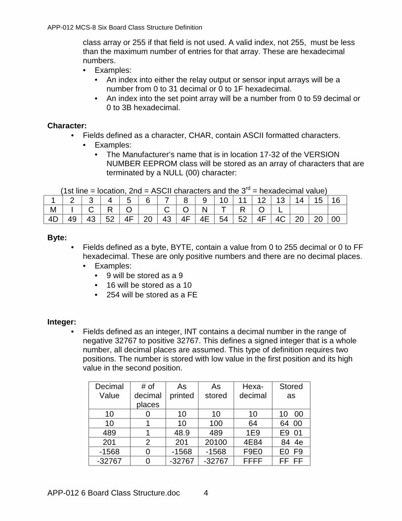
68 Byte Compressor proof indicator, Index point to sensor inputthat provides a digit input when the associatedcompressor is on. If not used, then it is 255.
69 Byte If True, then control a oil flow solenoid.70 Byte If True, then control a liquid injection solenoid.71 Byte Relay output that is turned on when this circuit is in a anti-
cycle state.72 Byte Condenser Water flow switch for this circuit only, Index
point to sensor input that provides a digit input when thereis flow. If not used, then it is 255.
73 Byte Leaving liquid temperature for this circuit only, Index pointto sensor input that provides a the temperature of theleaving liquid for this circuit. If not used, then it is 255.
74 Byte Pointer to the expansion valve. This can be either a RO orAO depending on the type of valve.
75-80 Bytes This is for filler only.81-128 THESE FIELDS APPLY TO CIRCUIT #2 (They are the
same fields as defined above)129-176 THESE FIELDS APPLY TO CIRCUIT #3 (They are the
same fields as defined above)177-224 THESE FIELDS APPLY TO CIRCUIT #4 (They are the
same fields as defined above)225-272 THESE FIELDS APPLY TO CIRCUIT #5 (They are the
same fields as defined above)272-320 THESE FIELDS APPLY TO CIRCUIT #6 (They are the
same fields as defined above)
Class #3 RO EEPROM
Record size: 32Number of records in the class: 48Total array size: 1536
This class contains describes the individual relay outputs and their characteristics.Fields are build by the PC-Config program.
Field definitions
Location Type Description1-8 byte Up to an 8 character alpha-numeric name.
8-16 byte Filler, null characters, 00 hexadecimal.17 byte Indicate if relay is inverted, field is a 1, or a 0 if relay is not
inverted.

APP-012 MCS-8 Six Board Class Structure Definition
APP-012 6 Board Class Structure.doc 14
18 byte Display text19 byte Field is not used.20 byte Key pad type.21 byte This field is used for pulsed output. If non-pulsed that is on or
off output the field is 0. For pulsed output such as electronicexpansion valves, each count is equal to 1/10 of a secondduration when the relay is on.
22-32 byte Filler, not used.
Class #4 AO EEPROM
Record size: 32Number of records in the class: 12Total array size: 384
This class contains describes the individual analog output names. Fields are buildby the PC-Config program.
Field definitions
Location Type Description1-8 Byte Up to an 8 character alpha-numeric name.
9-32 Byte Filler, this are is not used.
Class #5 SI EEPROM
Record size: 32Number of records in the class: 48Total array size: 1536
This class contains describes the individual sensor inputs and their characteristics.Fields are build by the PC-Config program.
Field definitions
Location Type Description1-8 Char Up to an 8 character alpha-numeric name.
9-16 Char Filler, 00 hexadecimal characters.17 Byte Index in to Sensor name & characteristic array to select the
type of sensor. See below for definition of this array.

APP-012 MCS-8 Six Board Class Structure Definition
APP-012 6 Board Class Structure.doc 15
18 Byte Indicates the state of this sensor input. If field is equal to• 0 = auto, the analog input count will be converted
based upon the type of input.• 1 = manual, if analog, the manual value will be
displayed.• 1 = manual on, if digital.• 2 = manual off, if digital.
19-20 INT If a digital (DI) then this field is as follows:• 19 byte 0 = non inverted, 1 = inverted.• 10 byte is not used.
If an analog, then this field contains the manual value, that isthe value that is used when this input is in manual.
21-22 INT If a digital (DI) then this field is Not Used.If an analog, then this an offset is applied to the sensorreading. This field is used to calibrate
23 Byte This field is not used.24 Byte If a digital (DI) then this field indicates how its status
(ON/OFF) will be displayed. Else this field is not used.25 Byte This is an index that points to a set point. This is required
for a sensor that requires a set point to complete theconversion. An example of this is the CFM sensors. Thefan area is contained in the associated set point.
26-32 Byte Filler, not used.
Sensor name & characteristic arrayThis is a multi dimensional array: the sensor name 1 to 7 ASCII characters followedby a NULL character (00), the character to be printed (both English and Metric) andthe number of assumed decimal places are contained in this array. The referencenumber column is shown only for reference.
Referencenumber
SensorName
Englishchar
Metricchar
Number ofdecimal places
0 SPARE 01 MCSX400 P B 12 MCST100 F C 13 AMPS100 A A 14 HOUR H H 05 STATIC3 “ “ 16 HUMD % % 17 CT-100 A A 18 RPM’S R R 09 STATIC5 “ “ 1
10 DAYS D D 011 SECONDS s s 012 DIGITAL 0

APP-012 MCS-8 Six Board Class Structure Definition
APP-012 6 Board Class Structure.doc 16
13 CT-250 A A 114 AKS31R5 P B 115 THERMST 016 CYCLES c c 017 PERCENT % % 118 SWITCH 019 HMW40U % % 120 AMPS250 A A 121 VOLT5DC V V 122 MEDIA-5 P B 123 TRGTRST F C 124 TI-500 P B 125 MCSX500 P B 126 MINUTES m M 027 METER P p p 028 VEL 3in c c 029 VEL 5in c c 030 Not Used 031 Not Used 032 ECLIP-5 P B 133 STAT1 F F C 134 STAT1 % % % 135 STAT1SY 036 STAT1FN 037 STAT2 F F C 138 STAT2 % % % 139 STAT2SY 040 STAT2FN 041 STAT3 F F C 142 STAT3 % % % 143 STAT3SY 044 STAT3FN 045 A110x2 A A 146 A250x2 A A 147 MAX % % % 148 STAT.25 “ “ 249 STATIC1 “ “ 150 CFM .25 c c 051 CFM 1 c c 052 VOLT230 V V 153 AKS32-2 P B 154 AKS32-5 P B 155 VOLT460 V V 156 ENTHLPY h h 157 MTRTEMP 058 TI-2ACE A A 159 DIFF100 P B 1

APP-012 MCS-8 Six Board Class Structure Definition
APP-012 6 Board Class Structure.doc 17
Class #6 SETPOINT EEPROM
Record size: 32Number of records in the class: 120Total array size: 3840
This class contains information relating to set points.
Field definitions
Location Type Description1-12 Char Up to 12 character alpha-numeric name. Unused characters
will be filled with null characters, 00 hexadecimal.13-15 Char Filler of null characters, 00 hexadecimal.
16 Char The time to remain in the safety tripped state.17 Byte Field indicates type of set point:
• 1, target.• 3, safety, when it trips, the circuit or the entire
system will enter a safety state. The system willattempt to automatically restart the system. If thesafety occurs again with the specified time limit,the circuit or the entire system will be shut down.This may be a lock out condition that requiresmanual intervention depending on the set point.
18 Byte Flag indicates whether the set point is active or not:• 0 = active.• 255 = inactive.
19-20 INT Numeric value assigned to this set point. The display typedetermines the number of decimal places. If there is adecimal place, it must be entered. E.g., 65.8 must be enteredas ‘65.8’ not as ‘658’ in the PC-Config program. Value will bestored in hexadecimal as ‘292’.
21-22 INT Same characteristics as the Value field. This is the minimumvalue that the set point value can be changed to. This valuecan not be view in a live MCS-8 and it can only be changedin the PC-Config program.
23-24 INT Same characteristics as the Value field. This is the maximumvalue that the set point value can be changed to. This valuecan not be view in a live MCS-8 and it can only be changedin the PC-Config program.
25-28 Ulong This is the safety time in seconds. The value being testedmust be greater or less than depending on the set point forthis period of time before the safety will trip.

APP-012 MCS-8 Six Board Class Structure Definition
APP-012 6 Board Class Structure.doc 18
29 Byte Index into array that contains the character that identifies thevalue that is being displayed. E.g. P for pressure, s forseconds, F for temperature in Fahrenheit.
30 Byte Minimum AUTH level to display this set point.31 Byte This is the value that this set point will incremented or
decrement by when the value of this set point is beingchanged.
32 Byte Time expressed in minutes, minimum time between safetytrips to cause a lock out
Class #7 MACHINE EEPROM
Record size: 64Number of records in the class: 1Total array size: 64
This class contains information relating to the hardware configuration of the system.The number of points, boards, etc. This class is built by the PC-Config program andnever changed.
Field definitions
Location Type Description1 Byte Number of relay output points, value from 0 to 48.2 Byte Number of analog output points, value from 0 to 12.3 Byte Number of sensor input points, value from 0 to 48.4 Byte Number of MCS-IO boards, value from 0 to 5.
THE FOLLOWING FIELDS CONTAIN INFORMATIONFOR MCS-8 BOARD, THIS WILL BE REPEATED FORMCS-IO BOARDS #1, 2, 3, 4 & 5.
5 Byte Not used at this time, constant 01.6 Byte Address of board, value of 0 for MCS-8, 1 for MCS-IO #1,
2 for MCS-IO #2 or 3 for MCS-IO #3.7 Byte Number of relay output points on this board, value from 0
to 8.8 Byte Number of analog output points on this board, value from
0 or 1.9 Byte Number of sensor input points on this board, value from 0
to 8.10-11 Byte Filler, not used.12-18 THE FOLLOWING FIELDS CONTAIN INFORMATION
FOR MCS-IO BOARD #1.19-25 THE FOLLOWING FIELDS CONTAIN INFORMATION
FOR MCS-IO BOARD #2.

APP-012 MCS-8 Six Board Class Structure Definition
APP-012 6 Board Class Structure.doc 19
26-32 THE FOLLOWING FIELDS CONTAIN INFORMATIONFOR MCS-IO BOARD #3.
33-39 THE FOLLOWING FIELDS CONTAIN INFORMATIONFOR MCS-IO BOARD #4.
40-46 THE FOLLOWING FIELDS CONTAIN INFORMATIONFOR MCS-IO BOARD #5.
47 Byte Not used at this time, constant 00.48 Byte Not used at this time, constant 00.49 Byte Not used at this time, constant 01.50 Byte Option:
• 0, Fahrenheit & English PSI notation• 1, Centigrade & Metric bar PSI notation
51 Byte Default key pad function, number from 1 to 8. Used for thekey pad default display.
52 Byte Default key pad point, number from 1 to 48. Used for thekey pad default display.
53 Byte Indicates type of type pad, will be constant of 10 decimal.54 Byte Number of communicating thermostats. If none could be 0
or 255.55-64 Byte Filler, not used.
Class #8 RESERVED
This class is reserved but not used at this time.
Class #9 AUTH EEPROM
Record size: 16Number of records in the class: 15Total array size: 240
This class contains all active authorization codes and their associated level ofauthorization. The authorization codes are established with PC-Config and can onlybe seen in this program.
Field definitions
Location Type Description1-4 Byte Four character alpha-numeric field.
If the authorization is to be used from the MCS-8 keypad,then only numeric numbers one through eight can be used.

APP-012 MCS-8 Six Board Class Structure Definition
APP-012 6 Board Class Structure.doc 20
5-8 Byte This field is not used.9 Byte Select level from the level pick list. Multiple codes can be
assigned to the same level.• 0 = view only.• 1 = service level.• 2 = supervisor level.• 3 = factory level.
Level 3, factory, is the highest level of authorization.10-16 byte Filler, this field is not used.
Class #10 HISTORY EEPROM
Record size: 16Number of records in the class: 1Total array size: 16
This class contains the sample time, how often history samples will be stored. Thisis built by the PC-Config program and may be modified by the PC-Conn program.
Field definitions
Location Type Description1-2 Word The sample time stored in seconds.
3-16 Byte Filler, not used.
Class #11 RTC EEPROM
Record size: 16Number of records in the class: 1Total array size: 16
This class contains an indicator to determine if DLST is active and the months andtime when the clock will be reset if active.
Field definitions
Location Type Description1 Byte Indicator whether day light savings time (DLST) is active:
• 01 = yes, automatically change clock.• 00 = no, no change required.
2 Byte Day of the week when DLST is to be checked. 01 forSunday.
3 Byte Hour of the day when DLST is to be checked. 02 for 2AM.

APP-012 MCS-8 Six Board Class Structure Definition
APP-012 6 Board Class Structure.doc 21
4 Byte Month when clock is to be moved forward one hour. 04 forApril.
5 Byte The first day of the forward month that DLST could beactive. 01 for the 1st of the month.
6 Byte The last day of the forward month that DLST could beactive. 07 for the 7th of the month.
7 Byte Month when clock is to be moved backward one hour. 10(0A hexadecimal) for October.
8 Byte The first day of the backward month that DLST could beactive. 25 (19 hexadecimal) for the 25th of the month.
9 Byte The last day of the backward month that DLST could beactive. 31 (1F hexadecimal) for the 31st of the month.
10-16 Byte Filler, not used.
The example above is for an active DLST in North America.• At 2AM on the first Sunday of April, the clock will be reset to 3AM. The first
Sunday of the month could occur from the 1st to the 7th day of the month.• At 2AM on the last Sunday of October, the clock will be reset to 1AM. The last
Sunday of the month could occur from the 25th to the 31st day of the month.
Class #12 RESERVED
This class is reserved but not used at this time.
Class #13 RESERVED
This class is reserved but not used at this time.
Class #14 RESERVED
This class is reserved but not used at this time.
Class #15 OPERATING SCHEDULE EEPROM
Record size: 48Number of records in the class: 1Total array size: 48

APP-012 MCS-8 Six Board Class Structure Definition
APP-012 6 Board Class Structure.doc 22
This class contains the daily operating schedules. If a schedule is to be always trueor on, the begin time should be 00 for the hour and 00 for the minute, the off timeshould be 24 for the hour and 00 for the minutes. This information is built by the PC-Config program and can be modified in a live unit.
Field definitions
Location Type Description1-3 HHM
MSSNot used at this time, constant 00.
4-6 HHMMSS
Beginning hour, minute, second which is always 0 for theSunday schedule.
7-9 HHMMSS
Beginning hour, minute, second which is always 0 for theMonday schedule.
10-12 HHMMSS
Beginning hour, minute, second which is always 0 for theTuesday schedule.
13-15 HHMMSS
Beginning hour, minute, second which is always 0 for theWednesday schedule.
16-18 HHMMSS
Beginning hour, minute, second which is always 0 for theThursday schedule.
19-21 HHMMSS
Beginning hour, minute, second which is always 0 for theFriday schedule.
22-24 HHMMSS
Beginning hour, minute, second which is always 0 for theSaturday schedule.
25-27 HHMMSS
Not used at this time, constant 00.
28-30 HHMMSS
Ending hour, minute, second which is always 0 for theSunday schedule.
31-33 HHMMSS
Ending hour, minute, second which is always 0 for theMonday schedule.
34-36 HHMMSS
Ending hour, minute, second which is always 0 for theTuesday schedule.
37-39 HHMMSS
Ending hour, minute, second which is always 0 for theWednesday schedule.
40-42 HHMMSS
Ending hour, minute, second which is always 0 for theThursday schedule.
43-45 HHMMSS
Ending hour, minute, second which is always 0 for theFriday schedule.
46-48 HHMMSS
Ending hour, minute, second which is always 0 for theSaturday schedule.

APP-012 MCS-8 Six Board Class Structure Definition
APP-012 6 Board Class Structure.doc 23
Class #16 RESERVED
This class is reserved but not used at this time.
Class #17 RESERVED
This class is reserved but not used at this time.
Class #18 RESERVED
This class is reserved but not used at this time.
Class #19 RESERVED
This class is reserved but not used at this time.
Class #20 RESERVED
This class is reserved but not used at this time.
Class #21 END EEPROM
Record size: 16Number of records in the class: 1Total array size: 16
This class contains the visual identification of the beginning of the EEROM area, theconfiguration data. This class contains fixed data that is it is not changed in the PC-Config program or in a live unit.

APP-012 MCS-8 Six Board Class Structure Definition
APP-012 6 Board Class Structure.doc 24
Field definitions
Location Type Description1-14 Char “**END OF CFG**”
15-16 Byte Filler of 00
Class #22 CHECKSUM EEPROM
Record size: 2Number of records in the class: 24Total array size: 48
This class contains EEPEOM classes check sums. These check sums aredeveloped by the PC-Config program and are used to ensure that the system hasnot been corrupted. Adding together each byte with in the class develops checksums for each class. The result is stored in a WORD field.
Field definitions
Location Type Description1-2 Word Check sum of class #0 BEGIN EEPROM3-4 Word Check sum of class #1 VERSION NUMBER EEPROM5-6 Word Check sum of class #2 CHILLER EEPROM7-8 Word Check sum of class #3 RO EEPROM
9-10 Word Check sum of class #4 AO EEPROM11-12 Word Check sum of class #5 SI EEPROM13-14 Word Check sum of class #6 SET POINT EEPROM15-16 Word Check sum of class #7 MACHINE EEPROM17-18 Word Check sum of class #8 RESVERVED EEPROM19-20 Word Check sum of class #9 AUTH EEPROM21-22 Word Check sum of class #10 HISTORY EEPROM23-24 Word Check sum of class #11 RTC EEPROM25-26 Word Check sum of class #12 RESVERVED EEPROM27-28 Word Check sum of class #13 RESVERVED EEPROM29-30 Word Check sum of class #14 HELP EEPROM31-32 Word Check sum of class #15 OPERATING SCHEDULE
EEPROM33-34 Word Check sum of class #16 BEGIN EEPROM35-36 Word Class not used37-38 Word Class not used39-40 Word Class not used41-42 Word Class not used43-44 Word Class not used45-46 Word Check sum of class #21 END EEPROM
APP-012 MCS-8 Six Board Class Structure Definition
APP-012 6 Board Class Structure.doc 25
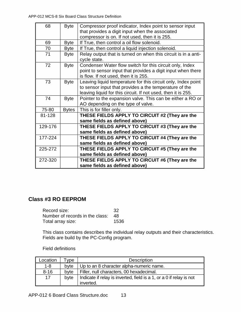
47-48 Word Check sum of the check sum class, not meaningful
Class #23 CHILLER RAM
Record size: 186Number of records in the class: 1Total array size: 186
This class contains information that is dynamically updated during running.Information dealing with the status of the chiller and circuits are stored in this class.
Field definitions for Heatcraft configuration file:
Location Type Description1 Byte Current chiller capacity control state, index pointer into an
array of capacity control state names. See below fordefinition of this array.
2 Byte Number of capacity steps wanted on. A number from 0 to16.
3-6 Ulong Time recorded in seconds that the system has been in thecurrent chiller control state.
7-8 INT Sensitivity timer that is incremented by an amount that isdeveloped based upon the actual and target temperatureand the slope of the actual temperature. When this valueis greater than the step delay set point, a capacity step iseither added or subtracted.
9-19 THESE FIELDS APPLY TO CIRCUIT #1 (THEY WILLBE REPEATED FOR CIRCUITS 2, 3, 4, 5 & 6)
9 Byte Current circuit control state, index pointer into an array ofcircuit control state names. See below for definition of thisarray.
10 Byte Number of capacity steps on this circuit that are turnedon. A number from 0 to 4.
11-14 Ulong Time recorded in seconds that the system has been in thecurrent circuit control state.
15-16 INT Oil differential, calculated difference between oil andsuction pressure.
17-18 INT Variable step capacity wanted on for this circuit. This isused for holding the percentage of opening of a screwcompressor.
19 Byte Used to determine if an individual circuit is disabled. Thisis needed with the pump control logic.
20-30 THESE FIELDS APPLY TO CIRCUIT #231-41 THESE FIELDS APPLY TO CIRCUIT #3

APP-012 MCS-8 Six Board Class Structure Definition
APP-012 6 Board Class Structure.doc 26
42-52 THESE FIELDS APPLY TO CIRCUIT #453-63 THESE FIELDS APPLY TO CIRCUIT #664-74 THESE FIELDS APPLY TO CIRCUIT #675-78 Long Calculate slope of the control temperature. Difference
between the current value and the temperature valuebased upon the slope interval time. This value is used todetermine if the number of steps of capacity should bechanged.
79-82 Long Previous calculate slope of the control temperature.83-84 INT Calculate the average control temperature. Not used at
this time.85-86 INT Hold the previous calculated average control
temperature. Not used at this time.87-88 INT Variable step capacity wanted on for the entire system.
89 Byte Number of capacity steps wanted on. A number from 0 to16, will be equal to or one less than the number of stepswanted on.
90-91 INT Variable step capacity actually turned on for the entiresystem.
92 Byte Indicates the lead circuit (compressor). A number from 1to 6.
93-94 INT Condenser control slope for circuit #1.95-96 INT Condenser control slope for circuit #2.97-98 INT Condenser control slope for circuit #3.99-100 INT Condenser control slope for circuit #4.
101-102 INT Condenser control slope for circuit #5.103-104 INT Condenser control slope for circuit #6.105-106 INT Current amps that the chiller is drawing.107-108 INT Current kw that the chiller is drawing.109-121 THESE FIELDS APPLY TO CIRCUIT #1 (THEY WILL
BE REPEATED FOR CIRCUITS 2, 3, 4, 5 & 6) theycontain information on the expansion valve.
109 Byte Valve control state .110-113 ulong State timer.114-115 INT Percentage of valve opening.116-117 INT Saturated suction temperature.118-119 INT Calculated super heat.120-121 INT Adjusted time between recalculating the needed
percentage of opening of the valve.122-134 THESE FIELDS APPLY TO CIRCUIT #2135-147 THESE FIELDS APPLY TO CIRCUIT #3148-160 THESE FIELDS APPLY TO CIRCUIT #4161-173 THESE FIELDS APPLY TO CIRCUIT #6174-186 THESE FIELDS APPLY TO CIRCUIT #6
APP-012 MCS-8 Six Board Class Structure Definition
APP-012 6 Board Class Structure.doc 27
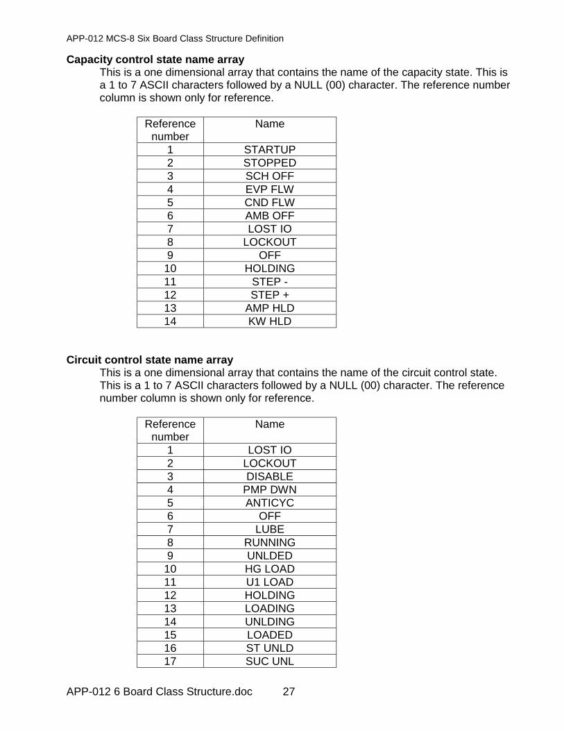
Capacity control state name arrayThis is a one dimensional array that contains the name of the capacity state. This isa 1 to 7 ASCII characters followed by a NULL (00) character. The reference numbercolumn is shown only for reference.
Referencenumber
Name
1 STARTUP2 STOPPED3 SCH OFF4 EVP FLW5 CND FLW6 AMB OFF7 LOST IO8 LOCKOUT9 OFF
10 HOLDING11 STEP -12 STEP +13 AMP HLD14 KW HLD
Circuit control state name arrayThis is a one dimensional array that contains the name of the circuit control state.This is a 1 to 7 ASCII characters followed by a NULL (00) character. The referencenumber column is shown only for reference.
Referencenumber
Name
1 LOST IO2 LOCKOUT3 DISABLE4 PMP DWN5 ANTICYC6 OFF7 LUBE8 RUNNING9 UNLDED
10 HG LOAD11 U1 LOAD12 HOLDING13 LOADING14 UNLDING15 LOADED16 ST UNLD17 SUC UNL

APP-012 MCS-8 Six Board Class Structure Definition
APP-012 6 Board Class Structure.doc 28
18 SUC HLD19 DIS UNL20 DIS HLD21 SAFETY22 TMP UNL23 TMP HLD
Valve control state name arrayThis is a one dimensional array that contains the name of the valve control state.This is a 1 to 7 ASCII characters followed by a NULL (00) character. The referencenumber column is shown only for reference.
Referencenumber
Name
1 LOCKOUT2 CLOSED3 PREPUMP4 STARTUP5 SPR CTL6 LOW SPR7 LOW PSI
Class #24 RO RAM STATUS
Record size: 4Number of records in the class: 48Total array size: 192
This class contains information that is dynamically updated during running.Information dealing with the status of the relay outputs is stored in this class.
Field definitions
Location Type Description1 Byte Current status of the relay output:
• 0 = on,• 1= off.
2 Byte Not used at this time.

APP-012 MCS-8 Six Board Class Structure Definition
APP-012 6 Board Class Structure.doc 29
3 Byte Current control status of the relay output:• 0 = AUTO, let the system determine on or off.• 1= MANON, force the relay output to on.• 2 = MANOFF, force the relay output to off.• 3 = LOCKON, the system has locked the relay
output on.• 4 = LOCKOFF, the system has locked the relay
output off.4 Byte If the relay output is to be pulsed, count of the maximum
pulses to be on. Each count is 1/10 of a second on. Ifcontrol algorithm time is 6 seconds then the value wouldbe 60. If not used set to 0.
Class #25 RO RAM INFO
Record size: 28Number of records in the class: 48Total array size: 1344
This class contains information that is dynamically updated during running.Information dealing with the run time and cycling of the relay outputs is stored in thisclass.
Field definitions
Location Type Description1 Byte Last state of the relay output.2 Byte Not used at this time.
3-5 HHMMSS
Time that the relay output was lasted turned on.
6-8 HHMMSS
Time that the relay output was lasted turned off.
9-12 Ulong Run time of the relay output today. This cleared at midnight.
13-14 Word Number of cycles today. This cleared at mid night.15-18 Ulong Run time of the relay output yesterday.19-20 Word Number of cycles yesterday.21-24 Ulong Total run time of the relay output since the last clear point
function was executed.25-28 Ulong Total number of cycles since the last clear point function
was executed..

APP-012 MCS-8 Six Board Class Structure Definition
APP-012 6 Board Class Structure.doc 30
Class #26 AO RAM STATUS
Record size: 6Number of records in the class: 12Total array size: 72
This class contains information that is dynamically updated during running.Information dealing with the status of the analog outputs is stored in this class.
Field definitions
Location Type Description1-2 INT Current setting of the analog output as a percentage.
Number from 0 to 1000, allow for 1 decimal place..3 Byte Not used at this time.4 Byte Control state:
• 0 = AUTO, system will determine percent ofopening.
• 1 = MANUAL, the analog output will be set tothe value that is stored in the manual valuefield.
5-6 INT Manual value, this will be used when the analog output isin manual. A number from 0 to 1000, allow for 1 decimalplace.
Class #27 AO RAM INFO
Record size: 20Number of records in the class: 12Total array size: 240
This class contains information that is dynamically updated during running.Information dealing with percentage of the valve opening is stored in this class.
Field definitions
Location Type Description1-2 INT Last state of the analog output.3-4 INT Today’s maximum percentage open.5-6 INT Today’s minimum percentage open.
7-10 Long Today’s average percentage open.11-14 Long Not used at this time.15-16 INT Yesterday’s maximum percentage open.17-18 INT Yesterday’s minimum percentage open.19-20 INT Yesterday’s average percentage open.

APP-012 MCS-8 Six Board Class Structure Definition
APP-012 6 Board Class Structure.doc 31
Class #28 SI RAM STATUS
Record size: 2Number of records in the class: 48Total array size: 96
This class contains information that is dynamically updated during running.Information dealing with the status of the sensor inputs both analog and digital arestored in this class.
Field definitions
Location Type DescriptionAnalog input sensor
1-2 INT Current value of the sensor. Note, all decimal places areassumed.
Digital input sensor1 Byte Current status of the digital input:
• 0 = on,• 1= off.
2 Byte Not used
Class #29 SI RAM INFO
Record size: 28Number of records in the class: 48Total array size: 1344
This class contains information that is dynamically updated during running.Information dealing with the sensor readings of an analog sensor or the run timeand cycling of a digital sensor input are stored in this class.
Field definitions for an analog sensor
Location Type Description1-2 INT Previous value of the sensor. Note, all decimal places are
assumed.3-4 INT Today’s maximum sensor reading.5-6 INT Today’s minimum sensor reading.
7-10 Long Today’s average sensor reading.11-14 Long Not used at this time.

APP-012 MCS-8 Six Board Class Structure Definition
APP-012 6 Board Class Structure.doc 32
15-16 INT Yesterday’s maximum sensor reading.17-18 INT Yesterday’s minimum sensor reading.19-20 INT Yesterday’s average sensor reading.
Field definitions for digital sensor input
Location Type Description1 Byte Last state of the digital sensor input.2 Byte Not used at this time.
3-5 HHMMSS
Time that the digital sensor input was lasted turned on.
6-8 HHMMSS
Time that the digital sensor input was lasted turned off.
9-12 Ulong Run time of the digital sensor input today, stored inseconds. This cleared at mid night.
13-14 Word Number of cycles today. This cleared at mid night.15-18 Ulong Run time of the digital sensor input yesterday, stored in
seconds.19-20 Word Number of cycles yesterday.21-24 Ulong Total run time of the digital sensor input since the last
clear point function was executed.25-28 Ulong Total number of cycles since the last clear point function
was executed..
Class #30 MCSIO RAM
Record size: 50Number of records in the class: 1Total array size: 50
This class contains information that is dynamically updated during running.Information dealing with the status and message counts of the MCS-IOS are storedin this class.
Field definitions
Location Type Description1-2 Word Continuous count of all valid messages.3-4 Word Continuous count of all invalid messages.5-6 Word Continuous count of all messages.7-8 Word Not used at this time.
9-10 Word Not used at this time.

APP-012 MCS-8 Six Board Class Structure Definition
APP-012 6 Board Class Structure.doc 33
11 Byte Dynamic count of consecutive no response from MCS-IO#1. Used to determine if MCS-IO should be marked offline.
12 Byte Dynamic count of consecutive no response from MCS-IO#2. Used to determine if MCS-IO should be marked offline.
13 Byte Dynamic count of consecutive no response from MCS-IO#3. Used to determine if MCS-IO should be marked offline.
14 Byte Dynamic count of consecutive no response from MCS-IO#4. Used to determine if MCS-IO should be marked offline.
15 Byte Dynamic count of consecutive no response from MCS-IO#5. Used to determine if MCS-IO should be marked offline.
15-16 Word Dynamic count of consecutive valid responses from MCS-IO #1. Used to determine if off line MCS-IO should bemarked on line.
17-18 Word Dynamic count of consecutive valid responses from MCS-IO #2. Used to determine if off line MCS-IO should bemarked on line.
19-20 Word Dynamic count of consecutive valid responses from MCS-IO #3. Used to determine if off line MCS-IO should bemarked on line.
21-22 Word Dynamic count of consecutive valid responses from MCS-IO #4. Used to determine if off line MCS-IO should bemarked on line.
23-24 Word Dynamic count of consecutive valid responses from MCS-IO #5. Used to determine if off line MCS-IO should bemarked on line.
25-26 Word Count of the number of times that MCS-IO #1 has beenmarked off line.
27-28 Word Count of the number of times that MCS-IO #2 has beenmarked off line.
29-30 Word Count of the number of times that MCS-IO #3 has beenmarked off line.
31-32 Word Count of the number of times that MCS-IO #4 has beenmarked off line.
33-34 Word Count of the number of times that MCS-IO #5 has beenmarked off line.
35-36 Word Status of MCS-IO #1.• 0 = off line• 1 = on line• 2 = not used

APP-012 MCS-8 Six Board Class Structure Definition
APP-012 6 Board Class Structure.doc 34
37-38 Word Status of MCS-IO #2.• 0 = off line• 1 = on line• 2 = not used
39-40 Word Status of MCS-IO #3.• 0 = off line• 1 = on line• 2 = not used
41-42 Word Status of MCS-IO #4.• 0 = off line• 1 = on line• 2 = not used
43-44 Word Status of MCS-IO #5.• 0 = off line• 1 = on line• 2 = not used
45-47 HHMMSS
Last time that MCS-IO #1 was marked as off line.
48-50 HHMMSS
Last time that MCS-IO #2 was marked as off line.
51-53 HHMMSS
Last time that MCS-IO #3 was marked as off line.
54-56 HHMMSS
Last time that MCS-IO #4 was marked as off line.
57-59 HHMMSS
Last time that MCS-IO #5 was marked as off line.
Class #31 SW STATUS
Record size: 18Number of records in the class: 1Total array size: 18
This class contains information that is dynamically updated during running.This class contains information as to the status of the configuration file and thesoftware version number.
Field definitions
Location Type Description1 Byte Status of the configuration file:
• 1 (true) = valid config• 0 (false) = invalid config

APP-012 MCS-8 Six Board Class Structure Definition
APP-012 6 Board Class Structure.doc 35
2 Byte Is a down line load of the config taking place:• 1 (true) = yes• 0 (false) = no
3 Byte Not used at this time.4-5 Word Not used at this time.
6-18 Char Software version number, obtained from EEPROM.
Class #32 SPARE
This class has not been assigned at this time.
Class #33 ALARM HISTORY
Record size: 16Number of records in the class: 60Total array size: 960
This class contains information relating to alarm that is dynamically updated whenan alarm is generated. This is a wrap around structure, the index that is required tolocate the most current alarm is stored in the HISTORY_INDEX_RAM. Class #38.The latest 60 alarms are keep, once 60 alarms have been stored, the next alarm willforce the oldest to be dropped.
There are 3 types of alarms:• System alarms, these alarms are relate to a system error condition
occurring, e.g. POWER RETURNED or notification of action, e.g.ROTATED LEAD #1.
• Set point alarms, these are alarms have occurred because the conditionthat the set point is monitoring has exceeded the time in the set point.E.g. HI DISCH PSI.
• Sensor alarms, these alarms occur when a sensor has been shorted or isopen. The sensor reading is no longer valid.

APP-012 MCS-8 Six Board Class Structure Definition
APP-012 6 Board Class Structure.doc 36
Field definitions
Location Type Description1 Byte Number that indicates the circuit, sensor number, MCS-
IO# or not used. This will be displayed with the alarm forcertain types that require additional information.
2 Byte • Index if less than 60, index into an array of alarmnames. These alarms are system alarms. Refer toSystem Alarm array definition below.
• Index if greater or equal to 60 but less than 120, indexinto the set point array to get the alarm name. Thesealarms have been generated based upon a set point.
• Index if greater than 120, index into the sensor array toget the sensor name that has failed.
3 Byte Hour that the alarm occurred. This is military time.4 Byte Minute that the alarm occurred.5 Byte Second that the alarm occurred.6 Byte Month that the alarm occurred.7 Byte Day of the month that the alarm occurred.8 Byte Day of the week that the alarm occurred.
9-14 Byte Not used at this time.15-16 INT Not used at this time.
System Alarm name arrayThis is a one-dimensional array that contains the name of the system alarm. This isa 1 to 16 ASCII characters followed by a NULL (00) character. The referencenumber column is shown only for reference.
Referencenumber
Name
1 POWER FAILED2 COMPUTER RESET3 BATTERY FAILED4 LCD FAILURE5 HW DATE INVALID6 HW TIME INVALID7 SW DATE INVALID8 SW TIME INVALID9 ALARMS CLEARED
10 POWER RETURNED11 RAM INTEGRITY12 STPT CHANGED13 RO MANUAL14 AO MANUAL15 SI MANUAL16 POINT INFO CLEAR

APP-012 MCS-8 Six Board Class Structure Definition
APP-012 6 Board Class Structure.doc 37
17 CLOCK SET18 CFG DOWNLOADED19 ROTATED LEAD\020 METER CLEARED21 INVLD ALGO STATE22 INVLD RO MAN23 INVLD CFG FLAG24 CPURAM INTEGRITY25 INVLD AO MAN26 DAYLIGHT SAVINGS27 (spaces, not used)28 (spaces, not used)29 MCS-RO8 #1 LOST30 MCS-RO8 #2 LOST31 MCS-RO8 #3 LOST32 INVALID CONFIG33 INVALID CFG VER34 MCS-I/O #1 LOST35 MCS-I/O #2 LOST36 MCS-I/O #3 LOST37 WATCHDOG RESET38 SENSOR FAULT39 EMERGENCY STOP40 SMOKE ALARM LOCK41 NO AIR FLOW LOCK42 COMP1 PROOF LOCK43 AMBIENT SENSOR44 PHASE LOSS45 MOTOR OIL SENSOR46 DISCHARGE SENSOR47 SUCTION SENSOR48 COMP OIL SENSOR49 MOTOR TMP SENSOR50 MOTOR RPM SENSOR51 LOST IO SHUTDOWN52 HEAT PROOF FAULT53 INVALID CFG TYPE54 PWR FAIL LOCKOUT55 LOST I/O RESTART56 COMP2 PROOF LOCK57 LOW SUPERHT58 HI DUCT STATIC59 MCS-SI8 #1 LOST60 MCS-SI8 #2 LOST61 MCS-SI8 #3 LOST

APP-012 MCS-8 Six Board Class Structure Definition
APP-012 6 Board Class Structure.doc 38
Class #34 MACHINE RAM
Record size: 16Number of records in the class: 1Total array size: 16
This class contains information that the system uses to keep track of the MCS-IOthat is being acessed. It also tracks the number of power failures that the systemhas encountered. This information is only useful to the control algorithm.
Field definitions
Location Type Description1-4 Byte Not used at this time.5 Byte Continuous counting of the number of power failures.
6-14 Byte Not used at this time.15 Byte Address, 0 through 5, of the current MCS-IO that is being
accessed.16 Byte Hardware version number
Class #35 RTC RAM
Record size: 46Number of records in the class: 1Total array size: 46
This class contains real time clock information. It is updated by reading the real timeclock settings into this class upon power up. If the real time clock contains validdata, it is then moved into the SW TIME RAM class, software clock. If the data isnot valid, then the data that had been stored in the SW TIME RAM class is loadedinto this class and the real time clock. This class is referenced whenever the time ordate information is needed.
Field definitions
Location Type Description1-32 Byte Not used at this time.33 Byte Current second.34 Byte Current minute.35 Byte Current hours.36 Byte Current day of the week.37 Byte Current day of the month.38 Byte Current month.39 Byte Current year.
40-46 Byte Not used at this time.

APP-012 MCS-8 Six Board Class Structure Definition
APP-012 6 Board Class Structure.doc 39
Class #36 SW TIME RAM
Record size: 12Number of records in the class: 1Total array size: 12
This class is reserved for use by the MCS control algorithm.
The software clock is maintained in this class.
Field definitions
Location Type Description1 Byte 10 milla-second timer.2 Byte 100 milla-second timer.3 Byte Current second ticker.4 Byte Current minute ticker.5 Byte Current hours ticker.6 Byte Old second ticker.7 Byte Not used at this time8 Byte Current day of the week.9 Byte Current day of the month.
10 Byte Current month.11 Byte Current year.12 Byte Current year.
Class #37 SPARE
This class has not been assigned at this time.
Class #38 HISTORY POINTERS
Record size: 12Number of records in the class: 1Total array size: 12
This class dynamically keeps track of where the current sample is to be stored inthe HISTORY RAM class and where the next alarm will be stored in ALARMHISTORY class. This class is used in conjunction with the HISTORY RAM class todisplay history and with the ALARM HISTORY class to display the alarms.

APP-012 MCS-8 Six Board Class Structure Definition
APP-012 6 Board Class Structure.doc 40
Field definitions
Location Type Description1 Byte Not used at this time.2 Byte Filler, not used. Places word on the proper boundary.
3-4 Word Not used at this time.5-6 Word Relative index to the first history sample. This is used to
determine when the samples have filled the structure thatholds the samples. Oldest sample will be replaced.
7-8 Word Relative index to the last, most recent, history sample.This index is stepped after each sample is added.
9-10 Word Not used at this time.11 Byte Relative index to the first alarm. This is used to determine
when the alarm have filled the structure that holds thealarm. Oldest alarm will be replaced.
12 Byte Relative index to the last, most recent, alarm. This indexis stepped after each alarm is added.
Class #39 HISTORY RAM
Record size: 112Number of records in the class: 144Total array size:
This class contains the actual history sample. Status of all points and states arecaptured. This is dynamically updated at the sample time interval.
Field definitions
Location Type Description1-3 HHM
MSSThe time of this sample.
4 Byte Index that points to the control state of the system.5 Byte Relay output settings for the 8 ROS on MCS-8.6 Byte Relay output settings for the 8 ROS on MCS-I/O #1.7 Byte Relay output settings for the 8 ROS on MCS-I/O #2.8 Byte Relay output settings for the 8 ROS on MCS-I/O #3.9 Byte Relay output settings for the 8 ROS on MCS-I/O #4.
10 Byte Relay output settings for the 8 ROS on MCS-I/O #5.11-34 INT Analog output percentage opening for AO #1 through AO
#12.

APP-012 MCS-8 Six Board Class Structure Definition
APP-012 6 Board Class Structure.doc 41
34-130 INT Sensor input #1 analog value. The type of input eitherdigital or analog and if analog, type of sensor must bedetermined from the SI class. This is repeated for SI’s 2through 48.
131-134 Long Calculate control slope.135 Byte Number of capacity steps that the system wants on.136 Byte Number of capacity steps that the system has turned on.
137-138 INT If variable capacity, this is the percentage wanted.139-144 FOLLOWING INFORMATION IS FOR CIRCUIT #1.
139 Byte Control state for circuit #1.140 Byte Number of steps turned on in circuit #1. Number from 0 to
4.141-142 INT Calculated oil differential if it exists for circuit #1.143-144 INT If variable capacity, this is the percentage wanted for
circuit #1.145-150 ABOVE INFORMATION REPEATED FOR CIRCUIT #2.151-156 ABOVE INFORMATION REPEATED FOR CIRCUIT #3.157-162 ABOVE INFORMATION REPEATED FOR CIRCUIT #4.163-168 ABOVE INFORMATION REPEATED FOR CIRCUIT #5.169-174 ABOVE INFORMATION REPEATED FOR CIRCUIT #6.
Class #40 RAM BEG MARK
Record size: 9Number of records in the class: 1Total array size: 9
This class contains a static marker, ‘RAM BEGIN’.
Class #41 RAM CFG MARK
Record size: 7Number of records in the class: 1Total array size: 7
This class contains a static marker, ‘RAM CFG.
Class #42 RAM END MARK

APP-012 MCS-8 Six Board Class Structure Definition
APP-012 6 Board Class Structure.doc 42
Record size: 7Number of records in the class: 1Total array size: 7
This class contains a static marker, ‘RAM END.
Class #43 RAM AD RAW
Record size: 2Number of records in the class: 8x10Total array size: 160
This class contains raw analog to digital, AD, counts. The class is structured to hold10 individual scans or AD counts from 8 input channels. From these counts aweighted average or filtered counts are developed, refer to Class #45. Thisinformation is build by each MCS board, both the MCS-8 and the MCS-IO boards.
Field definitions
Location Type Description1-2 Word Raw AD count for first scan for the first channel
3-20 Word Raw AD count for the first channel, scans 2 through 10.21-160 Above information is repeated 7 times for channels 2
through 8.
Class #44 SPARE
This class has not been assigned at this time.
Class #45 RAM ALGO FILTERED
Record size: 2Number of records in the class: 8 if MCS-IOTotal array size: 16 if MCS-IONumber of records in the class: 48 if MCS-8Total array size: 96 if MCS-8

APP-012 MCS-8 Six Board Class Structure Definition
APP-012 6 Board Class Structure.doc 43
This class contains the filtered AD count for each channel. The MCS-IO’s developthis class and then transmit it to the MCS-8 when requested. The MCS-8 will holdall of the filtered AD counts, maximum of 48, and then convert the counts intomeaningful information based upon the sensor type associated with each channel.
Field definitions
Location Type Description1-2 Word Filtered AD count for sensor input #1 based upon the 10
raw AD counts. The filtered AD count is developed everysecond.
3-96 Repeated for sensors #2 through #48.
Class #46 RAM OUTPUT IMAGE
Record size: 14Number of records in the class: 6Total array size: 84
This class contains information as to the relay and analog output status for eachMCS board. The first record is for the MCS-8 and records 2 through 6 are for MCS-IO #1 through #5. The information is build by the MCS-8 and then transmitted toeach MCS-IO for it to take the appropriate action. Turning on or off relay outputs,pulsing relay outputs and pulsing analog output.
Field definitions
Location Type Description1-2 Word Relay output status in bit format. If on, bit = 0 else bit =1.
Counting the bits from right to left to and beginning with 0,bit 0 will have the status of the first RO. Bit 1 will have thesecond RO status and so on. Bits 8 through 16 are notused and are filled with 0.
3-4 Word This is the number of counts that the AO #1 should beheld on. This is updated every second.
5-6 Word Repeated for AO #2.7 Byte If the relay output #1 is to be pulsed, this is the number of
counts that the RO should be held on. This is updatedevery second.
8-14 Byte Repeat of previous field for relay outputs 2 through 8.
Class #47 RS232 RAM

APP-012 MCS-8 Six Board Class Structure Definition
APP-012 6 Board Class Structure.doc 44
Record size: 10Number of records in the class: 1Total array size: 10
This class contains information that is dynamically updated during running.Information dealing with the status and message counts of the RS232 port arestored in this class.
Field definitions
Location Type Description1-2 Word Count of the valid messages that have been received over
the RS232 port.3-4 Word Count of the invalid messages that have been received
over the RS232 port.4-6 Word Not used at this time.7-8 Word Count of the valid messages that have been transmitted
over the RS232 port.9 Byte Not used at this time.
10 Byte Not used at this time.
Class #48 RS485 RAM
Record size: 10Number of records in the class: 1Total array size: 10
This class contains information that is dynamically updated during running.Information dealing with the status and message counts of the RS485 port arestored in this class.
Field definitions
Location Type Description1-2 Word Count of the valid messages that have been received over
the RS485 port.3-4 Word Count of the invalid messages that have been received
over the RS485 port.4-6 Word Not used at this time.7-8 Word Count of the valid messages that have been transmitted
over the RS485 port.9 Byte Not used at this time.
10 Byte Not used at this time.

APP-012 MCS-8 Six Board Class Structure Definition
APP-012 6 Board Class Structure.doc 45
Class #49 SETPOINT RAM
Record size: 2Number of records in the class: 60Total array size: 120
This class contains the current value of the set point.
Field definitions
Location Type Description1-2 INT Value of the set point. Decimal places are assumed.
Class #50 METER RAM
Record size: 86Number of records in the class: 1Total array size: 86
This class is only used in the HOME algorithm code.
Class #51 METER HISTORY
Record size: 468Number of records in the class: 1Total array size: 468
This class is only used in the HOME algorithm code.
Class #52 RESERVED
Class #53 RO RAM EXTRA
Record size: 1Number of records in the class: 48

APP-012 MCS-8 Six Board Class Structure Definition
APP-012 6 Board Class Structure.doc 46
Total array size: 48
This class dynamically updated and it contains information for pulsed relay outputs.
Field definitions
Location Type Description1 Byte For pulsed relay outputs, this will be the manual
percentage of opening. Value will only be used when therelay is placed in manual. This value can be updated in arunning unit.
Class #54 LOCKOUT HISTORY RAM
** not available with the six board algorithm **
Record size: 8Number of records in the class: 31Total array size: 248
This class contains information that relates to the circuit that caused the lockout.This structure is similar to the alarm history structure class #33. It is accessed in thesame matter.
Field definitions
Location Type Description1 Int Suction PSI of circuit that has caused lock out.2 Int Discharge PSI of circuit that has caused lock out.3 Int Oil differential PSI of circuit that has caused lock out.4 Int Amps of circuit that has caused lock out.5 Int Suction temperature of circuit that has caused lock out.6 Int Discharge temperature of circuit that has caused lock out.7 Int Oil temperature of circuit that has caused lock out.8 Int Motor temperature of circuit that has caused lock out.