Embed Size (px)
Citation preview
This Guidance is the property of Department of Energy and Climate Change (DECC), 3 Whitehall Place,
London,SW1A 2HH.
© DECC 2013
MCS
MCS Domestic RHI Metering Guidance v1.1

2
Contents
1. DEFINITIONS 5
2. INTRODUCTION 6
3. SCOPE 6
4. CONTRACTS AND CUSTOMER REQUIREMENTS 7
4.1 Sub-contracting 8
5. METER-READY 9
6. METERING FOR PAYMENT 12
6.1 Metering concept for heat pumps and biomass boilers or stoves with back boilers 13
6.2 Meter details 14
Heat meters 14
Electricity meters (for heat pumps only) 15
Gas meters (if required) 15
Oil meters (if required) 16
6.3 Additional requirements 17
7. METERING AND MONITORING SERVICE PACKAGES 18
7.1 Heat pump MMSPs 22
Heat metering 22
Electricity metering 24
Gas metering 24
Oil metering 25
Temperature measurements 26
7.2 Pellet biomass boiler MMSPs 26
Heat metering 27
Electricity metering 28

3
Gas metering 29
Oil metering 30
Temperature measurements 31
7.3 Viewing platform 31
7.3.1 Requirements for MCS Contractor’s view 31
7.3.2 Customer view of the data 32
Data submission to DECC and to Ofgem 33
REFERENCED PUBLICATIONS 35
ANNEX A: LOCATION OF ISOLATION VALVES FOR COMMON TYPES OF HEAT
PUMPS AND BIOMASS BOILERS 36
ANNEX B: PROCEDURE A- WHEN SHOULD A HEAT PUMP OR BIOMASS BOILER
OR STOVE WITH BACK BOILER BE METERED FOR PAYMENT? 39
ANNEX C: EXAMPLES FOR SECTION 6, METERING FOR PAYMENT 40
Worked Example 1: A pellet biomass boiler providing space heating and domestic hot water in a
second home 40
Worked Example 2: An air-source heat pump with a back-up fossil fuel boiler providing both space
heating and domestic hot water 42
Worked Example 3: A ground-source heat pump with integrated domestic hot water cylinder 45
Worked Example 4: A split-system air-source heat pump providing space heating and domestic hot
water 48
ANNEX D: FUNDAMENTALS OF HEAT METERING AND KEY POINTS TO
CONSIDER 52
ANNEX E: WORKED EXAMPLES OF REQUIREMENTS FOR METERING AND
MONITORING SERVICE PACKAGES 55
Worked Example 1: An air-source heat pump providing space heating and domestic hot water 55
Meter resolution 58

4
Worked Example 2: A ground-source heat pump with integrated domestic hot water cylinder 60
Meter resolution 62
Worked Example 3: A split-system air-source heat pump with back-up fossil fuel boiler and
immersion heating 64
Meter resolution 66
Worked Example 4: A pellet biomass boiler providing space heating and domestic hot water 67
Meter resolution 68
AMENDMENTS ISSUED SINCE PUBLICATION 71

5
1. Definitions
This Microgeneration Installation Metering Guidance makes use of a number of terms when
prescribing certain requirements and procedures. In the context of this document:
The term ‘must’ identifies a requirement by law at the time of publication.
The term ‘shall’ prescribes a requirement or procedure that is intended to be complied
with in full and without deviation.
The term ‘should’ prescribes a requirement or procedure that is intended to be
complied with unless reasonable justification can be given.
The term ‘MCS Contractor’ identifies an individual, body corporate or body
incorporate, applying for or holding MCS certification for delivery of supply, design and / or
design review, installation, set to work, commissioning services and handover for systems
covered by the relevant technology standard.
The term ‘Contract’ prescribes an undertaking for the design, supply, installation, set
to work, commissioning and handover of systems covered by the relevant technology
standard. All contracts must be written to be compliant with MCS requirements.
The term ‘installation’ refers to the activities associated with placement and fixing of a
microgeneration or metering system.
The term ‘Commissioning’ prescribes the advancement of an installation from the
state of setting to work of an installation, the regulation of the system and the fine tuning of
the static completion to full working order to the specified requirements. Commissioning
includes recording all relevant measurements, flow rates and / or test results, and includes
the preparation and submission of a commissioning report or certificate as required by the
relevant technology standard that shall confirm that the system is capable of delivering the
performance quoted to the customer.
The term ‘Handover’ specifies the point in a contract where commissioning and
certification of the system have been satisfactorily completed to the contract specification so
enabling the installation to be formally explained and handed over to the client. Including all
relevant documentation required by the relevant technology standard.
The term ‘Subcontract’ specifies a written contract between an MCS contractor and
another firm for the supply of products and services in connection with the fulfilment of a
contract.

6
2. Introduction
The government is introducing the Renewable Heat Incentive (RHI) to support renewable heat
generation in the domestic sector. The scheme will offer tariff payments for supported
technologies which include MCS (or equivalent) certified solar thermal systems, ground source
heat pumps, air source heat pumps and biomass boilers or stoves with back boilers for use in the
domestic sector.
All RHI installations should be made meter-ready. In addition, in some cases, applicants will
require metering for payment in order for their systems to be RHI compliant, whilst in other cases
applicants could be paid extra for metering and monitoring system performance. This document
sets out the specification of the metering and meter readiness required, and responsibilities that
MCS Contractors shall meet for the installation to be RHI compliant.
Installation of metering in accordance with this document shall only be undertaken by an MCS
Contractor certified for the corresponding RHI technology being metered.
NOTE: For existing installations the MCS Contractor shall take into account the requirements of
the corresponding MCS Installation Standards.
3. Scope
This document is concerned with three types of metering:
Section 5: Meter-ready- All RHI installations should be meter-ready for DECC’s own metering to
be fitted to the site if selected.
Section 6: Metering for payment- Where a heat pump or biomass boiler is installed alongside
certain other heating systems or where the MCS Contractor is advised that the property is a
second home, then the renewable heating system shall be metered in order to receive payment
under the RHI. Procedure A in Annex B provides further guidance for when Metering for
Payment is required. The specifications for the metering and other requirements are detailed in
Section 6.
Section 7: Metering and Monitoring Service Packages- A customer may install an optional
metering and monitoring service package for either a pellet biomass boiler or a heat pump for
which they will receive a financial uplift. The specifications for installation of meters as part of

7
these packages are detailed in this section along with the other requirements in order for the
package to be installed in a form that is compliant with the RHI.
4. Contracts and customer requirements
The normal MCS requirements regarding contracts and customer requirements as in MCS 001
apply here, some of the most pertinent of which are reproduced below:
“A contract for the sale and installation of a system shall be entered into only between an MCS
Contractor and a Customer. An MCS Contractor may carry out work under subcontract to
another MCS Contractor in which case the requirements specified in Section 4.1 must be
satisfied.
“If the MCS certified MCS Contractor obtains sales leads from any third party, the MCS
Contractor must require that the third party complies with all the relevant requirements of the
MCS standards and Consumer Code. The MCS Contractor will be responsible for any non-
compliance.
“The MCS Contractor shall have procedures to handle enquiries, produce quotes and accept
orders/contracts. Where relevant these must comply with the consumer code scheme.
“The MCS Contractor shall review orders, contracts or tenders to ensure that:
The requirements are adequately defined for each installation;
The MCS Contractor has the resource and capability to meet the order/contract
requirements. Where the time scales cannot be met, the MCS Contractor shall detail when the
order/contract will be fulfilled;
Responsibility for planning and building control compliance is clearly identified.
“Records of this activity shall be maintained for all orders/contracts and tenders.
“A process shall also exist for managing amendments to contracts/ orders.”
For Metering and Monitoring Service Packages, it is a requirement that the MCS Contractor has
a contract with a Customer (though aspects of this work, for example with respect to maintaining
the data platform, may be subcontracted by the MCS Contractor as in Section 4.1) that specifies
that:

8
The MCS Contractor shall transmit information recorded as part of the MMSP
automatically to a data platform and shall continue to provide a data platform in line with the
requirements in Section 7, including that data completeness and the data platform should be
maintained at 75 % or higher for all sensors on an annual basis for the duration of the Contract
(except where this is as a result of customer error);
The MCS Contractor shall inform the Customer if any part of the MMSP is to be delivered
by a subcontractor on behalf of the MCS Contractor and of the identity of any subcontractor who
is providing a service as part of an MMSP. The MCS Contractor shall also notify the Customer if
that subcontractor changes;
The MMSP can be assigned by the MCS ContractorMCS Contractor to another MCS
ContractorMCS Contractor if the Customer consents;
The Customer who entered into the MMSP contract may assign the contract to another
owner of the accredited domestic RHI installation on giving notice to the MMSP installer if the
Customer ceases to be the owner of the accredited domestic installation;
The MCS Contractor providing an MMSP must provide to the Customer, on request, all of
the information collected under the MMSP agreement over the 12 month period ending on the
date on which the information is requested as well as any other information relating to the
Customer or the MMSP held by the MCS Contractor providing the MMSP.
4.1 Sub-contracting
Where MCS Contractors want to install an eligible Metering and Monitoring Service Package, it
may be particularly likely that the MCS Contractor partners with a third party to fulfil some of the
requirements in this guidance document. In this case, the normal MCS requirements regarding
sub-contracting as specified in the latest version of MCS 001 [1] are particularly relevant and
shall be complied with. For ease of use, these are replicated here:
“In installations for private customers, any work within the scope of the scheme [where “scheme”
is here taken to refer to the context of this guidance document] not undertaken by employees of
the MCS Contractor shall be managed through a formal subcontract agreement between the two
parties in accordance with the policies and procedures employed by the MCS Contractor. These
procedures shall ensure that the subcontractor undertakes the work in accordance with the
requirements of this standard.
“In other situations (for example new build, or for commercial customers), it is permissible for the
physical installation, setting to work and commissioning to be undertaken by others (i.e. not sub-
9
contracted to the MCS Contractor) provided that:
“A contract between the MCS Contractor and the commercial client details obligations on
the client to include that evidence of skills and training of those employed by the client to do
elements of work not undertaken by the MCS Contractor are to be made available to the MCS
Contractor to ensure that the competence requirements of this standard are met and that access
to the site for training and supervision in accordance with the following sections is agreed in
advance.
“The MCS Contractor provides additional product-specific training for those undertaking
the work not undertaken by the MCS Contractor.
“The MCS Contractor assesses a sample number of installations under the contract which
is not less than the square root of the number of installations rounded up to the nearest whole
number (e.g. a new build site of 50 installations then a minimum of 8 are assessed).
“The MCS Contractor assumes responsibility at handover that the installation is in full
compliance with the standard.”
5. Meter-ready
Some installations incentivised through the RHI will have DECC’s own metering fitted where the
metering data may then be used to allow DECC to evaluate the effectiveness of the policy. The
data may be shared with MCS.
DECC intends to install meters to monitor the heat output from a renewable heating system, the
energy consumed by those same heat sources, and the heat output from any back-up fossil fuel
systems. This could require engineers, appointed by DECC, to install a number of heat meters,
electricity meters or other energy meters, depending on the specific heating system and manner
of installation. In addition, DECC will install a number of temperature sensors to develop an
understanding of the behaviour of a range of heating systems, for example temperature
measurement of space heating flow and domestic hot water flow. The sensor outputs will be
connected to a logger that will store all readings and regularly transmit them to a centralized
secure data centre.

10
Where a manufacturer has integrated metering into their product that is compliant with the
metering specified in Section 6 or Section 7, then points 1-3 below will be deemed to have been
met.
All RHI-compliant renewable heating installations should be made meter-ready. MCS Contractors
should:
1. Leave sufficient space for appropriate meters to be fitted in defined locations;
a) Heat pumps and biomass boilers
Annex A shows a flow chart to explain how MCS Contractors can decide on the number of
meters required for some of the commonest types of biomass and heat pump renewable
systems.
The flow meter and return temperature sensor of the heat meter(s) take up the most space and
need to be situated on the return pipework between the circulation pump and the distribution
system. The required length of straight pipework between isolation valves is 20 times the pipe
diameter to enable DECC’s chosen metering to be installed on the return pipework. Table 1
below shows the length of straight pipe required for a number of standard pipe sizes.
Pipe
diameter
(mm)
Total length of straight
pipework required in
return pipe (mm)
Total length of straight
pipework required in the
flow pipe (mm)
15 300 175
22 440 175
28 560 175
35 700 175
42 840 175
Table 1: Meter ready space requirements for different pipe diameters
For each location where a heat meter is required, a section of pipe of 175 mm should be left for
the heat meter temperature sensor in the flow pipework. This should be no more than 2 m from
the flow meter.
b) Solar Thermal
For solar thermal systems, DECC intends to install its own metering on a sample of systems to
measure the heat supplied from the solar thermal panel to the domestic hot water cylinder, heat
drawn from the domestic hot water cylinder and any energy input from other sources to the
domestic hot water cylinder. Therefore an MCS Contractor should leave space in the flow and

11
return pipes for each required heat meter in accordance with Table 1, specifically leaving space
for the flow meter component of each heat meter on:
the return to the solar thermal panel from the domestic hot water cylinder;
the output from any other source that supplies the cylinder; and
the draw off from the domestic hot water cylinder.
(Electricity supplied to immersion heating will be metered separately and there are no space
requirements for such metering.)
2. Install low pressure-drop isolation valves to avoid the need to drain systems when
fitting heat meters;
These should be installed at each point where heat metering is required. The flowchart in Annex
A shows how an MCS Contractor shall identify where to locate isolation valves for the most
common examples of heat pumps and biomass boilers or stoves with back boilers. Heat
metering installed between the isolation valves should be able to record the total heat output from
the heating system (excluding individual room heaters and immersion heating, the latter of which
will be monitored through electricity sensors). Therefore, if there are several return pipes
connected to a renewable heating installation, then each one will need to be heat metered, and
each one will need to be fitted with isolation valves with sufficient separation to allow heat meters
to be installed.
For solar thermal installations, isolation valves do not need to be installed but space must be left
for the meters as specified in point 1b above.
3. Leave sufficient pipework accessible, i.e. not boxed in or under floor boards, to
enable meters to be fitted;
4. Feedback information about the installation
DECC will need to know a number of factors about a site so an application will not be considered
to be “meter-ready” if such information has not been provided. The information shall include the
following:
To be fed back to MCS through the Compliance Certificates:
a. Whether it has been possible to make a system meter-ready in accordance with the
above requirements and, if not, the reason why;
To be reported to the Customer as part of the document pack (so that the Customer can respond
to DECC questions at a later date):

12
b. Whether the thermal transfer fluid in any metering location is composed of water or a
water/inhibiter/antifreeze mixture and what are the components of the mixture concerned;
c. Whether the site uses a defrost mechanism that draws heat from the home;
d. Whether the heat pump or biomass boiler provides hot water and whether this is also
heated with an immersion heater, solar thermal or other system;
e. Whether the RHI installation is a stove with a back boiler;
f. Whether the heat pump or biomass boiler has a single-phase or three-phase connection.
Notes on making an installation ‘meter ready’
Heat meters that have been used by DECC in their metering programmes in the past have
required a mains electricity connection. Therefore, at the same time as installing isolation valves
for the heat meters, MCS Contractors should consider the placement of an easily-accessible
electricity supply to power the heat meters.
6. Metering for Payment
MCS Contractors shall use Procedure A (in Annex B) to determine where metering for payment
is required for biomass and heat pump systems. Note that this procedure shall be followed for all
RHI installations. Where metering for payment is required, MCS Contractors shall install a meter
or meters as follows for the appropriate technologies. Where metering that is already compliant
with this section has been integrated into a manufacturer’s heating product then no additional
metering need be installed.
Metering for payment shall not be required for solar thermal RHI installations. RHI tariff
payments for solar thermal systems will always be based on a deemed quantity as detailed in
RHI Regulations [2].
Table 2 shows the required sensor accuracies for both Metering for Payment and for Metering
and Monitoring Service Packages in Section 7.
Sensor type Accuracy class
Heat meter Class 3 Measuring Instruments Directive (MID) [3]
Electricity meter Class A MID
Gas meter Class 1.5 MID
Oil meter Class 1 MID
Table 2: Sensor accuracies required for different types of energy meter

13
6.1 Metering concept for heat pumps and biomass boilers or stoves with back boilers
6.1.1 For a heat pump, an MCS Contractor shall:
Measure the heat output from a renewable heating system, including compressors, and any non-
renewable energy inputs (for example, electricity or gas) to the components from which heat is
being measured.
For such situations, the renewable heat from the heat pump will be calculated from the
measurements. The number of meters required and complexity of metering vary from one heat
meter and one electricity meter to a combination of heat meters and energy meters. Annex C
provides a number of examples to illustrate the concept. Note that electricity that shall be
metered in accordance with the above requirements shall still be metered even if the electricity
has been generated by a renewable source.
Note on Section 6.1.1:
Where MCS-certified heat pumps are capable of cooling as well as heating and where the
system needs to be metered for payment purposes, the consumer will only be paid their RHI tariff
for the metered heating function of the heat pump.
6.1.2 For a biomass boiler or biomass stove with back-boiler, an MCS Contractor
shall:
Measure the heat output by the thermal transfer fluid from the renewable heating system’s
components as close to the biomass boiler output (flow and return pipes) as possible.
Note that measuring of electricity, gas or oil input is not required for biomass heating systems
where that fuel is being used for ignition purposes. In addition, electricity input to an immersion
heater for a hot water cylinder or integrated electric heaters (where the electric heater is
controlled by the same control system that governs the biomass boiler) also does not need to be
measured. However, some other energy inputs may need to be recorded if it is not possible to
exclude those energy inputs from the heat measurement, for example if it is not possible to
measure only heat output from the biomass boiler part of a combined biomass boiler/oil system.

14
6.2 Meter details
Heat meters
All heat meters used to meter for payment in the domestic RHI shall consist of a flow meter,
matched pair of temperature sensors and a calculator, as well as meet the following
requirements:
Comply with the relevant requirements set out in Annex I to the 2004 Measuring
Instruments Directive (MID);
Comply with the specific requirements listed in Annex MI-004 of the MID;
Fall within accuracy Class 3 or better as defined in Annex MI-004 of the MID;
Be installed according to manufacturer’s instructions.
Where heat metering is to be conducted on an air source heat pump which draws heat from the
home to the evaporator to undertake a defrost process (“reverse flow”), then bi-directional heat
meters are not required. Ofgem will instead make assumptions for heat used for defrost. In this
circumstance, the MCS Contractor shall inform Ofgem that the heat pump operates a reverse
flow defrost mechanism.
Notes on Section 6.2 “Heat meters”:
MCS Contractors are advised to pay careful attention to the following as they can have a significant
impact upon meter readings:
Correct installation of temperature sensors, including appropriate mounting to ensure good
thermal contact with the thermal transfer fluid, appropriate insulation and sensor cables to be run
independently of power cables to limit interference. Sensor cable lengths shall be compliant with
manufacturer’s guidance. Where sensor pockets are used then the manufacturer’s thermal transfer
compound shall be used if specified.
Appropriate selection of heat meters (including consideration of the meter manufacturer’s limit
of operating temperature difference and sizing of the meter to suit heating system’s flow rate and
pressure drop);
Caution when fitting meters on the suction side of pumps. This should only be carried out in a
manner that is compliant with heat meter manufacturer’s instructions;
Wiring of the heat meter calculator unit;
Placement of heat meters so that the meter display is visible to the Customer and easy to
read.

15
It should be possible for meters to be re-calibrated or replaced if necessary without significant
disruption to the heating system.
Annex D outlines the basics of heat metering, including heat meter components and other key issues
to consider.
Electricity meters (for heat pumps only)
All electricity meters used to meter for payment in the domestic RHI shall comply with the
following criteria:
Comply with the relevant requirements set out in Annex I to the 2004 Measuring
Instruments Directive (MID);
Comply with the specific requirements listed in Annex MI-003 of the MID;
Fall within accuracy Class A or better, as defined in Annex MI-003 of the MID;
Be installed by a competent, suitably qualified and registered person in accordance with
industry standards and manufacturers’ instructions, including with respect to safety requirements.
Gas meters (if required)
There are three possible options to metering combined gas and renewable heating systems
(including hybrid systems):
1. If it is possible to meter the heat output from a renewable heating system without
including gas-powered components in that measurement, then the gas input does not need to be
metered.
2. If it is not possible to separately meter the heat output from the renewable heating system
without including gas-powered components in that measurement, then the heat output from the
combined system shall be metered (measurement a), and the heat output from the gas-powered
components shall be metered (measurement b). The renewable system’s heat output can be
determined by Ofgem by subtracting measurement b from measurement a.
3. If it is not possible to conduct the heat metering as in Option 1 or 2, then the gas input
shall be metered in a similar manner to the metering of electricity in the worked examples in
Annex C, and the heat output from the combined gas/renewable heating system shall be
metered. These measurements will be used by Ofgem to calculate the renewable heat
generated by the system.
The preferred approach should be to meter heat only as in Option 1, followed by the approach in
Option 2, and finally Option 3.

16
If metering gas, the gas meter shall comply with the following criteria:
Comply with the relevant requirements set out in Annex I to the 2004 Measuring
Instruments Directive (MID);
Comply with the specific requirements listed in Annex MI-002 of the MID;
Fall within accuracy Class 1.5, or better, as defined in Annex MI-002 of the MID;
Be installed by a competent, suitably qualified and registered person in accordance with
the requirements of the Gas Safety (Installation and Use) Regulations 1998, industry standards
and manufacturers’ instructions, particularly with respect to safety requirements.
Oil meters (if required)
There are three possible options to metering combined oil and renewable heating systems
(including hybrid systems):
1. If it is possible to meter the heat output from a renewable heating system without
including oil-powered components in that measurement, then the oil input does not need to be
metered.
2. If it is not possible to separately meter the heat output from the renewable heating system
without including oil-powered components in that measurement, then the heat output from the
combined system shall be metered (measurement a), and the heat output from the oil-powered
components shall be metered (measurement b). The renewable system’s heat output can be
determined by Ofgem by subtracting measurement b from measurement a.
3. If it is not possible to conduct the heat metering as in Option 1 or 2, then the oil input shall
be metered in a similar manner to the metering of electricity in the worked examples in Annex C,
and the heat output from the combined oil/renewable heating system shall be metered. These
measurements will be used by Ofgem to calculate the renewable heat generated by the system.
The preferred approach should be to meter heat only as in Option 1, followed by the approach in
Option 2, and finally Option 3.
If metering oil, the oil meter in question shall comply with the following criteria:
Comply with the relevant requirements set out in Annex I to the 2004 Measuring
Instruments Directive (MID);
Comply with the specific requirements listed in Annex MI-005 of the MID;
Fall within accuracy Class 1, or better, as defined in Annex MI-005 of the MID;
17
Be installed by a competent, suitably qualified and registered person in accordance with
industry standards and manufacturers’ instructions, including with respect to safety requirements.
Note on Section 6.2:
It is not practical to meter solid fuel energy inputs. For combined non-renewable, solid fuel and
renewable heating systems, such as a renewable heating appliance combined with a stove
burning coal, metering shall only be conducted via the following two options:
1. If it is possible to meter the heat output from a renewable heating system without
including solid fuel-powered components in that measurement, then the solid fuel input does not
need to be metered.
2. If it is not possible to separately meter the heat output from the renewable heating system
without including solid fuel-powered components in that measurement, then the heat output from
the combined system shall be metered (measurement a), and the heat output from the solid fuel-
powered components shall be metered (measurement b). The renewable system’s heat output
can be determined by Ofgem by subtracting measurement b from measurement a.
Option 1 is the preferred approach.
6.3 Additional requirements
An MCS Contractor shall submit required information to Ofgem, as requested. This is to enable
Ofgem to satisfy themselves that the requirements of the RHI regulations are being met and
administer the scheme effectively.
An MCS Contractor shall:
1. label meters clearly for the Customer in a manner that is compliant with Ofgem
requirements;
2. explain to the Customer how to read the meters, including showing the RHI applicant how
the first meter reading is conducted;
3. submit the baseline reading at the time of commissioning to Ofgem and, in addition, MCS
Contractors should verify that the installed meter or meters are functioning properly;
4. select meters that should not need to be re-calibrated during the 7 years of the RHI
payments;

18
5. select heat meters capable of displaying energy in kWh or MWh, gas meters capable of
displaying units of m3 or litres and oil meters capable of displaying units of m3 or litres.
MCS Contractors shall select meters that have been appropriately calibrated for the system in
which the meters are to be installed.
An MCS Contractor shall provide the Customer with a document pack that will include the
process for verifying that the meter is operating, any maintenance requirements, calibration
requirements, meter instructions, information required for meter-readiness by DECC and a
schematic diagram of the installation.
Note on Section 6.3:
Examples of what further information Ofgem is likely to request include the following:
1. Declaration of compliance with MCS Domestic RHI Metering guidance document;
2. Heat use of eligible technology (i.e. space, water heating, room heating (via air, e.g. for
stove), indoor or outdoor swimming pool or combination.
3. Details of fossil fuel inputs to heating system;
4. Information about meters, e.g. number and type of meters and evidence that meters are
MID compliant.
7. Metering and Monitoring Service Packages
Metering and Monitoring Service Packages (MMSPs) consist of energy and temperature meters,
logged on a 2-minute basis, in combination with a data-viewing platform that pulls together the
data and presents it clearly. The aim is to help customers and industry to understand how well
their renewable heating installations are operating and to aid in optimising performance for
customers and in ensuring that the installed renewable heating system operates within the
boundaries and conditions of the design and the product manufacturers’ claims. A number of
example packages are shown in Annex E.
Where an MMSP has been installed which is compliant with the requirements of both Section 6
and Section 7, then this system can be used for metering for payment. In addition, where an
MMSP contains meters that have been integrated into a renewable heating manufacturer’s
equipment then these meters can form part of an MMSP providing that the metering is compliant
with the requirements of both Section 6 and Section 7.

19
The RHI will support MMSPs being installed with heat pumps and pellet biomass boilers, though
not pellet stoves with back boilers. It is noted that no other type of biomass boiler or stove with
back boiler is eligible for MMSPs. This is different to the other metering sections in this
document which pertain to all biomass units incentivised through the RHI.
An RHI applicant will receive an ongoing payment from the start of the MMSP installation until the
end of their RHI tariff payments (maximum period of 7 years) so long as the MMSP continues to
operate and the data platform continues to display data in accordance with RHI regulations [2]
over this period. Where an applicant would normally receive an RHI tariff payment based upon
deemed heat demand then the applicant will continue to receive a tariff based upon deemed heat
demand, but would also receive a top-up payment for installing and maintaining the MMSP.
The information in this section represents minimum requirements for installation of an RHI-
compliant MMSP package. Note that the specifications for the meters in MMSPs are the same
as those for meters in ‘Metering for Payment’ (Section 6) but with higher resolution to account for
the 2-minute data logging interval. This high- frequency metering is important because heat
pumps and biomass boilers have components that can operate at very short intervals and
therefore, in order to capture system performance as completely as is feasible, relatively high
frequency logging is required.
Specifications for measurements for heat pump and pellet biomass boiler MMSPs are shown in
the following tables. With the exception of oil and gas metering which are discussed later in this
document, all measurements shall be recorded but, in some cases (e.g temperature), no
minimum resolution or accuracy has been specified; instead some recommendations are
provided. At other points in the summary tables, recommendations have been provided as
suggestions for best practice.

Heat Pump MMSPs Summary Table
20
Sensor type Minimum resolution Minimum accuracy Example number required
1 Heat metering of heat output from heat pump and heat metering of all additional fossil fuel boilers that are connected to the same heat distribution system
[Resolution of heat meter] ≤ 3 % multiplied by [min. non-zero heat output in 2 minutes]
Class 3 of Measuring Instruments Directive
1 x sensor required for heat pump with 2-pipe output 2 x sensors required for heat pump with 4-pipe or 3-pipe output or bivalent system with 2-pipe heat pump 3 x sensors required for bivalent system with 4-pipe or 3-pipe heat pump (Fewer meters may be used if manufacturer has integrated metering to their unit.)
AND heat meter resolution need not be finer than 1 Wh See Section 7.1 for details
2 Metering of all electrical supplies to heat pump included in heat measurement plus DHW cylinder where this is supplied by heat pump
[Resolution of electricity meter] ≤ 3 % multiplied by [min. non-zero electricity input in 2 minutes]
Class A of Measuring Instruments Directive
1 x sensor where heat pump is incorporated into single unit 2 x sensors where heat pump is composed of two units. + 1 x sensor for immersion heating where DHW is supplied by heat pump
(In addition, we recommend that all integrated electric heaters are metered.)
(We recommend using high resolution meters but electricity meter resolution need not be finer than 1 Wh)
3 Gas metering of inputs to heat pump where required (see 7.1)
10 L or equivalent for other units
Class 1.5 of Measuring Instruments Directive
1 x meter to monitor gas input to heat pump only (if a hybrid system has an integrated gas boiler) if not possible to meter heat output from gas boiler as in Row 1.
4 Oil metering of any oil supplied to heat pump where required (see 7.1)
0.1 litres or equivalent for other units Class 1 of Measuring Instruments Directive
1 x meter to monitor oil input to heat pump (if a hybrid system has integrated gas boiler) only if not possible to meter heat output from oil boiler as in Row 1.
5 Measurement of internal temperature, space heating flow temperature and DHW flow temperature, where this is supplied by the heat pump. (Note that this may need sometimes to be separate to temperature measurements involved in heat metering)
We recommend 0.1 degrees C We recommend Class B for Resistance Temperature Detectors (RTDs) (equivalent accuracy for other types of temperature sensor at typical measurement temperature)
3 x temperatures sensors - includes space heating flow metering, DHW flow metering (where DHW supplied by heat pump), internal temperature
6 For ground-source heat pumps, measurement of ground loop flow and return temperatures.
We recommend 0.1 degrees C We recommend Class B for RTDs (equivalent accuracy for other types of temperature sensor at typical measurement temperature)
2 x temperature sensors for ground loop flow and return
7 For air-source heat pumps only, measurement of external air temperature. This sensor should be suitably sited out of direct sunlight and away from other heat sources
We recommend 0.1 degrees C We recommend Class B for RTDs (equivalent accuracy for other types of temperature sensor at typical measurement temperature)
1 (air source heat pumps only)

21
Sensor type Minimum resolution Minimum accuracy Example number required
1 Heat metering of heat output from biomass boiler and heat metering of any fossil fuel boilers that are connected to the same heat distribution system
[Resolution of heat meter] ≤ 3 % multiplied by [min. non-zero heat output in 2 minutes]
Class 3 of Measuring Instruments Directive
1 x sensor for single biomass system 2 x sensors where overall system contains a fossil fuel boiler in addition to the above.
AND heat meter resolution need not be finer than 1 Wh See Section 7.2 for details
2 Metering of all electrical supplies to biomass boiler included in heat measurement plus DHW cylinder where this is supplied by biomass boiler
[Resolution of electricity meter] ≤ 7.5 % multiplied by [min. non-zero electricity input in 2 minutes]
Class A of Measuring Instruments Directive
1 x sensor for biomass unit + 1 x sensor for immersion heating where appropriate
(In addition, we recommend that all integrated electric heaters are metered.)
(We recommend using high resolution meters but electricity meter resolution need not be finer than 1 Wh)
3 Gas metering of any gas inputs to biomass boiler where required (see 7.2)
10 L or equivalent for other units
Class 1.5 of Measuring Instruments Directive
1 x meter to monitor gas input to biomass boiler (for bivalent system) only if not possible to meter heat output from gas boiler as in Row 1.
4 Oil metering of any oil inputs to biomass boiler where required (see 7.2)
0.1 litres or equivalent for other units Class 1 of Measuring Instruments Directive
1 x meter to monitor oil input to biomass boiler (for bivalent system) only if not possible to meter heat output from oil boiler as in Row 1.
5 Measurement of indoor temperature + flow and return temperatures at approximate location of heat meter (Note that this could be conducted using the temperature sensor components of a heat meter.)
We recommend 0.1 degrees C We recommend Class B for Resistance Temperature Detectors (RTDs) (equivalent accuracy for other types of temperature sensor at typical measurement temperature)
3 x temperature sensors
6 Measurement of external air temperature. This sensor should be suitably sited out of direct sunlight and away from other heat sources
We recommend 0.1 degrees C We recommend Class B for RTDs (equivalent accuracy for other types of temperature sensor at typical measurement temperature)
1 temperature sensor
7 Efficiency An estimate of efficiency should be provided based on metered fuel input (through measurement of auger revolutions or similar) or flue gas analysis.
- This should be done as accurately as possible. We recommend better than 20 %.
-
Pellet Biomass Boiler MMSPs Summary Table

22
7.1 Heat pump MMSPs
Metering shall be installed as detailed in this section. All measurements shall be
logged at 2-minute intervals with the specified resolution required.
Heat metering
Heat shall be metered from the heat output from the heat pump as well as from any
fossil fuel boilers that are connected to the same heat distribution system.
The requirements specified in Section 6.2 shall also pertain to heat meters installed
for MMSPs.
Resolution in Wh:
The resolution of a sensor is the smallest change it can detect in the quantity that it is
measuring. Heat meter resolution shall be calculated using the following formula for
each meter:
[Resolution of heat meter] ≤ 3 % multiplied by [min. non-zero heat output to be measured in 2
minutes]
This formula calculates the smallest change the heat meter shall be able to measure
in Wh. The minimum resolution required in all cases shall be 1 Wh.
For heat meters measuring draw-off from a domestic hot water cylinder, the
maximum resolution shall be 10Wh in all cases in order to measure the energy
content of short hot water draw-offs.
In practice, because heat meter resolution is normally a power of 10Wh, this formula
can be translated into table 3:

23
Min non-zero heat
output (Min. H) (kW)
Smallest change that
must be measurable
Example heat meter
display
Min. H < 10 kW 1 Wh 00000.000 kWh
10kW ≤ Min. H < 100 kW 10 Wh 000000.00 kWh
100 kW ≤ Min H. 100 Wh 0000000.0 kWh
[All meters measuring
draw-off from a DHW
cylinder]
10 Wh 000000.00 kWh
Table 3: Heat meter resolution requirements in practice
Note on heat meter resolution:
The smallest change that meters can measure (the meter resolution) has been prescribed in this
guidance to ensure that the 2-minute readings logged by the MMSP are useful and accurate.
These resolutions should ensure that individual system cycles can be detected and the
Coefficient Of Performance (COP) or efficiency of short periods of operation can be estimated.
Note that where high resolution meters are required, it would be advisable to check with the meter
manufacturer that the communication protocol employed is appropriate for the metering
application.
High resolution heat meters require high-resolution flow meters. MCS Contractors are
encouraged to check with heat meter manufacturers that the flow meter within the heat meter has
sufficient resolution to be useful in their specific situation.
A suggestion for a satisfactory flow meter resolution installed in a primary circuit can be estimated
according to the following formula for flow meters with ‘nominal meter factors’ expressed in pulses
per litre:
[Nominal flow meter factor in pulse/litre at qp] ≥ 10 / [nominal thermal power output in kW]
For example, for a heat pump with a nominal thermal power output of 10kW, the smallest change
that the flow meter can measure should be at least 1 litre.
When a heat meter is being used to measure draw-offs from a domestic hot water cylinder (i.e. to

24
the taps), the flow meter needs to be especially high resolution in order to accurately capture
short hot water draw-offs. A minimum resolution of 0.1 litres is recommended.
The ‘nominal meter factor’ will be written on the label of MID class 3 flow meters for heat meters
that are composed of sub-assembled components. If the nominal meter factor is in pulses per
litre, it will be given in units of imp/l, i/l, p/l or similar.
Electricity metering
All electricity supplies to the heat pump that are included in the heat measurements
shall be metered. (This requirement is the same as that specified in Section 6.) In
addition, electricity supplied to the domestic hot water cylinder shall be metered.
Requirements specified in Section 6.2 shall also pertain to electricity meters installed
for MMSPs.
Resolution in Wh:
The resolution of a sensor is the smallest change it can detect in the quantity that it is
measuring. Electricity meter resolution shall be calculated using the following formula
for each meter:
[Resolution of electricity meter] ≤ 3 % multiplied by [min. non-zero electricity input in 2
minutes]
This formula calculates the smallest change the heat meter shall be able to measure
in Wh. The minimum resolution required in all cases shall be 1 Wh.
Note on Section 7.1:
We recommend that all integrated electric heaters are measured where possible so that their
operation can easily be monitored.
Gas metering
There are three possible options to metering combined gas and renewable heating
systems (including hybrid systems):
1. If it is possible to meter the heat output from a renewable heating system
without including gas-powered components in that measurement, then the gas input
does not need to be metered.

25
2. If it is not possible to separately meter the heat output from the renewable
heating system without including gas-powered components in that measurement,
then the heat output from the combined system shall be metered (measurement a),
and the heat output from the gas-powered components shall be metered
(measurement b). The renewable system’s heat output can be determined by
subtracting measurement b from measurement a.
3. If it is not possible to conduct the heat metering as in Option 1 or 2, then the
gas input shall be metered in a similar manner to the metering of electricity in the
worked examples in Annex E, and the heat output from the combined gas/renewable
heating system shall be metered.
The preferred approach should be to meter heat only as in Option 1, followed by the
approach in Option 2, and finally Option 3.
Where used, the gas meter shall comply with the criteria described in Section 6.2.
The smallest change a gas meter is able to measure shall be 10 L or better.
Oil metering
There are three possible options to metering combined oil and renewable heating
systems (including hybrid systems):
1. If it is possible to meter the heat output from a renewable heating system
without including oil-powered components in that measurement, then the oil input
does not need to be metered.
2. If it is not possible to separately meter the heat output from the renewable
heating system without including oil-powered components in that measurement, then
the heat output from the combined system shall be metered (measurement a), and
the heat output from the oil-powered components shall be metered (measurement b).
The renewable system’s heat output can be determined by subtracting measurement
b from measurement a.
3. If it is not possible to conduct the heat metering as in Option 1 or 2, then the
oil input shall be metered in a similar manner to the metering of electricity in the
worked examples in Annex E, and the heat output from the combined oil/renewable
heating system shall be metered.
26
The preferred approach should be to meter heat only as in Option 1, followed by the
approach in Option 2, and finally Option 3.
Where used, the oil meter shall comply with the criteria described in Section 6.2.
The smallest change an oil meter is able to measure shall be 0.1 litres.
Temperature measurements
Internal temperature at a minimum of one location, space heating flow temperature
and domestic hot water flow temperature shall be measured. In addition, for ground
source heat pumps, temperature of the ground loop flow and return shall be
measured. For air source heat pumps, as well as the temperature measurements
specified above, external air temperature shall also be measured.
Note on Section 7.1:
It is recommended that temperature measurements are conducted with a minimum
resolution of 0.1 degrees C and that an accuracy equivalent to Class B [4] for
resistance temperature detectors is used.
For measurement of the flow to the space heating circuit and to the domestic hot
water cylinder, temperatures may be logged using sensors that are part of the
appliance’s control system or through a combination of the temperature sensors that
are part of the heat meter and the control system if the control system does not
provide hot water and space heating simultaneously.
For external temperature measurements, it is recommended that sensors are sited
out of direct sunlight and away from other heat sources.
7.2 Pellet biomass boiler MMSPs
Metering shall be installed as detailed in this section. All measurements shall be
logged at 2-minute intervals with the resolution required.

27
Heat metering
Heat shall be metered from the heat output from the biomass boiler as well as from
any fossil fuel boilers that are connected to the same heat distribution system.
The requirements specified in Section 6.2 shall also pertain to heat meters installed
for MMSPs.
Resolution in Wh:
The resolution of a sensor is the smallest change it can detect in the quantity that it is
measuring. Heat meter resolution shall be calculated using the following formula for
each meter:
[Resolution of heat meter] ≤ 3 % multiplied by [min. non-zero heat output to be measured in 2
minutes]
This formula calculates the smallest change the heat meter shall be able to measure
in Wh. The minimum resolution required in all cases shall be 1 Wh.
For heat meters measuring draw-off from a domestic hot water cylinder, the
maximum resolution shall be 10Wh in all cases in order to measure the energy
content of short hot water draw-offs.
In practice, because heat meter resolution is normally a power of 10Wh, this formula
can be translated into table 3:
Min non-zero heat
output (Min. H) (kW)
Smallest change that
must be measurable
Example heat meter
display
Min. H < 10 kW 1 Wh 00000.000 kWh
10kW ≤ Min. H < 100 kW 10 Wh 000000.00 kWh
100 kW ≤ Min H. 100 Wh 0000000.0 kWh
[All meters measuring
draw-off from a DHW
cylinder]
10 Wh 000000.00 kWh
Table 3: Heat meter resolution requirements in practice

28
Note on heat meter resolution:
The smallest change that meters can measure (the meter resolution) has been
prescribed in this guidance to ensure that the 2-minute readings logged by the
MMSP are useful and accurate. These resolutions should ensure that individual
system cycles can be detected and the Coefficient Of Performance (COP) or
efficiency of short periods of operation can be estimated.
Note that where high resolution meters are required, it would be advisable to check
with the meter manufacturer that the communication protocol employed is
appropriate for the metering application.
High resolution heat meters require high-resolution flow meters. MCS Contractors
are encouraged to check with heat meter manufacturers that the flow meter within
the heat meter has sufficient resolution to be useful in their specific situation.
A suggestion for a satisfactory flow meter resolution installed in a primary circuit can
be estimated according to the following formula for flow meters with ‘nominal meter
factors’ expressed in pulses per litre:
[Nominal flow meter factor in pulse/litre at qp] ≥ 10 / [nominal thermal power output in kW]
For example, for a heat pump with a nominal thermal power output of 10kW, the
smallest change that the flow meter can measure should be at least 1 litre.
When a heat meter is being used to measure draw-offs from a domestic hot water
cylinder (i.e. to the taps), the flow meter needs to be especially high resolution in
order to accurately capture short hot water draw-offs. A minimum resolution of 0.1
litres is recommended.
The ‘nominal meter factor’ will be written on the label of MID class 3 flow meters for
heat meters that are composed of sub-assembled components. If the nominal meter
factor is in pulses per litre, it will be given units of imp/l, i/l, p/l or similar.
Electricity metering
All electricity supplies to the biomass boiler that are included in the heat
measurements shall be metered. In addition, electricity supplied to the domestic hot
water cylinder shall be metered.

29
Requirements specified in Section 6.2 shall also pertain to electricity meters installed
for MMSPs.
Resolution in Wh:
The resolution of a sensor is the smallest change it can detect in the quantity that it is
measuring. Electricity meter resolution for pellet biomass boilers shall be calculated
using the following formula for each meter:
[Resolution of electricity meter] ≤ 7.5 % multiplied by [min. non-zero electricity input in 2
minutes]
This formula calculates the smallest change the heat meter shall be able to measure
in Wh. The minimum resolution required in all cases shall be 1 Wh.
Notes on Section 7.1:
Electricity used by the biomass boiler during start-up and to move fuel and ash shall
be included in the electricity metering of pellet biomass boilers.
We recommend that all integrated electric heaters are measured where possible so
that their operation can easily be monitored.
Gas metering
There are three possible options to metering combined gas and renewable heating
systems:
1. If it is possible to meter the heat output from a renewable heating system
without including gas-powered components in that measurement, then the gas input
does not need to be metered.
2. If it is not possible to separately meter the heat output from the renewable
heating system without including gas-powered components in that measurement,
then the heat output from the combined system shall be metered (measurement a),
and the heat output from the gas-powered components shall be metered
(measurement b). The renewable system’s heat output can be determined by
subtracting measurement b from measurement a.
3. If it is not possible to conduct the heat metering as in Option 1 or 2, then the
gas input shall be metered in a similar manner to the metering of electricity in the

30
worked examples in Annex E, and the heat output from the combined gas/renewable
heating system shall be metered.
The preferred approach should be to meter heat only as in Option 1, followed by the
approach in Option 2, and finally Option 3.
Where used, the gas meter shall comply with the criteria described in Section 6.2.
The smallest change a gas meter is able to measure shall be 10 L or better.
Oil metering
There are three possible options to metering combined oil and renewable heating
systems:
1. If it is possible to meter the heat output from a renewable heating system
without including oil-powered components in that measurement, then the oil input
does not need to be metered.
2. If it is not possible to separately meter the heat output from the renewable
heating system without including oil-powered components in that measurement, then
the heat output from the combined system shall be metered (measurement a), and
the heat output from the oil-powered components shall be metered (measurement b).
The renewable system’s heat output can be determined by subtracting measurement
b from measurement a.
3. If it is not possible to conduct the heat metering as in Option 1 or 2, then the
oil input shall be metered in a similar manner to the metering of electricity in the
worked examples in Annex E, and the heat output from the combined oil/renewable
heating system shall be metered.
The preferred approach should be to meter heat only as in Option 1, followed by the
approach in Option 2, and finally Option 3.
Where used, the oil meter shall comply with the criteria described in Section 6.2.
The smallest change an oil meter is able to measure shall be 0.1 litres.

31
Temperature measurements
Internal temperature at a minimum of one location and flow and return temperatures
from the biomass boiler at approximately the same location as a heat meter shall be
measured. In addition, external air temperature shall be measured.
Note on Section 7.1:
It is recommended that temperature measurements are conducted with a minimum
resolution of 0.1 degrees C and that an accuracy equivalent to Class B [4] for
resistance temperature detectors is used.
For measurement of the flow and return, temperatures may be logged using sensors
that are part of the appliance’s control system or the temperature sensors that are
part of the heat meter.
For external temperature measurements, it is recommended that sensors are sited
out of direct sunlight and away from other heat sources.
7.3 Viewing platform
The MCS Contractor or their subcontractor shall ensure that data being monitored for
either heat pump or pellet biomass boiler MMSPs shall be presented to both the
Customer and the MCS Contractor.
As detailed in Section 4, MCS companies may choose to subcontract aspects of
MMSPs. For the remainder of this document, only the MCS Contractor has been
referred to but it remains the case that the provision of this part of the guidance could
be through a subcontractor.
7.3.1 Requirements for MCS Contractor’s view
The requirements for the MCS Contractor’s view of the data and the Customer’s view
of the data are different. The MCS Contractor view of the data shall:
1. Present all of the data captured over a minimum of 1 year (or if the system
has been operating for less than 12 months, then the period from the start of the

32
MMSP to at least the previous week) in a manner which would allow them to conduct
a remote diagnosis of the system and its performance.
2. Allow the MCS Contractor to view all recorded data points down to a 2-minute
time period.
3. Make data visible to the MCS Contractor automatically after a maximum delay
of 1 week.
4. Provide an indication of data completeness over the most recent 12-month
period (or, if the system has been operating for less than 12 months, then the period
from the start of the MMSP to at least the previous week) as a percentage where this
is defined in Section 7.3 “Data submission to DECC and to Ofgem” .
7.3.2 Customer view of the data
The MCS Contractor providing the MMSP shall be able to provide an MMSP
Customer, on request, at least every three months, an explanation of the meaning of
data collected under the MMSP agreement.
The Customer view of the data shall (as a minimum):
1. Present the following data according to these requirements:
a) energy output b) energy input c) internal temperature d) external temperature:
For air-source heat pumps and biomass boilers, the external temperature
presented shall be that measured at the site.
For ground-source heat pumps, it is not mandatory for external temperature
to be recorded by meters. The data platform shall still display external temperature
by showing either:
1) the external temperature measured at a meteorological station that the MCS
Contractor regards as the most likely to measure temperature that represents the
external temperature at the installation; or
33
2) on-site measurements of external air temperature if the MCS Contractor has
chosen to install meters.
e) For ground source heat pumps, ground loop flow and return temperatures
f) Efficiency of biomass boiler or heat pump system over the last 12 months (or
for however long the data has been recorded if less than 12 months of data is
available); the system boundary (i.e. the components included in the efficiency
measurement); and an estimate of the uncertainty of the efficiency measurement.
All data shall be presented in a way that is as user-friendly as possible to ensure that
the Customer can make maximum use of this service.
2. Present automatically a minimum of 12 months (or for however long the data
has been recorded if less than 12 months) of data with at least monthly resolution,
with the exception of the most recent week on the data platform, for which the data
shall be automatically presented with at least an hourly resolution.
3. Provide data completeness as a percentage over the most recent 12-month
period (or, if the system has been operating for less than 12 months, then the period
from the start of the MMSP to at least the previous week) to indicate how well the
metering package is working. This shall be calculated as in Section 7.3 “Data
submission to DECC and to Ofgem”.
4. Present new data on the platform automatically within 1 week of it being
measured.
Data submission to DECC and to Ofgem
An MMSP shall be able to submit the following data to Ofgem, DECC or a third party
nominated by DECC on a regular basis, if requested. This data may be required as
part of a desk or site audit. The provision of this data may be automated where
appropriate:
1. Data completeness- this will be calculated as follows:
a / b *100

34
a= number of non-null 2-minute meter readings received by the data platform from all
sensors over a 12-month period or, where the system has been operating for less
than 12 months, then the period from the start of the MMSP to at least the previous
week.
b= maximum number of 2-minute meter readings that could have been received by
data platform from all sensors during the 12-month period or, where the system has
been operating for less than 12 months, then the period from the start of the MMSP
to at least the previous week.
2. Seasonal Performance Factor (SPF) or efficiency. The system boundary and
the estimate of the uncertainty in the efficiency measurement shall also be clearly
stated.
3. Any internal and external temperature meter recordings
Furthermore, DECC may request, at any point for which the MMSP Contract is valid,
that all information collected as part of the MMSP that is currently available is
submitted to DECC or a third party nominated by DECC in a standard format such as
a .csv file. Whilst DECC may request all available data, the MCS Contractor shall
ensure that it is able to provide at least all 2-minute data recorded by an MMSP over
a 12-consecutive month period.
Note on Data Platforms:
The estimate of uncertainty in the efficiency can be determined as follows:
1. For heat pumps, this can be approximated as the average error in the heat
meters;
2. For biomass boilers, this can be the uncertainty based on laboratory tests of
the measuring equipment being used to conduct the efficiency calculation and the
approximate uncertainty in applied assumptions.

35
Referenced publications
[1]: Microgeneration Installation Standard: MCS 001. Installer certification scheme
requirements Issue 2.2
[2]: Domestic RHI Regulations
[3]:http://eur-
lex.europa.eu/LexUriServ/LexUriServ.do?uri=OJ:L:2004:135:0001:0080:EN:PDF
Directive 2004/22/EC of the European Parliament and of the Council of
31 March 2004 on measuring instruments
[4]: IEC 60751 Industrial platinum resistance thermometers and platinum temperature
sensors

36
Annex A: Location of isolation valves for common types of heat pumps
and biomass boilers
Figure 1: Flowchart to locate isolation valves for common biomass and heat pump renewable heating systems

37
Figure 2: Schematic 1: Two-pipe connection, shown here for heat pumps but could apply to biomass boilers.
Figure 3: Schematic 2: Three-pipe connection, shown here for heat pumps but could apply to biomass boilers.
See section 5 for dimensions
See section 5 for dimensions

38
Figure 4: Schematic 3: Four-pipe connection, shown here for heat pumps but could apply to biomass boilers.
Figure 5: Schematic 4: Integrated DHW cylinder, shown here for heat pumps but could apply to biomass boilers.
See section 5 for dimensions
See section 5 for dimensions

39
Annex B: Procedure A- When should a heat pump or biomass boiler or stove with back boiler be metered for payment?
NO NO
YES
NO NO
YES
YES
Is the heat pump or biomass
boiler or stove with back
boiler supplying heat to the
same domestic property as
an additional heating
system(s)?
Does the additional heating system(s) at the property only include
one or more of the following:
a. A solar collector,
b. A system that is installed or used so as to heat only one
room,
c. An air heat recovery device that does not have a
heating element
d. An immersion heater for a domestic hot water cylinder
or any other plant that solely provides domestic hot
water
e. A supplementary electric heater which is controlled by
the same control system as the control system
governing the biomass boiler or heat pump?
Is the plant capable of using more than one type
of heating fuel? This excludes:
a. supplementary electric heaters; and
b. immersion heaters for domestic hot
water cylinders or any other plant that
solely provides domestic hot water?
Has the applicant advised that
the property is occupied for less
than 183 days a year and
therefore is classified as a
second home?
Has it been installed so
as to provide less than
100% of the space
heating for the entire
domestic property?
NO
NO
YES
YES
YES
Meter for
Payment Meter for
Payment
Meter for
Payment
Metering for
payment is not
required
Is the RHI installation a
biomass boiler or stove with
back boiler?
Meter for
Payment
Metering for
payment is not
required

40
Annex C: Examples for Section 6, Metering for Payment
This annex presents some case studies to illustrate the meter location requirements
for Metering for Payment.
In the following, there are a number of simplified examples which illustrate placement
of meters/sensors. A key for the types of meters/sensors is shown below:
Worked Example 1: A pellet biomass boiler providing space heating and domestic
hot water in a second home
Figure 6: Pellet biomass boiler
Heat meter, including flow meter (H part) and two temperature
sensors
Temperature sensor
Electricity meter

41
For the simplified example shown in Figure 6, since the Renewable Energy Directive
(RED) [1] classifies all heat output from the biomass boiler as renewable, and since
the boiler is not a hybrid, inputs to the system do not need to be measured in most
circumstances, and therefore the following metering (Figure 7) is one of the simplest
approaches that can be taken and requires only a single heat meter:
Figure 7: Pellet biomass boiler with metering option 1: 1 heat meter
Pellet stoves with back boilers are also eligible for the domestic RHI. For these
systems, the thermal-transfer fluid can be metered as in the above example and
Ofgem will make an assumption for heat conveyed directly to the room as detailed in
RHI regulations.
1 Directive 2009/28/EC of the European Parliament and of the Council of 23 April 2009 on the promotion of the use of energy from renewable
sources and amending and subsequently repealing Directives 2001/77/EC and 2003/30/EC http://eur-
lex.europa.eu/LexUriServ/LexUriServ.do?uri=Oj:L:2009:140:0016:0062:en:PDF

42
Worked Example 2: An air-source heat pump with a back-up fossil fuel boiler
providing both space heating and domestic hot water
Figure 8: Air-source heat pump with back-up fossil fuel boiler
For heat pumps, the metering concept is that an MCS Contractor shall:
Measure the heat output for a renewable heating system and any non-renewable
energy inputs (for example, electricity or gas) to the components from which heat is
being measured.
This potentially allows metering at a number of locations. One example of compliant
metering would be metering of the electrical supply to the heat pump and metering
heat on the heat pump distribution pipes as shown in Figure 9. This is compliant
because where heat has been measured from components (i.e. the compressor, fan
and circulation pump), the electrical supply to the same components has also been
measured. The renewable heat here is then Hhp minus Ehp, i.e. the heat measured
from the heat pump minus the electric power consumed by all of the components
inside the heat pump.

43
Figure 9: Air-source heat pump with back-up fossil fuel boiler showing metering option 1: 1 heat meter and 1 electricity meter
An alternative method of metering this system is shown in Figure 10 where a
manufacturer has integrated the heat meter into their product:

44
Figure 10: Air-source heat pump with back-up fossil fuel boiler showing metering option 2: 1 heat meter (integrated) and 1 electricity meter
Manufacturers integrating metering into their products can simplify metering
arrangements and reduce the risk of meters being specified or installed incorrectly.
In each of the examples, the electric power consumed by the circulation pump must
be included in the electricity meter reading since the heat created by the circulation
pump has been included in the heat measurement.
As discussed, heat output can be measured for any combination of components so
long as energy input to those components is also measured. The flexibility of this
approach means that a wide range of approaches to metering are possible to allow
for a wide range of household plumbing scenarios.

45
Worked Example 3: A ground-source heat pump with integrated domestic hot water
cylinder
Figure 11: Ground-source heat pump with integrated domestic hot water cylinder
Considering the requirement to make sure that where heat output is measured from a
component then energy input to the same components is also metered, the
schematic in Figure 12 shows one possible approach to metering that would be
compliant for the system in Figure 11. Note that the ground loop circulation pump
and the load-side circulation pump integrated into the heat pump are included in the
electricity measurement.
The approach in Figure 12 requires Ofgem to make assumptions for losses from the
domestic hot water cylinder in order for the metering to be comparable to that for
Worked Example 2. Domestic RHI regulations provide further detail about
assumptions that Ofgem will make to account for cylinder losses in this situation.

46
Figure 12: Ground-source heat pump with integrated domestic hot water cylinder and metering option 1: 2 heat meters, 1 electricity meter
If a manufacturer is able to integrate the metering then the metering arrangement in
Figure 13 would also be possible, though it should be noted that in this case, the
internal electric flow boiler should not be included in the electricity measurement
since its output has not been included in the heat measurement. (Including the
electricity consumed by the internal electric flow boiler without measuring heat output
from it would penalise the RHI applicant in any case by lowering their overall
renewable heat measurement). The electricity consumed by the ground loop
circulation pump is still included in the electricity meter reading.

47
Figure 13: Ground-source heat pump with integrated domestic hot water cylinder and metering option 2: 1 heat meter (integrated), 1 electricity meter
In the above example, metering has been conducted on either side of a circulation
pump. Where the heat generated by a circulation pump is included in the heat output
measurement, the energy input to the circulation pump shall be included in the
overall energy inputs measurement. This is only required for heat pumps.

48
Worked Example 4: A split-system air-source heat pump providing space heating
and domestic hot water
Figure 14: Split-system air-source heat pump providing space heating and hot water
The split-system air-source heat pump in Figure 14 can be measured in a number of
ways. Firstly, the electrical supply to the two units could be measured separately
(Ehp and Eb) as shown in Figure 15:

49
Figure 15: Split-system air-source heat pump with metering option 1: 1 heat meter, 2 electricity meters
Crucially, the heat measured by Hhp captures energy from both electrical supplies,
meaning that electric power consumed by both the internal and external unit must be
measured.
50
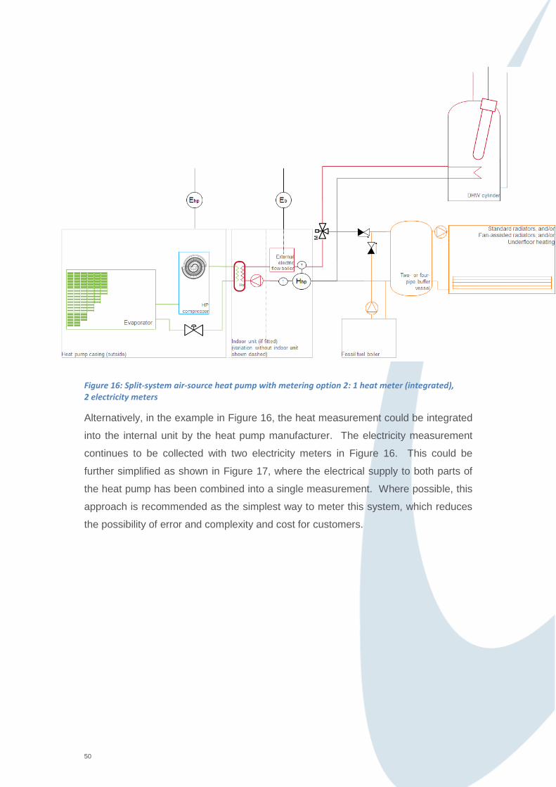
Figure 16: Split-system air-source heat pump with metering option 2: 1 heat meter (integrated), 2 electricity meters
Alternatively, in the example in Figure 16, the heat measurement could be integrated
into the internal unit by the heat pump manufacturer. The electricity measurement
continues to be collected with two electricity meters in Figure 16. This could be
further simplified as shown in Figure 17, where the electrical supply to both parts of
the heat pump has been combined into a single measurement. Where possible, this
approach is recommended as the simplest way to meter this system, which reduces
the possibility of error and complexity and cost for customers.

51
Figure 17: Split-system air-source heat pump with metering option 3: 1 heat meter (integrated), 1 electricity meter
52
Annex D: Fundamentals of heat metering and key points to consider
Heat meters, as specified under the Measuring Instruments Directive [2] have three
components; a flow measuring device, a pair of temperature sensors (to measure the
temperatures in the flow and return pipes) and a calculator or integrator.
Meters can be sold as combined units where all three components have been
matched by the manufacturer or as semi-combined where the components are
separate but sold as a kit. Alternatively individual components are sold that are
matched and integrated on-site by the MCS Contractor, though this makes the MCS
Contractor liable for ensuring that all components have been specified by a
manufacturer as compatible.
Flow meters can be designed to record flow using several different techniques.
Some of the most common include turbine flow meters which measure the rate of
rotation of a turbine placed within the flow; ultrasonic meters which record the speed
of sound within the flow or vortex meters which detect oscillations as a result of
vortices formed by forcing flow past a bluff body. Other models of flow meter are
available on the market.
A matched pair of temperature sensors are required to calculate the temperature
difference between two points. This is commonly achieved through matched pairs of
platinum resistance thermometers fitted into pockets within the flow. It is very
important that the temperature pair selected for a site is designed to measure
temperature differences expected at the specific points of heat measurement in order
for the measurement error not to exceed manufacturer’s designs.
A calculator unit processes the temperature and flow values using physical properties
of the fluid stored within the unit. Typically, this could include specific heat capacity
of the fluid, density of the fluid or other parameters as appropriate for the flow meter
2http://eur-
lex.europa.eu/LexUriServ/LexUriServ.do?uri=OJ:L:2004:135:0001:0080:EN:PDF
Directive 2004/22/EC of the European Parliament and of the Council of 31 March 2004 on
measuring instruments

53
in question. The calculation unit may also be responsible for storing data and
displaying readings to the customer and therefore should be placed in a location
where a customer can view the display panel.
When installing heat meters or selecting locations for isolation valves as part of
making a system meter-ready, there are several key points to consider.
Flow meter:
1. Is the flow meter sufficiently far from pumps or other features that will have a
significant impact on the flow?
Different types of flow meters have different sensitivities to pumps, double bends or
other flow disturbances. Meter manufacturers will provide guidance to support the
installation of their meters.
2. Is the orientation of the flow meter correct?
3. A flow meter must be selected with careful consideration so that qp (the
highest value of flow rate of the heat conveying liquid that is permitted permanently
for the heat meter to function correctly), and qi (the lowest value of flow rate that is
permitted for the heat meter to function correctly) and qs (the highest value of flow
rate that is permitted for short periods of time for the heat meter to function) are
appropriate for the system being measured.
4. Pay particular attention to the impact on system pressure as a result of flow
meter selection and installation of isolation valves.
Temperature sensors-
1. Temperature sensor pairs cannot be separated. Do not shorten or extend the
temperature sensor cables. This will change their electrical resistance and have an
impact on the readings that come from them.
2. Are the temperature sensors installed appropriately within the flow, e.g. within
a pocket in the pipework?
3. Are the cables of the temperature sensors exposed to sources of
electromagnetic interference, beyond the design specifications?

54
Calculation unit-
1. Is the calculation unit recording in the appropriate units for a Customer?
2. Does the Customer know how to read the heat meter to enable them to
submit meter readings for the RHI?
3. Is the calculator unit exposed to sources of electromagnetic disturbance
beyond the specifications?
4. If the calculator unit is outside then is it installed in accordance with
manufacturer’s instructions?

55
Annex E: Worked examples of requirements for Metering and
Monitoring Service Packages
In the following, there are a number of simplified examples to illustrate the sensor
requirements for potential Metering and Monitoring Service Packages. A key for the
types of meters and sensors is shown below:
Worked Example 1: An air-source heat pump providing space heating and
domestic hot water
The following example works through the required Metering and Monitoring Service
Package for a 10 kW air-source heat pump that is capable of modulating its heat
output to a minimum of 4 kW. The system is connected to a domestic hot water
cylinder with a 2 kW immersion element for the domestic hot water. The heat pump
has a design SPF of 2.7:
Heat meter, including flow meter (H part) and two temperature sensors
Temperature sensor
Electricity meter

56
Figure 18: Worked Example 1: ASHP
One metering arrangement that fulfils the specified criteria is shown in Figure 19.

57
Figure 19: Worked Example 1: ASHP with metering option 1
Where:
Ehp = electrical supply to the heat pump;
Edhw = electrical supply to immersion heating in domestic hot water cylinder;
Hhp = heat output from heat pump
Tsf = space flow temperature;
Twf = domestic hot water flow temperature;
Tin = internal air temperature in at least one location in the dwelling;
Text = external air temperature.
There is no gas or oil input so no gas or oil metering is required.
All data must be logged on at least a 2-minute time period.
Alternatively, the manufacturer may be able to integrate some of the metering in
Figure 19 into their unit, in which case the metering arrangement in Figure 20 may be
feasible.

58
Figure 20: Worked Example 1 - ASHP with metering option 2
Given that excessive electricity demand by a circulation pump can be expensive and
wastes energy, it is recommended that the electricity supply to the circulation pump is
measured even when it is not included in the heat meter reading.
Meter resolution
The resolution of a sensor is the smallest change it can detect in the quantity that it is
measuring.
The minimum resolution of heat meter required for space heating (Hhp in the diagram
in Figures 19 and 20) would be (using the resolution requirement expressed in Wh):
Here, the air-source heat pump has a minimum capacity of 4 kW. This means that in
2 minutes, the heat pump can output approximately 133 Wh of heat:
This means that the required resolution of the heat meter is at least 4 Wh. A meter
resolution of 1 Wh would also fit this specification.

59
Using the table shown in Section 7 (copied below), we could alternatively have noted
that the minimum capacity of the heat pump is 4 kW and then used the table below to
pick out that the meter resolution required is likely to be 1 Wh.
Min non-zero heat
output (Min. H) (kW)
Smallest change that
must be measurable
Example heat meter
display
Min. H < 10 kW 1 Wh 00000.000 kWh
10kW ≤ Min. H < 100 kW 10 Wh 000000.00 kWh
100 kW ≤ Min H. 100 Wh 0000000.0 kWh
[All meters measuring
draw-off from a DHW
cylinder]
10 Wh 000000.00 kWh
The minimum resolution of the electricity meter can be calculated in a similar
manner. Taking the design SPF of 2.7 and a heat output of 133 Wh in 2 minutes, the
electrical supply over 2 minutes can be estimated as 49 Wh. Putting this into the
equation below:
the minimum required resolution is 1.5 Wh. Therefore, a meter resolution of 1 Wh
would fit the criteria.
Similarly, the electricity meter for the immersion heating would need a meter capable
of resolving 2 Wh as a minimum resolution (making a 1 Wh meter resolution eligible).

60
Worked Example 2: A ground-source heat pump with integrated domestic hot water
cylinder
The following works through the specification for a (fixed-speed) 15 kW ground-
source heat pump (design SPF = 4.1) represented by the schematic shown in Figure
21:
Figure 21: Worked Example 2 – GSHP with integrated cylinder
One way to meet the eligibility criteria for MMSPs would be through the metering
arrangement shown in Figure 22:

61
Figure 22: Worked Example 2 - GSHP with integrated cylinder and metering option 1
Where:
Ehp = heat pump electrical supply;
Hdhw = domestic hot water heat output;
Hhp = space heating heat output;
Tgf = ground loop flow temperature;
Tgr = ground loop return temperature;
Twf = domestic hot water flow temperature;
Tsf = space heating flow temperature;
Tin = internal temperature in at least one location in the dwelling.
There is no gas or oil input so no gas or oil metering is required.
An alternative arrangement, where the manufacturer has been able to integrate the
heat meter into the heat pump unit is shown below:

62
Figure 23: Worked Example 2 - GSHP with integrated cylinder and metering option 2
In order for the package in Figure 23 to present the most useful information to
customers, it is recommended that the electrical supply to the internal electric flow
boiler is measured as this provides very useful information to understand how well
the heat pump is operating and to explain a customer’s bills.
All of the data must be logged on at least a 2-minute time period.
Again, the example fulfils the main criteria of the metering system which is to record
energy flows and provide key diagnostic temperature data to understand how well
the system is operating.
Meter resolution
The minimum resolution of the space heating heat meter (Hhp in Figures 22 and 23)
would be (using the resolution requirement as expressed in Wh):
Here, the ground-source heat pump has a (non-modulating) 15 kW capacity. This
means that in 2 minutes the heat pump can output approximately 500 Wh of heat:

63
This means that the required resolution of the heat meter is at least 15 Wh. A meter
resolution of 10 Wh or 1 Wh would fit this specification.
Using the table shown in Section 7, we could alternatively have noted that the
minimum capacity of the heat pump is 15 kW and then used the table below to pick
out that the meter resolution could be 10 Wh.
Min non-zero heat
output (Min. H) (kW)
Smallest change that
must be measurable
Example heat meter
display
Min. H < 10 kW 1 Wh 00000.000 kWh
10kW ≤ Min. H < 100 kW 10 Wh 000000.00 kWh
100 kW ≤ Min H. 100 Wh 0000000.0 kWh
[All meters measuring
draw-off from a DHW
cylinder]
10 Wh 000000.00 kWh
This is a simplified example where the ground-source heat pump is not inverter-
driven and therefore is not capable of modulating its output. For a modulating output,
the minimum non-zero heat output in 2 minutes should be entered into the equation
to determine the required heat meter resolution instead of the heat that would be
output at the nominal capacity as shown in Worked Example 1.
The smallest change the heat meter for the domestic hot water (Hdhw in Figure 22)
shall be capable of detecting is 10Wh with the aim of recording short hot water draw-
offs as described in section 7.1.
The minimum resolution of the electricity meter can be calculated in a similar
manner. Taking the design SPF of 4.1 and a heat output of 500 Wh in 2 minutes, the
electrical supply over 2 minutes can be estimated as 122 Wh. Putting this into the
equation below:

64
the minimum required resolution is 3.66 Wh. Therefore, a meter resolution of 1 Wh
would meet the eligibility requirements.
Worked Example 3: A split-system air-source heat pump with back-up fossil fuel
boiler and immersion heating
The following works through an example of the Metering and Monitoring Service
Package specification for a (fixed-speed) 4kW split-system air-source heat pump with
a design SPF of 2.7. It has a 3kW auxiliary electric heater with its own separate
electricity supply. In addition, the system has a 24 kW back-up gas boiler (that is
capable of modulating down to 8 kW) and a 2 kW immersion heater for the domestic
hot water.
Figure 24: Worked Example 3 – Split-system ASHP with back-up fossil fuel boiler and an immersion element in the domestic hot water cylinder
The minimum intended criteria for this package includes the metering shown in
Figure 25.
All data needs to be logged on a 2-minute time period.

65
Figure 25: Worked Example 3 – Split-system ASHP with back-up fossil fuel boiler and possible metering
Where
Ehp = electrical supply to heat pump;
Eb = electrical supply to auxiliary electric boiler;
Edhw = electrical supply to immersion heating of domestic hot water cylinder;
Hhp = heat output from heat pump;
Hff = heat output from fossil fuel system;
Tsf = space heating flow temperature;
Twf = domestic hot water flow temperature;
Tin = internal temperature at at least one location in the dwelling;
Text = external temperature.
It would also be possible to combine the electricity measurements in this example so
that they are recorded by a single electricity meter. This simplifies the metering
arrangements. If the electricity meters are combined, the meter resolution would
need to be the better of the two calculations shown below.

66
Meter resolution
It is intended that the minimum resolution of heat meter required for space heating
(Hhp in Figure 25) would be (using the requirement as defined in Wh):
Here, the air-source heat pump has a (non-modulating) 4 kW capacity. This means
that in 2 minutes the heat pump can output approximately 133 Wh of heat:
This means that the required resolution of the heat meter is at least 4 Wh. A meter
resolution of 1 Wh would also fit this specification.
Using the table shown in Section 7, we could alternatively have noted that the
minimum capacity of the heat pump is 4 kW and then used the table below to pick
out that the meter resolution could be 1 Wh.
Min non-zero heat
output (Min. H) (kW)
Smallest change that
must be measurable
Example heat meter
display
Min. H < 10 kW 1 Wh 00000.000 kWh
10kW ≤ Min. H < 100 kW 10 Wh 000000.00 kWh
100 kW ≤ Min H. 100 Wh 0000000.0 kWh
[All meters measuring
draw-off from a DHW
cylinder]
10 Wh 000000.00 kWh
The lowest heat power output of the fossil fuel boiler is 8 kW. Therefore, using the
table above, this comes to a resolution of 1 Wh.
The minimum resolution of the Ehp electricity meter is calculated in a similar manner
as in the previous example. Taking the design SPF of 2.7 and a heat output of
133 Wh in 2 minutes, the electrical supply over 2 minutes can be estimated as
49 Wh. Putting this into the equation:

67
the minimum required resolution is 1.47 Wh. Therefore, it is anticipated that a meter
resolution of 1 Wh would meet the eligibility requirements.
The auxiliary electric heater has a capacity of 3 kW and therefore, when operating,
uses 100 Wh in 2 minutes. Therefore, using the same equation, the required
resolution of electricity meter is 3 Wh (a 1 Wh electricity meter would also deliver the
right resolution).
Similarly, the electricity meter for the immersion heating would need a meter capable
of resolving a smallest change of at least 2 Wh (making a 1 Wh meter resolution also
eligible).
Worked Example 4: A pellet biomass boiler providing space heating and domestic
hot water
This example comprises a 24 kW pellet biomass boiler (electrical ignition) providing
both space heating and domestic hot water. The system’s minimum heat output is
8 kW.
Figure 26: Worked Example 4 - Pellet biomass boiler providing space heating and domestic hot water

68
Based on the eligibility requirements, Figure 27 shows a possible metering
arrangement for this system:
Figure 27: Worked Example 4 - Pellet biomass boilers providing space heating and domestic hot water with possible metering
Where
EB = electrical supply to boiler;
HB = heat output from boiler;
Tsf = flow temperature of space heating;
Twf = flow temperature of domestic hot water;
Tin = internal temperature;
Text = external temperature.
All data must be logged on at least a 2-minute time period.
There is no gas or oil input to this system so no gas or oil metering is required.
Meter resolution
The minimum resolution of heat meter required for space heating (HB in figure 27)
would be (using the resolution requirement expressed in Wh):

69
Here, the biomass boiler has a capacity of 24 kW and the lowest rate of heat output
is 8 kW. This means that in 2 minutes, the minimum amount of heat that the boiler
can output is approximately 267 Wh:
This means that the required resolution of the heat meter is at least 8 Wh. A meter
resolution of 1 Wh will also fit this criterion.
Using the table shown in Section 7, we could alternatively have noted that the
minimum capacity of the biomass boiler is 8 kW and then used the table below to
pick out that the meter resolution could be 1 Wh.
Min non-zero heat
output (Min. H) (kW)
Smallest change that
must be measurable
Example heat meter
display
Min. H < 10 kW 1 Wh 00000.000 kWh
10kW ≤ Min. H < 100 kW 10 Wh 000000.00 kWh
100 kW ≤ Min H. 100 Wh 0000000.0 kWh
[All meters measuring
draw-off from a DHW
cylinder]
10 Wh 000000.00 kWh
The minimum electrical load of this particular biomass boiler at any one time is that
required to operate the circulation pumps that are integrated into the body of the
boiler. If the system in Figure 27 has 2 high efficiency circulation pumps, this comes
to approximately 80 W power consumption so the energy input to the system in
2 minutes is 2.7 Wh.

70
Using the formula, the minimum required resolution is 0.2 Wh. It may not be practical
to require metering at a resolution that is finer than 1 Wh and the most significant
electrical energy consumption of the boiler will be when it is operating at substantially
higher than this rate. Therefore, a meter resolution of 1 Wh is be the highest
resolution required for such systems. It is expected that electricity meters with a
resolution of 1 Wh will usually be required for biomass boilers.

71
AMENDMENTS ISSUED SINCE PUBLICATION
Document Number: Amendment Details: Date:
1.0 First Issue
16/12/2013
1.1 Update to definitions. 01/05/2015