Embed Size (px)
Citation preview
ANSA & META for Injection
Molding simulation
Injection Molding simulation is a complex engineering process
which poses challenges in creating correct models for the
essential analyses. The ANSA pre- processor and the META post-
processor offers all the required tools and methods to cover
plastics simulations, from CAD data and ready-to-run solver files,
to automated reports generation.
physics on screen
enabling technologies Simulation
White paper
physics on screen
ANSA & META for Injection Molding simulation
Injection Molding simulation is a complex engineering process. Apart from the plastic part
design, the simulation includes also the consideration of the moldbase along with the internal
system entities such as the coolant channels, the runner along with the gates and sprues.
These all affect the thermal conduction or the melt flow influencing the final product.
Inappropriate mold designs will eventually result in additional cost. Hence, a complete analysis
should include all these compartments.
What makes Injection Molding simulations tricky?
During simulations for injection molding, the first step is to translate and fix the CAD files.
Frequently, CAE engineers are required to create designs from scratch. The next step is the
mesh generation. The aim in this step is to maintain the complexity of the geometry, while
producing a good mesh quality. The mesh generation is almost always followed by the
necessary local modifications and fixes to achieve an optimum result.
Moreover, in most cases during the product design, the analysts are required to test
modifications in the geometry to achieve an optimum design.
Plastic parts analysis, from concept to the final product require a variety of engineering
inspections. This means that a CAD file will be subjected to numerous simulation analyses for
all disciplines and test scenarios. This requires the migration of the model among different
software for different analyses.
All information from the simulations is processed and assessed. Post- processing processes
usually require additional time to extract the information and generate the required reports.
BETA CAE Systems through its software products offers solutions that address effectively all
steps in successfully completing the simulation driven design of plastics products.
physics on screen
From the CAD to the pre- processor
The CAD-to-ANSA translators can process a wide range of formats while making sure that
important information coming from CAD is stored for use throughout the simulation process.
After importing the geometry by simply running automatic check and fix, typical geometry
errors are corrected while the great variety of tools will assist you in further changes on the
geometry.
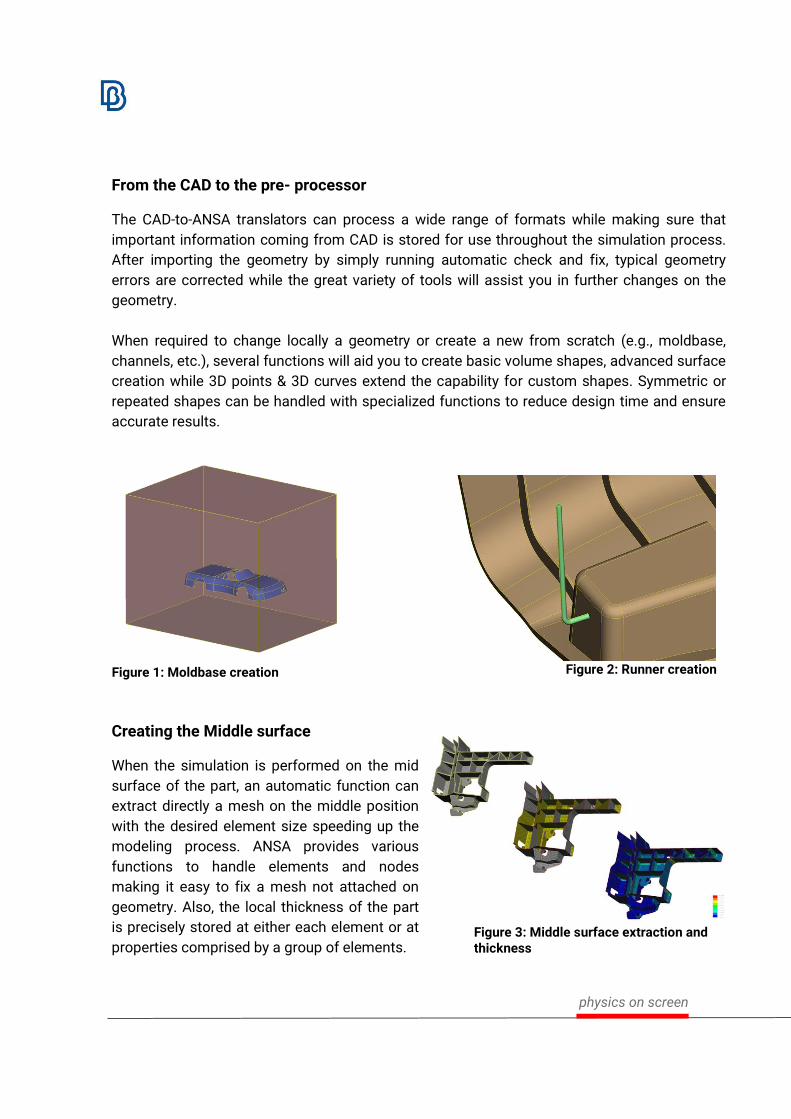
When required to change locally a geometry or create a new from scratch (e.g., moldbase,
channels, etc.), several functions will aid you to create basic volume shapes, advanced surface
creation while 3D points & 3D curves extend the capability for custom shapes. Symmetric or
repeated shapes can be handled with specialized functions to reduce design time and ensure
accurate results.
Creating the Middle surface
When the simulation is performed on the mid
surface of the part, an automatic function can
extract directly a mesh on the middle position
with the desired element size speeding up the
modeling process. ANSA provides various
functions to handle elements and nodes
making it easy to fix a mesh not attached on
geometry. Also, the local thickness of the part
is precisely stored at either each element or at
properties comprised by a group of elements.
Figure 1: Moldbase creation Figure 2: Runner creation
Figure 3: Middle surface extraction and thickness

physics on screen
Fixing the middle position and thickness assignment is performed via a specialized tool. With
this tool, every node is coupled with the information of the local volume geometry that
represents and this evolves many benefits:
• Both position and thickness information
is updated
• Moved nodes can be re-positioned with
a single click
• When changing nodal density (e.g.,
mesh reconstruction) the new nodes
are positioned correctly, while their
thickness is calculated
• This information is not lost after exiting
ANSA, since designated entities are
created and stored with the database.
Generating a high quality mesh
A good quality mesh can be generated through the advanced Batch Meshing tool, applied on
single or multiple parts. Both shell and solid mesh types can be pre-set in specific order with
individual settings, to achieve for example shell mesh, layered mesh, or tetra mesh of volume
geometry.
The Batch Mesh tool will ensure that:
• The Element size is maintained according to the given settings and tolerances
• The Mesh quality will be in line with the active quality criteria that are - among others -
specifically for Moldex3D and MOLDFLOW solvers
• Simplification of the original geometry segmentation may take place, to generate a
mesh of good quality without compromising the accuracy of the geometry
• Special treatments are applied on standard design features such as holes, tubes, and
fillets. This elevates the quality of the solver results on areas of high interest
Figure 4: Fixing the middle surface

physics on screen
Figure 5: Result mesh after Batch Meshing
Features can be further examined and treated under a special tool, for recognition, manual
definition, mesh or design changes. This accelerates the accurate capture of geometry
features, such as fillets and holes.
Figure 7: Drawing the recognized geometrical features
Figure 8: Detailed mesh on recognized fillets
Dedicated pure hexa mesh algorithms cover a wide range of geometry shapes, while for
advanced requirements polygonal shell and polyhedral solid elements are supported.
Figure 6: Layered mesh with tetras inside
physics on screen
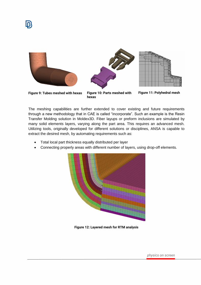
The meshing capabilities are further extended to cover existing and future requirements
through a new methodology that in CAE is called “incorporate”. Such an example is the Resin
Transfer Molding solution in Moldex3D. Fiber layups or preform inclusions are simulated by
many solid elements layers, varying along the part area. This requires an advanced mesh.
Utilizing tools, originally developed for different solutions or disciplines, ANSA is capable to
extract the desired mesh, by automating requirements such as:
• Total local part thickness equally distributed per layer
• Connecting properly areas with different number of layers, using drop-off elements.
Figure 12: Layered mesh for RTM analysis
Figure 9: Tubes meshed with hexas Figure 10: Parts meshed with hexas
Figure 11: Polyhedral mesh
physics on screen
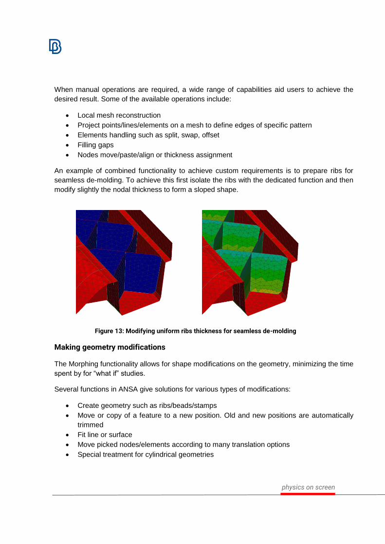
When manual operations are required, a wide range of capabilities aid users to achieve the
desired result. Some of the available operations include:
• Local mesh reconstruction
• Project points/lines/elements on a mesh to define edges of specific pattern
• Elements handling such as split, swap, offset
• Filling gaps
• Nodes move/paste/align or thickness assignment
An example of combined functionality to achieve custom requirements is to prepare ribs for
seamless de-molding. To achieve this first isolate the ribs with the dedicated function and then
modify slightly the nodal thickness to form a sloped shape.
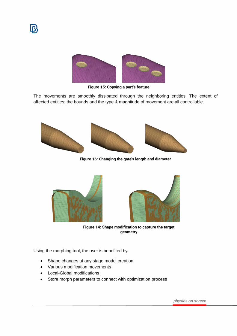
Making geometry modifications
The Morphing functionality allows for shape modifications on the geometry, minimizing the time
spent by for “what if” studies.
Several functions in ANSA give solutions for various types of modifications:
• Create geometry such as ribs/beads/stamps
• Move or copy of a feature to a new position. Old and new positions are automatically
trimmed
• Fit line or surface
• Move picked nodes/elements according to many translation options
• Special treatment for cylindrical geometries
Figure 13: Modifying uniform ribs thickness for seamless de-molding
physics on screen
The movements are smoothly dissipated through the neighboring entities. The extent of
affected entities; the bounds and the type & magnitude of movement are all controllable.
Using the morphing tool, the user is benefited by:
• Shape changes at any stage model creation
• Various modification movements
• Local-Global modifications
• Store morph parameters to connect with optimization process
Figure 15: Copying a part's feature
Figure 16: Changing the gate's length and diameter
Figure 14: Shape modification to capture the target geometry

physics on screen
Interaction with contemporary solvers for Injection Molding simulation
ANSA’s extended capabilities further minimize the interchange among different software and
also prepare model from CAD up to files ready to-be-solved. Moldex3D and MOLDFLOW are
such examples. This can be achieved as users can:
• Setup solver specific entities
• Exchange files with a variety of software formats, including .mfe, .msh and .udm
• Open ANSA with specialized environment according to the analysis it will take place
(e.g. Molding, Durability, CFD, etc.)
• Directly convert a model with solver specific entities by just switching the current solver
deck menu
• Map results from different solvers to different models
Specifically for the ABAQUS deck, it is possible to couple molding simulations for Fiber
Reinforced Plastic materials. Retrieving data from a Moldex3D or a MOLDFLOW files will
generate:
• Material orientation
• Anisotropic elasticity
• Anisotropic thermal expansion
Figure 17: Mapping fibers orientation, material elasticity and thermal expansion

physics on screen
Post- processing the results with META
The results can be processed in the META post-processor. Both geometry and results of
Moldex3D shell module and MOLDFLOW .xml can be read.
Using the embedded report composer, template-based reports in HTML, PostScript, MS Office
Powerpoint pptx and pdf format can be generated in a direct way.
The reports can be created interactively, taking advantage of the complete text editor in
addition to the interoperability between the different tools of META. Images and tables can be
easily added, with drag and drop, text boxes can be added and formatted, basic shapes can
be generated in the common “powerpoint” fashion.
The spreadsheet editor brings a new level in processing and exchanging data, as it can import
and export xlsx Excel files. It supports reading and creation of scatter charts, relative cell
references in formulas and conditional formatting of cells. Spreadsheet editor can be used as a
part of an automated procedure, as it can be parameterized by filling the cells with variables
and built-in functions.
Figure 18: Extended capabilities for composing reports in META

physics on screen
Achieving advanced automation
The results can be processed in the META post-processor. Both geometry and results of
Moldex3D
The support of ANSA and META Python API can automate specific operations or even
complete processes:
• Almost all functions are supported through scripting
• Create customized tools to cover your requirements
• Run ANSA and META in batch mode
• META session files store sequence of recorded commands
This capability extends the efficiency of process automation and also broadens capabilities
through the interaction of tools and functions.
Conclusions
Injection molding simulation can be thoroughly covered in pre- & post- processing using ANSA
and META. ANSA provides high efficiency and quality modeling offering great flexibility in
model handling. The Harmonic interaction between different tools & functions broadens the
capabilities and provide solutions for new methods and disciplines.
The ability to easily modify the shape and conduct different “what if analyses” minimizes effort
and the required time for the development of the optimum product.
Moreover, it is possible to map fiber orientation results from Moldex3D and MOLDFLOW and
prepare the model for a different type of analysis.
The project results and analyses can be easily summarized and pointed in a representative
report generated with META. This and even the entire pre-processing work can be fully
automated, reducing effort, time, and minimizing human error.
About BETA CAE Systems International AG
BETA is a simulation solutions provider, dedicated to the development
of state of the art software systems for CAE. For almost 30 years, we
have been developing tools and delivering services for the front-
runners in numerous sectors by listening to their needs and taking up
even the most demanding challenges. For more information on BETA
CAE systems, our products, and our services, visit www.beta-cae.com
Headquarters
D4 Business Village Luzern, Platz 4
CH-6039 Root D4,
Switzerland
+41 415453650
© 2019 BETA CAE Systems International AG • Features subject to change without
notice • All trademarks are property of their respective owners.
physics on screen
www.beta-cae.com