Embed Size (px)
DESCRIPTION
PSV datasheet normally we use for relief rate calcs
Citation preview

Premium Performance Direct SpringOperated Pressure Relief Valve
Series 60 and 80Series 60 and 80
Premium Performance Direct SpringOperated Pressure Relief Valve
ANDERSON GREENWOOD
Anderson GreenwoodPremium Performance Direct Spring Valves - Series 60 and 80
© 1996/rev. 2000, Anderson Greenwood Crosby reserves the right to change product designs and specifications without notice. i
Contents
Direct Spring Operated, Pressure Relief Valves
Features and Benefits ....................................................................... 1Overview ........................................................................................... 2 - 3
Sizing
How to Size a Valve .......................................................................... 4Sizing Formulas ................................................................................ 5 - 9Physical Properties ........................................................................... 10 - 14Conversion Tables ............................................................................. 15 - 17
Ordering
How to Finalize Your Selection ......................................................... 18Pressure and Temperature Ratings .................................................. 19 - 22Dimensions and Weights .................................................................. 23 - 35Materials of Construction .................................................................. 36 - 42Additional Information ....................................................................... 43Model Number Selection Tables ....................................................... 44 - 46Accessories and Options .................................................................. 47
Appendix
Operation – Types 81, 83 and 86 ..................................................... 48 - 49Operation – Types 81P, 61, 63B and 83F ......................................... 50 - 51Capacity Tables ................................................................................. 52 - 59Seat Tightness Performance ............................................................. 60
Q S 9 0 0 0
LLO
YD
'SR
EGIS
TER QUALITYA
SSUR
AN
CE
Premium Performance Direct Spring OperatedPressure Relief Valve
Series 60 and 80 CatalogRevised September 2000Catalog: 60/80 DS-US.96
ANDERSON GREENWOOD

Anderson GreenwoodPremium Performance Direct Spring Valves - Series 60 and 80
© 1996/rev. 2000, Anderson Greenwood Crosby reserves the right to change product designs and specifications without notice. 1
• Bubble-tight seating performanceallows maximum system throughputand system optimization.
• Standard soft seated design bubble-tight for repeated cycles, resulting inlow long-term maintenance costs. Nolapping of disks; inexpensive O-ringsare recommended spare parts.
• Powerful opening action at set pres-sure for safety valves allows for fulllift at set pressure. This reduces theprobability of freeze-up and also allowsthe valve to be set above the maximumallowable operating pressure (M.A.O.P.)for pipeline D.O.T. installations.
• Externally adjustable blowdown forsafety valves provides no interactionwith set pressure adjustment. No blow-down or warning ring access isrequired.
• Relief valves are balanced for backpressure without the use of bellowswhich reduces the initial cost of thevalve and the long-term maintenancecost.
• Meets ASME Section VIII require-ments which provides the userthird-party verification of valve capacityand performance.
Features and Benefits

Anderson GreenwoodPremium Performance Direct Spring Valves - Series 60 and 80
© 1996/rev. 2000, Anderson Greenwood Crosby reserves the right to change product designs and specifications without notice. 2
Product Overview
Anderson Greenwood’s premium perfor-mance direct spring operated pressurerelief valves use special internals and softseats to provide optimum, accurateperformance. Specific valve types areavailable for gas, vapor, liquid, gas or liq-uid thermal relief, and steam applications.
Types 81, 83, 86 Safety ValvesThe Type 81 direct spring operated safetyvalve, with an inert plastic seat, is suitablefor a wide range of products, pressures,and temperatures involving gas, vapor,and liquid or gas thermal relief applica-tions. It allows maintained tightness closeto set pressure, opens fully at set pressure,and provides a safe, external adjustmentfor short blowdown. The Type 81 valve isbest suited for cryogenic, high set pres-sure, and chemically active applications.
The Type 83 direct spring operated safetyvalve, with an elastomer seat, is ideal forgas processes that operate close to setpressure, for controlling valuable or pollut-ing gas products that should not be lost tothe atmosphere, and for liquid or gas ther-mal relief applications. It allows maintainedtightness close to set pressure, opens fullyat set pressure, and provides a safe, exter-nal adjustment for short blowdown. TheType 83 is best suited for hard-to-holdgases and vapors, and general gas orvapor service.
The Type 86 direct spring operated safetyvalve, with a thermoplastic seat, is designed for steam service. The perfor-mance of the valve allows processes tooperate close to set pressure withouteroding the seat causing leakage andhigh maintenance.
The huddling chamber of all three of thesevalve types has been optimized to providefull opening at set pressure. In addition,there is a unique, independent control ofthe blowdown via an external adjustmentscrew. The huddling chamber is powerfulenough to generate a lifting force to fullylift the disk (spindle) against the springforce, without any overpressure.
Closing is assisted by the development ofa controlled back pressure in the springchamber. This pressure helps the springclose the valve after actuating. Thisunique design uses this controlled backpressure in the spring chamber to pre-cisely control the magnitude of blowdownto a reasonable level.
Type 81P Relief ValveThe Type 81P is a soft-seated, balanced,direct spring operated pressure relief valve intended for liquid applications. Thisvalve is rated at full capacity at 10 percentoverpressure and meets the latest re-quirements of Section VIII, Division 1 ofthe ASME Unfired Pressure Vessel Code.
The Type 81P is very similar to the Type 81, but the internal nozzle, guide,and spindle assembly are made especiallyfor the unique demands of liquid service.The spindle assembly uses three replace-able sealing members: a speciallyengineered plastic seat and two elastomerseals. The two seals help balance againstback pressure and stabilize against de-structive chatter. The nozzle fits closelywith the guide, providing perfect alignmentfor the spindle. Multiple discharge holes inthe guide provide free discharge of the re-lieving flow to the valve outlet.
The spring chamber is isolated by theguide seal and the back pressure (balanc-ing) seal on the stem of the spindle, and isvented to the atmosphere. Thus, the valveremains fully balanced and operationalwithout the need for an expensive bellows.
The stem of the spindle has a sealing di-ameter equal to the seat-to-nozzle contactdiameter. This provides complete balanc-ing against the effects of superimposedback pressure.
The stabilizing ring consists of an O-ring, with a pressure passage that al-lows system pressure to pass through the seat retainer screw to force the O-ring against the guide. This provides avariable resistance to spindle movement,proportional to system pressure. The un-predictable chattering behavior of manyliquid safety relief valves is completelyeliminated by this pressure-energized sta-bilizing ring. The possibility of destructiveshock waves, which could damage pipingand associated pressure-containing mem-bers, is greatly reduced.
Type 61 and 63B Safety ValvesThe Types 61 and 63B are direct springoperated safety valves suitable for lowand medium set pressure gas, vapor, andliquid or gas thermal relief applications.Brass construction offers an economicalvalve for carbon dioxide, natural gas, andgeneral gas or vapor services. The Type61 is also suitable for cryogenic andchemically active applications.

Anderson GreenwoodPremium Performance Direct Spring Valves - Series 60 and 80
© 1996/rev. 2000, Anderson Greenwood Crosby reserves the right to change product designs and specifications without notice. 3
Preliminary Selection Guide for Valve Type (Page 4)
Compare Selected Orifice with AvailableMaterials of Construction and Pressure Temperature Limits
(Pages 19-21)
Size for Required Orifice (Page 4)
Step 1
Accessories and Options (Page 45)
Step 4
Overview
Three steps make it easy to select, sizeand order the valve. The flow of the threesteps is described below.
Step 1, Preliminary valve selection: helpsyou determine the type of valve that bestsuits your application.
Step 2, Sizing: provides the informationyou need to choose the correct valve ori-fice area.
Step 3, Ordering: explains how to finalizevalve selection and order the specificmodel number, after you have chosen theappropriate valve type and size.
Construct Model Number(Pages 42-44)
Step 2
Step 3

Anderson GreenwoodPremium Performance Direct Spring Valves - Series 60 and 80
© 1996/rev. 2000, Anderson Greenwood Crosby reserves the right to change product designs and specifications without notice. 4
Preliminary Selection Guide
Applications Body MaterialValve Gas/ Gas/Liquid Seat Set Relieving BalancedType Vapor Liquid Thermal Steam Type Brass CS SS Pressure Temperature for Back
Relief psig [barg] °F [°C] Pressure
81 X X Plastic X X X 50 to 10,000 [3.45 to 689.5] -423°F to 500°F [-253°C to 260°C] N
81P X X Plastic X X X 50 to 6,000 [3.45 to 413.7] -40°F to 400°F [-40°C to 205°C] Y
83 X X O-ring X X X 20 to 2,000 [1.40 to 137.9] -40°F to 550°F [-40°C to 288°C] N
86 X Plastic X X X 50 to 720 [3.45 to 49.6] -423°F to 515°F [-253°C to 268°C] N
61 X X Plastic X 30 to 500 [2.07 to 34.5] -320°F to 400°F [-196°C to 205°C] N
63B X X O-ring X 37 to 531 [2.55 to 36.6] -40°F to 400°F [-40°C to 205°C] N
Note
1. Minimum and maximum set pressures maynot be available in all orifice sizes (seepages 19 - 22).
Pressure relief valves are selected on thebasis of their ability to meet an expectedrelieving condition and flowing a sufficientamount of fluid to prevent excessive pres-sure increase. This means that the size ofthe valve orifices must be calculated tak-ing the required flow, lading fluidproperties, and other factors into consid-eration.
To select the minimum required orificearea that will flow the required capacity ofthe system you wish to protect, pleaserefer to the following information, whichappears in this section:
1. Sizing formulas
2. Physical properties of the fluid to berelieved
3. Capacities of different orifice areas at different pressures
4. Conversion tables to aid calculations
Once you have determined the requiredorifice area for your service conditions,refer to Ordering, pages 18 through 44, toselect a specific valve model number.
Orifice Areas and NozzleCoefficientThe orifice areas and nozzle coefficientsfor all Series 80 valves are tabulated inthe table below.
These values are derived from the valuescertified by the National Board of Boilerand Pressure Vessel Inspectors, in accor-dance with Section VIII, Division 1 of theASME Pressure Vessel Code.
Verification of SizingOrifice area calculations are made and/orverified whenever sufficient data is provid-ed. If no data is furnished, the sizeselection responsibility will remain totallywith the purchaser.
Sizing – How to Size a Valve
Nozzle Coefficient and Available Orifice Sizes, in2 [cm2]
Valve K 0.049 0.077 0.110 0.150 0.196 0.307 0.503 0.785 1.287Type [0.316] [0.497] [0.710] [0.968] [1.265] [1.981] [3.245] [5.065] [8.303]
(-4) (-5) (-6) (-7) (-8 or E) (F) (G) (H) (J)
81 0.816 X X X X X X X
81P 0.720 X X X X
83 0.816 X X X X X X X
86 0.816 X X X X
61 0.877 X
63B 0.847 X X

Anderson GreenwoodPremium Performance Direct Spring Valves - Series 60 and 80
© 1996/rev. 2000, Anderson Greenwood Crosby reserves the right to change product designs and specifications without notice. 5
Vapors or Gases (capacity in SCFM)1
______V √ MTZ
A = –––––––––––6.32 CKP1
Vapors or Gases (capacity in lb/hr )1
___W √ TZ
A = –––––––––––__CKP1 √ M
English Sizing FormulasOrifice area calculations are made and/orverified whenever sufficient data is provid-ed. If no data is furnished, the sizeselection responsibility will remain totallywith the purchaser.
V = Required capacity, SCFM
W = Required capacity, lb/hr
VL = Required capacity, gpm
G = Specific gravity of liquid at flowing temperature referred to water =1.00 at 70°F (see PhysicalProperties on pages 12 - 14)
M = Molecular weight of vapor or gas (M = 29 x G, see PhysicalProperties on pages 10 - 11)
T = Relief temperature, °R (°R = °F + 460)
Z = Compressibility factor (if unknown,assume Z = 1.0)
Cpk = Specific heat ratio k = –––––
CV
Note
1. As is accepted industry practice, built-upback pressure for conventional (unbal-anced) gas or steam valves should notexceed 10 percent.
Steam (capacity in lb/hr )1
WA = ––––––––––––
51.5 K P1 Ks
Liquids (capacity in gpm)___
VL √ GA = –––––––––––––––––––––––––________
38 K KP KW KV √ PA – PB
C = Gas constant based on k (if un-known, assume C = 315; seePhysical Properties on pages 10 - 11; also see page 8)
K = Nozzle coefficient for 90 percent of actual capacity, derived fromNational Board Certified Testing(see page 4)
P1 = Inlet flowing pressure, psia= Set pressure - inlet pressure loss +allowable overpressure + 14.7
PA = Inlet flowing pressure, psig = Set pressure - inlet pressure loss +allowable overpressure
PB = Back pressure - psig
Kp = Overpressure correction factor, 1.0
Kw = Back pressure correction factor (see page 7)
Kv = Viscosity correction factor (see page 7)
Ks = Superheat correction factor (for sat-urated steam, Ks = 1.0, refer to Tableon page 9)
Sizing – English Sizing Formulas
Anderson GreenwoodPremium Performance Direct Spring Valves - Series 60 and 80
© 1996/rev. 2000, Anderson Greenwood Crosby reserves the right to change product designs and specifications without notice. 6
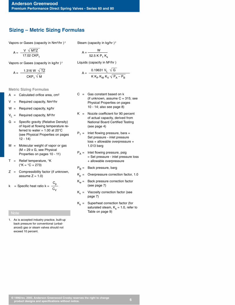
Vapors or Gases (capacity in Nm3/hr )1
______V √ MTZ
A = –––––––––––17.02 CKP1
Vapors or Gases (capacity in kg/hr )1
___1.316 W √ TZ
A = –––––––––––––––__CKP1 √ M
Metric Sizing FormulasA = Calculated orifice area, cm2
V = Required capacity, Nm3/hr
W = Required capacity, kg/hr
VL = Required capacity, M3/hr
G = Specific gravity (Relative Density)of liquid at flowing temperature re-ferred to water = 1.00 at 20°C(see Physical Properties on pages12 - 14)
M = Molecular weight of vapor or gas (M = 29 x G, see PhysicalProperties on pages 10 - 11)
T = Relief temperature, °K (°K = °C + 273)
Z = Compressibility factor (if unknown,assume Z = 1.0)
Cpk = Specific heat ratio k = –––––
CV
Note
1. As is accepted industry practice, built-upback pressure for conventional (unbal-anced) gas or steam valves should notexceed 10 percent.
Steam (capacity in kg/hr )1
WA = ––––––––––––
52.5 K P1 Ks
Liquids (capacity in M3/hr )___
0.19631 VL √ GA = –––––––––––––––––––––––––________
K KP KW KV √ PA – PB
C = Gas constant based on k(if unknown, assume C = 315; seePhysical Properties on pages 10 - 14; also see page 8)
K = Nozzle coefficient for 90 percent of actual capacity, derived fromNational Board Certified Testing(see page 4)
P1 = Inlet flowing pressure, bara = Set pressure - inlet pressure loss + allowable overpressure +1.013 barg
PA = Inlet flowing pressure, psig = Set pressure - inlet pressure loss+ allowable overpressure
PB = Back pressure, barg
Kp = Overpressure correction factor, 1.0
Kw = Back pressure correction factor(see page 7)
Kv = Viscosity correction factor (seepage 7)
Ks = Superheat correction factor (forsaturated steam, Ks = 1.0, refer toTable on page 9)
Sizing – Metric Sizing Formulas
Anderson GreenwoodPremium Performance Direct Spring Valves - Series 60 and 80
© 1996/rev. 2000, Anderson Greenwood Crosby reserves the right to change product designs and specifications without notice. 7
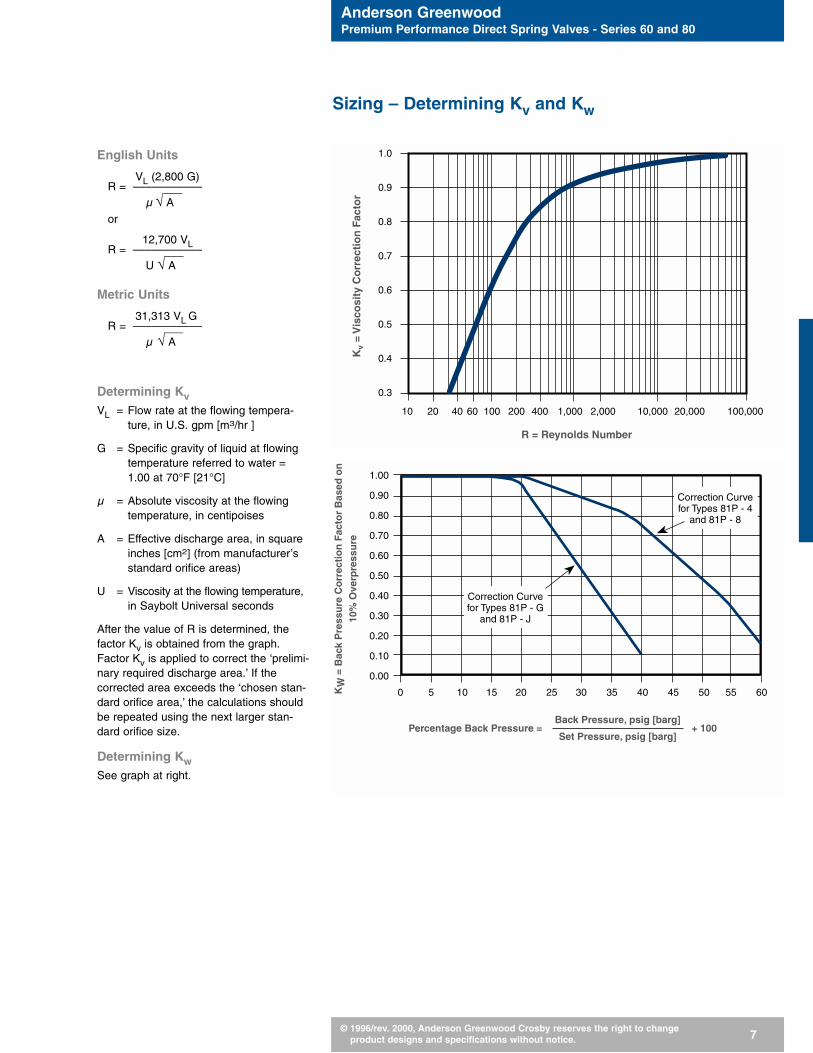
English Units
VL (2,800 G)R = –––––––––––___
µ √ A
or
12,700 VLR = –––––––––––___U √ A
Metric Units
31,313 VL GR = –––––––––––___
µ √ A
Determining KvVL = Flow rate at the flowing tempera-
ture, in U.S. gpm [m3/hr ]
G = Specific gravity of liquid at flowingtemperature referred to water =1.00 at 70°F [21°C]
µ = Absolute viscosity at the flowingtemperature, in centipoises
A = Effective discharge area, in squareinches [cm2] (from manufacturer’sstandard orifice areas)
U = Viscosity at the flowing temperature,in Saybolt Universal seconds
After the value of R is determined, thefactor Kv is obtained from the graph.Factor Kv is applied to correct the ‘prelimi-nary required discharge area.’ If thecorrected area exceeds the ‘chosen stan-dard orifice area,’ the calculations shouldbe repeated using the next larger stan-dard orifice size.
Determining KwSee graph at right.
Sizing – Determining Kv and Kw
1.0
0.9
0.8
0.7
0.6
0.5
0.4
0.3
10 20 40 60 100 200 400 1,000 2,000 10,000 20,000 100,000
R = Reynolds Number
Kv
= V
isco
sity
Co
rrec
tio
n F
acto
r
1.00
0.90
0.80
0.70
0.60
0.50
0.40
0.30
0.20
0.10
0.00
0
Percentage Back Pressure =
KW
= B
ack
Pre
ssu
re C
orr
ecti
on
Fac
tor
Bas
ed o
n10
% O
verp
ress
ure
5 10 15 20 25 30 35 40 45 50 55 60
Back Pressure, psig [barg]
Set Pressure, psig [barg]+ 100
Correction Curvefor Types 81P - 4
and 81P - 8
Correction Curvefor Types 81P - G
and 81P - J

Anderson GreenwoodPremium Performance Direct Spring Valves - Series 60 and 80
© 1996/rev. 2000, Anderson Greenwood Crosby reserves the right to change product designs and specifications without notice. 8
Determining C, based on k – Gas Constant, C
k C
1.00 315
1.02 318
1.04 320
1.06 322
1.08 324
1.10 327
1.12 329
1.14 331
1.16 333
1.18 335
1.20 337
1.22 339
1.24 341
1.26 343
1.28 345
1.30 347
1.32 349
1.34 351
1.36 352
1.38 354
1.40 356
1.42 358
1.44 359
1.46 361
1.48 363
1.50 364
k C
1.52 366
1.54 368
1.56 369
1.58 371
1.60 372
1.62 374
1.64 376
1.66 377
1.68 379
1.70 380
1.72 382
1.74 383
1.76 384
1.78 386
1.80 387
1.82 388
1.84 390
1.86 391
1.88 392
1.90 394
1.92 395
1.94 397
1.96 398
1.98 399
2.00 400
2.02 401
Sizing

Anderson GreenwoodPremium Performance Direct Spring Valves - Series 60 and 80
© 1996/rev. 2000, Anderson Greenwood Crosby reserves the right to change product designs and specifications without notice. 9
Steam Super Heat Correction Factor, Ks
Set Saturated Total Steam Temperature in, °F [°C]Pressure Steam Temp 300 320 340 360 380 400 420 440 460 480 500 520 540 560
psig [barg] °F [°C] [149] [160] [171] [182] [193] [205] [216] [227] [238] [249] [260] [271] [282] [293]
50 3.5 298 [148] 1.00 1.00 1.00 0.99 0.99 0.98 0.97 0.96 0.95 0.94 0.93 0.92 0.91 0.90
60 4.1 308 [153] 1.00 1.00 0.99 0.99 0.98 0.97 0.96 0.95 0.94 0.93 0.92 0.91 0.90
80 5.5 324 [162] 1.00 1.00 0.99 0.99 0.98 0.97 0.96 0.94 0.93 0.92 0.91 0.90
100 6.9 338 [170] 1.00 1.00 0.99 0.98 0.97 0.96 0.95 0.94 0.93 0.92 0.91
120 8.3 350 [177] 1.00 1.00 0.99 0.98 0.97 0.96 0.95 0.94 0.93 0.92 0.91
140 9.7 361 [183] 1.00 1.00 0.99 0.98 0.96 0.95 0.94 0.93 0.92 0.91
160 11.0 371 [188] 1.00 1.00 0.99 0.98 0.97 0.95 0.94 0.93 0.92 0.91
180 12.4 380 [193] 1.00 0.99 0.98 0.97 0.96 0.95 0.93 0.92 0.91
200 13.8 388 [198] 1.00 0.99 0.99 0.97 0.96 0.95 0.93 0.92 0.91
220 15.2 395 [202] 1.00 1.00 0.99 0.98 0.96 0.95 0.94 0.93 0.92
240 16.6 403 [206] 1.00 0.99 0.98 0.97 0.95 0.94 0.93 0.92
260 17.9 409 [210] 1.00 0.99 0.98 0.97 0.96 0.94 0.93 0.92
280 19.3 416 [213] 1.00 1.00 0.99 0.97 0.96 0.95 0.93 0.92
300 20.7 422 [217] 1.00 0.99 0.98 0.96 0.95 0.93 0.92
350 24.1 436 [225] 1.00 1.00 0.99 0.97 0.96 0.94 0.93
400 27.6 448 [231] 1.00 0.99 0.98 0.96 0.95 0.93
450 31.0 460 [238] 1.00 0.99 0.97 0.96 0.94
500 34.5 470 [243] 1.00 0.99 0.98 0.96 0.94
550 37.9 480 [249] 1.00 0.99 0.97 0.95
600 41.4 489 [254] 1.00 0.99 0.98 0.96
650 44.8 497 [258] 1.00 0.99 0.97
700 48.3 506 [263] 1.00 0.99 0.97
750 51.7 513 [267] 1.00 1.00 0.98
Sizing

Anderson GreenwoodPremium Performance Direct Spring Valves - Series 60 and 80
© 1996/rev. 2000, Anderson Greenwood Crosby reserves the right to change product designs and specifications without notice. 10
Physical Properties
M kCGas or Vapor Molecular Specific
Gas ConstantWeight Heat Ratio
Acetone 58.08 1.12 329
Acetylene (Ethyne) 26.04 1.26 343
Air 28.97 1.40 356
Ammonia, Anhydrous 17.03 1.31 348
Argon 39.95 1.67 378
Benzene (Benzol or Benzole) 78.11 1.12 329
Boron Trifluoride 67.82 1.20 337
Butadiene-1,3 (Divinyl) 54.09 1.12 329
Butane-n (Normal Butane) 58.12 1.09 326
Butylene (1-Butene) 56.11 1.11 328
Carbon Dioxide 44.01 1.29 346
Carbon Disulfide (C. Bisulfide) 76.13 1.21 33
Carbon Monoxide 28.01 1.40 356
Carbon Tetrachloride 153.82 1.11 328
Chlorine 70.91 1.36 353
Chloromethane (Methyl Chloride) 50.49 1.28 345
Cyclohexane 84.16 1.09 326
Cyclopropane (Trimethylene) 42.08 1.11 328
Decane-n 142.29 1.04 320
Diethylene Glycol (DEG) 106.17 1.07 323
Dimethyl Ether (Methyl Ether) 46.07 1.11 328
Dowtherm A 165.00 1.05 321
Dowtherm E 147.00 1.00 315
Ethane 30.07 1.19 336
Ethyl Alcohol (Ethanol) 46.07 1.13 330
Ethylene (Ethene) 28.05 1.24 341
Ethylene Glycol 62.07 1.09 326
Ethylene Oxide 44.05 1.21 338
Fluorocarbons:
12, Dichlorodifluoromethane 120.93 1.14 331
13, Chlorotrifluoromethane 104.47 1.17 334
13B1, Bromotrifluoromethane 148.93 1.14 331
22, Chlorodifluoromethane 86.48 1.18 335
115, Chloropentafluoroethane 154.48 1.08 324
Glycerine (Glycerin or Glycerol) 92.10 1.06 322
Helium 4.00 1.67 378
Heptane 100.21 1.05 321
Sizing

Anderson GreenwoodPremium Performance Direct Spring Valves - Series 60 and 80
© 1996/rev. 2000, Anderson Greenwood Crosby reserves the right to change product designs and specifications without notice. 11
Physical Properties
M kCGas or Vapor Molecular Specific
Gas ConstantWeight Heat Ratio
Hexane 86.18 1.06 322
Hydrogen 2.02 1.41 357
Hydrogen Chloride, Anhydrous 36.46 1.41 357
Hydrogen Sulfide 34.08 1.32 349
Isobutane (2-Methylpropane) 58.12 1.10 327
Isoprene (2-Methyl-1, 3 Butadiene) 68.12 1.09 326
Isopropyl Alcohol (Isopropanol) 60.10 1.09 326
Krypton 83.80 1.71 380
Methane 16.04 1.31 348
Methyl Alcohol (Methanol) 32.04 1.20 337
Methylamines, Anhydrous
Monomethylamine (Methylamine) 31.06 1.02 317
Dimethylamine 45.08 1.15 332
Trimethylamine 59.11 1.18 335
Methyl Mercapton (Methanethiol) 48.11 1.20 337
Napthalene (Napthaline) 128.17 1.07 323
Natural Gas (specific gravity = 0.60) 17.40 1.27 344
Neon 20.18 1.64 375
Nitrogen 28.01 1.40 356
Nitrous Oxide 44.01 1.30 347
Octane 114.23 1.05 321
Oxygen 32.00 1.40 356
Pentane 72.15 1.07 323
Propadiene (Allene) 40.07 1.69 379
Propane 44.10 1.13 330
Propylene (Propene) 42.08 1.15 332
Propylene Oxide 58.08 1.13 330
Styrene 104.15 1.07 323
Sulfur Dioxide 64.06 1.28 345
Sulfur Hexafluoride 146.05 1.09 326
Steam 18.02 1.31 348
Toluene (Toluol or Methylbenzene) 92.14 1.09 326
Triethylene Glycol (TEG) 150.18 1.04 320
Vinyl Chloride Monomer (VCM) 62.50 1.19 336
Xenon 131.30 1.65 376
Xylene (p-Xylene) 106.17 1.07 323
Sizing

Anderson GreenwoodPremium Performance Direct Spring Valves - Series 60 and 80
© 1996/rev. 2000, Anderson Greenwood Crosby reserves the right to change product designs and specifications without notice. 12
Physical Properties
GLiquid Specific Gravity °F [°C]
Water = 1
Acetaldehyde 0.779 68 20
Acetic Acid 1.051 68 20
Acetone 0.792 68 20
Ammonia, Anhydrous 0.666 68 20
Automotive Crankcase and Gear Oils:
SAE-5W Through SAE 150 0.88-0.94 60 15.6
Beer 1.01 60 15.6
Benzene (Benzol) 0.880 68 20
Boron Trifluoride 1.57 -148 -100
Butadiene - 1, 3 0.622 68 20
Butane-n (Normal Butane) 0.579 68 20
Butylene (1-Butene) 0.600 68 20
Carbon Dioxide 1.03 -4 -20
Carbon Disulfide (C. Bisulfide) 1.27 68 20
Carbon Tetrachloride 1.60 68 20
Chlorine 1.42 68 20
Chloromethane (Methyl Chloride) 0.921 68 20
Crude Oils:
32.6 Deg API 0.862 60 15.6
35.6 Deg API 0.847 60 15.6
40 Deg API 0.825 60 15.6
48 Deg API 0.79 60 15.6
Cyclohexane 0.780 68 20
Cyclopropane (Trimethylene) 0.621 68 20
Decane-n 0.731 68 20
Diesel Fuel Oils 0.82-0.95 60 15.6
Diethylene Glycol (DEG) 1.12 68 20
Dimethyl Ether (Methyl Ether) 0.663 68 20
Dowtherm A 0.998 68 20
Dowtherm E 1.087 68 20
Ethane 0.336 68 20
Ethyl Alcohol (Ethanol) 0.79 68 20
Ethylene (Ethene) 0.569 -155 -104
Ethylene Glycol 1.115 68 20
Ethylene Oxide 0.901 68 20
Sizing
Anderson GreenwoodPremium Performance Direct Spring Valves - Series 60 and 80
© 1996/rev. 2000, Anderson Greenwood Crosby reserves the right to change product designs and specifications without notice. 13
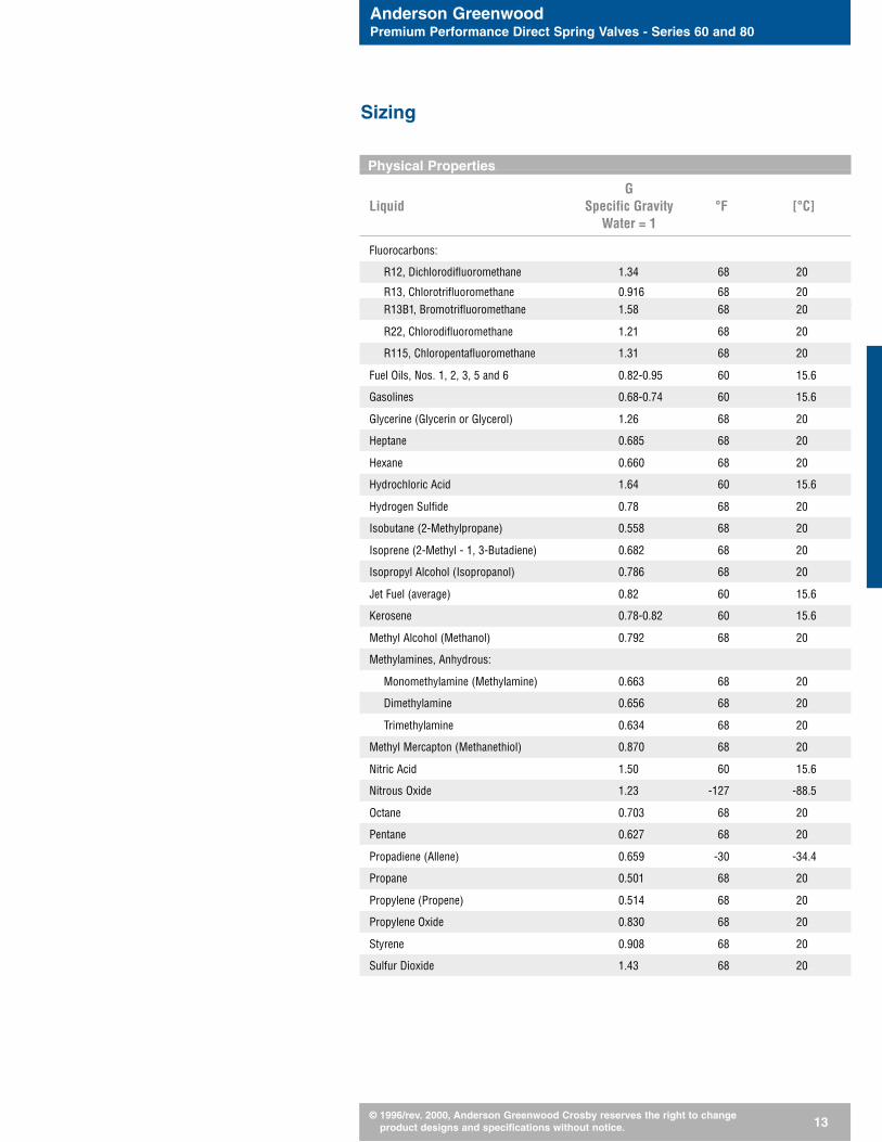
Physical Properties
GLiquid Specific Gravity °F [°C]
Water = 1
Fluorocarbons:
R12, Dichlorodifluoromethane 1.34 68 20
R13, Chlorotrifluoromethane 0.916 68 20R13B1, Bromotrifluoromethane 1.58 68 20
R22, Chlorodifluoromethane 1.21 68 20
R115, Chloropentafluoromethane 1.31 68 20
Fuel Oils, Nos. 1, 2, 3, 5 and 6 0.82-0.95 60 15.6
Gasolines 0.68-0.74 60 15.6
Glycerine (Glycerin or Glycerol) 1.26 68 20
Heptane 0.685 68 20
Hexane 0.660 68 20
Hydrochloric Acid 1.64 60 15.6
Hydrogen Sulfide 0.78 68 20
Isobutane (2-Methylpropane) 0.558 68 20
Isoprene (2-Methyl - 1, 3-Butadiene) 0.682 68 20
Isopropyl Alcohol (Isopropanol) 0.786 68 20
Jet Fuel (average) 0.82 60 15.6
Kerosene 0.78-0.82 60 15.6
Methyl Alcohol (Methanol) 0.792 68 20
Methylamines, Anhydrous:
Monomethylamine (Methylamine) 0.663 68 20
Dimethylamine 0.656 68 20
Trimethylamine 0.634 68 20
Methyl Mercapton (Methanethiol) 0.870 68 20
Nitric Acid 1.50 60 15.6
Nitrous Oxide 1.23 -127 -88.5
Octane 0.703 68 20
Pentane 0.627 68 20
Propadiene (Allene) 0.659 -30 -34.4
Propane 0.501 68 20
Propylene (Propene) 0.514 68 20
Propylene Oxide 0.830 68 20
Styrene 0.908 68 20
Sulfur Dioxide 1.43 68 20
Sizing
Anderson GreenwoodPremium Performance Direct Spring Valves - Series 60 and 80
© 1996/rev. 2000, Anderson Greenwood Crosby reserves the right to change product designs and specifications without notice. 14
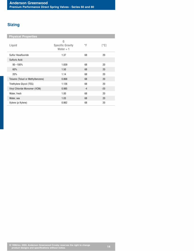
Physical Properties
GLiquid Specific Gravity °F [°C]
Water = 1
Sulfur Hexafluoride 1.37 68 20
Sulfuric Acid:
95 –100% 1.839 68 20
60% 1.50 68 20
20% 1.14 68 20
Toluene (Toluol or Methylbenzene) 0.868 68 20
Triethylene Glycol (TEG) 1.126 68 20
Vinyl Chloride Monomer (VCM) 0.985 -4 -20
Water, fresh 1.00 68 20
Water, sea 1.03 68 20
Xylene (p-Xylene) 0.862 68 20
Sizing
Anderson GreenwoodPremium Performance Direct Spring Valves - Series 60 and 80
© 1996/rev. 2000, Anderson Greenwood Crosby reserves the right to change product designs and specifications without notice. 15
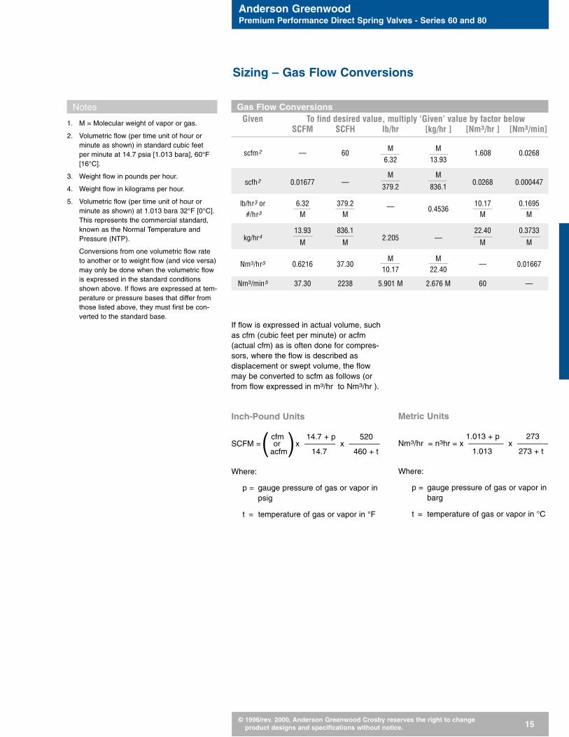
Gas Flow ConversionsGiven To find desired value, multiply ‘Given’ value by factor below
SCFM SCFH lb/hr [kg/hr ] [Nm3/hr ] [Nm3/min]
scfm2 — 60M M
1.608 0.02686.32 13.93
—M M
scfh2 0.01677 —379.2 836.1
0.0268 0.000447
lb/hr3 or 6.32 379.2 — 0.453610.17 0.1695
#/hr3 M M M M
13.93 836.1—
22.40 0.3733kg/hr4
M M2.205 —
M M
Nm3/hr5 0.6216 37.30M M
— 0.0166710.17 22.40
Nm3/min5 37.30 2238 5.901 M 2.676 M 60 —
Notes
1. M = Molecular weight of vapor or gas.
2. Volumetric flow (per time unit of hour orminute as shown) in standard cubic feet per minute at 14.7 psia [1.013 bara], 60°F[16°C].
3. Weight flow in pounds per hour.
4. Weight flow in kilograms per hour.
5. Volumetric flow (per time unit of hour orminute as shown) at 1.013 bara 32°F [0°C].This represents the commercial standard,known as the Normal Temperature andPressure (NTP).
Conversions from one volumetric flow rateto another or to weight flow (and vice versa) may only be done when the volumetric flow is expressed in the standard conditionsshown above. If flows are expressed at tem-perature or pressure bases that differ fromthose listed above, they must first be con-verted to the standard base.
If flow is expressed in actual volume, suchas cfm (cubic feet per minute) or acfm(actual cfm) as is often done for compres-sors, where the flow is described asdisplacement or swept volume, the flowmay be converted to scfm as follows (orfrom flow expressed in m3/hr to Nm3/hr ).
Inch-Pound Units
cfm 14.7 + p 520SCFM = or x ––––––– x –––––––(acfm) 14.7 460 + t
Where:
p = gauge pressure of gas or vapor inpsig
t = temperature of gas or vapor in °F
Metric Units
1.013 + p 273Nm3/hr = n3hr = x –––––––– x –––––––
1.013 273 + t
Where:
p = gauge pressure of gas or vapor inbarg
t = temperature of gas or vapor in °C
Sizing – Gas Flow Conversions

Anderson GreenwoodPremium Performance Direct Spring Valves - Series 60 and 80
© 1996/rev. 2000, Anderson Greenwood Crosby reserves the right to change product designs and specifications without notice. 16
Pressure ConversionGiven To find desired value, multiply ‘Given’ value by factor below
kPa psig kg/cm2 barg
kPa (kilopascal) — 0.1450 0.0102 0.0100
psig (pounds/in2)3 6.895 — 0.0703 0.06895
kg/cm2 (1)(kilograms/cm2) 98.07 14.22 — 0.9807
barg 100.00 14.50 1.020 —
Area ConversionGiven To find desired value, multiply ‘Given’ value by factor below
in2 ft2 mm2 cm2
in2 — 0.006944 645.16 6.4516
cm2 0.155 1.076 x 10⁻³ 100 —
ft2 144 — 92900 929
mm2 0.00155 1.076 x 10⁻⁵ — 0.01
Notes
1. Also expressed as kp/cm2 and kgf/cm2.
2. Normal Temperature and Pressure (NTP)Conditions are, at sea level, equal to 1.013bara or 1.033 kg/cm2 (kilograms force persquare centimeter absolute) at a base tem-perature of 32°F [0°C]. This differs slightlyfrom Metric Standard Conditions (MSC),which uses 1.013 bara 60°F [15°C] for thebase temperature.
3. Inch-Pound Standard Conditions are, at sealevel, equal to 14.7 psia (pounds force persquare inch absolute), rounded up from14.696 psia, and at a base temperature of60°F [16°C].
Sizing – Pressure Conversion
Anderson GreenwoodPremium Performance Direct Spring Valves - Series 60 and 80
© 1996/rev. 2000, Anderson Greenwood Crosby reserves the right to change product designs and specifications without notice. 17
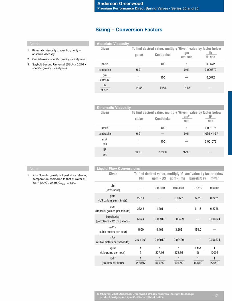
Absolute ViscosityGiven To find desired value, multiply ‘Given’ value by factor below
poise Centipoise gm lbcm–sec ft–sec
poise — 100 1 0.0672
centipoise 0.01 — 0.01 0.000672
gm1 100 — 0.0672
cm–sec
lb—
ft-sec14.88 1488 14.88 —
Kinematic ViscosityGiven To find desired value, multiply ‘Given’ value by factor below
stoke Centistoke cm2 ft2sec sec
stoke — 100 1 0.001076
centistoke 0.01 — 0.01 1.076 x 10⁻⁵
cm21 100 — 0.001076
sec
ft2—
sec929.0 92900 929.0 —
Liquid Flow ConversionsGiven To find desired value, multiply ‘Given’ value by factor below
l/hr gpm - US gpm - Imp barrels/day m3/hr
l/hr — 0.00440 0.003666 0.1510 0.0010
(litres/hour)
gpm(US gallons per minute)
227.1 — 0.8327 34.29 0.2271
gpm272.8 1.201 — 41.18 0.2728
(Imperial gallons per minute)
barrels/day(petroleum - 42 US gallons)
6.624 0.02917 0.02429 — 0.006624
m3/hr 1000 4.403 3.666 151.0 —
(cubic meters per hour)
m3/s(cubic meters per seconds)
3.6 x 10⁶ 0.02917 0.02429 — 0.006624
kg/hr 1 1 1 0.151 1(kilograms per hour) G 227.1G 272.8G G 1000G
lb/hr 1 1 1 1 1(pounds per hour) 2.205G 500.8G 601.5G 14.61G 2205G
Notes
1. Kinematic viscosity x specific gravity = absolute viscosity.
2. Centistokes x specific gravity = centipoise.
3. Saybolt Second Universal (SSU) x 0.216 xspecific gravity = centipoise.
Note
1. G = Specific gravity of liquid at its relieving temperature compared to that of water at68°F [20°C], where Gwater = 1.00.
Sizing – Conversion Factors

Anderson GreenwoodPremium Performance Direct Spring Valves - Series 60 and 80
© 1996/rev. 2000, Anderson Greenwood Crosby reserves the right to change product designs and specifications without notice. 18
Once you have determined the basic type(e.g., 81, 83, etc.) of valve required inStep 1 and determined your required ori-fice area in Step 2, please refer to thefollowing information to finalize the selec-tion and specification and then order thepressure relief valve best suited for yourapplication.
Pressure and Temperature RatingCompare your preliminary selected valvetype and orifice with the following pres-sure and temperature rating tables onpages 19 to 22. This will insure the valvetype and orifice meets the process re-quirements.
Valve MaterialUsing the pressure and temperature rat-ing tables, you can select the proper bodymaterial and soft goods. Keep in mindthat proper selection of soft goods also in-cludes chemical compatibility with theprocess.
Inlet and Outlet - Size and TypePlease refer to the dimensions and weighttables on pages 23 to 34 for proper sizeand type.
Bill of MaterialDetailed bills of material follow on pages35 to 40 to assist finalizing material selec-tion and finally selecting model number.
Ordering – How to Finalize Valve Selection
Anderson GreenwoodPremium Performance Direct Spring Valves - Series 60 and 80
© 1996/rev. 2000, Anderson Greenwood Crosby reserves the right to change product designs and specifications without notice. 19
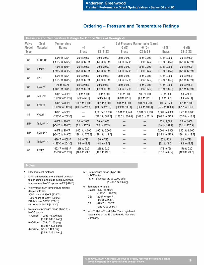
Pressure and Temperature Ratings for Orifice Sizes -4 through -8
Valve Seat Temperature Set Pressure Range, psig [barg]Model Material Range -4 -4 -6 (D) -6 (D) -8 (E) -8 (E)Type Brass CS & SS Brass CS & SS Brass CS & SS
-65°F to 275°F 20 to 2,000 20 to 2,000 20 to 2,000 20 to 2,000 20 to 2,000 20 to 2,00083 BUNA-N1
[-54°C to 135°C] [1.4 to 137.9] [1.4 to 137.9] [1.4 to 137.9] [1.4 to 137.9] [1.4 to 137.9] [1.4 to 137.9]
-40°F to 400°F 20 to 2,000 20 to 2,000 20 to 2,000 20 to 2,000 20 to 2,000 20 to 2,00083 Viton®3
[-40°C to 204°C] [1.4 to 137.9] [1.4 to 137.9] [1.4 to 137.9] [1.4 to 137.9] [1.4 to 137.9] [1.4 to 137.9]
-65°F to 325°F 20 to 2,000 20 to 2,000 20 to 2,000 20 to 2,000 20 to 2,000 20 to 2,00083 EPR
[-54°C to 163°C] [1.4 to 137.9] [1.4 to 137.9] [1.4 to 137.9] [1.4 to 137.9] [1.4 to 137.9] [1.4 to 137.9]
-0°F to 550°F 20 to 2,000 20 to 2,000 20 to 2,000 20 to 2,000 20 to 2,000 20 to 2,00083 Kalrez®
[-18°C to 288°C] [1.4 to 137.9] [1.4 to 137.9] [1.4 to 137.9] [1.4 to 137.9] [1.4 to 137.9] [1.4 to 137.9]
-320°F to 400°F 100 to 1,000 100 to 1,000 100 to 900 100 to 900 50 to 900 50 to 90081 Teflon®1
[-196°C to 204°C] [6.9 to 69.0] [6.9 to 69.0] [6.9 to 62.1] [6.9 to 62.1] [3.4 to 62.1] [3.4 to 62.1]
-320°F to 300°F 1,001 to 4,000 1,001 to 4,000 901 to 1,500 901 to 1,500 901 to 1,500 901 to 1,50081 PCTFE1
[-196°C to 149°C] [69.1 to 275.8] [69.1 to 275.8] [62.2 to 103.4] [62.2 to 103.4] [62.2 to 103.4] [62.2 to 103.4]
-423°F to 500°F — 4,001 to 10,000 1,501 to 4,740 1,501 to 9,600 1,501 to 4,000 1,501 to 6,00081 Vespel1
[-256°C to 260°C] — [276.1 to 689.5] [103.5 to 326.8] [103.5 to 661.9] [103.5 to 275.8] [103.5 to 413.7]
-65°F to 400°F 50 to 2,000 50 to 2,000 — — 50 to 2,000 50 to 2,00081P Teflon®1, 2
[-54°C to 204°C] [3.4 to 137.9] [3.4 to 137.9] — — [3.4 to 137.9] [3.4 to 137.9]
-65°F to 300°F 2,001 to 4,000 2,001 to 6,000 — — 2,001 to 4,000 2,001 to 6,00081P PCTFE1, 2
[-54°C to 149°C] [138.1 to 275.8] [138.1 to 413.7] — — [138.1 to 275.8] [138.1 to 413.7]
-320°F to 400°F 50 to 720 50 to 720 — — 50 to 720 50 to 72086 Teflon®1, 2
[-196°C to 204°C] [3.4 to 49.7] [3.4 to 49.7] — — [3.4 to 49.7] [3.4 to 49.7]
-423°F to 515°F 236 to 720 236 to 720 — — 178 to 720 178 to 72086 PEEK1
[-256°C to 269°C] [16.3 to 49.7] [16.3 to 49.7] — — [12.3 to 49.7] [12.3 to 49.7]
1. Standard seat material.
2. Minimum temperature is based on elas-tomer spindle and guide seals. Minimumtemperature: NACE option: -40°F [-40°C].
3. Viton® maximum temperature ratings(tested with air):3000 hours at 450°F [232°C]1000 hours at 500°F [260°C]240 hours at 550°F [288°C]48 hours at 600°F [316°C].
4. Normal set pressure range (Type 81),NACE option:-4 Orifice: 100 to 10,000 psig
[6.9 to 689.5 barg]-6 Orifice: 100 to 7,100 psig
[6.9 to 489.6 barg]-8 Orifice: 50 to 3,120 psig
[3.5 to 215.1 barg].
5. Set pressure range (Type 83), NACE option:-4, -6, -8 Orifice: 20 to 2,000 psig
[1.4 to 137.9 barg].
6. Temperature range:Brass: -325F to 400°F
[-198°C to 205°C]CS: -20°F to 550°F
[-29°C to 288°C]SS: -423°F to 550°F
[-253°C to 288°C].
7. Viton®, Kalrez® and Teflon® are registeredtrademarks of the E.I. duPont de NemoursCompany.
Notes
Ordering – Pressure and Temperature Ratings
Anderson GreenwoodPremium Performance Direct Spring Valves - Series 60 and 80
© 1996/rev. 2000, Anderson Greenwood Crosby reserves the right to change product designs and specifications without notice. 20
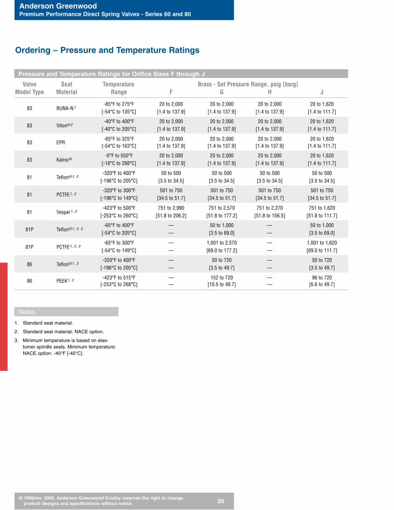
Pressure and Temperature Ratings for Orifice Sizes F through J
Valve Seat Temperature Brass - Set Pressure Range, psig [barg]Model Type Material Range F G H J
-65°F to 275°F 20 to 2,000 20 to 2,000 20 to 2,000 20 to 1,62083 BUNA-N1
[-54°C to 135°C] [1.4 to 137.9] [1.4 to 137.9] [1.4 to 137.9] [1.4 to 111.7]
-40°F to 400°F 20 to 2,000 20 to 2,000 20 to 2,000 20 to 1,62083 Viton®2
[-40°C to 205°C] [1.4 to 137.9] [1.4 to 137.9] [1.4 to 137.9] [1.4 to 111.7]
-65°F to 325°F 20 to 2,000 20 to 2,000 20 to 2,000 20 to 1,62083 EPR
[-54°C to 163°C] [1.4 to 137.9] [1.4 to 137.9] [1.4 to 137.9] [1.4 to 111.7]
-0°F to 550°F 20 to 2,000 20 to 2,000 20 to 2,000 20 to 1,62083 Kalrez®
[-18°C to 288°C] [1.4 to 137.9] [1.4 to 137.9] [1.4 to 137.9] [1.4 to 111.7]
-320°F to 400°F 50 to 500 50 to 500 50 to 500 50 to 50081 Teflon®1, 2
[-196°C to 205°C] [3.5 to 34.5] [3.5 to 34.5] [3.5 to 34.5] [3.5 to 34.5]
-320°F to 300°F 501 to 750 501 to 750 501 to 750 501 to 75081 PCTFE1, 2
[-196°C to 149°C] [34.5 to 51.7] [34.5 to 51.7] [34.5 to 51.7] [34.5 to 51.7]
-423°F to 500°F 751 to 2,990 751 to 2,570 751 to 2,270 751 to 1,62081 Vespel1, 2
[-253°C to 260°C] [51.8 to 206.2] [51.8 to 177.2] [51.8 to 156.5] [51.8 to 111.7]
-65°F to 400°F — 50 to 1,000 — 50 to 1,00081P Teflon®1, 2, 3
[-54°C to 205°C] — [3.5 to 69.0] — [3.5 to 69.0]
-65°F to 300°F — 1,001 to 2,570 — 1,001 to 1,62081P PCTFE1, 2, 3
[-54°C to 149°C] — [69.0 to 177.2] — [69.0 to 111.7]
-320°F to 400°F — 50 to 720 — 50 to 72086 Teflon®1, 2
[-196°C to 205°C] — [3.5 to 49.7] — [3.5 to 49.7]
-423°F to 515°F — 152 to 720 — 96 to 72086 PEEK1, 2
[-253°C to 268°C] — [10.5 to 49.7] — [6.6 to 49.7]
Ordering – Pressure and Temperature Ratings
Notes
1. Standard seat material.
2. Standard seat material: NACE option.
3. Minimum temperature is based on elas-tomer spindle seals. Minimum temperature:NACE option: -40°F [-40°C].

Anderson GreenwoodPremium Performance Direct Spring Valves - Series 60 and 80
© 1996/rev. 2000, Anderson Greenwood Crosby reserves the right to change product designs and specifications without notice. 21
Pressure and Temperature Ratings for Orifice Sizes F through J
Valve Seat Temperature CS and SS - Set Pressure Range, psig [barg]Model Type Material Range F G H J
-65°F to 275°F 20 to 2,000 20 to 2,000 20 to 2,000 20 to 1,62083 BUNA-N1
[-54°C to 135°C] [1.4 to 137.9] [1.4 to 137.9] [1.4 to 137.9] [1.4 to 111.7]
-40°F to 400°F 20 to 2,000 20 to 2,000 20 to 2,000 20 to 2,00083 Viton®2, 4
[-40°C to 205°C] [1.4 to 137.9] [1.4 to 137.9] [1.4 to 137.9] [1.4 to 111.7]
-65°F to 325°F 20 to 2,000 20 to 2,000 20 to 2,000 20 to 1,62083 EPR
[-54°C to 163°C] [1.4 to 137.9] [1.4 to 137.9] [1.4 to 137.9] [1.4 to 111.7]
-0°F to 550°F 20 to 2,000 20 to 2,000 20 to 2,000 20 to 1,62083 Kalrez®
[-18°C to 288°C] [1.4 to 137.9] [1.4 to 137.9] [1.4 to 137.9] [1.4 to 111.7]
-320°F to 400°F 50 to 500 50 to 500 50 to 500 50 to 50081 Teflon®1, 2
[-196°C to 205°C] [3.5 to 34.5] [3.5 to 34.5] [3.5 to 34.5] [3.5 to 34.5]
-320°F to 300°F 501 to 750 501 to 750 501 to 750 501 to 75081 PCTFE1, 2
[-196°C to 149°C] [34.5 to 51.7] [34.5 to 51.7] [34.5 to 51.7] [34.5 to 51.7]
-423°F to 500°F 751 to 4,040 751 to 2,570 751 to 2,580 751 to 1,62081 Vespel1, 2
[-253°C to 260°C] [51.8 to 278.6] [51.8 to 177.2] [51.8 to 177.9] [51.8 to 111.7]
-65°F to 400°F — 50 to 1,000 — 50 to 1,00081P Teflon®1, 2, 3
[-54°C to 205°C] — [3.5 to 69.0] — [3.5 to 69.0]
-65°F to 300°F — 1,001 to 6,000 — 1,001 to 1,62081P PCTFE1, 2, 3
[-54°C to 149°C] — [69.0 to 413.7] — [69.0 to 111.7]
-320°F to 400°F — 50 to 720 — 50 to 72086 Teflon®1, 2
[-196°C to 205°C] — [3.5 to 49.7] — [3.5 to 49.7]
-423°F to 515°F — 152 to 720 — 96 to 72086 PEEK1, 2
[-253°C to 268°C] — [10.5 to 49.7] — [6.6 to 49.7]
Notes
1. Standard seat material.
2. Standard seat material: NACE option.
3. Minimum temperature is based on elas-tomer spindle seals. Minimum temperature:NACE option: -40°F [-40°C].
4. Viton® maximum temperature ratings(tested with air):3000 hours at 450°F [232°C]1000 hours at 500°F [260°C]240 hours at 550°F [288°C]48 hours at 600°F [316°C].
Ordering – Pressure and Temperature Ratings
Anderson GreenwoodPremium Performance Direct Spring Valves - Series 60 and 80
© 1996/rev. 2000, Anderson Greenwood Crosby reserves the right to change product designs and specifications without notice. 22
Pressure and Temperature Ratings
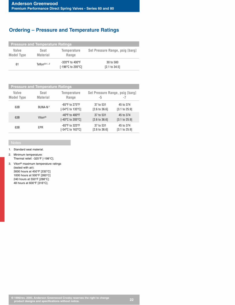
Valve Seat Temperature Set Pressure Range, psig [barg]Model Type Material Range
61 Teflon®1, 2-320°F to 400°F 30 to 500
[-196°C to 205°C] [2.1 to 34.5]
Pressure and Temperature Ratings
Valve Seat Temperature Set Pressure Range, psig [barg]Model Type Material Range -5 -7
-65°F to 275°F 37 to 531 45 to 37463B BUNA-N1
[-54°C to 135°C] [2.6 to 36.6] [3.1 to 25.9]
-40°F to 400°F 37 to 531 45 to 37463B Viton®
[-40°C to 205°C] [2.6 to 36.6] [3.1 to 25.9]
-65°F to 325°F 37 to 531 45 to 37463B EPR
[-54°C to 163°C] [2.6 to 36.6] [3.1 to 25.9]
Notes
1. Standard seat material.
2. Minimum temperature: Thermal relief: -325°F [-198°C].
3. Viton® maximum temperature ratings(tested with air):3000 hours at 450°F [232°C]1000 hours at 500°F [260°C]240 hours at 550°F [288°C]48 hours at 600°F [316°C].
Ordering – Pressure and Temperature Ratings

Anderson GreenwoodPremium Performance Direct Spring Valves - Series 60 and 80
© 1996/rev. 2000, Anderson Greenwood Crosby reserves the right to change product designs and specifications without notice. 23
Dimensions and Weights for -4 Orifice
Valve Body Set Pressure Valve Threaded Dimensions Approx.Model Material Range Connections Connections A B C max2 WeightType Inlet Outlet Inlet Outlet in [mm] in [mm] in [mm] lb [kg]
in [mm] in [mm]
1/2 [15] 3/4 & 1 [18 & 25] FNPT FNPT 2.90 [74] 1.50 [38] 9.55 [243] 4.3 [2.0]1/2 [15] 3/4 & 1 [18 & 25] MNPT FNPT 2.90 [74] 1.50 [38] 9.55 [243] 4.3 [2.0]
81, 83Brass, 20 to 4,000 psig 3/4 [18] 3/4 & 1 [18 & 25] FNPT FNPT 3.07 [78] 1.50 [38] 9.72 [247] 4.3 [2.0]CS, SS [1.4 to 276 barg]1,3
3/4 [18] 3/4 & 1 [18 & 25] MNPT FNPT 2.90 [74] 1.50 [38] 9.55 [243] 4.3 [2.0]1 [25] 1 [25] MNPT FNPT 3.07 [78] 1.50 [38] 9.72 [247] 4.3 [2.0]
4,001 to 10,000 psig 3/4 & 1 [18 & 25] 1 [25] FNPT FNPT 3.70 [94] 1.81 [46] 14.10 [358] 13.3 [6.1]81, 83 CS, SS
[276.1 to 690 barg] 3/4 & 1 [18 & 25] 1 [25] MNPT FNPT 3.80 [97] 1.81 [46] 14.20 [361] 13.3 [6.1]
1/2 [15] 3/4 & 1 [18 & 25] FNPT FNPT 2.90 [74] 1.50 [38] 10.46 [266] 4.5 [2.1]1/2 [15] 3/4 & 1 [18 & 25] MNPT FNPT 2.90 [74] 1.50 [38] 10.46 [266] 4.5 [2.1]
86Brass, 50 to 720 psig 3/4 [18] 3/4 & 1 [18 & 25] FNPT FNPT 3.07 [78] 1.50 [38] 10.63 [270] 4.5 [2.1]CS, SS [3.4 to 49.7 barg] 3/4 [18] 3/4 & 1 [18 & 25] MNPT FNPT 2.90 [74] 1.50 [38] 10.46 [266] 4.5 [2.1]
1 [25] 1 [25] MNPT FNPT 3.07 [78] 1.50 [38] 10.63 [270] 4.5 [2.1]
Brass 50 to 1,160 psig 3/4 & 1 [18 & 25] 1 [25] FNPT FNPT 3.70 [94] 1.81 [46] 10.87 [276] 8.3 [3.8]81P
CS, SS [3.4 to 80 barg] 3/4 & 1 [18 & 25] 1 [25] MNPT FNPT 3.80 [97] 1.81 [46] 10.95 [278] 8.3 [3.8]
81PBrass, 1,161 to 6,000 psig 3/4 & 1 [18 & 25] 1 [25] FNPT FNPT 3.70 [94] 1.81 [46] 14.10 [358.1] 13.8 [6.3]CS, SS [80.1 to 414 barg]4 3/4 & 1 [18 & 25] 1 [25] MNPT FNPT 3.80 [97] 1.81 [46] 14.20 [360.7] 13.8 [6.3]
Notes
1. Normal set pressure range for Type 81: 100 to 4,000 psig [6.9 to 275.8 barg];Type 83: 20 to 2,000 psig [1.4 to 137.9 barg].
2. Add 0.90-inch [23 mm] to ‘C max’ dimension for numbered orifice Type 81, 83, 86and 81P with packed lift lever option.
Maximum set pressure:
3. 3/4-inch MNPT CS and SS Types 81 and 83 is 6,000 psig [413.7 barg].
4. 3/4-inch MNPT Brass Type 81P is 2,120 psig [146.2 barg]
3/4-inch MNPT CS and SS Type 81P is 3,120 psig [215.1 barg]
3/4-inch and 1-inch FNPT Brass Type 81P is 4,000 psig [275.8 barg].
Ordering – Dimensions and Weights
A
C
B
A
C
B
Anderson GreenwoodPremium Performance Direct Spring Valves - Series 60 and 80
© 1996/rev. 2000, Anderson Greenwood Crosby reserves the right to change product designs and specifications without notice. 24
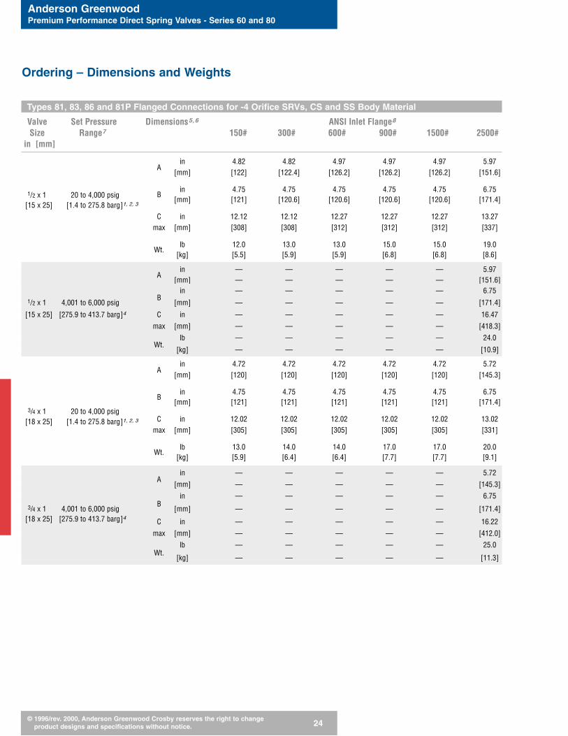
Types 81, 83, 86 and 81P Flanged Connections for -4 Orifice SRVs, CS and SS Body Material
Valve Set Pressure Dimensions5,6 ANSI Inlet Flange8
Size Range7 150# 300# 600# 900# 1500# 2500#in [mm]
in 4.82 4.82 4.97 4.97 4.97 5.97A
[mm] [122] [122.4] [126.2] [126.2] [126.2] [151.6]
1/2 x 1 20 to 4,000 psigin 4.75 4.75 4.75 4.75 4.75 6.75
[15 x 25] [1.4 to 275.8 barg]1, 2, 3
B[mm] [121] [120.6] [120.6] [120.6] [120.6] [171.4]
C in 12.12 12.12 12.27 12.27 12.27 13.27max [mm] [308] [308] [312] [312] [312] [337]
lb 12.0 13.0 13.0 15.0 15.0 19.0Wt.
[kg] [5.5] [5.9] [5.9] [6.8] [6.8] [8.6]
in — — — — — 5.97A
[mm] — — — — — [151.6]in — — — — — 6.75
1/2 x 1 4,001 to 6,000 psigB
[mm] — — — — — [171.4]
[15 x 25] [275.9 to 413.7 barg]4 C in — — — — — 16.47
max [mm] — — — — — [418.3]
lb — — — — — 24.0Wt.
[kg] — — — — — [10.9]
in 4.72 4.72 4.72 4.72 4.72 5.72A
[mm] [120] [120] [120] [120] [120] [145.3]
in 4.75 4.75 4.75 4.75 4.75 6.75
3/4 x 1 20 to 4,000 psig
B[mm] [121] [121] [121] [121] [121] [171.4]
C in 12.02 12.02 12.02 12.02 12.02 13.02[18 x 25] [1.4 to 275.8 barg]1, 2, 3
max [mm] [305] [305] [305] [305] [305] [331]
lb 13.0 14.0 14.0 17.0 17.0 20.0Wt.
[kg] [5.9] [6.4] [6.4] [7.7] [7.7] [9.1]
in — — — — — 5.72A
[mm] — — — — — [145.3]
in — — — — — 6.753/4 x 1 4,001 to 6,000 psig
B[mm] — — — — — [171.4]
[18 x 25] [275.9 to 413.7 barg]4C in — — — — — 16.22
max [mm] — — — — — [412.0]
lb — — — — — 25.0Wt.
[kg] — — — — — [11.3]
Ordering – Dimensions and Weights

Anderson GreenwoodPremium Performance Direct Spring Valves - Series 60 and 80
© 1996/rev. 2000, Anderson Greenwood Crosby reserves the right to change product designs and specifications without notice. 25
Types 81, 83, 86 and 81P Flanged Connections for -4 Orifice SRVs, CS and SS Body Material - continued
Valve Set Pressure Dimensions5,6 ANSI Inlet Flange8
Size Range7 150# 300# 600# 900# 1500# 2500#in [mm]
in 4.72 4.72 4.72 5.72 5.72 5.72A
[mm] [120] [120] [120] [145.3] [145.3] [145.3]
in 4.75 4.75 4.75 6.75 6.75 6.75
1 x 1 20 to 4,000 psigB
[mm] [121] [121] [121] [171.4] [171.4] [171.4]
[25 x 25] [1.4 to 275.8 barg]1, 2, 3 C in 12.02 12.02 12.02 13.02 13.02 13.02max [mm] [305] [305] [305] [331] [331] [331]
lb 13.0 14.0 15.0 20.0 20.0 23.0Wt.
[kg] [5.9] [6.4] [6.8] [9.1] [9.1] [10.5]
in — — — — — 5.72A
[mm] — — — — — [145.3]
in — — — — — 6.75
1 x 1 4,001 to 6,000 psigB
[mm] — — — — — [171.5]
[25 x 25] [275.9 to 413.7 barg]4 C in — — — — — 16.22
max [mm] — — — — — [412.0]
lb — — — — — 28.0Wt.
[kg] — — — — — [12.7]
Ordering – Dimensions and Weights
A
C
B
A
C
B
Notes
1. Normal set pressure range for Type 81: 100 to 4,000 psig [6.9 to 275.8 barg].
2. Set pressure range for Type 86: 50 to 720 psig [3.5 to 49.6 barg].
3. Set pressure range for Type 81P: 50 to 1,160 psig [3.5 to 80.0 barg].
4. Set pressure range for Type 81P: 1,161 to 6,000 psig [80.1 to 413.7 barg].
5. Add 0.90-inch [23 mm] to ‘C max’ dimension for numbered orifice Types 81,83, 86 and 81P with packed lift lever option.
6. Dimensions listed are for the connection sizes illustrated only, with slip-onflanges. For other connection sizes and types, or for weld neck flanges, con-sult factory for dimensions.
7. Maximum set pressure values shown for MNPT and flanged SRVs are forvalves without thrust load bracing, i.e. valves discharging directly to atmos-phere or through a tailpipe without adequate piping support. For subject valvesdischarging to properly supported outlet piping, or to a suitable discharge pipeconfiguration, the maximum set pressure values will be higher. Please consultfactory for details.
8. Dimensions do not vary with outlet flange ratings.

Anderson GreenwoodPremium Performance Direct Spring Valves - Series 60 and 80
© 1996/rev. 2000, Anderson Greenwood Crosby reserves the right to change product designs and specifications without notice. 26
Dimensions and Weights for -6 (D) Orifice
Valve Body Set Pressure Valve Threaded Dimensions Approx.Model Material Range4 Connections Connections A B C max2 WeightType Inlet Outlet Inlet Outlet in [mm] in [mm] in [mm] lb [kg]
in [mm] in [mm]
81, 83Brass 20 to 1,410 psig 1/2, 3/4 &1 [15, 18 & 25] 1 [25] FNPT FNPT 3.70 [94] 1.81 [46] 10.99 [279] 8.3 [3.8]
CS, SS [1.4 to 97.2 barg]1 3/4 &1 [18 &25] 1 [25] MNPT FNPT 3.80 [97] 1.81 [46] 10.99 [279] 8.3 [3.8]
Brass 1,411 to 9,600 psig 1/2, 3/4 &1 [15, 18 & 25] 1 [25] FNPT FNPT 3.70 [94] 1.81 [46] 14.18 [360] 13.3 [6.0]81, 83
CS, SS [97.3 to 662 barg]1,3 3/4 &1 [18 & 25] 1 [25] MNPT FNPT 3.80 [97] 1.81 [46] 14.20 [361] 13.3 [6.0]
Notes
1. Normal set pressure range for Type 81: 100 to 1,410 psig [6.9 to 97.2 barg]
2. Add 0.90-inch [23 mm] to ‘C max’ dimension for numbered orifice Types 81 and 83 with packedlift lever option.
3. Maximum set pressure:3/4-inch [18 mm] MNPT Brass Types 81 and 83 is 2,110 psig [145.5 barg]
1-inch [25 mm] MNPT Brass Types 81 and 83 is 3,140 psig [216.5 barg]
3/4-inch [18 mm] MNPT CS and SS Types 81 and 83 is 3,140 psig [216.5 barg]
1-inch [25 mm] MNPT CS and SS Types 81 and 83 is 6,000 psig [413.7 barg]
1/2-inch, 3/4-inch, 1-inch [15, 18, 25 mm] FNPT Brass Types 81 and 83 is 4,740 psig [326.8 barg].
4. Maximum set pressure values shown for MNPT and flanged SRVs are for valves without thrustload bracing, i.e. valves discharging directly to atmosphere or through a tailpipe without adequatepiping support. For subject valves discharging to properly supported outlet piping, or to a suitabledischarge pipe configuration, the maximum set pressure values will be higher.
Ordering – Dimensions and Weights
A
C
B
A
C
B

Anderson GreenwoodPremium Performance Direct Spring Valves - Series 60 and 80
© 1996/rev. 2000, Anderson Greenwood Crosby reserves the right to change product designs and specifications without notice. 27
Types 81 and 83 Flanged Connections for -6 (D) Orifice SRVs, CS and SS Body Material (continued on page 28)
Valve Set Pressure Dimensions2,3 ANSI Inlet Flange5
Size Range4 150# 300# 600# 900# 1500# 2500#in [mm]
in 4.82 4.82 4.97 4.97 4.97 5.97A
[mm] [122] [122] [126] [126] [126] [152]
in 4.75 4.75 4.75 4.75 4.75 6.75
1/2 x 1 20 to 1,410 psigB
[mm] [121] [121] [121] [121] [121] [172]
[15 x 25] [1.4 to 97.2 barg]1 C in 12.12 12.12 12.27 12.27 12.27 13.27max [mm] [308] [308] [312] [312] [312] [337]
lb 12.0 13.0 13.0 15.0 15.0 19.0Wt.
[kg] [5.4] [5.9] [5.9] [6.8] [6.8] [8.6]
in — — 4.97 4.97 4.97 5.97A
[mm] — — [126] [126] [126] [152]
in — — 4.75 4.75 4.75 6.751/2 x 1 1,411 to 3,141 psig
B[mm] — — [121] [121] [121] [172]
[15 x 25] [97.3 to 217 barg] C in — — 15.47 15.47 15.47 16.47
max [mm] — — [393] [393] [393] [418]
lb — — 18.0 20.0 20.0 24.0Wt.
[kg] — — [8.2] [9.1] [9.1] [10.9]
in 4.72 4.72 4.72 4.72 4.72 5.72A
[mm] [120] [120] [120] [120] [120] [145]
in 4.75 4.75 4.75 4.75 4.75 6.753/4 x 1 20 to 1,410 psig
B[mm] [121] [121] [121] [121] [121] [172]
[18 x 25] [1.4 to 97.2 barg]1C in 12.02 12.02 12.02 12.02 12.02 13.02
max [mm] [305] [305] [305] [305] [305] [331]
lb 13.0 14.0 14.0 17.0 17.0 20.0Wt.
[kg] [5.9] [6.4] [6.4] [7.7] [7.7] [9.1]
in — — 4.72 4.72 4.72 5.72A
[mm] — — [120] [120] [120] [145]
in — — 4.75 4.75 4.75 6.753/4 x 1 1,411 to 3,141 psig
B[mm] — — [121] [121] [121] [172]
[18 x 25] [97.3 to 217 barg] C in — — 15.22 15.22 15.22 16.22
max [mm] — — [387] [387] [387] [387]
lb — — 19.0 22.0 22.0 25.0Wt.
[kg] — — [8.6] [10.0] [10.0] [11.3]
Ordering – Dimensions and Weights
Notes
1. Normal set pressure range for Type 81: 100 to 1,410 psig [6.9 to 97 barg].
2. Add 0.90-inch [23 mm] to ‘C max’ dimension for numbered orifice Types 81and 83 with packed liftlever option.
3. Dimensions listed are for the connection sizes illustrated only, with slip-on flanges. For other connec-tion sizes and types, or for weld neck flanges, consult factory for dimensions.
4. Maximum set pressure values shown for MNPT and flanged SRVs are for valves without thrust loadbracing, i.e. valves discharging directly to atmosphere or through a tailpipe without adequate pipingsupport. For subject valves discharging to properly supported outlet piping, or to a suitable dischargepipe configuration, the maximum set pressure values will be higher. Please consult factory for details.
5. Dimensions do not vary with outlet flange pressure rating.
A
C
B
A
C
B

Anderson GreenwoodPremium Performance Direct Spring Valves - Series 60 and 80
© 1996/rev. 2000, Anderson Greenwood Crosby reserves the right to change product designs and specifications without notice. 28
Types 81 and 83 Flanged Connections for -6 (D) Orifice SRVs, CS and SS Body Material - continued
Valve Set Pressure Dimensions2,3 ANSI Inlet Flange5
Size Range4 150# 300# 600# 900# 1500# 2500#in [mm]
in 4.72 4.72 4.72 5.72 5.72 5.72A
[mm] [120] [120] [120] [145] [145] [145]
in 4.75 4.75 4.75 6.75 6.75 6.75
1 x 1 20 to 1,410 psigB
[mm] [121] [121] [121] [172] [172] [172]
[25 x 25] [1.4 to 97.2 barg]1C in 12.02 12.02 12.02 13.02 13.02 13.02
max [mm] [305] [305] [305] [331] [331] [331]
lb 13.0 14.0 15.0 20.0 20.0 23.0Wt.
[kg] [5.9] [6.4] [6.8] [9.1] [9.1] [10.5]
in — — 4.72 5.72 5.72 5.72A
[mm] — — [120] [145] [145] [145]
in — — 4.75 6.75 6.75 6.751 x 1 1,411 to 3,141 psig B
[mm] — — [121] [172] [172] [172][25 x 25] [97.3 to 217 barg]
C in — — 15.22 16.22 16.22 16.22
max [mm] — — [387] [412] [412] [412]
lb — — 20.0 25.0 25.0 28.0Wt.
[kg] — — [9.1] [11.4] [11.4] [12.7]
Ordering – Dimensions and Weights
A
C
B
A
C
B
Notes
1. Normal set pressure range for Type 81: 100 to 1,410 psig [6.9 to 97 barg].
2. Add 0.90-inch [23 mm] to ‘C max’ dimension for numbered orifice Types 81 and 83 with packed liftlever option.
3. Dimensions listed are for the connection sizes illustrated only, with slip-on flanges. For other connec-tion sizes and types, or for weld neck flanges, consult factory for dimensions.
4. Maximum set pressure values shown for MNPT and flanged SRVs are for valves without thrust loadbracing, i.e. valves discharging directly to atmosphere or through a tailpipe without adequate pipingsupport. For subject valves discharging to properly supported outlet piping, or to a suitable dischargepipe configuration, the maximum set pressure values will be higher. Please consult factory for details.
5. Dimensions do not vary with outlet flange pressure rating.

Anderson GreenwoodPremium Performance Direct Spring Valves - Series 60 and 80
© 1996/rev. 2000, Anderson Greenwood Crosby reserves the right to change product designs and specifications without notice. 29
Dimensions and Weights for -8 (E) Orifice
Valve Body Set Pressure Valve Threaded Dimensions Approx.Model Material Range6 Connections Connections A B C max2 WeightType Inlet Outlet Inlet Outlet in [mm] in [mm] in [mm] lb [kg]
in [mm] in [mm]
Brass 20 to 600 psig 3/4 & 1 [18 & 25] 1 [25] FNPT FNPT 3.70 [94] 1.81 [46.0] 10.99 [279] 8.3 [3.8]81, 83
CS, SS [1.4 to 41.4 barg]1 3/4 & 1 [18 & 25] 1 [25] MNPT FNPT 3.80 [97] 1.81 [46.0] 10.99 [279] 8.3 [3.8]
Brass 601 to 4,000 psig 3/4 & 1 [18 & 25] 1 [25] FNPT FNPT 3.70 [94] 1.81 [46.0] 14.10 [358] 13.8 [6.3]81, 83
CS, SS [41.5 to 276 barg]3 3/4 & 1 [18 & 25] 1 [25] MNPT FNPT 3.80 [97] 1.81 [46.0] 14.20 [361] 13.8 [6.3]
Brass 50 to 600 psig 3/4 & 1 [18 & 25] 1 [25] FNPT FNPT 3.70 [94] 1.81 [46.0] 10.87 [276] 8.5 [3.9]86
CS, SS [3.4 to 41.4 barg] 3/4 & 1 [18 & 25] 1 [25] MNPT FNPT 3.80 [97] 1.81 [46.0] 10.95 [278] 8.5 [3.9]
Brass 601 to 720 psig 3/4 & 1 [18 & 25] 1 [25] FNPT FNPT 3.70 [94] 1.81 [46.0] 14.10 [358] 14.0 [6.4]86
CS, SS [41.5 to 49.7 barg] 3/4 & 1 [18 & 25] 1 [25] MNPT FNPT 3.80 [97] 1.81 [46.0] 14.20 [361] 14.0 [6.4]
Brass 50 to 600 psig 3/4 & 1 [18 & 25] 1 [25] FNPT FNPT 3.70 [94] 1.81 [46.0] 10.81 [275] 8.3 [3.8]81P
CS, SS [3.4 to 41.4 barg]4 3/4 & 1 [18 & 25] 1 [25] MNPT FNPT 3.80 [97] 1.81 [46.0] 10.95 [278] 8.3 [3.8]
Brass 601 to 4,000 psig 3/4 & 1 [18 & 25] 1 [25] FNPT FNPT 3.70 [94] 1.81 [46.0] 14.10 [358] 13.8 [6.3]81P
CS, SS [41.5 to 276 barg]5 3/4 & 1 [18 & 25] 1 [25] MNPT FNPT 3.80 [97] 1.81 [46.0] 14.20 [361] 13.8 [6.3]
81, 81P CS, SS4,001 to 6,000 psig
11/2 [40] 2 [50] FNPT FNPT 3.41 [87] 3.50 [89] 19.60 [498] 25.0 [11.4][276.1 to 414 barg]
1. Normal set pressure range for Type 81: 50to 600 psig [3.5 to 41.4 barg].
2. Add 0.90-inch [23 mm] to ‘C max’ dimensionfor numbered orifice Types 81, 83, 86 and81P with packed lift lever option.
Add 2.0-inch [102 mm] to ‘C max’ dimen-sion for Type 81-E orifice with set pressurerange 4,001 to 6,000 psig [276 to 414 barg]with packed lift lever option.
Add 1.75-inch [45 mm] to ‘C max’ dimen-sion for Type 81P-E orifice with setpressure range 4,001 to 6,000 psig [276 to414 barg] with packed lift lever option.
3. Maximum set pressure:
3/4-inch [18 mm] MNPT Brass Types 81 and83 is 900 psig [62 barg]
1-inch [25 mm] MNPT Brass Types 81 and83 is 2,120 psig [146 barg]
3/4-inch [18 mm] MNPT CS and SS Types 81 and 83 is 1,340 psig [92.4 barg]
1-inch [25 mm] MNPT CS and SS Types 81and 83 is 3,120 psig [215 barg].
4. 3/4-inch [18 mm] MNPT Brass Type 81P is600 psig [41.4 barg].
5. 1-inch [25 mm] MNPT Brass Type 81P is2,120 psig [146 barg]
3/4-inch [18 mm] MNPT CS and SS Type81P is 900 psig [62 barg]
1-inch [25 mm] MNPT CS and SS Type 81Pis 3,120 psig [215 barg].
6. Maximum set pressure values shown forMNPT and flanged SRVs are for valveswithout thrust load bracing, i.e. valves dis-charging directly to atmosphere or througha tailpipe without adequate piping support.For subject valves discharging to properlysupported outlet piping, or to a suitable dis-charge pipe configuration, the maximum setpressure values will be higher. Please con-sult factory for details.
Notes
Ordering – Dimensions and Weights
A
C
B
A
C
B
Anderson GreenwoodPremium Performance Direct Spring Valves - Series 60 and 80
© 1996/rev. 2000, Anderson Greenwood Crosby reserves the right to change product designs and specifications without notice. 30
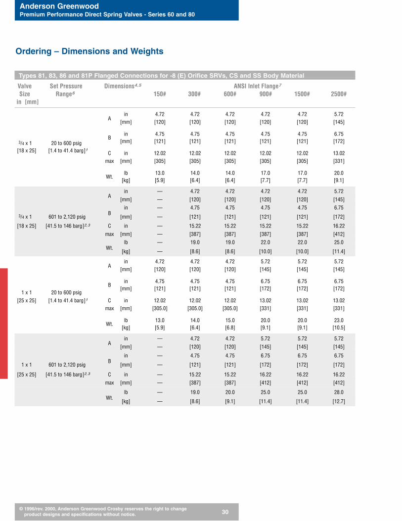
Types 81, 83, 86 and 81P Flanged Connections for -8 (E) Orifice SRVs, CS and SS Body Material
Valve Set Pressure Dimensions4,5 ANSI Inlet Flange7
Size Range6 150# 300# 600# 900# 1500# 2500#in [mm]
in 4.72 4.72 4.72 4.72 4.72 5.72A
[mm] [120] [120] [120] [120] [120] [145]
in 4.75 4.75 4.75 4.75 4.75 6.753/4 x 1 20 to 600 psig
B[mm] [121] [121] [121] [121] [121] [172]
[18 x 25] [1.4 to 41.4 barg]1C in 12.02 12.02 12.02 12.02 12.02 13.02
max [mm] [305] [305] [305] [305] [305] [331]
lb 13.0 14.0 14.0 17.0 17.0 20.0Wt.
[kg] [5.9] [6.4] [6.4] [7.7] [7.7] [9.1]
in — 4.72 4.72 4.72 4.72 5.72A
[mm] — [120] [120] [120] [120] [145]
in — 4.75 4.75 4.75 4.75 6.753/4 x 1 601 to 2,120 psig
B[mm] — [121] [121] [121] [121] [172]
[18 x 25] [41.5 to 146 barg]2,3 C in — 15.22 15.22 15.22 15.22 16.22
max [mm] — [387] [387] [387] [387] [412]
lb — 19.0 19.0 22.0 22.0 25.0Wt.
[kg] — [8.6] [8.6] [10.0] [10.0] [11.4]
in 4.72 4.72 4.72 5.72 5.72 5.72A
[mm] [120] [120] [120] [145] [145] [145]
in 4.75 4.75 4.75 6.75 6.75 6.75
1 x 1 20 to 600 psigB
[mm] [121] [121] [121] [172] [172] [172]
[25 x 25] [1.4 to 41.4 barg]1 C in 12.02 12.02 12.02 13.02 13.02 13.02max [mm] [305.0] [305.0] [305.0] [331] [331] [331]
lb 13.0 14.0 15.0 20.0 20.0 23.0Wt.
[kg] [5.9] [6.4] [6.8] [9.1] [9.1] [10.5]
in — 4.72 4.72 5.72 5.72 5.72A
[mm] — [120] [120] [145] [145] [145]
in — 4.75 4.75 6.75 6.75 6.75
1 x 1 601 to 2,120 psigB
[mm] — [121] [121] [172] [172] [172]
[25 x 25] [41.5 to 146 barg]2,3 C in — 15.22 15.22 16.22 16.22 16.22
max [mm] — [387] [387] [412] [412] [412]
lb — 19.0 20.0 25.0 25.0 28.0Wt.
[kg] — [8.6] [9.1] [11.4] [11.4] [12.7]
Ordering – Dimensions and Weights

Anderson GreenwoodPremium Performance Direct Spring Valves - Series 60 and 80
© 1996/rev. 2000, Anderson Greenwood Crosby reserves the right to change product designs and specifications without notice. 31
Ordering – Dimensions and Weights
Types 81, 83, 86 and 81P Flanged Connections for -8 (E) Orifice SRVs, CS and SS Body Material - continued
Valve Set Pressure Dimensions4,5 ANSI Inlet Flange7
Size Range6 150# 300# 600# 900# 1500# 2500#in [mm]
in 4.72 4.72 4.72 5.72 5.72 5.72A
[mm] [120] [120] [120] [145] [145] [145]
in 4.75 4.75 4.75 6.75 6.75 6.75
1 x 2 20 to 600 psigB
[mm] [121] [121] [121] [172] [172] [172]
[25 x 50] [1.4 to 41.4 barg]1 C in 12.02 12.02 12.02 13.02 13.02 13.02max [mm] [305] [305] [305] [331] [331] [331]
lb 16.0 17.0 18.0 25.0 25.0 28.0Wt.
[kg] [7.3] [7.7] [8.2] [11.4] [11.4] [12.7]
in — 4.72 4.72 5.72 5.72 5.72A
[mm] — [120] [120] [145] [145] [145]
in — 4.75 4.75 6.75 6.75 6.75
1 x 2 601 to 2,120 psigB
[mm] — [121] [121] [172] [172] [172]
[25 x 50] [41.1 to 146 barg]2,3 C in — 15.22 15.22 16.22 16.22 16.22
max [mm] — [387] [387] [412] [412] [412]
lb — 22.0 23.0 30.0 30.0 33.0Wt.
[kg] — [10] [10.5] [13.6] [13.6] [15]
A
C
B
A
C
B
Notes
1. Normal set pressure range for Types 81, 86 and 81P: 50 to 600 psig [3.5 to 41.4 barg].
2. Set pressure range for Type 86: 601 to 720 psig [41.4 to 49.6 barg].
3. Set pressure range for Type 81P: 601 to 1,340 psig [41.4 to 92 barg].
4. Add 0.90-inch [23 mm] to ‘C max’ dimension for numbered orifice Types 81, 83, 86 and 81Pwith packed lift lever option.
5. Dimensions listed are for the connection sizes illustrated only, with slip-on flanges. Forother connection sizes, or for weld neck flanges, consult factory for dimensions.
6. Maximum set pressure values shown for MNPT and flanged SRVs are for valves withoutthrust load bracing, i.e. valves discharging directly to atmosphere or through a tailpipe with-out adequate piping support. For subject valves discharging to properly supported outletpiping, or to a suitable discharge pipe configuration, the maximum set pressure values willbe higher. Please consult factory for details.
7. Dimensions do not vary with outlet flange pressure rating.
Anderson GreenwoodPremium Performance Direct Spring Valves - Series 60 and 80
© 1996/rev. 2000, Anderson Greenwood Crosby reserves the right to change product designs and specifications without notice. 32
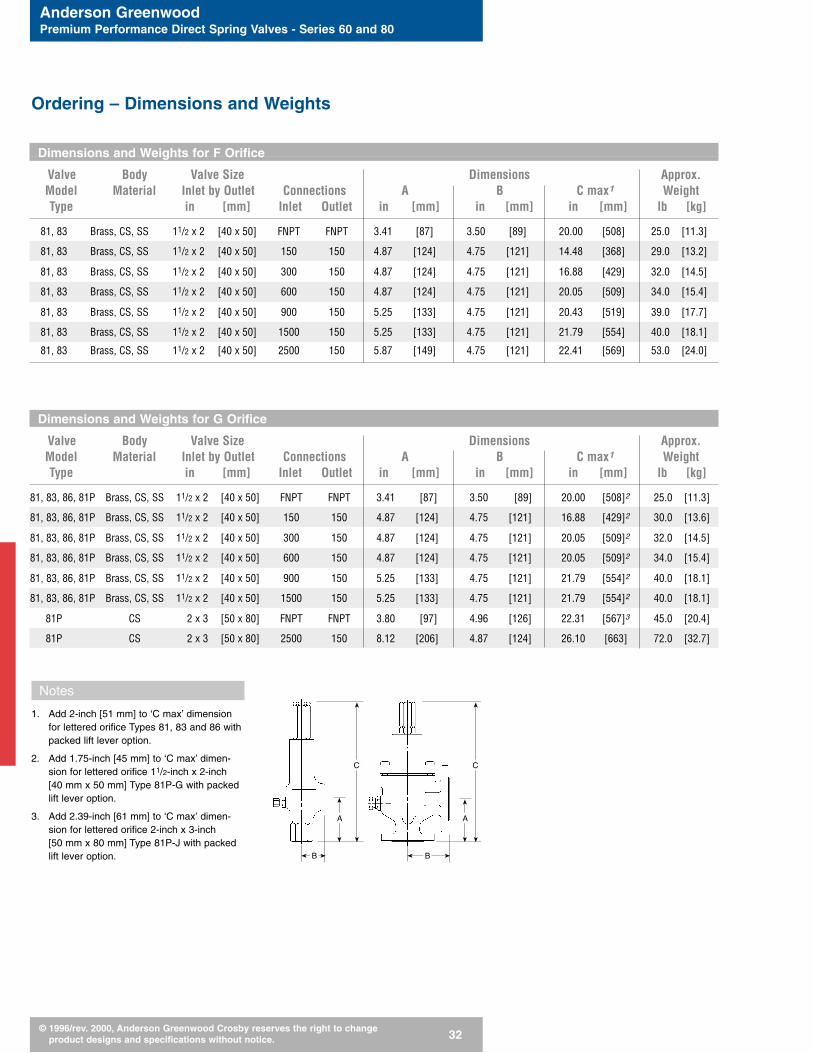
Dimensions and Weights for F Orifice
Valve Body Valve Size Dimensions Approx.Model Material Inlet by Outlet Connections A B C max1 WeightType in [mm] Inlet Outlet in [mm] in [mm] in [mm] lb [kg]
81, 83 Brass, CS, SS 11/2 x 2 [40 x 50] FNPT FNPT 3.41 [87] 3.50 [89] 20.00 [508] 25.0 [11.3]
81, 83 Brass, CS, SS 11/2 x 2 [40 x 50] 150 150 4.87 [124] 4.75 [121] 14.48 [368] 29.0 [13.2]
81, 83 Brass, CS, SS 11/2 x 2 [40 x 50] 300 150 4.87 [124] 4.75 [121] 16.88 [429] 32.0 [14.5]
81, 83 Brass, CS, SS 11/2 x 2 [40 x 50] 600 150 4.87 [124] 4.75 [121] 20.05 [509] 34.0 [15.4]
81, 83 Brass, CS, SS 11/2 x 2 [40 x 50] 900 150 5.25 [133] 4.75 [121] 20.43 [519] 39.0 [17.7]
81, 83 Brass, CS, SS 11/2 x 2 [40 x 50] 1500 150 5.25 [133] 4.75 [121] 21.79 [554] 40.0 [18.1]
81, 83 Brass, CS, SS 11/2 x 2 [40 x 50] 2500 150 5.87 [149] 4.75 [121] 22.41 [569] 53.0 [24.0]
Dimensions and Weights for G Orifice
Valve Body Valve Size Dimensions Approx.Model Material Inlet by Outlet Connections A B C max1 WeightType in [mm] Inlet Outlet in [mm] in [mm] in [mm] lb [kg]
81, 83, 86, 81P Brass, CS, SS 11/2 x 2 [40 x 50] FNPT FNPT 3.41 [87] 3.50 [89] 20.00 [508]2 25.0 [11.3]
81, 83, 86, 81P Brass, CS, SS 11/2 x 2 [40 x 50] 150 150 4.87 [124] 4.75 [121] 16.88 [429]2 30.0 [13.6]
81, 83, 86, 81P Brass, CS, SS 11/2 x 2 [40 x 50] 300 150 4.87 [124] 4.75 [121] 20.05 [509]2 32.0 [14.5]
81, 83, 86, 81P Brass, CS, SS 11/2 x 2 [40 x 50] 600 150 4.87 [124] 4.75 [121] 20.05 [509]2 34.0 [15.4]
81, 83, 86, 81P Brass, CS, SS 11/2 x 2 [40 x 50] 900 150 5.25 [133] 4.75 [121] 21.79 [554]2 40.0 [18.1]
81, 83, 86, 81P Brass, CS, SS 11/2 x 2 [40 x 50] 1500 150 5.25 [133] 4.75 [121] 21.79 [554]2 40.0 [18.1]
81P CS 2 x 3 [50 x 80] FNPT FNPT 3.80 [97] 4.96 [126] 22.31 [567]3 45.0 [20.4]
81P CS 2 x 3 [50 x 80] 2500 150 8.12 [206] 4.87 [124] 26.10 [663] 72.0 [32.7]
Notes
1. Add 2-inch [51 mm] to ‘C max’ dimensionfor lettered orifice Types 81, 83 and 86 withpacked lift lever option.
2. Add 1.75-inch [45 mm] to ‘C max’ dimen-sion for lettered orifice 11/2-inch x 2-inch [40 mm x 50 mm] Type 81P-G with packedlift lever option.
3. Add 2.39-inch [61 mm] to ‘C max’ dimen-sion for lettered orifice 2-inch x 3-inch [50 mm x 80 mm] Type 81P-J with packedlift lever option.
Ordering – Dimensions and Weights
A
C
B
A
C
B
Anderson GreenwoodPremium Performance Direct Spring Valves - Series 60 and 80
© 1996/rev. 2000, Anderson Greenwood Crosby reserves the right to change product designs and specifications without notice. 33
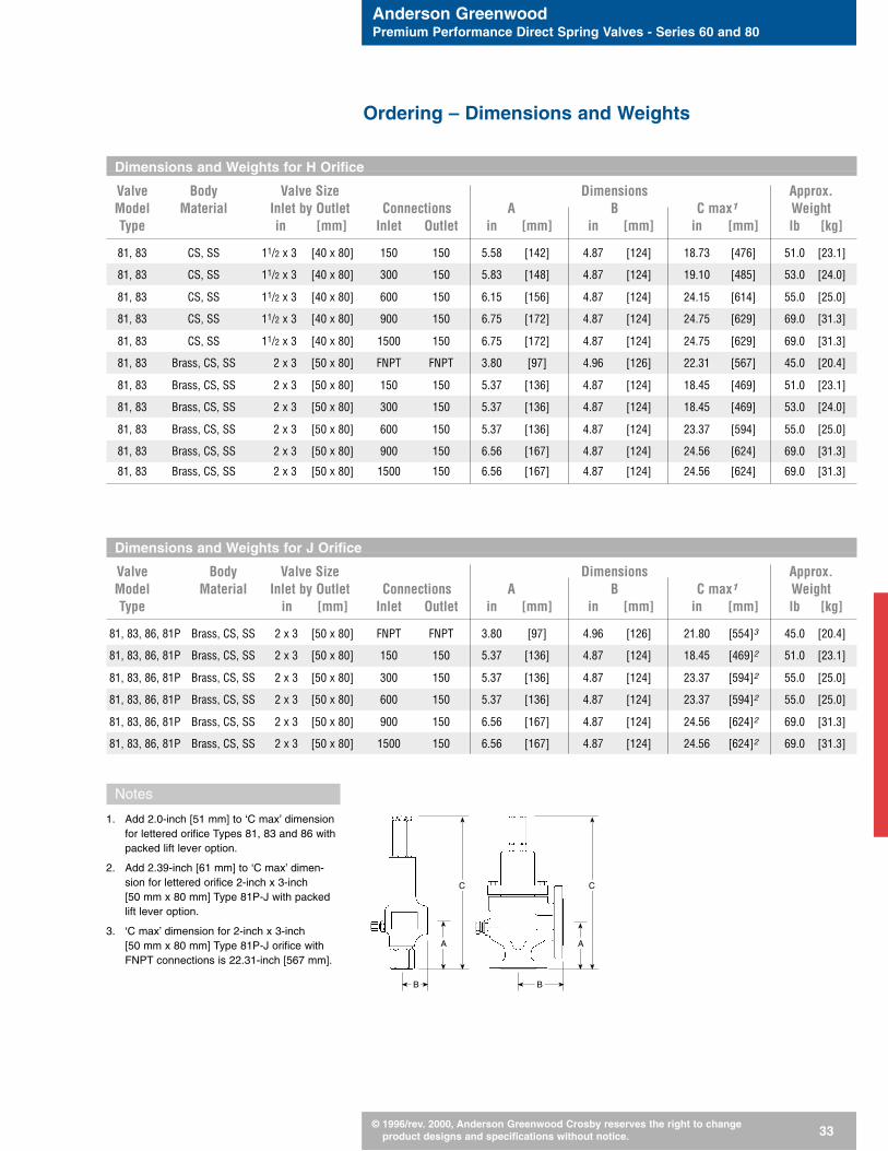
Dimensions and Weights for H Orifice
Valve Body Valve Size Dimensions Approx.Model Material Inlet by Outlet Connections A B C max1 WeightType in [mm] Inlet Outlet in [mm] in [mm] in [mm] lb [kg]
81, 83 CS, SS 11/2 x 3 [40 x 80] 150 150 5.58 [142] 4.87 [124] 18.73 [476] 51.0 [23.1]
81, 83 CS, SS 11/2 x 3 [40 x 80] 300 150 5.83 [148] 4.87 [124] 19.10 [485] 53.0 [24.0]
81, 83 CS, SS 11/2 x 3 [40 x 80] 600 150 6.15 [156] 4.87 [124] 24.15 [614] 55.0 [25.0]
81, 83 CS, SS 11/2 x 3 [40 x 80] 900 150 6.75 [172] 4.87 [124] 24.75 [629] 69.0 [31.3]
81, 83 CS, SS 11/2 x 3 [40 x 80] 1500 150 6.75 [172] 4.87 [124] 24.75 [629] 69.0 [31.3]
81, 83 Brass, CS, SS 2 x 3 [50 x 80] FNPT FNPT 3.80 [97] 4.96 [126] 22.31 [567] 45.0 [20.4]
81, 83 Brass, CS, SS 2 x 3 [50 x 80] 150 150 5.37 [136] 4.87 [124] 18.45 [469] 51.0 [23.1]
81, 83 Brass, CS, SS 2 x 3 [50 x 80] 300 150 5.37 [136] 4.87 [124] 18.45 [469] 53.0 [24.0]
81, 83 Brass, CS, SS 2 x 3 [50 x 80] 600 150 5.37 [136] 4.87 [124] 23.37 [594] 55.0 [25.0]
81, 83 Brass, CS, SS 2 x 3 [50 x 80] 900 150 6.56 [167] 4.87 [124] 24.56 [624] 69.0 [31.3]
81, 83 Brass, CS, SS 2 x 3 [50 x 80] 1500 150 6.56 [167] 4.87 [124] 24.56 [624] 69.0 [31.3]
Dimensions and Weights for J Orifice
Valve Body Valve Size Dimensions Approx.Model Material Inlet by Outlet Connections A B C max1 WeightType in [mm] Inlet Outlet in [mm] in [mm] in [mm] lb [kg]
81, 83, 86, 81P Brass, CS, SS 2 x 3 [50 x 80] FNPT FNPT 3.80 [97] 4.96 [126] 21.80 [554]3 45.0 [20.4]
81, 83, 86, 81P Brass, CS, SS 2 x 3 [50 x 80] 150 150 5.37 [136] 4.87 [124] 18.45 [469]2 51.0 [23.1]
81, 83, 86, 81P Brass, CS, SS 2 x 3 [50 x 80] 300 150 5.37 [136] 4.87 [124] 23.37 [594]2 55.0 [25.0]
81, 83, 86, 81P Brass, CS, SS 2 x 3 [50 x 80] 600 150 5.37 [136] 4.87 [124] 23.37 [594]2 55.0 [25.0]
81, 83, 86, 81P Brass, CS, SS 2 x 3 [50 x 80] 900 150 6.56 [167] 4.87 [124] 24.56 [624]2 69.0 [31.3]
81, 83, 86, 81P Brass, CS, SS 2 x 3 [50 x 80] 1500 150 6.56 [167] 4.87 [124] 24.56 [624]2 69.0 [31.3]
Notes
1. Add 2.0-inch [51 mm] to ‘C max’ dimensionfor lettered orifice Types 81, 83 and 86 withpacked lift lever option.
2. Add 2.39-inch [61 mm] to ‘C max’ dimen-sion for lettered orifice 2-inch x 3-inch [50 mm x 80 mm] Type 81P-J with packedlift lever option.
3. ‘C max’ dimension for 2-inch x 3-inch [50 mm x 80 mm] Type 81P-J orifice withFNPT connections is 22.31-inch [567 mm].
Ordering – Dimensions and Weights
A
C
B
A
C
B
Anderson GreenwoodPremium Performance Direct Spring Valves - Series 60 and 80
© 1996/rev. 2000, Anderson Greenwood Crosby reserves the right to change product designs and specifications without notice. 34
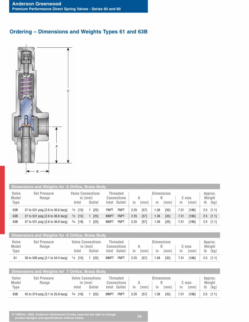
Dimensions and Weights for -5 Orifice, Brass Body
Valve Set Pressure Valve Connections Threaded Dimensions Approx.Model Range in [mm] Connections A B C max WeightType Inlet Outlet Inlet Outlet in [mm] in [mm] in [mm] lb [kg]
63B 37 to 531 psig [2.6 to 36.6 barg] 1/2 [15] 1 [25] FNPT FNPT 2.25 [57] 1.38 [35] 7.31 [186] 2.5 [1.1]
63B 37 to 531 psig [2.6 to 36.6 barg] 1/2 [15] 1 [25] MNPT FNPT 2.25 [57] 1.38 [35] 7.31 [186] 2.5 [1.1]
63B 37 to 531 psig [2.6 to 36.6 barg] 3/4 [18] 1 [25] MNPT FNPT 2.25 [57] 1.38 [35] 7.31 [186] 2.5 [1.1]
Dimensions and Weights for -6 Orifice, Brass Body
Valve Set Pressure Valve Connections Threaded Dimensions Approx.Model Range in [mm] Connections A B C max WeightType Inlet Outlet Inlet Outlet in [mm] in [mm] in [mm] lb [kg]
61 30 to 500 psig [2.1 to 34.5 barg] 1/2 [15] 1 [25] MNPT FNPT 2.25 [57] 1.38 [35] 7.31 [186] 2.5 [1.1]
Dimensions and Weights for 7 Orifice, Brass Body
Valve Set Pressure Valve Connections Threaded Dimensions Approx.Model Range in [mm] Connections A B C max WeightType Inlet Outlet Inlet Outlet in [mm] in [mm] in [mm] lb [kg]
63B 45 to 374 psig [3.1 to 25.8 barg] 3/4 [18] 1 [25] MNPT FNPT 2.25 [57] 1.38 [35] 7.31 [186] 2.5 [1.1]
Ordering – Dimensions and Weights Types 61 and 63B
C
A
B

Anderson GreenwoodPremium Performance Direct Spring Valves - Series 60 and 80
© 1996/rev. 2000, Anderson Greenwood Crosby reserves the right to change product designs and specifications without notice. 35
1
2
4
5
9
8
7
3
10
6
11
Ordering – Types 61 and 63B Materials of Construction
Type 63B
Type 61
Standard Materials
Item No. Part Name Material
1 Body BRS SB62
2 Spring Washer A582 303 SS
3 Spring 316 SS or 17-7 PH SS
A582 303 SS (Type 63B)4 Spindle
BRS B16
5 SeatBUNA-N1, Viton®, EPR (Type 63B)PTFE1 (Type 61)
6 Nozzle BRS B16
7 Lock Nut Brass
8 Pressure Adjustment Screw A108 12214 CS
9 Cap BRS B16
316 SS (Type 63B)10 Seat Retainer Screw
17-4 PH SS (Type 61)
11 Seat Retainer A581 303 SS (Type 63B)
Note
1. Standard seat material.
4
5
10
6
Anderson GreenwoodPremium Performance Direct Spring Valves - Series 60 and 80
© 1996/rev. 2000, Anderson Greenwood Crosby reserves the right to change product designs and specifications without notice. 36
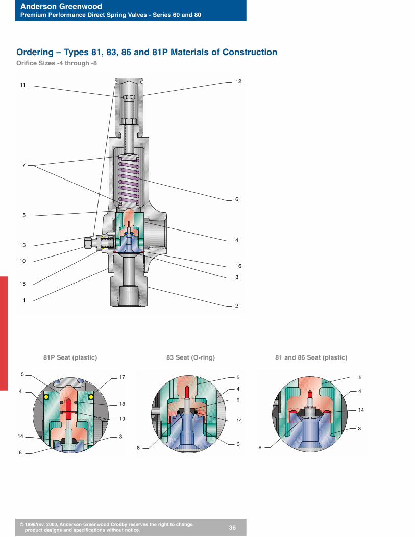
81P Seat (plastic) 83 Seat (O-ring) 81 and 86 Seat (plastic)
Ordering – Types 81, 83, 86 and 81P Materials of Construction Orifice Sizes -4 through -8
11
7
5
13
12
6
16
21
3
4
10
15
17
18
19
3
8
14
4
55
4
14
38
9
5
4
14
3
8
Anderson GreenwoodPremium Performance Direct Spring Valves - Series 60 and 80
© 1996/rev. 2000, Anderson Greenwood Crosby reserves the right to change product designs and specifications without notice. 37
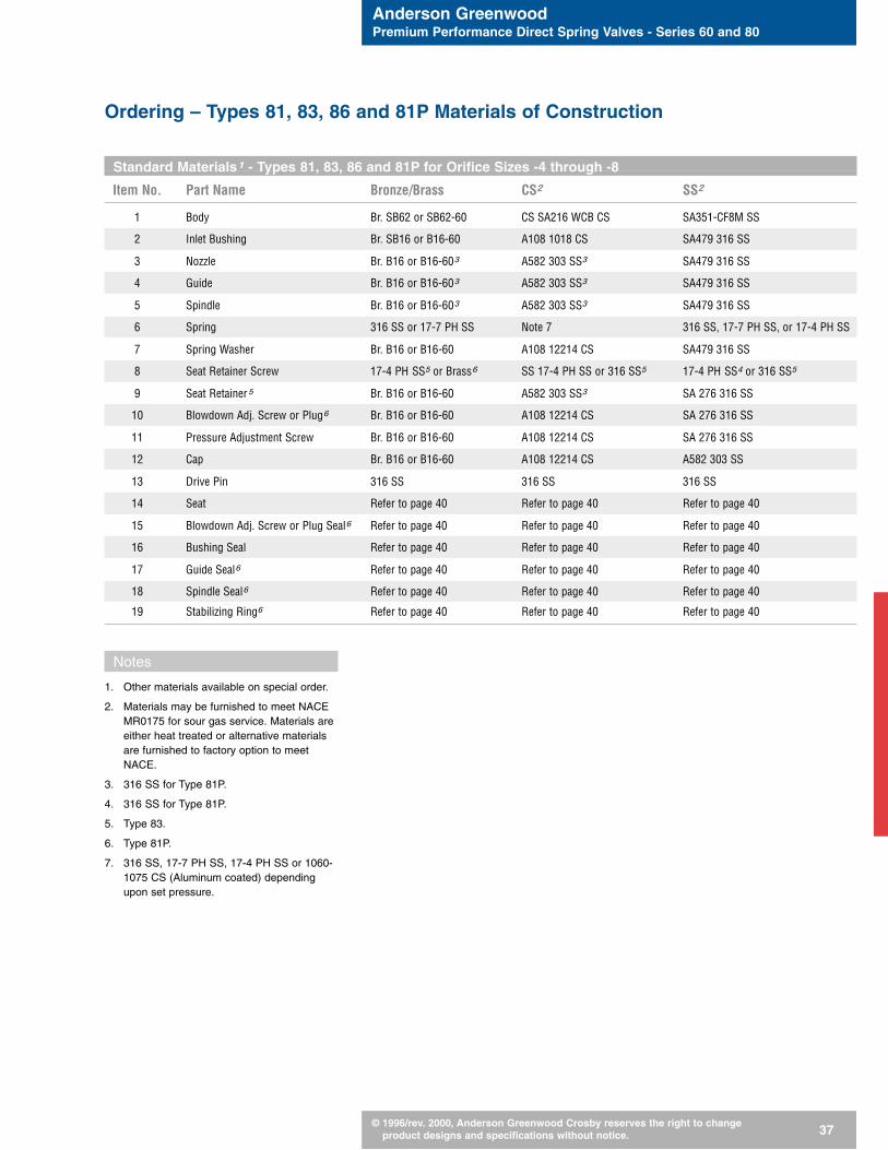
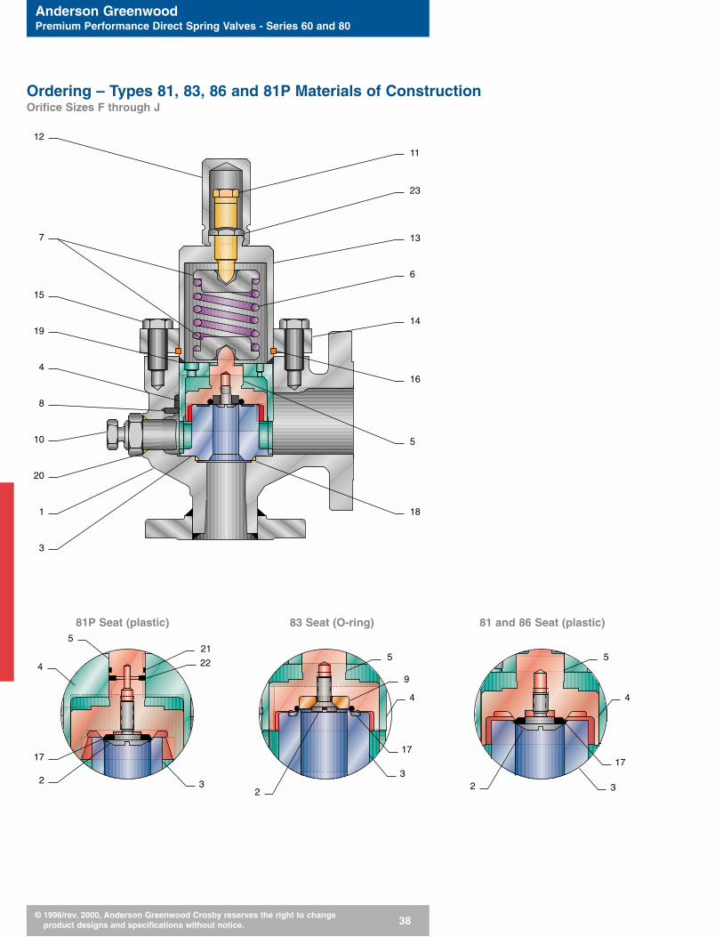
Standard Materials1 - Types 81, 83, 86 and 81P for Orifice Sizes -4 through -8
Item No. Part Name Bronze/Brass CS2 SS2
1 Body Br. SB62 or SB62-60 CS SA216 WCB CS SA351-CF8M SS
2 Inlet Bushing Br. SB16 or B16-60 A108 1018 CS SA479 316 SS
3 Nozzle Br. B16 or B16-603 A582 303 SS3 SA479 316 SS
4 Guide Br. B16 or B16-603 A582 303 SS3 SA479 316 SS
5 Spindle Br. B16 or B16-603 A582 303 SS3 SA479 316 SS
6 Spring 316 SS or 17-7 PH SS Note 7 316 SS, 17-7 PH SS, or 17-4 PH SS
7 Spring Washer Br. B16 or B16-60 A108 12214 CS SA479 316 SS
8 Seat Retainer Screw 17-4 PH SS5 or Brass6 SS 17-4 PH SS or 316 SS5 17-4 PH SS4 or 316 SS5
9 Seat Retainer5 Br. B16 or B16-60 A582 303 SS3 SA 276 316 SS
10 Blowdown Adj. Screw or Plug6 Br. B16 or B16-60 A108 12214 CS SA 276 316 SS
11 Pressure Adjustment Screw Br. B16 or B16-60 A108 12214 CS SA 276 316 SS
12 Cap Br. B16 or B16-60 A108 12214 CS A582 303 SS
13 Drive Pin 316 SS 316 SS 316 SS
14 Seat Refer to page 40 Refer to page 40 Refer to page 40
15 Blowdown Adj. Screw or Plug Seal6 Refer to page 40 Refer to page 40 Refer to page 40
16 Bushing Seal Refer to page 40 Refer to page 40 Refer to page 40
17 Guide Seal6 Refer to page 40 Refer to page 40 Refer to page 40
18 Spindle Seal6 Refer to page 40 Refer to page 40 Refer to page 40
19 Stabilizing Ring6 Refer to page 40 Refer to page 40 Refer to page 40
Notes
1. Other materials available on special order.
2. Materials may be furnished to meet NACEMR0175 for sour gas service. Materials areeither heat treated or alternative materialsare furnished to factory option to meetNACE.
3. 316 SS for Type 81P.
4. 316 SS for Type 81P.
5. Type 83.
6. Type 81P.
7. 316 SS, 17-7 PH SS, 17-4 PH SS or 1060-1075 CS (Aluminum coated) dependingupon set pressure.
Ordering – Types 81, 83, 86 and 81P Materials of Construction
Anderson GreenwoodPremium Performance Direct Spring Valves - Series 60 and 80
© 1996/rev. 2000, Anderson Greenwood Crosby reserves the right to change product designs and specifications without notice. 38
81P Seat (plastic) 83 Seat (O-ring) 81 and 86 Seat (plastic)
Ordering – Types 81, 83, 86 and 81P Materials of ConstructionOrifice Sizes F through J
5
4
17
2
21
22
32
5
4
3
17
9
2
5
4
3
17
12
7
15
19
4
8
10
20
1
3
11
23
13
6
14
16
5
18

Anderson GreenwoodPremium Performance Direct Spring Valves - Series 60 and 80
© 1996/rev. 2000, Anderson Greenwood Crosby reserves the right to change product designs and specifications without notice. 39
Standard Materials1 - Types 81, 83, 86 and 81P for Orifice Sizes F through J
Item No. Part Name Brass CS2 SS2
1 Body SB62 BRS SA216-WCB CS SA351-CF8M SS
2 Seat Retainer Screw 17-4 PH SS or 316 SS6 17-4 PH SS or 316 SS6 17-4 PH SS or 316 SS6
3 Nozzle SA479 316 SS3 A582 303 CS3, 4 SA479 316 SS3
4 Guide SA479 316 SS A582 303 CS4 SA479 316 SS
5 Spindle SA479 316 SS3 A582 303 CS3, 4 SA479 316 SS3
316 SS or 1060-1075 CS 316 SS or 1060-1075 CS 316 SS, 17-7 PH SS6 Spring
(Aluminum coated) (Aluminum coated) or 17-4 PH SS
7 Spring Washer SA479 316 SS A108 12214 CS SA479 316 SS
8 Drive Pin 316 SS 316 SS 316 SS
9 Seat Retainer6 SA479 316 SS SA582 303 SS SA479 316 SS
10 Blowdown Adj. Screw or Plug7 SA479 316 SS A108 12214 CS SA479 316 SS
11 Pressure Adjustment Screw SA479 316 SS A108 1213/1215 CS SA479 316 SS
12 Cap SA479 316 SS A108 12214 CS SA479 316 SS
13 Spring Bonnet SA479 316 SS SA105 CS5 SA479 316 SS
14 Bonnet Flange SA240 316 SS SA516 70 CS5 SA240 316 SS
15 Bonnet Bolting A193 B8M SS A449/A3255 A193 B8M SS
16 Split Ring A5H MT 304 SS A106 CS5 ASH MT 304 SS
17 Seat Refer to page 40 Refer to page 40 Refer to page 40
18 Nozzle Seal Refer to page 40 Refer to page 40 Refer to page 40
19 Bonnet Seal Refer to page 40 Refer to page 40 Refer to page 40
20 Blowdown Adj. Screw or Plug Seal7 Refer to page 40 Refer to page 40 Refer to page 40
21 Spindle Seal7 Refer to page 40 Refer to page 40 Refer to page 40
22 Stabilizing Ring7 Refer to page 40 Refer to page 40 Refer to page 40
23 Pressure Seal Refer to page 40 Refer to page 40 Refer to page 40
Notes
1. Other materials available on special order.
2. Materials may be furnished to meet NACEMR0175 for sour gas service. Materials areeither heat treated or alternative materialsare furnished to factory option to meetNACE.
3. 17-4 PH SS used for Type 81.
4. SA479 316 SS for Type 81P.
5. Zinc cobalt plated.
6. Type 83.
7. Type 81P.
Ordering – Types 81, 83, 86 and 81P Materials of Construction

Anderson GreenwoodPremium Performance Direct Spring Valves - Series 60 and 80
© 1996/rev. 2000, Anderson Greenwood Crosby reserves the right to change product designs and specifications without notice. 40
Standard Seat and Seal Options
Part Name Applicable Orifice Designation, Seat Option and Seal MaterialsOrifice Model 81 Model 86Sizes -4, -6, -8, F, G, H & J -4, -8, G & J
Seat All Teflon®1, 2 – PCTFE1, 2 – Vespel1, 2 Teflon®1, 2 – PEEK1, 2
Bushing Seal -4 thru -8 Glass Filled Teflon®1, 2 Glass Filled Teflon®1, 2
Nozzle Seal F thru J Teflon®1, 2 Teflon®1, 2
Bonnet Seal F thru J Glass Filled Teflon®1, 2 Glass Filled Teflon®1, 2
Blowdown Adj.All Teflon®1, 2 Teflon®1, 2
Screw Seal
Pressure Seal F thru J Teflon®1, 2 Teflon®1, 2
Standard Seat and Seal Options
Part Name Applicable Orifice Designation, Seat Option and Seal MaterialsOrifice Model 83 Model 81PSizes -4, -6, -8, F, G, H & J -4, -8, G & J
Seat All BUNA-N1 – EPR – Viton®2 Teflon®1, 2 – PCTFE1, 2
Bushing Seal -4 thru -8 BUNA-N1 – EPR – Viton®2 BUNA-N1 – EPR – Viton®2
Nozzle Seal F thru J BUNA-N1 – EPR – Viton®2 BUNA-N1 – EPR – Viton®2
Guide Seal -4 thru -8 — BUNA-N1 – EPR – Viton®2
Bonnet Seal F thru J BUNA-N1 – EPR – Viton®2 BUNA-N1 – EPR – Viton®2
Stabilizing Ring All — BUNA-N1 – EPR – Viton®2
Drag Ring G and J — Cast Monomer3
Spindle Seal All — BUNA-N1 – EPR – Viton®2
Blowdown AdjustmentAll Teflon®1, 2 Teflon®1, 2
Screw or Plug Seal
Pressure Seal F thru J Teflon®1, 2 —
Notes
1. Factory standard seat and seal materials.Other seat and seal materials available onspecial order.
2. Factory standard seat and seal material:NACE option.
3. G Orifice set pressure: 721 psig and above[49.7 barg and above].
J Orifice set pressure: 100 psig and above[6.9 barg and above].
Ordering – Materials of Construction

Anderson GreenwoodPremium Performance Direct Spring Valves - Series 60 and 80
© 1996/rev. 2000, Anderson Greenwood Crosby reserves the right to change product designs and specifications without notice. 41
After selecting valve type, orifice andmaterials of construction, the followinginformation might be required, depend-ing on the type of valve and otherrequirements:
Flanged ValvesIf ordering a flanged valve, separatelyspecify pressure class, facing, and finishfor both the inlet and outlet. To ensurebest delivery, please follow the specifiedflange practices as listed in the ANSIstandards. When the model number de-scribes flanged connections, the flangedimensions and finish will meet the ANSIstandards. Any deviation from the stan-dard must be clearly specified.
ServiceProvide the specific name of the fluid andstate to be relieved. When small amounts(including trace amounts) of other fluidsare present, indicate their name and con-centration. This is important for both theselection of metallic components as wellas the soft seats and seals. Note that cer-tain valve models are recommended forgas, liquid, or steam service.
TemperatureFurnish the normal operating temperatureand the relieving temperature. When theambient temperature varies significantlyfrom normal conditions, such as arctic en-vironments, furnish that temperature aswell. It is more important to select theseat and seal materials on the basis ofthe continuous service temperature. Thepressure containing parts of the pressurerelief valve should consider the three tem-perature conditions of continuous service,relieving, and ambient.
Set PressureSpecify set pressure in psig or in othercommonly accepted units. If set pressureis given in absolute terms, 14.7 psig [1.01barg] pressure will be deducted to estab-lish the factory setting. This gaugepressure value will be applied to the valvename plate.
Special RequirementsPlease specify the details of any specialprocedures you require during valve man-ufacturing. These might include unlistedaccessories, special quality assurance,material traceability, non-standard platingand surface finishes, non-destructive testrequirements, etc. Include required levelsof inspection and the parties or organiza-tions who will perform the inspections, ifany. Special requirements can impactprice and delivery.
Valve TaggingIf paper tags are requested at the time thevalve is ordered, they will be furnished atno additional cost. Other types of taggingare offered at additional cost. If you wouldlike metallic tags, please identify the spe-cific tag material, and tag numbers whenyou place your order.
DocumentationData submittals are not furnished for or-dered products unless specified. Certainstandard drawings, test reports, and certi-fications are available upon request.
Packing for ShipmentAll products are packed for normal do-mestic shipment from point of assemblyor stocking. Special packaging require-ments, such as export boxing, areavailable.
Ordering – Additional Information
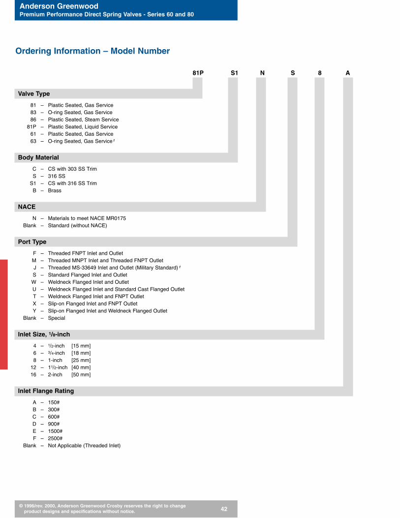
Anderson GreenwoodPremium Performance Direct Spring Valves - Series 60 and 80
© 1996/rev. 2000, Anderson Greenwood Crosby reserves the right to change product designs and specifications without notice. 42
Ordering Information – Model Number
81P S1 N S 8 A
Valve Type
81 – Plastic Seated, Gas Service83 – O-ring Seated, Gas Service86 – Plastic Seated, Steam Service
81P – Plastic Seated, Liquid Service61 – Plastic Seated, Gas Service63 – O-ring Seated, Gas Service1
Body Material
C – CS with 303 SS TrimS – 316 SS
S1 – CS with 316 SS TrimB – Brass
NACE
N – Materials to meet NACE MR0175Blank – Standard (without NACE)
Port Type
F – Threaded FNPT Inlet and OutletM – Threaded MNPT Inlet and Threaded FNPT OutletJ – Threaded MS-33649 Inlet and Outlet (Military Standard)1
S – Standard Flanged Inlet and OutletW – Weldneck Flanged Inlet and OutletU – Weldneck Flanged Inlet and Standard Cast Flanged OutletT – Weldneck Flanged Inlet and FNPT OutletX – Slip-on Flanged Inlet and FNPT OutletY – Slip-on Flanged Inlet and Weldneck Flanged Outlet
Blank – Special
Inlet Size, 1/8-inch
4 – 1/2-inch [15 mm]6 – 3/4-inch [18 mm]8 – 1-inch [25 mm]
12 – 11/2-inch [40 mm]16 – 2-inch [50 mm]
Inlet Flange Rating
A – 150#B – 300#C – 600#D – 900#E – 1500#F – 2500#
Blank – Not Applicable (Threaded Inlet)

Anderson GreenwoodPremium Performance Direct Spring Valves - Series 60 and 80
© 1996/rev. 2000, Anderson Greenwood Crosby reserves the right to change product designs and specifications without notice. 43
Note
1. 3-inch [80 mm] connections MS-33656.
Ordering Information – Model Number
16 A -8 L
Lift Lever
L – Packed Lift LeverBlank – Standard, without Lift Lever
Orifice
-4 – 0.049 in2 [0.32 cm2]-5 – 0.077 in2 [0.50 cm2] (Type 63B Only)-6 – 0.110 in2 [0.71 cm2] (D)-7 – 0.150 in2 [0.968 cm2] (Type 63B Only)-8 – 0.196 in2 [1.27 cm2] (Types 81, 83, 81P to 4000 psig [276 barg]) (E)-E – 0.196 in2 [1.27 cm2] (Types 83F, 81, 81P set over 4000 psig [276 barg])-F – 0.307 in2 [1.98 cm2]-G – 0.503 in2 [3.25 cm2]-H – 0.785 in2 [5.07 cm2]-J – 1.287 in2 [8.30 cm2]
Outlet Flange Rating
A – 150#B – 300#C – 600#D – 900#E – 1500#F – 2500#
Blank – Not Applicable (Threaded Outlet)
Outlet Size, 1/8-inch
6 – 3/4-inch [18 mm]8 – 1-inch [25 mm]
12 – 11/2-inch [40 mm]16 – 2-inch [50 mm]24 – 3-inch [80 mm]
Example:
81PS1NS8A16A – 8L81P liquid relief valve, A216 WCB CSbody, 316 SS trim, valve built to NACEMR0175, 1-inch [25 mm] - 150# RF x2-inch [50 mm] - 150# RF connections,0.196 in2 [1.27 cm2] orifice, packed liftlever.

Anderson GreenwoodPremium Performance Direct Spring Valves - Series 60 and 80
© 1996/rev. 2000, Anderson Greenwood Crosby reserves the right to change product designs and specifications without notice. 44
The code show below is stamped on the nameplate of the valve for easy identification inthe field.
Seat Material
B – BUNA-NV – Viton®
E – Ethylene PropyleneR – BUNA-N, CO2 Service (Seat Material Only) Type 83: -4, -6, -8
Orifice set pressures 720 psig [49.6 barg] and upA – AflasZ – Kalrez®
T – Teflon®
K – PCTFEW – VespelP – PEEK
Seal Material
B – BUNA-NV – Viton®
E – Ethylene PropyleneA – AflasZ – Kalrez®
T – Teflon®
Soft Goods Code

Anderson GreenwoodPremium Performance Direct Spring Valves - Series 60 and 80
© 1996/rev. 2000, Anderson Greenwood Crosby reserves the right to change product designs and specifications without notice. 45
Packed Lift LeverThe packed lift lever for all Series 80valves allows the valve to be manually ac-tuated at system operating pressures atleast 75 percent of set pressure, with noprocess venting through the lever mecha-nism.
Paragraph UG. 136(a) of the ASME Boilerand Pressure Vessel Code Section VIII,Division 1, requires a lifting device forpressure relief valves on air, steam, andhot water above 140°F [60°C].
Test GagsThe test gag can be provided to preventvalve opening during system hydrotests.
NACE Option
Essential option for sour gas service
This is a material option to meet thestress corrosion problems associated withsour gas service (hydrogen sulfide). Thewetted parts of the valve will meet the re-quirements of NACE MR0175. Althoughthe materials will vary from valve to valve,due to size and pressure rating, theymeet NACE requirements in all instances.
Availability of Accessories and Options
Accessory/Option Valve Type81 83 86 81P 61 63B
Packed Lift Lever Optional Optional Standard Optional Not Available Not Available
NACE Trim Optional Optional Optional Optional Not Available Not Available
Test Gag Optional Optional Optional Optional Not Available Not Available
Accessories and Options
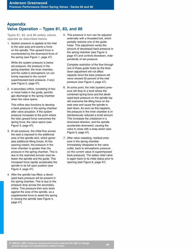
Anderson GreenwoodPremium Performance Direct Spring Valves - Series 60 and 80
© 1996/rev. 2000, Anderson Greenwood Crosby reserves the right to change product designs and specifications without notice. 46
AppendixValve Operation – Types 81, 83, and 86Types 81, 83, and 86 safety valvesoperate as described below.1. System pressure is applied at the inlet
to the seat area and exerts a force on the spindle. This upward force iscounteracted by the downward force ofthe spring (see Figure 1, page 47).
While the system pressure is belowset pressure, the pressure in thespring chamber, the inner chamber,and the outlet is atmospheric (or uni-formly exposed to the currentsuperimposed back pressure, if any)(see Figure 2, page 47).
2. A secondary orifice, consisting of twoor more holes in the guide, permitsgas discharge to the spring chamberwhen the valve opens.
This orifice also functions to develop a back pressure in the spring chamberafter valve actuation. If the systempressure increases to the point wherethe total upward force overcomes thespring force, the valve opens (seeFigure 3, page 47).
3. At set pressure, the initial flow acrossthe seat is exposed to the additionalarea of the spindle skirt, which gener-ates additional lifting forces. At thisopening instant, the pressure in theinner chamber is greater than thepressure in the spring chamber. This isdue to the restricted annular area be-tween the spindle and the guide. Thisincreased force rapidly accelerates thespindle to its full open position (seeFigure 4, page 47).
4. After the spindle has lifted, a devel-oped back pressure will be present inthe spring chamber. This is due to thepressure drop across the secondaryorifice. This pressure then acts downagainst the area of the spindle, as asupplemental force to assist the springin closing the spindle (see Figure 4,page 47).
5. This pressure in turn can be adjustedexternally with a threaded bolt, whichpartially restricts one of the guideholes. This adjustment varies theamount of developed back pressure inthe spring chamber (see Figure 4,page 47) and controls blowdown, inde-pendently of set pressure.
Complete restriction of the flow throughone of these guide holes by the blow-down adjustment will not affectcapacity since the back pressure willnever exceed 50 percent of the inletpressure (see Figure 4, page 47).
6. At some point, the inlet (system) pres-sure will drop to a level where thecombined spring force and the devel-oped back pressure on the spindle topwill overcome the lifting force on theseat area and cause the spindle tostart down. As soon as this happens,the pressure in the inner chamber is in-stantaneously reduced a small amount.This increases the unbalance in adownward direction, and the spindleaccelerates downward, causing thevalve to close with a snap action (seeFigure 5, page 47).
7. After valve reseating, residual pres-sure in the spring chamberimmediately dissipates to the valveoutlet, back to atmospheric pressure(or the current value of superimposedback pressure). The safety relief valveis again back to its initial status prior toopening (see Figure 6, page 47).

Anderson GreenwoodPremium Performance Direct Spring Valves - Series 60 and 80
© 1996/rev. 2000, Anderson Greenwood Crosby reserves the right to change product designs and specifications without notice. 47
AppendixValve Operation – Types 81, 83, and 86
Figure 4 Figure 5 Figure 6
Innerchamber
Guide
Springchamber
Spindle
Outlet
Inlet
Seat
100%
0%
100%
0%
SecondaryOrifice
100%
0%
100%
0%
SpindleSkirt
100%
0%
100%
0%
GuideHole
Blowdownadjustment
bolt
100%
0%
100%
0%
Blowdown
100%
0%
100%
0%
Figure 1 Figure 2 Figure 3

Anderson GreenwoodPremium Performance Direct Spring Valves - Series 60 and 80
© 1996/rev. 2000, Anderson Greenwood Crosby reserves the right to change product designs and specifications without notice. 48
Type 81P relief valves operate asdescribed below.1. With system pressure below set pres-
sure, the valve will be completelyleak-free, through the use of a replace-able soft seat (see Figure 7, page 49).
2. When the system pressure reachesset pressure, the valve will begin toopen with a small steady flow of liquid(see Figure 8, page 49).
The huddling chamber of the Type 81Pis similar to that of the Types 81, 83and 86, and functions to develop fulllift by 10 percent overpressure. Someconventional liquid safety relief valvesstill require 25 percent overpressure toachieve full opening and to reach theirrated capacity.
3. After initial flow at set pressure, the Type 81P valve will smoothly and progressively open with systempressure increase. The valve will reachfull lift and rated capacity by 10 per-cent overpressure (see Figure 9, page49).
4. When the full rated capacity is re-quired, the Type 81P will exhibit a blowdown of approximately 20 per-cent (see Figure 10, page 49). Whenfull relieving capacity is not required,the magnitude of blowdown will be-come progressively smaller. If thesystem pressure does not significantlyrise after reaching set pressure, thevalve will reclose at or near the setpressure, similar to the operation of amodulating pilot operated safety reliefvalve.
Specifically, the Type 61 and 63Bsafety valves operate identicallyand as described below.1. System pressure is applied at the inlet
to the seat area and exerts a force onthe spindle.
2. This upward force is counteracted by the larger, downward force of thespring, which, along with the soft seat,ensures that the valve is bubble-tight.
3. When system pressure increases to the point where the total upwardforce overcomes the spring force, the valve opens.
4. When the valve set pressure has beenreached, the spindle lifts slightly, andthe system pressure transfers its effectfrom the seat area to the larger spindleskirt area.
5. This area change, along with the spin-dle skirt redirecting the flow downward,generates additional lifting forces andsnaps the spindle into full lift by 10percent overpressure.
6. At some point, the system pressurewill drop to a level where the down-ward spring force can overcome thereduced spindle lifting force, and thevalve will reseat bubble-tight.
AppendixValve Operation – Types 81P, 61 and 63B

Anderson GreenwoodPremium Performance Direct Spring Valves - Series 60 and 80
© 1996/rev. 2000, Anderson Greenwood Crosby reserves the right to change product designs and specifications without notice. 49
Figure 8Figure 7
AppendixValve Operation – Types 81P
100%
Balancingseal
Stabilizingring
Seat
Huddlingchamber
100%
100%
110%
100%
Figure 9 Figure 10

Anderson GreenwoodPremium Performance Direct Spring Valves - Series 60 and 80
© 1996/rev. 2000, Anderson Greenwood Crosby reserves the right to change product designs and specifications without notice. 50
Types 81 and 83 Capacities1 - SCFM [Nm3/hr] Air - National Board Certified
Set Pressure -4 -6 -8 F G H Jpsig [barg] 0.049 in2 0.110 in2 0.196 in2 0.307 in2 0.503 in2 0.785 in2 1.287 in2
[0.32 cm2] [0.71 cm2] [1.26 cm2] [1.98 cm2] [3.25 cm2] [5.07 cm2] [8.30 cm2]
20 [1.38] 28 [45.0] 62 [99.7] 111 [178.5] 173 [278.2] 284 [456.7] 443 [712.3] 726 [1167.4]
40 [2.76] 43 [69.1] 97 [156.0] 172 [276.6] 270 [434.2] 442 [710.7] 689 [1107.9] 1130 [1817.0]
60 [4.14] 59 [94.9] 133 [213.9] 237 [381.1] 371 [596.6] 607 [976.1] 948 [1524.4] 1554 [2492.6]
80 [5.52] 75 [120.6] 169 [271.8] 301 [484.0] 472 [759.0] 773 [1243.0] 206 [1939.2] 1997 [3211.2]
100 [6.9] 91 [146.3] 205 [329.6] 366 [588.5] 573 [921.4] 938 [1508.3] 1464 [2354.1] 2401 [3860.8]
120 [8.3] 108 [173.7] 241 [387.5] 430 [691.4] 674 [1083.8] 1104 [1775.2] 1723 [2770.6] 2824 [4541.0]
140 [9.7] 124 [199.4] 278 [447.0] 495 [796.0] 775 [1246.2] 1269 [2040.6] 1981 [3185.5] 3248 [5222.8]
160 [11.0] 140 [225.1] 314 [504.9] 559 [898.9] 876 [1408.6] 1435 [2307.5] 2239 [3600.3] 3671 [5903.0]
180 [12.4] 156 [250.9] 350 [562.8] 624 [1003.4] 977 [1571.0] 1600 [2572.8] 2498 [4016.8] 4095 [6584.8]
200 [13.8] 172 [276.6] 386 [620.7] 688 [1106.3] 1078 [1733.4] 1766 [2839.7] 2756 [4431.7] 4518 [7264.9]
240 [16.6] 204 [328.0] 459 [738.1] 817 [1313.7] 1280 [2058.2] 2097 [3372.0] 3273 [5263.0] 5365 [8626.9]
280 [19.3] 237 [381.1] 531 [853.9] 946 [1521.2] 1482 [2383.1] 2428 [3904.2] 3789 [6092.7] 6212 [9988.9]
300 [20.7] 253 [406.8] 567 [911.7] 1011 [1625.7] 1583 [2545.5] 2594 [4171.2] 4048 [6509.2] 6636 [10,670.7]
340 [23.4] 285 [458.3] 640 [1029.1] 1140 [1833.1] 1785 [2870.3] 2925 [4703.4] 4564 [7338.9] 7483 [12,032.7]
380 [26.2] 317 [509.7] 712 [1144.9] 1269 [2040.6] 1987 [3195.1] 3256 [5235.7] 5081 [8170.2] 8330 [13,394.6]
400 [27.6] 333 [535.5] 748 [1202.8] 1333 [2143.5] 2088 [3357.5] 3421 [5501.0] 5339 [8585.1] 8754 [14,076.4]
440 [30.3] 366 [588.5] 821 [1320.2] 1462 [2350.9] 2290 [3682.3] 3752 [6033.2] 5856 [9416.5] 9601 [15,438.4]
480 [33.1] 398 [640.0] 893 [1435.9] 1591 [2558.3] 2492 [4007.1] 4083 [6565.5] 6373 [10,247.8] 10,448 [16,800.4]
500 [34.5] 414 [665.7] 929 [1493.8] 1656 [2662.9] 2593 [4169.5] 4249 [6832.4] 6631 [10,662.6] 10,871 [17,480.6]
600 [41.4] 495 [796.0] 1110 [1784.9] 1978 [3180.6] 3098 [4981.6] 5076 [8162.2] 7922 [12,738.6] 12,989 [20,886.3]
700 [48.3] 575 [924.6] 1291 [2075.9] 2301 [3700.0] 3603 [5793.6] 5904 [9493.6] 9214 [14,816.1] 15,106 [24,290.5]
800 [55.2] 656 [1054.9] 1472 [2367.0] 2623 [4217.8] 4109 [6607.3] 6732 [10,825.1] 10,506 [16,893.7] 17,224 [27,696.2]
900 [62.1] 736 [1183.5] 1653 [2658.0] 2946 [4737.2] 4614 [7419.3] 7559 [12,154.9] 11,797 [18,969.6] 19,342 [31,101.9]
1000 [69.0] 817 [1313.7] 1834 [2949.0] 3268 [5254.9] 5119 [8231.4] 8387 [13,486.3] 13,089 [21,047.1] 21,459 [34,506.0]
1500 [103.4] 1220 [1961.8] 2739 [4404.3] 4881 [7848.7] 7645 [12,293.16] 12,525 [20,140.2] 19,547 [31,431.6] 32,048 [51,533.2]
2000 [137.9] 1623 [2609.8] 3644 [5859.6] 6493 [10,440.7] 10,170 [16,353.4] 16,663 [26,774.1] 26,006 [41,817.7] — —
2500 [172.4] 2026 [3257.8] 4549 [7314.8] 8106 [13,034.5] 12,696 [20,415.2] 20,802 [33,449.6] 32,464 [52,202.1] — —
3000 [206.9] 2430 [3907.4] 5454 [8770.0] 9718 [15,626.5] 15,222 [24,476.98] — — — — — —
4000 [275.8] 3236 [5203.5] 7264 [11,680.5] 12,943 [20,812.3] 20,273 [32,599.0] — — — — — —
5000 [344.8] 4042 [6499.5] 9074 [14,591.0] 16,168 [25,998.1] — — — — — — — —
6000 [413.7] 4848 [7795.6] 10,884 [17,501.5] 19,393 [31,183.9] — — — — — — — —
7000 [482.7] 5655 [9093.2] 12,694 [20,412.0] — — — — — — — — — —
8000 [551.6] 6461 [10,389.3] 14,504 [23,322.4] — — — — — — — — — —
9000 [620.6] 7267 [11,685.3] 16,314 [26,232.9] — — — — — — — — — —
10,000 [689.5] 8073 [12,981.4] — — — — — — — — — — — —
1. 60°F [16°C], Z = 1.00; 10% overpressure or3 psig [0.21 barg] (whichever is greater).
2. Metric conversions:barg = psig x 0.06895cm2 = in2 x 6.4516
Nm3/hr = SCFM x 1.608°C = [°F - 32] x 0.5556
Notes
AppendixTypes 81 and 83 Capacities
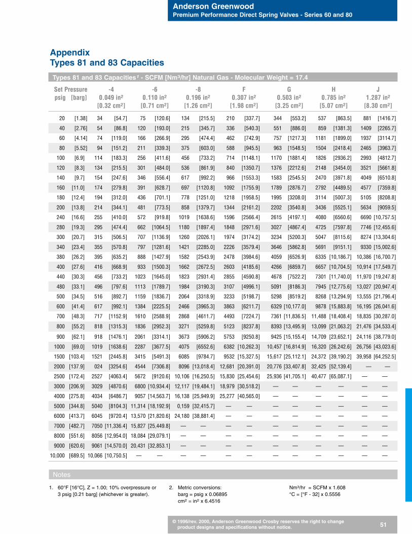
Anderson GreenwoodPremium Performance Direct Spring Valves - Series 60 and 80
© 1996/rev. 2000, Anderson Greenwood Crosby reserves the right to change product designs and specifications without notice. 51
1. 60°F [16°C], Z = 1.00; 10% overpressure or3 psig [0.21 barg] (whichever is greater).
2. Metric conversions:barg = psig x 0.06895cm2 = in2 x 6.4516
Nm3/hr = SCFM x 1.608°C = [°F - 32] x 0.5556
Types 81 and 83 Capacities1 - SCFM [Nm3/hr] Natural Gas - Molecular Weight = 17.4
Set Pressure -4 -6 -8 F G H Jpsig [barg] 0.049 in2 0.110 in2 0.196 in2 0.307 in2 0.503 in2 0.785 in2 1.287 in2
[0.32 cm2] [0.71 cm2] [1.26 cm2] [1.98 cm2] [3.25 cm2] [5.07 cm2] [8.30 cm2]
20 [1.38] 34 [54.7] 75 [120.6] 134 [215.5] 210 [337.7] 344 [553.2] 537 [863.5] 881 [1416.7]
40 [2.76] 54 [86.8] 120 [193.0] 215 [345.7] 336 [540.3] 551 [886.0] 859 [1381.3] 1409 [2265.7]
60 [4.14] 74 [119.0] 166 [266.9] 295 [474.4] 462 [742.9] 757 [1217.3] 1181 [1899.0] 1937 [3114.7]
80 [5.52] 94 [151.2] 211 [339.3] 375 [603.0] 588 [945.5] 963 [1548.5] 1504 [2418.4] 2465 [3963.7]
100 [6.9] 114 [183.3] 256 [411.6] 456 [733.2] 714 [1148.1] 1170 [1881.4] 1826 [2936.2] 2993 [4812.7]
120 [8.3] 134 [215.5] 301 [484.0] 536 [861.9] 840 [1350.7] 1376 [2212.6] 2148 [3454.0] 3521 [5661.8]
140 [9.7] 154 [247.6] 346 [556.4] 617 [992.2] 966 [1553.3] 1583 [2545.5] 2470 [3971.8] 4049 [6510.8]
160 [11.0] 174 [279.8] 391 [628.7] 697 [1120.8] 1092 [1755.9] 1789 [2876.7] 2792 [4489.5] 4577 [7359.8]
180 [12.4] 194 [312.0] 436 [701.1] 778 [1251.0] 1218 [1958.5] 1995 [3208.0] 3114 [5007.3] 5105 [8208.8]
200 [13.8] 214 [344.1] 481 [773.5] 858 [1379.7] 1344 [2161.2] 2202 [3540.8] 3436 [5525.1] 5634 [9059.5]
240 [16.6] 255 [410.0] 572 [919.8] 1019 [1638.6] 1596 [2566.4] 2615 [4197.1] 4080 [6560.6] 6690 [10,757.5]
280 [19.3] 295 [474.4] 662 [1064.5] 1180 [1897.4] 1848 [2971.6] 3027 [4867.4] 4725 [7597.8] 7746 [12,455.6]
300 [20.7] 315 [506.5] 707 [1136.9] 1260 [2026.1] 1974 [3174.2] 3234 [5200.3] 5047 [8115.6] 8274 [13,304.6]
340 [23.4] 355 [570.8] 797 [1281.6] 1421 [2285.0] 2226 [3579.4] 3646 [5862.8] 5691 [9151.1] 9330 [15,002.6]
380 [26.2] 395 [635.2] 888 [1427.9] 1582 [2543.9] 2478 [3984.6] 4059 [6526.9] 6335 [10,186.7] 10,386 [16,700.7]
400 [27.6] 416 [668.9] 933 [1500.3] 1662 [2672.5] 2603 [4185.6] 4266 [6859.7] 6657 [10,704.5] 10,914 [17,549.7]
440 [30.3] 456 [733.2] 1023 [1645.0] 1823 [2931.4] 2855 [4590.8] 4678 [7522.2] 7301 [11,740.0] 11,970 [19,247.8]
480 [33.1] 496 [797.6] 1113 [1789.7] 1984 [3190.3] 3107 [4996.1] 5091 [8186.3] 7945 [12,775.6] 13,027 [20,947.4]
500 [34.5] 516 [892.7] 1159 [1836.7] 2064 [3318.9] 3233 [5198.7] 5298 [8519.2] 8268 [13,294.9] 13,555 [21,796.4]
600 [41.4] 617 [992.1] 1384 [2225.5] 2466 [3965.3] 3863 [6211.7] 6329 [10,177.0] 9878 [15,883.8] 16,195 [26,041.6]
700 [48.3] 717 [1152.9] 1610 [2588.9] 2868 [4611.7] 4493 [7224.7] 7361 [11,836.5] 11,488 [18,408.4] 18,835 [30,287.0]
800 [55.2] 818 [1315.3] 1836 [2952.3] 3271 [5259.8] 5123 [8237.8] 8393 [13,495.9] 13,099 [21,063.2] 21,476 [34,533.4]
900 [62.1] 918 [1476.1] 2061 [3314.1] 3673 [5906.2] 5753 [9250.8] 9425 [15,155.4] 14,709 [23,652.1] 24,116 [38,779.0]
1000 [69.0] 1019 [1638.6] 2287 [3677.5] 4075 [6552.6] 6382 [10,262.3] 10,457 [16,814.9] 16,320 [26,242.6] 26,756 [43,023.6]
1500 [103.4] 1521 [2445.8] 3415 [5491.3] 6085 [9784.7] 9532 [15,327.5] 15,617 [25,112.1] 24,372 [39,190.2] 39,958 [64,252.5]
2000 [137.9] 024 [3254.6] 4544 [7306.8] 8096 [13,018.4] 12,681 [20,391.0] 20,776 [33,407.8] 32,425 [52,139.4] — —
2500 [172.4] 2527 [4063.4] 5672 [9120.6] 10,106 [16,250.5] 15,830 [25,454.6] 25,936 [41,705.1] 40,477 [65,087.1] — —
3000 [206.9] 3029 [4870.6] 6800 [10,934.4] 12,117 [19,484.1] 18,979 [30,518.2] — — — — — —
4000 [275.8] 4034 [6486.7] 9057 [14,563.7] 16,138 [25,949.9] 25,277 [40,565.0] — — — — — —
5000 [344.8] 5040 [8104.3] 11,314 [18,192.9] 0,159 [32,415.7] — — — — — — — —
6000 [413.7] 6045 [9720.4] 13,570 [21,820.6] 24,180 [38,881.4] — — — — — — — —
7000 [482.7] 7050 [11,336.4] 15,827 [25,449.8] — — — — — — — — — —
8000 [551.6] 8056 [12,954.0] 18,084 [29,079.1] — — — — — — — — — —
9000 [620.6] 9061 [14,570.0] 20,431 [32,853.1] — — — — — — — — — —
10,000 [689.5] 10,066 [10,750.5] — — — — — — — — — — — —
AppendixTypes 81 and 83 Capacities
Notes
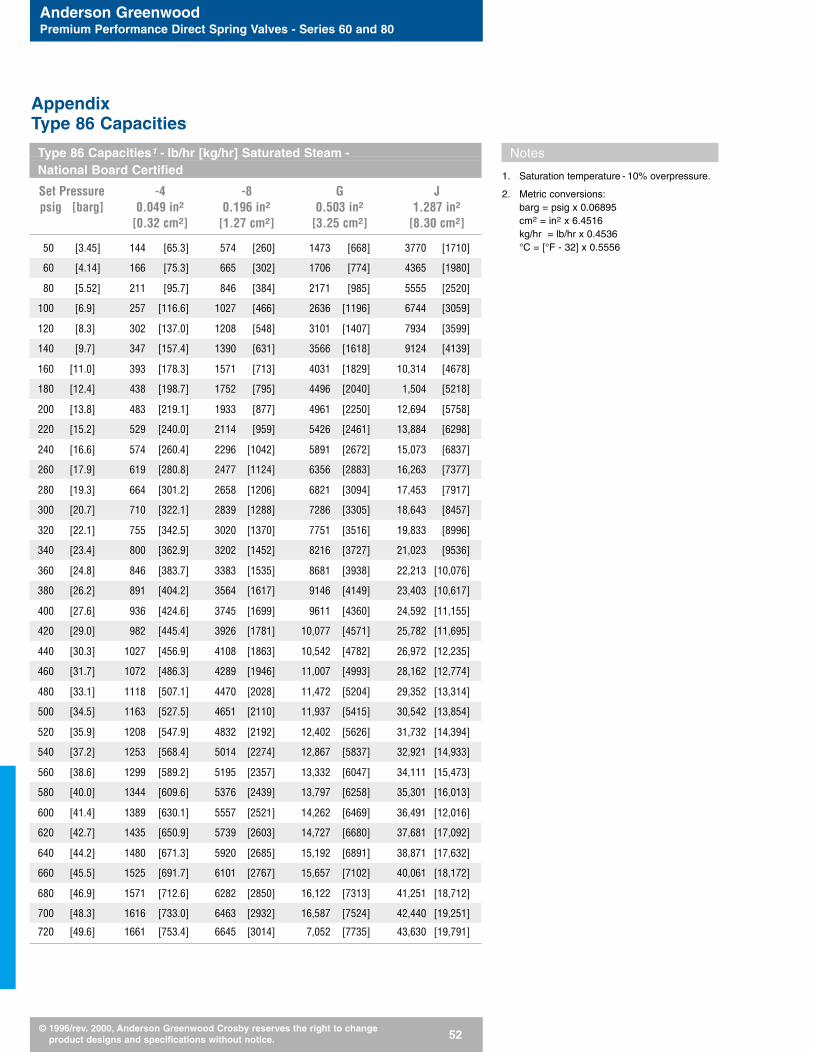
Anderson GreenwoodPremium Performance Direct Spring Valves - Series 60 and 80
© 1996/rev. 2000, Anderson Greenwood Crosby reserves the right to change product designs and specifications without notice. 52
Type 86 Capacities1 - lb/hr [kg/hr] Saturated Steam -National Board Certified
Set Pressure -4 -8 G Jpsig [barg] 0.049 in2 0.196 in2 0.503 in2 1.287 in2
[0.32 cm2] [1.27 cm2] [3.25 cm2] [8.30 cm2]
50 [3.45] 144 [65.3] 574 [260] 1473 [668] 3770 [1710]
60 [4.14] 166 [75.3] 665 [302] 1706 [774] 4365 [1980]
80 [5.52] 211 [95.7] 846 [384] 2171 [985] 5555 [2520]
100 [6.9] 257 [116.6] 1027 [466] 2636 [1196] 6744 [3059]
120 [8.3] 302 [137.0] 1208 [548] 3101 [1407] 7934 [3599]
140 [9.7] 347 [157.4] 1390 [631] 3566 [1618] 9124 [4139]
160 [11.0] 393 [178.3] 1571 [713] 4031 [1829] 10,314 [4678]
180 [12.4] 438 [198.7] 1752 [795] 4496 [2040] 1,504 [5218]
200 [13.8] 483 [219.1] 1933 [877] 4961 [2250] 12,694 [5758]
220 [15.2] 529 [240.0] 2114 [959] 5426 [2461] 13,884 [6298]
240 [16.6] 574 [260.4] 2296 [1042] 5891 [2672] 15,073 [6837]
260 [17.9] 619 [280.8] 2477 [1124] 6356 [2883] 16,263 [7377]
280 [19.3] 664 [301.2] 2658 [1206] 6821 [3094] 17,453 [7917]
300 [20.7] 710 [322.1] 2839 [1288] 7286 [3305] 18,643 [8457]
320 [22.1] 755 [342.5] 3020 [1370] 7751 [3516] 19,833 [8996]
340 [23.4] 800 [362.9] 3202 [1452] 8216 [3727] 21,023 [9536]
360 [24.8] 846 [383.7] 3383 [1535] 8681 [3938] 22,213 [10,076]
380 [26.2] 891 [404.2] 3564 [1617] 9146 [4149] 23,403 [10,617]
400 [27.6] 936 [424.6] 3745 [1699] 9611 [4360] 24,592 [11,155]
420 [29.0] 982 [445.4] 3926 [1781] 10,077 [4571] 25,782 [11,695]
440 [30.3] 1027 [456.9] 4108 [1863] 10,542 [4782] 26,972 [12,235]
460 [31.7] 1072 [486.3] 4289 [1946] 11,007 [4993] 28,162 [12,774]
480 [33.1] 1118 [507.1] 4470 [2028] 11,472 [5204] 29,352 [13,314]
500 [34.5] 1163 [527.5] 4651 [2110] 11,937 [5415] 30,542 [13,854]
520 [35.9] 1208 [547.9] 4832 [2192] 12,402 [5626] 31,732 [14,394]
540 [37.2] 1253 [568.4] 5014 [2274] 12,867 [5837] 32,921 [14,933]
560 [38.6] 1299 [589.2] 5195 [2357] 13,332 [6047] 34,111 [15,473]
580 [40.0] 1344 [609.6] 5376 [2439] 13,797 [6258] 35,301 [16,013]
600 [41.4] 1389 [630.1] 5557 [2521] 14,262 [6469] 36,491 [12,016]
620 [42.7] 1435 [650.9] 5739 [2603] 14,727 [6680] 37,681 [17,092]
640 [44.2] 1480 [671.3] 5920 [2685] 15,192 [6891] 38,871 [17,632]
660 [45.5] 1525 [691.7] 6101 [2767] 15,657 [7102] 40,061 [18,172]
680 [46.9] 1571 [712.6] 6282 [2850] 16,122 [7313] 41,251 [18,712]
700 [48.3] 1616 [733.0] 6463 [2932] 16,587 [7524] 42,440 [19,251]
720 [49.6] 1661 [753.4] 6645 [3014] 7,052 [7735] 43,630 [19,791]
Notes
1. Saturation temperature - 10% overpressure.
2. Metric conversions:barg = psig x 0.06895cm2 = in2 x 6.4516kg/hr = lb/hr x 0.4536°C = [°F - 32] x 0.5556
AppendixType 86 Capacities
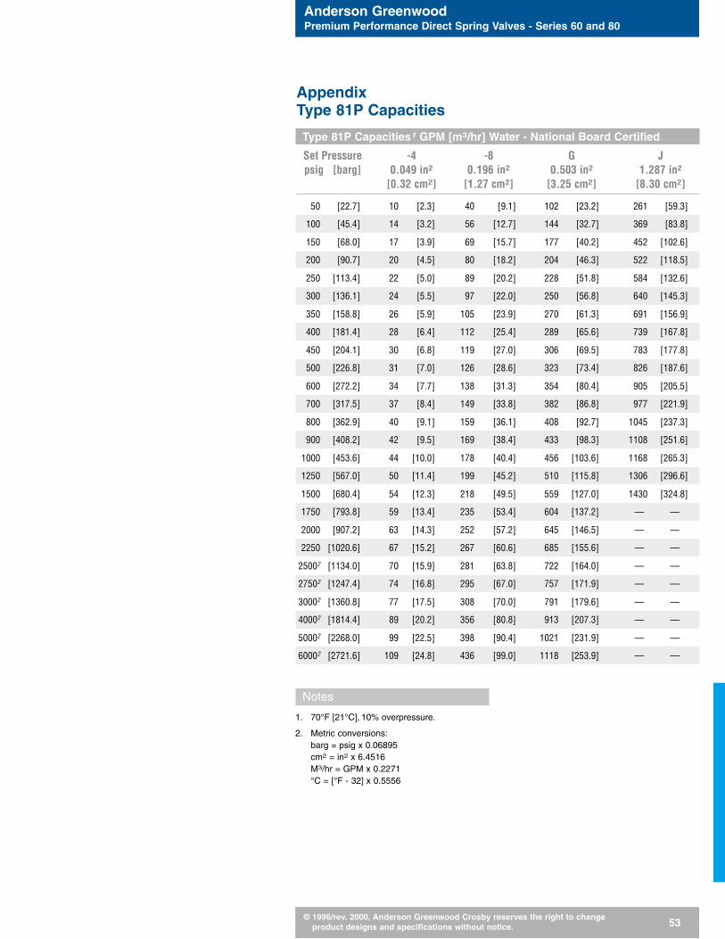
Anderson GreenwoodPremium Performance Direct Spring Valves - Series 60 and 80
© 1996/rev. 2000, Anderson Greenwood Crosby reserves the right to change product designs and specifications without notice. 53
Type 81P Capacities1 GPM [m3/hr] Water - National Board Certified
Set Pressure -4 -8 G Jpsig [barg] 0.049 in2 0.196 in2 0.503 in2 1.287 in2
[0.32 cm2] [1.27 cm2] [3.25 cm2] [8.30 cm2]
50 [22.7] 10 [2.3] 40 [9.1] 102 [23.2] 261 [59.3]
100 [45.4] 14 [3.2] 56 [12.7] 144 [32.7] 369 [83.8]
150 [68.0] 17 [3.9] 69 [15.7] 177 [40.2] 452 [102.6]
200 [90.7] 20 [4.5] 80 [18.2] 204 [46.3] 522 [118.5]
250 [113.4] 22 [5.0] 89 [20.2] 228 [51.8] 584 [132.6]
300 [136.1] 24 [5.5] 97 [22.0] 250 [56.8] 640 [145.3]
350 [158.8] 26 [5.9] 105 [23.9] 270 [61.3] 691 [156.9]
400 [181.4] 28 [6.4] 112 [25.4] 289 [65.6] 739 [167.8]
450 [204.1] 30 [6.8] 119 [27.0] 306 [69.5] 783 [177.8]
500 [226.8] 31 [7.0] 126 [28.6] 323 [73.4] 826 [187.6]
600 [272.2] 34 [7.7] 138 [31.3] 354 [80.4] 905 [205.5]
700 [317.5] 37 [8.4] 149 [33.8] 382 [86.8] 977 [221.9]
800 [362.9] 40 [9.1] 159 [36.1] 408 [92.7] 1045 [237.3]
900 [408.2] 42 [9.5] 169 [38.4] 433 [98.3] 1108 [251.6]
1000 [453.6] 44 [10.0] 178 [40.4] 456 [103.6] 1168 [265.3]
1250 [567.0] 50 [11.4] 199 [45.2] 510 [115.8] 1306 [296.6]
1500 [680.4] 54 [12.3] 218 [49.5] 559 [127.0] 1430 [324.8]
1750 [793.8] 59 [13.4] 235 [53.4] 604 [137.2] — —
2000 [907.2] 63 [14.3] 252 [57.2] 645 [146.5] — —
2250 [1020.6] 67 [15.2] 267 [60.6] 685 [155.6] — —
25002 [1134.0] 70 [15.9] 281 [63.8] 722 [164.0] — —
27502 [1247.4] 74 [16.8] 295 [67.0] 757 [171.9] — —
30002 [1360.8] 77 [17.5] 308 [70.0] 791 [179.6] — —
40002 [1814.4] 89 [20.2] 356 [80.8] 913 [207.3] — —
50002 [2268.0] 99 [22.5] 398 [90.4] 1021 [231.9] — —
60002 [2721.6] 109 [24.8] 436 [99.0] 1118 [253.9] — —
Notes
1. 70°F [21°C], 10% overpressure.
2. Metric conversions:barg = psig x 0.06895cm2 = in2 x 6.4516M3/hr = GPM x 0.2271°C = [°F - 32] x 0.5556
AppendixType 81P Capacities

Anderson GreenwoodPremium Performance Direct Spring Valves - Series 60 and 80
© 1996/rev. 2000, Anderson Greenwood Crosby reserves the right to change product designs and specifications without notice. 54
Type 61 Capacities1 - SCFM [Nm3/hr]
Set Pressure Air, National Board Certified Natural Gas2
psig [barg] -6 -60.110 in2 [0.71 cm2] 0.110 in2 [0.71 cm2]
30 [2.07] 84 [135.1] 105 [168.8]
40 [2.76] 104 [167.2] 130 [209.0]
60 [4.13] 143 [229.9] 178 [286.2]
80 [5.52] 182 [292.6] 227 [365.0]
100 [6.90] 221 [355.4] 275 [442.2]
120 [8.27] 260 [418.1] 324 [521.0]
140 [9.65] 299 [480.8] 372 [598.2]
160 [11.0] 338 [543.5] 421 [677.0]
180 [12.4] 376 [604.6] 470 [755.8]
200 [13.8] 415 [667.3] 518 [832.9]
220 [15.2] 454 [730.0] 567 [911.7]
240 [16.5] 493 [792.7] 615 [988.9]
260 [17.9] 532 [855.5] 664 [1067.7]
280 [19.3] 571 [918.2] 712 [1144.9]
300 [20.7] 610 [980.9] 761 [1223.7]
320 [22.1] 649 [1043.6] 809 [1300.9]
340 [23.4] 688 [1106.3] 858 [1379.7]
360 [24.8] 727 [1169.0] 907 [1458.5]
380 [26.2] 766 [1231.7] 955 [1535.6]
400 [27.6] 805 [1294.4] 1004 [1614.4]
420 [29.0] 844 [1357.2] 1052 [1691.6]
440 [30.3] 883 [1419.9] 1101 [1770.4]
460 [31.7] 922 [1482.6] 1149 [1847.6]
480 [33.1] 961 [1545.3] 1198 [1926.4]
500 [34.5] 1000 [1608.0] 1247 [2005.2]
Notes
1. 60°F [16°C], Z = 1.00; 10% overpressure.
2. Molecular weight = 17.4.
3. Metric conversions:barg = psig x 0.06895cm2 = in2 x 6.4516°C = [°F - 32] x 0.5556Nm3/hr = SCFM x 1.608
AppendixType 61 Capacities

Anderson GreenwoodPremium Performance Direct Spring Valves - Series 60 and 80
© 1996/rev. 2000, Anderson Greenwood Crosby reserves the right to change product designs and specifications without notice. 55
Type 63B Capacities1 - SCFM [Nm3/hr]
Set Air, National Board Certified Natural Gas2
Pressure -5 -7 -5 -7psig [barg] 0.077 in2 0.150 in2 0.077 in2 0.150 in2
[0.497 cm2] [0.968 cm2] [0.497 cm2] [0.968 cm2]
40 [2.76] 69 [111.0] — — 86 [138.3] — —
60 [4.14] 95 [152.8] 191 [307.1] 119 [191.4] 238 [382.7]
80 [5.52] 121 [194.6] 243 [390.7] 151 [242.8] 304 [488.8]
100 [6.90] 147 [236.4] 296 [476.0] 183 [294.3] 369 [593.4]
120 [8.27] 173 [278.2] 348 [559.6] 216 [347.3] 434 [697.9]
140 [9.65] 199 [320.0] 400 [643.2] 248 [398.8] 499 [802.4]
160 [11.03] 225 [361.8] 452 [726.8] 281 [451.8] 564 [906.9]
180 [12.41] 251 [403.6] 504 [810.4] 313 [503.3] 629 [1011.4]
200 [13.79] 277 [445.4] 556 [894.1] 345 [554.8] 694 [1116.0]
220 [15.17] 303 [487.2] 608 [977.7] 378 [607.8] 759 [1220.5]
240 [16.55] 329 [529.0] 661 [1062.9] 240 [385.9] 824 [1325.0]
260 [17.92] 355 [570.8] 713 [1146.5] 260 [418.1] 889 [1429.5]
280 [19.31] 381 [612.6] 765 [1230.1] 280 [450.2] 954 [1534.0]
300 [20.69] 407 [654.5] 817 [1313.7] 300 [482.4] 1019 [1638.6]
320 [22.06] 433 [696.3] 869 [1397.4] 320 [514.6] 1084 [1743.1]
340 [23.44] 459 [738.1] 921 [1481.0] 340 [546.7] 1149 [1847.6]
360 [24.82] 485 [779.9] 973 [1565.6] 360 [578.9] 1214 [1952.1]
380 [26.20] 511 [821.7] — — 380 [611.0] — —
400 [27.58] 537 [863.5] — — 400 [643.2] — —
420 [28.96] 563 [905.3] — — 420 [675.4] — —
440 [30.34] 588 [945.5] — — 440 [707.5] — —
460 [31.72] 614 [987.3] — — 460 [739.7] — —
480 [33.10] 640 [1029.1] — — 480 [771.8] — —
500 [34.48] 666 [1070.9] — — 500 [804.0] — —
520 [35.85] 692 [1112.7] — — 520 [836.2] — —
Notes
1. 60°F [16°C], Z = 1.00; 10% overpressure.
2. Molecular weight = 17.4.
3. Metric conversions:barg = psig x 0.06895cm2 = in2 x 6.4516°C = [°F - 32] x 0.5556Nm3/hr = SCFM x 1.608
AppendixType 63B Capacities

Anderson GreenwoodPremium Performance Direct Spring Valves - Series 60 and 80
© 1996/rev. 2000, Anderson Greenwood Crosby reserves the right to change product designs and specifications without notice. 56
Seat Tightness PerformanceSpecificationsAll pressure relief valves are checkedfor seat leakage per procedures out-lined in API 527.
The following operating pressures willallow for bubble-tight seat sealing per-formance.
Valve Type Set Pressure Range Operating Pressure Range
100 psig [6.9 barg] and above 0% to 95% of set81 and 83 50 to 99 psig [3.4 to 6.8 barg] 0% to 90% of set
Below 50 psig [3.4 barg] 0% to 85% of set
100 psig [6.9 barg] and above 0% to 92.5% of set81P
Below 100 psig [6.9 barg] 0% to 80% of set
86100 psig [6.9 barg] and above 0% to 95% of set
50 to 99 psig [3.4 to 6.8 barg] 0% to 90% of set
100 psig [6.9 barg] and above 0% to 95% of set61 and 63
Below 100 psig [6.9 barg] 0% to 90% of set
Appendix

© 1996/rev. 2000 Anderson Greenwood Crosby Printed in USA
Premium Performance Direct SpringOperated Pressure Relief ValveSeries 60 and 80 CatalogRevised September 2000Catalog: 60/80 DS-US.96
Corporate Headquarters and Operations CenterP.O. Box 944Stafford, Texas 77497, USATelephone: (281) 274-4400, Fax: (281) 240-1800
Operations CentersCrosby Road, Market Harborough, Leics LE16 9EE, UKTelephone: 44-1858-467281, Fax: 44-1858-434728
No. 45, Tuas Avenue 9Jurong, SingaporeTelephone: 65-861-1655, Fax: 65-861-8310
Flow Control
ANDERSONGREENWOODCROSBY