Embed Size (px)
Citation preview

This is a repository copy of Anatomy and facies distribution of terminal lobes in ephemeral fluvial successions: Jurassic Tordillo Formation, Neuquén Basin, Argentina.
White Rose Research Online URL for this paper:http://eprints.whiterose.ac.uk/156387/
Version: Accepted Version
Article:
Coronel, MD, Isla, MF, Veiga, GD et al. (2 more authors) (2020) Anatomy and facies distribution of terminal lobes in ephemeral fluvial successions: Jurassic Tordillo Formation, Neuquén Basin, Argentina. Sedimentology, 67 (5). sed.12712. pp. 2596-2624. ISSN 0037-0746
https://doi.org/10.1111/sed.12712
© 2020 The Authors. Sedimentology © 2020 International Association of Sedimentologists.This is the peer reviewed version of the following article: Coronel, M.D., Isla, M.F., Veiga, G.D., Mountney, N.P. and Colombera, L. (2020), Anatomy and facies distribution of terminal lobes in ephemeral fluvial successions: Jurassic Tordillo Formation, Neuquén Basin, Argentina. Sedimentology, 67: 2596-2624. , which has been published in final form at https://doi.org/10.1111/sed.12712. This article may be used for non-commercial purposes in accordance with Wiley Terms and Conditions for Use of Self-Archived Versions.
[email protected]://eprints.whiterose.ac.uk/
Reuse
Items deposited in White Rose Research Online are protected by copyright, with all rights reserved unless indicated otherwise. They may be downloaded and/or printed for private study, or other acts as permitted by national copyright laws. The publisher or other rights holders may allow further reproduction and re-use of the full text version. This is indicated by the licence information on the White Rose Research Online record for the item.
Takedown
If you consider content in White Rose Research Online to be in breach of UK law, please notify us by emailing [email protected] including the URL of the record and the reason for the withdrawal request.

1
Anatomy and facies distribution of terminal lobes in ephemeral fluvial successions: Jurassic Tordillo Formation, Neuquén Basin, Argentina
MARINA D. CORONEL1*, MANUEL F. ISLA1, GONZALO D. VEIGA1, NIGEL P. MOUNTNEY2 and LUCA COLOMBERA2
1) Centro de Investigaciones Geológicas (CONICET-Universidad Nacional de La Plata), Diagonal 113
#275 (B1904DPK), La Plata, Argentina.
2) Fluvial & Eolian Research Group, School of Earth and Environment, University of Leeds, Leeds LS2
9JT, UK.
*E-mail: [email protected]
Abstract
In terminal fluvial-fan systems, characteristic proximal-to-distal variations in sedimentary architectures are recognized to arise from progressive downstream loss of water discharge related to both infiltration and evaporation. This work aims to elucidate downstream trends in facies and architecture across the medial and distal zones of terminal-fan systems, which record transitions from deposits of channel elements to lobe- and sheet-like elements. This is achieved via a detailed characterization of ancient ephemeral fluvial deposits of the well-exposed Kimmeridgian Tordillo Formation (Neuquén Basin, Argentina). The fine sand- and silt-prone succession associated with the medial-to-distal sectors of the system has been studied to understand relationships between depositional processes and resulting architectures. Facies and architectural-element analyses, and quantification of resulting sedimentological data at multiple scales, have been undertaken to characterize sedimentary facies, facies transitions, bed types, architectural elements and larger-scale architectural styles. Eight bed types with distinct internal facies transitions are defined and interpreted in terms of different types of flood events. Channelized and non-channelized architectural elements are defined based on their constituent bed types and their external geometry. The most common elements are terminal lobes, which are composite bodies within which largely unconfined sandy deposits are stacked in a compensational manner; a hierarchical arrangement of internal components is recognised. Proximal feeder-channel avulsion events likely controlled the evolution of terminal-lobe elements and their spatiotemporal shifts. Stratigraphic relations between architectural elements record system-wide trends, whereby a proximal sector dominated by channel elements passes downstream via a gradational transition to a medial sector dominated by sandy terminal-lobe elements, which in turn passes further downstream to a distal sector dominated by silty terminal lobe-margin and fringing deposits. This work enhances our understanding of the stratigraphic record of terminal fluvial systems at multiple scales, and provides insight that can be applied to predict the facies and architectural complexity of terminal fluvial successions.
Key words
Fluvial, ephemeral, dryland, terminal lobes, Tordillo Formation, Neuquén Basin
1. INTRODUCTION
A terminal fan is a type of fluvial system that has been classically associated with ephemeral stream-flow behaviour, in which the termination of channelized fluvial flow occurs before reaching a sea or a lake. Friend (1978) first introduced the name terminal fan, and this term was later adopted by other authors (Parkash et al., 1983; Tunbridge, 1984; Kelly & Olsen, 1993), who collectively presented examples which culminated in the development of a terminal fan facies

2
model. This model has been widely applied and subsequently refined (e.g., Nichols & Hirst 1998; Tooth, 2000; Sáez et al., 2007; Fisher et al., 2007). However, detailed aspects of the model have been questioned by workers who have argued that in apparently distributary channel networks, multiple channels are not necessarily coevally active across broad areas of the system during flood events (Bridge, 2006; North & Warwick, 2007; Nichols & Fisher, 2007; North & Davidson, 2012). Instead, these authors have proposed facies models in which the apparent distributive networks of channels are actually constructed over longer periods as a result of repeated nodal avulsions and the subsequent superimposition of active channels over older abandoned ones. Implicit in this refinement is the appreciation that only a modest part of a terminal fan system is typically active during any given flood event (North & Warwick, 2007; Nichols & Fisher, 2007; North & Davidson, 2012).
More recent studies have adopted the concept of the ‘distributive fluvial system’ (DFS) to refer to the deposit of a fluvial system for which the planform develops a radial, distributive channel pattern (Hartley et al., 2010; Weissmann et al., 2010). DFS facies models do not imply that all channel belts are simultaneously active across a fan surface, though it is common for several channel belts to be active at one particular time (Weissman et al., 2010; Hartley et al., 2010; Weissman et al., 2013).
Regardless of differences in terminology inherent to each of the different facies models proposed for terminal fluvial-fan systems (e.g. Hampton & Horton, 2007; Fisher et al., 2008; Cain & Mountney, 2009), each has commonalities, notably the general division of the fluvial system into three main zones: a proximal feeder zone, a medial fluvial zone, and a distal basinal zone, each of which can be differentiated on the basis of their facies types and proportions, and their architectural elements (Fig. 1).
Figure 1: Classic model for ephemeral river systems. A) General model in which there is a three-fold sub-division of the system based on downstream variations and fluvial architecture. B) Detail of the medial to distal zone.
Criteria for the recognition of the preserved deposits of ephemeral fluvial systems in the ancient sedimentary record is primarily based on the identification of sedimentological characteristics indicative of progressive downstream loss of fluvial discharge due to a combination of infiltration, evaporation and a down-system decrease in the gradient of the depositional surface (Friend, 1978; Parkash et al. 1983; Tunbridge, 1984; Olsen, 1987; Kelly & Olsen, 1993). A notable implication

3
of these downstream trends is the sedimentological complexity of the medial and distal zones of the system, especially in the region of termination of channelized fluvial flow. In these parts of terminal fans, the generally poor lateral confinement of flows within shallow channels tends to give rise to deposits of varied nature and characteristics, notably where channel elements pass downstream into lobe- and sheet-like elements. In the distal parts of a fan, the proportion of fine-grained sediments (clay and silt) typically increases markedly (Sadler & Kelly, 1993; Hampton & Horton, 2007; Cain & Mountney, 2009).
Recently, authors have described deposits of modern terminal splays, characterizing their morphology, their stages of development, their constituent sedimentary facies and the styles of fluvial termination (Lang et al., 2004; Tooth, 2005; Billi, 2007; Fisher et al., 2008; Donselaar et al., 2013, Van Toorenenburg et al., 2018). However, relatively little is known of the mechanisms by which these terminal deposits accumulate and become preserved in the sedimentary record, especially within terminal lobes.
The aim of this study is to undertake a detailed characterization of ancient distributive fluvial system deposits associated with the development of terminal fans in the well-exposed sedimentary succession of the Kimmeridgian Tordillo Formation, Neuquén Basin (Argentina). The fine sand- and silt-prone succession associated with the medial-to-distal sectors of the system has been studied to define in detail the relationship between channel elements and unconfined lobe elements, highlighting their constituent deposits and large-scale architectural relationships. Specific research objectives are: (i) to undertake a quantitative lithofacies analysis and demonstrate the most significant facies transitions in the medial to distal sectors of the system; (ii) to demonstrate that terminal deposits are composite bodies accumulated as a hierarchy of elements in a way that has not been previously recognized for other similar fluvial successions; (iii) to demonstrate how the different sub-environments that constitute the system are related; (iv) to analyse the long-term evolution of the system; (v) to critically evaluate existing facies models for ephemeral fluvial systems and to propose a new facies model for distal fluvial successions dominated by terminal-lobe elements.
2. GEOLOGICAL SETTING
The Neuquén Basin is located in west central Argentina and eastern Chile between 36° and 40°S. The basin has an areal extent of approximately 160,000 km2 (Vergani et al., 1995). The Neuquén Basin has a complex history, but mostly evolved as an ensialic back-arc basin associated with the easterly oriented subduction along the proto-Pacific margin of Gondwana, between a volcanic arc to the west and two major uplifted cratonic areas to the northeast and southwest. (Digregorio et al., 1984; Legarreta & Uliana, 1991). The basin fill is more than 4000 m thick and is composed of a near-continuous succession of Late Triassic to Early Cenozoic siliciclastic deposits of continental and marine origin, as well as carbonates and evaporites (Gulisano & Gutiérrez Pleiming, 1994; Vergani et al., 1995).
Given the long-lived occurrence and recurrence of semi-arid, arid and even hyper-arid climatic conditions during the evolution of the Neuquén Basin, the resultant preserved sedimentary record of ephemeral fluvial systems is of notable importance (Leanza, 2003; Spalletti & Colombo Piñol, 2005; Sánchez et al., 2006; Spalletti & Veiga, 2007; Sánchez & Asurmendi, 2015). Moreover, several units that constitute the fill of the Neuquén Basin act as economically valuable conventional hydrocarbon reservoirs, most notably in the northern sector of Neuquén and adjoining southern Mendoza (Maretto et al., 2002; Spalletti et al., 2011). Although several units have been interpreted as fluvial systems accumulated under the influence of arid-climate conditions (e.g. Leanza, 2003; Garrido, 2010) (Fig. 2), there have hitherto been no detailed studies of the distal parts of ephemeral fluvial successions that form part of the fill of the Neuquén Basin.
Both for its accessibility and for the quality of exposure, a sedimentary succession of the Kimmeridgian Tordillo Formation has been chosen for the present work. The Tordillo Formation

4
represents one of the lowstand wedges of the Neuquén Basin, recording forced regression in a ramp setting (Spalletti & Veiga, 2007). This Kimmeridgian unit was developed after an intramalmic tectonic inversion, and unconformably rests upon Oxfordian marine siliciclastic deposits, carbonates and evaporites, constituting an important sequence boundary (Spalletti & Veiga, 2007). The Tordillo Formation has a wide extent, both in outcrop and in the subsurface; the succession is composed of up to 400 m of fluvial, lacustrine and aeolian sediments interpreted to have been deposited in dominantly alluvial-fan and playa environments (Vergani et al. al., 1995; Spalletti & Colombo Piñol, 2005; Spalletti & Veiga, 2007; Spalletti et al., 2011) (Fig. 2). The study area for this work is located in the central-western sector of the basin, 5 km SE of the town of Loncopué (Fig. 2). The stratigraphically lower parts of the Tordillo Formation are not exposed along the north-to-south oriented Loncopué outcrop, where the minimum thickness is 250 m (Spalletti & Colombo Piñol, 2005) and the lateral exposed extent is ~2 km. In this region, strata of the Tordillo Formation are subhorizontal, and characterised by large-scale, cyclic alternations of mud- and sand-dominated packages that have been previously interpreted as high- and low-accommodation systems tracts, within the distal lithofacies association of an arid fluvial-dominated system that was characterised by systematic downstream changes in architectural style (Spalletti & Colombo Piñol, 2005).
Figure 2: A) Neuquén Basin location; Tordillo Formation areal extent, defined palaeoenvironments (following Spalletti et al., 2011), and study area location. B) Neuquén Basin stratigraphy showing examples of stratigraphic formations for which ephemeral fluvial systems were cited in the literature, and the one studied in this work (Tordillo Formation, Stipanicic, 1966).

5
3. DATA AND METHODS
Thirty graphic sedimentary logs have been measured from the Loncopué outcrop of the Tordillo Formation. Given that the main focus of interest relates to the sandstone bodies of the medial and distal parts of the system, the measured sections correspond to the basal 80 m of the outcropping stratigraphy. Above this level, sandy deposits are absent and the succession is composed dominantly of fine-grained deposits. Of the measured logs, five detailed logs (cumulative measured thickness = 470 m) span the entire studied section and these are each spaced ~350 m apart laterally. These logs serve as tie points to enable shorter but high-resolution logs (cm-scale) and architectural panels to be located accurately. Ten detailed high-resolution logs (cumulative measured thickness = 80 m) record the internal variability of a particular sandy interval. Fifteen additional control logs (cumulative measured thickness = 530 m) were measured between the main profiles at intervals of interest. The total measured thickness recorded by all of the logs is 1030 m.
All the measured logs are aligned on a 1500 m-long transect with a north-to-south orientation, which is perpendicular to the overall reconstructed easterly palaeoflow direction of the sedimentary system. This particular transect was selected for detailed study for the following reasons: (i) the exceptional nature of the outcrop, in terms of vertical and lateral extent and continuity of exposure, provides an opportunity to study the distal parts of a large terminal fluvial-fan succession in a level of detail that has been rarely attempted previously; (ii) the transect along which the logs are located is aligned perpendicular to the palaeoflow direction of the fluvial system, thereby providing the opportunity to characterize the strike-oriented geometry of the geological bodies of a distal terminal-fan succession, and to assess their stacking patterns at different scales; (iii) the nature of the outcrop makes it possible to walk out key stratal surfaces over distances in excess of the scale of the geological bodies being examined; (iv) the spacing between logs are similar to the inter-well scale for oilfields in the Neuquén Basin, and the elements therein are comparable to analogous sedimentary bodies thought to comprise hydrocarbon reservoirs elsewhere in the basin, meaning that a study of this section has potential applied economic significance.
A detailed analysis of sedimentary facies was carried out, from which thirteen sedimentary facies have been defined based on the texture and the sedimentary structures present.
To enable quantitative facies analyses and to allow statistical treatments, the facies were grouped into five categories (A, B C, D and E) in terms of their texture and interpreted processes. Using these five facies categories, the relative abundance of each category was quantified, based on the sum of their thickness in each of the 5 main logs and in the entire studied succession. In turn, to highlight vertical facies variations, the succession was divided into six stratigraphic intervals based on the cyclic alternation of predominantly sandy and predominantly muddy zones that characterize the outcrop. Facies proportions were calculated for each of these intervals in each of the five main logs.
Using the five defined facies categories (A to E), Markov chain analysis of facies transitions was undertaken (employing the method described by Harper, 1984) to identify the most significant facies transitions in the system and therefore to reveal insights into the nature of the flood events that gave rise to the accumulated succession (cf. Miall, 1973; Davis, 2002; Kietzmann et al., 2009; Purkis, 2012). In total, 775 transitions were recorded. Of these, 559 were considered in the analysis since transitions between the same facies (i.e. self-transitions) were not taken into account. A Chi-square test was performed for 11 degrees of freedom and a 95% confidence level. The null hypothesis in the test was that the appearance of facies was random, whereas the alternative hypothesis was that a dependence existed between the occurrence of a given facies and the one directly below. From results of the Markov chain analysis, the most significant facies successions within single beds were defined for the system.
The architecture of the studied deposits was quantitatively determined by direct measurement, by tracing of key stratal surfaces on photomosaics, and by the preparation of virtual outcrop models,

6
which were made with geo-referenced photographs acquired by drone flights. A Phantom 4 Pro Plus drone was used to acquire aerial photography of the outcrop over multiple flights (10 to 350 m from the outcrop). The subhorizontal attitude of the stratigraphy and the lateral continuity of the outcrop allowed for accurate mapping of the different architectural elements present. In the case of sandy lobe architectural elements, which in some cases are not completely exposed due to outcrop limitations, a projection of the exposed wing of the lobe and its internal facies variations has been made based on its observable rate of lateral thinning to estimate its lateral extent. A high-resolution, geo-referenced digital outcrop model was constructed using photogrammetric techniques (structure-from-motion). The obtained dense point cloud from more than 350 photographs was later processed with specialist software: the Virtual Reality Geological Studio (VRGS 2.07 © under academic license, courtesy of David Hodgetts, University of Manchester, UK). Via this approach, the detailed sedimentary architecture of the entire succession and the different types of sandstone bodies were mapped in three-dimensional space. This allowed the definition of three different architectural styles that make up the sedimentary succession, and it enabled the quantitative assessment of both the external scale and geometry of its internal components (cf. Colombera et al., 2012). Moreover, it allowed documentation of how these architectural units are arranged in space and are related to each other both vertically and laterally.
4. SEDIMENTARY FACIES
Thirteen lithofacies have been described for the Loncopué outcrop of the Tordillo Formation (Table 1). They comprise mainly intra-formational conglomerates, sandstones with a variety of physical structures, silty sandstones and muddy siltstones with abundant desiccation cracks and pedogenic features (Fig. 3, Table 1).
Facies were grouped in five categories for statistical analysis. Each category comprises facies related by similar sediment textures, similar depositional processes, and potentially by similar petrophysical properties. Categories are intraformational conglomerates (A), sandstones with physical structures associated with upper flow regime (B), sandstones with physical structures associated with lower flow regime (C), silty sandstones (D), and muddy siltstones (E).
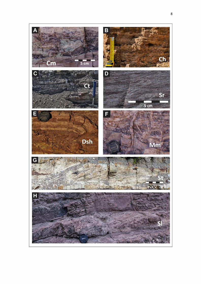
Intraformational conglomerates (A) are composed of muddy intraclasts in a sandy matrix with massive structure (Cm), high-angle cross-stratification (Ct) or horizontal stratification (Ch) (Fig. 3A, 3B and 3C). These facies are related to erosion, short-term transport and re-deposition of consolidated mud during high-energy flood events.
Sandstones with structures associated with deposition from upper flow regime conditions (B) comprise medium- to fine-grained, moderately sorted sandstones with horizontal lamination and parting lineation (Sh), low-angle cross bedding with common symmetrical form sets and parting lineation (Sl), sigmoidal cross bedding (Ss), and moderate-angle cross bedding (Sc). This assemblage of structures is associated with upper-stage plane bed, antidune migration, chute-and-pool migration and cyclic step migration respectively (Fig. 3G, 3I, 3J, 3L and 3M). This facies category records unidirectional shallow flow conditions associated with high-energy unchannelized floods that were subject to rapid deceleration (Power, 1961; Hand et al., 1969; Bridge, 2003; Fielding, 2006; Cartigny et al., 2014; Lowe & Arnott 2016).
Sandstones with structures associated with lower flow regime conditions (C) comprise medium-to fine-grained, moderately sorted sandstones with small-scale cross lamination associated with current ripple migration (Sr) or high-angle cross stratification associated with migration of subaqueous 3D dunes (St) (Fig. 3D and 3F). These structures represent conditions of lower flow regime in unidirectional flows; cross-stratification is associated with a greater water depth and commonly a degree of channel confinement that favours the development and stabilization of dunes on the channel bed (Southard and Boguchwal, 1990; Bridge, 2003; Collinson & Mountney, 2019).

7
Table 1: Summary of observed lithofacies in the Loncopué outcrop of the Tordillo Formation.
Facies Code Description Interpretation A
Intr
afo
rma
tio
na
l co
ng
lom
era
tes
Horizontally
bedded
intraformational
conglomerate
Ch
Horizontally bedded, matrix or clast-
supported with sub-rounded siltstone
and mudstone clasts. Matrix of fine
grained sandstone.
Eroded mud transported and re-deposited by
high-energy, turbulent unidirectional flows
during plane bed migration, associated with
channel lags.
Cross bedded
intraformational
conglomerate
Ct
High-angle cross bedded, clast-supported
with sub-rounded siltstone and mudstone
clasts. Matrix of fine and medium grained
sandstone.
Eroded mud transported and re-deposited by
high energy, turbulent unidirectional flows
during migration of 3D dunes, associated with
channel lags.
Massive
intraformational
conglomerate
Cm
Massive, matrix or clast-supported with
sub-rounded siltstone and mudstone
clasts. Matrix of fine and medium grained
sandstone.
Eroded mud transported and re-deposited
quickly by high-energy, turbulent unidirectional
flows, associated with channel lags.
B
Sa
nd
sto
ne
s (U
FR
)
Horizontally
laminated
sandstone
Sh
Fine to medium-grained, moderately
sorted. Horizontal lamination, associated
with parting lineation on bed surfaces.
Upper-stage plane bed formed in upper flow
regime near critical (Fr1) unidirectional flow,
mostly associated with unchannelized flows.
Low-angle cross
laminated
sandstone
Sl
Fine grained, moderately sorted. Low
angle (<10°) lenticular cross-laminated
sets; common symmetrical formsets.
Laminae are arranged in backsets.
Antidune migration formed under standing and
breaking surface waves in upper flow regime
unidirectional flows. Local preservation of
symmetrical form sets suggests high rates of
aggradation. Mostly associated with
unchannelized flows.
Sigmoidal cross
laminated
sandstone
Ss
Fine to medium grained, moderately
sorted. Low to high angle (5-15º),
sigmoidal scour filling cross laminated
sets with parting lineation on bed
surfaces. Laminae are arranged in
backsets.
Chute and pool migration formed under a
temporary hydraulic jump in a localized scour,
under high-velocity and shallow supercritical
flows. Associated with non-channelized or
poorly channelized flows.
Moderate-angle
cross laminated
sandstone
Sc
Fine to medium grained, moderately
sorted. Moderate-angle (15º) cross
laminated tabular sets bounded by
erosional surfaces. Laminae are arranged
in backsets.
Cyclic steps formed under migration of
stabilized and regularly spaced hydraulic jumps
in high-velocity and shallow supercritical
unidirectional flows.
C’
C
Sa
nd
sto
ne
s (L
FR
) Current ripple
cross laminated
sandstone
Sr
Fine grained moderately sorted. Ripple
sets with subcritical and supercritical
climbing.
Current ripple migration under lower-flow
regime unidirectional flows, associated with
non-channelized or channelized flows.
High-angle cross
bedded
sandstone
St
Fine to medium grained, moderately
sorted. High angle (>15º) mostly planar
and minor trough cross-stratified sets up
to 0.3 m thick.
Subaqueous 3D dune migration under low
regime unidirectional flows associated with
channelized flows.
D
Sil
ty s
an
dst
on
es
Current-ripple
laminated silty
sandstone
DSr
Current ripple laminated silty sandstone.
Common features included soft
sedimentary deformation and
bioturbation.
Current ripple migration under lower-flow
regime unidirectional flows, associated mostly
with unconfined flows.
Horizontally
laminated silty
sandstone
DSh
Horizontally laminated silty sandstone.
Common features included soft
sedimentary deformation and
bioturbation.
Deposition of suspended load from decelerating
flows associated mostly with unconfined flows.
E
Mu
dd
y s
ilts
ton
es
Horizontally
laminated
muddy siltstone
Mh
Horizontally laminated siltstone or muddy
siltstone. Common features include sand-
filled desiccation cracks, and soft-
sediment deformation.
Deposition of suspended load from decelerating
flows.
Massive muddy
siltstone Mm
Massive siltstone or muddy siltstone.
Common features include sand-filled
desiccation cracks, bioturbation,
rhizoliths, and pedogenic structures.
Deposition of suspended load from decelerating
flows or ponded, still water conditions.
Associated with distal areas, with subsequent
subaerial exposure and development of
palaeosols.
8
9

10
Figure 3: Examples of lithofacies observed in the Loncopué outcrop of the Tordillo Formation. Intraformational conglomerates. A) Massive intraformational conglomerate (Cm). B) Horizontally bedded intraformational conglomerate (Ch). C) Cross bedded intraformational conglomerate (Ct). Lower flow regime sandstones. D) Current-ripple cross laminated sandstone (Sr) and G) High-angle cross Laminated sandstone (St). Upper flow regime sandstones. I) Horizontally laminated sandstone (Sh). H) and J) Low-angle cross laminated sandstone (Sl). H) Sigmoidal cross laminated sandstone (Ss). L) Moderate-angle cross laminated sandstone (Sc). Silty sandstones. E) Horizontally laminated silty sandstone (DSh). Muddy siltstones. F) and M) Massive muddy siltstone (Mm).
Silty sandstones (D) comprise matrix-supported sandstones with a silty matrix, with current-ripple lamination (DSr) or horizontal lamination (DSh) (Fig. 3E). Common features in these facies also include soft-sediment deformation structures, such as load casts and convolute bedding/lamination; bioturbation is also present. These deposits record low-energy unidirectional flow conditions mostly associated with the falling (i.e. deceleration) stage of flood events.
Finally, muddy siltstones (E) include massive (Mm) (Fig. 3H and 3K) or horizontally laminated (Mh) facies that can exhibit sand-filled desiccation cracks, bioturbation, rhizoliths and pedogenic structures including blocky peds and carbonate glaebules. They are mostly associated with deposition of mud traction-load sand- and silt. Grade aggregates of mud sized particles (Wright & Marriot, 2007; Wakelin-King and Webb, 2007; Dasgupta et al., 2017).
The relative abundance of the different facies categories was calculated to quantify the relative importance of the different processes that acted in the system, and to demonstrate how these proportions vary laterally and vertically (Fig 4). Important observations arising from this analysis are as follows: (i) for this sector of the system, the proportion of fine-grained facies (silty sandstones and muddy siltstones) and coarser facies (all sandstones and intraformational conglomerates) is similar – 56% and 44%, respectively; (ii) there is a high preservation potential of sedimentary structures associated with upper flow regime conditions, which represent 65% of the sandstone facies; (iii) there is an upward increase in the proportion of fine-grained facies in the upper half of the succession.
5. BED TYPES
5.1 Markov chain analysis of facies transitions
Facies transitions were considered for those that occur between different beds and those that occur within a single bed, based on field observations of beds and their internal facies (“beds” sensu Campbell, 1967). Given that the aim of this analysis was to characterize types of beds, the facies transitions of interest herein are those that occur within the beds. Thus, the beds have been described and considered based on what categories of facies (A, B, C, D or E) are present internally and how they are ordered, following the methodology detailed below. A particular differentiation has been made on the basis of field observations. In cases where there is an upward vertical transition from sandstones associated with lower flow regime to sandstones associated with upper flow regime, St is the main structure associated with lower flow regime deposits. By contrast, in the sandstones where there is an upward vertical transition from sandstones associated with upper flow regime to sandstones associated with lower flow regime, Sr is the main structure associated with lower flow regime deposits. Given this, in figure 5, the letter C’, which corresponds to the facies St, is added to differentiate this facies from Sr, which is the facies that generally represents category C.
The most frequent within-bed observed facies transitions are as follows: (i) from silty sandstones to muddy siltstones (D-E); (ii) from sandstones associated with lower flow regime to muddy siltstones (C-E); (iii) from sandstones associated with upper flow regime to sandstones associated with lower flow regime (B-C); (iv) from sandstones associated with upper flow regime to muddy siltstones (B-E) (Fig. 4).

11
Based on the within-bed facies transitions and on the observations made in the field, seven different bed types are defined: ABE, BE, AC’BCE, ABCE, BCE, CE and DE (Fig. 5).
Based on the interpretation of the depositional processes associated with each facies categories, each type of bed was assigned to a position where it would be expected to appear within the depositional system, considering also the degree of channelization of the flow and the expected rates of deceleration (Fig. 6).
Figure 4: Relative frequencies of the five facies categories determined for the studied succession, for each log and by intervals. Stratigraphic intervals were defined according to the predominance of sandy and muddy facies.

12
Figure 5: Facies transitions between facies categories obtained from the analysis of Markov chains. A) Stacked bar charts of observed facies transitions. B) Diagram showing the significant facies transitions for the system and the values of transitions probabilities.

13
Figure 6: A) Bed types defined for the system based on the within-bed facies transitions. A: Intraformational conglomerates facies; B: Sandstones facies associated with upper-flow regime; C: Current ripple cross laminated sandstones; C’: High-angle cross bedded sandstones; D: Silty sandstone facies; E: Muddy silstone facies. According to field observations and the interpretation of facies transitions, each type of bed is located in a more proximal or distal position within the system, associated with a more or less channeled flow, and a more or less rapid deceleration of the flood. B) Examples of bed types. Facies codes are explained in Table 1.

14
5.2 Within-bed transitions: bed types
The fact that the order of occurrence of facies in the studied section is not random is fundamental since it gives sustenance and sense to move forward on the objective of building a predictive facies model. This approach is especially relevant where applied to ephemeral fluvial systems, for which discharges are infrequent and associated with short-duration, high-energy events.
In the studied section, each bed is interpreted as the record of one single flood event. Individual beds have a minimum thickness of 0.05 m and a maximum of 0.7 m, with an average thickness of 0.3 m in the beds that contain upper-flow-regime structures and 0.1 m in the beds that contain lower-flow-regime structures.
A notable point of the results is the appearance of within-bed transitions from sandstones associated with upper flow regime to muddy siltstones (BE beds). Although, based on the Markov Chain analysis, this did not prove to be a significant transition for the entire sedimentary succession, it is common to find this facies transition in beds of the upper sector of non-channelized sandy bodies (see 6.1.3: Sandy lobe deposits). This transition implies that, during the falling stage of high energy floods that were evidently subject to rapid deceleration, sandy bedforms of the lower flow regime do not readily develop (Fielding, 2006; Fielding et al., 2018).
The AC´BCE bed type is associated with more proximal ‘on-axis’ sectors, with a certain degree of channel confinement that allowed the development of intra-formational conglomerates and dunes in the streambed, and with a gradual deceleration of the flow associated with a flood event, as evidenced by the lower-stage facies at the top of such beds (Fig 6). The C’-B transition is associated with a reduction in flow depth when the discharge began to decrease, with the consequent flow acceleration, before the final stage of deceleration represented by facies C and E.
With a lower degree of confinement, beds vary in a similar manner to that proposed by Bridge (2003), from ABCE to E (Fig. 6). However, associated with relatively shallow flows, upper flow regime bedforms will develop instead of dunes, and the preservation of lower stage sandy facies will depend on the rate of flood deceleration. On this basis, shallow high-velocity flows with rapid deceleration will result in ABE or BE bed types; whereas shallow high-velocity flows with gradual deceleration will result in the BCE bed type (Fielding, 2006; Fielding et al., 2018). From these interpretations, it is evident that two main types of floods apparently occurred with a similar frequency in the system: floods that experienced gradual flow deceleration and floods with a more abrupt flow deceleration.
6. ARCHITECTURAL ELEMENTS
6.1 Architectural elements
Five different architectural elements have been defined in terms of their external geometry, scale, and proportions of bed types (Fig. 7); each characterised by predictable vertical and lateral facies successions. Architectural elements are classified into two groups: non-channelized and channelized. Examples of the former type are most common in this study.
Non-channelized architectural elements
6.1.1 Fine-grained deposits
Description: Fine-grained intervals are between 0.3 and 5 m thick and extend laterally for hundreds of metres to at least 1500 m (Fig. 7A). These element types are mostly represented by the E bed type, with common development of desiccation cracks, palaeosols, and rhizoliths. These intervals usually have reddish and brownish colourations, and intercalations of sandy or silty beds

15
with ripple cross lamination are common (mostly CE and DE bed types). Sandy deposits represent less than 15% of these architectural elements.
Interpretation: This element type is interpreted to record sedimentation via deposition of mud traction-load sand- and silt-grade aggregates of mud-sized particles that, through later compaction, were restructured into a mudstone texture (Wright & Marriot, 2007; Wakelin-King & Webb, 2007; Dasgupta et al., 2017). Desiccation cracks, pedogenic structures and rhizoliths suggest frequent subaerial exposure, and reddish colours indicate oxidizing conditions. Therefore, periods of non-deposition are interpreted. Episodic unidirectional flows are interpreted to be responsible for deposition of sandstone on silty sandstone beds.
Figure 7: Architectural elements and constituent bed types and facies observed in the studied sedimentary succession. Architectural elements A to C represent unconfined deposits and D and E channelized deposits.

16
6.1.2 Silty lobe deposits
Description: These elements include silty-sandstone bodies that may have an external tabular or lenticular geometry with flat bases and flat or convex tops (Fig. 7B). The thickness of each silty-sandstone body varies between 1 and 3 metres. Internally, these intervals are composite bodies formed by several (1 to 15) units (strata), each from 0.05 to 0.7 m thick. Each stratum is composed of one or more (generally up to 3) BCE, CE, DE or E bed types. Laterally each of the beds that constitute a single stratum becomes thinner, grading to a single thin sandstone bed (BCE and CE bed types) that passes transitionally to finer-grained facies (DE bed type) and ultimately transitioning to fine-grained deposits (E bed type). These architectural elements contain up to 40% of sandstone deposits.
Interpretation: The composite silty-sandstone bodies are interpreted to represent the accumulation in the off-axis zone of terminal lobe deposits (Saez et al., 2007; Fisher et al., 2008; Weissman et al., 2013). These elements may include crevasse splays deposits, considering that some studies on modern systems have shown that, towards the terminal sector of active and abandoned rivers, crevasse splays form amalgamated thin-bedded sand sheets which merge with the terminal splay sand of the river (Donselaar et al., 2013; Van Toorenenburg et al., 2018; Burns et al., 2017, 2019). The cross-sectional transition from the sandy axis sector to the silty off-axis sector of the lobe is not clear-cut (Figs. 8). This observation reflects the fact that the sedimentological distinction between the axis and off-axis sector is based on the change from bedload-dominated deposition to suspended load-dominated deposition as sheetfloods decelerate (Fisher et al., 2008). Even so, in off-axis sectors there is still evidence of tractional bedload deposition, such as the common presence of tractional structures like ripple cross lamination in the BCE and CE bed types.
6.1.3 Sandy lobe deposits
Description: These elements comprise sandstone bodies with an external tabular or lenticular geometry, flat bases and flat or convex tops, which alternate with intervals of fine-grained deposits (Fig. 7C). The thickness of each sandstone body varies between 1 and 4 metres. This element type has a low proportion of fine-grained sediment (<20%). Internally, these sandstone bodies are composite, formed by 1 to 5 individual beds, each ranging from 0.3 to 1 m thick, stacked in upward-thickening fashion (Fig. 8). In turn, each stratum is composed of one or more (up to 4) beds. Strata are composed, from bottom to top, by CE then BCE, and BE or ABE type beds (Fig. 7C and 8).
Detailed lateral mapping of the internal components of sandstone bodies has shown that lateral thickness trends in the internal strata can provide evidence of compensational stacking (Gulliford et al., 2017), and that the lateral termination of these bodies is given by the gradual transition to silty and then muddy deposits (Figs. 8, 9 and 10). These architectural elements contain up to 85% sandstone deposits.
Interpretation: The sandy lobes are interpreted as the preserved deposits of fluvial terminal lobes in the medial to distal zone of a terminal fluvial system. Given that sandy lobe deposits typically transition laterally to silty deposits, this architectural element most likely represents the axial sector of the lobes (Fisher et al., 2008; Weismann et al., 2013). In this zone, breakdown of channels causes the streamflow to be released from confinement, and the dominant flows become unconfined (North & Davidson, 2012). Each terminal lobe is composed of multiple lobe elements (internal strata), and a lobe element consist of multiple beds that represent single flood-related depositional events (Gulliford et al., 2017).
Lobe elements are therefore interpreted as the deposits of one or more accumulated depositional events (beds) with generally vertical stacking, but where beds are arranged in a compensational way. Compensation suggests avulsion (through the ‘incisional avulsion’ mechanism, sensu Mohrig et al., 2000) of the small-scale distributive channels feeding the lobes, with flows forced towards topographic depressions (Buehler et al., 2011; Weissmann et al., 2013). Part of these

17
deposits could also represent crevasse splays, although a distinction between terminal and crevasse splays is rendered difficult by the fact that, distally, crevasse splays form amalgamated deposits which merge with the terminal lobe deposits (Donselaar et al., 2013; Li and Bristow, 2014; Van Toorenenburg, 2018; Van Toorenenburg et al., 2018).
Considering the types of beds and the facies that compose the different sandy lobe elements (Fig. 4C), it appears that they most likely record an upward increase in the energy of the flows. This, together with the upward increase in lobe-element thickness, can be interpreted as evidence of terminal lobe progradation (Weismann et al., 2013; McKie et al., 2014).
Figure 8: Hierarchical scheme for sandy and silty lobe deposits. Flow direction is toward viewer, so scheme and photograph sections are across flow. See Table 1 for facies codes. A) Hierarchical scheme and lateral variations of bed types and internal facies. B) Outcrop photograph showing two sandy lobes with their lobe elements, and the fine-grained deposits that separate them.
Channelized architectural elements
6.1.4 Complex sheets
Description These elements comprise sandstone bodies up to 4.5 m thick with a very noticeable erosional lower boundary. Their external geometry is tabular to lenticular at outcrop scale, but they are internally composed of lenticular storeys each up to 1.5 m thick and each with an erosional lower boundary (Fig. 7D). Storeys are mainly composed of the AC’BCE bed type. No internal arrangements or trends in thickness have been observed. These architectural elements comprise up to 85% of sandstone deposits.

18
Interpretation: Complex sheets are interpreted as the record of fluvial, low-sinuosity channel fills where bedload was primarily transported as three-dimensional dunes at the bottom of the channels and without the development of major cross-channel or marginal bars (Veiga et al., 2007). The amount of lateral amalgamation of these units suggests the development of mobile channels that wandered across an alluvial plain, probably with a pattern of multiple shallow channels, leading to limited preservation of fine-grained overbank deposits (Veiga et al., 2007).
The abundant plane-bedded and current ripple-laminated facies, in association with scour fills and intraformational conglomerates (bed types AC’BCE), indicate shallow, high-velocity, waning flows which undertook repeated scouring and erosion. These features are typical of ephemeral flood processes (cf. Fielding, 2006; McKie, 2014).
6.1.5 Complex Ribbons
Description These elements comprise sandstone bodies up to 6 m thick with a lenticular external geometry and an erosional basal boundary (Fig. 7E). The fills include large-scale inclined surfaces that dip between 10° and 20° in cross-section and which define inclined sets of AC’BCE bed types, with a particularly high abundance of rip-up clasts on the basal surfaces of storeys. These architectural elements have up to 75% of sandstone deposits and a significant proportion of fine-grained sediment in the form of muddy intraclasts.
Interpretation Complex ribbons are interpreted as the record of laterally stacked fluvial-channel deposits, which represent the most proximal architectural elements of the sedimentary succession. The stacking results from two main processes: channel migration and avulsion. Migration occurred through gradual erosion since no lateral accretion surfaces have been observed. As channels commenced their abandonment phase, fluctuating, shallow, high-energy discharge resulted in preservation of sandy horizontally laminated facies (Holbrook, 2001). The vertically isolated nature of these sandstone bodies, together with evidence of rapid cut and fill, suggest that these fluvial systems did not form established channel belts and instead comprised discrete ribbons prone to sediment plugging and local avulsion (cf. McKie, 2014; Banham & Mountney, 2014).
6.2 Larger-scale architecture: lateral and vertical relations between architectural elements
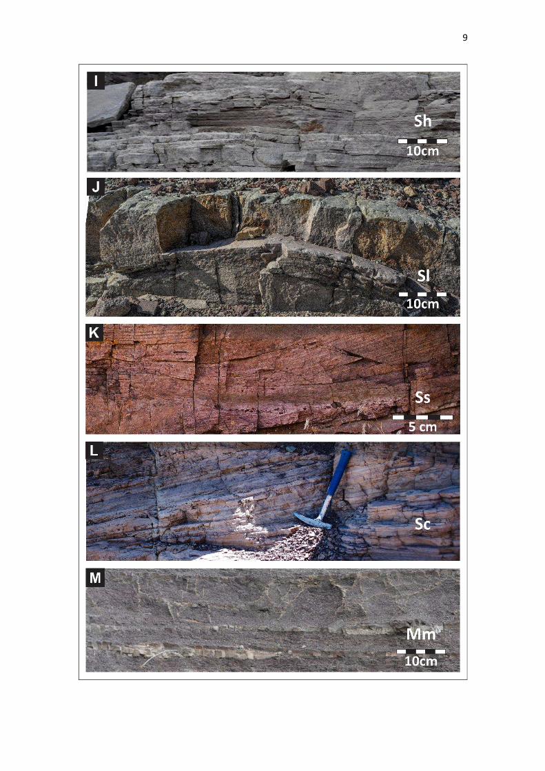
The lateral relations between architectural elements can be described in detail given the nature of the outcrop, and its orientation perpendicular to the direction of the palaeoflow. The sandy lobe deposits identified in this succession gradually pass laterally to silty lobe deposits. This lateral transition to finer deposits continues until there is an interdigitation with the finest-grained deposits. The total lateral extent of the lobe deposits, including their sand-prone central axial part and their silt-prone off-axis part that grades to fine-grained deposits, can reach a maximum of 1.2 km, although such direct measurements are limited by the size of the outcrop in some cases.
Through this transition, the degree of amalgamation of the internal components of lobe deposits varies laterally, decreasing towards the lateral areas. The lateral terminations of the silty lobe deposits are also characterized by a thinning of the beds of which they are composed, and an increase in the thickness of the intercalated muddy intervals.
Vertically, the transition from lobe deposits (both sandy and silty) to fine-grained deposits is abrupt and through a sharp bounding surface.
The channel deposits (complex sheets and complex ribbons), by contrast, most commonly occur atop sand-prone lobe deposits across erosional bounding surfaces.

19
Figure 9: The internal arrangement of lobe elements within lobe deposits. A) Correlation panel of a sandy lobe deposit. B) Correlation panel showing the defined lobe elements. C) Thickness variation of lobe elements. For each lobe element, the location of maximum thickness is indicated by a black dot.
7. DEPOSITIONAL MODEL
7.1 Sub-environments
Throughout the studied sedimentary succession three different large-scale architectural styles can be recognized (Fig. 11). These differ with regard to the distribution and predominance of the previously described architectural elements. These styles can be interpreted as representing different spatial configurations of sub-environments.
7.1.1 Proximal sub-environment
The proximal sub-environment is characterized by channel-fill complexes (40%), which are represented by the high relative abundance of complex sheets (30%) and complex ribbons (10%). These elements represent high-energy, bedload-dominated, shallow channels that migrated over the alluvial plain (Fig. 11A). These sandstone bodies are interpreted as deposits of discrete channel belts that formed between avulsion events (e.g., Hubert & Hyde, 1982; Bridge &Lunt, 2006; Nichols & Fisher, 2007; Payenberg et al., 2011; Gulliford et al., 2014; Lowe & Arnott, 2016).
20
Figure 10: Example of lateral facies change from lobe element to fine grained deposits. Note that to the right there is a predominantly sandy interval. The sandy beds of the middle sector become silty and thin to the left and interdigitate with the fine-grained beds.

21
Figure 11: Outcrop expression of the different sub-environments and the architectural elements that characterize them. Fg: Fine grained deposits; SL: sandy lobe deposits; CS: complex sheets; CR: complex ribbons; SiL: Silty lobe deposits.
Other common architectural elements in this sub-environment are the sandy lobe deposits (9%), which are commonly incised in their upper part by overlying channel deposits. Collectively, the sandy lobe elements and the channelized elements represent the 49% of the proximal sub-environment deposits; fine-grained deposits constitute 51% of this sub-environment.
22
7.1.2 Medial sub-environment
The transition from the proximal to the medial sub-environment is marked by an increase in the preserved proportion of sandy unconfined deposits (44%), an increase in the proportion of fine-grained elements (56%), and by the absence of channel-fill deposits (Sadler & Kelly, 1993; Fisher et al., 2007; Nichols & Fisher, 2007). The medial sub-environment is characterized by unconfined sandy deposits, dominantly represented by sandy lobe architectural elements (30%), which laterally pass transitionally into silty lobe deposits (14%) (Fig. 11B). Sandstone intervals tend to occur in packages separated by 1 to 4 m-thick intervals of mudrock (fine-grained deposits) that exhibit relatively weakly developed pedogenic features.
7.1.3 Distal sub-environment
The distal reaches form the most distinctive elements of terminal fluvial systems. They are characterised by a high proportion of fine-grained facies and a low proportion of channel-fill elements (Hirst, 1991; Sadler & Kelly, 1993; Fisher et al., 2007; Nichols & Fisher, 2007; Cain & Mountney, 2009). In the analysed sedimentary succession, the distal sub-environment shows an increase in the abundance of silty lobe deposits (25%), a decrease in the occurrence of sandy lobe deposits (from 44% to 10%), and an increase in the occurrence of fine-grained deposits (from 56% to 65%) (Fig. 11C). Another distinctive feature is the occurrence of alternating greenish and reddish palaeosols.
7.2 Depositional environment
The detailed facies analysis reveals a high proportion of sedimentary facies associated with upper flow regime conditions: almost 30% of the total facies and more than 60% of the sandy facies (Fig. 4). The presence of this assemblage of structures in the system and their widespread preservation within several of the architectural element types (Fig. 3), implies a recurrence of unidirectional, supercritical (Fr> 1), shallow ( 0.1 m depth), high-velocity (> 0.8 m.s-1) flows; it also implies a fast aggradation rate (> 0.15 mm.s-1, as determined from the empirical relationships of Southard & Boguchwal, 1990 and Cartigny et al., 2014). In the fine-grained facies (muddy siltstones) associated with the channel-fill deposits, desiccation cracks, pedogenic structures, and root traces are common; these structures provide evidence for frequent episodes of subaerial exposure in the system.
The quantitative analysis of the facies transitions enabled the definition of the main facies successions of the beds (Fig. 5), where beds are interpreted as the deposits of individual flood events. These facies successions record the degree of channel confinement of the flow, the rate of deceleration of the flow, and provide an indication of the relative position in the system. The quantitative analysis demonstrates that floods with high intensity and which undertook rapid deceleration were significant in the system.
The different bed types are grouped into five unique larger-scale architectural elements (Fig. 7). The most common architectural units are the sandy lobe deposits. These are composite bodies that show a general progradational arrangement; they are formed by the compensational stacking of lobe elements, which are in turn composed of beds (Figs 8 and 9). After sandy lobe units, the second most common architectural elements are the fine-grained deposits (Fig. 7). The transition between these two architectural elements is abrupt vertically, but transitional laterally (Fig. 10). This lateral transition is expressed through a change from sand-prone facies in on-axis locations within a lobe to silt-prone facies in off-axis fringes of the lobe. At the lateral limits of the lobe, these silt deposits interdigitate with even finer-grained floodplain deposits (Fig. 8, 9 and 10).
Collectively, these relationships demonstrate the development of terminal lobes in a muddy alluvial plain located at the downstream end of a river where the flood waters spilled across the adjacent, non-channelized, alluvial surfaces (cf. Tooth, 2004). The relationships between the architectural units indicate that the sandy and silty lobe deposits represent distal and lateral, off-axis areas of the terminal lobes subject to subaerial exposure, and that the lobes shifted position laterally in response to the repeated avulsions of feeder channels present in more proximal

23
locations (Fig. 12); this is evidenced by the abrupt transition from lobe deposits (both sandy and silty) to fine-grained deposits through a sharp surface.
The most abundant channelized architectural element corresponds to complex sheets, which are themselves made up of multi-storey channel fills amalgamated together to form a composite body with tabular to lenticular external cross-sectional geometry (Fig. 6). These units are interpreted as the record of poorly channelized flows, associated with a network of laterally mobile distributive channels. The main feeder channels of the lobes are derived from these channels. The fact that the channel deposits appear at the top of the sandy lobe deposits is interpreted as evidence of progradation (Van Toorenenburg et al., 2016). The analysed succession is interpreted as the medial to distal sector of a fluvial system in which the rivers terminated in the alluvial plain without reaching another significant body of water.
Figure 12: Depositional model representative of the typical lateral and vertical sedimentary architecture observed. Palaeogeographical significance for boxes of lower, middle and upper intervals is depicted in Fig. 14.
7.3 Long-term evolution of the system
Lower interval
The lower interval is characterized by a marked predominance of sandy lobe architectural elements alternating with fine-grained deposits (Fig. 13). The lowermost sandy lobe that can be identified in all the profiles has an average thickness of 4 m, and a lateral continuity that can be followed across the entire studied outcrop (1.5 km). Its internal arrangement has been mapped in detail (Fig. 9).
The directly overlying interval is muddy (fine-grained deposit architectural element); its thickness is typically close to 1 m, but locally reaches 2.3 m. As is common for these architectural elements, desiccation cracks and pedogenic structures are present and they are interpreted as evidence of subaerial exposure. The reddish colour is interpreted as a product of oxidising processes. To the north, and over a distance of approximately 400 m, this deposit gradually transitions laterally to silty and then sandy lobe deposits, thereby demonstrating that these architectural element types (fine-grained deposits and lobe deposits) are coeval and laterally related in the system.
Above is another sandy interval (up to 7 m thick), interpreted as a sandy lobe deposit. This lobe element differs from the underlying one not only in that it is thicker, but also in that it contains a higher proportion of conglomerate facies. Furthermore, this lobe element shows increasing thickness in the lowermost 67% of the unit, passing from bed type BCE, to ABCE, and finally to

24
ABE. In the uppermost 33% of the element, only limited conglomerate facies are present, with beds being mostly of BE and BCE types. This is interpreted as the record of the progradation and abandonment of the lobe but might also be due to the way in which the lobe elements are spatially arranged within the succession.
The lower interval terminates at the top in a fine-grained architectural element that attains a maximum thickness of 9 m. The same evidence of subaerial exposure and oxidation described for the previous fine-grained deposit can be observed here. These deposits are interpreted to have accumulated distally from active channels, in response to avulsion of the feeder channel of the system, at a time when the main active lobes developed in another sector of the alluvial plain. This interval represents the medial sub-environment.
Middle interval
The middle interval is characterized by the appearance and high relative abundance of channel architectural elements (Fig. 13). It commences with a sandstone body which extends laterally across the entire outcrop and whose thickness reaches 8.5 m. In almost all the outcrop, the lower part of this body (itself ~2.5 m thick) corresponds to a sandy lobe deposit in which lobe elements are composed mostly of BCE layers. The rest of the sandstone body is represented by channel units, mainly complex sheet elements, which overlie the lobe through an erosional contact. Towards the middle part of the interval, complex ribbon architectural units are observed (Fig. 11).
Given the features of the complex sheet elements and the scale of the bodies, this interval is interpreted as the record of channel deposits associated with the network of apparent distributive channels (arising from successive river positions after avulsion), that fed the lobes located more in more distal parts of the system.
The upper half of the middle interval is represented mostly by fine-grained deposits, which are in places interrupted by complex sheet elements of limited lateral continuity (<600 m).
Channel units are present in the upper part of the interval and are interpreted as deposits of channels that reached the distal parts of the system during episodes of high discharge. This interval represents the proximal sub-environment.
Upper Interval
In the upper interval the architectural elements that predominate are the silty lobe deposits and the fine-grained deposits (Fig. 13). The lobe deposits present in this interval differ from those in the underlying intervals both in their scale and in their internal components. These deposits tend to be thinner (<3 m). By contrast, the lobe elements that compose them are formed by bed types BCE, CE and DE, as the proportion of silty sandstones facies is much higher than in lobe deposits located in lower parts of the succession. Laterally, over a distance of 200 to 300 m, these deposits gradually pass to fine-grained deposits.
The proportion of fine-grained deposits recorded in this interval is the highest of the entire succession (>65%). A distinctive feature of this part of the succession is the increase in the proportion of greenish palaeosols that alternate with the reddish ones.
Considering the facies, the bed types and the thicknesses of the lobe deposits, these are interpreted as deposits associated with the off-axis sectors of the terminal lobes. The greater abundance of fine-grained elements could be associated with a more distal position in the system, or to greater available accommodation. The colour banding in these deposits indicates alternation between oxidising and reducing conditions (Retallack, 1997; Fisher et al., 2007). This suggests that the water table in the distal system was subject to fluctuations, such that swampy soils were more frequent than in the lower intervals. This interval represents the distal sub-environment.

25
Figure 13: Outcrop expression of lower, middle and upper intervals and their different architectural styles. Succession is 100 m thick.
8. DISCUSSION
8.1 Temporal Evolution
Considering the depositional model interpreted for the system and the characteristics of the different intervals of the succession, an interpretation of the temporal evolution of the system can be attempted.
The lower interval represents the record of deposits of at least two different sandy terminal lobes in a muddy alluvial plain. The middle interval is interpreted as a record of another sandy lobe and of the network of distributive channels that fed it, followed by sandy deposits accumulated on an alluvial plain that was frequently reached by channelized and non-channelized flows. Finally, the upper interval, in which the fine-grained deposits are thicker and where only the most distal expression of the terminal lobes (distal sectors of the lobes, represented by silty lobe deposits) are present, is interpreted as the preserved expression of a more distal sector in the system, relative to the underlying two intervals (Fig. 14).
Following the vertical arrangement of the elements in the succession, a general progradation of facies belts is interpreted from the lower to the middle interval. This is evidenced by the increase in thickness, grain size and inferred flow-energy seen between the first and the second sandy lobe deposits. In turn, the channel elements at the top of the third lobe, corresponding to the middle interval, represent a more proximal sector in the system with respect to the previous lobes (Fig. 14). This would represent the moment of maximum progradation of the facies belts of the system. The upper interval represents a change to the most distal sector of the system recorded in the sequence. This is interpreted as a relatively sharp retrogradation of facies belts, which leads to the more distal deposits of terminal lobes being observed in the upper part of the succession (Fig. 14).
8.2 Controls
A terminal lobe represents a depositional area of the alluvial plain where deposition takes place at the mouth of a feeder channel between two avulsion events. Avulsion of the feeder channel located directly upstream of the distributive part of the system shifts the locus of deposition and acts to initiate construction of a new lobe elsewhere. Internally, each terminal lobe is formed by

26
lobe elements, which themselves are fed by smaller-scale channels with short inter-avulsion periods (for example in the order of 700 yr; Donselaar et al., 2017).
Figure 14: Temporal evolution of the system from basal to upper section. See text for explanation.
Up to this level of hierarchy, avulsions that change the positions of the lobes and lobe elements are likely considered to be controlled, on both scales, by the relief constructed by the previous deposits, and the consequent diversion of subsequent floods to a new, topographically lower position on the alluvial plain (Nichols & Fisher, 2007; Gulliford et al., 2014; Lowe & Arnott, 2016); ‘incisional avulsion’ sensu Mohrig et al. (2000) is interpreted to have taken place. River avulsion tends to take place when two conditions are met: river super-elevation above the floodplain caused by channel aggradation, and a trigger (such as levee breakthrough during major flood events) that causes the abrupt abandonment of the channel (Mohrig et al., 2000). At higher levels in a stratigraphic hierarchy of elements, allogenic controls probably become progressively more dominant.
The progradation of the system, as represented by the deposits at the top of the middle interval (or at least to the top of the complex sheet units in the uppermost part of a sandy lobe deposit) is also considered to be an intrinsic feature of this type of system (e.g., Tunbridge, 1984; Weissmann et al., 2013; Gulliford et al., 2014). The retrogradation of the system recorded in the upper interval, however, is likely related to extrinsic controls. It is most readily interpreted as the response to a

27
progressive increase in accommodation, which can be related either to an increase in subsidence and/or to a progressive rise in base level during the beginning of a marine transgression, which has been suggested for the time interval of the Tordillo Formation (Spalletti & Colombo Piñol, 2005; Spalleti & Veiga, 2007). In a regional study of the Tordillo Formation, Spalletti and Colombo Piñol (2005) interpreted the greenish colours that appear in the fine-grained distal deposits of this formation as a prelude to the widespread Vaca Muerta transgression, which would have caused longer periods of elevated water table. An alternative interpretation could be a larger-scale avulsion taking place at a node located more proximally, causing the river and associated lobes to shift laterally to a different position by compensational stacking, and being expressed in the 2D cross-section of the outcrop as a marked upward reduction in grain-size.
8.3 Hierarchical scheme and stacking patterns for terminal lobe elements
In previous studies, unconfined deposits and terminal lobes or terminal splays have been described for the terminal sector of terminal fluvial-fan systems (e.g. Fisher et al., 2008; McKie, 2014; Lowe & Arnott, 2016). However, neither their internal anatomy nor their relations with other elements has previously been studied in detail.
The hierarchy and internal architecture of the components of terminal lobes has been widely studied for the deposits of submarine sediment gravity flows (Prélat et al., 2010; Spychala et al., 2015; Spychala et al., 2017), but not for subaerial fluvial systems. In fact, despite different physical processes and ambient fluids, the basic physics seems to produce remarkably similar products between deep-water channel-lobe deposits and fluvial terminal-lobe deposits. In both cases, a hierarchy of depositional elements can be established based on the identification of bounding surfaces and units that can be identified and mapped in outcrop. Furthermore, in both cases, at lobe-element scale, stacking patterns demonstrate a small-scale shift in the maximum thickness of lobe deposits between successive elements (Groenenberg et al., 2010). Thus, the deposition of a lobe element occurs within relative topographic lows established by the deposition of older lobe elements. Lobe-element deposition can therefore be linked to autogenic compensation processes and migration or instability of small-scale distributive channels (Prélat et al., 2010). Changes in the position of distributary fluvial channels are driven by the depositional topography they build, and which determines the gradient advantage that will cause their avulsion. The processes and conditions controlling river avulsion are complex (e.g., Jones & Schumm, 1999; Mohrig et al., 2000) and their detailed consideration is beyond the scope of this study. However, evidence suggests that large fluctuations in discharge may promote channel instability and avulsion (Leier et al., 2005), that major floods often serve as avulsion-triggering events (Jones & Schumm, 1999; Mohrig et al., 2000), and that the avulsion took place through an ‘incisional avulsion’ style (Mohrig et al., 2000). Thus, the decrease in the along-channel gradient, coupled with the increase in the across-floodplain gradient, promotes the avulsion of the river through one of the crevasse channels (Mohrig et al., 2000. Donselaar et al., 2013).
In both submarine and fluvial terminal lobes, vertical thickness trends in beds and lobe elements (e.g. thickening and thinning upward trends) in limited datasets can be used as a tool for the interpretation of depositional setting, the prediction of sandstone distribution and the assessment of sand connectivity in a lobe deposit (Prélat et al., 2010). However, analysis of deposit thickness should be attempted with caution as lateral changes in thickness can occur at highly variable lateral distances. For this reason, it is essential to consider quantitative data of facies and beds types as a predictive tool of lateral variations in the architecture of the system. 8.4 Comparison with other terminal fluvial systems
The Tordillo Fm appears to be peculiar, when compared with other ancient and modern fluvial systems. On a facies scale, the studied succession is notable for the high degree of preservation of upper-flow-regime structures associated with high-energy shallow flows.
This characteristic has not been described as being so dominant in other terminal fluvial systems, such as the Ebro, the Rio Colorado and the Morrison Formation (Donselaar et al., 2013; Weissmann et al., 2013; Li & Bristow, 2015; Owen et al., 2015; Van Toorenenburg et al., 2016;

28
Van Toorenenburg et al., 2018), but has been generally recognized for systems with significant variations in discharge regimes (Fielding 2006; Fielding et al., 2009; Fielding et al., 2011; Plink-Björklund, 2015; Fielding et al., 2018; Colombera & Mountney, 2019).
The present succession does not record deposits of channels with a high degree of incision, nor of lateral or frontal accretion bar deposits, as have been described for other terminal systems (Donselaar et al., 2013; Owen et al., 2015; Van Toorenenburg et al., 2018).
Regarding the architecture of the middle to distal sector of the system, it is the first time that fluvial terminal-lobe deposits have been described in terms of their complex internal architecture, which displays evidence for compensational stacking and a thickening-upwards internal arrangement.
Recent works on modern systems has highlighted the significant role of crevasse splays in the flow dispersion towards the terminal zone of this systems (Donselaar et al., 2013; Van Toorenenburg et al., 2016; Van Toorenenburg et al., 2018). However, in this study it has not been possible to differentiate between crevasse splays and terminal-lobe deposits, probably due to how closely associated they are in the distal areas.
9. CONCLUSIONS
The medial to distal sector of the terminal zone of an ephemeral terminal fluvial system has been studied from a well-exposed outcrop of the Jurassic Tordillo Formation, Neuquén Basin, Argentina. Both confined and unconfined deposits associated with this sector of the system and the relationships between them have been characterized via a multi-scale analysis of facies, facies transitions, bed types, architectural elements, larger-scale architectural styles, and vertical stacking. The sedimentary succession is characterized by the predominance of sandy and silty terminal lobes, which can be shown to comprise composite bodies formed by lobe elements staked in a compensational way. In turn, this has allowed determination of how terminal lobe deposits are built and how such construction is expressed in their internal hierarchy. Moreover, it allows demonstration of their spatial and vertical relationship to feeder channels. On the basis of these data, the deposits of proximal, medial and distal sub-environments are identified and a general depositional model is proposed. Regarding the temporal evolution of the system, a facies-belt progradation is observed, whereby channelized architectural elements that represent the distributary channels that fed the lobes indicate the point of maximum progradation. A subsequent retrogradation of facies belts across the entire system is recognised.
This study demonstrates the complexity of the confined and unconfined sand-prone deposits that characterize the distal sector of terminal fluvial systems through a multi-scale characterization and interpretation of their deposits and processes. This is important for the architectural characterization of fluvial terminal-lobe deposits. This study details, for the first time, the internal hierarchy and arrangement of fluvial terminal lobes and documents their relationships with the other architectural elements that make up the system. Moreover, this work demonstrates facies and architectural relationships that arise in response to the highly avulsive nature of terminal fluvial systems settings.
Acknowledgements
MDC, MFI and GDV thank CONICET (Consejo Nacional de Investigaciones Científicas y Técnicas), Universidad Nacional de La Plata, and YPF S.A. for financial support of this project. MDC thanks the International Association of Sedimentologists (IAS) for providing financial support through the Postgraduate Grant Scheme. Thanks to David Hodgetts, University of Manchester, UK, for provision of an academic license for use of the VRGS software. MDC is grateful to the people of Loncopué for their attention during fieldwork, and to Daniela Funes and

29
Gastón Álvarez Trentini for their assistance with data collection. NPM and LC thank AkerBP, Areva (now Orano), BHPBilliton, Cairn India (Vedanta), ConocoPhillips, Chevron, Equinor, Murphy Oil, Nexen-CNOOC, Occidental, Petrotechnical Data Systems, Saudi Aramco, Shell, Tullow Oil, Woodside and YPF for their support of the Fluvial & Eolian Research Group (FRG-ERG) at the University of Leeds. LC has been supported by NERC (Catalyst Fund award NE/M007324/1; Follow-on Fund NE/N017218/1). The manuscript has benefitted from constructive comments made by reviewers M.E. Donselaar, S.S. Flint and G.J. Nichols, and Associate Editor M. Ghinassi. References
Banham, S.G. and Mountney, N.P. (2014) Climatic versus halokinetic control on sedimentation in a dryland fluvial succession: Triassic Moenkopi Formation, Utah, USA. Sedimentology, 61, 570-608.
Billi, P. (2007) Morphology and sediment dynamics of ephemeral stream terminal distributary systems in the Kobo Basin (northern Welo, Ethiopia). Geomorphology, 85, 98-113.
Bridge, J.S. (2003) Rivers and Floodplains: Forms, Processes, and Sedimentary Record. Blackwell, Oxford, 491 pp.
Bridge, J.S. (2006) Fluvial facies models: recent developments. In: Facies models revisited (Eds H.W. Posamentier, R.G. Walker), SEPM Spec. Publ., 84, 85-170.
Bridge, J.S. and Lunt, I.A. (2006) Depositional models in braided rivers. In: Braided Rivers: Process, Deposits, Ecology and Management (Eds G.H. Sambrook Smith, J.L. Best, C.S. Bristow and G.E. Petts), IAS Spec. Publ., 36, 11–50.
Buehler, H.A., Weissmann, G.S., Scuderi, L.A. and Hartley, A.J. (2011) Spatial and temporal evolution of an avulsion on the Taquari River distributive fluvial system from satellite image analysis. J. Sed. Res., 81, 630-640.
Burns, C.E., Mountney, N.P., Hodgson, D.M. and Colombera, L. (2017) Anatomy and dimensions of fluvial crevasse-splay deposits: examples from the Cretaceous Mesaverde Group, Utah. Sedimentary Geology, 351, 21-35.
Burns, C.E., Mountney, N.P., Hodgson, D.M. and Colombera, L. (2019) Stratigraphic architecture and hierarchy of fluvial overbank crevasse-splay deposits. Journal of the Geological
Society of London, 176, 629-649.
Cain, S.A. and Mountney, N.P. (2009) Spatial and temporal evolution of a terminal fluvial fan system: the Permian Organ Rock Formation, South‐east Utah, USA. Sedimentology, 56, 1774-1800.
Campbell, C.V. (1967) Lamina, Laminaset, bed and bedset. Sedimentology, 8, 7-26.
Cartigny, M.J.B, Ventra, D., Postma, G. and van Den Berg, J.H. (2014) Morphodynamics and sedimentary structures of bedforms under supercritical‐flow conditions: new insights from flume experiments. Sedimentology, 61, 712-748.
Collinson, J.D. and Mountney, N.P. (2019) Sedimentary Structures. Dunedin Academic Press, Edinburgh, Scotland, 340 pp.
Colombera, L. and Mountney, N.P. (2019). The lithofacies organization of fluvial channel deposits: A meta-analysis of modern rivers. Sed. Geol., 383, 16-40.
Colombera, L., Mountney, N.P. and McCaffrey, W.D. (2012) A relational database for the digitization of fluvial architecture: concepts and example applications. Petroleum Geoscience, 18, 129-140.

30
Dasgupta, S., Ghosh, P. and Gierlowski-Kordesch, E.H. (2017) A discontinuous ephemeral stream transporting mud aggregates in a continental rift basin: the Late Triassic Maleri Formation, India. J. Sed. Res., 87, 838-865.
Davis, J.C. (2002) Statistics and Data Analysis in Geology, 3rd edn. John Wiley & Sons, New York, NY, 638 pp. Digregorio, R.E., Gulisano, C.A., Gutierrez Pleimling, A.R. and Minitti, S.A. (1984) Esquema de la evolución geodinámica de la Cuenca Neuquina y sus implicancias paleogeográficas, pp. 147-162. In: Relatorio del IX Congreso Geológico Argentino, S. C. de Bariloche.
Donselaar, M.E., Gozalo, M.C. and Moyano, S. (2013) Avulsion processes at the terminus of low-gradient semi-arid fluvial systems: Lessons from the Rio Colorado, Altiplano endorheic basin, Bolivia. Sed. Geol., 283, 1-14.
Donselaar M.E., Cuevas Gonzalo, M.C. and Wallinga, J. (2017). Avulsion History of a Holocene Semi-arid River System - Outcrop Analogue for Thin-bedded Fluvial Reservoirs in the Rotliegend Feather Edge. In: 79th EAGE Conference and Exhibition 2017.
Fielding, C.R. (2006) Upper flow regime sheets, lenses and scour fills: extending the range of architectural elements for fluvial sediment bodies. Sed. Geol., 190, 227-240.
Fielding, C.R., Alexander J. and Allen J.P., (2018). The role of discharge variability in the formation and preservation of alluvial sediment bodies. Sed. Geol., 365, 1-20.
Fielding, C.R., Allen, J.P., Alexander, J. and Gibling, M.R. (2009). Facies model for fluvial systems in the seasonal tropics and subtropics. Geology, 37, 623-626.
Fielding, C.R., Allen, J.P., Alexander, J., Gibling, M.R., Rygel, M.C. and Calder, J.H. (2011). Fluvial systems and their deposits in hot, seasonal semiarid and subhumid settings: modern and ancient examples. In: From River to Rock Record: The preservation of fluvial sediments and their
subsequent interpretation (Eds SK Davidson, S Leleu, CP North), SEPM Spec. Publ., 97, pp. 89-111.
Fielding, C.R., Ashworth, P.J., Best, J.L., Prokocki, E.W. and Smith, G.H.S. (2012). Tributary, distributary and other fluvial patterns: What really represents the norm in the continental rock record? Sed. Geol., 261, 15-32.
Fisher, J.A., Krapf, C.B., Lang, S.C., Nichols, G.J. and Payenberg, T.H. (2008) Sedimentology and architecture of the Douglas Creek terminal splay, Lake Eyre, central Australia. Sedimentology, 55, 1915-1930.
Fisher, J.A., Nichols, G.J. and Waltham, D. (2007) Unconfined flow deposits in distal sectors of fluvial distributary systems: examples from the Miocene Luna and Huesca Systems, northern Spain. Sed. Geol., 195, 55-73.
Friend, P.F. (1978) Distinctive features of some ancient river systems. In: Fluvial Sedimentology (Ed. by A. D. Miall). Mem. Can. Soc. Petrol. Geol., 5, 531–542.
Garrido, A. (2010) Estratigrafía del Grupo Neuquén, Cretácico Superior de la Cuenca Neuquina (Argentina): nueva propuesta de ordenamiento litoestratigráfico. Revista del Museo Argentino de
Ciencias Naturales Nueva Serie 12, 121-177.
Groenenberg, R.M., Hodgson, D.M., Prelat, A., Luthi, S.M. and Flint, S.S. (2010). Flow–deposit interaction in submarine lobes: Insights from outcrop observations and realizations of a process-based numerical model. J. Sed. Res., 80, 252-267.
Gulliford, A.R, Flint, S.S. and Hodgson, D.M. (2014) Testing applicability of models of distributive fluvial systems or trunk rivers in ephemeral systems: reconstructing 3-D fluvial architecture in the Beaufort Group, South Africa. J. Sed. Res., 84, 1147-1169.
31
Gulliford, A.R., Flint, S.S. and Hodgson, D.M. (2017) Crevasse splay processes and deposits in an ancient distributive fluvial system: the lower Beaufort Group, South Africa. Sed. Geol., 358, 1-18.
Gulisano, C.A. and Gutierrez Pleiming, A.R. (1994) The Jurassic of the Neuquén Basin, a) Neuquén Province. Asoc. Geolog. Arg., Series E2, 111.
Hampton, B.A. and Horton, B.K. (2007) Sheetflow fluvial processes in a rapidly subsiding basin, Altiplano plateau, Bolivia. Sedimentology, 54, 1121-1147.
Hand, B.M., Wessel, J.M. and Hayes, M.O. (1969) Antidunes in the Mount Toby Conglomerate (Triassic), Massachusetts. J. Sed. Res., 39, 1310-1316.
Harper, C.W. Jr. (1984) Improved methods of facies sequence analysis. In: Facies Models (Ed. by R. G. Walker). Geoscience Canada Reprint Series, Geol. Assoc. Canada, Toronto. 1, 2nd ed, 11-13.
Hartley, A.J., Weissmann, G.S., Nichols, G.J. and Warwick, G.L. (2010) Large distributive fluvial systems: characteristics, distribution, and controls on development. J. Sed. Res., 80, 167-183.
Hirst, J.P.P. (1991) Variations in alluvial architecture across the Oligo-Miocene Huesca Fluvial System, Ebro Basin, Spain. In: The Three-Dimensional Facies Architecture of Terrigenous
Clastic Sediments and its Implications for Hydrocarbon Discovery and Recovery (Eds A.D. Miall and N. Tyler), Soc. Sed. Geol. (SEPM) Concepts Sedimentol. Palaeontol., 3, 111–121.
Holbrook, J. (2001) Origin, genetic interrelationships, and stratigraphy over the continuum of fluvial channel-form bounding surfaces: an illustration from middle Cretaceous strata, southeastern Colorado. Sed. Geol., 144, 179-222.
Hubert, J.F. and Hyde, M.G. (1982) Sheet‐flow deposits of graded beds and mudstones on an alluvial sandflat‐playa system: Upper Triassic Blomidon redbeds, St Mary's Bay, Nova Scotia. Sedimentology, 29, 457-474.
Jones, L.S. and Schumm, S.A., (1999) Causes of avulsion: an overview, In: Fluvial
Sedimentology VI (Eds N.D. Smith, and J. Rogers). IAS Spec. Publ., 28, 171–178.
Kelly, S.B. and Olsen, H. (1993) Terminal fans-A review with reference to Devonian Examples. Sed. Geol., 85, 339-374.
Kietzmann, D.A., Cuitiño, J.I., Medina, R.A. and Scasso, R.A. (2009) Análisis de cadenas de Markov y series de Fourier en una secuencia hemipelágica del Jurásico superior de la Península Antártica. Latin American Journal of Sedimentology and Basin Analysis, 16, 45-56.
Lang, S.C., Payenberg, T.H.D., Reilly, M.R.W., Hicks, T., Benson, J. and Kassan, J. (2004) Modern analogues for dryland sandy fluvial-lacustrine deltas and terminal splay reservoirs. The
APPEA Journal, 44, 329-356.
Leanza, H.A. (2003) Las sedimentitas huitrinianas y rayosianas (Cretácico inferior) en el ámbito central y meridional de la cuenca Neuquina, Argentina. Servicio Geológico Minero Argentino, Serie Contribuciones Técnicas - Geología 2:1-31. Buenos Aires.
Legarreta, L. and Uliana, M.A. (1991) Jurassic-Cretaceous marine oscillations and geometry of backarc basin fill, Central Argentine Andes. In: Sea level changes at active plate margins,
sedimentation, tectonics and eustasy (Ed D.I. Macdonald), IAS Spec. Publ., 12, 429-450.
Leier, A.L., DeCelles, P.G. and Pelletier, J.D. (2005) Mountains, monsoons, and megafans. Geology, 33, 289-292.
Li, J. and Bristow, C. S. (2015). Crevasse splay morphodynamics in a dryland river terminus: Río Colorado in Salar de Uyuni Bolivia. Quatern. Int., 377, 71-82.

32
Lowe, D.G. and Arnott, R.W.C. (2016) Composition and architecture of braided and sheetflood-dominated ephemeral fluvial strata in the Cambrian-Ordovician Postdam Group: a case example of the morphodynamics of Early Phanerozoic fluvial systems and climate change. J. Sed. Res., 86, 587-612.
Maretto, H., Carbone, O., Gazzera, C. and Schiuma, M. (2002) Los reservorios de la Formación Tordillo. In: Rocas Reservorio de las Cuencas Productivas Argentinas (Eds M. Schiuma, G. Hinterwimmer and G. Vergani), pp. 335-358. V Congreso de Exploración y Desarrollo de Hidrocarburos, Mar del Plata.
McKie, T., Rose, P.T.S., Hartley, A.J., Jones, D.W. and Armstrong, T.L. (2014) In: Tertiary
deep-marine reservoirs of the North Sea region: an introduction (Eds T. McKie, P. T. S. Rose, A. J. Hartley, D. W. Jones and T. L. Armstrong),J. Geol. Soc. London, Spec. Publ., 403, 1-16.
Miall, A.D. (1973) Markov chain analysis applied to an ancient alluvial plain succession. Sedimentology, 20, 347-364.
Mohrig, D., Heller, P.L., Paola, C. and Lyons W.L. (2000) Interpreting avulsion process from ancient alluvial sequences: Guadalope-Matarranya system (Northern Spain) and Wasatch formation (Western Colorado). Geol. Soc. of America Bull., 112, 1787-1803.
Nichols, G.J. and Fisher, J.A. (2007) Processes, facies and architecture of distributary fluvial system deposits. Sed. Geol., 195, 75-90.
Nichols, G.J. and Hirst, J.P.P. (1998) Alluvial fans and fluvial distributary systems, Oligo-Miocene, Northern Spain: contrasting processes and products. J. Sed. Res., 68, 879-889.
North, C.P. and Davidson, S.K. (2012) Unconfined alluvial flow processes: Recognition and interpretation of their deposits, and the significance for palaegeographic reconstruction. Earth Sci.
Rev., 111, 199-223.
North, C.P. and Warwick, G.L. (2007) Fluvial fans: myths, misconceptions, and the end of the terminal-fan model. J. Sed. Res., 77, 693-701.
Olsen, H. (1987) Ancient ephemeral stream deposits: a local terminal fan model from the Bunter Sandstone Formation (L. Triassic) in the Tønder-3, -4 and -5 wells, Denmark. In: Desert
Sediments: Ancient and Modern (Eds L. Frostick and I. Reid), Geol. Soc. Spec. Publ., 35, 69–86.
Owen, A., Nichols, G.J., Hartley, A.J., Weissmann, G.S. and Scuderi, L.A. (2015). Quantification of a distributive fluvial system: the Salt Wash DFS of the Morrison Formation, SW USA. J.
Sed. Res., 85, 544-561.
Parkash, B., Awasthi, A.K. and Gohain, K. (1983) Lithofacies of the Markanda terminal fan, Kurukshetra district, Haryana, India. In: Modern and Ancient Fluvial Systems (Eds J.D. Collinson and J. Lewin), Spec. Publ. Int. Assoc. Sedimentology, 6, 337-344.
Payenberg, T., Willis, B., Bracken, B., Posamentier, H.W., Pyrcz, M., Pusca, V. and Sullivan,
M.D. (2011) Revisiting the subsurface classification of fluvial sandbodies. American Association
of Petroleum Geologists. In: Annual Convention and Exhibition, Houston, Search and Discovery Article (Vol. 90124).
Plink-Björklund, P. (2015). Morphodynamics of rivers strongly affected by monsoon precipitation: review of depositional style and forcing factors. Sed. Geol., 323, 110-147.
Power, W.R. (1961) Backset beds in the Coso Formation, Inyo County, California. J. Sed.
Petrol., 31, 603-607.
Prélat, A., Hodgson, D.M. and Flint, S.S. (2009). Evolution, architecture and hierarchy of distributary deep‐water deposits: a high‐resolution outcrop investigation from the Permian Karoo Basin, South Africa. Sedimentology, 56, 2132-2154.

33
Prelat, A., Covault, J.A., Hodgson, D.M., Fildani, A. and Flint, S.S. (2010) Intrinsic controls on the range of volumes, morphologies, and dimensions of submarine lobes. Sed. Geol., 232, 66-76.
Purkis, S., Vlaswinkel, B. and Gracias, N. (2012) Vertical-to-lateral transitions among Cretaceous carbonate facies – a means to 3-D framework via Markov analysis. J. Sed. Res., 82, 232-243.
Retallack, G. J. (1997) Colour guide to paleosols. John Wiley & Sons Ltd.
Sáez, A., Anadón, P., Herrero, M.J. and Moscariello, A. (2007) Variable style of transition between Palaeogene fluvial fan and lacustrine systems, southern Pyrenean foreland, NE Spain. Sedimentology, 54, 367-390.
Sadler, S.P. and Kelly, S.B. (1993) Fluvial processes and cyclicity in terminal fan deposits: an example from the Late Devonian of southwest Ireland. Sed. Geol., 85, 375-386.
Sánchez, M. L., Gómez, M. J. and Heredia, S. (2006) Sedimentología y paleoambientes del Subgrupo Río Colorado (Cretácico Superior), Grupo Neuquén, en las bardas de la ciudad de Neuquén y alrededores. Rev. Asoc. Geol. Argentina, 61, 236-255.
Sánchez, M. L. and Asurmendi, E. (2015) Stratigraphy and sedimentology of the terminal fan of Candeleros Formation (Neuquén Group), Lower Cretaceous, Neuquén basin, provinces of Neuquen and Mendoza, Argentina. Andean Geology, 42, 329-348.
Southard, J.B. and Boguchwal, L.A. (1990) Bed configuration in steady unidirectional water flows. Parth 2. Synthesis of flume data. J. Sed. Petrol., 60, 658-679.
Spalletti, L.A., Arregui, C.D. and Veiga, G.D. (2011) La Formación Tordillo y equivalentes (Jurásico Tardío) en la Cuenca Neuquina. Relatorio del XVIII Congreso Geológico Argentino, Neuquén, 99-111.
Spalletti, L.A. and Colombo Piñol, F. (2005) From alluvial fan to playa: an Upper Jurassic ephemeral fluvial system, Neuquén Basin, Argentina. Gond. Res., 8, 363-383.
Spalletti, L.A. and Veiga, G.D. (2007) Variability of continental depositional systems during lowstand sedimentation: an example from the kimmeridgian of the Neuquén Basin, Argentina. Latin American Journal of Sedimentology and Basin Analysis, 14, 85-104.
Spychala, Y.T., Hodgson, D.M., Flint, S.S. and Mountney, N.P. (2015). Transient but pertinent: constraining the sedimentary architecture of submarine intraslope lobes using exhumed examples from the Karoo Basin, South Africa. Sed. Geol., 322, 67-81.
Spychala, Y.T., Hodgson, D.M., Prélat, A., Kane, I.A., Flint, S.S. and Mountney, N.P., (2017). Frontal and lateral submarine lobe fringes: comparing sedimentary facies, architecture and flow processes. J.Sed. Res., 87, 75-96.
Stipanicic, P.N. (1966). El Jurásico en Vega de la Veranada (Neuquén), el Oxfordense y el diastrofismo divesiano (Agassiz-Yaila) en Argentina. Rev. Asoc. Geol. Arg., 20, 403-478.
Tooth, S. (2000) Process, form and change in dryland rivers: a review of recent research. Earth
Sci. Rev., 51, 67-107.
Tooth, S. (2004) Floodout. In: Encyclopedia of Geomorphology (Ed. A.S. Goudie), Routledge, London, pp. 380-381.
Tooth, S. (2005) Splay formation along the lower reaches of ephemeral rivers on the Northern Plains of arid central Australia. J. Sed. Res., 75, 636-649.
Turnbridge, I.P. (1984) Facies model for a sandy ephemeral stream and clay playa complex; the Middle Devonian Trentishoe Formation of North Devon, UK. Sedimentology, 31, 697-715.

34
Van Toorenenburg, K.A., Donselaar, M.E., Noordijk, N.A. and Weltje, G.J. (2016) On the origin of crevasse-splay amalgamation in the Huesca fluvial fan (Ebro Basin, Spain): Implications for connectivity in low net-to-gross fluvial deposits. Sed. Geol., 343, 156-164.
Van Toorenenburg, K.A. (2018) The key role of crevasse splays in prograding river systems. Analysis of evolving floodplain accommodation and its implications for architecture and reservoir potential. Delft University of Technology. Doctoral thesis, Technische Universiteit Delft. 105 pp (unpublished).
Van Toorenenburg, K.A., Donselaar, M.E. and Weltje, G.J. (2018). The life cycle of crevasse splays as a key mechanism in the aggradation of alluvial ridges and river avulsion. Earth Surf.
Proc. Land., 43, 2409-2420.
Veiga, G.D., Spalletti, L.A. and Flint, S.S. (2007) Anatomy of a fluvial lowstand wedge: the Avilé Member of the Agrio Formation (Hauterivian) in central Neuquén Basin (northwest Neuquén province), Argentina. In: Sedimentary Environments, Processes and Basins. A Tribute
to Peter Friend (Eds G. Nichols, E. Williams and C. Paola), IAS Spec. Publ., 38, 341-365.
Vergani, G.D., Tankard, A.J., Belotti, H.J. and Welsink, H.J. (1995) Tectonic evolution and paleogeography of the Neuquén Basin, Argentina. Petroleum Basins of South América. AAPG
Mem., 62, 383-402.
Wakelin-King, G.A., and Webb, J.A. (2007) Threshold-dominated fluvial styles in an arid-zone mud-aggregate river: the uplands of Fowlers Creek, Australia. Geomorphology, 85, 114-127.
Weissmann, G. S., Hartley, A. J., Nichols, G. J., Scuderi, L. A., Olson, M., Buehler, H. and
Banteah, R. (2010) Fluvial form in modern continental sedimentary basins: distributive fluvial systems. Geology, 38, 39-42.
Weissmann, G.S., Hartley, A.J., Scuderi, L.A., Nichols, G.J., Davidson, S.K., Owen, A., Atchley, S.C., Bhattacharya, P., Chakraborty, T., Ghosh, P., Nortdt, L.C., Michel, L. and
Tabor, N.J. (2013) In: Prograding distributive fluvial systems—geomorphic models and ancient
examples (Eds S.G. Driese, L.C. Nordt), SEPM Spec. Publ., 104, 131-147.
Wright, V.P. and Marriott, S.B. (2007) The dangers of taking mud for granted: lessons from Lower Old Red Sandstone dryland river systems of South Wales. Sed. Geol., 195, 91-100.