Embed Size (px)
Citation preview

TECHNICAL UNIVERSITY MALAYSIA MALACCA
Analysis Of The Influence Of Electrical Discharge Machine Die Sinking Parameters On Material
Removal Rate Of Mild Steel
Thesis submitted in accordance with the requirements of the Technical University Malaysia Malacca for the Degree of Bachelor of Engineering (Honors)
Manufacturing (Process)
By
Ahmad Syirwan Adli Bin Hamzah
Faculty of Manufacturing Engineering APRIL 2007

UTeM Library (Pind.1/2005)
SULIT
TERHAD
TIDAK TERHAD
(Mengandungi maklumat yang berdarjah keselamatan atau kepentingan Malaysia yang termaktub di dalam
AKTA RAHSIA RASMI 1972)
(Mengandungi maklumat TERHAD yang telah ditentukan
oleh organisasi/badan di mana penyelidikan dijalankan)
(TANDATANGAN PENULIS)
Alamat Tetap: 30A JALAN APOLLO TIMUR
96000 SIBU
SARAWAK
Tarikh: _______________________
Disahkan oleh:
(TANDATANGAN PENYELIA)
Cop Rasmi:
Tarikh: _______________________
* Tesis dimaksudkan sebagai tesis bagi Ijazah Doktor Falsafah dan Sarjana secara penyelidikan, atau disertasi bagi pengajian secara kerja kursus dan penyelidikan, atau Laporan Projek Sarjana Muda (PSM). ** Jika tesis ini SULIT atau TERHAD, sila lampirkan surat daripada pihak berkuasa/organisasi berkenaan dengan menyatakan sekali sebab dan tempoh tesis ini perlu dikelaskan sebagai SULIT atau TERHAD.
BORANG PENGESAHAN STATUS TESIS*
UNIVERSITI TEKNIKAL MALAYSIA MELAKA
JUDUL:
SESI PENGAJIAN: Saya _____________________________________________________________________ mengaku membenarkan tesis (PSM/Sarjana/Doktor Falsafah) ini disimpan di Perpustakaan Universiti Teknikal Malaysia Melaka (UteM) dengan syarat-syarat kegunaan seperti berikut:
1. Tesis adalah hak milik Universiti Teknikal Malaysia Melaka. 2. Perpustakaan Kolej Universiti Teknikal Kebangsaan Malaysia dibenarkan membuat
salinan untuk tujuan pengajian sahaja. 3. Perpustakaan dibenarkan membuat salinan tesis ini sebagai bahan pertukaran
antara institusi pengajian tinggi. 4. **Sila tandakan (√)
AHMAD SYIRWAN ADLI BIN HAMZAH
√
Analysis Of The Influence Of Electrical Discharge Machine Die Sinking Parameters On Material Removal Rate Of Mild Steel

DECLARATION
I hereby, declare this thesis entitled
“Analysis Of The Influence Of Electrical Discharge Machine Die Sinking Parameters
On Material Removal Rate Of Mild Steel” is the results of my own research except
as cited in the reference.
Signature : ………………………………………….
Author Name : …………………………………………
Date : …………………………………………
AHMAD SYIRWAN ADLI BIN HAMZAH
18 MAY 2007

i
ABSTRACT
This thesis discusses about the analysis of electrical discharge machine (EDM)
die sinking parameters on the material removal rates (MRR) of mild steel. Initially, five
important factors are identified as a factor influencing and affecting MRR. The factors
are electrical discharge peak current (IP), servo voltage (SV), main supply voltage (V),
servo speed (S) and jump speed (JS). Even though five parameters are considered
affecting MRR, it is significant to find which are affecting most. So, design of
experiment (DOE) method is used to predict the most affecting parameters. After DOE
analysis, it is found that only three major parameters plays a vital role in the material
removal rate. They are IP, SV and V respectively significant. Based on the significant
parameter, a mathematical model is constructed and developed. This design
mathematical model is used in the conducted experiment and hence applied to determine
the MRR of mild steel.

ii
DEDICATION
Specially dedicated to my beloved family.

iii
ACKNOWLEDGEMENTS
Alhamdullilah. Thanks to ALLAH S.W.T. that always give me enthusiasm in
completing my thesis. Thanks to Mr. Raja Izamshah Raja Abdullah for his guidance in
completing this thesis. I would like to thanks to my family especially my mother
Dayang Saadiah Bte Awang Basri and my father Hamzah Bin A.Beeran for their endless
support. Thanks to everyone who have been helping me in completing the thesis.
iv
TABLE OF CONTENTS
Abstract……………………………………………………………………………………i
Dedication………………………………………………………………………………...ii
Acknowledgements……………………………………………………………………...iii
Table of Contents………………………………………………………………………...iv
List of Figures…………………………………………………………………………...vii
List of Tables………………………………………………………………………….....ix
List of Abbreviation………………………………………………………………………x
1. INTRODUCTION
1.1 Background………………………………………………………………………...1
1.2 Problem Statement…………………………………………………………………2
1.3 Objectives………………………………………………………………………….3
1.4 Scope of Project……………………………………………………………………3
2. LITERATURE REVIEW
2.1 Introduction………………………………………………………………………...4
2.2 Machine……………………………………………………………………………5
2.3 Electrode…………………………………………………………………………...5
2.4 Tools and Its Properties
2.4.1 Graphite……………………………………………………………………….6
2.4.2 Copper………………………………………………………………………6-7
2.4.3 Copper Tungsten……………………………………………………………7-8
2.4.4 Aluminum…………………………………………………………………….8
2.5 Dielectric Fluid………………………..…………………………………………8-9
2.6 Material Removal Rate…………………………………………………………9-11
2.7 Height Gauge……………………………………………………………………..11
2.8 Jigs and Fixture…………………………………………………………………...12

v
2.9 SODICK LN2 / LQ Series………………………………………………………..12
2.9.1 Polarity, PL…………………………………………………………………...13
2.9.2 Electric Discharge Peak Current, IP………………………………………….13
2.9.3 Servo Voltage, SV………………………………………………………...13-14
2.9.4 Main Supply Voltage, V……………………………………….……………..14
2.9.5 Servo Speed, S….…………………………………………………………….15
2.9.6 Jump Speed, JS……………………………………………………………….16
2.10 Tool Offset……………………………………………………………………….17
2.11 Principal Working of EDM Die Sinking……………………………………..17-18
2.11.1 Physical Process………………………………………………………….18-20
3. METHODOLOGY
3.1 Introduction……………………………………………………………………….21
3.2 Design of Experiment
3.2.1 Phase 1: Define the Objective of Study.....................................................…...21
3.2.2 Phase 2: Develop the Cause-effect Diagram………………………………....22
3.2.3 Phase 3: Develop an experimental Array………………………………...22-23
3.2.4 Phase 4: Analysis of DOE……………………………………………………24
3.3 Process Planning
3.3.1 Machine……………………………………………………………………...24
3.3.2 Fixture………………………………………………………………………..25
3.3.3 Tool Selection………………………………………………………………..25
3.3.4 Check Sheet………………………………………………………………26-27
3.3.5 Machining Condition……………………………………………………..28-29
4. RESULTS AND ANALYSIS
4.1 Introduction……………………………………………………………………….30
4.2 Experiment Result…………………………………………………………….31-32
4.3 Analysis Design of Experiment……………………………………………….33-36
4.3.1 Reduced Model……………………………………………………………37-39

vi
4.3.2 Analysis of Variance (ANOVA)………………………………………….40-41
4.3.2 Mathematical Model……………………….....................................................42
5. DISCUSSION
5.1 Machining………………………………………………………………………..43-45
5.2 Step of Analysis MRR…………………………………………………………...45-47
5.3 Validation of Equation………………………………………………………………48
6. CONCLUSION……………………………………………………...………………49
REFERENCES………………………………………………..……………………50-51
APPENDICES
Appendix A Minitab Output for Significant and Not significant
Appendix B Minitab Output for ANOVA
Appendix C Programming Code output by machine
Appendix D Programming Code output by changing parameter

vii
LIST OF FIGURES
2.1 Material removing by EDM 5
2.2 The appearance of copper 7
2.3 The aluminum metal appearance 8
2.4 The voltage time diagram 10
2.5 Height gauge 11
2.6 Vise as clamping in machining 12
2.7 The characteristic of high SV and low setting SV 14
2.8 The process of how material is removed 18
2.9 Electrode and workpiece is energized 18
2.10 The ionized created 19
2.11 The spark giving heat to melt the work piece 19
2.12 The implosion of spark 19
2.13 The material is removed away from workpiece 20
3.1 The cause-effect diagram 22
3.2 Flow chart process planning 24
3.3 The dimension of electrode 25
3.4 The calibration gauge check sheet for height gauge 26
3.5 The result check sheet for checking dimensional electrode 26
3.6 The check sheet for result after machining 27
4.1 The graph significant and not significant of combination factors 33
4.2 The pareto chart effect of combination factors 34
4.3 The graph mean of MRR versus Factors 35
4.4 The factor interaction graph 36
4.5 The graph of reduced model 37
4.6 The interaction of three significant factors 38

viii
4.7 The cube plot of three significant factors 39
4.8 The residual plots of MRR 41
4.9 The output of coefficient value for coded and uncoded unit 42
5.1 The header conditions that created by machine 44
5.2 The header of alternative by changing all conditions 45

ix
LIST OF TABLE
2.1 Characteristic and properties of three type natural graphite 6
2.2 Servo voltage parameter 13
2.3 Servo speed characteristic 15
2.4 The characteristic voltage limit 15
2.5 Second digit of JS 16
2.6 First digit of JS 16
3.1 Design layout 23
3.2 Parameter setting 28
4.1 Design matrix of DOE with full factorial of five factors 30
4.2 The result obtain from the experiment 31

x
LIST OF ABBREVIATION
ANOVA - Analysis of Variance
CNC - Computer Numerical Control
DOE - Design of Experiment
EDM - Electrical Discharge Machine
IP - Electric Discharge Peak Current
JS - Jump Speed
MRR - Material Removal Rate
S - Servo Speed
SV - Servo Voltage
V - Main Supply Voltage

1
CHAPTER 1
INTRODUCTION
1.1 Background
Electrical discharge machining is a new technology adopted in advanced
machining process to remove the material part using electrode as cutting tool. The
tool materials that are commonly used are copper and graphite due to its wear
resistance. There are also other type of materials that can be used but not widely such
as copper tungsten, aluminum, tellurium copper, brass and tungsten carbide. The
main factor for choosing the electrode depends on good electrical conductivities. The
choice of electrode will firstly base on how easy the electrode can be machined to get
the desired shape. Second the electrode is chosen on it based own mechanical
properties that can long lasting of it wear mechanical properties. It means that the
electrode having lower melting point the tool wear rate will increase.
The working principle of EDM is to produce and generating spark and hence
to remove the material. The simplest way to understand the spark generating is the
same like the car lead acid batteries. It has a cathode and an anode. Connect one end
of the anode with a wire and the cathode end is free. By using wire that connected at
anode touch it to the cathode the spark will produce. After the spark has been
produce by the car lead acid there will be some amount of the end is been removed.
Where the anode is representing the electrode and the cathode is represent for the
work material. That is the basic EDM principle working. EDM does not need any
mechanical force to remove the material but it needs only the impulse of voltage and
ampere to remove the part material.
2
1.2 Problem Statement
Electrical discharge machining (EDM) has been used effectively in the
machining of hard, high strength and temperature resistant materials. Material is
removed by means of rapid and repetitive spark discharges across the gap between
the cutting tool and the work piece. In EDM, it is most important to select machining
parameter for achieving optimal machining. Usually, the desired machining
parameters are determined based on experience or handbook values. However this
dose not ensures that the selected machining parameter result in optimal or near
optimal machining performance for that particular electrical discharge machining and
environment. To solve this task in the present study, the Design of Experiment
(DOE) method is used as an efficient approach to determine the optimal machining
parameters in the electrical discharge machining process.
The electrical discharge machining removes work piece by an electrical
erosion process. The variations in the machining parameters such as the polarity,
servo speed, voltage, jump speed, peak current and servo voltage are greatly affect
the machining performance.
Through determining the effect of voltage and current the material removal
rate (MRR) will be change directly because it is simultaneously connected. By going
trough the analysis of the MRR it can decrease the cycle time and also can find the
cost estimation of the product. Effect of the using high rate MRR and low rate MRR
have to be determine either it will effect to the work material. The determination of
MRR is best for industry that used it for making mold and to remove the hard
conductivity material.

3
1.3 Objective
The objectives of this project are:
I. To determine the material removal rate (MRR) of mild steel using
graphite.
II. To find the most significant electrical discharge machining parameter
that influences the MRR.
1.4 Scope of Project
1. Understand the EDM Die Sinking process.
2. Machining implementation of mild steel with graphite electrode.
3. Determine MRR with different machining parameter.
4. Analyze the result with Design of Experiment (DOE).

4
CHAPTER 2
LITERATURE REVIEW
2.1 Introduction
Machine has a broad term to describe; machine is always describing as
equipment that helping man to done operation. Another term of describing machine
is a device that transmits energy to perform some task. Machine can also be
described as a man slave. Why it is call as a man slave? It is because the machine is
operating by mans instruction to complete the men task.
Machine has three basic categories. First categories machine is computer
numerical control (CNC) type machine. The second category is manual type machine
and a third category is semi automatic machine.
In manufacturing, machine is like a brother to the engineers and technician.
Machine is helping people to give high production. Machine that is popular among
the engineers is the machine that based on removal rates. This is because in
producing part it always comes from raw material then it comes a product. Some
kind of machine that based on removal rates is electro discharged machine (EDM),
turning machine and lathe machine. These are common machine in production.

5
2.2 Machine
Electro Discharge Machine is a process of machining that is using spark to
remove the material as shown in figure2.1. Figure2.1 shows the tool is not contacting
the workpiece to remove the material. The contact is happen between the dielectric to
produced spark. The spark can be control by length of the gap. The spark also can be
control with the current and the voltage of the EDM.
Figure2.1: Material removing by EDM
2.3 Electrode
Electrode is one of the important components in EDM die sinking. Electrode
is work as cutting tool. In machining process the cutting tool is need to be selected to
get the better result when machining. The electrode must have its own criteria to be
use in EDM machining. Firstly the electrode must be good conductivity of electrical
and heat. Next, the electrode must be easily machined to reduce the tooling cost. The
electrode must be highly wear rates so that the electrode will be long life. Tool is also
choose to there hardly decomposition too the other material. In early stage the
electrode is choose based on try and error to choose the material type.
The common material of tool is graphite, copper and copper-tungsten. This
material is choosing because the material is good conductivity of current then the
material is not easily decomposition to the workpiece.
6
2.4 Tools and Its Properties
2.4.1 Graphite
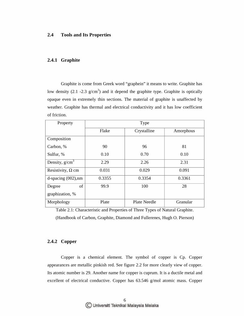
Graphite is come from Greek word “graphein” it means to write. Graphite has
low density (2.1 -2.3 g/cm3) and it depend the graphite type. Graphite is optically
opaque even in extremely thin sections. The material of graphite is unaffected by
weather. Graphite has thermal and electrical conductivity and it has low coefficient
of friction.
Type Property
Flake Crystalline Amorphous
Composition
Carbon, %
Sulfur, %
90
0.10
96
0.70
81
0.10
Density, g/cm3 2.29 2.26 2.31
Resistivity, Ω cm 0.031 0.029 0.091
d-spacing (002),nm 0.3355 0.3354 0.3361
Degree of
graphization, %
99.9 100 28
Morphology Plate Plate Needle Granular
Table 2.1: Characteristic and Properties of Three Types of Natural Graphite.
(Handbook of Carbon, Graphite, Diamond and Fullerenes, Hugh O. Pierson)
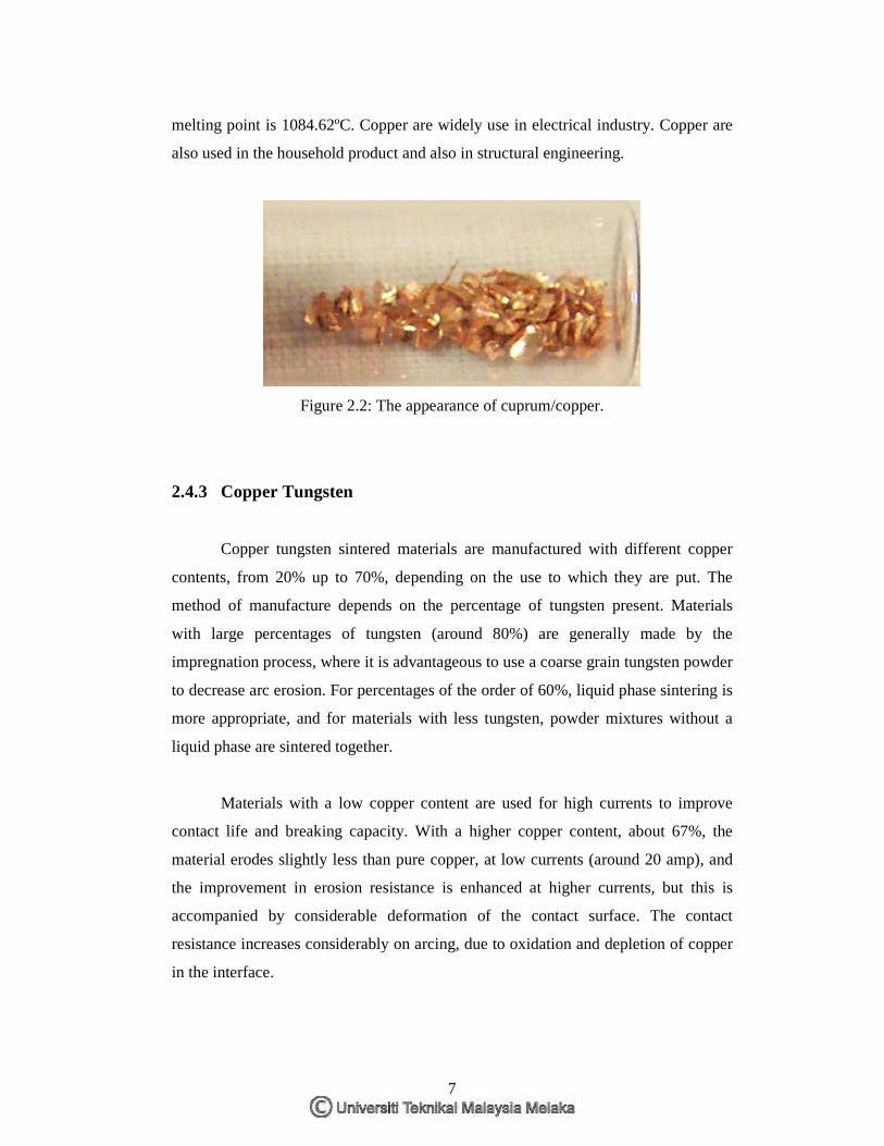
2.4.2 Copper
Copper is a chemical element. The symbol of copper is Cp. Copper
appearances are metallic pinkish red. See figure 2.2 for more clearly view of copper.
Its atomic number is 29. Another name for copper is cuprum. It is a ductile metal and
excellent of electrical conductive. Copper has 63.546 g/mol atomic mass. Copper
7
melting point is 1084.62ºC. Copper are widely use in electrical industry. Copper are
also used in the household product and also in structural engineering.
Figure 2.2: The appearance of cuprum/copper.
2.4.3 Copper Tungsten
Copper tungsten sintered materials are manufactured with different copper
contents, from 20% up to 70%, depending on the use to which they are put. The
method of manufacture depends on the percentage of tungsten present. Materials
with large percentages of tungsten (around 80%) are generally made by the
impregnation process, where it is advantageous to use a coarse grain tungsten powder
to decrease arc erosion. For percentages of the order of 60%, liquid phase sintering is
more appropriate, and for materials with less tungsten, powder mixtures without a
liquid phase are sintered together.
Materials with a low copper content are used for high currents to improve
contact life and breaking capacity. With a higher copper content, about 67%, the
material erodes slightly less than pure copper, at low currents (around 20 amp), and
the improvement in erosion resistance is enhanced at higher currents, but this is
accompanied by considerable deformation of the contact surface. The contact
resistance increases considerably on arcing, due to oxidation and depletion of copper
in the interface.

8
For larger contact forces, the static welding limit of copper-tungsten (60/40)
is very much higher than for any other material of this type, although at low contact
forces the hardness of the material produces very small metallic contact areas,
resulting in high contact resistance and low welding limit.
2.4.4 Aluminum
Aluminum is a group of chemical elements. The symbol for aluminum is Al.
Aluminum has atomic number 13. It is ductile and poor metal group. Aluminum
atomic mass is 26.9815386 g/mol. Aluminum melting point is 2519ºC. Aluminum
appearance is in silvery color. See figure2.3 for looking the aluminum appearance.
Figure 2.3: The aluminum metal appearance.
2.5 Dielectric Fluid
The dielectric fluid acts as an insulator between the electrode and the
workpiece. There are many dielectrics to choose based on the insulation properties of
the fluid. Air is not a very good insulator but it still can be used. Water is best. But
water has a few drawbacks. First, it causes rust to the workpiece or the electrode
itself. Second, the electrical discharge separates the water into pure hydrogen and
pure oxygen this element very explosive pair. The water can be as dielectric but it is
must-deionized water. A good compromise then is kerosene. No rust problem and no

9
dangerous gasses are produced with kerosene while the process is done between the
electrode and workpiece.
Dielectric functionally works as insulator until the potential is sufficiently
high. It also works as a flushing medium and carry away the debris in the gap and
lastly it is a cooling medium. (Kalpakjian, 2000)
2.6 Material Removing Rate MRR
There are three ways of expressing the MRR by the equation and each
equation is showing the different unit.
t
MMRR = ---------------------------------------------------------------------------equation 1
M= mass workpiece before machining – mass workpiece after machining
t = machining time
The second equation is:
Electrode area (in2) x Depth of cut (in) / Time of cut (min) -------------------equation 2
The third equation is:
MRR=Fc. Ie. Ue. ts / (ts + ti )---------------------------------------------------------equation 3
(Journal Of Material Processing Technology Y. Chen and S.M Mahadivan)
10
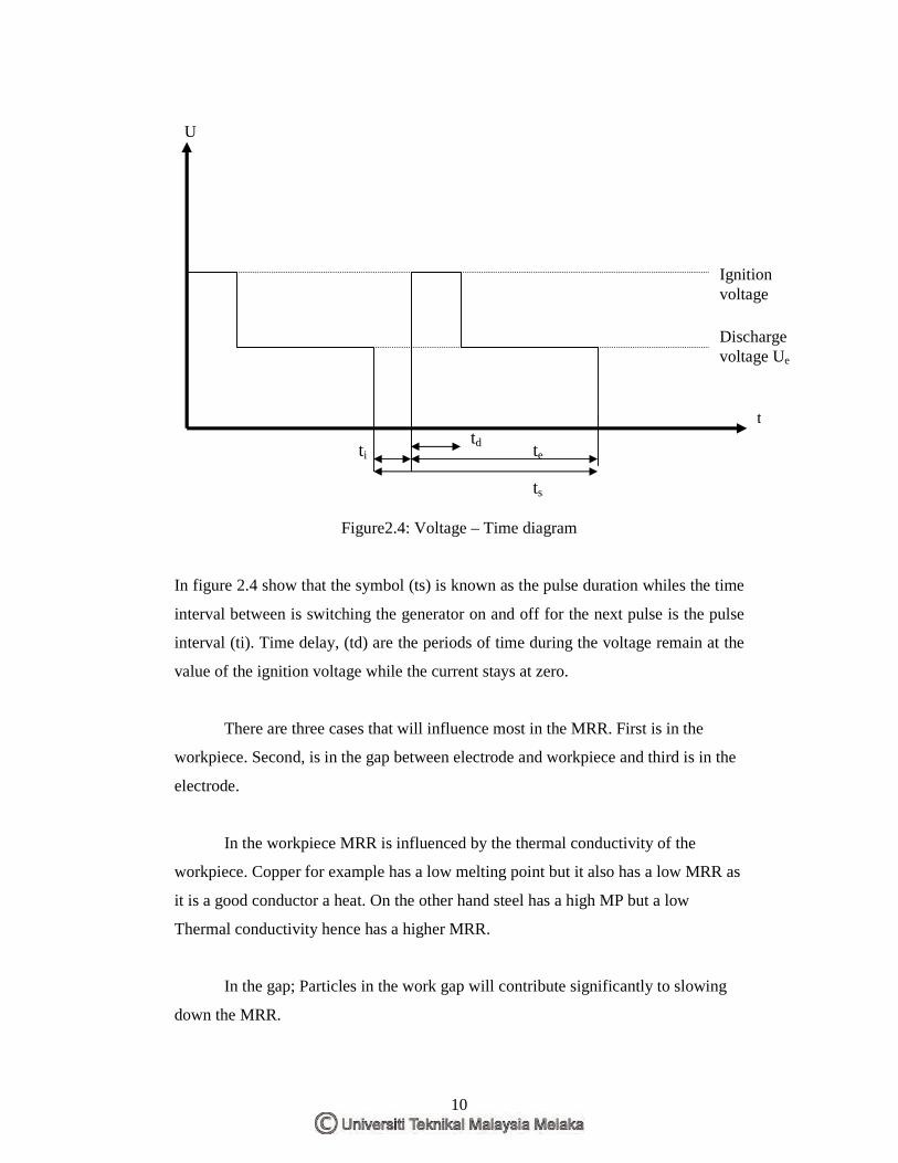
Figure2.4: Voltage – Time diagram
In figure 2.4 show that the symbol (ts) is known as the pulse duration whiles the time
interval between is switching the generator on and off for the next pulse is the pulse
interval (ti). Time delay, (td) are the periods of time during the voltage remain at the
value of the ignition voltage while the current stays at zero.
There are three cases that will influence most in the MRR. First is in the
workpiece. Second, is in the gap between electrode and workpiece and third is in the
electrode.
In the workpiece MRR is influenced by the thermal conductivity of the
workpiece. Copper for example has a low melting point but it also has a low MRR as
it is a good conductor a heat. On the other hand steel has a high MP but a low
Thermal conductivity hence has a higher MRR.
In the gap; Particles in the work gap will contribute significantly to slowing
down the MRR.
U
t
Ignition voltage
td
ts
te ti
Discharge voltage Ue