Embed Size (px)
Citation preview
Analysis of RC Building Frames for Seismic
Forces Using Different Types of Bracing Systems
Rishi Mishra
1 Dr. Abhay Sharma
2 Dr.
Vivek Garg
3
1M.Tech. Student, Structure Engineering, Department of Civil Engineering, MANIT, Bhopal (M.P.)
2Associate Professor, Department of Civil Engineering, MANIT, Bhopal (M.P.)
3Assitent Professor, Department of Civil Engineering, MANIT, Bhopal (M.P.)
Abstract- In this study, seismic analysis of high rise RC building frames have been carried out considering different types of bracing systems. Bracing systems is very efficient and unyielding lateral load resisting system. Bracing systems serves as one of the component in RC buildings for increasing stiffness and strength to guard buildings from the incidence caused by natural forces like earthquake force. In proposed problem G+ 10 story building frame is analysed for different bracing system under seismic loading. STADD-Pro software is used for analysis purpose. The results of various bracing systems (X Bracing, V Bracing, K Bracing, Inverted V Bracing, and Inverted K Bracing) are compared with bare frame model analysis to evaluate the effectiveness of a particular type of bracing system in order to control the lateral displacement and member forces in the frame. It is found that all the bracing systems control the lateral displacement of frame very effectively. However Inverted V bracing is found to be most economical.
KEYWORDS -- Seismic; Bracing system; moment; Shear force;
Storey displacement; storey drift; Inverted V Bracing, etc.
I. INTRODUCTION
Structures are built to facilitate the performance of various
activities connected with residence, office, education,
healthcare, sports and recreation transportation, storage,
power generation, etc. All the structures should sustain the
loads coming on them during their service life by
possessing adequate strength and also limit the deformation
by possessing enough stiffness. Strength of a structure
depends on characteristics of the material with which it
constructed and Stiffness depends upon the cross sectional
and geometrical property of the structure. Tall building or
multi-storied building defined as virtue of its height (more
than 30 m), is affected by lateral forces due to wind or
earthquake or both to an extent that they play an important
role in the structural design. Structural analysis deals with
the mechanism of regeneration of loads applied on the
system into local element force, using various theories and
theorems enunciated by eminent engineers and
investigators. It also deals with the computation of
deformations these members suffer under the action of
induced forces.
The essential work of members of framed structure is to transfers the gravity loads and lateral loads to the foundation of structure and then to the earth. The main loads comes in the structure is gravity loads consists dead load, live loads and some service loads. Beside this there is
probability of structure may undergo through lateral forces caused due to seismic activity, wind forces, fire, and blasts etc. Here the columns and beams of the structures are used to transfers the major portion of the gravity loads and some portion of lateral loads but that is not significant to the stability of structure. So we provide bracing systems, shear walls, dampers etc to resist or transfer these lateral forces to the structure uniformly without affecting the stability and strength of the structure.
Sabelli et al. (1999) investigated to identify ground motion and structural features that control the response of concentrically braced frames, and to identify improved design procedures and code provisions. The focus of this paper is on the earthquake response of three and six story concentrically braced frames utilizing buckling-restrained braces. A brief discussion is provided regarding the mechanical properties of such braces and the benefit of their use. Results of detailed nonlinear dynamic analyses are then examined for specific cases as well as statistically for several suites of ground motions to characterize the effect on key response parameters of various structural configurations and proportions.
Mahmoud R. Maher, R. Akbari (2003), carried out the study for the earthquake behaviour factor (R) for steel X-braced and knee-braced RC buildings. The R factor components including ductility reduction factor and over strength factor are extracted from inelastic pushover analyses of brace-frame systems of different heights and configurations. The effects of some parameters influencing the value of R factor, including the height of the frame, share of bracing system from the applied load and the type of bracing system are investigated. The height of this type of lateral load-resisting system has a profound effect on the R factor, as it directly affects the ductility capacity of the dual system. Finally, based on the findings presented, tentative R values are proposed for steel-braced moment-resisting RC frame dual systems for different ductility demands.
P. Jayachandran (2009), carried out the study to enables optimization of initial structural systems for drift and stresses, based on gravity and lateral loads. The design issues are efficiency of systems, rigidity, member depths, balance between sizes of beam and column, bracings, as well as spacing of columns, and girders, and areas and inertias of members. Drift and accelerations should be kept within limits. Good preliminary design and optimization leads to better fabrication and erection costs, and better
International Journal of Engineering Research & Technology (IJERT)
IJERT
IJERT
ISSN: 2278-0181
www.ijert.org
Vol. 3 Issue 7, July - 2014
IJERTV3IS070892
(This work is licensed under a Creative Commons Attribution 4.0 International License.)
1135
construction. The cost of systems depends on their structure weight. This depends on efficient initial design. The structural steel weight is shown to be an important parameter for the architects, construction engineers and for fabrication and assembly optimization.
R.K. Gajjar, Dhaval P. Advani (2011), investigated, the design of multi-storeyed steel building is to have good lateral load resisting system along with gravity load system because it also governs the design. They presented to show the effect of different types of bracing systems in multi storied steel buildings. For this purpose the 20 stories steel buildings model is used with same configuration and different bracings systems such as knee brace, X brace and V brace is used. A commercial package STADD Pro is used for the analysis and design and different parameters are compared.
Kevadkar, Kodag et al (2013), concluded that the structure in heavy susceptible to lateral forces may be concern to severe damage. In this they said along with gravity load (dead load, live load) the frames able to withstand to lateral load (loads due to earthquake, wind, blast, fire hazards etc) which can develop high stresses for that purpose they used shear wall and steel bracing system to resist the such type of loading like earthquake, wind, blast etc. In study according to author R.C.C. building is modelled and analyzed in STADD & results are compared in terms of Lateral Displacement, Story Shear and Story Drifts, Base shear and Demand Capacity (Performance point).
II. MODELLING
The effectiveness of different bracing system in different seismic zones is evaluated to find out the most effective bracing system. For this STAAD Pro commercial software is used to generate the 3D model and carry out the analysis. In this bracing system are used to resist the lateral forces and their orientation is done by using STAAD Pro. The gravity loads and lateral loads acting on the structure are considered as per codal provisions.
(a) MODELLING OF BUILDING FRAMES
Building frame with the following geometrical types are considered for analysis in 3 different seismic zones (Zone II, Zone III and Zone IV) for seismic and gravity loading in each case.
CASE-1: G+10 building frame without bracing system (Bare Frame).
CASE-2: G+10 building frame with X bracing system.
CASE-3: G+10 building frame with V bracing system.
CASE-4: G+10 building frame with K bracing system.
CASE-5: G+10 building frame with Inverted V bracing system.
CASE-6: G+10 building frame with Inverted K bracing system.
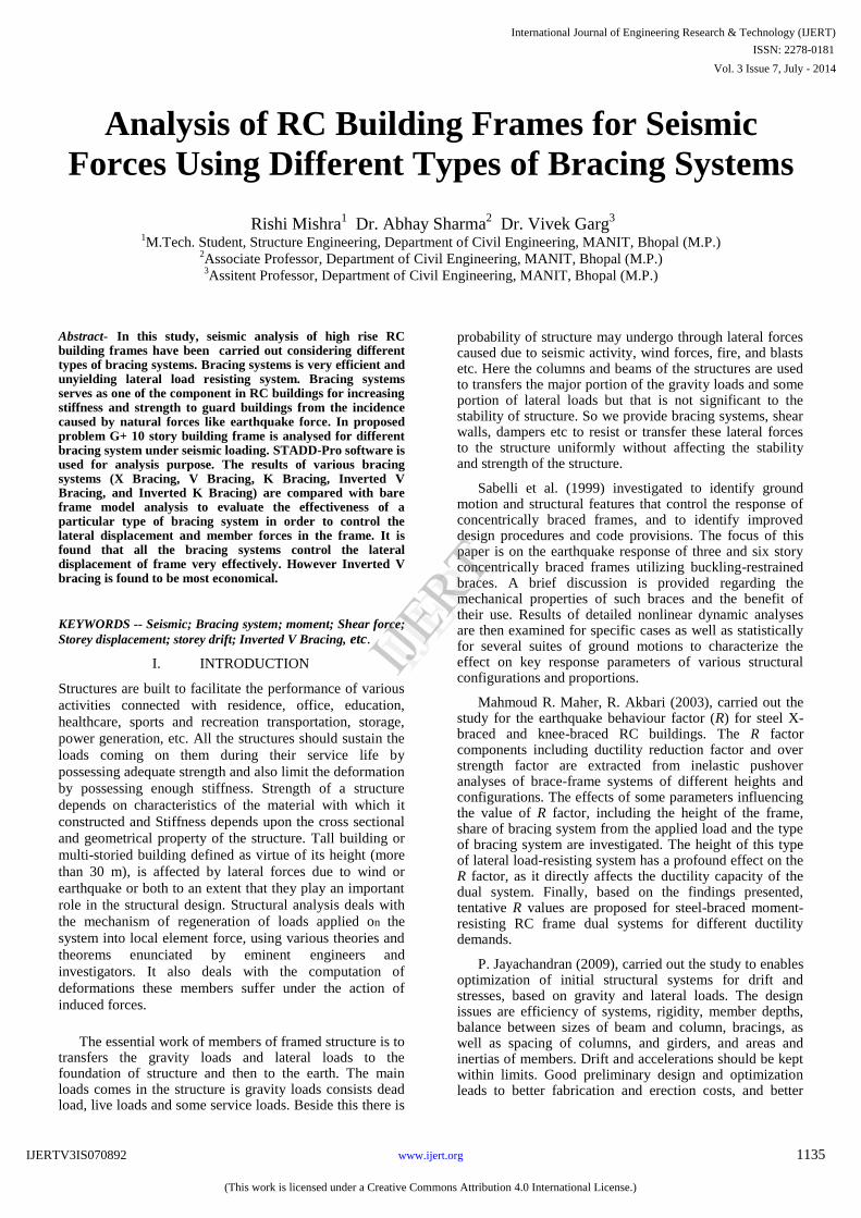
Fig 1: Elevation of proposed structural frame
Fig 2: Plan of proposed structural frame
Case 1: Structure frame without Bracing system
Case 2: Structure with X Bracing system
International Journal of Engineering Research & Technology (IJERT)
IJERT
IJERT
ISSN: 2278-0181
www.ijert.org
Vol. 3 Issue 7, July - 2014
IJERTV3IS070892
(This work is licensed under a Creative Commons Attribution 4.0 International License.)
1136
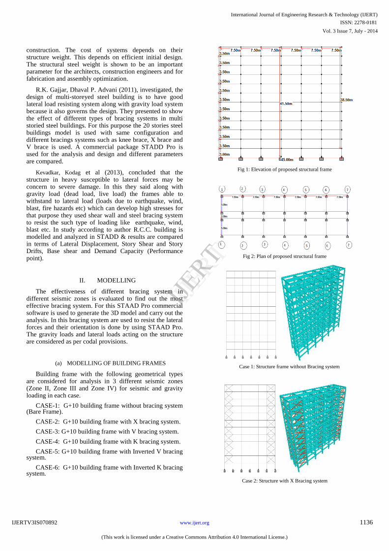
Case 3: Structure with V Bracing system
Case 4: Structure with K Bracing system
Case 5: Structure with Inverted V Bracing system
Case 6: Structure with Inverted K Bracing system
Fig 3: Proposed structure with different type of bracing systems
(b) MATERIAL AND GEOMETRICAL PROPERTIES
Following material properties are considered for the modelling of the proposed structure frame:-
Table 1: Details of Material and geometrical property
S. No. Description Parameter
1 Depth of foundation 3.0 m
2 Floor to Floor height 3.50 m
3 Grade of concrete M-25
4 Type of steel Fe-415
5 Column size (Bottom 2 storey) 0.6 m x0.6 m
6 Column size (top 8 storey) 0.5 m x0.5 m
7 Beam size in x-dir 0.3 m x 0.6 m
8 Beam size in z-dir 0.3 m x 0.5 m
9 Unit wt. of masonry wall 20 kN/m3
10 Slab thickness 150 mm
(c) LOADING CONDITIONS
Following loadings are adopted for analysis:-
1) Dead Loads: a. Self weight of Slab = 3.75 kN/m
2
b. Floor Finish load = 1 kN/m2
c. Wall Load in X direction= 11.6 kN/m
d. Wall Load in Z direction= 12 kN/m
2) Live Loads:
a. Live Load on typical floors = 4 kN/m2
3) Earth Quake Loads: The earth quake loads are derived for following seismic parameters as per IS: 1893(2002)
a. Earth Quake Zone-II,III,IV
b. Response Reduction Factor: 5
c. Importance Factor: 1
d. Damping: 5%
e. Soil Type: Hard Soil
III. RESULT & DISCUSSION
Find the results for axial force, shear force, bending, displacement, story drift etc & then compare the results to distinguish the effective system between provided different bracing systems in different seismic zones. Following tables and graphs are presented to find optimum system to resist seismic forces under following heads :-
a. MAXIMUM LATERAL DISPLACEMENT
The comparative study of lateral displacements in structures having different bracing systems is shown in table 2 & 3 and in Fig 4 & 5. It is found that the minimum displacement in structures are seen in X bracing and in Inverted V bracing for all seismic zones.
International Journal of Engineering Research & Technology (IJERT)
IJERT
IJERT
ISSN: 2278-0181
www.ijert.org
Vol. 3 Issue 7, July - 2014
IJERTV3IS070892
(This work is licensed under a Creative Commons Attribution 4.0 International License.)
1137
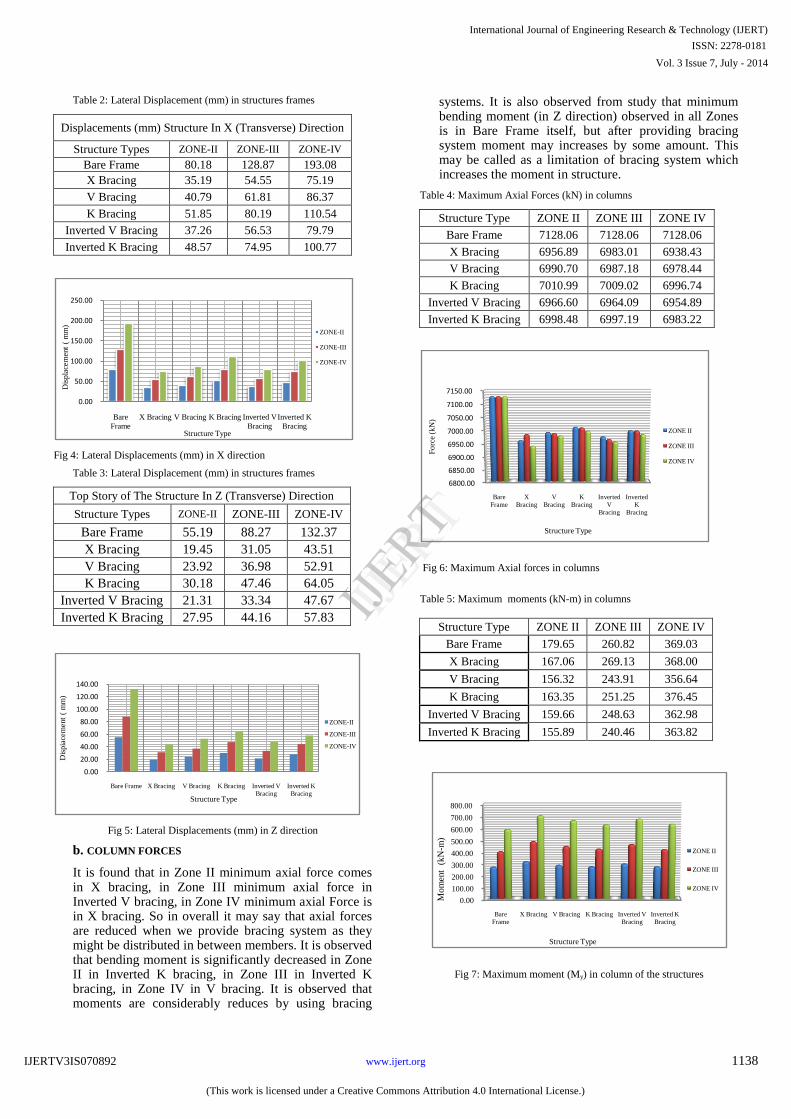
Table 2: Lateral Displacement (mm) in structures frames
Displacements (mm) Structure In X (Transverse) Direction
Structure Types ZONE-II ZONE-III ZONE-IV
Bare Frame 80.18 128.87 193.08
X Bracing 35.19 54.55 75.19
V Bracing 40.79 61.81 86.37
K Bracing 51.85 80.19 110.54
Inverted V Bracing 37.26 56.53 79.79
Inverted K Bracing 48.57 74.95 100.77
Fig 4: Lateral Displacements (mm) in X direction
Table 3: Lateral Displacement (mm) in structures frames
Top Story of The Structure In Z (Transverse) Direction
Structure Types ZONE-II ZONE-III ZONE-IV
Bare Frame 55.19 88.27 132.37
X Bracing 19.45 31.05 43.51
V Bracing 23.92 36.98 52.91
K Bracing 30.18 47.46 64.05
Inverted V Bracing 21.31 33.34 47.67
Inverted K Bracing 27.95 44.16 57.83
Fig 5: Lateral Displacements (mm) in Z direction
b. COLUMN FORCES
It is found that in Zone II minimum axial force comes in X bracing, in Zone III minimum axial force in Inverted V bracing, in Zone IV minimum axial Force is in X bracing. So in overall it may say that axial forces are reduced when we provide bracing system as they might be distributed in between members. It is observed that bending moment is significantly decreased in Zone II in Inverted K bracing, in Zone III in Inverted K bracing, in Zone IV in V bracing. It is observed that moments are considerably reduces by using bracing
systems. It is also observed from study that minimum bending moment (in Z direction) observed in all Zones is in Bare Frame itself, but after providing bracing system moment may increases by some amount. This may be called as a limitation of bracing system which increases the moment in structure.
Table 4: Maximum Axial Forces (kN) in columns
Structure Type ZONE II ZONE III ZONE IV
Bare Frame 7128.06 7128.06 7128.06
X Bracing 6956.89 6983.01 6938.43
V Bracing 6990.70 6987.18 6978.44
K Bracing 7010.99 7009.02 6996.74
Inverted V Bracing 6966.60 6964.09 6954.89
Inverted K Bracing 6998.48 6997.19 6983.22
Fig 6: Maximum Axial forces in columns
Table 5: Maximum moments (kN-m) in columns
Structure Type ZONE II ZONE III ZONE IV
Bare Frame 179.65 260.82 369.03
X Bracing 167.06 269.13 368.00
V Bracing 156.32 243.91 356.64
K Bracing 163.35 251.25 376.45
Inverted V Bracing 159.66 248.63 362.98
Inverted K Bracing 155.89 240.46 363.82
Fig 7: Maximum moment (My) in column of the structures
0.00
50.00
100.00
150.00
200.00
250.00
Bare
Frame
X Bracing V Bracing K Bracing Inverted V
Bracing
Inverted K
Bracing
Dis
pla
cem
ent
( m
m)
Structure Type
ZONE-II
ZONE-III
ZONE-IV
0.00
20.00
40.00
60.00
80.00
100.00
120.00
140.00
Bare Frame X Bracing V Bracing K Bracing Inverted V
Bracing
Inverted K
Bracing
Dis
pia
cem
ent
( m
m)
Structure Type
ZONE-II
ZONE-III
ZONE-IV
6800.00
6850.00
6900.00
6950.00
7000.00
7050.00
7100.00
7150.00
Bare
Frame
X
Bracing
V
Bracing
K
Bracing
Inverted
V
Bracing
Inverted
K
Bracing
Fo
rce
(kN
)
Structure Type
ZONE II
ZONE III
ZONE IV
0.00
100.00
200.00
300.00
400.00
500.00
600.00
700.00
800.00
Bare
Frame
X Bracing V Bracing K Bracing Inverted V
Bracing
Inverted K
Bracing
Mom
ent
(kN
-m)
Structure Type
ZONE II
ZONE III
ZONE IV
International Journal of Engineering Research & Technology (IJERT)
IJERT
IJERT
ISSN: 2278-0181
www.ijert.org
Vol. 3 Issue 7, July - 2014
IJERTV3IS070892
(This work is licensed under a Creative Commons Attribution 4.0 International License.)
1138
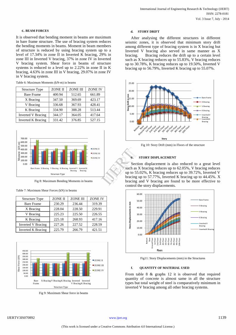
c. BEAM FORCES
It is observed that bending moment in beams are maximum in bare frame structure. The use of bracing system reduces the bending moments in beams. Moment in beam members of structure is reduced by using bracing system up to a level of 17.34% in zone II in Inverted K bracing, 29% in zone III in Inverted V bracing, 37% in zone IV in Inverted V bracing system. Shear force in beams of structure systems is reduced to a level up to 2.22% in zone II in K bracing, 4.63% in zone III in V bracing, 29.07% in zone IV in V bracing system.
Table 6: Maximum Moments (kN-m) in beams
Structure Type ZONE II ZONE III ZONE IV
Bare Frame 400.94 512.65 661.89
X Bracing 347.50 369.69 423.17
V Bracing 336.68 367.93 428.41
K Bracing 334.90 388.28 513.44
Inverted V Bracing 344.17 364.05 417.64
Inverted K Bracing 331.42 376.85 527.15
Fig 8: Maximum Bending Moments in beams
Table 7: Maximum Shear Forces (kN) in beams
Structure Type ZONE II ZONE III ZONE IV
Bare Frame 230.29 236.44 319.39
X Bracing 228.04 228.50 229.91
V Bracing 225.23 225.50 226.55
K Bracing 225.18 268.93 417.16
Inverted V Bracing 227.26 227.52 228.59
Inverted K Bracing 225.79 266.79 421.51
Fig 9: Maximum Shear force in beams
d.
STORY DRIFT
After analysing the different structures in different
seismic zones, it is observed that minimum story drift
among different type of bracing system is in X bracing but
Inverted V bracing also served in same manner as X
bracing. Bracing reduces the drift up to a certain level such as X bracing reduces up to 55.83%, V bracing reduces up to 30.78%, K bracing reduces up to 19.50%, Inverted V bracing up to 56.79%, Inverted K bracing up to 55.07%.
Fig 10:
Story
Drift
(mm)
in
Floors
of
the
structure
e. STORY
DISPLACEMENT
Section displacement is also reduced to a great level such as X bracing reduces up to 62.05%, V bracing reduces up to 55.02%, K bracing reduces up to 39.72%, Inverted V bracing up to 57.77%, Inverted K bracing up to 44.45%. X bracing and V bracing are found to be more effective to control the story displacements.
Fig11: Story Displacements (mm) in the Structures
f.
QUANTITY OF MATERIAL USED
From table 8 & graphs 12 it is observed that required
quantity of concrete is almost same in all the structure
types but total weight of steel is comparatively minimum in
inverted V bracing among all other bracing systems.
0.00
100.00
200.00
300.00
400.00
500.00
600.00
700.00
Bare Frame X Bracing V Bracing K Bracing Inverted V
Bracing
Inverted K
Bracing
Mom
ent
(kN
- m)
Structure Type
ZONE II
ZONE III
ZONE IV
0.00
50.00
100.00
150.00
200.00
250.00
300.00
350.00
400.00
450.00
Bare
Frame
X Bracing V Bracing K Bracing Inverted
V Bracing
Inverted
K Bracing
Shea
r F
orc
e (k
N)
Structure Type
ZONE II
ZONE III
ZONE IV
0.00
5.00
10.00
15.00
20.00
25.00
Sto
ry D
rift
in m
m
Story
Bare Frame
X Bracing
V Bracing
K Bracing
Inverted V BracingInverted K Bracing
0.00
10.00
20.00
30.00
40.00
50.00
60.00
Bo
tto
m
Bas
e
Gro
un
d F
loo
r
1st
Flo
or
2n
d F
loo
r
3rd
Flo
or
4th
Flo
or
5th
Flo
or
6th
Flo
or
7th
Flo
or
8th
Flo
or
9th
Flo
or
10th
Flo
or
Sto
ry D
isp
lace
men
ts in
mm
Bare Frame
X Bracing
V Bracing
K Bracing
Inverted V Bracing
Inverted K Bracing
International Journal of Engineering Research & Technology (IJERT)
IJERT
IJERT
ISSN: 2278-0181
www.ijert.org
Vol. 3 Issue 7, July - 2014
IJERTV3IS070892
(This work is licensed under a Creative Commons Attribution 4.0 International License.)
1139
Table 8: Quantity of materials used in structure
Structure Type Concre
te (m3)
Steel
Reinforceme
nt (kN)
Bracin
g
Weigh
t (kN)
Total
Steel
used(k
N)
Bare Frame 806.80 1208.29 0.00 1208.29
X Bracing 829.60 817.56 1161.4
2 1978.98
V Bracing 836.50 844.47 523.61 1368.08
K Bracing 838.30 927.81 720.62 1648.43
Inverted V
Bracing 834.00 799.28 472.05 1271.32
Inverted K
Bracing 838.30 907.73 782.18 1689.91
Fig 8: Comparison of Quantity of material used in structure
CONCLUSIONS
Following are the salient conclusions of the study:- 1. The concept of using steel bracing is advantageous to
resist the seismic forces. 2. The bracing system effectively reduces the lateral
displacement (up to 80%) of the structure compared to Bare frame.
3. Steel bracings the amount of forces in members significantly reduces.
4. Bracing system proves as a effective member to control the story drift (up to 56%) in structures as compare to Bare frames.
5. After using bracing member as a resistive member margin of safety against collapse increased.
REFERENCES
1)
Ravi
kumar
G.
and
Kalyanaraman,-“Earthquake design and retrofit
of RC multi-storied buildings with steel bracing”, National Program on Earthquake Engineering Education, 2005.
2)
Wilkinson S.M., Hiley R.A., -
“A non-linear response history model
for the earthquake analysis of high-rise
framed buildings”,
Computers
&Frames, Volume 84,
Issues 5–6, January 2006
3)
Ferraioli, M. Avossa, -“Performance based assessment of R.C.
buildings strengthened with steel braces”, Proceedings of the 2nd International Congress Naples, Italy, 2006.
4)
Ghaffar
zadeh H. and Maheri M.R.,-“Cyclic tests on the internally
braced RC frames”, Dept. of Civil Engineering, Shiraz University, Shiraz, Iran, 2006.
5)
M.A. Youssefa, _H. Ghaffarzadehb, M. Nehdia,-“Earthquake
performance of RC frames with concentric internal steel bracing” -Engineering Frames 29, 2007.
6)
Jun Ji, Amr S. Elnashai, Daniel A. Kuchma,-
' An analytical
framework for earthquake fragility analysis of RC high-rise buildings ' Engineering
Frames, Volume 29, Issue 12, Pages 3197–
3209, December 2007.
7)
Mahmood
Hosseini, Peyman
Shadman
Heidari and Mojtaba
Heravi,-“Analytical and Experimental Study of the Effect of Bracing Pattern
In The Lateral Load Bearing Capacity Of Concentrically Braced
Steel Frames”, -The 14th
World Conference on Earthquake Engineering October 12-17, 2008, Beijing, China.
8)
M.R. Maheri and H. Ghaffarzadeh, -“Earthquake design basis for
internally braced frame”, The 14 Th World Conference on Earthquake Engineering October 12-17, 2008, Beijing, China.
9)
Abhishek R, BijuV, -“Effect of Lateral load pattern in Pushover
analysis”, 10th National Conference on Technological Trends (NCTT09) 6-7 Nov 2008.
10)
L. Di Sarnoa, A.S. Elnashaib, -
“Bracing systems for earthquake
retrofitting of steel frames”,-Journal of Constructional Steel Research 65 (2009) 452–465, 15 February 2009.
11)
Wang, G.,Wang, W., Katayoun B., -
„Earthquake
instrumentation of
high-rise
buildings,
Progress
in
Natural
Science,
Volume 19, Issue 2, Pages 223–227, 10 February 2009.
12)
IS 1893 : 2002, “Indian Standard criteria for earthquake resistant design of frames”, Part 1 General provisions and buildings, Draft of
Fifth Revision, Bureau of Indian Standards, New Delhi, 2002.
13)
IS 13920: 1987, “Ductile detailing of reinforced Concrete structures
subjected to Seismic forces -code of practice”, Third reprint
November,
Bureau of Indian Standards, New Delhi, November
1993.
14)
IS 800:2007, “General construction in steel –
Code of practice
Bureau of Indian standards, New Delhi”.
15)
Thandavamoorthy T.S., (2011), “Structural Analysis”, Oxford University Press , New Delhi, India
16)
Shrikhande Manish and Agrawal Pankaj “Earthquake Resistant
Design of Structures.” PHI Learning Private Limited New Delhi (2010).
17)
Duggal S.K “Earthquake Resistant Design of Structures.” Oxford
University Press YMCA Library Building, Jai Singh Road, New Delhi (2010).
0.00
500.00
1000.00
1500.00
2000.00
2500.00
Bare Frame X Bracing V Bracing K Bracing Inverted V Bracing
Inverted K Bracing
Qu
an
tity
of
Ma
teri
als
Structure Type
Concrete (m3)
Total Steel used (kN)
International Journal of Engineering Research & Technology (IJERT)
IJERT
IJERT
ISSN: 2278-0181
www.ijert.org
Vol. 3 Issue 7, July - 2014
IJERTV3IS070892
(This work is licensed under a Creative Commons Attribution 4.0 International License.)
1140

![Closing the gap Between Design and reality of building ... · amounted to 69 percent of the total load in a case study of a six-storeyed office building [10]. Revising plug loads](https://img.dokumen.tips/doc/110x75/5ebfec4697389926ad05ea1b/closing-the-gap-between-design-and-reality-of-building-amounted-to-69-percent.jpg)