Embed Size (px)
Citation preview

International Journal of Recent Technology and Engineering (IJRTE)
ISSN: 2277-3878, Volume-8, Issue-1, May 2019
1317
Published By:
Blue Eyes Intelligence Engineering
& Sciences Publication Retrieval Number A3127058119/19©BEIESP
Abstract: Multistoreyed buildings are used for both residential
and commercial purposes, for commercial usage flat slab
systems are adopted over traditional frame structures. This is
due to reduced floor to floor height, use of space, easier
formwork and shorter construction time. In the present work to
improve the performance of the building, A G+12 storey flat slab
building with drop and without drop are proposed for the
seismic analysis. To resist the lateral loading due to earthquake,
different types of shear wall such as concrete and perforated
coupled shear walls are used in the structure. Both linear
dynamic and non-linear dynamic analysis will be done using the
software ETABS and the results will be compared
Keywords: Flat Slab, Shear Wall, Punching Shear, Storey Drift.
I. INTRODUCTION
Multistoreyed flat slab buildings are generally used for
commercial purposes. In a flat slab building the slab are
supported by columns without the use of internal beams. The
loads are directly transferred from slab to the column. The
advantages of applying flat slabs are mainly like depth
solution, flat soffit and flexibility in design layout. There are
different types of flat slab mainly flat slab without drop, flat
slab with drop, flat slab with column head, flat slab with
column head and drop. When drop panels are provided it
increases the negative moment capacity and shear strength of
slabs. Flat slab has got lower stiffness when compared to
beam column frame structures which results in larger
deflections.
Punching failure is the most critical problem when
determining the thickness of flat slab. In order to resist lateral
loads and to increase stiffness, shear walls are usually
provided. Shear walls are the vertical structural member
which resist the combination of shear, moment and axial
load. These walls are built throughout the height of the
building with a thickness of 150 mm to 400 mm. The shape
and size of shear wall depend upon the geometry and height
of building.
Non-linear dynamic analysis can be considered as the most
accurate method in finding the response of building under
seismic loading. Linear dynamic response-spectrum analysis
is also useful for better selection of flat slab models.
Revised Manuscript Received on May 22, 2019.
Mathew Paul, School of mechanical and science, VIT Chennai, Tamil
Nadu .India
K Vasugi, Assistant Professor (Sr), School of Mechanical and Building
Science, VIT, Chennai, Tamil Nadu India
Noel Francis, School of mechanical and science, VIT Chennai, Tamil
Nadu India
II. LITERATURE REVIEW
T. M Roberts [1] studied seismic resistance of steel plate
shear walls. Shear walls are used to resist lateral loads due to
earthquake. 5 continuous H shaped steel shear walls were
used. The stiffness decreases with increase size of opening in
shear wall.
Fayazuddin et al., [2] studied analysis of flat slab
multistoreyed building with and without shear walls under
wind loads. The introduction of shear wall resulted in
reduction of column moments. The building can be
strengthened against lateral loads by providing shear wall.
Rajib et al., [3] compared the performance of 15 storey flat
slab building with and without shear wall. Storey drift, storey
displacement and storey shear results were compared. Flat
slab alone is weak in resisting lateral loads, hence addition of
shear wall is necessary.
Kavin and Dipali [4] done a comparative study on steel
building with different steel patterns. X type of frame has got
less displacement when compared to all other patterns.
Ashwini and Dr. Shivakumara [5] performed pushover
analysis for a 10 storeyed flat slab building with and without
shear wall. The addition of perimeter beam has got no effect
in reducing the displacement of the building.
III. PROBLEM DEFINITION
Flat slab building without drop and with drop are weak in
resisting lateral loads. The drift values were also exceeding
the limit. Usually the flat slab buildings are weak in resisting
lateral loads, hence addition of shear walls in resisting the
lateral forces will also be studied. The types of shear wall that
will be used in this study will be concrete shear wall and
perforated coupled shear wall.
IV. OBJECTIVES
1. Flat slab buildings subjected to seismic analysis.
2. Influence of different shear walls on the building.
3. Linear (RESPONSE SPECTRUM ANALYSIS) and
non-linear dynamic(TIME HISTORY) analysis on the
building.
4. Storey drift, storey displacement, storey shear and
punching shear results.
Behavior of Multi- Storeyed Building for Flat
Slab System with and Without Shear Wall
under Seismic Loading Mathew Paul, K. Vasugi, Noel Francis

Behavior of Multi- Storeyed Building for Flat Slab System with and Without Shear Wall under Seismic Loading
1318
Published By:
Blue Eyes Intelligence Engineering
& Sciences Publication Retrieval Number A3127058119/19©BEIESP
V. MODELLING AND ANALYSIS
A G+12 storey building is taken for seismic analysis. The flat
slab building consists of 9 bays in both X and Y direction
with a bay width of 8m in X and Y direction. Both linear and
non-linear dynamic analysis will be done. The six flat slab
buildings are
1. Model 1 – Flat slab without drop
2. Model 2 – Flat slab with drop
3. Model 3 – Flat slab without drop with concrete shear wall
4. Model 4 – Flat slab without drop with perforated coupled
shear wall
5. Model 5 - Flat slab with drop with concrete shear wall
6. Model 6 – Flat slab with drop with perforated coupled
shear wall. Specifications of flat slab without drop
Type of building Commercial
No. of storey G+12
Height of storey 3 m
Grade of concrete M30
Grade of steel HYSD 415
Live load 3 kN/m2
Floor finish 1 kN/m2
Wall load 1.25 kN/m2
Size of perimeter beam 500 X 750 mm
Size of column 800 X 800 mm
Thickness of slab 250 mm
Specification of flat slab with drop
Type of building Commercial
No. of storey G+12
Height of storey 3 m
Grade of concrete M30
Grade of steel HYSD 415
Live load 3 kN/m2
Floor finish 1 kN/m2
Wall load 1.25 kN/m2
Size of perimeter beam 450 X 700 mm
Size of column 750 X 750 mm
Thickness of slab 250 mm
Thickness of drop 350 mm
Size of interior drop 3000 X 3000 mm
Size of exterior drop 1875 X 3000 mm
Size of corner drop 1875 X 1875 mm
These are the basic specification of both buildings. In to these
buildings two types of shear walls are also added.
• Concrete shear wall.
• Perforated coupled shear wall.
Fig 1: Typical floor plan for G+12 storey flat slab
building without drop
Fig 2 : 3D model for G+12 storey flat slat building
without drop
Fig 3 : Typical floor plan for G+12 storey flat slab
building with drop
Fig 4 : 3D model for flat slab building with drop
International Journal of Recent Technology and Engineering (IJRTE)
ISSN: 2277-3878, Volume-8, Issue-1, May 2019
1319
Published By:
Blue Eyes Intelligence Engineering
& Sciences Publication Retrieval Number A3127058119/19©BEIESP
Fig 3 : 3D model for flat slab without drop with 250
mm concrete shear wall
Fig 4 : 3D model for flat slab without drop with 250
mm perforated coupled shear wall
Fig 5: 3D model for flat slab with drop with 200 mm
concrete shear wall
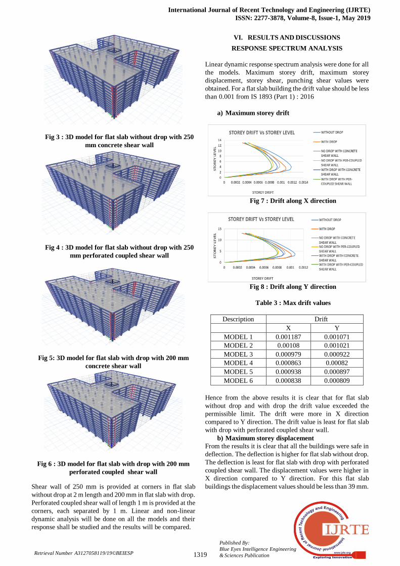
Fig 6 : 3D model for flat slab with drop with 200 mm
perforated coupled shear wall
Shear wall of 250 mm is provided at corners in flat slab
without drop at 2 m length and 200 mm in flat slab with drop.
Perforated coupled shear wall of length 1 m is provided at the
corners, each separated by 1 m. Linear and non-linear
dynamic analysis will be done on all the models and their
response shall be studied and the results will be compared.
VI. RESULTS AND DISCUSSIONS
RESPONSE SPECTRUM ANALYSIS
Linear dynamic response spectrum analysis were done for all
the models. Maximum storey drift, maximum storey
displacement, storey shear, punching shear values were
obtained. For a flat slab building the drift value should be less
than 0.001 from IS 1893 (Part 1) : 2016
a) Maximum storey drift
Fig 7 : Drift along X direction
Fig 8 : Drift along Y direction
Table 3 : Max drift values
Description Drift
X Y
MODEL 1 0.001187 0.001071
MODEL 2 0.00108 0.001021
MODEL 3 0.000979 0.000922
MODEL 4 0.000863 0.00082
MODEL 5 0.000938 0.000897
MODEL 6 0.000838 0.000809
Hence from the above results it is clear that for flat slab
without drop and with drop the drift value exceeded the
permissible limit. The drift were more in X direction
compared to Y direction. The drift value is least for flat slab
with drop with perforated coupled shear wall.
b) Maximum storey displacement
From the results it is clear that all the buildings were safe in
deflection. The deflection is higher for flat slab without drop.
The deflection is least for flat slab with drop with perforated
coupled shear wall. The displacement values were higher in
X direction compared to Y direction. For this flat slab
buildings the displacement values should be less than 39 mm.

Behavior of Multi- Storeyed Building for Flat Slab System with and Without Shear Wall under Seismic Loading
1320
Published By:
Blue Eyes Intelligence Engineering
& Sciences Publication Retrieval Number A3127058119/19©BEIESP
Fig 9 : Displacement along X direction
Fig 10 : Displacement along Y direction
Table 4 : Maximum displacement values
Description Displacement (mm)
X Y
MODEL 1 31.37 28.00
MODEL 2 28.32 26.21
MODEL 3 27.08 24.98
MODEL 4 24.95 23.98
MODEL 5 25.31 23.92
MODEL 6 23.72 23.60
c) Storey shear
The storey shear is maximum for flat slab with drop with
perforated coupled shear wall in X direction and flat slab
without drop with perforated coupled shear wall in Y
direction.
Table 5 : Storey shear values
Description Storey shear (kN)
X Y
MODEL 1 9503 10755
MODEL 2 10185 11040
MODEL 3 10998 12210
MODEL 4 12142 13197
MODEL 5 11444 12268
MODEL 6 12329 13066
d) Punching shear
Punching shear is obtained by demand by capacity ratio. For
a flat slab building to be safe under punching the demand by
capacity ratio should be less than 1. Punching shear obtained
for all the buildings were less than 1, hence safe.
Time History Analysis
EL-CENTRO time histroy datas were used for non-linear
dynamic analysis. In time histroy analysis the actual recorded
earthquake force is directly applied to the mathematical
model.
a) Maximum storey drift
Fig 11 : Drift along X direction
Fig 12 : Drift along Y direction
Table 6 : Maximum storey drift
Description Drift
X Y
MODEL 1 0.001281 0.001128
MODEL 2 0.001151 0.001071
MODEL 3 0.001095 0.00097
MODEL 4 0.000921 0.000874
MODEL 5 0.000988 0.000939
MODEL 6 0.000894 0.000862
For flat slab building the drift value should be less than
0.001. When non-linear dynamic analysis was done, the drift
values exceeded for flat slab without drop and flat slab with
drop in both X and Y direction and flat slab without drop
with concrete shear wall in X direction. The drift values were
least for flat slab with drop with perforated coupled shear
wall.
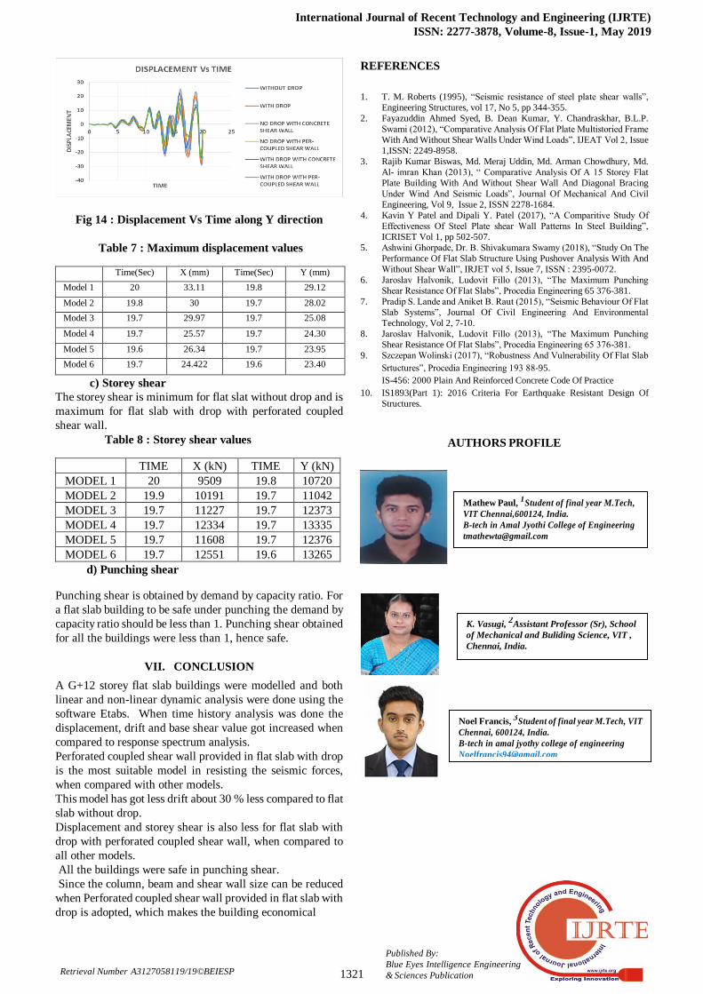
b) Maximum storey displacement
The displacement values were taken with respect to time.The
displacement was maximum for flat slat without drop in both
X and Y direction. The displacement were least for flat slab
with drop with perforated coupled shear wall. For this flat
slab buildings the displacement should be less than 39 mm.
Fig 13 : Displacement Vs Time along X direction
International Journal of Recent Technology and Engineering (IJRTE)
ISSN: 2277-3878, Volume-8, Issue-1, May 2019
1321
Published By:
Blue Eyes Intelligence Engineering
& Sciences Publication Retrieval Number A3127058119/19©BEIESP
Fig 14 : Displacement Vs Time along Y direction
Table 7 : Maximum displacement values
Time(Sec) X (mm) Time(Sec) Y (mm)
Model 1 20 33.11 19.8 29.12
Model 2 19.8 30 19.7 28.02
Model 3 19.7 29.97 19.7 25.08
Model 4 19.7 25.57 19.7 24.30
Model 5 19.6 26.34 19.7 23.95
Model 6 19.7 24.422 19.6 23.40
c) Storey shear
The storey shear is minimum for flat slat without drop and is
maximum for flat slab with drop with perforated coupled
shear wall.
Table 8 : Storey shear values
TIME X (kN) TIME Y (kN)
MODEL 1 20 9509 19.8 10720
MODEL 2 19.9 10191 19.7 11042
MODEL 3 19.7 11227 19.7 12373
MODEL 4 19.7 12334 19.7 13335
MODEL 5 19.7 11608 19.7 12376
MODEL 6 19.7 12551 19.6 13265
d) Punching shear
Punching shear is obtained by demand by capacity ratio. For
a flat slab building to be safe under punching the demand by
capacity ratio should be less than 1. Punching shear obtained
for all the buildings were less than 1, hence safe.
VII. CONCLUSION
A G+12 storey flat slab buildings were modelled and both
linear and non-linear dynamic analysis were done using the
software Etabs. When time history analysis was done the
displacement, drift and base shear value got increased when
compared to response spectrum analysis.
Perforated coupled shear wall provided in flat slab with drop
is the most suitable model in resisting the seismic forces,
when compared with other models.
This model has got less drift about 30 % less compared to flat
slab without drop.
Displacement and storey shear is also less for flat slab with
drop with perforated coupled shear wall, when compared to
all other models.
All the buildings were safe in punching shear.
Since the column, beam and shear wall size can be reduced
when Perforated coupled shear wall provided in flat slab with
drop is adopted, which makes the building economical
REFERENCES
1. T. M. Roberts (1995), “Seismic resistance of steel plate shear walls”,
Engineering Structures, vol 17, No 5, pp 344-355.
2. Fayazuddin Ahmed Syed, B. Dean Kumar, Y. Chandraskhar, B.L.P.
Swami (2012), “Comparative Analysis Of Flat Plate Multistoried Frame
With And Without Shear Walls Under Wind Loads”, IJEAT Vol 2, Issue
1,ISSN: 2249-8958.
3. Rajib Kumar Biswas, Md. Meraj Uddin, Md. Arman Chowdhury, Md.
Al- imran Khan (2013), “ Comparative Analysis Of A 15 Storey Flat
Plate Building With And Without Shear Wall And Diagonal Bracing
Under Wind And Seismic Loads”, Journal Of Mechanical And Civil
Engineering, Vol 9, Issue 2, ISSN 2278-1684.
4. Kavin Y Patel and Dipali Y. Patel (2017), “A Comparitive Study Of
Effectiveness Of Steel Plate shear Wall Patterns In Steel Building”,
ICRISET Vol 1, pp 502-507.
5. Ashwini Ghorpade, Dr. B. Shivakumara Swamy (2018), “Study On The
Performance Of Flat Slab Structure Using Pushover Analysis With And
Without Shear Wall”, IRJET vol 5, Issue 7, ISSN : 2395-0072.
6. Jaroslav Halvonik, Ludovit Fillo (2013), “The Maximum Punching
Shear Resistance Of Flat Slabs”, Procedia Engineering 65 376-381.
7. Pradip S. Lande and Aniket B. Raut (2015), “Seismic Behaviour Of Flat
Slab Systems”, Journal Of Civil Engineering And Environmental
Technology, Vol 2, 7-10.
8. Jaroslav Halvonik, Ludovit Fillo (2013), “The Maximum Punching
Shear Resistance Of Flat Slabs”, Procedia Engineering 65 376-381.
9. Szczepan Wolinski (2017), “Robustness And Vulnerability Of Flat Slab
Srtuctures”, Procedia Engineering 193 88-95.
IS-456: 2000 Plain And Reinforced Concrete Code Of Practice 10. IS1893(Part 1): 2016 Criteria For Earthquake Resistant Design Of
Structures.
AUTHORS PROFILE
Mathew Paul, 1
Student of final year M.Tech,
VIT Chennai,600124, India.
B-tech in Amal Jyothi College of Engineering
K. Vasugi, 2Assistant Professor (Sr), School
of Mechanical and Buliding Science, VIT ,
Chennai, India.
Noel Francis, 3
Student of final year M.Tech, VIT
Chennai, 600124, India.
B-tech in amal jyothy college of engineering
8606836676