Embed Size (px)
Citation preview

Analysis of Enclosures and Anti Vibration Devices for Electronic Equipment for Space Applications
G.S. Aglietti, and C. Schwingshackl
School of Engineering Sciences, Aeronautics and Astronautics, University of Southampton, UK
Abstract Electronic units form a considerable part of the spacecraft bus mass budget, and a significant mass saving could be made by improving their mechanical design. Attention is focussed on the analysis of typical enclosures for electronics, and the anti vibration devices for the Printed Circuit Boards (PCBs) currently used within the enclosures.
A crucial step to improve the equipment design is the accurate prediction of the vibration response of the electronics (i.e. populated PCBs), to the vibration environment experienced during launch. FE models of PCBs and Anti-Vibration Frames are presented and compared with the results obtained during random vibration tests
Introduction The expansion of the satellite market to cover applications ranging from Telecommunications to Space Science and Earth Observation has produced a steady increase in the production of electronic equipment for space applications [1]. This trend is likely to continue as crucial sectors in modern society have come to rely on satellite technologies; telecommunications being the most obvious example. For a typical satellite for telecoms - although the situation is very similar for other applications - electronic units form a considerable part of the spacecraft bus mass budget and, in general, between a quarter and a third of the total mass of equipment units is made up of their enclosure. This is generally made of aluminium alloy, and a significant mass saving could be made by improving the mechanical design. This situation is well known and in the year 2000, the European Space Agency, issued an Invitation To Tender on the subject (ITT Number 00.129.23 – Advanced Equipment Design). In this specific case it was stated that a significant mass saving could be achieved by replacing the Aluminium Alloy with composites i.e. Carbon Fibre Reinforced Plastics (CFRP). This approach has already been very successful with other structural components, e.g. conventional Aluminium honeycomb panel can be replaced by CFRP panels with possible mass savings around 30 %. Another advantage in the use of CFRP for the enclosures for electronic equipment is that when these are mounted on CFRP panels, the thermo elastic problems, which can be generated by large temperature fluctuations on the spacecraft, are avoided. A potential problem, in the use of CFRP for enclosures for electronics for space applications, is the reduced amount of radiation shielding offered by this material when compared to aluminium alloys. However the capability of CFRP to filter radiation can be strongly improved (to give performance superior to conventional Aluminium alloy) by intercalating the fibres (with the insertion of guest atoms /
molecules between the layers of the fibres) before fabricating the composite, as discussed in [2].
For electronic equipment, generally speaking, launch survival is the major mechanical design driver. This has been known for many years, and in the 1970’s NASA showed that 45% of the first-day spacecraft failures were due to damage caused by vibrations during launch [3]. At the time, several studies looked into the problem of the harsh vibration environment experienced by Printed Circuit Boards (PCB) during launch, and various solutions where proposed, e.g. [4], [5].
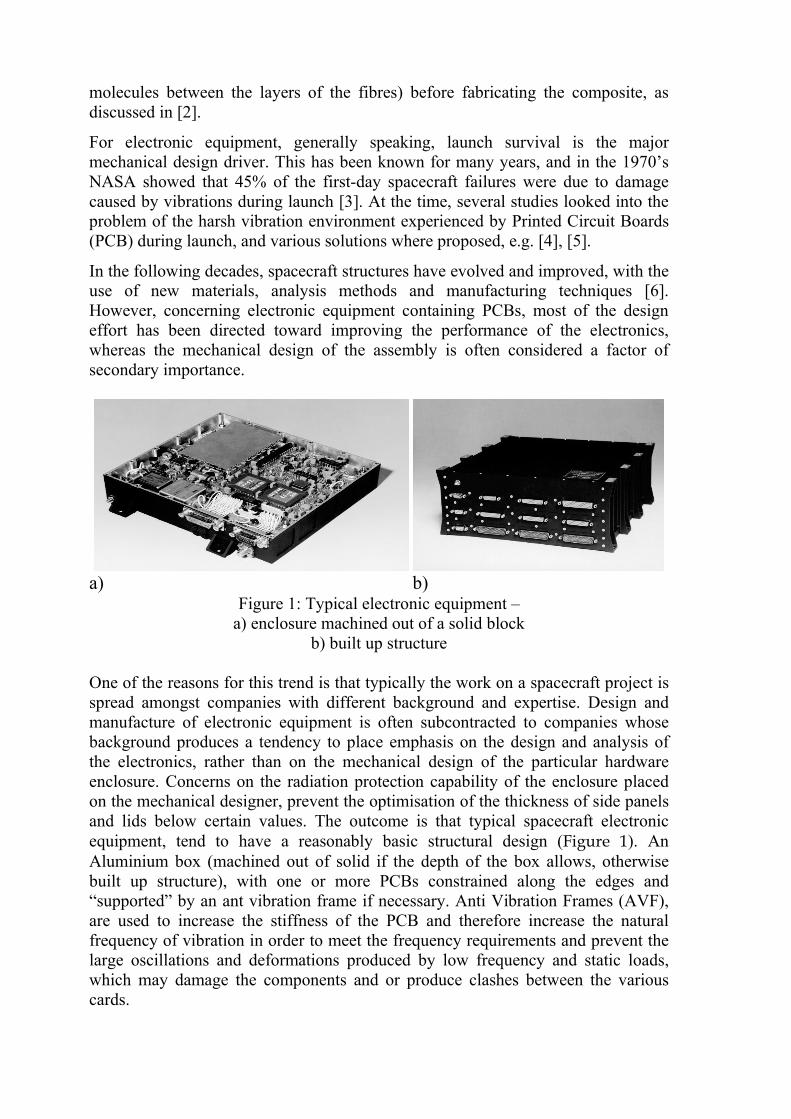
In the following decades, spacecraft structures have evolved and improved, with the use of new materials, analysis methods and manufacturing techniques [6]. However, concerning electronic equipment containing PCBs, most of the design effort has been directed toward improving the performance of the electronics, whereas the mechanical design of the assembly is often considered a factor of secondary importance.
a) b)
Figure 1: Typical electronic equipment – a) enclosure machined out of a solid block
b) built up structure
One of the reasons for this trend is that typically the work on a spacecraft project is spread amongst companies with different background and expertise. Design and manufacture of electronic equipment is often subcontracted to companies whose background produces a tendency to place emphasis on the design and analysis of the electronics, rather than on the mechanical design of the particular hardware enclosure. Concerns on the radiation protection capability of the enclosure placed on the mechanical designer, prevent the optimisation of the thickness of side panels and lids below certain values. The outcome is that typical spacecraft electronic equipment, tend to have a reasonably basic structural design (Figure 1). An Aluminium box (machined out of solid if the depth of the box allows, otherwise built up structure), with one or more PCBs constrained along the edges and “supported” by an ant vibration frame if necessary. Anti Vibration Frames (AVF), are used to increase the stiffness of the PCB and therefore increase the natural frequency of vibration in order to meet the frequency requirements and prevent the large oscillations and deformations produced by low frequency and static loads, which may damage the components and or produce clashes between the various cards.

Stiffening the PCBs can also be achieved by using other techniques, e.g. [7, 8, and 9] however AVF are by far the most commonly used devices. It must be remarked that AVF also provide a thermal path for the dissipation of the heat generated by the components, however this work focuses on their mechanical purpose, rather than their thermal function, which in principle can be carried out by other elements.
In the past, the structural dynamics of PCBs received some attention e.g. [10, 11, 12, 13 and 14] but in order to keep the pace with the progress in the electronics further work is necessary in the area of the mechanical design.
Mechanical requirements The mechanical requirements placed on equipment design are set by the authority in charge of the overall spacecraft development. These requirements aim to ensure that the equipment can withstand without failures the mechanical environment produced at the equipment location during launch. This environment consists of low frequency dynamics and steady accelerations, combined with random vibrations, acoustic loads and shocks.
Unfortunately, the exact determination of the dynamic loads that the equipment will experience on the spacecraft is not within the current state of the art. This is, in part, due to random characteristics of the phenomena which generate the vibrations (e.g. the fuel burning within the combustion chambers, turbulent aerodynamic boundary layer etc.), and in part due to the fact that the vibration level at the equipment-spacecraft interface depend strongly on the characteristics of the various equipment (i.e. mass distribution, geometry, stiffness). Besides that, the vibration environment on the spacecraft depends on the interaction of the spacecraft/launch vehicle, and cannot be established exactly until the dynamic characteristics of the spacecraft are defined. Relatively accurate values of the dynamic loads on the spacecraft can be obtained by using previous flight data for the same launcher and performing a coupled dynamic analysis using the Finite Element Method (FEM). However, the mathematical modelling of such a complex assembly composed of thousands of parts is a daunting task, and various approximations, introduced in order to keep the size of the model within reasonable limits, compromise the accuracy of the results. Without going into further details on the accuracy of the loads and their updates, whose responsibility ultimately rests with the launch authority and spacecraft main contractor, the current working practice is based on the use of a conservative set of mechanical requirements and specifications. All acoustic noise and vibrations are enveloped in a random vibration acceleration spectrum such as the one shown in Figure 5. The typical requirement is that the equipment must be able to endure - without failures - such spectra, applied at the mounting points of the equipment and for a certain period of time (usually 2 minutes).
Another important requirement concerns the lowest natural frequency of vibration allowed for the equipment, in order to avoid dynamic coupling with the low frequency modes of spacecraft and launch vehicle. For equipment weighting up to few kilograms this is usually 100 Hz.
Finally the equipment must be able to withstand the load factors which are produced during the launch phases. These loads are usually called Quasi Static Loads (QSL) since they are produced by relatively low frequency dynamics. An example of QSL specification for aerospace equipment could be 15 g applied simultaneously along the three axes. Compliance with this requirement is usually demonstrated with a high amplitude (e.g. 15 g) sine sweep test or detailed structural/stress analysis.
Thermal loads occurring during the active life of the electronic equipment once on orbit are also extremely important for the mechanical design. However this work focuses on the vibration environment during launch, and therefore thermal loads are not considered in this study.
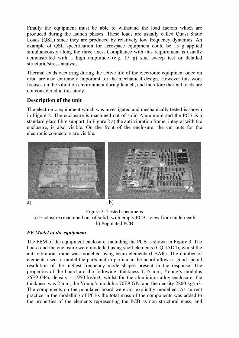
Description of the unit The electronic equipment which was investigated and mechanically tested is shown in Figure 2. The enclosure is machined out of solid Aluminium and the PCB is a standard glass fibre support. In Figure 2 a) the anti vibration frame, integral with the enclosure, is also visible. On the front of the enclosure, the cut outs for the electronic connectors are visible.
a) b)
Figure 2: Tested specimens a) Enclosure (machined out of solid) with empty PCB –view from underneath
b) Populated PCB FE Model of the equipment
The FEM of the equipment enclosure, including the PCB is shown in Figure 3. The board and the enclosure were modelled using shell elements (CQUAD4), whilst the anti vibration frame was modelled using beam elements (CBAR). The number of elements used to model the parts and in particular the board allows a good spatial resolution of the highest frequency mode shapes present in the response. The properties of the board are the following: thickness 1.55 mm, Young’s modulus 26E9 GPa, density = 1950 kg/m3, whilst for the aluminium alloy enclosure, the thickness was 2 mm, the Young’s modulus 70E9 GPa and the density 2800 kg/m3. The components on the populated board were not explicitly modelled. As current practice in the modelling of PCBs the total mass of the components was added to the properties of the elements representing the PCB as non structural mass, and
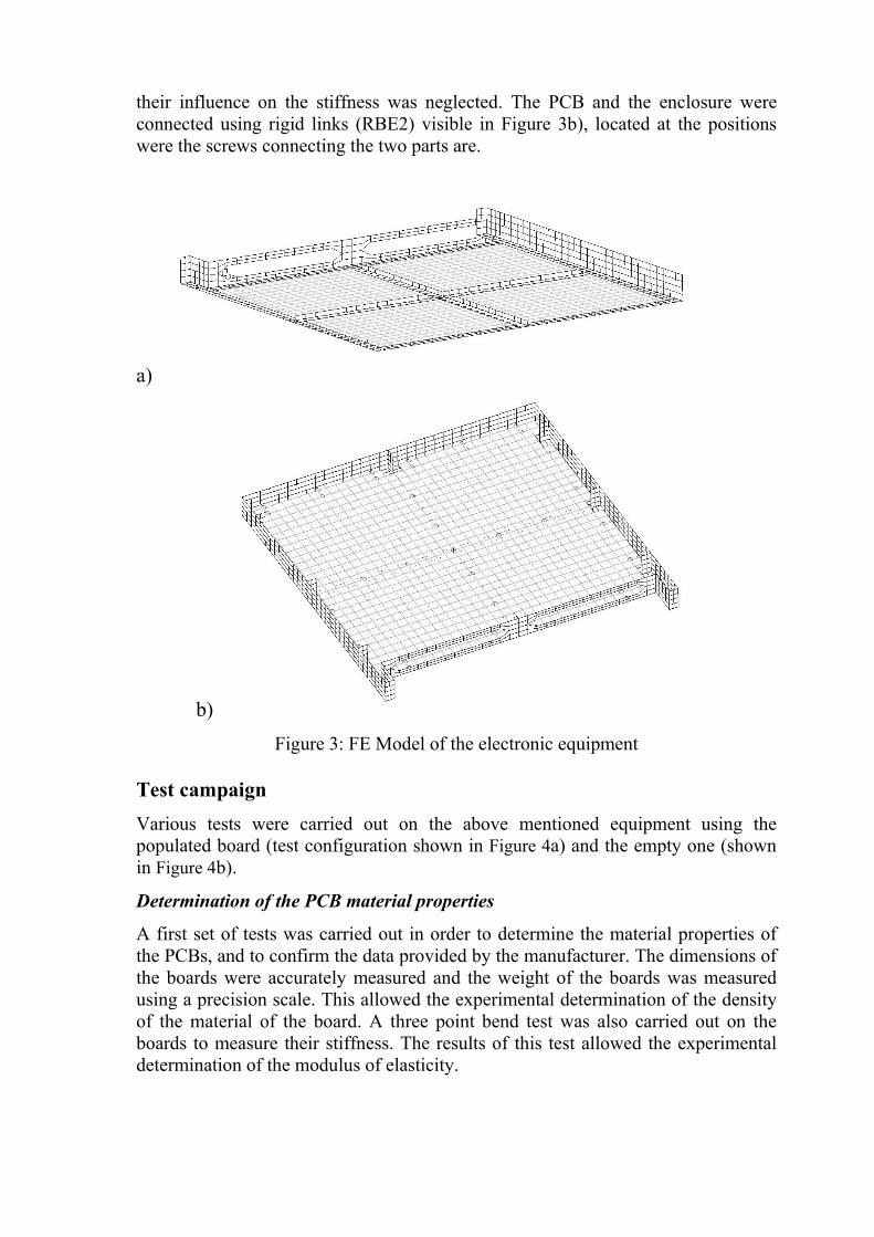
their influence on the stiffness was neglected. The PCB and the enclosure were connected using rigid links (RBE2) visible in Figure 3b), located at the positions were the screws connecting the two parts are.
a)
b) Figure 3: FE Model of the electronic equipment
Test campaign Various tests were carried out on the above mentioned equipment using the populated board (test configuration shown in Figure 4a) and the empty one (shown in Figure 4b).
Determination of the PCB material properties
A first set of tests was carried out in order to determine the material properties of the PCBs, and to confirm the data provided by the manufacturer. The dimensions of the boards were accurately measured and the weight of the boards was measured using a precision scale. This allowed the experimental determination of the density of the material of the board. A three point bend test was also carried out on the boards to measure their stiffness. The results of this test allowed the experimental determination of the modulus of elasticity.

a)
b)
Figure 4: Vibration tests a) populated PCB b) empty PCB
Finally the boards were suspended using low stiffness wire and excited using an impact hammer. This allowed the experimental determination of the resonance frequencies (which agreed well with the results of the FE analysis thus confirming the material data) and damping to be used in the FE evaluation of the vibration response.
Dynamic tests
During these tests, the PCBs assembled in the enclosure were subjected to a typical random vibration environment. The aim of these tests was to retrieve the acceleration response at various locations (on the PCB and on the anti vibration frame) and to compare them with the FE calculations. The tests were carried out
using an electrodynamic shaker at the University of Southampton. The assembly was mounted on the shaker head expansion (aluminium disk of 30 mm thickness) as shown in Figure 4.
a) 0.01
0.1
1
10
10010 100 1000 10000
Exp InputExp AVFExp PCBFE InputFE PCBFE AVF
b) 0.01
0.1
1
10
10010 100 1000 10000
Exp InputExp AVFExp PCBFE AVFFE PCBFE Input
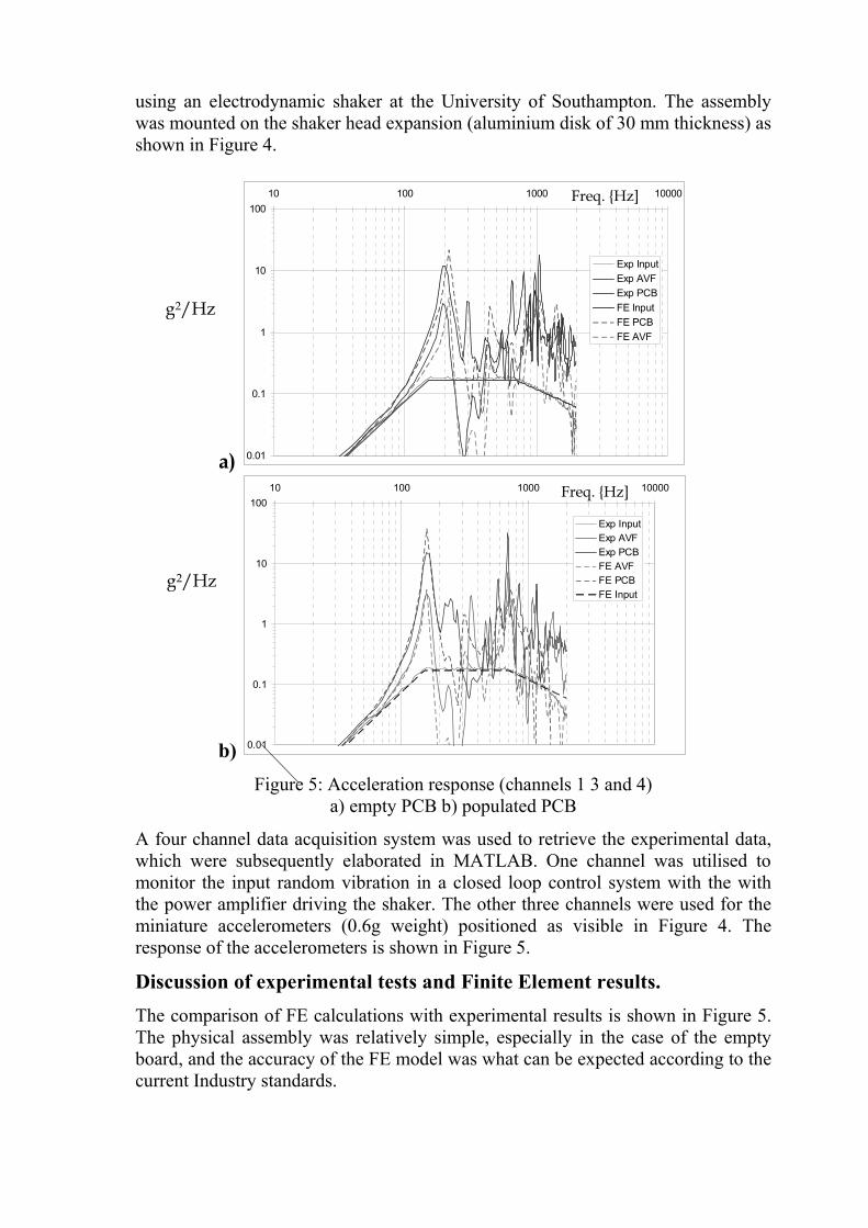
Figure 5: Acceleration response (channels 1 3 and 4)
a) empty PCB b) populated PCB A four channel data acquisition system was used to retrieve the experimental data, which were subsequently elaborated in MATLAB. One channel was utilised to monitor the input random vibration in a closed loop control system with the with the power amplifier driving the shaker. The other three channels were used for the miniature accelerometers (0.6g weight) positioned as visible in Figure 4. The response of the accelerometers is shown in Figure 5.
Discussion of experimental tests and Finite Element results. The comparison of FE calculations with experimental results is shown in Figure 5. The physical assembly was relatively simple, especially in the case of the empty board, and the accuracy of the FE model was what can be expected according to the current Industry standards.
g2/Hz
Freq. {Hz]
g2/Hz
Freq. {Hz]
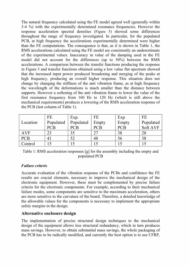
The natural frequency calculated using the FE model agreed well (generally within 3-4 %) with the experimentally determined resonance frequencies. However the response acceleration spectral densities (Figure 5) showed some differences throughout the range of frequency investigated. In particular, for the populated PCB, at high frequency the accelerations experimentally determined were higher than the FE computations. The consequence is that, as it is shown in Table 1, the RMS accelerations calculated using the FE model are consistently an underestimate of the experimental values. Inaccuracy in value of the damping used in the FE model did not account for the differences (up to 50%) between the RMS accelerations. A comparison between the transfer functions producing the response in Figure 5 and transfer functions obtained using a low value flat spectrum showed that the increased input power produced broadening and merging of the peaks at high frequency, producing an overall higher response. This situation does not change by changing the stiffness of the anti vibration frame, as at high frequency the wavelength of the deformations is much smaller than the distance between supports. However a softening of the anti vibration frame to lower the value of the first resonance frequency from 160 Hz to 120 Hz (which is still above the mechanical requirements) produces a lowering of the RMS acceleration response of the PCB (last column of Table 1). Location
FE Populated PCB
Exp. Populated PCB
FE Empty PCB
Exp Empty PCB
FE Populated Soft AVF
AVF 23 35 27 38 28 PCB 41 52 48 56 38 Control 15 15 15 15 15
Table 1: RMS acceleration responses [g] for the assembly including the empty and populated PCB
Failure criteria
Accurate evaluation of the vibration response of the PCBs and confidence the FE results are crucial elements, necessary to improve the mechanical design of the electronic equipment. However, these must be complemented by precise failure criteria for the electronic components. For example, according to their mechanical failure modes, some components are sensitive to the maximum acceleration, others are more sensitive to the curvature of the board. Therefore, a detailed knowledge of the allowable values for the components is necessary to implement the appropriate safety margins in the design.
Alternative enclosure design The implementation of precise structural design techniques to the mechanical design of the equipment allows less structural redundancy, which in turn produces mass savings. However, to obtain substantial mass savings, the whole packaging of the PCB has to be radically modified, and currently the best option is to use CFRP,

instead of standard Aluminium alloys, for the design of the enclosure. As shown in [15], the whole enclosure can be built as an assembly of CFRP honeycomb panels. Another improvement that can be implemented in the enclosure is to substitute the Anti Vibration Frames with Anti Vibration Rods. These directly connect the PCB with the lids of the enclosure, and therefore rely on the out of plane stiffness of the lids. (The lids of conventional Aluminium enclosures are often to thin for this function, hence the use of frames). Two other advantages in the use of AVR are that the first resonance frequency of the boards can be easily measured with an accelerometer positioned externally on the lid, close to the AVR fixing, and that the AVR can act as a very short conductive heath path from hot points of the boards to the lids, which are directly in contact with the structure. More details can be found in [16].
Conclusions In this paper attention is focussed on the mechanical analysis and testing of a typical enclosure for electronics for space application subjected to a random vibration environment representative of a spacecraft launch. In particular the dynamic response of the Printed Circuit Boards (PCBs) within the enclosure is investigated using the Finite Element Method and experimental tests. The comparison between theoretical predictions and experimental results show that although there is a reasonable agreement between resonance frequencies, the theoretical model underestimates the overall rms acceleration on the board. The advantages in changing the enclosure design using CFRP instead of Aluminium Alloy and anti vibration rods instead of anti vibration frames are also briefly discussed.
Acknowledgments The authors would like to thank Surrey Satellite Technology LTD, and EPSRC (GR/N3458101) for their support.
References [1] De Aragon AM, Mura F, Dionisio C, Howes S, Slim R, and Erickson PD,
Future satellite services, concepts and technologies, European Space Agency Bulletin- (95): 99-107 Aug 1998.
[2] J.R. Gaier, W.C. Hardebeck, J.R.T. Bunch, M.L. Davidson, D.B. Beery, Effect of Intercalation in Graphite Epoxy Composites on the Shielding of High Energy Radiations, Journal of Material Research 13 (8), 1998.
[3] Timmis A.R., 1971, A Study of First Day Space Malfunctions, NASA TN D-6474.
[4] Hain H.L., and Patel B.M., 1979, Improved Printed-Circuit Board Dynamics Characteristics Using Structural Damping Ribs, Proceedings of the NAECON 1971, IEEE, New York, USA, pp.222-232.
[5] Steinberg D.S., 1973, Vibration Analyses for Electronic Equipment, John Wiley and Son, NY.

[6] Various Authors, 1995, Structural Materials Handbook, European Space
Agency - Procedures Standards and Specifications 03-203, Polymer Composites and New Advanced Materials - Vol 1 and 2.
[7] Laura P.A.A., Ercoli L., and., 1995, Dynamic Stiffening of a Printed Circuit Board, Acustica, Vol. 81, pp 196-197.
[8] La Malfa S., Laura P.A.A., Rossit C.A., and Alvarez O., 2000, Use of a Dynamic Absorber in the case of a Vibrating Printed Circuit Board of Complicated Boundary Shape, Journal of Sound and Vibration, Vol. 230(3), pp.721-724.
[9] Ong J.H., and Lim G.H., A Simple Technique for Maximising the Fundamental Frequency of Vibrating Structures, ASME Journal of Electronic Packaging, Vol. 122, No 4, pp. 341-349, 2000.
[10] Wong T-L, Stevens K.K., and Wang G., Experimental Modal Analysis and Dynamics Response Prediction of PC Boards With Surface Mounted Electronic Components, ASME Journal of Electronic Packaging, Vol. 113, pp. 244-249, 1999.
[11] Suhir E., Predicted Fundamental Frequency of Vibration of a Heavy Electronic Component Mounted on a Printed Circuit Board, ASME Journal of Electronic Packaging, Vol. 122, No 1, pp. 3-5, 2000.
[12] Lim G.H., Ong J.H, and Penny J.E.T., Effect of Edge and Internal Point Support of a Printed Circuit Board Under Vibration, ASME Journal of Electronic Packaging, Vol. 121, No 2, pp. 122-126, 1999.
[13] Steinberg D.S., Vibration Analysis for Electronic Equipment, John Wiley & Sons, 2000.
[14] Royzman V, Nester E, The dynamic effects and shocks in electronics, 6th International Conference of CADSM 2001, FEB 12-17, 2001, Experience of designing and application of cad systems in microelectronics, 256-259, 2001.
[15] Aglietti G.S., Wicks A. and Barrington-Brown A.J., 1999, Development of the MiniSIL Structural design, Journal of Aerospace Engineering, Vol 213 part G, ISSN 0954-4100, pp. 255-263.
[16] G.S.Aglietti, A Lighter Enclosure for Electronics for Space Applications, Journal of Aerospace Engineering, part G Vol 216-3, pp 131-142, 2002.
[17] G.S. Aglietti, On the use of anti-vibration devices for PCBs in Space Application, submitted to the ASME Journal of Electronic Packaging in April 2001, Accepted in October 2002 currently in print.