Embed Size (px)
Citation preview
Purdue UniversityPurdue e-Pubs
International Compressor Engineering Conference School of Mechanical Engineering
2014
Analysis of a Twin Screw Expander for ORCSystems using Computational Fluid Dynamicswith a Real Gas ModelIva PapesGhent University, Belgium, [email protected]
Joris DegrooteGhent University, Belgium, [email protected]
Jan VierendeelsGhent University, Belgium, [email protected]
Follow this and additional works at: http://docs.lib.purdue.edu/icec
This document has been made available through Purdue e-Pubs, a service of the Purdue University Libraries. Please contact [email protected] foradditional information.Complete proceedings may be acquired in print and on CD-ROM directly from the Ray W. Herrick Laboratories at https://engineering.purdue.edu/Herrick/Events/orderlit.html
Papes, Iva; Degroote, Joris; and Vierendeels, Jan, "Analysis of a Twin Screw Expander for ORC Systems using Computational FluidDynamics with a Real Gas Model" (2014). International Compressor Engineering Conference. Paper 2350.http://docs.lib.purdue.edu/icec/2350

1478, Page 1
22nd
International Compressor Engineering Conference at Purdue, July 14-17, 2014
Analysis of a Twin Screw Expander for ORC Systems using Computational Fluid
Dynamics with a Real Gas Model
Iva Papes*, Joris Degroote, Jan Vierendeels
Ghent University, Department of Flow, Heat and Combustion Mechanics,
Ghent, 9000, Belgium
E-mail: [email protected]
ABSTRACT
With the increase in energy prices and environmental constraints, recovering the energy from low grade waste heat
presents an important challenge. The Organic Ranke Cycles (ORCs) are widely used, but there is still need to
improve their efficiency (especially for small scale energy production). This paper presents the Computational Fluid
Dynamics (CFD) analysis of a twin screw expander which is used for power generation in an ORC system with
refrigerant R245fa. The deforming mesh motion is handled by an in-house code which generates a block-structured
grid with the help of the solutions of Laplace problems. The properties of refrigerant R245fa are derived from the
Augnier Redlich-Kwong cubic equation of state which is incorporated in the computational model.
From the results of a CFD analysis, the pressure-volume diagram, mass flow rates and power output for different
pressure ratios and different designs were obtained. In order to evaluate the effects of individual clearance gaps on
the performance of the expander, time dependent mass flow diagrams for each of them are provided and studied. It
can be concluded that the influence of the leakage flows increases with decrease in rotational speed or with the
increase in pressure ratio. To avoid losses during the filling, an optimized design of the inlet port is necessary.
1. INTRODUCTION
Small scale ORC systems have a big potential for waste heat recovery. The ORC is named for its use of an organic,
high molecular mass fluid which is characterized by low saturation temperatures. Although these ORC systems are
now well developed, research efforts are increasingly directed towards higher efficiencies and powers.
Thermodynamic machines for the expansion of the organic fluids are the key element for the power generation in
the ORC. The screw expander is a special type of rotary displacement machine, in which two screws rotate inside
two overlapping cylinders. The current generation of screw expanders is in fact designed as compressors used the
other way around.
Moving the mesh surrounding the rotor surfaces is complex and therefore a powerful grid manipulator is necessary
for CFD calculations. In this paper an in-house code presented in Vande Voorde (2004) is used. The validation of
CFD calculations using this grid generator for a twin screw compressor has been reported in Vande Voorde (2005).
Since the validation showed good agreement between the experimental results and CFD calculations, the same
procedure is used in this work, for the simulations of an expander where only the sense of rotation is changed.
Several papers have been published using the zero-dimensional chamber model, based on the ideal gas law and
standard thermodynamic relations for compressors and expanders. Seshaiah (2006) presented a model for twin screw
oil injected compressor and Bruemmer and Hutker (2009, 2012) a model for the expander. Recently, the influence of
the clearance sizes on the performance of a screw expander has been investigated by means of CFD calculations by
Rane (2013). Despite these investigations, there is no detailed analysis of the flow through the clearances as a
function of the rotation angle. Since the leakage flows have a significant influence on screw expander efficiency, it
is of great importance to calculate these flows correctly.
The screw expanders are characterized by a fixed built-in volume ratio , determined by the form of the inlet and
outlet surfaces. Paul (2011) determined the internal pressure ratio as . For the best performance, the built-in
volume ratio should match the operating conditions in order to limit the over- and under-expansion losses. If the
internal volume ratio is too high for a given set of operating conditions, the fluid remains trapped longer than
1478, Page 2
22nd
International Compressor Engineering Conference at Purdue, July 14-17, 2014
necessary, leading to a pressure drop below the discharge pressure (over-expansion). On the contrary, if the internal
volume ratio is too low, the fluid in the chamber remains above the discharge pressure when the discharge/outlet
port starts to open (under-expansion). Therefore, depending on the internal pressure ratio, under- or over-expansion
losses can decrease the efficiency of a screw expander.
Apart from over- and under-expansion, the efficiency of a screw expander is mainly governed by the leakage flows
through the clearances and suction pressure losses. In this paper, the performance of a screw expander is studied for
different pressure ratios and for two different expander designs. The difference between these two designs is
additional injection ports. The leakage flows inside the screw expander and the suction losses are described. Based
on this study, a better expander can be designed.
2. CFD ANALYSIS
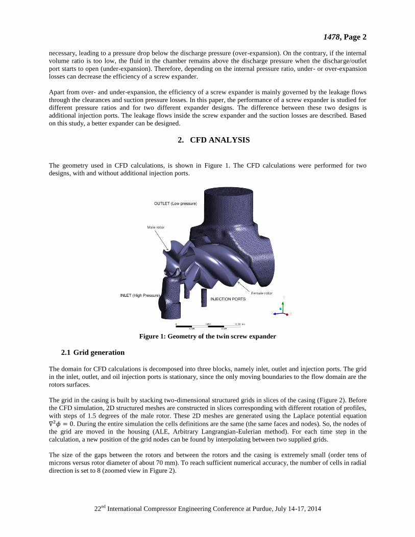
The geometry used in CFD calculations, is shown in Figure 1. The CFD calculations were performed for two
designs, with and without additional injection ports.
Figure 1: Geometry of the twin screw expander
2.1 Grid generation
The domain for CFD calculations is decomposed into three blocks, namely inlet, outlet and injection ports. The grid
in the inlet, outlet, and oil injection ports is stationary, since the only moving boundaries to the flow domain are the
rotors surfaces.
The grid in the casing is built by stacking two-dimensional structured grids in slices of the casing (Figure 2). Before
the CFD simulation, 2D structured meshes are constructed in slices corresponding with different rotation of profiles,
with steps of 1.5 degrees of the male rotor. These 2D meshes are generated using the Laplace potential equation
. During the entire simulation the cells definitions are the same (the same faces and nodes). So, the nodes of
the grid are moved in the housing (ALE, Arbitrary Langrangian-Eulerian method). For each time step in the
calculation, a new position of the grid nodes can be found by interpolating between two supplied grids.
The size of the gaps between the rotors and between the rotors and the casing is extremely small (order tens of
microns versus rotor diameter of about 70 mm). To reach sufficient numerical accuracy, the number of cells in radial
direction is set to 8 (zoomed view in Figure 2).

1478, Page 3
22nd
International Compressor Engineering Conference at Purdue, July 14-17, 2014
Figure 2: Grid in the rotor domain
All blocks are joined together by using sliding interfaces between the rotor domain and stationary grid. The
complete 3D mesh of the twin screw expander consists of 2060515 cells.
2.2 Boundary conditions and simulation parameters
The fluid flow inside the screw expander is compressible and is described by the set of momentum, energy and mass
conservation equations, which are accompanied by the equation of state and the turbulence model. The
governing differential equations are solved by a commercial package with use of user-defined functions to handle
the grid movement and real gas behavior.
The boundary conditions used in calculations for two different designs of the expander are presented in Table 1.
During the simulations, the inlet temperature of the working fluid was . Only the effects of a
variation in the pressure ratio are studied. The spatial discretization that is used for the calculations is first-order
upwind for the convective terms. The temporal discretization is first-order implicit. The solver calculates the
pressure and velocity simultaneously.
Table 1: Boundary conditions and simulation parameters
Design
Evaluated
pressure
ratios
Rotors speed
(male/female)
Boundary
conditions
Turbulence
model Solver
Without additional
injection ports 6, 5, 4 6000/4000
Pressure inlet
Pressure outlet k-ε Coupled
With additional
injection ports 6,5,4,3,2 6000/4000
R245fa is one of the most commonly used fluids in ORC systems with a low temperature heat source. Since the
ideal gas equation of state shows big deviations in the ORC working conditions as presented in Luján (2012), an
appropriate real gas equation of state should be used. In this paper the Aungier Redlich-Kwong equation of state
presented in Aungier (1995) is incorporated in the real gas model through user-defined functions. It represents a
modified form of the Redlich-Kwong equation of state. This new correlation includes an acentric factor and the
critical point compressibility factor as additional parameters to improve its accuracy. The Aungier Redlich-Kwong
equation of state is defined with the following equations:
)(
)(
)~
( 0bVV
Ta
bv
RTp
(1)
Where:
000
0
000
22
00
~,
)(
,08664.0
42747.0,)(,1
cbbVb
bVV
ap
RTc
p
RTb
p
TRa
T
TaTaV
c
cc
c
c
c
c
c
c
n
c
1478, Page 4
22nd
International Compressor Engineering Conference at Purdue, July 14-17, 2014
However, it is important that the flow conditions in every cell are always in the gas phase region. If they fall outside
that region, the partial derivative of pressure at constant temperature with respect to specific volume becomes
positive. Since the mesh motion is complex and the volume of some cells can be extremely small (gap region), this
can cause convergence problems during the start up.
2.3 Geometrical parameters
The configuration of the rotor lobes is 4/6 (male/female). The outer diameter of the male and female rotors is
approximately 70 mm.
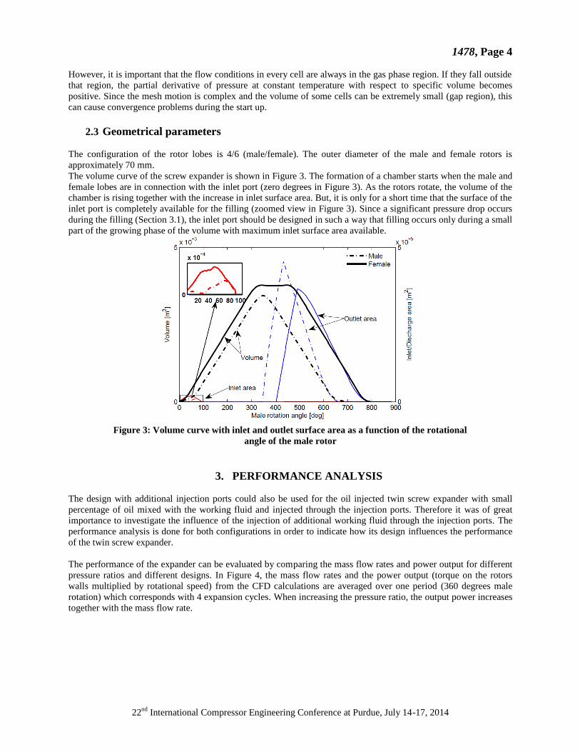
The volume curve of the screw expander is shown in Figure 3. The formation of a chamber starts when the male and
female lobes are in connection with the inlet port (zero degrees in Figure 3). As the rotors rotate, the volume of the
chamber is rising together with the increase in inlet surface area. But, it is only for a short time that the surface of the
inlet port is completely available for the filling (zoomed view in Figure 3). Since a significant pressure drop occurs
during the filling (Section 3.1), the inlet port should be designed in such a way that filling occurs only during a small
part of the growing phase of the volume with maximum inlet surface area available.
Figure 3: Volume curve with inlet and outlet surface area as a function of the rotational
angle of the male rotor
3. PERFORMANCE ANALYSIS
The design with additional injection ports could also be used for the oil injected twin screw expander with small
percentage of oil mixed with the working fluid and injected through the injection ports. Therefore it was of great
importance to investigate the influence of the injection of additional working fluid through the injection ports. The
performance analysis is done for both configurations in order to indicate how its design influences the performance
of the twin screw expander.
The performance of the expander can be evaluated by comparing the mass flow rates and power output for different
pressure ratios and different designs. In Figure 4, the mass flow rates and the power output (torque on the rotors
walls multiplied by rotational speed) from the CFD calculations are averaged over one period (360 degrees male
rotation) which corresponds with 4 expansion cycles. When increasing the pressure ratio, the output power increases
together with the mass flow rate.

1478, Page 5
22nd
International Compressor Engineering Conference at Purdue, July 14-17, 2014
Figure 4: Power vs. Mass Flow Rate at different filling pressures and two different designs
3.1 Pressure-Volume Diagram
P-V diagrams for different pressure ratios and two different designs are presented in Figure 5 and Figure 6.
Figure 5: P-V diagram of the expansion process (design with additional injection ports)
In both figures, only a female working chamber is represented. Looking from the high pressure side, fluid starts to
fill an expanding chamber formed between the lobes of the rotor profiles and the casing of the expander. Since it is
only for a short time that the inlet is completely open for working fluid to enter the working chamber (Figure 3),
throttling losses and a pressure drop will occur (first pressure drop in a P-V diagram). Closing of the inlet (decrease
in inlet surface area) in connection with the increase in volume of the chamber will cause the so called pre-
expansion (second pressure drop in a P-V diagram). Once the chamber is disconnected from the inlet the volume
increases until the maximum volume is reached. Addition of the working fluid through the injection ports will cause
an increase in pressure in a chamber, despite it's increasing volume. This affects the slope of the P-V curve. As the
chamber meets the outlet port, the fluid in the chamber is discharged. Depending on the pressure ratio, over- or
under-expansion can be seen (e.g. for pressure ratio 2 and pressure ratio 6, respectively).

1478, Page 6
22nd
International Compressor Engineering Conference at Purdue, July 14-17, 2014
Figure 6: P-V diagram of the expansion process (design without additional injection ports)
Comparing Figure 5 and Figure 6, it can be seen that with additional injection of the working fluid, the slope of the
P-V curve can be changed in a way that it overcomes the over- and under-expansion losses.
3.2 Leakage analysis
In this paper special focus is on a study of mass flow rates through the clearances which are forming leakage paths.
Depending on the internal pressure ratio, leakage flows from adjacent chambers can cause re-filling and
consequently, affect the volumetric efficiency of the expander as reported in Rane (2011). On the other hand, during
the suction, inlet throttling occurs because the inlet surface is blocked by the tips of the rotor and the filling is
reduced, which will decrease the volumetric efficiency. Therefore, it is paramount that these leakage flows are
assessed correctly.
In the twin screw expander there are four types of leakage paths. It is possible to identify every one of them as it is
shown in Figure 7:
1. Clearances between the rotor tips and the housing allow the flow between two adjacent chambers with different
pressures (mtip in Figure 7).
2. Between the meshing rotors, a sealing line is formed, where leaking occurs (msealing in Figure 7).
3. Blowholes are triangular gaps that are formed at the cusps between two rotors and the housing (mblowhole in Figure
7). Because of manufacturing reasons, it is impossible to have a sealing line that reaches to the cusp of the housing.
As a consequence, when looking at a 2D cross section at the end of the sealing line, a triangular region (blowhole) is
formed between this end and the nearest positions of the tip clearances between both rotors and the housing.
4. Leaks through the clearances at the end planes occur both on the inlet and outlet side (mend plane in Figure 7).

1478, Page 7
22nd
International Compressor Engineering Conference at Purdue, July 14-17, 2014
Figure 7: Different leakages during the expansion process
In this paper the focus was only on tip and sealing leakage flows. The total mass flow rates in Figure 8 and Figure 9
are the sum of all mass flows that are going through the leading and trailing clearances of the working chamber on
the female side (Figure 7).
Figure 8: Leakage flows through (a) tip and (b) sealing clearance gaps (design with additional injection ports)
With an increase in pressure ratio, the internal leakage flows are rising, as depicted in Figure 8 and Figure 9. In these
figures, a positive value means that the flow is leaving the current chamber. During the filling (until 80 degrees of
male rotation), the outflows via both leakage paths are rising. During the expansion, the inflow through clearances
increases, since the pressure in an adjacent chamber (which in this moment is connected with the inlet) is higher. If
in this moment, additional working fluid is injected through injection ports (Figure 8 (a)), the outflow through
clearances will increase. After the chamber is connected with the outlet, two cases are possible. In the case of high
pressure ratios (between and ), the inflow is dominating (since the pressure in the adjacent
chamber is still much higher than at the outlet port). In the case of over-expansion with imposed pressure of
at the inlet, the outflow will increase (since the pressure in the adjacent chamber is lower than the
pressure at the outlet port).

1478, Page 8
22nd
International Compressor Engineering Conference at Purdue, July 14-17, 2014
Figure 9: Leakage flows through (a) tip and (b) sealing clearance gaps (design without additional injection
ports)
3.3 Influence of rotational speed on mass flow through clearances
The variation of the rotational speed has a significant influence on the performance of the twin screw expander.
Ideally, the output power should rise linearly with the rotational speed. However, with increase of the rotational
speed, the time for filling decrease and throttling losses rise. Therefore there is a small decline (comparing to an
ideal linear rise) in output power for higher rotational speed.
Figure 10: Power vs. Mass Flow Rate at different rotational speed with pressure ratio 6, and for the design
with additional injection ports
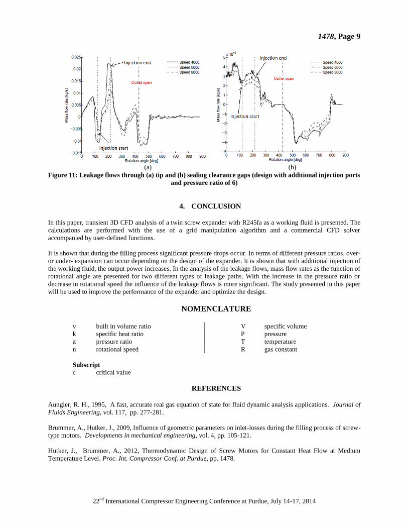
The influence of the leakages is also affected by a change in rotational speed. In Figure 11, the mass flow rates for
two types of leakages and for different rotational speeds are presented. It can be concluded, that with a decrease in
the rotation speed the influence of the leakage flows is higher.
1478, Page 9
22nd
International Compressor Engineering Conference at Purdue, July 14-17, 2014
(a) (b)
Figure 11: Leakage flows through (a) tip and (b) sealing clearance gaps (design with additional injection ports
and pressure ratio of 6)
4. CONCLUSION
In this paper, transient 3D CFD analysis of a twin screw expander with R245fa as a working fluid is presented. The
calculations are performed with the use of a grid manipulation algorithm and a commercial CFD solver
accompanied by user-defined functions.
It is shown that during the filling process significant pressure drops occur. In terms of different pressure ratios, over-
or under- expansion can occur depending on the design of the expander. It is shown that with additional injection of
the working fluid, the output power increases. In the analysis of the leakage flows, mass flow rates as the function of
rotational angle are presented for two different types of leakage paths. With the increase in the pressure ratio or
decrease in rotational speed the influence of the leakage flows is more significant. The study presented in this paper
will be used to improve the performance of the expander and optimize the design.
NOMENCLATURE
v built in volume ratio
k specific heat ratio
π pressure ratio
n rotational speed
V specific volume
P pressure
T temperature
R gas constant
Subscript
c critical value
REFERENCES
Aungier, R. H., 1995, A fast, accurate real gas equation of state for fluid dynamic analysis applications. Journal of
Fluids Engineering, vol. 117, pp. 277-281.
Brummer, A., Hutker, J., 2009, Influence of geometric parameters on inlet-losses during the filling process of screw-
type motors. Developments in mechanical engineering, vol. 4, pp. 105-121.
Hutker, J., Brummer, A., 2012, Thermodynamic Design of Screw Motors for Constant Heat Flow at Medium
Temperature Level. Proc. Int. Compressor Conf. at Purdue, pp. 1478.

1478, Page 10
22nd
International Compressor Engineering Conference at Purdue, July 14-17, 2014
Fujiwara, M., Osada, Y., 1995, Performance analysis of an oil-injected screw compressor and its application.
International Journal of Refrigeration, Number 4, vol. 18, pp. 220-227.
Luján, J.M., Serrano, J.R., Dolz, V., Sánchez, J., 2012, Model of the expansion process for R245fa in an Organic
Rankine Cycle (ORC). Applied Thermal Engineering, vol. 40, pp. 248-257.
Paul, C. H., 2011, Compressors Hand Book, McGraw Hill.
Kovacevic, A., Rane, S., 2013, 3D CFD analysis of a twin screw expander, 8th International Conference on
Compressors and their Systems, pp. 417-429, City University London, 9-10 September.
Smith, I.K., Stosic, N., 2006, Cost effective small scale ORC systems for power recovery from low grade heat
sources. Proceedings of ASME International Mechanical Engineering Congress and Exposition, Chicago, Illinois,
USA, pp. 1-7.
Seshaiah, N., Ghosh, S.K., Sahoo, R.K., Sarangi, S.K., 2006, Performance Analysis of Oil Injected Twin Screw
Compressor. 18th National and 7th ISHMT-ASME Heat and Mass Transfer Conference, India.
Vande Voorde, J., Vierendeels, J., Dick, E., 2004, Development of a Laplacian-based mesh generator for ALE
calculations in rotary volumetric pumps and compressors. Computer Methods in Applied Mechanics and
Engineering, vol. 193, 39-41, pp. 4401-4415.
Vande Voorde, J., Vierendeels, J. and Dick, E., 2005, ALE Calculations of Flow Through Rotary Positive
Displacement Machines. In Proc. of the ASME Fluids Engineering Divison Summer Meeting and Exhibition,
FEDSM2005-77353, ISBN 0-7918-3760-2, Huston, USA.
ACKNOWLEDGEMENT
This study is part of the ORCNext project with financial support of IWT Flanders. This work was carried out using
the STEVIN Supercomputer Infrastructure at Ghent University, funded by Ghent University, the Flemish
Supercomputer Center (VSC), the Hercules Foundation and the Flemish Government (department EWI). J. Degroote
gratefully acknowledges a post-doc fellowship of the Research Foundation Flanders (FWO).


![Investigating a Small Oil-Flooded Twin-Screw Expander for ......expander without timing gears in [12,13]. Kliem [14] investigated a screw expander application in a trilateral flash](https://img.dokumen.tips/doc/110x75/5f40f88392a7a5666c2afab0/investigating-a-small-oil-flooded-twin-screw-expander-for-expander-without.jpg)