Embed Size (px)
Citation preview
351
Analysis-by-S17. Analysis-by-Synthesis Speech Coding
J.-H. Chen, J. Thyssen
Since the early 1980s, advances in speech cod-ing technologies have enabled speech codersto achieve bit-rate reductions of a factor of 4to 8 while maintaining roughly the same highspeech quality. One of the most important drivingforces behind this feat is the so-called analysis-by-synthesis paradigm for coding the excitationsignal of predictive speech coders. In this chap-ter, we give an overview of many variations of theanalysis-by-synthesis excitation coding paradigmas exemplified by various speech coding standardsaround the world. We describe the variations ofthe same basic theme in the context of differ-ent coder structures where these techniques areemployed. We also attempt to show the rela-tionship between them in the form of a familytree. The goal of this chapter is to give the read-ers a big-picture understanding of the dominanttypes of analysis-by-synthesis excitation codingtechniques for predictive speech coding.
17.1 Overview.............................................. 352
17.2 Basic Conceptsof Analysis-by-Synthesis Coding ............ 35317.2.1 Definition of Analysis-by-Synthesis 35317.2.2 From Conventional
Predictive Waveform Codingto a Speech Synthesis Model .......... 353
17.2.3 Basic Principleof Analysis by Synthesis ................ 354
17.2.4 Generic Analysis-by-SynthesisEncoder Structure ......................... 355
17.2.5 Reasons for the Coding Efficiencyof Analysis by Synthesis ................ 357
17.3 Overview of ProminentAnalysis-by-Synthesis Speech Coders...... 357
17.4 Multipulse Linear Predictive Coding(MPLPC) ................................................ 360
17.5 Regular-Pulse Excitationwith Long-Term Prediction (RPE-LTP) ..... 362
17.6 The Original Code ExcitedLinear Prediction (CELP) Coder ................ 363
17.7 US Federal Standard FS1016 CELP............. 367
17.8 Vector Sum ExcitedLinear Prediction (VSELP) ....................... 368
17.9 Low-Delay CELP (LD-CELP) ...................... 370
17.10 Pitch SynchronousInnovation CELP (PSI-CELP) ..................... 371
17.11 Algebraic CELP (ACELP) ........................... 37117.11.1 ACELP Background ........................ 37217.11.2 ACELP Efficient Search Methods ...... 37317.11.3 ACELP in Standards ....................... 377
17.12 Conjugate Structure CELP (CS-CELP)and CS-ACELP ....................................... 377
17.13 Relaxed CELP (RCELP) –Generalized Analysis by Synthesis .......... 37817.13.1 Generalized Analysis by Synthesis
Applied to the Pitch Parameters ..... 37817.13.2 RCELP in Standards ....................... 381
17.14 eX-CELP ............................................... 38117.14.1 eX-CELP in Standards .................... 382
17.15 iLBC ..................................................... 382
17.16 TSNFC ................................................... 38317.16.1 Excitation VQ in TSNFC ................... 38517.16.2TSNFC in Standards ....................... 386
17.17 Embedded CELP .................................... 386
17.18 Summary of Analysis-by-SynthesisSpeech Coders ...................................... 388
17.19 Conclusion ........................................... 390
References .................................................. 390
PartC
17
352 Part C Speech Coding
17.1 Overview
Historically, speech coding technology has been dom-inated by coders based on linear prediction. Toachieve good speech quality, most speech codingstandards are waveform-approximating coders (or wave-form coders for short), and the majority use linearprediction to exploit the redundancy in the speechwaveform.
Of course, the techniques in speech coding stan-dards are not the only ones available, as there are manyother speech coding techniques proposed in the liter-ature that have not been used in standards. However,speech coding standards represent the dominant andmost widely deployed speech coding techniques. Oftenthey also include the best-performing techniques for thegiven requirements of bit rate, coding delay, and codeccomplexity at the time they were standardized. There-fore, it is useful to examine some of the techniquesin speech coding standards to see how the dominantspeech coding techniques have evolved over the years.For a comprehensive review of speech coding standardsup to about 1995, see [17.1].
The first speech coding standard based on predictivewaveform coding is probably 32 kb/s adaptive differ-ential pulse code modulation (ADPCM), which wasinitially standardized by the Comité Consultatif Inter-national Téléphonique et Télégraphique (CCITT, thepredecessor of the ITU-T) as recommendation G.721in 1984 and later modified and restandardized as partof G.726 in 1986. The G.726 standard is a narrow-band(telephone-bandwidth) speech coder with an input sam-pling rate of 8 kHz and encoding bit rates of 16, 24, 32,and 40 kb/s, with 32 kb/s being the most widely usedbit rate of G.726.
The basic idea of the G.726 ADPCM coder is to usean adaptive linear predictor to predict the input speechsignal, and then use an adaptive scalar quantizer toquantize the difference signal between the input speechand the predicted version. Since statistically this differ-ence signal tends to be smaller than the input speechsignal, one can use a lower bit rate to quantize the differ-ence signal to the same precision as direct quantizationof the speech signal itself. This is how predictive codersachieve bit-rate reduction through the use of predic-tion to exploit the redundancy between nearby speechsamples. The difference signal is often called the pre-diction residual signal, because it is the residual of thespeech signal after the predictable portion is removed. Inanalysis-by-synthesis speech coders, this prediction re-sidual signal is often referred to as the excitation signal.
The reason will become clear during later discussions inthis chapter.
In 1982, at about the same time that G.721ADPCM was being developed, Atal and Remde pro-posed the first analysis-by-synthesis speech waveformcoding technique called multipulse linear predictivecoding (MPLPC) [17.2]. This work led to Atal andSchroeder’s 1984 proposal of another analysis-by-synthesis speech coding technique called stochasticcoding [17.3], which was renamed code-excited lin-ear prediction (CELP) [17.4] in 1985. From then on,CELP became the dominant speech coding techniquefor the next two decades, with hundreds or perhaps eventhousands of technical papers published on variations ofCELP techniques.
Due to their high coding efficiency, variations ofCELP coding techniques together with other advance-ments have enabled speech waveform coders to halvethe bit rate of 32 kb/s G.726 ADPCM three times whilemaintaining roughly the same speech quality. This is ev-idenced by the ITU-T’s speech coding standardizationeffort after standardizing 32 kb/s ADPCM in 1984.
The first halving of bit rate to 16 kb/s happenedwith the ITU-T G.728 low-delay CELP (LD-CELP)coder [17.5, 6]. At the cost of increasing the bufferingdelay from one to five samples (0.625 ms at 8 kHz sam-pling rate), the G.728 coder halved the bit rate of 32 kb/sG.726 ADPCM while maintaining equivalent or betterspeech quality for all conditions tested.
The second halving of bit rate to 8 kb/s happenedwith the ITU-T G.729 conjugate-structure algebraicCELP (CS-ACELP) [17.7]. At the cost of increasingthe buffering delay further to 80 samples of frame sizeplus 40 samples of look-ahead (or 15 ms total), the G.729coder halved the bit rate again to 8 kb/s while maintain-ing the speech quality for most test conditions excepttandeming and speech in background noise.
The third halving of bit rate to 4 kb/s happened withcandidate coders [17.8, 9] submitted for the ITU-T’s4 kb/s speech coding standardization. A promising can-didate 4 kb/s coder [17.8] was based on CELP. Althoughthe ITU-T eventually did not standardize a 4 kb/s coder,this CELP-based candidate coder did achieve equivalentspeech quality as 32 kb/s G.726 ADPCM at least forclean speech conditions at the cost of further increasingthe buffering delay to 30–35 ms.
Of course, the G.728, G.729, and ITU-T 4 kb/scandidate coders are merely three example coders thathelp to make a point that the analysis-by-synthesis
PartC
17.1
Analysis-by-Synthesis Speech Coding 17.2 Basic Concepts of Analysis-by-Synthesis Coding 353
speech coding technique was the main driving forcebehind the feat of reducing the bit rate by a factor of4 to 8 within two decades while maintaining equiva-lent speech quality, at least for clean speech. In thelast two decades, researchers have proposed numer-ous other speech waveform coders in the bit-rate rangeof 4–16 kb/s that achieve speech quality equivalent toor better than the speech quality of the 32 kb/s G.726ADPCM coder. The vast majority of these are analysis-by-synthesis speech coders based on either CELP orMPLPC. Therefore, it is fair to say that analysis-by-synthesis is undeniably the most important speechcoding method in modern low-bit-rate speech waveformcoding.
The main emphasis of this chapter is to describemany of the major flavors of analysis-by-synthesis ex-citation coding for linear predictive speech waveformcoders, as exemplified by various speech coding stan-dards around the world. Due to the space limitation, it isnot possible to cover all speech coding standards or evenall aspects of the standards discussed in this chapter.Readers interested in learning more about other as-
pects of analysis-by-synthesis speech coders are referredto [17.10].
The rest of this chapter is organized as follows.Section 17.2 describes the basic concepts of the analysis-by-synthesis paradigm in the context of speech coding.Section 17.3 gives an overview of the different flavorsof analysis-by-synthesis excitation coding and showsthe relationship between them in the form of a fam-ily tree. Sections 17.4–17.17 then provide somewhatmore-detailed descriptions of these different flavors ofanalysis-by-synthesis speech coders one-by-one, includ-ing MPLPC, original CELP, regular-pulse excitation(RPE), federal standard 1016 (FS1016) CELP, vectorsum excited linear prediction (VSELP), LD-CELP, pitchsynchronous innovation CELP (PSI-CELP), ACELP,CS-ACELP, relaxed CELP (RCELP), extended CELP(eX-CELP), forward backward linear predictive coding(FB-LPC), two-stage noise feedback coding (TSNFC),and embedded CELP, roughly in a chronological order.Section 17.18 summarizes these analysis-by-synthesisspeech coders in a table format. Finally, Sect. 17.19concludes this chapter.
17.2 Basic Concepts of Analysis-by-Synthesis Coding
17.2.1 Definition of Analysis-by-Synthesis
What exactly is analysis-by-synthesis? The phrase“analysis-by-synthesis” can be traced back to at least1959 in a paper by Halle and Stevens [17.11]. In another1961 paper by Bell et al. [17.12], a detailed definition ofanalysis-by-synthesis is given as follows:
The term analysis-by-synthesis is used to refer to anactive analysis process that can be applied to signalsthat are produced by a generator whose propertiesare known. The heart of an analysis-by-synthesissystem is a signal generator capable of synthesizingall and only the signals to be analyzed. The signalssynthesized by the generator are compared with thesignals to be analyzed, and a measure of error iscomputed. Different signals are generated until oneis found that causes the error to reach some small-est value, at which time the analyzer indicates theproperties of the internally generated signal.
Although this definition was given four and a halfdecades ago in a paper discussing the subject of speechanalysis, it is still equally valid today as a description ofthe basic concepts behind analysis-by-synthesis speechwaveform coding.
17.2.2 From ConventionalPredictive Waveform Codingto a Speech Synthesis Model
To understand analysis-by-synthesis speech waveformcoding, it is useful to look first at conventional predic-tive speech waveform coding. In conventional predictivespeech coders based on linear prediction, the predictionis typically performed using a weighted sum of previ-ously quantized speech samples rather than unquantizedinput speech samples. This is because the quantizedspeech samples are available at the decoder while the in-put speech samples are not. Performing linear predictionbased on the quantized speech in the encoder enables thedecoder to produce the same predicted speech and trackthe encoder states in the absence of transmission er-rors. Prediction based on previously quantized speechsignal is called closed-loop prediction, while predictionbased on unquantized input speech signal is called open-loop prediction. For in-depth discussion of predictivewaveform coding principles, see [17.13].
The encoder and decoder of the most basic formof closed-loop predictive waveform coding is shownin Fig. 17.1. In the encoder in Fig. 17.1a, the linearpredictor, represented by the transfer function P(z),
PartC
17.2
354 Part C Speech Coding
����������
��
����� �
����� ��� ������
�� ������������������������������������������ ��
�� ������������ �
�� �����������
��������������� ���� ����������
� ���
�� �������������
�� ��������������
�
�� �������������
�� ������������ �
������ ������� ������������
�������������������� ��
!�������"������#$%#�� ���&�� �����������
���� ����������
� ���
��
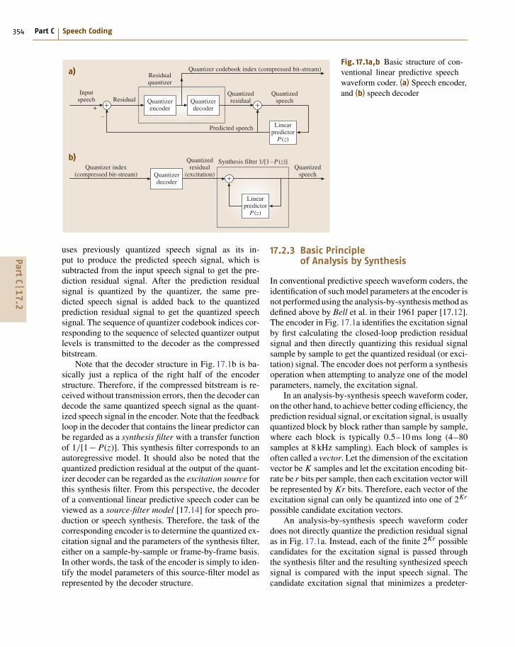
Fig. 17.1a,b Basic structure of con-ventional linear predictive speechwaveform coder. (a) Speech encoder,and (b) speech decoder
uses previously quantized speech signal as its in-put to produce the predicted speech signal, which issubtracted from the input speech signal to get the pre-diction residual signal. After the prediction residualsignal is quantized by the quantizer, the same pre-dicted speech signal is added back to the quantizedprediction residual signal to get the quantized speechsignal. The sequence of quantizer codebook indices cor-responding to the sequence of selected quantizer outputlevels is transmitted to the decoder as the compressedbitstream.
Note that the decoder structure in Fig. 17.1b is ba-sically just a replica of the right half of the encoderstructure. Therefore, if the compressed bitstream is re-ceived without transmission errors, then the decoder candecode the same quantized speech signal as the quant-ized speech signal in the encoder. Note that the feedbackloop in the decoder that contains the linear predictor canbe regarded as a synthesis filter with a transfer functionof 1/[1− P(z)]. This synthesis filter corresponds to anautoregressive model. It should also be noted that thequantized prediction residual at the output of the quant-izer decoder can be regarded as the excitation source forthis synthesis filter. From this perspective, the decoderof a conventional linear predictive speech coder can beviewed as a source-filter model [17.14] for speech pro-duction or speech synthesis. Therefore, the task of thecorresponding encoder is to determine the quantized ex-citation signal and the parameters of the synthesis filter,either on a sample-by-sample or frame-by-frame basis.In other words, the task of the encoder is simply to iden-tify the model parameters of this source-filter model asrepresented by the decoder structure.
17.2.3 Basic Principleof Analysis by Synthesis
In conventional predictive speech waveform coders, theidentification of such model parameters at the encoder isnot performed using the analysis-by-synthesis method asdefined above by Bell et al. in their 1961 paper [17.12].The encoder in Fig. 17.1a identifies the excitation signalby first calculating the closed-loop prediction residualsignal and then directly quantizing this residual signalsample by sample to get the quantized residual (or exci-tation) signal. The encoder does not perform a synthesisoperation when attempting to analyze one of the modelparameters, namely, the excitation signal.
In an analysis-by-synthesis speech waveform coder,on the other hand, to achieve better coding efficiency, theprediction residual signal, or excitation signal, is usuallyquantized block by block rather than sample by sample,where each block is typically 0.5–10 ms long (4–80samples at 8 kHz sampling). Each block of samples isoften called a vector. Let the dimension of the excitationvector be K samples and let the excitation encoding bit-rate be r bits per sample, then each excitation vector willbe represented by Kr bits. Therefore, each vector of theexcitation signal can only be quantized into one of 2Kr
possible candidate excitation vectors.An analysis-by-synthesis speech waveform coder
does not directly quantize the prediction residual signalas in Fig. 17.1a. Instead, each of the finite 2Kr possiblecandidates for the excitation signal is passed throughthe synthesis filter and the resulting synthesized speechsignal is compared with the input speech signal. Thecandidate excitation signal that minimizes a predeter-
PartC
17.2
Analysis-by-Synthesis Speech Coding 17.2 Basic Concepts of Analysis-by-Synthesis Coding 355
!�������������
����������
'����(�����
)����������� ����
������!������������
)���� ����(���� ���
!������"�����
��
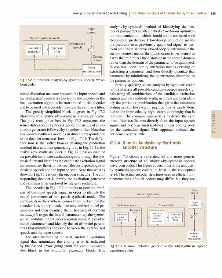
Fig. 17.2 Simplified analysis-by-synthesis speech wave-form coder
mined distortion measure between the input speech andthe synthesized speech is selected by the encoder as thefinal excitation signal to be transmitted to the decoderand to be used in the decoder to excite the synthesis filter.
The greatly simplified block diagram in Fig. 17.2illustrates this analysis-by-synthesis coding principle.The gray rectangular box in Fig. 17.2 represents thesource-filter speech synthesis model, consisting of an ex-citation generator followed by a synthesis filter. Note thatthis speech synthesis model is in direct correspondenceto the decoder structure shown in Fig. 17.1b. The differ-ence now is that rather than calculating the predictionresidual first and then quantizing it as in Fig. 17.1a, theanalysis-by-synthesis coder in Fig. 17.2 passes each ofthe possible candidate excitation signals through the syn-thesis filter and identifies the candidate excitation signalthat minimizes the error between the corresponding syn-thesized speech and the input speech. Note that what isshown in Fig. 17.2 is only the encoder structure. The cor-responding decoder is simply the excitation generatorand synthesis filter enclosed by the gray rectangle.
The encoder in Fig. 17.2 attempts to perform anal-ysis of the input speech signal in order to identify themodel parameters of the speech synthesis model. Thename analysis-by-synthesis comes from the fact that theencoder does not try to calculate unquantized model pa-rameters and then quantize them, but instead performthe analysis to get the model parameters by the synthe-sis of candidate output speech signals using all possiblemodel parameters and identify the set of model param-eters that minimizes the error between the synthesizedspeech and the input speech.
The identification of the best candidate excitationsignal that minimizes the coding error is indicatedby the dashed arrow going from the error minimiza-tion block to the excitation generator block. This
analysis-by-synthesis method of identifying the bestmodel parameters is often called closed-loop optimiza-tion or quantization, which should not be confused withclosed-loop prediction. Closed-loop prediction meansthe predictor uses previously quantized signal to per-form prediction, whereas closed-loop quantization in thecurrent context means the quantization is performed ina way that minimizes the distortion in the speech domainrather than the domain of the parameter to be quantized.In contrast, open-loop quantization means deriving orextracting a parameter and then directly quantize thatparameter by minimizing the quantization distortion inthe parameter domain.
Strictly speaking, a true analysis-by-synthesis coderwill synthesize all possible candidate output speech sig-nals using all combinations of the candidate excitationsignals and the candidate synthesis filters and then iden-tify the particular combination that gives the minimumcoding error. However, in practice this is rarely donedue to the impractically high search complexity that isrequired. The common approach is to derive the syn-thesis filter coefficients directly from the input speechsignal and perform analysis-by-synthesis coding onlyfor the excitation signal. This approach reduces theperformance very little.
17.2.4 Generic Analysis-by-SynthesisEncoder Structure
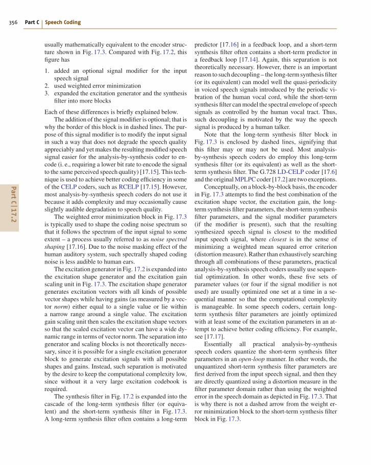
Figure 17.3 shows a more detailed and more genericencoder structure of an analysis-by-synthesis speechwaveform coder. This figure covers most of the analysis-by-synthesis speech coders, at least in the conceptuallevel. The actual encoder structures used in efficient im-plementations of such coders may differ, but they are
������!������������
����������
�(� �����"���
*��(��������
������� ����
)���� �����(���� ��� !�������"�����
)���� ����� ��
(���� ���
)���� ����( �� ���(�����
�!������"��������
����+ ����
���������!������"�����
��
Fig. 17.3 A more detailed generic analysis-by-synthesis speechwaveform coder
PartC
17.2
356 Part C Speech Coding
usually mathematically equivalent to the encoder struc-ture shown in Fig. 17.3. Compared with Fig. 17.2, thisfigure has
1. added an optional signal modifier for the inputspeech signal
2. used weighted error minimization3. expanded the excitation generator and the synthesis
filter into more blocks
Each of these differences is briefly explained below.The addition of the signal modifier is optional; that is
why the border of this block is in dashed lines. The pur-pose of this signal modifier is to modify the input signalin such a way that does not degrade the speech qualityappreciably and yet makes the resulting modified speechsignal easier for the analysis-by-synthesis coder to en-code (i. e., requiring a lower bit rate to encode the signalto the same perceived speech quality) [17.15]. This tech-nique is used to achieve better coding efficiency in someof the CELP coders, such as RCELP [17.15]. However,most analysis-by-synthesis speech coders do not use itbecause it adds complexity and may occasionally causeslightly audible degradation to speech quality.
The weighted error minimization block in Fig. 17.3is typically used to shape the coding noise spectrum sothat it follows the spectrum of the input signal to someextent – a process usually referred to as noise spectralshaping [17.16]. Due to the noise masking effect of thehuman auditory system, such spectrally shaped codingnoise is less audible to human ears.
The excitation generator in Fig. 17.2 is expanded intothe excitation shape generator and the excitation gainscaling unit in Fig. 17.3. The excitation shape generatorgenerates excitation vectors with all kinds of possiblevector shapes while having gains (as measured by a vec-tor norm) either equal to a single value or lie withina narrow range around a single value. The excitationgain scaling unit then scales the excitation shape vectorsso that the scaled excitation vector can have a wide dy-namic range in terms of vector norm. The separation intogenerator and scaling blocks is not theoretically neces-sary, since it is possible for a single excitation generatorblock to generate excitation signals with all possibleshapes and gains. Instead, such separation is motivatedby the desire to keep the computational complexity low,since without it a very large excitation codebook isrequired.
The synthesis filter in Fig. 17.2 is expanded into thecascade of the long-term synthesis filter (or equiva-lent) and the short-term synthesis filter in Fig. 17.3.A long-term synthesis filter often contains a long-term
predictor [17.16] in a feedback loop, and a short-termsynthesis filter often contains a short-term predictor ina feedback loop [17.14]. Again, this separation is nottheoretically necessary. However, there is an importantreason to such decoupling – the long-term synthesis filter(or its equivalent) can model well the quasi-periodicityin voiced speech signals introduced by the periodic vi-bration of the human vocal cord, while the short-termsynthesis filter can model the spectral envelope of speechsignals as controlled by the human vocal tract. Thus,such decoupling is motivated by the way the speechsignal is produced by a human talker.
Note that the long-term synthesis filter block inFig. 17.3 is enclosed by dashed lines, signifying thatthis filter may or may not be used. Most analysis-by-synthesis speech coders do employ this long-termsynthesis filter (or its equivalent) as well as the short-term synthesis filter. The G.728 LD-CELP coder [17.6]and the original MPLPC coder [17.2] are two exceptions.
Conceptually, on a block-by-block basis, the encoderin Fig. 17.3 attempts to find the best combination of theexcitation shape vector, the excitation gain, the long-term synthesis filter parameters, the short-term synthesisfilter parameters, and the signal modifier parameters(if the modifier is present), such that the resultingsynthesized speech signal is closest to the modifiedinput speech signal, where closest is in the sense ofminimizing a weighted mean squared error criterion(distortion measure). Rather than exhaustively searchingthrough all combinations of these parameters, practicalanalysis-by-synthesis speech coders usually use sequen-tial optimization. In other words, these five sets ofparameter values (or four if the signal modifier is notused) are usually optimized one set at a time in a se-quential manner so that the computational complexityis manageable. In some speech coders, certain long-term synthesis filter parameters are jointly optimizedwith at least some of the excitation parameters in an at-tempt to achieve better coding efficiency. For example,see [17.17].
Essentially all practical analysis-by-synthesisspeech coders quantize the short-term synthesis filterparameters in an open-loop manner. In other words, theunquantized short-term synthesis filter parameters arefirst derived from the input speech signal, and then theyare directly quantized using a distortion measure in thefilter parameter domain rather than using the weightederror in the speech domain as depicted in Fig. 17.3. Thatis why there is not a dashed arrow from the weight er-ror minimization block to the short-term synthesis filterblock in Fig. 17.3.
PartC
17.2

Analysis-by-Synthesis Speech Coding 17.3 Overview of Prominent Analysis-by-Synthesis Speech Coders 357
Exactly how many parameter sets should be closed-loop or jointly quantized depends on the coder designgoals and requirements. In some analysis-by-synthesisspeech coders that emphasize low computational com-plexity, only the excitation shape is closed-loopquantized and all other parameter sets are open-loopquantized. As long as the encoding bit rate is not overlylow and the speech coder is carefully designed, evensuch an analysis-by-synthesis coder can achieve fairlyhigh speech quality.
17.2.5 Reasons for the Coding Efficiencyof Analysis by Synthesis
As mentioned earlier, the analysis-by-synthesis excita-tion coding is one of the most efficient speech codingtechniques and is the main driving force behind the 4 to8 times reduction in speech coder bit-rate in the last twodecades. A fundamental question to ask is: why is thisanalysis-by-synthesis technique for predictive speechcoders so powerful? One reason is that the speech syn-thesis model in Fig. 17.3 is a good fit to how speechsignal is produced by a human talker.
Perhaps a more important reason is the analysis-by-synthesis method itself. Think of it this way: the taskof the encoder is to find the quantized parameters ofthis speech synthesis model so that the synthesized out-put speech sounds closest to the input speech. Giventhis, then which other coding method is better than try-ing all possible quantized parameters and see whichone gives an output speech signal closest to the inputspeech signal? This trying all possible values and find-ing which one gives the best output speech is the essenceof analysis-by-synthesis coding. It is a stark contrastto earlier coding methods where the unquantized opti-mal parameter value is first derived and then directlyquantized using a distortion measure in that parameterdomain.
Yet a third reason is that such an analysis-by-synthesis approach naturally lends itself to enable theuse of the so-called vector quantization (VQ) , whichhas a higher coding efficiency than conventional sample-
by-sample scalar quantization as used in ADPCM.Some might argue that ADPCM and adaptive predictivecoding (APC) [17.16] are analysis-by-synthesis coderssince minimizing the quantization error in the predictionresidual domain is mathematically equivalent to mini-mizing the coding error in the speech domain. Whilethere is indeed such a mathematical equivalence in thedegenerate case of scalar quantization, it is question-able, in our opinion, whether ADPCM and APC shouldbe called analysis-by-synthesis coders. Our main objec-tion is that these scalar-quantization-based coders neverreally perform the synthesis operation when trying todo the analysis of the model parameters (i. e., whenperforming residual quantization).
Conventional ADPCM and APC coders are re-stricted to using sample-by-sample scalar quantizationand cannot be extended to vector quantization to reapthe benefit of the higher coding efficiency of VQ. (Ifthese coders indeed use VQ, then they will not becalled ADPCM and APC anymore and will be calledCELP.) These coders need to compute the unquan-tized prediction residual signal first and then quantizeit, but with VQ the unquantized prediction residualsignal depends on the quantized prediction residual sig-nal due to the feedback filter structure in Fig. 17.1a.This creates a chicken-and-egg problem. In contrast, theanalysis-by-synthesis approach completely avoid thischicken-and-egg problem by directly trying all possi-ble quantized residual (excitation) signals without theneed to compute the unquantized residual signal first.Thus, by enabling the use of VQ for the excitation sig-nal, the analysis-by-synthesis approach reaps the benefitof the higher coding efficiency of VQ.
This chapter only explains the most fundamen-tal basic ideas of analysis-by-synthesis coding. If theencoder structure in Fig. 17.3 were implemented asis, the resulting complexity would be quite high. Inlater sections, computationally much more efficient butmathematically equivalent encoder structures will beintroduced. Most analysis-by-synthesis speech coderstoday are implemented based on the more efficientencoder structures.
17.3 Overview of Prominent Analysis-by-Synthesis Speech Coders
This section gives an overview of some prominentanalysis-by-synthesis speech coders and shows therelationship between them in the form of a familytree. There are numerous analysis-by-synthesis speechcoders proposed in the literature. It is not practical
to describe all of them in this chapter. Instead, theintention here is to describe only those analysis-by-synthesis speech coders that are either standard codersor are the first of its kind and thus are definitive andseminal.
PartC
17.3

358 Part C Speech Coding
������#,-.�
/��(�� �������#,-0�
1 2�3��������#,-4�
�����#,-5�
165.-�������#,-,�
3 #7#8�����#,-,�
� �40������#,-,�
�9'�:�� ������#,,;�
)<'������#,,0�
165.,�������
�#,,8�
165.;6#� �46;���$������#,,4�
=�>�)3�����#,,8�
�9'�)3�����#,,8�
1 2�)3�����#,,5�
165.;6#� �86;���$�������#,,4�
<2�*?�����.77.�
165..6.$>2�*?�����.77#�
2<��������.777�
?<#8$?<;.������.77;�
1 2�>2�����#,,,�
165.,6#�������������.778�
��?'�������.77.�
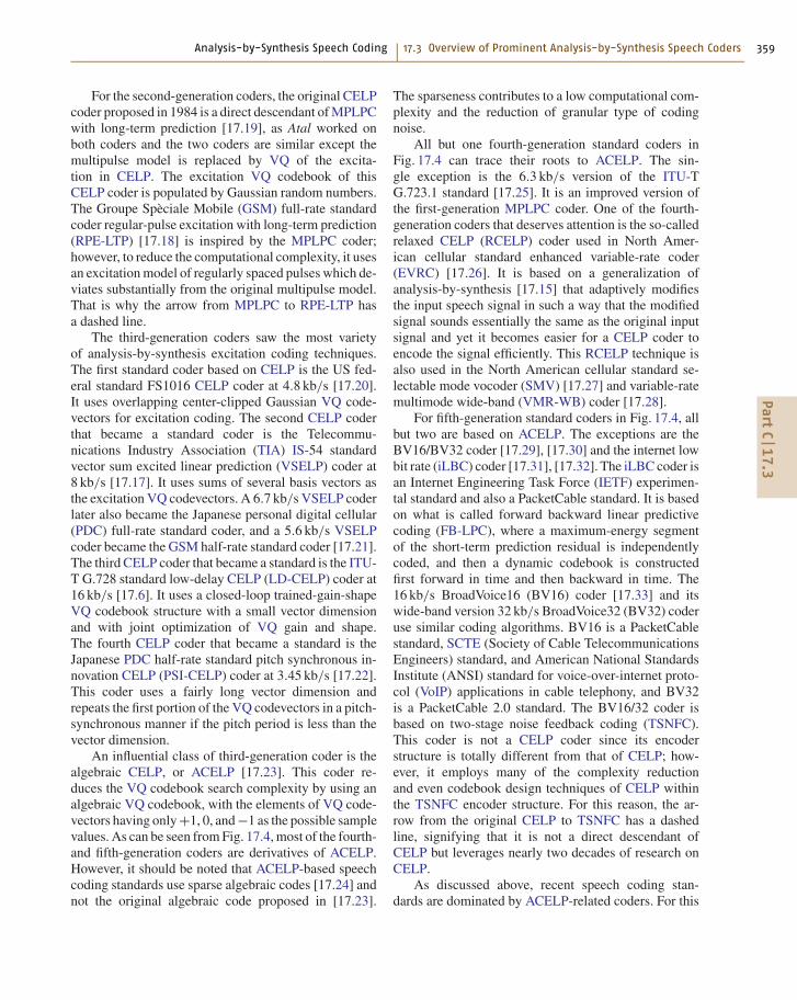
Fig. 17.4 Family tree of prominent analysis-by-synthesis speech waveform coders
Figure 17.4 shows the family tree of these selectedanalysis-by-synthesis speech coders. Each rectangularblock in the tree represents a particular speech coder ora type of speech coders. Within each rectangular block,the first row (sometimes the first two rows) specifies thename of the coding standard, the second row in bold-face letters gives the name of the coding technique, andthe third row provides the year of the first publicationthe authors can find for that coder (either as a technicalpaper or as a standard specification).
The speech coders in Fig. 17.4 are organized in fivedifferent rows, with each row roughly corresponding toa different generation of coders. Each generation rep-resents a group of analysis-by-synthesis speech codersdeveloped within a time period of a few years.
The MPLPC coder [17.2] proposed in 1982 isthe first modern analysis-by-synthesis speech wave-form coder. The original CELP coder [17.3] and theRPE-LTP coder [17.18] in the second row represent
the second-generation analysis-by-synthesis coders de-veloped in the mid 1980s. The five coders in thethird row represent the third-generation analysis-by-synthesis coders developed in the late 1980s and early1990s. The seven coders in the fourth row representthe fourth-generation analysis-by-synthesis coders de-veloped in the mid 1990s. Finally, the seven codersin the fifth row represent the fifth-generation analysis-by-synthesis coders developed from the late 1990s tothe present day. Strictly speaking, the distinctions be-tween the fourth- and fifth-generation coders are notalways clear; however, at least the fifth-generationcoders were developed later than the fourth-generationcoders.
A brief overview of this family tree of analysis-by-synthesis speech coders is given below. The MPLPCcoder proposed in 1982 is at the root of the family tree,since it can be argued that all other coders in Fig. 17.4can trace their roots back to this coder.
PartC
17.3
Analysis-by-Synthesis Speech Coding 17.3 Overview of Prominent Analysis-by-Synthesis Speech Coders 359
For the second-generation coders, the original CELPcoder proposed in 1984 is a direct descendant of MPLPCwith long-term prediction [17.19], as Atal worked onboth coders and the two coders are similar except themultipulse model is replaced by VQ of the excita-tion in CELP. The excitation VQ codebook of thisCELP coder is populated by Gaussian random numbers.The Groupe Spèciale Mobile (GSM) full-rate standardcoder regular-pulse excitation with long-term prediction(RPE-LTP) [17.18] is inspired by the MPLPC coder;however, to reduce the computational complexity, it usesan excitation model of regularly spaced pulses which de-viates substantially from the original multipulse model.That is why the arrow from MPLPC to RPE-LTP hasa dashed line.
The third-generation coders saw the most varietyof analysis-by-synthesis excitation coding techniques.The first standard coder based on CELP is the US fed-eral standard FS1016 CELP coder at 4.8 kb/s [17.20].It uses overlapping center-clipped Gaussian VQ code-vectors for excitation coding. The second CELP coderthat became a standard coder is the Telecommu-nications Industry Association (TIA) IS-54 standardvector sum excited linear prediction (VSELP) coder at8 kb/s [17.17]. It uses sums of several basis vectors asthe excitation VQ codevectors. A 6.7 kb/s VSELP coderlater also became the Japanese personal digital cellular(PDC) full-rate standard coder, and a 5.6 kb/s VSELPcoder became the GSM half-rate standard coder [17.21].The third CELP coder that became a standard is the ITU-T G.728 standard low-delay CELP (LD-CELP) coder at16 kb/s [17.6]. It uses a closed-loop trained-gain-shapeVQ codebook structure with a small vector dimensionand with joint optimization of VQ gain and shape.The fourth CELP coder that became a standard is theJapanese PDC half-rate standard pitch synchronous in-novation CELP (PSI-CELP) coder at 3.45 kb/s [17.22].This coder uses a fairly long vector dimension andrepeats the first portion of the VQ codevectors in a pitch-synchronous manner if the pitch period is less than thevector dimension.
An influential class of third-generation coder is thealgebraic CELP, or ACELP [17.23]. This coder re-duces the VQ codebook search complexity by using analgebraic VQ codebook, with the elements of VQ code-vectors having only +1, 0, and −1 as the possible samplevalues. As can be seen from Fig. 17.4, most of the fourth-and fifth-generation coders are derivatives of ACELP.However, it should be noted that ACELP-based speechcoding standards use sparse algebraic codes [17.24] andnot the original algebraic code proposed in [17.23].
The sparseness contributes to a low computational com-plexity and the reduction of granular type of codingnoise.
All but one fourth-generation standard coders inFig. 17.4 can trace their roots to ACELP. The sin-gle exception is the 6.3 kb/s version of the ITU-TG.723.1 standard [17.25]. It is an improved version ofthe first-generation MPLPC coder. One of the fourth-generation coders that deserves attention is the so-calledrelaxed CELP (RCELP) coder used in North Amer-ican cellular standard enhanced variable-rate coder(EVRC) [17.26]. It is based on a generalization ofanalysis-by-synthesis [17.15] that adaptively modifiesthe input speech signal in such a way that the modifiedsignal sounds essentially the same as the original inputsignal and yet it becomes easier for a CELP coder toencode the signal efficiently. This RCELP technique isalso used in the North American cellular standard se-lectable mode vocoder (SMV) [17.27] and variable-ratemultimode wide-band (VMR-WB) coder [17.28].
For fifth-generation standard coders in Fig. 17.4, allbut two are based on ACELP. The exceptions are theBV16/BV32 coder [17.29], [17.30] and the internet lowbit rate (iLBC) coder [17.31], [17.32]. The iLBC coder isan Internet Engineering Task Force (IETF) experimen-tal standard and also a PacketCable standard. It is basedon what is called forward backward linear predictivecoding (FB-LPC), where a maximum-energy segmentof the short-term prediction residual is independentlycoded, and then a dynamic codebook is constructedfirst forward in time and then backward in time. The16 kb/s BroadVoice16 (BV16) coder [17.33] and itswide-band version 32 kb/s BroadVoice32 (BV32) coderuse similar coding algorithms. BV16 is a PacketCablestandard, SCTE (Society of Cable TelecommunicationsEngineers) standard, and American National StandardsInstitute (ANSI) standard for voice-over-internet proto-col (VoIP) applications in cable telephony, and BV32is a PacketCable 2.0 standard. The BV16/32 coder isbased on two-stage noise feedback coding (TSNFC).This coder is not a CELP coder since its encoderstructure is totally different from that of CELP; how-ever, it employs many of the complexity reductionand even codebook design techniques of CELP withinthe TSNFC encoder structure. For this reason, the ar-row from the original CELP to TSNFC has a dashedline, signifying that it is not a direct descendant ofCELP but leverages nearly two decades of research onCELP.
As discussed above, recent speech coding stan-dards are dominated by ACELP-related coders. For this
PartC
17.3

360 Part C Speech Coding
reason, ACELP and its derivatives will receive more-thorough treatment in this chapter. Nevertheless, thereare still many other interesting kinds of analysis-by-synthesis coders in this family tree. In the sectionsthat follow, the excitation coding methods for the more
distinctive types of coders in this family tree will bedescribed in more detail. Due to the similarity betweenmany different ACELP coders in Fig. 17.4, many of themare lumped together and discussed in the same ACELPsection.
17.4 Multipulse Linear Predictive Coding (MPLPC)The MPLPC coder [17.2] was the first predictive wave-form coder to abandon the sample-by-sample residualquantization procedure and to encode the entire blockof excitation signal as a single entity in an analysis-by-synthesis manner. It achieves this by using an excitationsignal with mostly zero samples and finding the optimallocations and amplitudes for a small number of nonzeropulses such that the resulting synthesized speech signalminimizes a weighted distortion measure in the speechdomain.
Refer to the generic analysis-by-synthesis speechwaveform coder shown in Fig. 17.3. The MPLPC coderdoes not use the signal modifier in Fig. 17.3. The orig-inal MPLPC coder proposed in [17.2] also does notuse the long-term synthesis filter. In fact, this originalMPLPC coder was developed to improve the linear pre-dictive coding (LPC) vocoder [17.34], which does notuse a long-term synthesis filter and have a rigid ex-citation model of either periodic pulse train or whitenoise.
The MPLPC coder does use the short-term synthesisfilter in Fig. 17.3. This short-term synthesis filter is in theform of an all-pole filter given by the following transferfunction
Hs(z) = 1
A(z), (17.1)
where
A(z) = 1− P(z) = 1−M∑
i=1
ai z−i (17.2)
is the short-term prediction error filter, P(z) is theshort-term predictor, ai , i = 1, 2, . . . , M, are the pre-dictor coefficients, and M is the order of the short-termsynthesis filter. The filter order M is typically some-where between 10 and 16 for 8 kHz sampled signals.The predictor coefficients are adaptive and are usuallytransmitted once every 10–20 ms.
In this first MPLPC coder the weighted error mini-mization in Fig. 17.3 is achieved through the use of
a so-called perceptual weighting filter in the form of
W(z) = A(z)
A(z/γ ), 0 < γ < 1 , (17.3)
where
A
(z
γ
)= 1− P
(z
γ
)= 1−
M∑
i=1
aiγi z−i (17.4)
is a modified version of A(z) with the roots of the poly-nomial moved radially toward the origin (the radii ofthe roots are scaled by a factor of γ , which is typically0.8). Since the roots are normally within the unit cir-cle for a stable synthesis filter Hs(z) = 1/A(z), the neteffect is that the magnitude frequency response of thefilter 1/A(z/γ ) is a smoothed version of that of the filter1/A(z).
For MPLPC, the weighted error minimization inFig. 17.3 is achieved by passing the difference betweenthe input speech signal and the synthesized speech sig-nal through the perceptual weighting filter W(z) and thenidentifying which combination of multipulse model pa-rameters gives the minimum mean-squared error of thisperceptually weighted difference signal. The perceptualweighting filter emphasizes the spectral valley regionsand deemphasize the spectral peak regions of the inputspeech spectrum. This has an effect of allowing morecoding noise under the spectral peaks and suppressingcoding noise in the spectral valleys of speech. Thus, theperceptual weighting filter shapes the coding noise spec-trum so that it follows the input speech spectrum to someextent. Due to the noise masking effect of the human au-ditory system, such a spectrally shaped coding noise isperceptually less audible than coding noise with a flatspectrum.
The short-term synthesis filter Hs(z) = 1/A(z) hasa magnitude frequency response corresponding to thespectral envelope of the input signal. Thus, the filterHs(z/γ ) = 1/A(z/γ ) has a magnitude response corre-sponding to a smoothed version of the spectral envelopeof input speech. Subtracting one magnitude response
PartC
17.4

Analysis-by-Synthesis Speech Coding 17.4 Multipulse Linear Predictive Coding (MPLPC) 361
from another in the logarithmic domain is equivalent todividing in the linear domain. Hence, the filter
1
W(z)= A(z/γ )
A(z)= Hs(z)
Hs(z/γ )(17.5)
will have a magnitude response somewhat similar tothe spectral envelope of the input speech but with a re-duced spectral slope. Since this filter is the inverse ofthe perceptual weighting filter W(z), given how theweighted error minimization works as described above,the magnitude response of this filter 1/W(z) is the spec-tral envelope of the coding noise that the MPLPC coderwill achieve. For an example of what the magnituderesponses of Hs(z) and W(z) look like, see [17.2].
The first MPLPC coder in [17.2] encoded the exci-tation signal block-by-block in an analysis-by-synthesismanner using a block size of 5 ms, or 40 samples at 8 kHzsampling. Most of the 40 samples are zeroes. Only about10% of the 40 excitation samples (four samples) havenonzero amplitudes. These nonzero samples are calledpulses because they look like pulses in the graphicalrepresentation of such a digital excitation signal. Sincethere are usually multiple of such nonzero samples inthe block of excitation signal to be encoded, the result-ing excitation model is called the multipulse model, andthe resulting linear predictive coding scheme is calledmultipulse linear predictive coding (MPLPC).
Let m be the number of pulses in each block of ex-citation signal. Each pulse is completely specified by itsamplitude and its location within the block. Therefore,the multipulse excitation model has 2m model parame-ters that need to be determined. Jointly optimizing these2m model parameters would cost too high computa-tional complexity. A suboptimal sequential optimizationapproach is proposed in [17.2].
In the sequential optimization approach, the m pulsesare determined one at a time. For a given pulse location,the corresponding optimal amplitude can be obtainedthrough a closed-form solution [17.2]. Before determin-ing the location and amplitude of the first pulse, withthe excitation signal set to zero, the output of the short-term synthesis filter during the current block (due to thenonzero filter memory left over at the end of the lastblock) is subtracted from the input speech. The result isthe target signal for the search of the first pulse. Eachof the 40 possible pulse locations is tried. With closed-loop optimal amplitude solved for each pulse location,the pulse is passed through the short-term synthesis filter.The filter output signal is subtracted from the target sig-nal and the resulting difference signal is passed throughthe perceptual weighting filter. The mean-squared error
(MSE) of the weighted signal is calculated. This processis repeated until the best pulse location and amplitudethat gives the lowest weighted error is identified. Next,the short-term synthesis filter output signal due to thisfirst pulse is subtracted from the target signal to forma new target signal for the search of the second pulse.This process is repeated until the pulse locations of allm pulses are determined. Then, given the m pulse loca-tions, the m pulse amplitudes can be jointly optimizedin a single step [17.2].
Using this approach, it is reported in [17.2] that onlyminimal audio quality improvement are achieved afterabout eight pulses have been placed in a 10 ms interval.It is also reported [17.2] that the resulting output speechquality sounded natural and perceptually close to theinput speech, without the common unnatural and buzzycharacteristics of the LPC vocoder output speech.
Strictly speaking, since each pulse in the multipulsemodel is scaled by a different amplitude, the decom-position of the excitation generator into the excitationshape generator and the excitation gain in Fig. 17.3 isnot a good description. This problem can be avoided ifthe excitation gain in Fig. 17.3 is understood to have thepossibility of taking the form of a gain vector (with di-mension m), where each element of the gain vector isindividually used to scale one of the m pulses.
Further improvements to this initial MPLPC coderwas proposed in [17.19]. The most notable is the ad-dition of a pitch predictor, or equivalently, the additionof the long-term synthesis filter in Fig. 17.3. Due to thequasiperiodicity in voiced speech such as vowels, it isfound that the multipulse excitation signal shows sig-nificant correlation from one pitch period to the next.This correlation can be exploited by using a pitch pre-dictor (also called long-term predictor). Let the pitchperiod be T samples, and let β be the long-term predictorcoefficient. Then, with
Hl(z) = 1
1−βz−T(17.6)
chosen as the transfer function of the long-term synthesisfilter in Fig. 17.3, each pulse at the output of the long-term synthesis filter will be scaled by β and then be addedto the excitation signal T samples later. This has theeffect of creating a periodic pulse pattern at a period ofT samples. After adding this long-term synthesis filter,fewer pulses are needed to produce the same level ofspeech quality.
Another improvement proposed in [17.19] is relatedto pulse amplitude optimization. Rather than waitinguntil all pulse locations are determined and then jointly
PartC
17.4
362 Part C Speech Coding
optimize all the pulse amplitudes, the proposed proce-dure performs reoptimization of amplitudes along theway. In other words, during the sequential search forpulse locations, after the j-th pulse location is deter-mined (1 ≤ j ≤ m), all pulse amplitudes from the firstpulse to the j-th pulse are reoptimized jointly beforecontinuing to search for the ( j +1)-th pulse location. Itis reported [17.19] that this approach improved coderoutput signal-to-noise ratio (SNR) by 2–10 dB, with anaverage of slightly over 3 dB.
There are many other improvements and variationsproposed in the literature for the MPLPC coder. Dueto the space limitation, they have to be omitted in thediscussion here.
The multipulse excitation model is used in the ITU-T Recommendation G.723.1 speech coder. G.723.1 hastwo bit-rates. The lower-bit-rate 5.3 kb/s version isbased on ACELP, while the higher-bit-rate 6.3 kb/sversion is based on MPLPC with long-term prediction.
This 6.3 kb/s version of G.723.1 uses a frame size of30 ms, which is equally divided into four subframes of7.5 ms (60 samples) each. Multipulse excitation search isperformed on each of the four subframes. The multipulseexcitation model uses six pulses for even subframes andfive pulses for odd subframes. The pulse location is re-
stricted to be either all even or all odd, as indicatedby a grid bit. Furthermore, all pulses are constrainedto have the same magnitude, although different pulsescan have different signs. The shared magnitude is firstestimated and quantized. Then, four quantized magni-tude values around the estimated magnitude are allowedin the analysis-by-synthesis multipulse search. For eachof these four possible quantized magnitude values, thepulse locations and signs are sequentially optimized onepulse at a time. This procedure is repeated for both theeven and odd pulse position grids. Finally, the best com-bination of all these parameters (quantized magnitude,pulse locations and signs, and even or odd grid) that givesthe minimum weighted error of the synthesized speechis selected as the final multipulse excitation parametersto be transmitted to the G.723.1 decoder.
As can be seen, this G.723.1 multipulse coder has de-viated substantially from the original MPLPC proposedin [17.2] and [17.19]. In fact, with all the constraints puton the G.723.1 multipulse model (due to the low-bit-rate limitation), the G.723.1 multipulse excitation signalstarts to resemble to some extent the excitation signalof ACELP coders. However, such constraints aside, thespirit of the original multipulse excitation model can stillbe seen in this 6.3 kb/s G.723.1 multipulse coder.
17.5 Regular-Pulse Excitation with Long-Term Prediction (RPE-LTP)The regular-pulse excitation (RPE) coder [17.35] can beregarded as a special low-complexity realization of thefundamental analysis-by-synthesis concept proposed inthe original multipulse LPC coder [17.2]. A special ver-sion of it, the regular-pulse excitation with long-termprediction (RPE-LTP) coder at 13 kb/s [17.18], was se-lected as the first GSM standard coder for Europeandigital cellular service.
The RPE excitation model consists of J possible se-quences of regularly spaced pulses, each with the pulseslocated at a different phase. The typical value of J is3 or 4. As an example, for the k-th sequence of pulses,the nonzero excitation samples (the pulses) are locatedat the positions of k, k + J, k +2J, k +3J, . . . , and thesample values at other locations are zero. The task of ex-citation coding is to find the amplitude values for eachof the pulses in each of the J sequences of regularlyspaced pulses, and then find the sequence of pulses thatminimizes a weighted error measure.
Similar to the original MPLPC coder proposedin [17.2], the initial RPE coder [17.35] also did not
use a long-term predictor. On a conceptual level, the en-coder structure of the initial RPE coder is equivalentto the structure in Fig. 17.3 without the long-term syn-thesis filter and the signal modifier. However, in actualimplementation, the LPC inverse filter A(z), which isthe numerator portion of the perceptual weighting filterW(z) = A(z)/A(z/γ ), is moved beyond the adder to theleft and above. The one to the left of the adder cancels outthe short-term synthesis filter, while the one above theadder stays there and filters the input speech to producethe short-term prediction residual. The remaining de-nominator portion of the weighting filter, or 1/A(z/γ ),stays below the adder for weighted error minimization.
In [17.35], the procedure for the RPE analysis-by-synthesis excitation search is given. It basically amountsto solving J sets of linear equations to find the optimalamplitude for each pulse of the J possible regular pulsesequences. The weighted distortion measure for each ofthe J pulse sequences are calculated and the sequencethat minimizes the weighted distortion is selected as thefinal excitation sequence.
PartC
17.5
Analysis-by-Synthesis Speech Coding 17.6 The Original Code Excited Linear Prediction (CELP) Coder 363
In the GSM full-rate (GSM-FR) standard RPE-LTPcoder, a single-tap long-term predictor (LTP) is addedto the initial RPE coder, so GSM-FR corresponds to thecoder structure in Fig. 17.3 with the long-term synthesisfilter enabled. The GSM-FR coder uses three possiblesequences of regularly space pulses, that is, J = 3. Ithas a frame size of 20 ms and a subframe size of 5 ms.Therefore, for every 5 ms subframe of 40 samples, thereare 3 possible sequences of regularly spaced pulses. Eachsequence contains only 13 or 14 nonzero pulses, with theremaining samples having zero amplitudes. The selected
sequence is identified by 2 bits, and the correspondingpulse amplitudes are encoded with a 3-bit block-adaptivePCM quantizer. The block maximum for each subframeis encoded with 6 bits. The pitch period and the pitch tapare derived once a subframe and quantized to 7 bits and2 bits, respectively.
This GSM-FR RPE-LTP coder is the speech coderfor the first-generation GSM digital cellular telephones.It became the first analysis-by-synthesis coder thatwas standardized and widely deployed across manycountries.
17.6 The Original Code Excited Linear Prediction (CELP) CoderBy using an analysis-by-synthesis procedure, the mul-tipulse excitation model in the MPLPC coder [17.2]opened the door for significantly more efficient ex-citation coding than was possible with earlier speechwaveform coders. However, even with this multipulsemodel, there is still a limit on how low the excitationencoding bit-rate can go. For example, with the same40-sample excitation block size and four pulses as inthe original MPLPC, suppose it is desirable to encodethe excitation signal at a bit rate of 1/4 bits/sample, thisgives a mere 10 bits to represent the four pulse locationsand four pulse amplitudes. It is virtually impossible touse 10 bits to quantize such eight parameters with suffi-cient accuracy. This problem led Atal and Schroeder touse a 10 bit vector quantization (VQ) codebook to quant-ize the excitation signal [17.3], leading to what is knowntoday as code-excited linear prediction, or CELP [17.4].
To use 10-bit VQ to quantize 40 samples of the ex-citation signal, Atal and Schroeder constructed a VQcodebook containing 210 = 1024 codevectors, each ofwhich is a 40-dimensional vector containing 40 whiteGaussian random numbers with unit variance. Besideconceding that it is generally difficult to design an op-timum deterministic codebook (with a total of 40 960samples in it), in [17.4] Schroeder and Atal actually gavea justification for using the Gaussian random numbers.The justification is that the probability density functionof the prediction residual signal after both short- andlong-term prediction is nearly Gaussian.
The encoder structure of this initial CELP coder fitsthe structure shown in Fig. 17.3 exactly. Again, the signalmodifier in Fig. 17.3 is not used in this CELP coder. Theexcitation shape generator is basically a table look-upof the 10-bit, 40-dimensional excitation VQ codebookdescribed earlier. The excitation gain scales the unit-
variance Gaussian codevectors to the proper gain levelthat matches the root mean square (RMS) value of theprediction residual signal after both short-term and long-term prediction. It is updated once every 5 ms togetherwith the excitation codevector.
The synthesis filter of CELP contains both the long-term synthesis filter and the short-term synthesis filter.The short-term synthesis filter has the same form asgiven in (17.1), while the long-term synthesis filter usesa 3-tap pitch predictor rather than the single-tap pitchpredictor given in (17.6). The weighted error mini-mization of CELP is also achieved with a perceptualweighting filter in exactly the same way as in MPLPC,described earlier in Sect. 17.4. The perceptual weight-ing filter W(z) also has exactly the same form as definedin (17.3).
Atal and Schroeder reported [17.3, 4] that whenthe 40-sample excitation vector is quantized to0.25 bit/sample in an analysis-by-synthesis manner us-ing a 10-bit Gaussian VQ codebook, with all otherspeech synthesis model parameters (excitation gain andparameters for the long- and short-term synthesis filters)left at their open-loop-derived optimal values, the result-ing synthesized speech sounded very close to the originalinput speech. Only small differences were noticeableeven in close pairwise comparisons over headphones.
Achieving such a high level of output speech qualitywith such a low bit rate of merely 0.25 bit/sample forthe excitation signal was considered a stunning break-through in 1984–1985. Almost immediately, a largenumber of speech coding researchers jumped in andengaged in the research of the CELP coding tech-nique. In the subsequent years that followed, hundredsof CELP-related technical papers have been publishedand numerous advancements in CELP coding have been
PartC
17.6

364 Part C Speech Coding
made. As shown in the family tree of Fig. 17.4, thisanalysis-by-synthesis CELP coding idea eventually ledto more than a dozen of modern low-bit-rate speechcoding standards, and CELP-related coders dominatealmost all speech coding standards established since thelate 1980s.
The two initial CELP papers [17.3, 4] were moreproof of concept papers than actual coder design papers.Not only were all model parameters except the exci-tation signal were left unquantized, but a major issuewas the very high computational complexity requiredby the analysis-by-synthesis excitation VQ codebooksearch.
Actually, it is fairly easy to estimate the com-plexity of such a codebook search. Refer to Fig. 17.3.Given that the short-term filter order they used wasM = 16, each of the 1024 excitation codevectors hasto be scaled by the excitation gain (one multiply persample), filtered by the long-term synthesis filter (threemultiply-adds per sample), filtered by the short-termsynthesis filter (16 multiply–adds per sample), sub-tracted from the input speech (one subtract per sample),filtered by the perceptual weighting filter (2 × 16 = 32multiply–adds per sample), squared (one multiply persample), and then added (one add per sample) to getthe weighted distortion value of that codevector. There-fore, at a sampling rate of 8000 Hz, the total complexityfor searching through all 1024 excitation codevec-tors to identify the one that minimizes the weighteddistortion measure would take at least 8000 × 1024 ×(1+3+16+1+32+1+1) = 450 560 000 operationsper second, or 450.6 MFLOPS (million floating-pointoperations per second). Even the fastest supercom-puter at that time could not perform computations thatfast. No wonder Atal and Schroeder reported [17.3,4] that their initial CELP simulation took 125 s
���� ���
� ��$��
)���� ����(���� ���
)���� ����<�
��������
���(�����
�!������"�����
��������
�!������"�����
����������
!�������������
�������� �@��(���("�����
2 )������� ����
���
�
#� ���
��
Fig. 17.5 Encoder structure of the original CELP coder
of central processor unit (CPU) time on the then-supercomputer Cray-1 to process just one second ofspeech.
However, even Atal and Schroeder pointed out [17.4]at that time that
a code book with sufficient structure amenable tofast search algorithms could lead to real-time im-plementation of code-excited coders.
This turned out to be true. In subsequent years many spe-cially structured excitation VQ codebooks that allowedfast codebook search were proposed – the excitationcodebooks of ACELP, VSELP, and FS1016 CELP areall good examples.
However, even without such specially structured ex-citation codebooks, by just re-arranging the encoderstructure in Fig. 17.3 and performing the CELP exci-tation codebook search in a mathematically equivalentway, the computational complexity can be reduced byalmost an order of magnitude. This efficient encoderstructure and excitation codebook search procedure isexplained below. It forms the basis of essentially allpractical CELP-based coders today.
Consider the encoder structure shown in Fig. 17.5.This structure is basically the same as the genericanalysis-by-synthesis coder structure shown in Fig. 17.3,except that specific filter structure and transfer functionsare given. For convenience of later discussion of theso-called adaptive codebook, the long-term synthesisfilter is reverted from a three-tap filter back to a single-tap filter as used in the improved MPLPC [17.19]. Theshort-term synthesis filter is 1/A(z). The weighted er-ror minimization is explicitly separated into a perceptualweighting filter as defined in (17.3) followed by MSEminimization. Even with the three-tap pitch filter re-placed by a single-tap one, the complexity is still 8000 ×1024 × (1+1+16+1+32+1+1) = 434.2 MFLOPS.
As suggested in [17.19], the perceptual weightingfilter can be moved before the adder in Fig. 17.5 sothat the input speech and the synthesized speech areeach individually weighted before the difference of thetwo weighted signals are calculated. The cascade of theshort-term synthesis filter and the perceptual weightingfilter gives a weighted short-term synthesis filter in theform of
H(z) = W(z)
A(z)= 1
A(z)
A(z)
A(z/γ )= 1
A(z/γ ). (17.7)
This is shown in Fig. 17.6. Even this step alone cancut the computational complexity by almost a factor ofthree. There is more that can be saved. However, before
PartC
17.6
Analysis-by-Synthesis Speech Coding 17.6 The Original Code Excited Linear Prediction (CELP) Coder 365
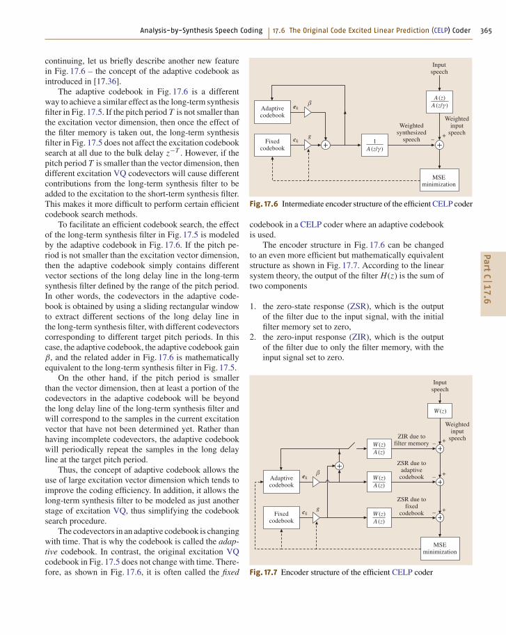
continuing, let us briefly describe another new featurein Fig. 17.6 – the concept of the adaptive codebook asintroduced in [17.36].
The adaptive codebook in Fig. 17.6 is a differentway to achieve a similar effect as the long-term synthesisfilter in Fig. 17.5. If the pitch period T is not smaller thanthe excitation vector dimension, then once the effect ofthe filter memory is taken out, the long-term synthesisfilter in Fig. 17.5 does not affect the excitation codebooksearch at all due to the bulk delay z−T . However, if thepitch period T is smaller than the vector dimension, thendifferent excitation VQ codevectors will cause differentcontributions from the long-term synthesis filter to beadded to the excitation to the short-term synthesis filter.This makes it more difficult to perform certain efficientcodebook search methods.
To facilitate an efficient codebook search, the effectof the long-term synthesis filter in Fig. 17.5 is modeledby the adaptive codebook in Fig. 17.6. If the pitch pe-riod is not smaller than the excitation vector dimension,then the adaptive codebook simply contains differentvector sections of the long delay line in the long-termsynthesis filter defined by the range of the pitch period.In other words, the codevectors in the adaptive code-book is obtained by using a sliding rectangular windowto extract different sections of the long delay line inthe long-term synthesis filter, with different codevectorscorresponding to different target pitch periods. In thiscase, the adaptive codebook, the adaptive codebook gainβ, and the related adder in Fig. 17.6 is mathematicallyequivalent to the long-term synthesis filter in Fig. 17.5.
On the other hand, if the pitch period is smallerthan the vector dimension, then at least a portion of thecodevectors in the adaptive codebook will be beyondthe long delay line of the long-term synthesis filter andwill correspond to the samples in the current excitationvector that have not been determined yet. Rather thanhaving incomplete codevectors, the adaptive codebookwill periodically repeat the samples in the long delayline at the target pitch period.
Thus, the concept of adaptive codebook allows theuse of large excitation vector dimension which tends toimprove the coding efficiency. In addition, it allows thelong-term synthesis filter to be modeled as just anotherstage of excitation VQ, thus simplifying the codebooksearch procedure.
The codevectors in an adaptive codebook is changingwith time. That is why the codebook is called the adap-tive codebook. In contrast, the original excitation VQcodebook in Fig. 17.5 does not change with time. There-fore, as shown in Fig. 17.6, it is often called the fixed
3������������
����������
*��(����!�������������
2 )������� ����
���
�
#� ��$��
��
� ���� ��$��
*��(�������������
>� ���+���������
��
Fig. 17.6 Intermediate encoder structure of the efficient CELP coder
codebook in a CELP coder where an adaptive codebookis used.
The encoder structure in Fig. 17.6 can be changedto an even more efficient but mathematically equivalentstructure as shown in Fig. 17.7. According to the linearsystem theory, the output of the filter H(z) is the sum oftwo components
1. the zero-state response (ZSR), which is the outputof the filter due to the input signal, with the initialfilter memory set to zero,
2. the zero-input response (ZIR), which is the outputof the filter due to only the filter memory, with theinput signal set to zero.
3������������
A��������"�����������!
2 )������� ����
���
�
� ���
>� ���+���������
��
� ���� ���
� �
*��(�������������
A ������� � ���+���������� ���
� ���� �
A �������"����
��������� ���� ���
� �
����������
Fig. 17.7 Encoder structure of the efficient CELP coder
PartC
17.6
366 Part C Speech Coding
Note that the ZIR does not depend on which excitationVQ codevector is used. Thus, by decomposing the outputof the weighted short-term synthesis filter H(z) into ZIRand ZSR, the ZIR component can first be subtracted outof the weighted speech signal, and the resulting signalbecomes the target signal for the codebook search basedon the ZSR component. In fact, this idea was alreadysuggested by Atal and Remde in their original MPLPCpaper [17.2], even though they did not use the terms ofZIR and ZSR.
In some later CELP coders, the perceptual weight-ing filter took a form different from what was specifiedin (17.3). Therefore, to keep Fig. 17.7 general, theweighted short-term synthesis filter is represented asH(z) = W(z)/A(z).
In Fig. 17.6, the excitation signal to the short-termsynthesis filter has two components: the scaled adap-tive codebook vector βek and the scaled fixed codebookvector gck. Therefore, the weighted synthesized speechsignal in Fig. 17.6 can be decomposed into three com-ponents: the ZIR signal due to the memory of thefilter W(z)/A(z), the ZSR signal due to the adaptivecodebook, and the ZSR signal due to the fixed codebook.
In the efficient CELP excitation codebook searchmethod based on Fig. 17.7, the input speech vector isfirst passed through the perceptual weighting filter W(z)to get the weighted input speech vector. Then, the ZIRvector due to the filter memory is calculated by settingthe initial memory of the weighted short-term synthe-sis filter to the filter memory at the last sample of thelast input speech vector and letting the filter ring with-out any input excitation signal (the switch in Fig. 17.7 isopen). This ZIR vector is subtracted from the weightedinput speech vector to get the target vector for the nextstage. Next, the adaptive codebook index (the pitch pe-riod) and the adaptive codebook gain (the pitch gain) areusually determined in an analysis-by-synthesis mannerto minimize the MSE between the target vector obtainedabove and the ZSR vector due to the adaptive codebook.The ZSR vector corresponding to the best combinationof the pitch period and the pitch gain is then subtractedfrom the target vector to get the next target vector for theZSR vector due to the fixed codebook. Finally, the fixedcodebook index and the fixed codebook gain are deter-mined in an analysis-by-synthesis manner to minimizethe MSE between this next target vector and the ZSRvector due to the fixed codebook. After such a codebooksearch, the selected codebook vectors and gains are usedto calculate the sum of the two excitation componentsβek + gck, and the resulting final excitation vector isused to update the adaptive codebook and the memory
of the weighted short-term synthesis filter (the switchis closed). Then, this procedure is repeated for the nextinput speech vector.
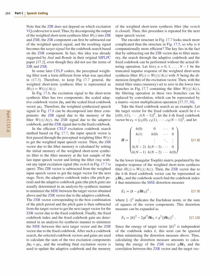
The encoder structure in Fig. 17.7 looks much morecomplicated than the structure in Fig. 17.5, so why is itcomputationally more efficient? The key lies in the factthat by subtracting out the ZIR vector due to filter mem-ory, the search through the adaptive codebook and thefixed codebook can be performed without the actual fil-tering operation. Let h(n), n = 0, 1, . . . , N −1 be thetruncated impulse response of the weighted short-termsynthesis filter H(z) = W(z)/A(z) with N being the di-mension (length) of the excitation vector. Then, with theinitial filter states (memory) set to zero in the lower twobranches in Fig. 17.7 containing the filter W(z)/A(z),the filtering operation in these two branches can bereplaced by convolution, which can be represented bya matrix–vector multiplication operation [17.37, 38].
Take the fixed codebook search as an example. Letthe target vector for the fixed codebook search be t =[t(0), t(1), · · · , t(N −1)]T, let the k-th fixed codebookvector be ck = [ck(0), ck(1), · · · , ck(N −1)]T, and let
H =
⎛⎜⎜⎜⎜⎜⎜⎝
h(0) 0 · · · 0
h(1) h(0) · · · 0...
.... . .
...
h(N −2) h(N −3) · · · 0
h(N −1) h(N −2) · · · h(0)
⎞⎟⎟⎟⎟⎟⎟⎠
(17.8)
be the lower triangular Toeplitz matrix populated by theimpulse response of the weighted short-term synthesisfilter H(z) = W(z)/A(z). Then, the ZSR vector due tothe k-th fixed codebook vector can be represented asgHck, and the codebook search find the codebook indexk that minimizes the MSE distortion measure
Ek = ‖t − gHck‖2 , (17.9)
where ‖ · ‖2 indicates the Euclidean norm, or the sumof squares of the vector components. This distortionmeasure can be expanded as
Ek = ‖t‖2 −2gtT Hck + g2‖Hck‖2 . (17.10)
Since the energy of target vector ‖t‖2 is independentof the codebook index k, this term can be ignoredwhen minimizing the distortion measure above. Thus,calculating the distortion measure amounts to calcu-lating the energy of the ZSR vector gHck and thecorrelation between this ZSR vector and the target vec-
PartC
17.6
Analysis-by-Synthesis Speech Coding 17.7 US Federal Standard FS1016 CELP 367
tor t. The adaptive codebook search can be formulatedin the same way using the same kind of distortionmeasure.
Many efficient codebook search procedures havebeen proposed based on the distortion measure in(17.10). In addition, many special fixed codebook struc-
tures that allow efficient codebook search have beenproposed in the literature. Together these techniques en-abled the computational complexity to be reduced fromthe 430+ MFLOPS of the original CELP to 10 MFLOPSand below for many of the practical CELP coders de-ployed today.
17.7 US Federal Standard FS1016 CELP
The US Federal Standard FS1016 coder [17.20] is thefirst CELP coder ever standardized. It was developedby the US Department of Defense and is quite simi-lar to the stochastically excited linear prediction (SELP)coder proposed in [17.36]. This coder uses a frame sizeof 30 ms. Each frame is divided into four subframes of7.5 ms each (60 samples at 8 kHz sampling). The adap-tive codebook approach described in [17.36] is used todetermine the pitch period (also called the pitch lag)and the pitch gain once every subframe. (In this case,there is one excitation vector in each subframe.) Forodd-numbered subframes, the pitch lag takes an inte-ger value between 20 and 147 and thus can be encodedinto 7 bits. For even-numbered subframes, the pitch lagis constrained to be within 32 samples relative to thepitch lag of the previous subframe. The pitch gain iscoded using a five-bit nonuniform scalar quantizer. Forthe fixed codebook, the FS1016 standard uses a spe-cially structured codebook where adjacent codevectorsare essentially shifted version of each other and differby only two samples at the end. This kind of shiftedfixed codebook was first proposed in [17.39]. How-ever, it was also independently studied in [17.36] usingan improved distortion measure, and the optimal trade-off of the two-sample shift was evaluated and proposedin [17.36].
This shifted fixed codebook introduces a certain con-straint and structure into the codebook and allows anefficient codebook search. This is because when adja-cent fixed codebook vectors are shifted version of eachother, a large part of the ZSR computations in the matrix-vector multiplication Hck can be reused when goingfrom one codevector to the next. Therefore, once theZSR is calculated for the first codevector, the ZSR ofthe remaining codevectors can be obtained recursivelywith low complexity. This same principle also appliesto the adaptive codebook search for those pitch lagsthat are not smaller than the excitation vector dimension(subframe size), since the corresponding adjacent adap-tive codevectors are simply 1-sample shifted versions ofeach other.
To illustrate how a shifted codebook can re-duce the codebook search complexity, first considera fixed codebook with a one-sample shift betweenadjacent codevectors. In [17.39], a 1024-sample cir-cular buffer ν(n), n = 0, 1, . . . , 1023 is used to storethe 1024 codevectors of a 10-bit fixed codebook with1-sample shift. The j-th codevector is defined to beck(n) = ν(k +n), 0 ≤ n ≤ N −1, 0 ≤ k ≤ 1023, whereν(k +1024) = ν(k) since ν(n) is in a circular buffer. LetHck = rk = [rk(0), rk(1), . . . , rk(N −1)]T. Then, due tothe lower triangular Toeplitz structure of the H matrix,it is shown in [17.39] that rk+1(n) can be computedrecursively from rk(n) as follows.
rk+1(n −1) = rk(n)−ν(k)h(n) , 1 ≤ n ≤ N −1 ,
rk+1(N −1) =N−1∑
n=0
ν(k +1+n)h(N −1−n) .
This recursion is best understood with a graphical in-terpretation of the matrix-vector multiplication Hck. Insuch a multiplication, the column vector ck is turnedsideways by 90◦ counterclockwise, then each of itselements is sample-by-sample multiplied with each el-ement of the corresponding column of the matrix H.Next, all the product terms along each row of the ma-trix is summed. The resulting column vector is rk. In therecursion above proposed in [17.39], when going fromck to ck+1, the top element of ck is removed, the re-maining N −1 element is shifted up by one sample, anda new element is added at the bottom. Due to the lowertriangular Toeplitz structure of the matrix H, most ofthe product terms and the partial sums needed for rk+1are already calculated for rk and thus can be reused.However, the contribution to rk(n) due to the removedtop element of ck is already added to the element ofrk. That is why in the first equation of the recursionabove, the product term contribution due to the top ele-ment of rk needs to be subtracted out again. None of theproduct terms in the second equation of the recursionabove involving rk+1(N −1) has been calculated whencalculating rk, so the entire summation in this second
PartC
17.7
368 Part C Speech Coding
equation needs to be calculated. This recursion abovecosts (N −1)+ N = 2N −1 multiply–add operations foreach new rk+1 vector.
In fact, there is an even more-efficient recursion thatrequires only N −1 multiply–add operations for eachnew rk vector. The trick is to reverse the order of the rkvectors in the recursion. Using the graphical interpreta-tion of the matrix-vector multiplication Hck explainedabove, one can see that if the recursion now starts atr1023 and going backward toward r0, then each timewhen going from ck+1 to ck, the bottom (last) elementof ck+1 is removed, the remaining elements are shifteddown by one sample, and a new element is added at thetop. However, for the first N −1 element of ck+1 thatare being shifted down, their partial sum contributionsto rk are exactly the first N −1 elements of rk+1. Af-ter these first N −1 elements of ck+1 have been shifteddown and a new element added at the top to get ck , theirpartial sum contributions to rk correspond to the productterms in the second through the N-th columns of the ma-trix H. Thus, only the product terms in the first columnneed to be added to the partial sums already calculatedand stored in the first N −1 elements of rk+1. Thus, therecursion can be described as
rk(n) = rk+1(n −1)+ν(k)h(n) , 1 ≤ n ≤ N −1 ,
rk(0) = ν(k)h(0) = ν(k) .
The last equality above holds because h(0) = 1. There-fore, this recursion performed in the reverse orderrequires only N −1 multiply-add operations for eachnew rk vector. As mentioned above, this recursion canbe used for the adaptive codebook search for those pitchlags not smaller than the subframe size.
The effect of shifting more than one sample betweenadjacent codevectors in the fixed codebook has beenstudied and reported in [17.36]. As the amount of shiftbetween adjacent fixed codebook vectors increases, thecoder performance increases, but the codebook searchcomplexity also increases. It was found in [17.36] thatfor a large codebook (with 128 or more codevectors),a two-sample shift gives the same performance as a fullyindependent codebook. For this reason, the FS1016coder uses such a fixed codebook with a two-sampleshift between adjacent codevectors.
The same basic idea in the more efficient recursionabove can easily be extended to the fixed codebook witha two-sample shift. In this case, each time when goingfrom ck+1 to ck , the bottom two elements of ck+1 areremoved, the remaining elements are shifted down bytwo samples, and two new elements are added at thetop. For the first N −2 element of ck+1 that are beingshifted down, their partial sum contributions to rk areexactly the first N −2 elements of rk+1. These partialsum contributions to rk correspond to the product termsin the third through the N-th columns of the matrix H.Thus, only the product terms in the first two columnsneed to be added to the partial sums already calculatedand stored in the first N −2 elements of rk+1. Thus,this recursion takes only (N −1)+ (N −2) = 2N −3multiply–add operations to calculate each new rk.
In the case of the FS1016 coder, the elements of thefixed codebook are obtained by using a sequence of zero-mean, unit-variance, white Gaussian random numbersthat are center-clipped at 1.2, which results in roughly75% of the samples being zero. Thus, the fixed codebookis not only shifted, but also 75% sparse.
A sparse fixed codebook is said to produce slightlyimproved perceptual quality of the CELP outputspeech [17.36,38]. Furthermore, a sparse fixed codebookalso reduces the codebook search complexity [17.38].The reason is quite simple. Consider the graphical in-terpretation of the matrix–vector multiplication Hckagain. When 75% to 90% of the elements in ck arezero, the product terms in the corresponding columnsof the matrix H do not need to be calculated, and thusthe corresponding calculations can be saved. Accordingto [17.20], the shifted sparse fixed codebook structurereduces the computation by a factor of 20.
In the FS1016 coder, the fixed codebook gain isquantized to 5 bits using a non-uniform scalar quantizer.An interoperable coder may use only a subset of thefixed codebook to reduce the computational complexity.The FS1016 coder also uses unequal forward error cor-rection to protect perceptually most sensitive bits, and ituses extensive parameter smoothers to reduce the qual-ity degrading effects of bit errors. At the time it wasstandardized, the output speech quality of the FS1016coder was considered one of the best at around 4.8 kb/s.
17.8 Vector Sum Excited Linear Prediction (VSELP)Vector sum excited linear prediction (VSELP) [17.17,40] is another class of CELP coder that usesa specially structured fixed codebook to reduce
the codebook search complexity. VSELP is thesecond type of CELP coder that was standard-ized.
PartC
17.8
Analysis-by-Synthesis Speech Coding 17.8 Vector Sum Excited Linear Prediction (VSELP) 369
Each codevector in the fixed codebook of VSELPis constructed as a weighted sum of M indepen-dent basis vectors, with the weights taking only twopossible values: +1 or −1. Thus, an M-bit fixedcodebook uses exactly M basis vectors. Let vm =[vm(0), vm(1), . . . , vm(N −1)]T , m = 1, 2, . . . , M bethe M basis vectors. Then, the 2M codevectors in anM-bit VSELP fixed codebook is constructed as
ck =M∑
m=1
θkmvm (17.11)
for k = 0, 1, . . . , 2M , where θkm = +1 if bit m of thek-th codeword is 1, and θkm = −1 if bit m of the k-thcodeword is 0.
An 8 kb/s VSELP coder [17.17] was selected as theTIA interim standard IS-54 for North American digi-tal cellular telephone applications, although this IS-54standard was later rescinded. A 6.7 kb/s VSELP coderwas selected as the Japanese digital cellular PDC full-rate (PDC-FR) standard coder, and a 5.6 kb/s VSELPcoder [17.21] also became the GSM half-rate (GSM-HR) standard coder.
In the IS-54 VSELP coder, there are two fixed code-books sequentially searched, similar to a multistage VQconfiguration. In the PDC-FR VSELP coder, only onefixed codebook is used. In the GSM-HR VSELP coder,there are two fixed codebooks, but how many fixedcodebooks are used depends on the voicing mode. Forexample, for a voiced mode the adaptive codebook andone of the fixed codebooks is used, but for an unvoicedmode the adaptive codebook is not used and two fixedcodebooks are used.
In the IS-54 VSELP coder, the adaptive codebookand the two fixed codebooks are treated like three suc-cessive stages of quantization. The codebook gains areleft floating when searching for the codebook vectorsof these three stages. The mathematics of the efficientcodebook search is somewhat involved. Due to the spacelimitation, only the basic concepts will be described be-low. Interested readers are referred to [17.17] for moremathematical details.
The adaptive codebook is first searched using themethod described in Sect. 17.7. Next, when searchingeach of the two fixed codebooks, each of the M basisvectors are first filtered through the weighted short-termsynthesis filter with zero initial memory to get the ZSRvector of that basis vector. Then, each of such ZSRvectors are orthogonalized with respect to each otherand with respect to the ZSR vector due to the selectedadaptive codebook vector. The ZSR vector due to each
of the 2M fixed codebook vectors can then be expressedas a linear combination of the M orthogonalized ZSRvectors due to the M basis vectors.
The search procedure needs to find the fixed code-book vector that minimizes a distortion measure that isthe ratio of two quantities:
1. the square of the correlation between the target vec-tor and the ZSR vector due to the fixed codebookvector
2. the energy of the ZSR vector due to the fixed code-book vector
These two quantities can each be evaluated in a recur-sive manner with low computational complexity if thecodebook search procedure sequences through the code-vectors using a binary Gray code so that the codewordsof the adjacent codevectors differ by only one bit.
Another factor of two saving can be obtained byobserving that the two fixed codevectors correspondingto the two codewords that are 1s complement of eachother have the same shape but only differ in sign. Thus,the two quantities above for the distortion measure willbe the same for these two complementary codevectors.The winner of the two complementary codevectors canbe determined easily by just examining the sign of thecorrelation term in the first quantity. This means that onlyhalf as many distortion values need to be calculated.
Another novel feature of the IS-54 VSELP coder isthe way it quantizes the gains of the adaptive codebookand the fixed codebooks. First the adaptive codebookvector and fixed codebook vectors are identified by thecodebook search procedure outlined above. After that,rather than separate scalar quantization of each of thecodebook gains as was the normal procedure in previ-ous coders, this VSELP coder first encodes the speechenergy of the entire 20 ms frame. Then, the approximateexcitation signal energy in each of the 5 ms subframes iscalculated based on the frame energy of speech and thereflection coefficients in each subframe. Next, the adap-tive codebook gain and the two fixed codebook gains ineach subframe are converted to the energy domain ex-pressed as fractions of the total excitation energy in thatsubframe. The resulting three energy fractions are thenjointly vector quantized using a trained codebook. Atthe VSELP decoder, the three decoded energy fractionsare converted back to the codebook gain domain.
It is said [17.17] that such a gain VQ scheme inthe energy-fraction domain not only makes the result-ing energy fractions more correlated which allows moreefficient VQ coding, but also the fact that all codebookgains are represented as energy fractions makes the en-
PartC
17.8
370 Part C Speech Coding
ergy of the decoded speech less susceptible to bit errorsin the codebook gain codeword.
The GSM-HR VSELP coder also has another featurenot yet discussed in this chapter – a long-term predictorwith a fractional (non-integer) pitch period [17.41, 42].Rather than using an integer pitch period as in pre-vious predictive coders, an interpolation filter is usedto achieve the effect of a non-integer pitch period.This allows the long-term synthesis filter to model the
pitch periodicity of voiced speech with a higher tem-poral resolution, thus resulting in higher output speechquality.
In VSELP, the basis vectors for the fixed code-book can be optimized using a training database. Itis reported [17.17] that such optimization of the basisvectors resulted in 0.64 dB improvement in weightedsegmental SNR and significant improvement in subjec-tive quality.
17.9 Low-Delay CELP (LD-CELP)The low-delay CELP (LD-CELP) coder [17.5, 6, 43] isanother different kind of CELP coder. It is the third kindof CELP coder that was selected as a standard coder. TheITU-T recommendation G.728 standard coder [17.6]is based on it. There are several important differencesbetween G.728 and the previous CELP coders. Thesedifferences will be described in this section.
First of all, the excitation vector dimension used inG.728 LD-CELP is much shorter than that of earlierCELP coders. Most of the earlier CELP coders usedan excitation vector dimension of 40 samples (5 ms) ormore in order to get a better excitation VQ efficiency(since VQ performance generally increases with in-creasing vector dimension). However, using such a largevector dimension will not meet the ITU-T requirementof a very low coding delay. In order to achieve a one-waycoding delay of less than 2 ms (16 samples at 8 kHz sam-pling), the G.728 coder is forced to use a frame size andvector dimension of merely five samples (0.625 ms).
With a frame size of five samples, basically theG.728 encoder is required to produce 10 bits as out-put for every five samples of input speech. This strictconstraint, which is due to the low-delay requirement,greatly limits the flexibility of the coder design. Whileprevious CELP coders could spend 20–40 bits per frameto encode the short-term predictor parameters and an-other 10 to 12 bits per subframe to encode the long-termpredictor parameters, the G.728 coder cannot do any ofthese since it only has 10 bits total to encode everythingin a frame.
This leads to the second major difference betweenG.728 and previous CELP coders – the predictor pa-rameters are made backward-adaptive. Previous CELPcoders all used forward-adaptive predictors, where theoptimal predictor parameters are derived from the in-put speech and then quantized and transmitted to thedecoder. With backward adaptation, no bits are spent
in sending the parameters to the decoder; instead, theparameters are locally derived at both the encoder andthe decoder from previously decoded speech signal orparameters. See [17.13] for a more-detailed discussionof backward adaptation versus forward adaptation. ForG.728, both the short-term synthesis filter coefficientsand the excitation gain are backward-adaptive and thusdoes not require any bit to transmit them to the decoder.
The third major difference between G.728 and pre-vious CELP coders is the elimination of the long-termpredictor, and in its place, the use of a high-orderbackward-adaptive short-term predictor. The reasonis that a backward-adaptive long-term predictor hasa strong tendency to diverge at the decoder due to biterrors or other reasons that cause a mismatch of the en-coder states and the decoder states. On the other hand,when the backward-adaptive short-term predictor co-efficients are obtained by performing LPC analysis onpreviously decoded speech signal, it is relatively easy tomaintain the convergence at the decoder even with bit er-rors and states mismatch. It was found [17.5] that, withthe short-term predictor order set at the conventionalvalue of 10, the lack of a long-term predictor degradesfemale speech quality significantly. On the other hand,if the short-term predictor order is allowed to increase to50, then a 50-th-order short-term predictor can exploitthe pitch periodicity in female speech, since most femalevoices have a pitch period of less than 50 samples.
Using a 50-th-order short-term predictor in a con-ventional forward-adaptive CELP coder would beimpractical due to the large number of predictor co-efficients that need to be transmitted. However, sinceG.728 uses backward adaptation to update the short-term predictor, it doesn’t cost any bit to increase thepredictor order to 50. The only price paid is the in-creased computational complexity to derive the 50predictor coefficients. In order to achieve toll quality
PartC
17.9

Analysis-by-Synthesis Speech Coding 17.11 Algebraic CELP (ACELP) 371
at 16 kb/s and with a frame size of only five sam-ples, it was necessary to exploit the pitch periodicityin speech by using a 50-th-order short-term predic-tor. Thus, under the severe low-delay constraint, theG.728 had to make the complexity-quality trade-off– achieving toll quality through the use of a higher-complexity 50-th-order backward-adaptive short-termpredictor.
The encoder structure of the G.728 LD-CELP coderis equivalent to the structure shown in Fig. 17.3 but with-out the long-term synthesis filter and the signal modifier.Both the excitation gain and the short-term synthesisfilter are backward-adaptive. The excitation shape code-book (the fixed codebook) is a 10-bit codebook forfive-dimensional VQ. However, to control the computa-tional complexity of the codebook search, a gain-shape
structured codebook is used, with the codebook con-structed as the product of a 3-bit gain codebook anda 7-bit shape codebook. The three gain bits consists ofone sign bit and two magnitude bits. The 7-bit shapecodebook contains 128 independent codevectors.
Both the 7-bit shape codebook and the 2-bitmagnitude codebook are closed-loop-trained basedon the weighted distortion measure of LD-CELPusing a large training speech file. Thus, the ef-fects of backward adaptation of the predictorand gain are automatically taken into account inthe training. Such closed-loop codebook traininggives significant audio quality improvement andis crucial for achieving good speech quality inLD-CELP.
17.10 Pitch Synchronous Innovation CELP (PSI-CELP)Pitch synchronous innovation CELP (PSI-CELP)[17.44] is the fourth kind of CELP coder that wasselected as a standard coder. For the personal dig-ital cellular (PDC) system of Japan, the half-ratestandard coder (PDC-HR) is a 3.45 kb/s PSI-CELPcoder [17.22].
The main distinguishing feature of PSI-CELP is thatthe fixed codebook is made adaptive by repeating thefirst portion of each codevector in a pitch-synchronousmanner if the pitch period is smaller than the excitationvector dimension. Specifically, if the pitch period T isless than the vector dimension N , then the first T samplesof the fixed codebook vectors are periodically repeatedfor later samples starting at the (T +1)-th sample. Thisis important for the PDC-HR coder because the coderuses a fairly large subframe size (vector dimension) of80 samples (10 ms), which is larger than many typicalpitch period values.
In place of the typical adaptive codebook in otherCELP coders, the PDC-HR standard PSI-CELP coderactually uses either an adaptive codebook or a fixedcodebook, with the fixed codebook mainly used in non-periodic regions of the speech signal. The adaptivecodebook uses fractional pitch period [17.41, 42]. Tosave the codebook storage requirement, the fixed code-
book has four basis vectors each rotated eight times toget 32 codevectors.
In place of the typical fixed codebook in other CELPcoders, the PDC-HR standard PSI-CELP coder uses twostochastic codebooks in a conjugate structure [17.45](which is similar to two-stage VQ). Each of the twostochastic codebooks contains 16 vectors. The selectedcodevector from each codebook is multiplied by a signand the resulting two codevectors are added together.The pitch synchronous innovation (PSI) procedure isapplied to the stochastic codebooks. To reduce the code-book search complexity, six out of the 16 codevectorsfrom each stochastic codebook are preselected usinga simplified method. Only the preselected codevectorsgo through full-complexity search.
The adaptive/fixed codebook gain and the stochasticcodebook gain are jointly vector quantized to seven bitsper subframe in a way somewhat similar to the codebookgain quantization of VSELP [17.17]. A delayed-decisioncoding technique is used to improve the PSI-CELP per-formance. Two best candidate codevectors are selectedfrom the adaptive/fixed codebook search, and the re-maining quantization procedures are performed for eachcandidate. The candidate that gives the lower distortionin the fully quantized version is selected as the winner.
17.11 Algebraic CELP (ACELP)Algebraic code-excited linear prediction (ACELP) sig-nifies the use of algebraic codes to make up the excitation
in CELP. Due to the popularity of ITU-T recommenda-tion G.729 [17.46] many people think of ACELP [17.24]
PartC
17.1
1
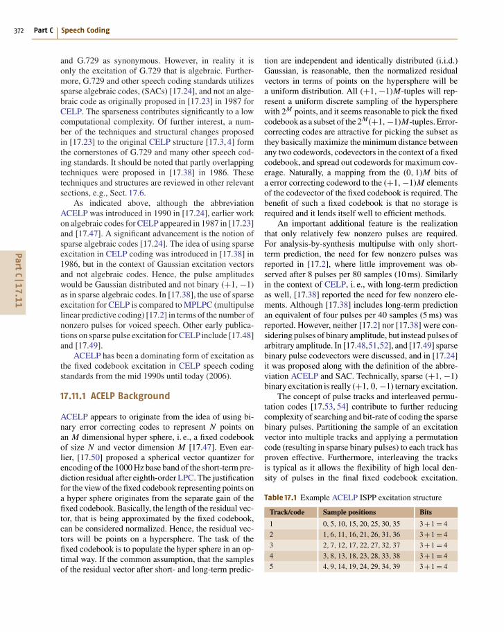
372 Part C Speech Coding
and G.729 as synonymous. However, in reality it isonly the excitation of G.729 that is algebraic. Further-more, G.729 and other speech coding standards utilizessparse algebraic codes, (SACs) [17.24], and not an alge-braic code as originally proposed in [17.23] in 1987 forCELP. The sparseness contributes significantly to a lowcomputational complexity. Of further interest, a num-ber of the techniques and structural changes proposedin [17.23] to the original CELP structure [17.3, 4] formthe cornerstones of G.729 and many other speech cod-ing standards. It should be noted that partly overlappingtechniques were proposed in [17.38] in 1986. Thesetechniques and structures are reviewed in other relevantsections, e.g., Sect. 17.6.
As indicated above, although the abbreviationACELP was introduced in 1990 in [17.24], earlier workon algebraic codes for CELP appeared in 1987 in [17.23]and [17.47]. A significant advancement is the notion ofsparse algebraic codes [17.24]. The idea of using sparseexcitation in CELP coding was introduced in [17.38] in1986, but in the context of Gaussian excitation vectorsand not algebraic codes. Hence, the pulse amplitudeswould be Gaussian distributed and not binary (+1,−1)as in sparse algebraic codes. In [17.38], the use of sparseexcitation for CELP is compared to MPLPC (multipulselinear predictive coding) [17.2] in terms of the number ofnonzero pulses for voiced speech. Other early publica-tions on sparse pulse excitation for CELP include [17.48]and [17.49].
ACELP has been a dominating form of excitation asthe fixed codebook excitation in CELP speech codingstandards from the mid 1990s until today (2006).
17.11.1 ACELP Background
ACELP appears to originate from the idea of using bi-nary error correcting codes to represent N points onan M dimensional hyper sphere, i. e., a fixed codebookof size N and vector dimension M [17.47]. Even ear-lier, [17.50] proposed a spherical vector quantizer forencoding of the 1000 Hz base band of the short-term pre-diction residual after eighth-order LPC. The justificationfor the view of the fixed codebook representing points ona hyper sphere originates from the separate gain of thefixed codebook. Basically, the length of the residual vec-tor, that is being approximated by the fixed codebook,can be considered normalized. Hence, the residual vec-tors will be points on a hypersphere. The task of thefixed codebook is to populate the hyper sphere in an op-timal way. If the common assumption, that the samplesof the residual vector after short- and long-term predic-
tion are independent and identically distributed (i.i.d.)Gaussian, is reasonable, then the normalized residualvectors in terms of points on the hypersphere will bea uniform distribution. All (+1,−1)M-tuples will rep-resent a uniform discrete sampling of the hyperspherewith 2M points, and it seems reasonable to pick the fixedcodebook as a subset of the 2M(+1,−1)M-tuples. Error-correcting codes are attractive for picking the subset asthey basically maximize the minimum distance betweenany two codewords, codevectors in the context of a fixedcodebook, and spread out codewords for maximum cov-erage. Naturally, a mapping from the (0, 1)M bits ofa error correcting codeword to the (+1,−1)M elementsof the codevector of the fixed codebook is required. Thebenefit of such a fixed codebook is that no storage isrequired and it lends itself well to efficient methods.
An important additional feature is the realizationthat only relatively few nonzero pulses are required.For analysis-by-synthesis multipulse with only short-term prediction, the need for few nonzero pulses wasreported in [17.2], where little improvement was ob-served after 8 pulses per 80 samples (10 ms). Similarlyin the context of CELP, i. e., with long-term predictionas well, [17.38] reported the need for few nonzero ele-ments. Although [17.38] includes long-term predictionan equivalent of four pulses per 40 samples (5 ms) wasreported. However, neither [17.2] nor [17.38] were con-sidering pulses of binary amplitude, but instead pulses ofarbitrary amplitude. In [17.48,51,52], and [17.49] sparsebinary pulse codevectors were discussed, and in [17.24]it was proposed along with the definition of the abbre-viation ACELP and SAC. Technically, sparse (+1,−1)binary excitation is really (+1, 0,−1) ternary excitation.
The concept of pulse tracks and interleaved permu-tation codes [17.53, 54] contribute to further reducingcomplexity of searching and bit-rate of coding the sparsebinary pulses. Partitioning the sample of an excitationvector into multiple tracks and applying a permutationcode (resulting in sparse binary pulses) to each track hasproven effective. Furthermore, interleaving the tracksis typical as it allows the flexibility of high local den-sity of pulses in the final fixed codebook excitation.
Table 17.1 Example ACELP ISPP excitation structure
Track/code Sample positions Bits
1 0, 5, 10, 15, 20, 25, 30, 35 3+1 = 4
2 1, 6, 11, 16, 21, 26, 31, 36 3+1 = 4
3 2, 7, 12, 17, 22, 27, 32, 37 3+1 = 4
4 3, 8, 13, 18, 23, 28, 33, 38 3+1 = 4
5 4, 9, 14, 19, 24, 29, 34, 39 3+1 = 4
PartC
17.1
1
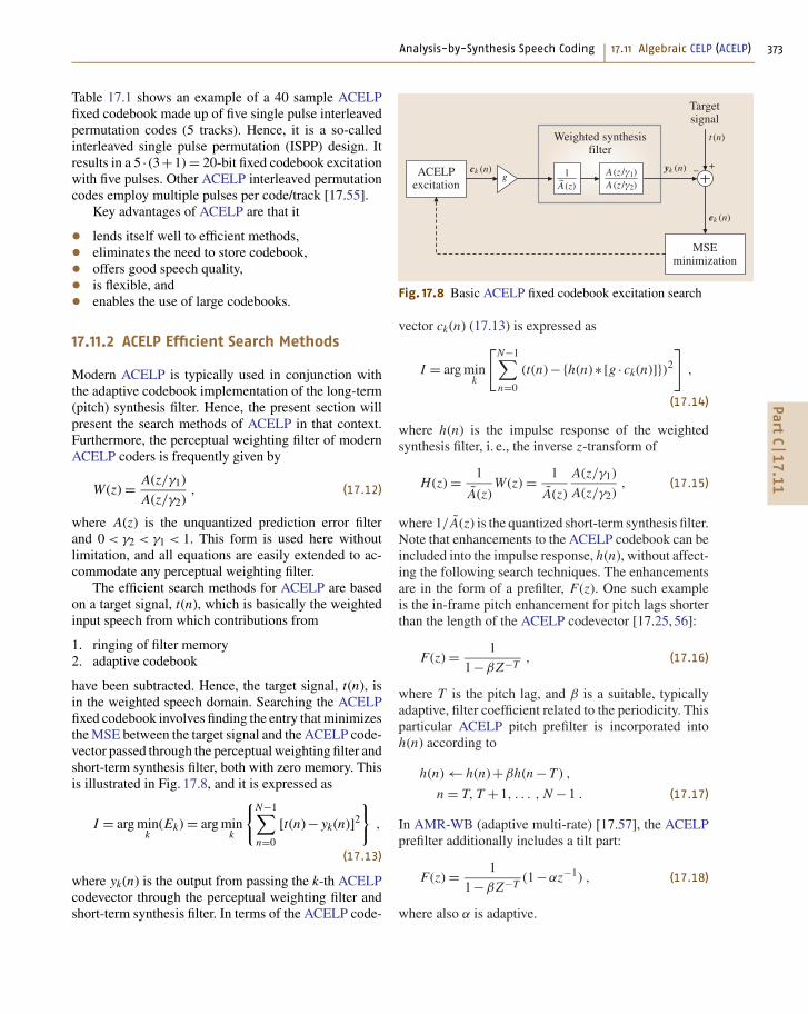
Analysis-by-Synthesis Speech Coding 17.11 Algebraic CELP (ACELP) 373
Table 17.1 shows an example of a 40 sample ACELPfixed codebook made up of five single pulse interleavedpermutation codes (5 tracks). Hence, it is a so-calledinterleaved single pulse permutation (ISPP) design. Itresults in a 5 · (3+1) = 20-bit fixed codebook excitationwith five pulses. Other ACELP interleaved permutationcodes employ multiple pulses per code/track [17.55].
Key advantages of ACELP are that it
• lends itself well to efficient methods,• eliminates the need to store codebook,• offers good speech quality,• is flexible, and• enables the use of large codebooks.
17.11.2 ACELP Efficient Search Methods
Modern ACELP is typically used in conjunction withthe adaptive codebook implementation of the long-term(pitch) synthesis filter. Hence, the present section willpresent the search methods of ACELP in that context.Furthermore, the perceptual weighting filter of modernACELP coders is frequently given by
W(z) = A(z/γ1)
A(z/γ2), (17.12)
where A(z) is the unquantized prediction error filterand 0 < γ2 < γ1 < 1. This form is used here withoutlimitation, and all equations are easily extended to ac-commodate any perceptual weighting filter.
The efficient search methods for ACELP are basedon a target signal, t(n), which is basically the weightedinput speech from which contributions from
1. ringing of filter memory2. adaptive codebook
have been subtracted. Hence, the target signal, t(n), isin the weighted speech domain. Searching the ACELPfixed codebook involves finding the entry that minimizesthe MSE between the target signal and the ACELP code-vector passed through the perceptual weighting filter andshort-term synthesis filter, both with zero memory. Thisis illustrated in Fig. 17.8, and it is expressed as
I = arg mink
(Ek) = arg mink
{N−1∑
n=0
[t(n)− yk(n)]2
},
(17.13)
where yk(n) is the output from passing the k-th ACELPcodevector through the perceptual weighting filter andshort-term synthesis filter. In terms of the ACELP code-
*��(�����!������"�����
= �(����(� �
2 )������� ����
>')������� ����
� �� #
�����
� �� $�#�� �� $�.�
�����
�����
�����
��
Fig. 17.8 Basic ACELP fixed codebook excitation search
vector ck(n) (17.13) is expressed as
I = arg mink
[N−1∑
n=0
(t(n)−{h(n)∗ [g · ck(n)]})2
],
(17.14)
where h(n) is the impulse response of the weightedsynthesis filter, i. e., the inverse z-transform of
H(z) = 1
A(z)W(z) = 1
A(z)
A(z/γ1)
A(z/γ2), (17.15)
where 1/ A(z) is the quantized short-term synthesis filter.Note that enhancements to the ACELP codebook can beincluded into the impulse response, h(n), without affect-ing the following search techniques. The enhancementsare in the form of a prefilter, F(z). One such exampleis the in-frame pitch enhancement for pitch lags shorterthan the length of the ACELP codevector [17.25, 56]:
F(z) = 1
1−βZ−T, (17.16)
where T is the pitch lag, and β is a suitable, typicallyadaptive, filter coefficient related to the periodicity. Thisparticular ACELP pitch prefilter is incorporated intoh(n) according to
h(n) ← h(n)+βh(n − T ) ,
n = T, T +1, . . . , N −1 . (17.17)
In AMR-WB (adaptive multi-rate) [17.57], the ACELPprefilter additionally includes a tilt part:
F(z) = 1
1−βZ−T(1−αz−1) , (17.18)
where also α is adaptive.
PartC
17.1
1
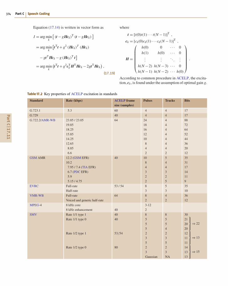
374 Part C Speech Coding
Equation (17.14) is written in vector form as
I = arg mink
[(t − gHck)
T (t − gHck)]
= arg mink
[tTt + g2 (Hck)
T (Hck)
− gtT Hck − g (Hck)T t
]
= arg mink
(tTt + g2cT
k HT Hck −2gtT Hck),
(17.19)
Table 17.2 Key properties of ACELP excitation in standards
Standard Rate (kbps) ACELP frame Pulses Tracks Bitssize (samples)
G.723.1 5.3 60 4 4 17
G.729 40 4 4 17
G.722.2/AMR-WB 23.85 / 23.05 64 24 4 88
19.85 18 4 72
18.25 16 4 64
15.85 12 4 52
14.25 10 4 44
12.65 8 4 36
8.85 4 4 20
6.6 2 2 12
GSM AMR 12.2 (GSM EFR) 40 10 5 35
10.2 8 4 31
7.95 / 7.4 (TIA EFR) 4 4 17
6.7 (PDC EFR) 3 3 14
5.9 2 2 11
5.15 / 4.75 2 5 9
EVRC Full-rate 53 / 54 8 5 35
Half-rate 3 3 10
VMR-WB Full-rate 64 8 4 36
Voiced and generic half-rate 2 2 12
MPEG-4 8 kHz core 3-12
8 kHz enhancement 40 2
SMV Rate 1/1 type 1 40 8 8 30
Rate 1/1 type 0 40 5
5
5
5
5
4
21
20
20
⎫⎪⎬
⎪⎭⇒ 22
Rate 1/2 type 1 53/54 2
3
5
2
3
5
12
11
11
⎫⎪⎬
⎪⎭⇒ 13
Rate 1/2 type 0 80 2
3
Gaussian
2
3
NA
14
13
13
⎫⎪⎬
⎪⎭⇒ 15
where
t = [t(0)t(1) · · · t(N −1)]T ,
ck = [ck(0)ck(1) · · · ck(N −1)]T ,
H =
⎛⎜⎜⎜⎜⎜⎜⎝
h(0) 0 · · · 0
h(1) h(0) · · · 0...
.... . .
...
h(N −2) h(N −3) · · · 0
h(N −1) h(N −2) · · · h(0)
⎞⎟⎟⎟⎟⎟⎟⎠
.
According to common procedure in ACELP, the excita-tion, ck, is found under the assumption of optimal gain g.
PartC
17.1
1

Analysis-by-Synthesis Speech Coding 17.11 Algebraic CELP (ACELP) 375
The gain is determined by minimizing the error energy:
∂Ek
∂g= ∂
∂g
(tTt + g2cT
k HT Hck −2gtT Hck) = 0
⇓g = tT Hck
cTk HT Hck
. (17.20)
Inserting this result in (17.19) yields
I = arg mink
(tTt −
(tT Hck
)2
cTk HT Hck
). (17.21)
Since t is independent of the codevector, ck, this isequivalent to
I = arg maxk
( (tT Hck
)2
cTk HT Hck
). (17.22)
The numerator is often rewritten in terms of the back-ward filtered target vector [17.23,53], tb = HTt, and thesearch is expressed as
I = arg maxk
( (tTb ck
)2
cTk HT Hck
)= arg max
k
((tTb ck
)2
cTk Φck
),
(17.23)
where Φ = HT H is symmetric and contains the auto-correlation of the impulse response of H(z):
Φ(i, j) =
⎧⎪⎨
⎪⎩
N−1−i∑l=0
h(l)h(l + i − j) , j ≤ i
Φ( j, i) , j > i
.
(17.24)
The backward filtered target tb and the autocorrelationmatrix Φ are calculated prior to searching the ACELPcodebook.
The efficient search methods all explore ways tomost efficiently evaluate (17.23), either in a mathemat-ically equivalent way, or in a slightly suboptimal waywith only minor sacrifice in performance. The followingsubsections will present some of the methods typicallyused in ACELP.
Sparse ACELPIn sparse ACELP only relatively few pulses are nonzero,and if they are binary, the nonzero pulses take on an
amplitude of ±1. The P pulses, P < N , are describeduniquely by the location and amplitude, mi and ai ,respectively, i = 0, 1, . . . , P −1. Note that ai = ±1.With this notation, the search of (17.23) can be writtenas [17.53]
I = arg maxm×a
⎛⎜⎜⎝
(P−1∑i=0
tb(mi )ai
)2
P−1∑i=0
Φ(mi ,mi )+2P−2∑i=0
P−1∑j=i+1
ai a jΦ(mi ,m j )
⎞⎟⎟⎠ ,
(17.25)
where the search is identifying the optimal P pulsepositions m = (m0, m1, . . . , m P−1) and P amplitudesa = (a0, a1, . . . , aP−1). This search can be performedin a nested loop so that the addition of one more pulse isconsidered in each loop. At the inner most loop, the finalcost function for a given candidate is calculated by oneadditional addition and the square to get the numerator,and P additional additions and one multiplication to getthe numerator. This provides for a very efficient exhaus-tive search, but as the size of the codebook increases thisquickly becomes impractical [17.53]. Sparse ACELP isused in all ACELP standards.
A Priori SignStudying the numerator of (17.25) it is evident that thecross correlation will be maximized by setting the pulseamplitudes, a, basically the pulse signs, to be the sameas the sign of the backward filtered target, tb [17.58].Accordingly, by setting the pulse signs a priori only thepulse locations m need to searched. This is achievedby incorporating the a priori pulse signs into the back-ward filtering target and correlation matrix prior to thesearch [17.58] according to:
tb(n) = |tb(n)| , (17.26)
Φ(i, j) = sign[tb(i)]sign[tb( j)]Φ(i, j) . (17.27)
and performing the search for pulse positions accordingto
I = arg maxm
⎛⎜⎜⎝
(P−1∑i=0
tb(mi )
)2
P−1∑i=0
Φ(mi ,mi )+2P−2∑i=0
P−1∑j=i+1
Φ(mi ,m j )
⎞⎟⎟⎠ ,
(17.28)
where, again, the search identifies the optimal P pulsepositions m = (m0, m1, . . . , m P−1). To eliminate themultiplication by 2 during the search, all off-diagonalelements of Φ(i, j) can be multiplied by 2 prior to thesearch. The a priori determination of the pulse signs is
PartC
17.1
1

376 Part C Speech Coding
Table 17.3 Effectiveness of ACELP focused search [17.53]
Percentage of exhaustive search SNR (dB)
100 22.20
4 22.14
1.6 22.00
0.2 22.05
0.15 21.83
0.05 21.80
0.03 21.50
not in general equivalent to the exhaustive search givenby (17.25). It is used in G.729 [17.46], G.723.1 [17.25],EVRC [17.26], and GSM-EFR [17.56] among others.Note that the presetting of the sign can be based onthe sign of a signal that is a linear combination ofthe backward filtered target and the long-term predic-tion residual [17.56] (or a similarly suitable signal), andhence not only based on the sign of the backward-filteredtarget.
Focused SearchVarious focused search methods exist [17.53, 54, 58].Generally, the P pulses are searched in nested loops andconstraints on the correlation,
C =p−2∑
i=0
tb(mi ) , p < P , (17.29)
are set up to disregard subsections of the ACELP code-book (represented by entry into the p-th loop) if thecorrelation C does not meet a predefined threshold.A table from [17.53] is reproduced in Table 17.3, il-lustrating this in the form of the relation between thepercentage of exhaustive search and the SNR for a sen-tence spoken by a female talker. The threshold can becalculated in various ways. It can be based on the max-imum possible correlation of the existing p−1 pulsecandidates, or the average correlation over their possiblepositions, or a combination thereof as in [17.58]. Gener-alizing [17.58] leads to a threshold based on maximumpulse correlation
Cmax =p−2∑
l=0
maxi∈Tl
[tb(i)
](17.30)
and average pulse correlation
Cavg =p−2∑
l=0
avgi∈Tl
[tb(i)
]. (17.31)
In (17.30) and (17.31), Tl is the set of possible pulse posi-tions of pulse l. The threshold can then be constructed asa combination of the maximum and average correlation:
Cthr = Cavg +αthr(Cmax −Cavg) . (17.32)
This will reduce the average complexity. To have a firmlimit on the worst-case complexity a threshold on thenumber of times a certain loop can be entered maybe enforced [17.58]. A very large part of the ACELPcodebook can be ruled out this way.
Depth-First Tree Search ProcedureAs the number of pulses P increases, additionalmethods can be used to search the effectively increas-ing codebook efficiently. One such method is usedin G.729 Annex A [17.59], GSM-EFR [17.56], andAMR-WB [17.57]. The depth-first tree search procedurewould typically be used instead of the focused search tofurther reduce complexity. The set of P pulses is di-vided into Nm subsets, typically with an equal numberof M pulses in each. While the subsets are searched se-quentially, the pulses in each subset are searched jointly.First subset 1, then subset 2, etc. Subsequent sets aresearched given the pulses of previous sets. This searchis performed iteratively, circulating the assignment ofpulses to tracks. For instance, at the first iteration thefirst two pulses can be assigned to tracks 0 and 1, whilefor the second iteration the first two pulses can be as-signed to tracks 2 and 3, etc. In the second iteration thelast two pulses can be assigned to tracks 0 and 1.
A reference signal may be constructed to assist in se-lecting a subset of pulse positions to consider in a giventrack. As an example, with pulses 0 and 1 being as-signed to tracks 2 and 3 (each of eight positions), basedon the reference signal, only four positions in track 2are preselected for consideration for pulse 0. Such pre-selection reduces complexity. Techniques like this canbe used to control the complexity and balance complex-ity of multiple rates in a speech coder. The AMR-WBspeech coder [17.57] provides a good example of thistechnique. The reference signal is typically identical tothe signal used to set the signs a priori (Sect. 17.11.2). Itcan be the backward filtered target signal as in [17.60],a linear combination of the backward filtered target andthe long-term prediction residual signals as in [17.57],or some other suitable signal.
In G.729A, the depth-first tree search is used insteadof the focused search of G.729 and provides a directcomparison. It results in a very significant saving of5 MIPS (million instructions per second) at the cost of
PartC
17.1
1

Analysis-by-Synthesis Speech Coding 17.12 Conjugate Structure CELP (CS-CELP) and CS-ACELP 377
a slight degradation in performance, about 0.2 dB SNRaccording to [17.60].
17.11.3 ACELP in Standards
A number of speech coding standards utilizes theACELP excitation, that is, the sparse binary pulseexcitation. In grouping by standards body: ITU-TG.723.1 [17.25] (ACELP for the 5.3 kbit/s rate, mul-tipulse for the 6.3 kbit/s rate), ITU-T G.729 [17.46],ITU-T G.722.2 [17.61], ETSI GSM-EFR (Euro-pean Telecommunications Standards Institute) [17.56],ETSI/3GPP GSM AMR (3-rd Generation PartnershipProject) [17.62], 3GPP GSM AMR-WB [17.57], TIA-127 EVRC (enhanced variable rate codec) [17.26],TIA-136 EFR [17.63], TIA/3GPP2 SMV [17.64],3GPP2 VMR-WB [17.28], ARIB PDC-EFR (Associ-ation of Radio Industries and Businesses), and MPEG-4CELP (Moving Pictures Expert Group) narrow-bandaudio [17.65].
It should be noted that ITU-T G.722.2 and 3GPPGSM AMR WB is the same wide-band multirate speech
coder. It was initially standardized for cellular by 3GPPand subsequently submitted to the ITU for considerationin an, at the time, ongoing standardization effort of wide-band coding of speech at around 16 kbit/s. It shouldalso be noted that the AMR-WB rate of 12.65 kbit/s isinteroperable with one of the rates of 3GPP2 VMR-WB.Furthermore, the GSM EFR is identical to the 12.2 kbit/srate of ETSI/3GPP AMR, TIA-136 EFR is equivalentto the 7.4 kbit/s rate of AMR, and ARIB PDC-EFRis equivalent to the 6.7 kbit/s rate of AMR. Note thatit can be somewhat confusing that multiple standardsbodies use the same acronym, EFR. The MPEG-4 CELPis really somewhat of a hybrid between ACELP andmultipulse as it doesn’t use binary or ternary pulses, butinstead apply a VQ of the pulse amplitudes. Similarly,TIA/3GPP2 SMV is a hybrid as it is based on sub-codebooks where most sub-codebooks are ACELP-like,but one is different, and the codebooks are weighteddifferently in selecting the overall best excitation.
Table 17.2 summarizes some of the key propertiesof the ACELP fixed codebook excitation structures usedin the standards listed above.
17.12 Conjugate Structure CELP (CS-CELP) and CS-ACELPConjugate structure CELP (CS-CELP) introduces con-jugate structure VQ for CELP. It was originally proposedin [17.66] for CELP. However, earlier the conjugatestructure was used in other coders, e.g., in transformcoding [17.67]. Generally, conjugate structure VQ con-structs the output codevector ci, j as a linear combinationof the output codevectors from two codebooks ci and c jrespectively:
ci, j = α1 · ci +α2 · c j . (17.33)
The advantages of the conjugate structure compared toa single VQ is threefold [17.66]:
• improves resilience to bit-errors,• reduces memory requirement,• facilitates reduced complexity methods.
These advantages are demonstrated in [17.66]and [17.68], which also present methods to train theconjugate structure codebooks. Furthermore, [17.66]and [17.68] present an 8 kb/s CS-CELP speech coderwhere the conjugate structure is used for both thefixed codebook excitation and the joint quantiza-tion of the subframe based adaptive codebook gain
and fixed codebook gain. This coder was submit-ted by NTT for the ITU-T (CCITT at the time)G.729 standardization. Although the coder was notstandardized as G.729, techniques from multiple can-didates were merged and eventually formed G.729.The resulting G.729 standard [17.46] uses the con-jugate structure for the 2-dimensional joint VQ ofthe subframe based adaptive codebook gain and fixedcodebook gain. In G.729 the linear combination ofthe codevectors from the two codebooks is a sim-ple summation, and the conjugate structure codevectoris
ci, j = ci + c j . (17.34)
One codebook has a bias towards the element corre-sponding to the fixed codebook gain, while the othercodebook has a bias towards the element correspondingto the adaptive codebook gain. This allows open-looppreselection of both codebooks based on the respectivedominant parameter. This leaves only a subset (a quarter)for the more-complex joint closed-loop search withoutany noticeable degradation compared to an exhaustiveclosed-loop search [17.58].
PartC
17.1
2
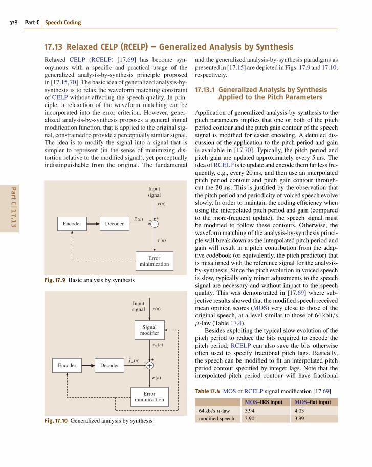
378 Part C Speech Coding
17.13 Relaxed CELP (RCELP) – Generalized Analysis by SynthesisRelaxed CELP (RCELP) [17.69] has become syn-onymous with a specific and practical usage of thegeneralized analysis-by-synthesis principle proposedin [17.15,70]. The basic idea of generalized analysis-by-synthesis is to relax the waveform matching constraintof CELP without affecting the speech quality. In prin-ciple, a relaxation of the waveform matching can beincorporated into the error criterion. However, gener-alized analysis-by-synthesis proposes a general signalmodification function, that is applied to the original sig-nal, constrained to provide a perceptually similar signal.The idea is to modify the signal into a signal that issimpler to represent (in the sense of minimizing dis-tortion relative to the modified signal), yet perceptuallyindistinguishable from the original. The fundamental
)������ 9������
�������(� �
)����������� ����
� �
����
� ��
�� ��
Fig. 17.9 Basic analysis by synthesis
)������ 9������
�������(� �
)����������� ����
� �
����
� ��
��� ��
�(� �����"���
�� ��
Fig. 17.10 Generalized analysis by synthesis
and the generalized analysis-by-synthesis paradigms aspresented in [17.15] are depicted in Figs. 17.9 and 17.10,respectively.
17.13.1 Generalized Analysis by SynthesisApplied to the Pitch Parameters
Application of generalized analysis-by-synthesis to thepitch parameters implies that one or both of the pitchperiod contour and the pitch gain contour of the speechsignal is modified for easier encoding. A detailed dis-cussion of the application to the pitch period and gainis available in [17.70]. Typically, the pitch period andpitch gain are updated approximately every 5 ms. Theidea of RCELP is to update and encode them far less fre-quently, e.g., every 20 ms, and then use an interpolatedpitch period contour and pitch gain contour through-out the 20 ms. This is justified by the observation thatthe pitch period and periodicity of voiced speech evolveslowly. In order to maintain the coding efficiency whenusing the interpolated pitch period and gain (comparedto the more-frequent update), the speech signal mustbe modified to follow these contours. Otherwise, thewaveform matching of the analysis-by-synthesis princi-ple will break down as the interpolated pitch period andgain will result in a pitch contribution from the adap-tive codebook (or equivalently, the pitch predictor) thatis misaligned with the reference signal for the analysis-by-synthesis. Since the pitch evolution in voiced speechis slow, typically only minor adjustments to the speechsignal are necessary and without impact to the speechquality. This was demonstrated in [17.69] where sub-jective results showed that the modified speech receivedmean opinion scores (MOS) very close to those of theoriginal speech, at a level similar to those of 64 kbit/sµ-law (Table 17.4).
Besides exploiting the typical slow evolution of thepitch period to reduce the bits required to encode thepitch period, RCELP can also save the bits otherwiseoften used to specify fractional pitch lags. Basically,the speech can be modified to fit an interpolated pitchperiod contour specified by integer lags. Note that theinterpolated pitch period contour will have fractional
Table 17.4 MOS of RCELP signal modification [17.69]
MOS–IRS input MOS–flat input
64 kb/s µ-law 3.94 4.03
modified speech 3.90 3.99
PartC
17.1
3
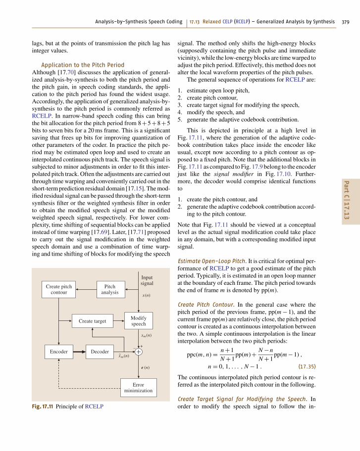
Analysis-by-Synthesis Speech Coding 17.13 Relaxed CELP (RCELP) – Generalized Analysis by Synthesis 379
lags, but at the points of transmission the pitch lag hasinteger values.
Application to the Pitch PeriodAlthough [17.70] discusses the application of general-ized analysis-by-synthesis to both the pitch period andthe pitch gain, in speech coding standards, the appli-cation to the pitch period has found the widest usage.Accordingly, the application of generalized analysis-by-synthesis to the pitch period is commonly referred asRCELP. In narrow-band speech coding this can bringthe bit allocation for the pitch period from 8+5+8+5bits to seven bits for a 20 ms frame. This is a significantsaving that frees up bits for improving quantization ofother parameters of the coder. In practice the pitch pe-riod may be estimated open loop and used to create aninterpolated continuous pitch track. The speech signal issubjected to minor adjustments in order to fit this inter-polated pitch track. Often the adjustments are carried outthrough time warping and conveniently carried out in theshort-term prediction residual domain [17.15]. The mod-ified residual signal can be passed through the short-termsynthesis filter or the weighted synthesis filter in orderto obtain the modified speech signal or the modifiedweighted speech signal, respectively. For lower com-plexity, time shifting of sequential blocks can be appliedinstead of time warping [17.69]. Later, [17.71] proposedto carry out the signal modification in the weightedspeech domain and use a combination of time warp-ing and time shifting of blocks for modifying the speech
)������ 9������
2���"!�����
)����������� ����
� �
����
�������(� �
���� � �!���
'�� ��������������
��� ��
�� ��
'�� ���� �(��
� ��
Fig. 17.11 Principle of RCELP
signal. The method only shifts the high-energy blocks(supposedly containing the pitch pulse and immediatevicinity), while the low-energy blocks are time warped toadjust the pitch period. Effectively, this method does notalter the local waveform properties of the pitch pulses.
The general sequence of operations for RCELP are:
1. estimate open loop pitch,2. create pitch contour,3. create target signal for modifying the speech,4. modify the speech, and5. generate the adaptive codebook contribution.
This is depicted in principle at a high level inFig. 17.11, where the generation of the adaptive code-book contribution takes place inside the encoder likeusual, except now according to a pitch contour as op-posed to a fixed pitch. Note that the additional blocks inFig. 17.11 as compared to Fig. 17.9 belong to the encoderjust like the signal modifier in Fig. 17.10. Further-more, the decoder would comprise identical functionsto
1. create the pitch contour, and2. generate the adaptive codebook contribution accord-
ing to the pitch contour.
Note that Fig. 17.11 should be viewed at a conceptuallevel as the actual signal modification could take placein any domain, but with a corresponding modified inputsignal.
Estimate Open-Loop Pitch. It is critical for optimal per-formance of RCELP to get a good estimate of the pitchperiod. Typically, it is estimated in an open loop mannerat the boundary of each frame. The pitch period towardsthe end of frame m is denoted by pp(m).
Create Pitch Contour. In the general case where thepitch period of the previous frame, pp(m −1), and thecurrent frame pp(m) are relatively close, the pitch periodcontour is created as a continuous interpolation betweenthe two. A simple continuous interpolation is the linearinterpolation between the two pitch periods:
ppc(m, n) = n +1
N +1pp(m)+ N −n
N +1pp(m −1) ,
n = 0, 1, . . . , N −1 . (17.35)
The continuous interpolated pitch period contour is re-ferred as the interpolated pitch contour in the following.
Create Target Signal for Modifying the Speech. Inorder to modify the speech signal to follow the in-
PartC
17.1
3
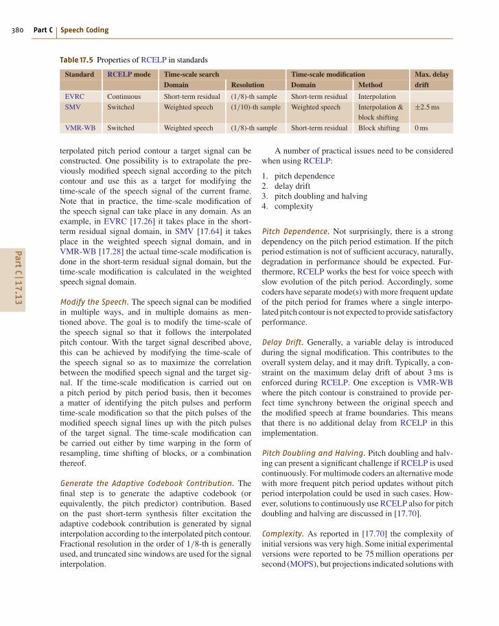
380 Part C Speech Coding
Table 17.5 Properties of RCELP in standards
Standard RCELP mode Time-scale search Time-scale modification Max. delay
Domain Resolution Domain Method drift
EVRC Continuous Short-term residual (1/8)-th sample Short-term residual Interpolation
SMV Switched Weighted speech (1/10)-th sample Weighted speech Interpolation & ±2.5 ms
block shifting
VMR-WB Switched Weighted speech (1/8)-th sample Short-term residual Block shifting 0 ms
terpolated pitch period contour a target signal can beconstructed. One possibility is to extrapolate the pre-viously modified speech signal according to the pitchcontour and use this as a target for modifying thetime-scale of the speech signal of the current frame.Note that in practice, the time-scale modification ofthe speech signal can take place in any domain. As anexample, in EVRC [17.26] it takes place in the short-term residual signal domain, in SMV [17.64] it takesplace in the weighted speech signal domain, and inVMR-WB [17.28] the actual time-scale modification isdone in the short-term residual signal domain, but thetime-scale modification is calculated in the weightedspeech signal domain.
Modify the Speech. The speech signal can be modifiedin multiple ways, and in multiple domains as men-tioned above. The goal is to modify the time-scale ofthe speech signal so that it follows the interpolatedpitch contour. With the target signal described above,this can be achieved by modifying the time-scale ofthe speech signal so as to maximize the correlationbetween the modified speech signal and the target sig-nal. If the time-scale modification is carried out ona pitch period by pitch period basis, then it becomesa matter of identifying the pitch pulses and performtime-scale modification so that the pitch pulses of themodified speech signal lines up with the pitch pulsesof the target signal. The time-scale modification canbe carried out either by time warping in the form ofresampling, time shifting of blocks, or a combinationthereof.
Generate the Adaptive Codebook Contribution. Thefinal step is to generate the adaptive codebook (orequivalently, the pitch predictor) contribution. Basedon the past short-term synthesis filter excitation theadaptive codebook contribution is generated by signalinterpolation according to the interpolated pitch contour.Fractional resolution in the order of 1/8-th is generallyused, and truncated sinc windows are used for the signalinterpolation.
A number of practical issues need to be consideredwhen using RCELP:
1. pitch dependence2. delay drift3. pitch doubling and halving4. complexity
Pitch Dependence. Not surprisingly, there is a strongdependency on the pitch period estimation. If the pitchperiod estimation is not of sufficient accuracy, naturally,degradation in performance should be expected. Fur-thermore, RCELP works the best for voice speech withslow evolution of the pitch period. Accordingly, somecoders have separate mode(s) with more frequent updateof the pitch period for frames where a single interpo-lated pitch contour is not expected to provide satisfactoryperformance.
Delay Drift. Generally, a variable delay is introducedduring the signal modification. This contributes to theoverall system delay, and it may drift. Typically, a con-straint on the maximum delay drift of about 3 ms isenforced during RCELP. One exception is VMR-WBwhere the pitch contour is constrained to provide per-fect time synchrony between the original speech andthe modified speech at frame boundaries. This meansthat there is no additional delay from RCELP in thisimplementation.
Pitch Doubling and Halving. Pitch doubling and halv-ing can present a significant challenge if RCELP is usedcontinuously. For multimode coders an alternative modewith more frequent pitch period updates without pitchperiod interpolation could be used in such cases. How-ever, solutions to continuously use RCELP also for pitchdoubling and halving are discussed in [17.70].
Complexity. As reported in [17.70] the complexity ofinitial versions was very high. Some initial experimentalversions were reported to be 75 million operations persecond (MOPS), but projections indicated solutions with
PartC
17.1
3
Analysis-by-Synthesis Speech Coding 17.14 eX-CELP 381
a complexity of about 15 MOPS would be achievable.Such solutions have since materialized in the form ofstandards such as EVRC, SMV, and VMR-WB whichare all around 40 weighted MOPS (WMOPS) or less forfull duplex encoding and decoding.
17.13.2 RCELP in Standards
RCELP is utilized in a number of standards to efficientlyrepresent the pitch period: TIA-127 EVRC [17.26],
TIA/3GPP2 SMV [17.64], 3GPP2 VMR-WB [17.28],and it was part of a proposal for the ITU-T 4 kb/sstandardization effort [17.8] before that effort was aban-doned by the ITU. Although, those standards implementRCELP in different ways and variations, they all achievethe same goal of reducing the bit rate required to repre-sent the pitch period. Some apply RCELP continuouslywhile others apply RCELP only for specific modes.Some of the RCELP features of these standards aresummarized in Table 17.5.
17.14 eX-CELP
The eXtended CELP (eX-CELP) technique [17.71] ismore a collection of techniques or a general approachthan a single specific technique. The general idea isto emphasize the perceptual important features duringencoding within the context of analysis-by-synthesis.Basically, the closed-loop waveform matching ofanalysis-by-synthesis is relaxed by combining open-loop and closed-loop control. The necessity to relaxthe strict waveform matching originates from the ob-servation that at low bit rate it is not possible to achievetoll quality through strict waveform matching, and in-stead emphasis on the perceptually important features isnecessary. This is achieved by incorporating signal clas-sification into weighting, using RCELP-like techniques,combining open-loop and closed-loop, designing thefixed codebook with multiple sub-codebooks addressingdifferent signal characteristics, and utilizing multimodeencoding.
Signal Classification. eX-CELP uses elaborate signalclassification. As many as six classes are used [17.27]:
• silence/background noise• stationary unvoiced• nonstationary unvoiced• onset• nonstationary voiced• stationary voiced
The classification takes place in multiple stages and isrefined as information becomes available in the algo-rithm.
Signal Modification. The signal modification algo-rithm not only modifies the pitch contour to allowa lower bit rate for the encoding of the pitch periodlike RCELP, it also modifies the speech signal to in-
crease the pitch contribution of the adaptive codebook.According to [17.71], it uses waveform interpolation orharmonic smoothing to pre-smooth voiced transition ar-eas in an open-loop manner. This results in faster buildupof the adaptive codebook. The underlying objective isto increase/enhance the pitch contribution as much aspossible without introducing noticeable distortion to thesignal.
Combination of Open-Loop and Closed-Loop. Thealgorithm combines open-loop and closed-loop exten-sively. One example is the gain quantization. It is wellknown that for background noise, accurate waveformmatching is not necessary for a perceptual accurate re-production. However, features such as a natural (smooth)energy contour and a dense excitation is more important.Hence, in the presence of background noise the gainquantization favors open-loop over close-loop, and itaims at maintaining a smooth energy contour. Similarly,it would favor selection of excitation from a relativelydenser codebook.
Fixed Codebook. The fixed codebook is made up of mul-tiple sub-codebooks of varying pulse density and evena sub-codebook of dense random-like noise. Each sub-codebook is designed and tuned with a certain type ofsignal or speech in mind. Each codebook is generallysearched according to the analysis-by-synthesis princi-ple, but the selection between the best outputs of thevarious sub-codebooks is influenced by the classifica-tion information, and other signal parameters such asestimate of background noise level and peakiness of thespeech.
Multimode. eX-CELP distinguishes between two fun-damentally different encoding modes, types 0 and 1.
PartC
17.1
4

382 Part C Speech Coding
Table 17.6 Key general features of type 0 and type 1 coding modes in eX-CELP
Entity Type 0 Type 1
Signal character All other Staitonary voiced
Subframes Fewer More
Pitch period (adaptive codebook) Subframe based Frame based
Fixed codebook Pulse & Gaussian sub-codebooks Pulse sub-codebooks
Adaptive codebook gains Joint 2-D VQ (subframe based) A priori VQ (frame based)
Fixed codebook gains Joint 2-D VQ (subframe based) A posteriori VQ (frame based)
Table 17.7 MOS of SMV at various operating points [17.71]
Coder Average MOS MOSbit rate (clean (noisy
speech) speech)
EVRC x 3.58 3.35
SMV Mode 0 1.0 · x 3.90 3.57
SMV Mode 1 0.71 · x 3.64 3.53
SMV Mode 2 0.56/0.60 · x 3.46 3.53
Table 17.8 MOS of 4 kbit/s eX-CELP [17.8]
Input Coder MOS
MIRS G.726 3.14
(modified intermediate G.729 3.43
reference system) 4 kb/s eX-CELP 3.36
Flat G.726 3.12
G.729 3.27
4 kb/s eX-CELP 3.32
The bit allocation, the quantization methods, and eventhe subframe structure for the two modes can be dif-ferent. In type 1, targeting stationary voiced speech,the subframe adaptive codebook gains are prequan-tized open-loop using VQ prior to subframe processing,while fixed codebook gains are left unquantized dur-
ing subframe processing and quantized jointly usingVQ after subframe processing is complete. For type 0,a more-conventional joint two-dimensional VQ of thesubframe based adaptive and fixed codebook gains isused. However, the gain estimation and quantization isstill not strictly analysis-by-synthesis for type 0, as fo-cus remains on producing a perceptually faithful output,mixing open-loop and closed-loop. Key general featuresof the two types are listed in Table 17.6.
17.14.1 eX-CELP in Standards
The 3GPP2 SMV standard [17.64] is based oneX-CELP. Table 17.7 is reproduced from [17.71]and compares the MOS scores of SMV at vari-ous operating points of quality versus average bitrate with EVRC. The third column contains theMOS scores for clean speech, and the fourth columncontains the MOS scores of speech in backgroundnoise. Also one of the promising ITU-T 4 kbit/scandidates [17.8] was based on eX-CELP. SomeMOS scores comparing the performance to 32 kbit/sG.726 and 8 kbit/s G.729 are reproduced in Ta-ble 17.8.
17.15 iLBC
The iLBC coder [17.31, 32] is quite different fromother analysis-by-synthesis speech coders. Most otheranalysis-by-synthesis speech coders use a long-term pre-dictor or an adaptive codebook continuously and acrossthe frame boundaries. Due to the relatively large bulkdelay in repeating the previous waveform stored in thelong-term predictor memory or the adaptive codebook,if a frame is lost, the degrading effect tends to propa-gate a while. The iLBC coder attempts to address thisissue and improve the robustness against frame loss. Itachieves this by employing block-independent codingof the adaptive codebook. In other words, the adaptivecodebook of each speech frame is encoded independent
of the previous frames. Therefore, if a frame is lost,the quality degrading effect due to a mismatched adap-tive codebook is limited to the lost frame and will notpropagate to the future frames.
Of course, the improved robustness does not comefor free. By not allowing the adaptive codebook to beused across the frame boundaries, the iLBC coder givesup the opportunity to exploit the corresponding long-term redundancy in the speech signal across the frameboundaries. Therefore, for clear channel it inevitablysacrifices the output speech quality to some extent whencompared with more-conventional CELP coders. In ef-fect, the iLBC coder makes a trade-off between the
PartC
17.1
5
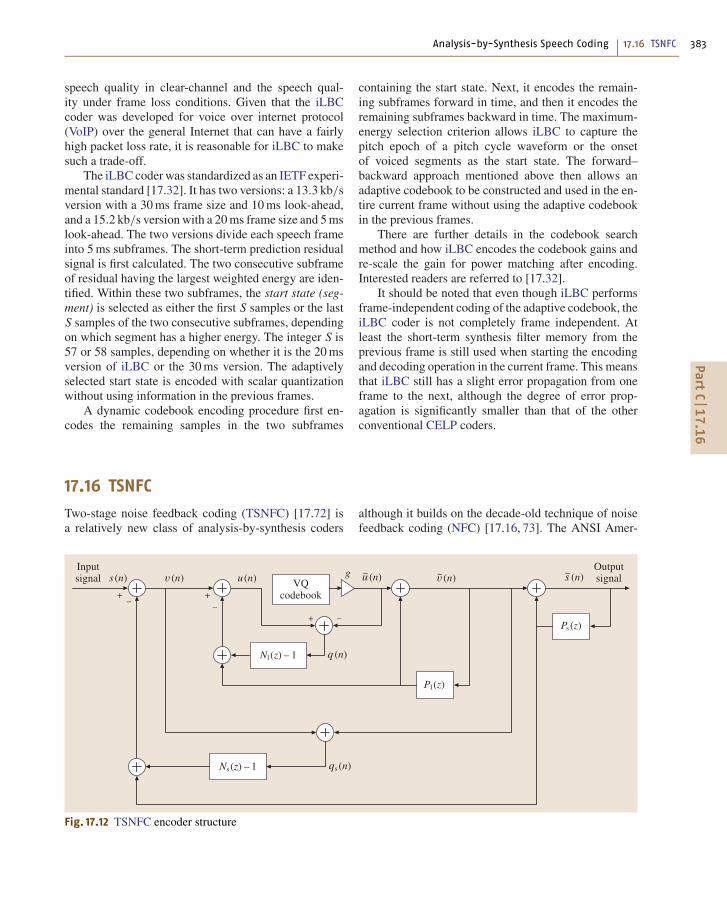
Analysis-by-Synthesis Speech Coding 17.16 TSNFC 383
speech quality in clear-channel and the speech qual-ity under frame loss conditions. Given that the iLBCcoder was developed for voice over internet protocol(VoIP) over the general Internet that can have a fairlyhigh packet loss rate, it is reasonable for iLBC to makesuch a trade-off.
The iLBC coder was standardized as an IETF experi-mental standard [17.32]. It has two versions: a 13.3 kb/sversion with a 30 ms frame size and 10 ms look-ahead,and a 15.2 kb/s version with a 20 ms frame size and 5 mslook-ahead. The two versions divide each speech frameinto 5 ms subframes. The short-term prediction residualsignal is first calculated. The two consecutive subframeof residual having the largest weighted energy are iden-tified. Within these two subframes, the start state (seg-ment) is selected as either the first S samples or the lastS samples of the two consecutive subframes, dependingon which segment has a higher energy. The integer S is57 or 58 samples, depending on whether it is the 20 msversion of iLBC or the 30 ms version. The adaptivelyselected start state is encoded with scalar quantizationwithout using information in the previous frames.
A dynamic codebook encoding procedure first en-codes the remaining samples in the two subframes
containing the start state. Next, it encodes the remain-ing subframes forward in time, and then it encodes theremaining subframes backward in time. The maximum-energy selection criterion allows iLBC to capture thepitch epoch of a pitch cycle waveform or the onsetof voiced segments as the start state. The forward–backward approach mentioned above then allows anadaptive codebook to be constructed and used in the en-tire current frame without using the adaptive codebookin the previous frames.
There are further details in the codebook searchmethod and how iLBC encodes the codebook gains andre-scale the gain for power matching after encoding.Interested readers are referred to [17.32].
It should be noted that even though iLBC performsframe-independent coding of the adaptive codebook, theiLBC coder is not completely frame independent. Atleast the short-term synthesis filter memory from theprevious frame is still used when starting the encodingand decoding operation in the current frame. This meansthat iLBC still has a slight error propagation from oneframe to the next, although the degree of error prop-agation is significantly smaller than that of the otherconventional CELP coders.
17.16 TSNFC
Two-stage noise feedback coding (TSNFC) [17.72] isa relatively new class of analysis-by-synthesis coders
��
��
�
��
��
� �� �� ��<���������
�� ��
� ��
�������(� � � ��
�� ���
�� ���
� ��/�������(� �
�� ��� � #
�� ���� ��� � #
Fig. 17.12 TSNFC encoder structure
although it builds on the decade-old technique of noisefeedback coding (NFC) [17.16, 73]. The ANSI Amer-
PartC
17.1
6

384 Part C Speech Coding
ican national standard BV16 coder [17.33] and thesimilar wide-band version BV32 are based on TSNFC.While the original NFC uses sample based quantiza-tion of the excitation signal and has less in commonwith analysis-by-synthesis, the recent extension of NFCto TSNFC and the development of CELP-like VQtechniques [17.72, 74] for vector quantization of theexcitation signal have created a commonality betweenTSNFC and CELP, making a brief overview in thecontext of analysis-by-synthesis relevant.
One structure for TSNFC is shown in Fig. 17.12. Itclearly looks nothing like a CELP coder, compare toFig. 17.5. The short-term predictor, Ps(z), is equivalentto the short-term predictor of CELP coders and resultsin a short-term prediction error filter given by
A(z) = 1− Ps(z) . (17.36)
Similarly, the long-term predictor Pl(z) corresponds tothe pitch predictor of CELP (or the adaptive codebook).Before TSNFC is described in more detail another in-teresting observation in relation to analysis-by-synthesiscan be made. Studying the TSNFC encoder structure inFig. 17.12 one can observe the decoder output speech,s(n), being generated as part of the quantization processof the excitation. Conceptually, every codevector of theVQ codebook is fed through the structure in Fig. 17.12and the candidate minimizing the MSE of q(n) is se-lected as the output of the VQ. With a short-term noisefeedback filter given by Ns(z)−1, minimizing the MSEof q(n) will result in a spectral envelope of the quantiza-tion noise, e(n) = s(n)− s(n) given by Ns(z). Hence, thespectral envelope of the coding noise can be controlleddirectly by Ns(z). This has a parallel to the CELP coderwhere the spectral envelope of the coding noise is con-
�� �
��
� �� �� ��<���������
�� ��
���� ��
� ��
�� ��� � #
�#
�� ���
��
���� ��
Fig. 17.13 TSNFC ZSR structure
trolled by the inverse of the perceptual weighting filter.Hence, a CELP coder with a perceptual weighting filterof
W(z) = A(z/γ1)
A(z/γ2), 0 < γ2 < γ1 < 1 , (17.37)
and a TSNFC coder with a short-term noise feedbackfilter of
Ns(z)−1 = A(z/γ2)
A(z/γ1)−1 , 0 < γ2 < γ1 < 1
(17.38)
will both result in a coding noise with a spectral envelopeshaped according to
Ns(z) = A(z/γ2)
A(z/γ1). (17.39)
Similarly, the TSNFC structure in Fig. 17.12 will resultin a coding noise with spectral fine structure shaped ac-cording to Nl(z). A suitable choice according to [17.33]is
Nl(z) = 1+βz−T , (17.40)
where β is the long-term noise feedback filter coefficientand T is the pitch period. Typically, β is adaptivelycontrolled by the pitch analysis, and 0 ≤ β ≤ 1.
Derivation of short-term predictor coefficients andquantization thereof can be carried out with appropri-ate techniques from the literature, similarly with theestimation and quantization of the long-term predictorparameters. The methods and structures for VQ of theexcitation and the similarities to analysis-by-synthesisin CELP coders will be discussed in more detail in thefollowing.
PartC
17.1
6

Analysis-by-Synthesis Speech Coding 17.16 TSNFC 385
17.16.1 Excitation VQ in TSNFC
Similar to CELP it is advantageous to apply the superpo-sition principle when calculating the error signal, q(n),for the excitation VQ. It is calculated as the superposi-tion of the zero state response (ZSR), qZSR(n), and thezero-input response (ZIR), qZIR(n) [17.72]. With a min-imum pitch lag being greater than the dimension of theexcitation VQ, the structure in Fig. 17.12 reduces to theZSR structure in Fig. 17.13. This structure is simplifiedas shown in Fig. 17.14 according to [17.74], where H(z)with the short-term noise feedback filter of (17.38) isgiven by
H(z) = QZSR(z)
U(z)= − 1
Ns(z)A(z)
= − A(z/γ1)
A(z/γ2)A(z). (17.41)
The ZIR structure is derived from Fig. 17.12 as shownin Fig. 17.15. Typically in TSNFC, a relatively short di-mension of the excitation VQ is used. In BV16 [17.33]a 4-dimensional excitation VQ is used. The frame sizeis 40 samples (5 ms) during which A(z) remains con-stant. Hence, the codebook needs only to be filteredwith H(z) according to Fig. 17.14 once per frame, orequivalently, once per 10 codebook searches. In otherwords, the filtered codebook is generated only once per10 codebook searches. The filtered codebook vectorsare denoted qZSR(k, n), where k indicates the code-book index, k = 0, 1, . . . , K −1. On the other hand,the ZIR, qZIR(n) needs to be generated for every four-
��
��
��
� �� �� ���������(� � � ��
�� ���
�� ���
� ��
�� ��� � #
�� ���� ��� � #
��
�A� ��
Fig. 17.15 TSNFC ZIR structure
�<�
��������
�� ��� ���
���� ��
Fig. 17.14 Simplified TSNFC ZSR structure
sample excitation vector. However, it is independent ofthe codebook vectors. Hence, on a frame basis:
• the filtered codebook vectors need to be generatedonce,• the 10 ZIR vectors needs to be generated, once foreach four sample excitation vector,• and after each of the 10 codebook searches and be-fore the next ZIR calculation the filter memoriesneed to be updated.
Efficient methods for updating the filter memory is pre-sented in [17.74]. The codebook search is carried outefficiently according to
kopt = arg mink
{N−1∑
n=0
[qZIR(n)+qZSR(k, n)]2
},
(17.42)
where N = 4 in the example above. With a signed code-book as in BV16, and using vector form notation, thisreduces to
kopt = arg mink
{E [qZSR(k)]
s± R [qZSR(k), qZIR]}
,
(17.43)
PartC
17.1
6

386 Part C Speech Coding
Table 17.9 MOS of BV16
Coder MOS
G.711 3.91
G.726 3.56
G.728 3.54
G.729 3.56
BV16 3.76
Table 17.10 MOS of BV32
Coder MOS
G.722 @ 48 kb/s 3.60
G.722 @ 56 kb/s 3.88
G.722 @ 64 kb/s 3.96
BV32 4.11
where s indicates the sign, and
E [qZSR(k)] =N−1∑
n=0
q2ZSR(k, n)
R [qZSR(k), qZIR] =N−1∑
n=0
qZSR(k, n) ·qZIR(n) .
Note that the optimal sign is given as the opposite signof the correlation, and hence, effectively, only half the
codevectors need to be searched. Similarly, with a signedcodebook only half the codevectors need to be filteredwith H(z) as the other half of filtered codevectors aregiven by simple negation. In (17.43), E [qZSR(k)] can bepre-computed before the first of the 10 excitation vectorsis quantized. Hence, the only search-loop computationends up being the calculation of R [qZSR(k), qZIR]. Thesetechniques are very similar to techniques used in CELPcoding, but now applied to the TSNFC structure.
17.16.2 TSNFC in Standards
The PacketCable, SCTE, and ANSI BV16 standard forvoice over cable is based on TSNFC. BV16 is a narrow-band coder and has an algorithmic delay of 5 ms, a bitrate of 16 kbit/s, a complexity comparable to G.729A(significantly lower than G.729 and G.728). Results froma formal subjective test of BV16 are summarized in Ta-ble 17.9. CableLabs has also included BV32 [17.30],a wide-band version of BV16, in PacketCable 2.0 codecand media specification [17.75]. BV32 also has analgorithmic delay of 5 ms, a bit-rate of 32 kbit/s, a com-plexity comparable to G.729 (significantly lower thanG.722.2/AMR-WB), and a subjective quality better than64 kbit/s G.722. Formal subjective test results of BV32are summarized in Table 17.10.
17.17 Embedded CELP
The recently standardized ITU-T G.729.1 coder [17.76]is a bit-rate- and bandwidth-scalable embedded coderbased on G.729. The 16 kHz sampled wide-band in-put speech is split into equal-bandwidth high and lowbands with a quadrature mirror filterbank (QMF). Thelow-band (narrow-band) signal is encoded with thenarrow-band core (also referred as Layer 1) layer. Al-though the frame size of G.729.1 is 20 ms as opposedto the 10 ms frame size of G.729, the core layer is bit-stream compatible with G.729. However, G.729.1 hasa significantly longer algorithmic delay. The algorithmicdelay of G.729 is 15 ms while the algorithmic delay ofG.729.1 is 48.9375 ms. Layer 2 is a 4 kb/s narrow-band
Table 17.11 Overview of G.729.1 embedded CELP
Layer Technology Analysis by synthesis Bandwidth Cummulative bit rate
1 ACELP Yes 50–4000 Hz 8 kb/s
2 ACELP Yes 50–4000 Hz 12 kb/s
3 TDBWE No 4000–7000 Hz 14 kb/s
4–12 TPC No 50–7000 Hz 16–32 kb/s
embedded enhancement layer to G.729. Layers 3–12provide wide-band (50–7000 Hz) capability at a totalbit rate increasing from 14 kbit/s to a maximum of32 kb/s at increments of 2 kb/s per layer. An overview ofthe encoder is presented in Fig. 17.16. Layer 3 encodesthe high-band signal using time-domain bandwidth ex-tension (TDBWE) [17.76]. Layers 4–12 encode theweighted error signal from the narrow-band layer 1 and 2embedded CELP coder, 50–4000 Hz, jointly with thehigh-band signal, 4000–7000 Hz. A transform predic-tive coder (TPC) with time-domain aliasing cancelation(TDAC) is utilized for layers 4–12. The coder sends re-dundant information to the decoder in order to mitigate
PartC
17.1
7

Analysis-by-Synthesis Speech Coding 17.17 Embedded CELP 387
)�������')�������
��������������
������!��"����
������"��!���� ������#��!����
�������!��!����
������$��!����
3)'�����
=� ��"�����������+������
=9?*)�����
*��(���("�����
�23� � �!���"������ �������
��(� �
��?��
��
�:?��
���?��
�@�?��
��?��� ��
Fig. 17.16 High-level block diagram of G.729.1
the effect of frame loss. This information is calculatedwith the frame erasure concealment (FEC) encoder andcomprises information pertaining to the narrow-bandembedded CELP coder in order to speed up recoveryof the CELP decoder after frame loss. The informationincludes
• signal classification information• estimated position of the last glottal pulse• energy calculated as either maximum or averagesample energy (dependent on signal classification)
Table 17.12 elaborates the FEC encoded informationwith bit-allocation and information regarding whichlayer includes the additional information. It should benoted that the FEC information is only available if thelayers listed in Table 17.12 are actually received by thedecoder.
Table 17.12 Redundant information included in G.729.1bitstream to help embedded CELP coder recover fromframe loss
Information Location Bit allocation
Classification Layer 2 2 bits
Glottal pulse location Layer 3 7 bits
Energy Layer 4 5 bits
Since the TDBWE and transform predictive codersare not analysis-by-synthesis coders, they will not betreated in any greater details here. Instead, the reader isreferred to [17.76] for further information.
The embedded CELP coder is, however, of inter-est as not only the core layer, but also the enhancementlayer, is derived according to analysis-by-synthesis andpresents a particular problem. In the following, the termsencoder and decoder are used to refer to the embeddedCELP only encoder and decoder portions of G.729.1.The particular problem pertains to the issue of ensuringthat the encoder and decoder remain synchronized re-gardless of the number of decoded layers. Consider thefundamental meaning of the term analysis-by-synthesis.Regardless of the number of decoded layers the codermust remain an analysis-by-synthesis coder:
At the encoder, without knowing how many layersthe decoder will decode, how is analysis-by-synthesismaintained?
This appears to be an oxymoron, but the key isto realize that the encoder has multiple layers of en-coding, and then structure the algorithm such that thevarious levels of encoding remain synchronized withthe various levels of decoding. This may sound simple.However, looking at an example, it quickly becomesclear that it is not quite that simple. Let us assume that
PartC
17.1
7
388 Part C Speech Coding
a CELP enhancement layer includes a fixed codebook.The straightforward way would be to update the adaptivecodebook at the encoder with a short-term excitation sig-nal including this enhancement layer contribution. Thiswould be optimal in the sense of the output speech qual-ity including the enhancement layer. However, at thedecoder this would present a problem if the enhance-ment layer is not received as the adaptive codebookwould then no longer be synchronized with the encoder.The analysis-by-synthesis property would be violated:in retrospect the encoder did not do the same syn-thesis part in the analysis-by-synthesis process as thedecoder. Once the analysis-by-synthesis property is vio-lated the speech quality is somewhat up in the air, andthe waveform matching during analysis-by-synthesis issomewhat senseless as the decoder will not repeat thesame synthesis.
Not only does the example illustrate the par-ticular issue of embedded analysis-by-synthesis, italso demonstrates one reason why an embeddedanalysis-by-synthesis coder would be of inferiorspeech quality to a nonembedded analysis-by-synthesiscoder: the obvious optimal approach, in terms ofoptimizing the speech quality of the output includ-ing the enhancement layer, had to be disregarded
in order not to violate the analysis-by-synthesisproperty.
To maintain the analysis-by-synthesis property forembedded analysis-by-synthesis, the memory of onelayer cannot be updated with any information of a higherlayer. In the example above, with an enhancement layercontaining an additional fixed codebook, it means thatthe adaptive codebook of the lower layer (the core layer)can only be updated with the short-term synthesis fil-ter excitation without the fixed codebook contributionof the enhancement layer. Furthermore, at the encoder,separate short-term synthesis filter memory may needto be maintained. Another example, albeit perhaps nottruly analysis-by-synthesis, is the ADPCM encoder ofG.726 [17.77] and the low-band ADPCM encoder ofG.722 [17.78]. Both are embedded backward adaptivepredictive coders. In G.722 the low-band prediction er-ror signal is quantized sample by sample with six bits.However, the low-band ADPCM decoder can decodebased on four, five, or six bits per sample. In order forthe backward adaptive entities of the low-band ADPCMto stay synchronized between encoder and decoder at alltimes, the encoder and decoder only use the four-bit in-formation for updating the backward adaptive entities ofthe low-band ADPCM.
17.18 Summary of Analysis-by-Synthesis Speech Coders
Table 17.13 lists and compares the properties of the var-ious analysis-by-synthesis techniques and coders. Eachof the Sects. 17.4 through 17.17, with detailed discus-sions of the various analysis-by-synthesis techniques,summarize which standards utilize the techniques. Thissection will view it from a different angle, and forindividual speech coding standards list the applicabletechniques and features. Note that multiple techniquesapply to some of the standards. Furthermore, key char-acteristics of the coders are provided as well in order toput the techniques into context and provide the readerwith a general overview of properties of speech cod-ing standards. It should be noted that the scope waslimited to analysis-by-synthesis coders, and that spacelimitations prevent inclusion of every standard speechcoder. Note that ACB for ‘pitch type’ indicates theuse of the adaptive codebook approach to implementthe pitch prediction, while ‘filter’ indicates implemen-tation as a regular filter. The term ‘frac. lag’ indicatesusage of fractional pitch lag. Furthermore, ‘excitation’refers to the fixed codebook (or innovation) excitation,and hence, excludes the pitch related part of the exci-
tation. The bit rate for the ‘excitation’ in Table 17.13also excludes the gain for the fixed codebook excita-tion. The column ‘year standardized’ should only beconsidered approximate, as there is some variation inthe years listed in the literature due to a common de-lay between the initial selection of a speech codingalgorithm, and the date it is officially standardized. Fur-thermore, the ‘complexity’ should only be considereda rough guideline as great variations for a given algo-rithm exist. Such variation can be due to many factors,e.g., capability of target processor, level of optimiza-tion, etc. Also, it should be noted that the unit for thecomplexity is either WMOPS or MIPS. The WMOPSnumber is typically obtained from a simulation softwarein C code with operators with weights emulating thecomplexity of each operator on a typical digital signalprocessor (DSP). On the other hand, the MIPS numberis typically obtained from an actual implementation ona specific DSP. Although the purpose of the WMOPSnumber is to estimate the complexity on a DSP (theMIPS number), it does not always provide an exactnumber.
PartC
17.1
8
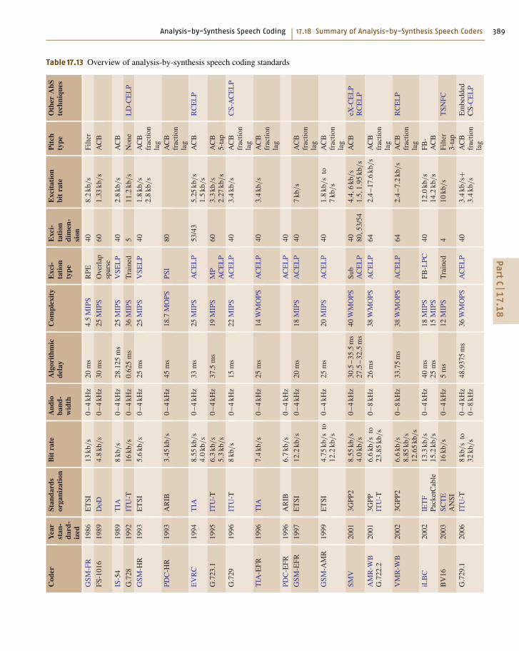
Analysis-by-Synthesis Speech Coding 17.18 Summary of Analysis-by-Synthesis Speech Coders 389
Table 17.13 Overview of analysis-by-synthesis speech coding standardsC
oder
Yea
rst
an-
dard
-iz
ed
Stan
dard
sor
gani
zati
onB
itra
teA
udio
band
-w
idth
Alg
orit
hmic
dela
yC
ompl
exit
yE
xci-
tati
onty
pe
Exc
i-ta
tion
dim
en-
sion
Exc
itat
ion
bit
rate
Pit
chty
peO
ther
AbS
tech
niqu
es
GSM
-FR
1986
ET
SI13
kb/s
0–
4kH
z20
ms
4.5
MIP
SR
PE40
8.2
kb/s
Filte
r
FS-1
016
1989
DoD
4.8
kb/s
0–
4kH
z30
ms
25M
IPS
Ove
rlap
spar
se60
1.33
kb/s
AC
B
IS-5
419
89T
IA8
kb/s
0–
4kH
z28
.125
ms
25M
IPS
VSE
LP
402.
8kb
/s
AC
B
G.7
2819
92IT
U-T
16kb
/s
0–
4kH
z0.
625
ms
36M
IPS
Tra
ined
511
.2kb
/s
Non
eL
D-C
EL
P
GSM
-HR
1993
ET
SI5.
6kb
/s
0–
4kH
z25
ms
25M
IPS
VSE
LP
401.
8kb
/s
2.8
kb/s
AC
Bfr
actio
nla
gPD
C-H
R19
93A
RIB
3.45
kb/s
0–
4kH
z45
ms
18.7
MO
PSPS
I80
AC
Bfr
actio
nla
gE
VR
C19
94T
IA8.
55kb
/s
4.0
kb/s
0–
4kH
z33
ms
25M
IPS
AC
EL
P53
/43
5.25
kb/s
1.5
kb/s
AC
BR
CE
LP
G.7
23.1
1995
ITU
-T6.
3kb
/s
5.3
kb/s
0–
4kH
z37
.5m
s19
MIP
SM
PA
CE
LP
603.
3kb
/s
2.27
kb/s
AC
B5-
tap
G.7
2919
96IT
U-T
8kb
/s
0–
4kH
z15
ms
22M
IPS
AC
EL
P40
3.4
kb/s
AC
Bfr
actio
nla
g
CS-
AC
EL
P
TIA
-EFR
1996
TIA
7.4
kb/s
0–
4kH
z25
ms
14W
MO
PSA
CE
LP
403.
4kb
/s
AC
Bfr
actio
nla
gPD
C-E
FR19
96A
RIB
6.7
kb/s
0–
4kH
zA
CE
LP
40
GSM
-EFR
1997
ET
SI12
.2kb
/s
0–
4kH
z20
ms
18M
IPS
AC
EL
P40
7kb
/s
AC
Bfr
actio
nla
gG
SM-A
MR
1999
ET
SI4.
75kb
/s
to12
.2kb
/s
0–
4kH
z25
ms
20M
IPS
AC
EL
P40
1.8
kb/s
to7
kb/s
AC
Bfr
actio
nla
gSM
V20
013G
PP2
8.55
kb/s
4.0
kb/s
0–
4kH
z30
.5–
35.5
ms
27.5
–32
.5m
s40
WM
OPS
Sub
AC
EL
P40 80
,53/
544.
4,6
kb/s
1.5,
1.95
kb/s
AC
BeX
-CE
LP
RC
EL
P
AM
R-W
BG
.722
.220
013G
PPIT
U-T
6.6
kb/s
to23
.85
kb/s
0–
8kH
z26
ms
38W
MO
PSA
CE
LP
642.
4–
17.6
kb/s
AC
Bfr
actio
nla
gV
MR
-WB
2002
3GPP
26.
6kb
/s
8.85
kb/s
12.6
5kb
/s
0–
8kH
z33
.75
ms
38W
MO
PSA
CE
LP
642.
4–
7.2
kb/s
AC
Bfr
actio
nla
g
RC
EL
P
iLB
C20
02IE
TF
Pack
etC
able
13.3
kb/s
15.2
kb/s
0–
4kH
z40
ms
25m
s18
MIP
S15
MIP
SFB
-LPC
4012
.0kb
/s
14.2
kb/s
FB-
AC
BB
V16
2003
SCT
EA
NSI
16kb
/s
0–
4kH
z5
ms
12M
IPS
Tra
ined
410
kb/s
Filte
r3-
tap
TSN
FC
G.7
29.1
2006
ITU
-T8
kb/s
to32
kb/s
0–
4kH
z0
–8
kHz
48.9
375
ms
36W
MO
PSA
CE
LP
403.
4kb
/s+
3.4
kb/s
AC
Bfr
actio
nla
g
Em
bedd
edC
S-C
EL
P
PartC
17.1
8
390 Part C Speech Coding
17.19 Conclusion
The analysis-by-synthesis method for coding the ex-citation signal of linear predictive coders has beenthe most important driving force behind the relent-less reduction of the bit-rate for high-quality speechcoding in the last two decades. Almost all speech cod-ing standards established after 1989 are based on it.This chapter gives a tutorial on analysis-by-synthesisspeech coding techniques in general and describesmany variations of the analysis-by-synthesis excitation
coding paradigm in particular. Due to space limita-tion, the description concentrates on dominant typesof analysis-by-synthesis excitation coding techniques asexemplified by various speech coding standards, withthe relationship between them discussed in the contextof a family tree. It is hoped that, after reading this chap-ter, the reader will have a good understanding of thedominant types of analysis-by-synthesis speech codingtechniques.
References
17.1 R.V. Cox: Speech coding standards. In: Speech Cod-ing and Synthesis, ed. by W.B. Kleijn, K.K. Paliwal(Elsevier Science, Amsterdam 1995)
17.2 B.S. Atal, J.R. Remde: A new model of LPC excitationfor producing natural-sounding speech at low bitrates, Proc. IEEE Int. Conf. Acoust. Speech SignalProcess. (1982) pp. 614–617
17.3 B.S. Atal, M.R. Schroeder: Stochastic coding ofspeech signals at very low bit rates, Proc. IEEE Int.Conf. Commun. (1984) p. 48.1
17.4 M.R. Schroeder, B.S. Atal: Code-excited linear pre-diction (CELP): high quality speech at very low bitrates, Proc. IEEE Int. Conf. Acoust. Speech SignalProcess. (1985) pp. 937–940
17.5 J.-H. Chen: A robust low-delay CELP speech coderat 16 kbit/s, Proc. IEEE Global Commun. Conf. (1989)pp. 1237–1241
17.6 J.-H. Chen, R.V. Cox, Y.-C. Lin, N.S. Jayant,M.J. Melchner: A low-delay CELP coder for the CCITT16 kb/s speech coding standard, IEEE J. Sel. AreasCommun. 10(5), 830–849 (1992)
17.7 R. Salami, C. Laflamme, J.-P. Adoul, A. Kataoka,S. Hayashi, T. Moriya, C. Lamblin, D. Massaloux,S. Proust, P. Kroon, Y. Shoham: Design and de-scription of CS-ACELP: a toll quality 8 kb/s speechcoder, IEEE Trans. Speech Audio Process. 6(2), 116–130 (1998)
17.8 J. Thyssen, Y. Gao, A. Benyassine, E. Shlomot,C. Murgia, H.-Y. Su, K. Mano, Y. Hiwasaki, H. Ehara,K. Yasunaga, C. Lamblin, B. Kovesi, J. Stegmann,H.-G. Kang: A candidate for the ITU-T 4 kbit/sspeech coding standard, Proc. IEEE Int. Conf.Acoust. Speech Signal Process. (2001) pp. 681–684
17.9 A. McCree, J. Stachurski, T. Unno, E. Ertan, E. Pak-soy, R. Viswanathan, A. Heikkinen, A. Ramo,S. Himanen, P. Blocher, O. Dressler: A 4 kb/s hybridMELP/CELP speech coding candidate for ITU stan-dardization, Proc. IEEE Int. Conf. Acoust. SpeechSignal Process. (2002) pp. 629–632
17.10 P. Kroon, W.B. Kleijn: Linear-prediction basedanalysis-by-synthesis coding. In: Speech Codingand Synthesis, ed. by W.B. Kleijn, K.K. Paliwal(Elsevier Science, Amsterdam 1995)
17.11 M. Halle, K.N. Stevens: Analysis by synthesis, Proc.Sem. Speech Compression and Process., Vol. II, ed.by W. Wathen-Dunn, L.E. Woods (1959), AFCRC-TR-59-198, Paper D7
17.12 C.G. Bell, H. Fujisaki, J.M. Heinz, K.N. Stevens,A.S. House: Reduction of speech spectra byanalysis-by-synthesis techniques, J. Acoust. Soc.Am. 33(12), 1725–1736 (1961)
17.13 N.S. Jayant, P. Noll: Digital Coding of Waveforms(Prentice Hall, Englewood Cliffs 1984)
17.14 L.R. Rabiner, R.W. Schafer: Digital Processing ofSpeech Signals (Prentice Hall, Englewood Cliffs1978)
17.15 W.B. Kleijn, R.P. Ramachandran, P. Kroon: Gen-eralized analysis-by-synthesis coding and itsapplication to pitch prediction, Proc. IEEE Int. Conf.Acoust. Speech Signal Process. (1992) pp. I–337–I–340
17.16 B.S. Atal, M.R. Schroeder: Predictive coding ofspeech signals and subjective error criteria, IEEETrans. Acoust. Speech Signal Process. 3, 247–254(1979)
17.17 I.A. Gerson, M.A. Jasiuk: Vector sum excited linearprediction (VSELP) speech coding at 8 kbps, Proc.IEEE Int. Conf. Acoust. Speech Signal Process. (1990)pp. 461–464
17.18 P. Vary, K. Hellwig, R. Hofmann, R.J. Sluyter, C. Ga-land, M. Rosso: Speech codec for the Europeanmobile radio system, Proc. IEEE Int. Conf. Acoust.Speech Signal Process. (1988) pp. 227–230
17.19 S. Singhal, B. Atal: Improving performance ofmulti-pulse LPC coders at low bit rates, Proc. IEEEInt. Conf. Acoust. Speech Signal Process. (1984)pp. 9–12
17.20 J.P. Campbell Jr., V.C. Welch, T.E. Tremain: Anexpandable error-protected 4800 bps CELP coder
PartC
17

Analysis-by-Synthesis Speech Coding References 391
(U.S. Federal standard 4800 bps voice coder), Proc.IEEE Int. Conf. Acoust. Speech Signal Process. (1989)pp. 735–738
17.21 I.A. Gerson, M.A. Jasiuk: A 5600 bps VSELP speechcoder candidate for half-rate GSM, Proc. 1993 IEEEWorkshop Speech Coding for Telecommunications(1993) pp. 43–44
17.22 T. Ohya, H. Suda, T. Miki: 5.6 kbits/s PSI-CELP ofthe half-rate PDC speech coding standard, Proc.1994 IEEE Vehicular Technol. Conf. (1994) pp. 1680–1684
17.23 J.-P. Adoul, P. Mabilleau, M. Delprat, S. Morisette:Fast CELP coding based on algebraic codes, Proc.IEEE Int. Conf. Acoust. Speech Signal Process. (1987)pp. 1957–1960
17.24 C. Laflamme, J.-P. Adoul, H.Y. Su, S. Morisette: Onreducing computational complexity of codebooksearch in CELP coder through the use of algebraiccodes, Proc. IEEE Int. Conf. Acoust. Speech SignalProcess. (1990) pp. 177–180
17.25 ITU-T: G.723.1: Dual rate speech coder for multi-media communications transmitting at 5.3 and 6.3kbit/s (1996)
17.26 ANSI/TIA-127-A-2004: Enhanced variable rate codecspeech service option 3 for wideband spread spec-trum digital systems (2004) (ANSI/TIA-127-A-2004)
17.27 Y. Gao, E. Shlomot, A. Benyassine, J. Thyssen, H. Su:The SMV algorithm selected by TIA and 3GPP2 forCDMA applications, Proc. IEEE Int. Conf. Acoust.Speech Signal Process. (2001) pp. 709–712
17.28 3GPP2 C.S0052-0 V1.0: Source-controlled variable-rate multimode wideband speech codec (VMR-WB)service option 62 for spread spectrum systems,(June 11 2004)
17.29 J.-H. Chen, J. Thyssen: BroadVoice 16: A PacketCablespeech coding standard for cable telephony, Proc.40th Asilomar Conf. Signals Systems and Computers(2006)
17.30 J.-H. Chen, J. Thyssen: The BroadVoice speech cod-ing algorithm, Proc. IEEE Int. Conf. Acoust. SpeechSignal Process., Vol. 4 (2007) p. IV-549-IV-552
17.31 S.V. Andersen, W.B. Kleijn, R. Hagen, J. Linden,M.N. Murthi, J. Skoglund: iLBC - a linear predictivecoder with robustness to packet losses, Proc. IEEEWorkshop Speech Coding (2002) pp. 23–25
17.32 S.V. Andersen, A. Duric, H. Astrom, R. Hagen,W.B. Kleijn, J. Linden: Internet low bit rate codec(iLBC), IETF RFC 3951 (2004)
17.33 American National Standard: BV16 speech codecspecification for voice over ip applications in cabletelephony, ANSI/SCTE 24-21 2006 (2006)
17.34 B.S. Atal, S.L. Hanauer: Speech analysis and syn-thesis by linear prediction, J. Acoust. Soc. Am. 50,637–655 (1971)
17.35 E.F. Deprettere, P. Kroon: Regular excitation reduc-tion for effective and efficient LP-coding of speech,Proc. IEEE Int. Conf. Acoust. Speech Signal Process.(1985) pp. 965–968
17.36 W.B. Kleijn, D.J. Krasinski, R.H. Ketchum: Improvedspeech quality and efficient vector quantizationin SELP, Proc. IEEE Int. Conf. Acoust. Speech SignalProcess. (1988) pp. 155–158
17.37 I.M. Trancoso, B.S. Atal: Efficient procedures forfinding the optimum innovation in stochasticcoders, Proc. IEEE Int. Conf. Acoust. Speech SignalProcess. (1986) pp. 2375–2378
17.38 G. Davidson, A. Gersho: Complexity reductionmethods for vector excitaiton coding, Proc. IEEEInt. Conf. Acoust. Speech Signal Process. (1986)pp. 3055–3058
17.39 D. Lin: Speech coding using pseudo-stochasticblock codes, Proc. IEEE Int. Conf. Acoust. SpeechSignal Process. (1987) pp. 1354–1357
17.40 I.A. Gerson, M.A. Jasiuk: Vector sum excitedlinear prediction (VSELP), Proc. 1989 IEEE Work-shop Speech Coding for Telecommunications (1989)pp. 66–68
17.41 P. Kroon, B.S. Atal: Pitch predictors with hightemporal resolution, Proc. IEEE Int. Conf. Acoust.Speech Signal Process. (1990) pp. 661–664
17.42 J.S. Marques, I.M. Trancoso, J.M. Tribolet,L.B. Almeida: Improved pitch prediction with frac-tional delays in CELP coding, Proc. IEEE Int. Conf.Acoust. Speech Signal Process. (1990) pp. 665–668
17.43 J.H. Chen, M.S. Rauchwerk: An 8 kb/s low-delayCELP speech coder, Proc. IEEE Global Commun. Conf.(1991) pp. 1894–1898
17.44 S. Miki, K. Mano, H. Ohmuro, T. Moriya: Pitch syn-chronous innovation CELP (PSI-CELP), Proc. 1993Eurospeech Conf. (1993) pp. 261–264
17.45 T. Moriya: Two-channel conjugate vector quanti-zation for noisy channel speech coding, IEEE J. Sel.Areas Commun. 10(5), 866–874 (1992)
17.46 ITU-T: G.729: coding of speech at 8 kbit/s usingconjugate-structure algebraic-code-excited linearprediction (CS-ACELP) (1996)
17.47 J.-P. Adoul, C. Lamblin: A comparison of some al-gebraic structures for CELP coding of speech, Proc.IEEE Int. Conf. Acoust. Speech Signal Process. (1987)pp. 1953–1956
17.48 R.A. Salami: Binary code excited linear prediction(BCELP): a new approach to CELP coding of speechwithout the codebooks, IEEE Electron. Lett. 25(6),401–403 (1989)
17.49 A. Le Guyader, D. Massaloux, J.P. Petit: Robustand fast code-excited linear predictive coding ofspeech signals, Proc. IEEE Int. Conf. Acoust. SpeechSignal Process. (1989) pp. 120–122
17.50 J.-P. Adoul, C. Lamblin, A. Leguyader: Basebandspeech coding at 2400 BPS using spherical vec-tor quantization, IEEE Int. Conf. Commun. (1984)pp. 1.12.1–1.12.4
17.51 C. Laflamme, J.-P. Adoul, S. Morisette: A real time4.8 Kbits/sec CELP on a single DSP chip (TMS320C25),IEEE Workshop Speech Coding for Telecommun.(1989) pp. 35–36
PartC
17
392 Part C Speech Coding
17.52 R.A. Salami, D.G. Appleby: A new approach to lowbit rate speech coding with low complexity us-ing binary pulse excitation (BPE), IEEE WorkshopSpeech Coding for Telecommun. (1989) pp. 63–65
17.53 C. Laflamme, J.-P. Adoul, R. Salami, S. Morisette,P. Mabilleau: 16 kbps wideband speech codingtechnique based on algebraic CELP, Proc. IEEE Int.Conf. Acoust. Speech Signal Process. (1991) pp. 13–16
17.54 R. Salami, C. Laflamme, J.-P. Adoul, D. Massaloux:A toll quality 8 kb/s speech codec for the personalcommunications system (PCS), IEEE Trans. VehicularTechnol. 43(3), 808–816 (1994)
17.55 K. Järvinen, J. Vaino, P. Kapanen, T. Honkanen,P. Haavisto, R. Salami, C. Laflamme, J.-P. Adoul:GSM enhanced full rate speech codec, Proc. IEEE Int.Conf. Acoust. Speech Signal Process. (1997) pp. 771–774
17.56 ETSI EN 300 726 V8.0.1: Digital cellular telecommu-nications systems (Phase 2+); enhanced full rate(EFR) speech transcoding; (GSM 06.60 version 8.0.1Release 1999) (2000)
17.57 3GPP TS 26.190 V6.1.1: 3rd generation partnershipproject; technical specification group services andsystem aspects; speech codec speech processingfunctions; adaptive multi-rate - wideband (AMR-WB) speech codec; transcoding functions (release6) (2005)
17.58 R. Salami, C. Laflamme, J.P. Adoul, A. Kataoka,S. Hayashi, T. Moriya, C. Lamblin, D. Massaloux,S. Proust, P. Kroon, Y. Shoham: Design and de-scription of CS-ACELP: a toll quality 8 kb/s speechcoder, IEEE Trans. Speech Audio Process. 6(2), 116–130 (1998)
17.59 ITU-T: G.729 Annex A: reduced complexity 8 kbit/sCS-ACELP speech codec (1996)
17.60 R. Salami, C. Laflamme, B. Bessette, J.P. Adoul: ITU-T G.729 Annex A: reduced complexity 8 kb/s CS-ACELP Codec for simultaneous vocie and data, IEEECommun. Mag. 35, 56–63 (1997)
17.61 ITU-T: G.722.2: wideband coding of speech ataround 16 kbit/s using adaptive multi-rate wide-band (AMR-WB) (2002)
17.62 3GPP TS 26.090 V6.0.0: 3rd generation partnershipproject; technical specification group services andsystem aspects; mandatory speech codec speechprocessing functions; adaptive multi-rate (AMR)speech codec; transcoding functions (release 6)(2004)
17.63 ANSI/TIA/EIA-136-410-99: TDMA cellular PCS - ra-dio interface enhanced full-rate voice codec(ANSI/TIA/EIA-136-410-99) (R2003) (1999)
17.64 3GPP2 C.S0030-0 V1.0: Selectable mode vocoderservice option for wideband spread spectrum com-munication systems, (June 15 2001)
17.65 ISO/IEC 14496-3 FCD, ISO/JTC 1/SC 29 N2203CELP: Infor-mation technology - coding of audiovisual objects,Part 3: audio, subpart 3: CELP, (May 13 1998)
17.66 A. Kataoka, T. Moriya, S. Hayashi: An 8-kbit/sspeech coder based on conjugate structure CELP,Proc. IEEE Int. Conf. Acoust. Speech Signal Process.(1993) pp. II–592–II–595
17.67 T. Moriya, H. Suda: An 8 kbit/s transform coder fornoisy channels, Proc. IEEE Int. Conf. Acoust. SpeechSignal Process. (1989) pp. 196–199
17.68 A. Kataoka, T. Moriya, S. Hayashi: An 8-kb/s con-jugate structure CELP (CS-CELP) speech coder, IEEETrans. Speech Audio Process. 4(6), 401–411 (1996)
17.69 W.B. Kleijn, P. Kroon, L. Cellario, D. Sereno: A 5.85kb/s CELP algorithm for cellular applications, Proc.IEEE Int. Conf. Acoust. Speech Signal Process. (1993)pp. II–596–II–599
17.70 W.B. Kleijn, R.P. Ramachandran, P. Kroon: In-terpolation of the pitch-predictor parameters inanalysis-by-synthesis speech coders, IEEE Trans.Speech Audio Process. 2(1), 42–53 (1994)
17.71 Y. Gao, A. Benyassine, J. Thyssen, H. Su, E. Shlomot:A speech coding paradigm, Proc. IEEE Int. Conf.Acoust. Speech Signal Process. (2001) pp. 689–692
17.72 J.-H. Chen: Novel codec structures for noise feed-back coding of speech, Proc. IEEE Int. Conf. Acoust.Speech Signal Process. (2006) pp. I.681–I.684
17.73 J.D. Makhoul, M. Berouti: Adaptive noise spectralshaping and entropy coding in predictive coding ofspeech, IEEE Trans. Acoust. Speech Signal Process.27, 63–73 (1979)
17.74 J. Thyssen, J.-H. Chen: Efficient VQ techniques andgeneral noise shaping for noise feedback coding,Proc. Interspeech 2006 ICSLP (2006) pp. 221–224
17.75 PacketCable 2.0 codec and media specification,PKT-SP-CODEC-MEDIA-I02-061013 (2006)
17.76 ITU-T: G.729.1: G.729 based embedded variable bit-rate coder: An 8-32 kbit/s scalable wideband coderbitstrean interoperable with G.729 (2006)
17.77 ITU-T: G.726: 40, 32, 24, 16 kbit/s adaptive differ-ential pulse code modulation (ADPCM) (1990)
17.78 ITU-T: G.722: 7 kHz audio-coding within 64 kbit/s(1988)
PartC
17