Embed Size (px)
Citation preview

v2000.05 Guide to HDL Coding Styles for Synthesis
3Coding Styles for Logic Building Blocks 3
This chapter shows different coding styles for logic building blockssuch as decoders and priority encoders. A typical coding style and arecommended coding style are presented for each building block.
The examples in this chapter are parameterizable: They can bemodified for any bit-width. Therefore, they may appear more complexthan examples written for a specific bit-width.
Decoder
Example 3-1 and Example 3-2 show Verilog and VHDL with afrequently used coding style for decoders. The input is used as anindex to the output in these examples.
/ 3-1HOME CONTENTS
v2000.05 Guide to HDL Coding Styles for Synthesis
Example 3-1 Verilog for Decoder Using Indexingmodule decoder_index (in1, out1);parameter N = 8;parameter log2N = 3;input [log2N-1:0] in1;output [N-1:0] out1;reg [N-1:0] out1;always @(in1)begin
out1 = 0;out1[in1] = 1’b1;
endendmodule
Example 3-2 VHDL for Decoder Using Indexinglibrary IEEE;use IEEE.std_logic_1164.all;use IEEE.std_logic_unsigned.all;
entity decoder38_index isgeneric (N: natural := 8; log2N: natural := 3);port (in1: in std_logic_vector(log2N-1 downto 0); out1: out std_logic_vector(N-1 downto 0));end decoder38_index;
architecture one of decoder38_index issignal in1_int: natural range 0 to N-1;begin
in1_int <= CONV_INTEGER(in1);process(in1_int)begin
out1 <= (others => ’0’);out1(in1_int) <= ’1’;
end process;end one;
Example 3-3 and Example 3-4 show an alternative coding style fordecoders, using a for loop.
/ 3-2HOME CONTENTS

v2000.05 Guide to HDL Coding Styles for Synthesis
Example 3-3 Verilog for Decoder Using Loopmodule decoder38_loop (in1, out1);parameter N = 8;parameter log2N = 3;input [log2N-1:0] in1;output [N-1:0] out1;reg [N-1:0] out1;integer i;
always @(in1)begin
for(i=0;i<N;i=i+1)out1[i] = (in1 == i);
endendmodule
Example 3-4 VHDL for Decoder Using Looplibrary IEEE;use IEEE.std_logic_1164.all;use IEEE.std_logic_unsigned.all;
entity decoder_loop isgeneric (N: natural := 8; log2N: natural := 3);port (in1: in std_logic_vector(log2N-1 downto 0); out1: out std_logic_vector(N-1 downto 0));end decoder_loop;
architecture one of decoder_loop issignal in1_int: natural range 0 to N-1;begin
in1_int <= CONV_INTEGER(in1);process(in1_int)begin
out1 <= (others => ’0’);for i in 0 to N-1 loop
if (in1_int = i) thenout1(i) <= ’1’;
end if;end loop;
end process;end one;
/ 3-3HOME CONTENTS

v2000.05 Guide to HDL Coding Styles for Synthesis
Table 3-1 and Figure 3-1 show timing results for different-sizedecoders, using the decoder coding styles described in the precedingexamples.
Figure 3-1 Decoder Timing Results Versus Address Width
Table 3-2 and Figure 3-2 show area results for the decoder codingstyles described in the preceding examples.
Table 3-1 Timing Results for Decoder Coding Styles
Input Address Width 3 4 5 6 7 8
Index 0.64 0.86 1.33 1.52 2.11 2.37
Loop 0.64 0.86 1.33 1.57 1.98 2.10
Table 3-2 Area Results for Decoder Coding Styles
Input Address Width 3 4 5 6 7 8
Index 18 29 61 115 195 583
Loop 18 30 61 116 195 346
/ 3-4HOME CONTENTS

v2000.05 Guide to HDL Coding Styles for Synthesis
Figure 3-2 Decoder Area Versus Address Width
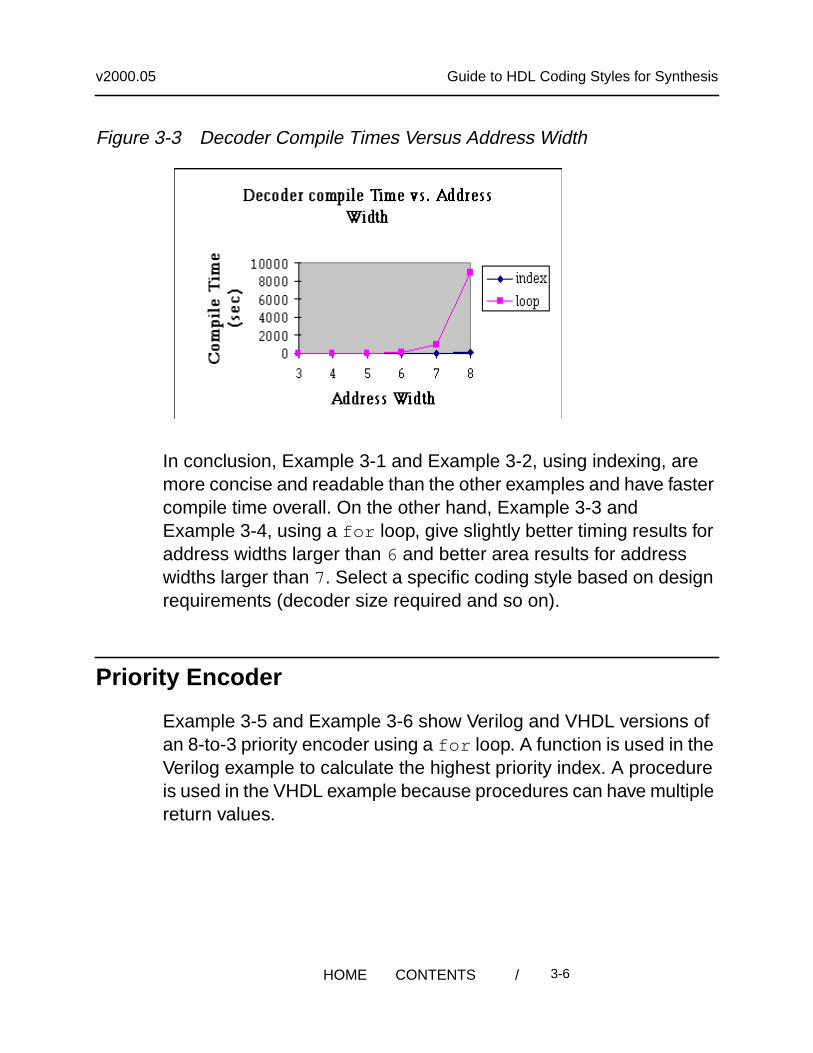
Table 3-3 and Figure 3-3 show compile time for the decoder codingstyles described previously.
Table 3-3 Compile Time (Seconds) for Decoder Coding Styles
Input Address Width 3 4 5 6 7 8
Index 2 3 11 18 58 132
Loop 16 13 42 163 946 9000
/ 3-5HOME CONTENTS
v2000.05 Guide to HDL Coding Styles for Synthesis
Figure 3-3 Decoder Compile Times Versus Address Width
In conclusion, Example 3-1 and Example 3-2, using indexing, aremore concise and readable than the other examples and have fastercompile time overall. On the other hand, Example 3-3 andExample 3-4, using a for loop, give slightly better timing results foraddress widths larger than 6 and better area results for addresswidths larger than 7. Select a specific coding style based on designrequirements (decoder size required and so on).
Priority Encoder
Example 3-5 and Example 3-6 show Verilog and VHDL versions ofan 8-to-3 priority encoder using a for loop. A function is used in theVerilog example to calculate the highest priority index. A procedureis used in the VHDL example because procedures can have multiplereturn values.
/ 3-6HOME CONTENTS

v2000.05 Guide to HDL Coding Styles for Synthesis
Example 3-5 Verilog for Priority Encoder Using Loop Starting With Lowest-Priority Bit
module priority_low_high (A, P, F);parameter N = 8;parameter log2N = 3;input [N-1:0] A; //Input Vectoroutput [log2N-1:0] P; // High Priority Indexoutput F; // Found a one?reg [log2N-1:0] P;reg F;
function [log2N:0] priority;input [N-1:0] A;reg F;integer I;begin
F = 1’b0;priority = {3’b0, F};for (I=0; I<N; I=I+1)
if (A[I])begin
F = 1’b1;priority = {I, F};// Override previous index
endendendfunction
always @(A)begin
{P, F} <= priority(A);endendmodule
Example 3-6 is the equivalent VHDL example. This example uses afunction, log2 , to calculate log base 2 and a procedure to find thehighest-priority index.
/ 3-7HOME CONTENTS

v2000.05 Guide to HDL Coding Styles for Synthesis
Example 3-6 VHDL for Priority Encoder Using Loop Starting With Lowest-Priority Bit
package pri_pack isfunction log2(A: natural) return natural;
end pri_pack;
package body pri_pack isfunction log2(A: natural) return natural isbegin
for I in 1 to 30 loop -- Works for up to 32 bit integersif (2**I > A) then
return(I-1);end if;
end loop;return(30);
end;end pri_pack;
library IEEE;use work.pri_pack.all;use IEEE.std_logic_1164.all;use IEEE.std_logic_arith.all;
entity priority_low_high isgeneric(N: natural := 3);port (A: in std_logic_vector(2**N - 1 downto 0); P: out std_logic_vector(N-1 downto 0); F: out std_logic);end priority_low_high;
architecture a of priority_low_high isprocedure priority(A: in std_logic_vector; -- Input Vector
P: out std_logic_vector; -- High Priority IndexF: out std_logic) isb -- Found a one?
constant WIDTH: NATURAL := A’length;constant LOG_WIDTH: NATURAL := log2(WIDTH);begin
P := CONV_STD_LOGIC_VECTOR(CONV_UNSIGNED(0, LOG_WIDTH),LOG_WIDTH); -- Set output default
F := ’0’;for I in 0 to WIDTH-1 loop
if(A(I) = ’1’) then-- If found a ’1’P := CONV_STD_LOGIC_VECTOR(CONV_UNSIGNED(I, LOG_WIDTH),
LOG_WIDTH); -- Override previous indexF := ’1’;
end if;end loop;
/ 3-8HOME CONTENTS

v2000.05 Guide to HDL Coding Styles for Synthesis
end priority;
beginprocess(A)variable PV: std_logic_vector(N-1 downto 0);variable FV: std_logic;
beginpriority(A, PV, FV);P <= PV;F <= FV;
end process;end a;
Example 3-4 shows the chain structure implied by the HDL inExample 3-5 and Example 3-6.
Figure 3-4 Chain Structure for Priority Encoder
1
0
010 011 100
101110
111
P [2:0]
00
A [1]2
A [3]2A [2]
2
A [4]2
A [5] 2A [6]
2
2A [7]
1
0
A [0]A [1]
2 22
22
22
21
11
11
11
A [2]A [3]
A [4]A [5]
A [6]A [7]
F
/ 3-9HOME CONTENTS

v2000.05 Guide to HDL Coding Styles for Synthesis
Example 3-5 and Example 3-6 can be modified to create a treestructure. Tree structures generally result in better performance. Onlythe VHDL tree structure is shown in Example 3-7.
Using recursion in VHDL gives you the ability to create a priorityencoder in a tree structure. Example 3-7 uses recursive procedurecalls to generate a tree structure for a priority encoder.
/ 3-10HOME CONTENTS

v2000.05 Guide to HDL Coding Styles for Synthesis
Example 3-7 VHDL for Priority Encoder Treepackage pri_pack2 is
function log2(A: integer) return integer;function max(A,B: integer) return integer;
end pri_pack2;
package body pri_pack2 isfunction max(A,B: integer) return integer isbegin
if(A<B) thenreturn(B);
elsereturn(A);
end if;end;
function log2(A: integer) return integer isbegin
for I in 1 to 30 loop-- Works for up to 32 bit integersif(2**I > A) then
return(I-1);end if;
end loop;return(30);
end;end pri_pack2;
library IEEE;use IEEE.std_logic_1164.all;use work.pri_pack2.all;
entity priority_tree isport (A: in std_logic_vector(2**N - 1 downto 0);
P: out std_logic_vector(N-1 downto 0);F: out std_logic);
end priority_tree;
architecture a of priority_tree is
procedure priority(A: in std_logic_vector; -- Input VectorP: out std_logic_vector; -- High Priority IndexF: out std_logic) is -- Found a one?
constant WIDTH: INTEGER := A’length;constant LOG_WIDTH: INTEGER := log2(WIDTH);variable AT: std_logic_vector(WIDTH-1 downto 0);variable F1, F0: std_logic;variable PRET: std_logic_vector(LOG_WIDTH-1 downto 0);variable P1, P0, PT:std_logic_vector(max(LOG_WIDTH-2,0) downto 0);
/ 3-11HOME CONTENTS

v2000.05 Guide to HDL Coding Styles for Synthesis
beginAT := A; -- Normalize array indices
-- Handle Degenerate case of single input
if(WIDTH = 1) thenF := AT(0);
-- This is the bottom of the recursion: a 2-bit priority encoder
elsif(WIDTH = 2) thenPRET(0) := AT(0);F := AT(1) or AT(0);
-- Recurse on the two halves, and compute combined result
elsepriority(AT(WIDTH-1 downto WIDTH/2), P1, F1);priority(AT(WIDTH/2-1 downto 0), P0, F0);
F := F1 or F0;
if(F1 = ’1’) then --If the first half had a ’1’, use its index.PT := P1;
elsePT := P0; -- Otherwise, use the second half’s index.
end if;PRET := F1 & PT; -- The result MSB is ’1’ if the first half
-- had a ’1’.end if;P := PRET;
end priority;
beginprocess(A)variable PV: std_logic_vector(N-1 downto 0);variable FV: std_logic;begin
priority(A, PV, FV);P <= PV;F <= FV;
end process;end a;
/ 3-12HOME CONTENTS
v2000.05 Guide to HDL Coding Styles for Synthesis
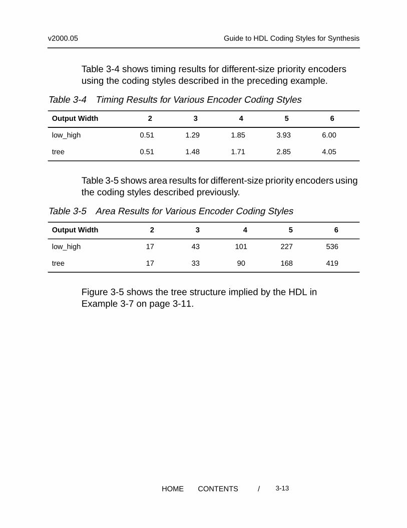
Table 3-4 shows timing results for different-size priority encodersusing the coding styles described in the preceding example.
Table 3-5 shows area results for different-size priority encoders usingthe coding styles described previously.
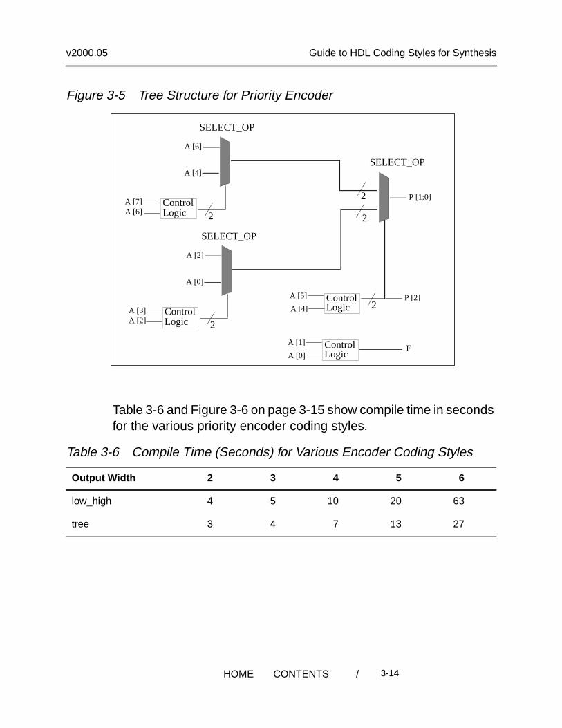
Figure 3-5 shows the tree structure implied by the HDL inExample 3-7 on page 3-11.
Table 3-4 Timing Results for Various Encoder Coding Styles
Output Width 2 3 4 5 6
low_high 0.51 1.29 1.85 3.93 6.00
tree 0.51 1.48 1.71 2.85 4.05
Table 3-5 Area Results for Various Encoder Coding Styles
Output Width 2 3 4 5 6
low_high 17 43 101 227 536
tree 17 33 90 168 419
/ 3-13HOME CONTENTS
v2000.05 Guide to HDL Coding Styles for Synthesis
Figure 3-5 Tree Structure for Priority Encoder
Table 3-6 and Figure 3-6 on page 3-15 show compile time in secondsfor the various priority encoder coding styles.
Table 3-6 Compile Time (Seconds) for Various Encoder Coding Styles
Output Width 2 3 4 5 6
low_high 4 5 10 20 63
tree 3 4 7 13 27
A [2]
A [0]
SELECT_OP
ControlLogic 2
A [3]A [2]
A [6]
A [4]
SELECT_OP
ControlLogic 2
A [7]A [6]
SELECT_OP
2
2 P [1:0]
LogicControlA [5]
A [4] 2P [2]
LogicControlA [1]
A [0]F
/ 3-14HOME CONTENTS

v2000.05 Guide to HDL Coding Styles for Synthesis
Figure 3-6 Priority Encoder Compile Time Versus Output Width
In conclusion, Example 3-5 on page 3-7 and Example 3-6 on page3-8, using loops to override the previous index, are more concise andreadable. But the tree version in Example 3-7 on page 3-11 is betterwith respect to timing, area, and compile time. In addition, the QORdifference between the two versions increases as the size of thepriority encoder gets larger. For designs that are pushingperformance, the tree version is the recommended coding style.
Reduction XOR
Reduction functions, especially reduction XORs, are frequently usedin designs. Example 3-8 and Example 3-9 show Verilog and VHDLfor a reduction XORimplemented in a chain structure. Chain structuresare common for reduction functions.
/ 3-15HOME CONTENTS
v2000.05 Guide to HDL Coding Styles for Synthesis
Example 3-8 Verilog for Reduction XOR Chainmodule XOR_reduce (data_in, data_out);parameter N = 5;input [N-1:0] data_in;output data_out;reg data_out;
function XOR_reduce_func;input [N-1:0] data;integer I;begin
XOR_reduce_func = 0;for (I = N-1; I >= 0; I=I-1)
XOR_reduce_func = XOR_reduce_func ^ data[I];endendfunction
always @(data_in)begin
data_out <= XOR_reduce_func(data_in);endendmodule
/ 3-16HOME CONTENTS

v2000.05 Guide to HDL Coding Styles for Synthesis
Example 3-9 VHDL for Reduction XOR Chainlibrary IEEE;use IEEE.std_logic_1164.all;
entity XOR_reduce isgeneric (N: natural := 5);port (data_in: in std_logic_vector(N-1 downto 0);
data_out: out std_logic);end XOR_reduce;
architecture one of XOR_reduce isfunction XOR_reduce_func(data:std_logic_vector)return std_logic isvariable result : std_logic;begin
result := ’0’;for I in data’RANGE loop
result := result XOR data(I);end loop;return result;
end;
begindata_out <= XOR_reduce_func(data_in);
end one;
Figure 3-7 shows the chain structure implied by the HDL inExample 3-8 and Example 3-9.
Figure 3-7 Chain Structure for Reduction XOR
Example 3-10 on page 3-18 and Example 3-11 on page 3-20 showVerilog and VHDL, respectively, for the reduction XOR implementedin a tree structure.
data_in[4]
data_in[3]
data_in[2]
data_in[1]
data_in[0]
0
data_out
/ 3-17HOME CONTENTS

v2000.05 Guide to HDL Coding Styles for Synthesis
Example 3-10 Verilog for XOR Treemodule XOR_tree(data_in, data_out);parameter N = 5;parameter logN = 3;input[N-1:0] data_in;output data_out;reg data_out;
function even;input [31:0] num;begin
even = ~num[0];endendfunction
function XOR_tree_func;input [N-1:0] data;integer I, J, K, NUM;reg [N-1:0] temp, result;begin
temp[N-1:0] = data_in[N-1:0];NUM = N;for (K=logN-1; K>=0; K=K-1)begin
J = (NUM+1)/2;J = J-1;if (even(NUM))
for (I=NUM-1; I>=0; I=I-2)begin
result[J] = temp[I] ^ temp[I-1];J = J-1;
endelsebegin
for (I=NUM-1; I>=1; I=I-2)begin
result[J] = temp[I] ^ temp[I-1];J = J-1;
endresult[0] = temp[0];
/ 3-18HOME CONTENTS
v2000.05 Guide to HDL Coding Styles for Synthesis
endtemp[N-1:0] = result[N-1:0];NUM = (NUM+1)/2;
endXOR_tree_func = result[0];
endendfunction
always @(data_in)begin
data_out <= XOR_tree_func(data_in);endendmodule
The VHDL version shown in Example 3-11 uses recursion to build atree.
/ 3-19HOME CONTENTS

v2000.05 Guide to HDL Coding Styles for Synthesis
Example 3-11 VHDL for XOR Treelibrary IEEE;use IEEE.std_logic_1164.all;
entity XOR_tree isgeneric (N: natural := 4);port (data_in: in std_logic_vector(N downto 0);
data_out: out std_logic);end XOR_tree;
architecture one of XOR_tree isfunction XOR_tree_func(data: std_logic_vector) return std_logic isvariable UPPER_TREE, LOWER_TREE: std_logic;variable MID, LEN: natural;variable result: std_logic;variable i_data: std_logic_vector(data’LENGTH-1 downto 0);begin
i_data := data;LEN := i_data’LENGTH;if LEN = 1 then
result := i_data(i_data’LEFT);elsif LEN = 2 then
result := i_data(i_data’LEFT) XOR i_data(i_data’RIGHT);else
MID := (LEN + 1)/2 + i_data’RIGHT;UPPER_TREE := XOR_tree_func(i_data(i_data’LEFT downto MID));LOWER_TREE := XOR_tree_func(i_data(MID-1 downto i_data’RIGHT));result := UPPER_TREE XOR LOWER_TREE;
end if;return result;
end;begin
data_out <= XOR_tree_func(data_in);end one;
Figure 3-8 shows the tree structure implied by the HDL inExample 3-10 and Example 3-11.
/ 3-20HOME CONTENTS

v2000.05 Guide to HDL Coding Styles for Synthesis
Figure 3-8 Tree Structure for Reduction XOR
In conclusion, Design Compiler can convert the XORchain structureto a tree structure during compile. However, it does not do so if thechain is used in a design that accesses intermediate points in thechain (outputs of gates along the chain). Therefore, it is best to startwith the tree structure. OR chains with intermediate points, on theother hand, are converted to trees.
Multiplexer
Example 3-12 on page 3-22 and Example 3-13 on page 3-23 show,respectively, Verilog and VHDL for multiplexer chains. The structureimplied by the HDL is a chain of multiplexing logic. This does notmean Design Compiler necessarily infers multiplexer cells for thislogic. For information on how to get Design Compiler to map tomultiplexer cells (especially large multiplexer cells) in the technologylibrary, see the HDL Compiler for Verilog Reference Manual.
data_in[4]data_in[3]
data_in[2]data_in[1]
data_in[0]data_out
/ 3-21HOME CONTENTS

v2000.05 Guide to HDL Coding Styles for Synthesis
Example 3-12 Verilog for Multiplexer Chainmodule mux_chain (sel, data_in, data_out);parameter N = 5;input [N-1:0] sel;input [N:0] data_in;output data_out;reg data_out;
function mux_chain_func;input [N-1:0] sel;input [N:0] data_in;reg [N-1:0] i_sel;reg [N:0] i_data;reg result;integer I;begin
i_sel = sel;i_data = data_in;mux_chain_func = i_data[N];for (I = N-1; I >= 0; I=I-1)
if (i_sel[I])mux_chain_func = i_data[I];
endendfunction
always @(sel or data_in)begin
data_out <= mux_chain_func(sel, data_in);endendmodule
/ 3-22HOME CONTENTS

v2000.05 Guide to HDL Coding Styles for Synthesis
Example 3-13 VHDL for Multiplexer Chainlibrary IEEE;use IEEE.std_logic_1164.all;
entity mux_chain isgeneric (N: natural := 5);port (sel: in std_logic_vector(N-1 downto 0);
data_in: in std_logic_vector(N downto 0);data_out: out std_logic);
end mux_chain;
architecture one of mux_chain isfunction mux_chain_func(sel, data: std_logic_vector)
return std_logic isvariable i_sel: std_logic_vector(sel’LENGTH-1 downto 0);variable i_data: std_logic_vector(data’LENGTH-1 downto 0);variable result: std_logic;begin
i_sel:= sel;i_data:= data;result:= i_data(i_data’LEFT);for I in i_sel’LENGTH - 1 downto 0 loop
if i_sel(I) = ’1’ thenresult := i_data(I);
end if;end loop;return result;
end;
begindata_out <= mux_chain_func(sel, data_in);
end one;
Figure 3-9 shows the structure implied by the HDL in Example 3-12and Example 3-13.
/ 3-23HOME CONTENTS

v2000.05 Guide to HDL Coding Styles for Synthesis
Figure 3-9 Structure Implied by Multiplexer Chain Example
Example 3-14 and Example 3-15 show Verilog and VHDL that implythe same multiplexing functionality shown in Example 3-12 andExample 3-13 but in a tree structure rather than a chain structure.
SELECT_OP
SELECT_OPSELECT_OP
SELECT_OP
sel[0]
sel[2]sel[3]
2sel[4]2
data_in[4]
data_in[5]
data_in[3]data_in[2]
2
data_in[1]
sel[1]2
SELECT_OPdata_in[0]
2
data_out
/ 3-24HOME CONTENTS

v2000.05 Guide to HDL Coding Styles for Synthesis
Example 3-14 Verilog for Multiplexer Treemodule mux_tree(sel, data_in, data_out);parameter N = 8;parameter log2N = 3;input [N-2:0] sel;input [N-1:0] data_in;output data_out;reg data_out;
function even;input [31:0] num;begin
even = ~num[0];endendfunction
function mux_2_1;input sel;input [1:0]data;
beginif (sel)
mux_2_1 = data[0];else
mux_2_1 = data[1];endendfunction
function mux_tree_func;input [N-2:0] sel;input [N-1:0] data_in;reg [N-1:0] i_sel, temp_sel;reg [N-1:0] i_data, result;integer I, J, K, S;integer TREE_DEPTH;integer SEL_LEN, DATA_LEN;
begini_data[N-1:0] = data_in[N-1:0];i_sel[N-2:0] = sel[N-2:0];i_sel[N-1] = 1’b0;DATA_LEN = N;SEL_LEN = N-1;for (TREE_DEPTH=log2N-1; TREE_DEPTH>=0;
TREE_DEPTH=TREE_DEPTH-1)begin
SEL_LEN = (DATA_LEN+1)/2;S = SEL_LEN-1;
/ 3-25HOME CONTENTS

v2000.05 Guide to HDL Coding Styles for Synthesis
J = (DATA_LEN+1)/2;J = J-1;if (even(DATA_LEN))for (I=DATA_LEN-1; I>=1; I=I-2)begin
result[J] = mux_2_1(i_sel[I-1], {i_data[I],i_data[I-1]});
temp_sel[S] = |{i_sel[I-1], i_sel[I]};J = J-1;S = S-1;
endelsebeginfor (I=DATA_LEN-1; I>=2; I=I-2)begin
result[J] = mux_2_1(i_sel[I-1], {i_data[I],i_data[I-1]});
temp_sel[S] = |{i_sel[I-1], i_sel[I]};J = J-1;S = S-1;
endresult[0] = i_data[0];temp_sel[0] = i_sel[0];
endi_data[N-1:0] = result[N-1:0];i_sel[N-1:0] = temp_sel[N-1:0];DATA_LEN = (DATA_LEN+1)/2;
endmux_tree_func = result[0];
endendfunction
always @(sel or data_in)begin
data_out <= mux_tree_func(sel, data_in);endendmodule
/ 3-26HOME CONTENTS

v2000.05 Guide to HDL Coding Styles for Synthesis
Example 3-15 VHDL for Multiplexer Treelibrary IEEE;use IEEE.std_logic_1164.all;entity mux_tree isgeneric (N: natural := 4);port (sel: in std_logic_vector(N downto 0);
data_in: in std_logic_vector(N+1 downto 0);data_out: out std_logic);
end mux_tree;architecture one of mux_tree isfunction XOR_tree_func... -- See Example 3-11 on page 3-20 for XOR_tree_func sourceend;function mux_2_1(sel: std_logic; input: std_logic_vector)
return std_logic isvariable result: std_logic;variable i_input: std_logic_vector(1 downto 0);begin
i_input := input;if sel = ’1’ then
result := i_input(0);else
result := i_input(1);end if;
return result;end;
function mux_tree_func(sel, data: std_logic_vector)return std_logic is
variable result : std_logic;variable upper_tree, lower_tree : std_logic;variable i_sel : std_logic_vector(sel’LENGTH-1 downto 0);variable i_data : std_logic_vector(data’LENGTH-1downto 0);variable final_sel : std_logic;variable val : std_logic_vector(1 downto 0);variable SEL_LEN, DATA_LEN, MID : natural;
begini_sel := sel;i_data := data;DATA_LEN := i_data’LENGTH;SEL_LEN := i_sel’LENGTH;if SEL_LEN = 0 or DATA_LEN = 0 thenelsif SEL_LEN = 1 then
result := mux_2_1(i_sel(0), i_data);elsif SEL_LEN = 2 then
upper_tree := mux_2_1(i_sel(1), i_data(2 downto 1));val := (upper_tree, i_data(0));result := mux_2_1(i_sel(0), val);
/ 3-27HOME CONTENTS
v2000.05 Guide to HDL Coding Styles for Synthesis
elsif SEL_LEN = 3 and DATA_LEN = 3 thenupper_tree := mux_2_1(i_sel(2), i_data(2 downto 1));val := (upper_tree, i_data(0));final_sel := i_sel(1) OR i_sel(0);result := mux_2_1(final_sel, val);
elsif SEL_LEN = 3 and DATA_LEN = 4 thenupper_tree := mux_2_1(i_sel(2), i_data(3 downto 2));lower_tree := mux_2_1(i_sel(0), i_data(1 downto 0));val := (upper_tree, lower_tree);final_sel := i_sel(1) OR i_sel(0);result := mux_2_1(final_sel, val);
elseMID := (DATA_LEN + 1)/2 + i_data’RIGHT;
upper_tree := mux_tree_func(i_sel(i_sel’LEFT downto MID),i_data(i_data’LEFT downto MID));
lower_tree := mux_tree_func(i_sel(MID-2 downto i_sel’RIGHT),i_data(MID - 1 downto i_data’RIGHT));
val := (upper_tree, lower_tree);final_sel := XOR_tree_func(i_sel(MID - 1 downto 0));result := mux_2_1(final_sel, val);
end if;return result;
end;
begindata_out <= mux_tree_func(sel, data_in);
end one;
Figure 3-10 shows the structure implied by Example 3-14 andExample 3-15.
/ 3-28HOME CONTENTS

v2000.05 Guide to HDL Coding Styles for Synthesis
Figure 3-10 Structure Implied by Multiplexer Tree Example
Table 3-7 and Figure 3-11 show timing results for different-sizemultiplexer chains and trees, using the coding styles describedpreviously.
Table 3-7 Timing Results for Various Multiplexer Coding Styles
# of MUXs 3 4 5 6 7 8
Chain 0.72 1.18 1.3 1.76 1.88 2.34
Tree 0.72 1.01 1.01 1.09 1.29 1.38
SELECT_OP
2
SELECT_OP
LogicControl
2
data_in[1]
data_in[2]
sel[1]
SELECT_OP
2
data_in[4]
data_in[5]
sel[4]
SELECT_OP
2
data_in[0]
sel[0]
SELECT_OP
2
data_in[3]
sel[3]
data_out
sel[0]sel[1]sel[2]
/ 3-29HOME CONTENTS

v2000.05 Guide to HDL Coding Styles for Synthesis
Figure 3-11 Multiplexer Timing Versus Number of Multiplexers
Table 3-8 and Figure 3-12 show area results for different-sizemultiplexer chains and trees, using the coding styles describedpreviously.
Table 3-8 Multiplexer Area Versus Number of Multiplexers
# of MUXs 3 4 5 6 7 8
Chain 14 16 22 24 30 32
Tree 14 23 24 27 32 40
/ 3-30HOME CONTENTS

v2000.05 Guide to HDL Coding Styles for Synthesis
Figure 3-12 Multiplexer Area Versus Number of Multiplexers
From this data, it is apparent that the tree version is better with respectto timing (as expected) but a little worse with respect to area. Tooptimize your HDL for timing, use the tree version. If area is of greaterconcern, use the chain version.
A late arriving signal can also indicate the need for a chain structure.For example, if data_in[0] is a late arriving input, the chainstructure shown in Figure 3-9 is the better startpoint.
/ 3-31HOME CONTENTS

v2000.05 Guide to HDL Coding Styles for Synthesis
/ 3-32HOME CONTENTS


![Encodo C# Handbook · ideas from Microsoft’s C# coding style [1, 2], and benefits from both the IDesign [3] and Philips [4] coding styles as corroborative sources. 1.2 Scope](https://img.dokumen.tips/doc/110x75/5c65b51609d3f2a36e8d39b5/encodo-c-handbook-ideas-from-microsofts-c-coding-style-1-2-and-benefits.jpg)