Embed Size (px)
Citation preview

Analiza zjawisk termo-hydraulicznychw kablu nadprzewodnikowym typu CICC
z centralnym kanałem chłodzącym
dr inż. Monika Lewandowska

Plan seminarium
• Wprowadzenie– Cable in Conduit Conductors (CICC’s)– CICC’s w tokamaku ITER– Istota zjawiska termosyfonu
• Charakterystyka badanej próbki• Opis eksperymentu• Wyniki• Perspektywy

Cable in Conduit Conductors (CICC’s)
HoleBundle
Scheme of the early CScheme of the early CIICC proposalCC proposal
Modern realizations of CICCs to be applied in magnets for fusion
technology
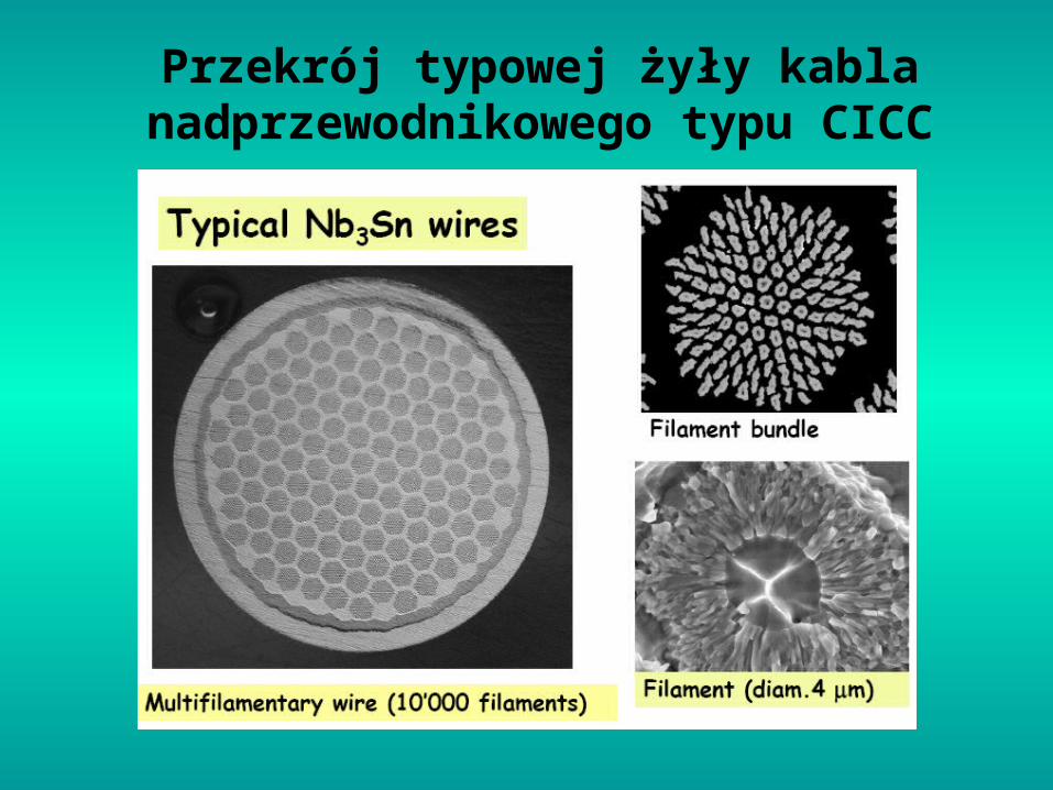
Przekrój typowej żyły kabla nadprzewodnikowego typu CICC

The ITER project
• InternationalThermonuclearExperimentalReactor
• Aim: produce energy from nuclear fusion
• High magnetic field (11 T) to confine the hot plasma
• Heavy heat loads on the coils due to neutron flux
CICC’s mandatory!
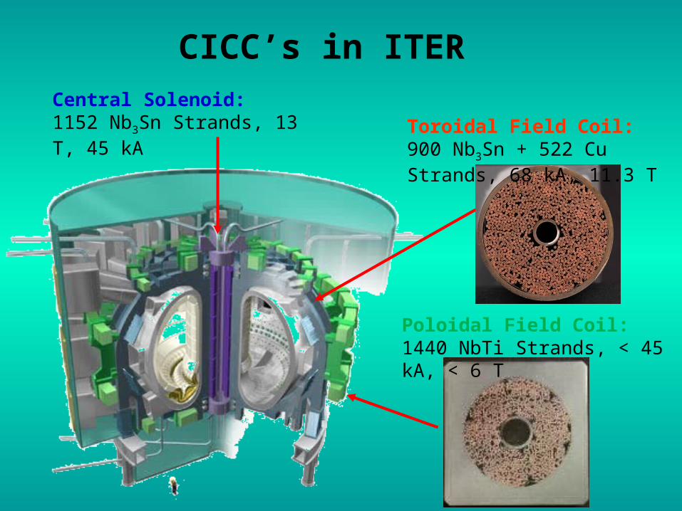
Central Solenoid: 1152 Nb3Sn Strands, 13 T, 45 kA Toroidal Field Coil: 900 Nb3Sn
+ 522 Cu Strands, 68 kA, 11.3 T
Poloidal Field Coil: 1440 NbTi Strands, < 45 kA, < 6 T
CICC’s in ITER

Gravity-buoyancy effect in a dual channel CICC
In a vertically oriented dual channel CICCwith the coolant flowing downward, power deposition in the bundle region causes the reduction of the flow velocity due to the reduced density of helium. Eventually, the back-flow can occur, leading to quench.
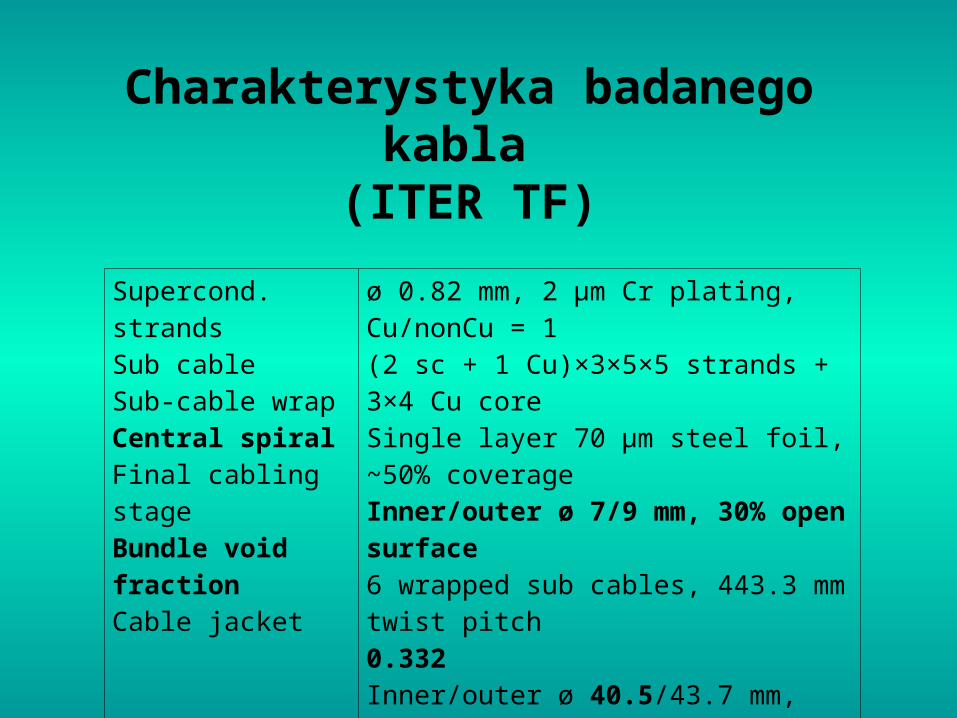
Charakterystyka badanego kabla (ITER TF)
Supercond. strands Sub cable Sub-cable wrap Central spiral Final cabling stage Bundle void fractionCable jacket
ø 0.82 mm, 2 μm Cr plating, Cu/nonCu = 1(2 sc + 1 Cu)×3×5×5 strands + 3×4 Cu coreSingle layer 70 μm steel foil, ~50% coverageInner/outer ø 7/9 mm, 30% open surface6 wrapped sub cables, 443.3 mm twist pitch0.332Inner/outer ø 40.5/43.7 mm, 316 LN steel

Schemat oprzyrządowania
próbki

Fotografie oprzyrządowania próbki

Experimental setup
SULTAN = SUpraLeitende TestANlage = Test facility for superconductors
Supercritical He:
Tinlet = 4.5 K or 6.5 K
pinlet = 1 MPa
= 10 g/smaxm
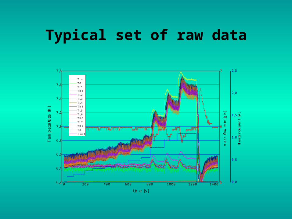
Typical set of raw data
0 200 400 600 800 1000 1200 14006,2
6,4
6,6
6,8
7,0
7,2
7,4
7,6
7,8
5
6
7
0,0
0,5
1,0
1,5
2,0
2,5
Te
mp
era
ture
[K
]
time [s]
T in T0 TL1 TR1 TL2 TL3 TL4 TR4 TL5 TL6 TR6 TL7 TR7 T8 T out
mas
s flo
w r
ate
[g/s
]
Hea
ter
curr
ent
[A]
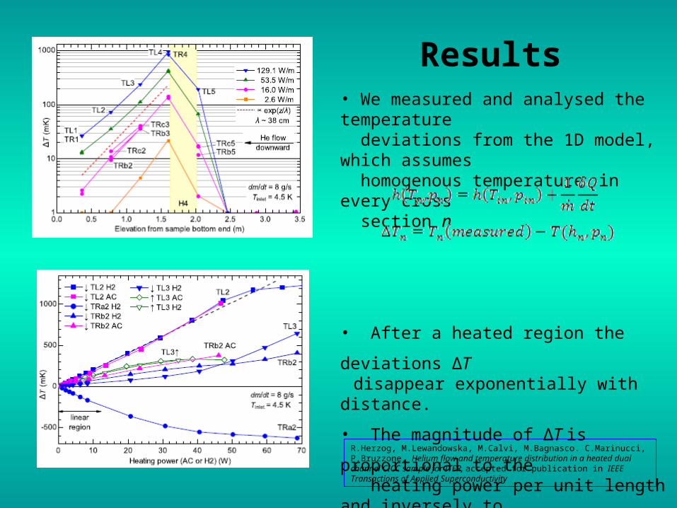
Results
R.Herzog, M.Lewandowska, M.Calvi, M.Bagnasco. C.Marinucci, P.Bruzzone, Helium flow and temperature distribution in a heated dual channel CICC sample for ITER, accepted for publication in IEEE Transactions of Applied Superconductivity
• We measured and analysed the temperature deviations from the 1D model, which assumes homogenous temperature in every cross section n
• After a heated region the deviations ΔT disappear exponentially with distance.
• The magnitude of ΔT is proportional to the heating power per unit length and inversely to the mass flow rate.• ΔTmax may be readily estimated from the obtained results.

Assessment of the helium velocity in the cooling channel and in the bundle
vH was estimated from the time delay between the rising edges of spot heater SHa current and TRa readings.

Friction factor correlations
Hole• ITER DDD
• Zanino
Bundle• ITER DDD
• Katheder
• Porous medium D-F
• Porous medium A
034.0Re45.0 HHEuf
75.32
ln5.22
)(
HhUSH D
h
fhR
299.0
039.088.11)(
h
ghhR
2/Re HUSHHh
fD
hh
R. Zanino, et al., IEEE Trans. Appl. Supercon. 10 (2000) 1066-1069
h – spiral height, w – width, g – gap
051.0
Re
5.19188.072.0
B
BEuf
0231.0
Re
5.1917953.0742.0
B
BEuf
baf BBUS Re/
14.0Re/Re/ BBBUS baf
H. Katheder, Cryogenics 34 (1994) 595–598 [ICEC supplement]M. Bagnasco, et al, CHATS AS 2008

Pressure drop and helium
velocity in TFS experimental
data and simulation
0 4 8 1 2to ta l m a ss f lo w ra te (g /s)
0
2 0 0
4 0 0
6 0 0
pres
sure
gra
dien
t at 4
.4 K
(Pa
/m) H o le fric tio n fa c to r: Z a n in o
T F S -0 7 W 1 d a taK a th e d e rP o ro u s m e d iu m D -FIT E R D D DP o ro u s m e d iu m A
0 4 8 1 2to ta l m a ss f lo w ra te (g /s)
0
2 0 0
4 0 0
6 0 0
pres
sure
gra
dien
t at 4
.4 K
(Pa
/m) H o le fric tio n fa c to r: IT E R D D D
T F S -0 7 W 1 d a taK a th e d e rP o ro u s m e d iu m D -FIT E R D D DP o ro u s m e d iu m A
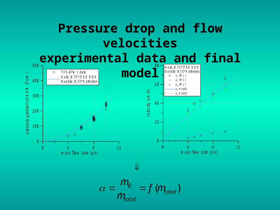
Pressure drop and flow velocitiesexperimental data and final model
0 4 8 1 2m a ss f lo w ra te (g /s)
0
1 0 0
2 0 0
3 0 0
4 0 0
5 0 0
pres
sure
gra
dien
t at 4
.4 K
(Pa
/m) T F S -0 7 W 1 d a ta
H o le : 0 .7 5 * IT E R D D DB u n d le : 0 .7 3 * K a th e d e r
0 4 8 1 2m a ss f lo w ra te (g /s)
0
2 0
4 0
6 0
8 0
velo
city
(cm
/s)
H o le : 0 .7 5 * IT E R D D DB u n d le : 0 .7 3 * K a th e d e r
v H (M L )
v H (M C )
v B (M L )
v H m o d e l
v B m o d e l
)(
totaltotal
B mfmm

Heat transfer in the ITER TF conductor

Stationary two-channel model
QTTphx
TCm
TTphx
TCm
BHBHB
pB
HBBHH
pH
temperature in the cooling hole
temperature in the cable bundle
mH
mB
phBH
TB
TH
B.Renard, et al , Evaluation of thermal gradients and thermosiphon in dual channel cable-in-conduit conductors, Cryogenics 46 (2006) 629-642
Lx
LxLPxQ
0
0/)(
)/(
,
ptotalinref
refrefpp
CmPTT
pTCC
Constant thermophysical parameters
Analytical solution
BHBHHH
BHBB hhxTT
hxTT
),(
),(

Average heat transfer coefficient between bundle and hole
0 4 8 1 2T o ta l m a ss f lo w ra te (g /s)
0
2 0 0
4 0 0
6 0 0
8 0 0
1 0 0 0
h BH
(W
/(m
2 K))
T F S
C. Marinucci, et al, Analysis of the transverse heat transfer coefficients in a dual channel ITER-type cable-in-conduit conductor, Cryogenics 47 (2007) 563-576

Temperature profiles along the sampleexperimental data and simulation
0 1 2 3 4x (m )
0
0 .5
1
1 .5
2
2 .5
T (
K)
H ea ters H 1+ H 2 P = 4 WP = 1 0 WP = 2 0 WP = 3 0 WP = 4 1 WP = 5 1 W
0 1 2 3 4x (m )
0
0 .5
1
1 .5
2
2 .5
T (
K)
H ea ter H 2P = 2 WP = 6 WP = 1 0 WP = 2 0 WP = 3 0 WP = 4 0 WP = 5 0 W
K) W/(m535
g/s 82
BH
total
h
m

Thank you for your attention


![Analizowanie działania układów hydraulicznych 311[50].O1...Hydraulika – dziedzina techniki zajmująca się elementami napędowymi, sterującymi i regulującymi maszyn, w których](https://img.dokumen.tips/doc/110x75/611b8c2891dd2b1bed65edd5/analizowanie-dziaania-ukadw-hydraulicznych-31150o1-hydraulika-a-dziedzina.jpg)