Embed Size (px)
Citation preview

832 ieee transactions on ultrasonics, ferroelectrics, and frequency control, vol. 55, no. 4, april 2008
An Ultrasonic Piezoelectric Motor UtilizingAxial-Torsional Coupling in a Pretwisted
Non-Circular Cross-Sectioned Prismatic BeamDavid Wajchman, Kuang-Chen Liu, James Friend, Member, IEEE, and Leslie Yeo
Abstract—A rotary piezoelectric motor design with sim-ple structural components and the potential for miniatur-ization using a pretwisted beam stator is demonstratedin this paper. The beam acts as a vibration converter totransform axial vibration input from a piezoelectric el-ement into combined axial-torsional vibration. The axialvibration of the stator modulates the torsional frictionforces transmitted to the rotor. Prototype stators measur-ing 6�5� 6�5� 67�5 mm were constructed using aluminum(2024-T6) twisted beams with rectangular cross-section andmultilayer piezoelectric actuators. The stall torque and no-load speed attained for a rectangular beam with an as-pect ratio of 1.44 and pretwist helix angle of 17.7� were0.17 mNm and 840 rpm with inputs of 184.4 kHz and149 mW, respectively. Operation in both clockwise andcounterclockwise directions was obtained by choosing either70.37 or 184.4 kHz for the operating frequency. The effectsof rotor preload and power input on motor performancewere investigated experimentally. The results suggest thatmotor efficiency is higher at low power input, and that effi-ciency increases with preload to a maximum beyond whichit begins to drop.
I. Introduction
The continued research on motor miniaturization stemsfrom the possibilities that would be enabled by prac-
tical motors in the submillimeter to micrometer scale. Inparticular, motors at the submillimeter length scale wouldenable a wide variety of biomedical applications. For ex-ample, micro-robots small enough to swim within the cir-culatory or digestive systems of the human body could per-form tasks such as monitoring, drug delivery, and surgicalprocedures, expanding the repertoire of tools available forminimally invasive and noninvasive surgery [1].
Conventional electromagnetic motors down to φ2 mmin diameter with a stall torque of the order of 10 µNm arecommercially available [2], [3]. However, further miniatur-ization requires technology not currently available for thefabrication of its coil components, and the scaling of mag-netic fields is not favorable for their use at smaller scalesin any case. In the late 1980s, electrostatic micromotors ofa few hundred micrometers in diameter were made possi-
Manuscript received March 9, 2007; accepted November 24, 2007.This work was supported in part by an Australian Research CouncilDiscovery Grant DP0773221 and the Monash University Small Grantand New Faculty Grant schemes.
The authors are with the MicroNanophysics Research Labora-tory, Monash University, Clayton, Melbourne, Australia (e-mail:[email protected]).
Digital Object Identifier 10.1109/TUFFC.2008.717
ble through the use of silicon micro-fabrication techniques[4]. However, these generate very low torque at high speed(in the order of 10 pNm and 10,000 rpm) [5], requiring re-duction gears accompanied by the problem of friction andwear, especially relevant at these scales.
In comparison to electrostatic motors, piezoelectric mo-tors offer promising alternatives with the advantage ofhigh torque-to-speed ratio (eschewing the need for gears),a holding torque without power expenditure, and lowelectromagnetic interference. The chief problem hinderingtheir miniaturization, as with electromagnetic motors, lieswith the difficulty of fabrication. However, with improve-ments in the machining and film deposition techniques ofpiezoelectric material, and the addition of some ingenuityin the design of the driving mechanism [6], [7], reduction insize to the few to submillimeter scale is not beyond reach[8], [9].
The class of piezoelectric motor targeted for miniatur-ization in this study is the hybrid ultrasonic motor [10].These motors employ a combination of torsional and axialvibration in the stator such that the frictional force trans-mitted to the rotor is greater during the “upstroke” thanthe “downstroke,” imparting a non-zero net torque on therotor. The direction of rotation can be changed by revers-ing the phase difference between the axial and the torsionalvibration. Conventional hybrid ultrasonic motors use bothaxially and circumferentially poled piezoelectric disks togenerate the desired stator motion. However, the complexstructure of the torsional piezoelectric element makes itvery difficult to fabricate at the submillimeter scale.
Tsujino et al. [11] demonstrated that the torsionalpiezoelectric element can be eliminated through the useof a stator with coupled axial-torsional deformation, act-ing as a vibration converter to generate the desired sta-tor motion from only axially poled piezoelectric elements.However, the helically slotted cylinders used as vibrationconverters in their centimeter-scale motors may be difficultto fabricate for micromotors.
Friend et al. [12] proposed the use of pretwisted beamswith non-circular cross sections as vibration convertersthat are simpler to fabricate on the microscale. As a firststep toward a submillimeter-scale micromotor, the pro-posed hybrid ultrasonic motor is constructed and tested inthis study at the centimeter-scale to investigate its perfor-mance characteristics (e.g., efficiency, torque-speed curve)and how they are influenced by rotor preload and inputpower.
0885–3010/$25.00 c© 2008 IEEE

wajchman et al.: an ultrasonic piezoelectric motor utilizing axial-torsional coupling 833
TABLE IFinite Element Analysis Results of the Variation of the
Fundamental Axial Resonance fA,1 and the Second
Torsional Harmonics fT,2 for Rectangular Prismatic Beams
as Aspect Ratio (h/w) Is Varied (ν = 0.33, L = 20 m,
h = 1 m).
Aspect ratio fA,1 (Hz) fT,2 (Hz)
1.00 127.8 144.01.50 127.7 133.31.66 127.7 127.72.00 127.7 116.3
II. Design and Fabrication
In this preliminary study, only the core components ofthe micromotor were constructed; the prototype consists ofan axially poled multilayer piezoelectric actuator (MLPA;AE050510; NEC/Tokin, Tokyo, Japan) bonded to a non-circular pretwisted beam with the rotor (a steel ball) bal-anced on top of the pretwisted beam.
The operation of the motor relies on the coupling be-tween the axial and torsional deformation of pretwistedbeams. Various models and techniques have been used byresearchers to explain the phenomenon, from the helical-fiber assumption and the shell theory to finite elementanalysis [13], [14]. Since the late 1970s, most beam the-ories attributed the main source of the coupling to theSt. Venant warping function of non-circular cross sections[14]–[16]. However, the validity of the theories involvingthe warping function appears limited to a small amount ofpretwist [17]. Thus finite element analysis (FEA) was usedin this study.
The elimination of the torsional piezoelectric elementmeans that the direct control over the phase difference be-tween the axial and torsional vibration is lost. The phasereversal required for bidirectional operation now dependson the beam having different harmonics with suitable vi-bration mode shapes and phase lags [18].
For an efficient conversion of the axial vibration inputfrom the MLPA into coupled axial-torsional motion at thestator-rotor interface, the motor needs to operate in a res-onance mode (ideally with matched torsional fT and axialfA resonance frequencies). Preliminary FEA was carriedout on the pretwisted beam to investigate the effect ofbeam geometry on the resonance frequency and the modeshape.
The effect of changing the cross-section aspect ratio(AR = height/width) of the rectangular prismatic (non-twisted) beams on fT and fA is shown in Table I. TheFEA-based result showed that fA is independent of AR,while fT is maximized when AR = 1 (square beams) anddecreases monotonically as AR increases. Most notably,it was shown that if AR = 1.66, the fundamental axialresonance is matched with the second torsional harmonicunder free-free boundary conditions. Since pretwist wasshown to increase fT and decrease fA [14], [17], the aspect
Fig. 1. Motor dimensions and the dotted line along which vibra-tion measurements were made for (a) torsional/flexural vibrationand (b) axial vibration. Note that the figure is not to scale, and theaxis of vibration detected by the MSA 400 is in and out of the page.
TABLE IIGeometry of the Pretwisted Beams Used in the Study.
∗
w h L N HelixBeam (mm) (mm) (mm) (rev) h/w angle
1 2.3 4.2 47.1 2 1.93 32.4◦
2 2.8 4.0 47.5 1 1.44 17.7◦
3 2.5 4.1 47.2 1.5 1.64 25.6◦
4 2.6 4.2 47.6 2 1.60 33.1◦
∗Note that N is amount of left-hand pretwist.
ratio necessary to match the resonance frequencies of thetwo desired modes is expected to be greater than 1.66 inthe presence of pretwist.
As shown in Fig. 1, the motor features a piece of axiallypoled MLPA (6.5 × 6.5 × 12 mm) bonded to a pretwistedaluminum beam using cyanoacrylate glue. Four beamsmeasuring 47.4 ± 0.3 mm in length, with different aspectratios and pretwist, were tested for efficiency comparison(geometric details are shown in Table II). Note that acountersink of 135◦ included angle was machined into thebeam tip to support the rotor—a 20-mm-diameter steelball. The beam was formed by twisting a machined longand straight aluminum beam in a jeweller’s lathe until therequired amount of pretwist was achieved. The beam wasthen cut to the correct length. The rate of twist along thelength of the beam is approximately constant using thismethod.

834 ieee transactions on ultrasonics, ferroelectrics, and frequency control, vol. 55, no. 4, april 2008
Fig. 2. Experimental set up. The height of the magnet above the ballcan be easily adjusted to change the preload. The preload, which isthe effective weight of the ball on the tip, can be measured directlyusing a scale upon which the entire motor is mounted.
III. Experimental Methods
A. Vibration Modes and Resonance Frequencies
The resonance frequencies of the beam and the associ-ated mode shapes were determined through the combineduse of an impedance analyzer (4294A; Agilent Technolo-gies, Inc., Santa Clara, CA), a scanning 3D laser Dopplervibrometer (MSA-400; Polytec GmbH, Waldbronn, Ger-many) and visual inspection.
Among the resonances, either a clockwise or a counter-clockwise rotor rotation (defined in terms of the top-downview) is generated, depending on the phase difference be-tween the axial and torsional vibration. The MSA-400 wasthus used to visualize the beam vibration. The vibrometerwas used to measure the out-of-plane vibration velocityalong the dotted lines shown in Fig. 1; the “axial line”allowed the detection of axial and y-axis bending vibra-tion while the “torsional line” detected torsional and x-axis bending vibration. An accurate determination of thetorsional resonance frequency can also be performed usingthe continuous measurement function of the vibrometer byadjusting the frequency of the signal generator and notingthe frequencies that produce the highest torsional vibra-tion velocity.
B. Torque-Speed Measurements
To investigate the effect of rotor preload and inputpower on the performance characteristics of the motor, anexperimental method similar to that proposed by Friendet al. [19] was used. The motor was set up as shown inFig. 2, with the MLPA end of the stator assembly looselyattached to the surface of an electronic scale using double-sided tape, and the steel ball balanced on the tip of thepretwisted beam as the rotor. Note that beam 2 was se-lected for this experiment due to its lower AR, whichmakes it easier to balance the rotor. With the electronicscale tared before the steel ball was placed upon the stator,a direct measurement of the preload was made.
TABLE IIIClockwise (cw) and Counter-Clockwise (ccw) Driving
Frequencies for Beams 1 Through 4.
Beam CW (kHz) 1 CW (kHz) 2 CCW (kHz)
1 62.5 88.2 35.92 70.4 184.43 66.2 93.4 223.14 95.5 174.1
A rare earth magnet was held above the steel ball usinga vertical stage, allowing the rotor preload to be variedfrom the full weight of the ball (320 mN) to as low as25 mN. Due to the magnetic force being a function of theseparation distance to the fourth power, the adjustmentof the vertical stage must be made carefully. This methodallowed quick and easy preload changes without adjustingthe rotational moment of inertia of the rotor, an importantpoint when comparing the results.
The rotation of the ball was measured using an opticaldisplacement sensor (D63H; Philtec Inc., Annapolis, MD)in conjunction with a printed pattern of uniformly spacedstripes attached to the side of the steel ball (not shown).The voltage-time signal from the sensor can be convertedto a velocity-time signal using the following relationship:
ω =2π/S
∆tp, (1)
where ω is an average rotational speed, S is the number ofstripes on the ball, and ∆tp is the peak-trough time fromthe sensor output.
The torque-speed curve and the friction coefficient ofthe motor can then be estimated using its transient re-sponse by switching on the power when the rotor is at rest,allowing it to reach steady-state speed, and then cuttingoff the power to observe the motor’s braking characteris-tics [19], [20].
The efficiency η of the motor at a particular power in-put and loading condition is defined here as the ratio ofthe peak mechanical power output over the average powerinput. An oscilloscope (3014B; Tektronix, Beaverton, OR)with calibrated voltage and current probes was used tomeasure the average power input.
IV. Results and Discussion
A. Vibrometer Results
Frequency scans up to the 230-kHz range were per-formed on the four motor-beam configurations; Table IIIlists the frequencies where significant rotation is gener-ated. A comparison of beam 2’s vibration results at theclockwise frequency (70.3 kHz) and counterclockwise fre-quency (183.3 kHz) is shown in Fig. 3. The measurementswere made along the dotted lines in Fig. 1. The nearly oddsymmetry seen along the torsional line shows that torsional

wajchman et al.: an ultrasonic piezoelectric motor utilizing axial-torsional coupling 835
Fig. 3. Vibrometer results at (a) 70.37 kHz and (b) 184.4 kHz. Thetorsional frequencies are shown in phase to each other, which indi-cates that the axial displacements are out of phase by approximately90◦ at the two different frequencies.
motion dominates over x-axis bending vibration; however,the slight imbalance in vibration velocity along the axialline (most likely caused by inaccuracies in the fabricationof the beams) suggests the presence of a small amount ofy-axis bending vibration, which may explain the rotor’stendency to wobble under very low preloads.
The results of the two frequencies are aligned so that thetorsional modes are shown in phase with each other. Thephase lag φ of the axial velocity relative to the torsionalvelocity is seen by inspection to be φ ≈ 45◦ at 70.37 kHzand φ ≈ −45◦ at 184.4 kHz. The torque transmitted tothe rotor is the largest over the part of the cycle wherethe axial acceleration is positive upwards, which occursfor 184.4 kHz when −160◦ < θ < 20◦, and for 70.4 kHzwhen −90◦ < θ < 90◦. This explains why the ball spins inopposite directions from 70.4 kHz to 184.4 kHz.
B. Stall Torque and Steady-State Speed Estimate
A stator-rotor model with sufficient complexity to pre-dict the motor performance is beyond the scope of thispaper. However, simple estimates of the stall torque andthe steady-state rotor speed can be made based on thevibration velocity of the stator.
With an input frequency in the order of 100 kHz, andaxial vibration amplitude in the order of 1 µm, the stator’saxial acceleration would be in the order of 106 m/s2, com-pared to the 10 m/s2 gravitational acceleration. When theaxial acceleration of the stator is greater than the gravita-tional acceleration holding the rotor and stator together,the rotor trajectory will be one of repeated separation andcollision with the stator. Frictional impulse then becomesthe chief torque transmission mechanism between the sta-tor and the rotor.
TABLE IVComparison of the Stator’s Peak Torsional Speed and the
Rotor’s Steady-State Speed for Beam 4 at 174.1 kHz.
Power Stator Rotor Stallinput speed speed Speed torque(mW) (rad/s) (rad/s) ratio (mNm)
60.6 151 97 0.64 0.2184.8 187 110 0.59 0.2596.8 176 120 0.68 0.28
Assuming uniform pressure is present over the stator-rotor contact, the frictional torque impulse T is related tothe axial impulse F by the following equation:
T = rcµkF , (2)
where rc ≈ 1 mm is the radius of the countersink on thebeam tip and represents the radius of the contact line, andµk ≈ 0.5 is the kinetic coefficient of friction between steeland aluminum [21]. Assuming that the stator mass is muchgreater than the rotor mass, and that the coefficient ofrestitution is zero, then the separation and landing speedof the rotor would be equal to the stator’s axial vibrationspeed us. Thus the axial impulse F is
F = 2mrus, (3)
where mr = 32 g is the mass of the rotor. The rotationalspeed of the rotor before ω+ and after ω− each impact isrelated to the torque impulse by
T = Jb(ω+ − ω−), (4)
where Jb is the moment of inertia of the rotor. For aparabolic rotor trajectory, the time between collisions withthe stator ∆tc is estimated to be
∆tc = 2us/g. (5)
The average torque T over the time between each collisioncan thus be estimated by combining (2) through (5):
T = Jb(ω+ − ω−)
∆tc= rcµkmrg. (6)
Eq. (6) gives a torque estimate of 0.16 mNm, which is ofthe same order of magnitude as the measured stall torqueshown in Table IV.
The maximum possible rotational rotor speed is thepeak torsional vibration speed of the stator (from here ondenoted as the “stator speed”). Depending on the portionof the stator vibration over which torque is transmitted,the rotor speed would approach some fraction of the sta-tor speed. The measured results for beam 4 at 174.1 kHz(shown in Table IV) indicate that the ratio of the rotorspeed over the stator speed (or simply the “speed ratio”)is 0.64 ± 0.05. The speed ratios are consistently less thanone, and this could be expected since the stator speed inTable IV is measured without the rotor, while the rotor
836 ieee transactions on ultrasonics, ferroelectrics, and frequency control, vol. 55, no. 4, april 2008
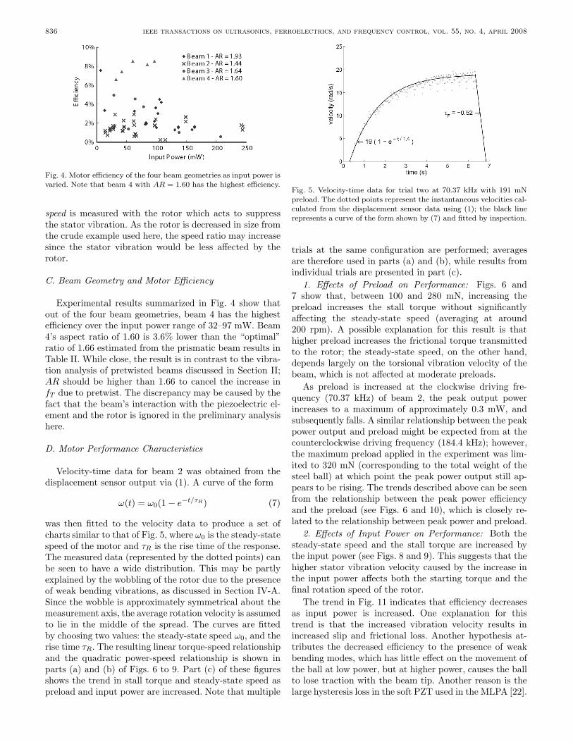
Fig. 4. Motor efficiency of the four beam geometries as input power isvaried. Note that beam 4 with AR = 1.60 has the highest efficiency.
speed is measured with the rotor which acts to suppressthe stator vibration. As the rotor is decreased in size fromthe crude example used here, the speed ratio may increasesince the stator vibration would be less affected by therotor.
C. Beam Geometry and Motor Efficiency
Experimental results summarized in Fig. 4 show thatout of the four beam geometries, beam 4 has the highestefficiency over the input power range of 32–97 mW. Beam4’s aspect ratio of 1.60 is 3.6% lower than the “optimal”ratio of 1.66 estimated from the prismatic beam results inTable II. While close, the result is in contrast to the vibra-tion analysis of pretwisted beams discussed in Section II;AR should be higher than 1.66 to cancel the increase infT due to pretwist. The discrepancy may be caused by thefact that the beam’s interaction with the piezoelectric el-ement and the rotor is ignored in the preliminary analysishere.
D. Motor Performance Characteristics
Velocity-time data for beam 2 was obtained from thedisplacement sensor output via (1). A curve of the form
ω(t) = ω0(1 − e−t/τR) (7)
was then fitted to the velocity data to produce a set ofcharts similar to that of Fig. 5, where ω0 is the steady-statespeed of the motor and τR is the rise time of the response.The measured data (represented by the dotted points) canbe seen to have a wide distribution. This may be partlyexplained by the wobbling of the rotor due to the presenceof weak bending vibrations, as discussed in Section IV-A.Since the wobble is approximately symmetrical about themeasurement axis, the average rotation velocity is assumedto lie in the middle of the spread. The curves are fittedby choosing two values: the steady-state speed ω0, and therise time τR. The resulting linear torque-speed relationshipand the quadratic power-speed relationship is shown inparts (a) and (b) of Figs. 6 to 9. Part (c) of these figuresshows the trend in stall torque and steady-state speed aspreload and input power are increased. Note that multiple
Fig. 5. Velocity-time data for trial two at 70.37 kHz with 191 mNpreload. The dotted points represent the instantaneous velocities cal-culated from the displacement sensor data using (1); the black linerepresents a curve of the form shown by (7) and fitted by inspection.
trials at the same configuration are performed; averagesare therefore used in parts (a) and (b), while results fromindividual trials are presented in part (c).
1. Effects of Preload on Performance: Figs. 6 and7 show that, between 100 and 280 mN, increasing thepreload increases the stall torque without significantlyaffecting the steady-state speed (averaging at around200 rpm). A possible explanation for this result is thathigher preload increases the frictional torque transmittedto the rotor; the steady-state speed, on the other hand,depends largely on the torsional vibration velocity of thebeam, which is not affected at moderate preloads.
As preload is increased at the clockwise driving fre-quency (70.37 kHz) of beam 2, the peak output powerincreases to a maximum of approximately 0.3 mW, andsubsequently falls. A similar relationship between the peakpower output and preload might be expected from at thecounterclockwise driving frequency (184.4 kHz); however,the maximum preload applied in the experiment was lim-ited to 320 mN (corresponding to the total weight of thesteel ball) at which point the peak power output still ap-pears to be rising. The trends described above can be seenfrom the relationship between the peak power efficiencyand the preload (see Figs. 6 and 10), which is closely re-lated to the relationship between peak power and preload.
2. Effects of Input Power on Performance: Both thesteady-state speed and the stall torque are increased bythe input power (see Figs. 8 and 9). This suggests that thehigher stator vibration velocity caused by the increase inthe input power affects both the starting torque and thefinal rotation speed of the rotor.
The trend in Fig. 11 indicates that efficiency decreasesas input power is increased. One explanation for thistrend is that the increased vibration velocity results inincreased slip and frictional loss. Another hypothesis at-tributes the decreased efficiency to the presence of weakbending modes, which has little effect on the movement ofthe ball at low power, but at higher power, causes the ballto lose traction with the beam tip. Another reason is thelarge hysteresis loss in the soft PZT used in the MLPA [22].

wajchman et al.: an ultrasonic piezoelectric motor utilizing axial-torsional coupling 837
Fig. 6. Clockwise rotation characteristics of the motor at 70.37 kHz versus applied preload.
Fig. 7. Counterclockwise rotation characteristics of the motor at 184.4 kHz versus applied preload.
Fig. 8. Clockwise rotation characteristics of the motor at 70.37 kHz versus input power.
Fig. 9. Counterclockwise rotation characteristics of the motor at 184.4 kHz versus input power.

838 ieee transactions on ultrasonics, ferroelectrics, and frequency control, vol. 55, no. 4, april 2008
Fig. 10. Beam 2’s motor efficiency versus applied preload at (a) the clockwise and (b) the counterclockwise frequencies with average inputpower of 100 and 45 mW, respectively.
Fig. 11. Beam 2’s motor efficiency versus input power at (a) the clockwise and (b) the counterclockwise frequencies with preload fixed at320 mN.
E. Comparisons with Other Motors
The measured efficiency of the motor varied consid-erably, depending on the beam geometry, input power,and rotor preload. It ranged from 3% for beam 2 to 8%for beam 4. The maximum torque attained was approx-imately 0.28 mNm (beam 4 with 96.8 mW input powerat 174.1 kHz), and the maximum speed was 1360 rpm(beam 2 with 240 mW input power at 184.4 kHz). Thisis fairly moderate performance for a motor of this size.The in-plane shearing motor reported in [19], for example,produces a comparable peak torque of 0.27 mNm and apeak rotation speed of 800 rpm, but is only one-tenth thevolume of the motor in this study.
Compared to other motors, this motor does not havegreat efficiency. The hybrid ultrasonic motor [20] and thein-plane shearing motor mentioned above have an effi-ciency of up to 40%; even electromagnetic motors with2-mm diameter have efficiency in the 25–35% range. How-ever, the large performance variation observed in this pa-per suggests that further improvements in the efficiency ispossible. An important point to note is that the efficiencyquoted here was determined using a fixed-frequency drive,implying that if the highest efficiency operating frequencyof the motor shifts due to heating or hysteresis in the piezo-electric material, the results would have been affected. Thisis always a difficult decision—either include a drive circuit
that tracks the operating frequency and argue it does notaffect the efficiency, or exclude it and suffer the effects.Ultimately, the advantage of the present motor is that itwould be easier to miniaturize than other motor designs.
V. Conclusions
An ultrasonic motor utilizing a rectangular cross-sectioned pretwisted beam and an axially poled MLPA waspresented. It was shown that, as a result of the beam’s ge-ometry, a coupled axial-torsion vibration can be realizedat the tip. This vibration can be used to spin a rotor. Dueto the presence of different resonance torsional modes inthe beam, the different phase lags between the axial andtorsional modes allow bidirectional operation.
Four beam geometries were tested, and the best effi-ciency was achieved by beam 4, which has an aspect ra-tio of 1.6 and helix angle of 33.1◦. This aspect ratio isvery close to the optimal value predicted from results fora prismatic beam. The maximum efficiency achieved bybeam 4 was 8.5% at 174.1 kHz with an input power of96.8 mW. Tests on beam 2 showed that preload increasedthe stall torque without significant effects on the steady-state speed, though efficiency appears to first rise and thenfall. The effect of raising input power was to increase boththe stall torque and the steady-state speed at the expenseof efficiency.

wajchman et al.: an ultrasonic piezoelectric motor utilizing axial-torsional coupling 839
The generation of weak bending modes is a concernhere, particularly as miniaturization is considered. Thesemodes are believed to occur from inaccuracies in fabrica-tion of the beams, particularly at the ends. Fortunately,techniques such as LIGA technology and laser machiningfor microfabrication offer accuracies superior to the meth-ods used in this preliminary study.
While the efficiency was low in this study, improvementmay be possible if coupling is optimized by matching thetorsional and axial resonance frequencies. Additionally, themotor’s strength lies with its simple structure, which pavesthe way for further miniaturization.
Acknowledgments
The authors thank the Monash University EngineeringWorkshop staff who machined the aluminum beams usedin this study.
References
[1] B. Behkam and M. Sitti, “E. coli inspired propulsion for swim-ming microrobots,” in Proc. ASME Dynam. Syst. Contr. Div.,vol. 73, 2004, pp. 1037–1041.
[2] Namiki Precision Jewel Co., Ltd., Namiki DC Brushless MotorSBL02-06. Tokyo, Japan, 2007.
[3] Faulhaber, Faulhaber Micro Brushless DC-Motor Series 0206B. 2006–2007 ed., Group, Schonaich, Germany, 2007.
[4] Y.-C. Tai and R. S. Muller, “IC-processed electrostatic syn-chronous micromotors,” Sens. Actuators, vol. 20, pp. 49–55,1989.
[5] M. Mehragany and Y.-C. Tai, “Surface micromachined mecha-nisms and micromotors,” J. Micromech. Microeng., vol. 1, pp.73–85, 1991.
[6] T. Morita, “Miniature piezoelectric motors,” Sens. Actuators A,vol. 103, pp. 291–300, 2003.
[7] K. Uchino, S. Cagatay, B. Koc, S. Dong, P. Bounchilloux, andM. Strauss, “Micro piezoelectric ultrasonic motors,” J. Electro-ceram., vol. 13, pp. 393–401, 2004.
[8] J. Friend, Y. Gouda, K. Nakamura, and S. Ueha, “A 5-mm3
bidirectional precision linear microactuator—The baltan actua-tor,” IEEE Trans. Ultrason., Ferroelect., Freq. Contr., vol. 53,no. 6, pp. 1160–1168, June 2006.
[9] M. Hogg, J. Friend, and L. Yeo, “A bidirectional linear ultrasonicmicromotor nearly meeting Feynman’s challenge,” Appl. Phys.Lett., to be published.
[10] K. Nakamura, M. Kursawa, and S. Ueha, “Design of a hybridtransducer type ultrasonic motor,” IEEE Trans. Ultrason., Fer-roelect., Freq. Contr., vol. 49, no. 4, pp. 395–401, July 1993.
[11] J. Tsujino, R. Suzuki, and H. Yasojima, “Load characteristics ofultrasonic rotary motor using a longitudinal-torsional vibrationconverter,” in Proc. IEEE Ultrason. Symp., 1996, pp. 377–382.
[12] J. Friend, K. Nakamura, and S. Ueha, “Torsional transducersusing asymmetrically twisted bars with axially-poled PZT,” inProc. Acoust. Soc. Jpn., Tokyo, Japan, vol. 1-P-25, 2003, pp.1277–1278.
[13] C. Chu, “The effect of initial twist on the torsional rigidity ofthin prismatical bars and tubular members,” in Proc. First U.S.Nat. Congr. Appl. Mech., 1951, pp. 265–269.
[14] A. Rosen, “Structural and dynamic behavior of pretwisted rodsand beams,” Appl. Mech. Rev., vol. 44, no. 12, pt. 1, pp. 483–515, 1991.
[15] D. H. Hodges, “Torsion of pretwisted beams due to axial load-ing,” J. Appl. Mech., vol. 47, pp. 393–397, June 1980.
[16] S. Krenk, “The torsion-extension coupling in pretwisted elasticbeams,” Int. J. Solids Struct., vol. 19, no. 1, pp. 67–72, 1983.
[17] K. Liu, J. Friend, and L. Yeo, “Vibration analysis of pretwistedbeams for the design of hybrid axial-torsional transducers,” in
Proc. 48th AIAA/ASME/ASCE/AHS/ACS Structures, Struc-tural Dynamics, Materials Conf., 2007, art. no. AIAA-2007-2278, pp. 1–20.
[18] J. Friend, J. Satonobu, K. Nakamura, S. Ueha, and D. Stutts, “Asingle-element piezoelectric tuning fork linear actuator,” IEEETrans. Ultrason., Ferroelect., Freq. Contr., vol. 50, no. 2, pp.179–186, 2003.
[19] J. Friend, K. Nakamura, and S. Ueha, “A piezoelectric micro-motor using in-plane shearing of PZT elements,” IEEE/ASMETrans. Mechatron., vol. 9, no. 3, pp. 467–473, 2004.
[20] K. Nakamura, M. Kurosawa, H. Kurebayashi, and S. Ueha, “Anestimation of load characteristics of an ultrasonic motor by mea-suring transient responses,” IEEE Trans. Ultrason., Ferroelect.,Freq. Contr., vol. 38, pp. 481–485, 1991.
[21] E. A. Avallone and T. Baumeister, III, Eds. Marks’ Stan-dard Handbook for Mechanical Engineers. 10th ed. New York:McGraw-Hill, 1996.
[22] S. Takahashi, “Multilayer piezoelectric ceramic actuators andtheir applications,” Jpn. J. Appl. Phys., vol. 24, suppl. 24-2, pp.41–45, 1986.
David Wajchman was born in Melbourne,Australia, on June 29, 1983. He receivedthe BE/BTech degree in mechanical andaerospace engineering from Monash Univer-sity, Melbourne, Australia, in 2006. He is aparticipating member of Engineers WithoutBorders Australia.
Kuang-Chen Liu was born in 1982. He re-ceived the B.S. (mathematics)/B.Eng. (me-chanical) double degree in 2006, from MonashUniversity, Melbourne, Australia, where he iscontinuing studies as a postgraduate student.His research interests include structural dy-namics, theory of elasticity, and piezoelectricmotors.
James Friend was born in Lubbock, Texas,on September 13, 1970. He received the B.S.degree in aerospace engineering, and the M.S.and Ph.D. degrees in mechanical engineeringfrom the University of Missouri-Rolla in 1992,1994, and 1998, respectively. He received anaward for the encouragement of young scien-tists at the Symposium for Ultrasonic Elec-tronics and Engineering in 2003 for a presen-tation on acoustic waveguides, and an awardin 2004 for a presentation on the Scream actu-ator at the Spring Meeting of the Acoustical
Society of Japan. From 2001 to 2004, Dr. Friend was an assistant pro-fessor at the Precision and Intelligence Laboratory, Tokyo Instituteof Technology, and is now an associate professor in and deputy headof the Department of Mechanical Engineering at Monash University,Melbourne, Australia, with research interests in micro/nanodevices.He is a member of IEEE, ASME, and a committee member of IEEENanotechnology for Biology.

840 ieee transactions on ultrasonics, ferroelectrics, and frequency control, vol. 55, no. 4, april 2008
Leslie Yeo is currently Senior Lecturer inthe Department of Mechanical Engineering atMonash University, Melbourne, Australia, fol-lowing a postdoctoral stint at the Universityof Notre Dame, Notre Dame, IN, in 2003/4and industrial experience as a mathematicalmodeller at Det Norske Veritas, Oslo, Nor-way, in 2002/3. Dr. Yeo had previously com-pleted his M.Eng. and Ph.D. degrees in chem-ical engineering at Imperial College London in1998 and 2002, respectively, for which he wasawarded the Dudley Newitt prize for a theo-
retical/computational thesis of outstanding merit. His Ph.D. studieswere supported through two awards, namely, the Overseas ResearchScholarship and the University of London Knight Studentship in Sci-ence and Engineering. Dr. Yeo’s research interests are primarily inmicroscale and nanoscale phenomena, and, in particular, microflu-idics. He is a member of the editorial board of the American Instituteof Physics journal Biomicrofluidics.


![Piezoelectric Ultrasonic Micromotors - [email protected]](https://img.dokumen.tips/doc/110x75/6204ee814c89d3190e0cabb2/piezoelectric-ultrasonic-micromotors-emailprotected.jpg)