Embed Size (px)
Citation preview

The 6th International Supercritical CO2 Power Cycles SymposiumMarch 27 - 29, 2018, Pittsburgh, Pennsylvania
An Overview of the Rolls-Royce sCO2-Test Rig Project at CranfieldUniversity
Eduardo AnselmiCranfield University
Bedfordshire, United [email protected];
Vassilios PachidisCranfield University
Bedfordshire, United [email protected]
Michael JohnstonHeatric Division of Meggitt UK Ltd
Poole, United [email protected]
Ian BunceRolls-Royce plc
Derby, United [email protected]
Pavlos ZachosCranfield University
Bedfordshire, United [email protected]
ABSTRACT
An experimental facility is currently under development at Cranfield University, aiming to exploresupercritical carbon dioxide as a working fluid for future bottoming power cycle applications for Rolls-Royce. The initial objectives of this experimental program are to de-risk and demonstrate the robustnessof a closed loop system, as well as to prove the function and performance of individual components andvarious measurement and control modules. This paper describes the planning and development phasesof the test facility and summarises the lessons learnt from the component specification and componentinterface processes.
INTRODUCTION
The combination of high fuel prices and more stringent emissions legislation (particularly IMO Tier III [1])has led to an increasing interest in waste heat recovery technologies across the marine sector. Gasturbines reject a large quantity of heat to the atmosphere compared with their reciprocating counterparts.Therefore recovering this heat using bottoming cycles, which have the potential to increase combinedcycle efficiencies and offer additional electrical/mechanical power, is a topic of special interest in themarine propulsion community. The potential of a supercritical carbon dioxide (sCO2) bottoming cycle isreasonably well documented in the literature. However, there are limited instances of demonstration anda single publicized commercial offering. Three UK related entities: Rolls-Royce plc, Heatric Meggitt andCranfield University, have formed a collaborative consortium in order to generate data to validate abusiness case capable of reducing the level of technical and commercial risk associated with this noveland potentially valuable technology.
Despite the general enthusiasm about the unique advantages that supercritical CO2 power systemscould offer, it has been recognized that there is a need to address a wide variety of technologicalchallenges before achieving a commercial prototype. The areas identified as critical for success were:
• Control of the working fluid throughout the thermodynamic cycle, recognizing “real gas” effects• World-class transient modelling capability and turbomachinery design• Identification or development of high-temperature materials fit for purpose• Development of the auxiliary systems that are needed to realize the cycle
Additionally, the consortium believes that it has identified an important gap between the advanced

research efforts reported by others. Consequently, the consortium has been exploring the technologiesand resources that will be required to close this gap. The consortium has also discovered that it isnecessary to assess the capability and capacity of the UK supply chain to provide goods and servicesfor supercritical CO2 waste heat recovery technologies.
Carbon dioxide applications are already known in the oil & gas and refrigeration industries and thereforeimportant lessons can be learned from them. The challenge is to correctly scale equipment and controlmethods to be used for each stage of the experiment. Rig tests are bespoke by their nature, withassociated technical and budgetary risks. Scaling introduces a risk because of the reliance on systemand control modelling in the design of systems and components. Specifically, there is a risk that resultsgenerated from a ‘scaled’ rig will not be directly applicable to the design of a full scale system. We notethat the Naval Nuclear Laboratory has already demonstrated [2] that over sizing components (to accountfor unknowns) will not guarantee a controllable off-design transient performance. After evaluating thelessons learned from existing CO2 test facilities of this type [3] - [12], the consortium concluded that(noting budgetary constraints) the focus should be on testing compressors and main heat exchangers(MHEX) suitable for systems within a range of 100 to 300 kWe.
During the assessment of technologies where CO2 in the supercritical state is used as a working fluid, itwas found that pumps and valves for applications such as carbon capture and storage and carboncapture and utilization, are technically mature and reliable. However, the specified mass flow,component size and costs for the available equipment are not ideally suited to exploratory research. Bycontrast, the refrigeration industry, driven by incremental regulation on the sale of equipment containingfluorinated green gas (F gas) since 2007, has been moving towards low cost technologies using R744refrigerant (Carbon Dioxide). Equipment, designed for application in food retail refrigeration anddomestic heat pumps, comprises technologies where the CO2 can be operated in either subcritical ortranscritical states. From an experimental research viewpoint, one advantage of this equipment is thesize: typically larger than those used in laboratories but commercially available and relatively compact.The initial configuration of the facility at Cranfield University has been designed to capture the keyelements of operability and controllability of CO2 as a working fluid through the use of a transcriticalcirculation loop intended for use in refrigeration systems.
This paper describes the planning and development of the modular test facility designed by theconsortium to be a reliable source of carbon dioxide in a supercritical state.
TEST RIG DEVELOPMENT ROADMAP
The aim of this project is to design, build and commission a closed loop sCO2 system to enable criticalcomponent testing and whole cycle demonstration of a representative waste heat recovery system. As astarting point, a simple recuperated Brayton cycle has been selected as a baseline reference system.This design choice allows interfaces with data acquisition and control systems to be designed forprogressive step wise development and implementation of ever more complex configurations; such assimple recuperated split shafts or nested expansion configurations.
The step wise development progression of the facility will be as follows:
1. Development of a baseline sCO2 closed loop facility and specification of required componentsand operating processes.
2. Development of a high-pressure gas-to-CO2 compact heat exchanger.3. Design and development of a sCO2 compression system. This includes system and mechanical
design definition for the system and components in the main gas flow path.4. Development and implementation of data acquisition and rig control systems for operating the
test loop:• Compressor speed / recirculation valves• Cooling flow• Start-up/shut-down procedures• CO2 inventory control
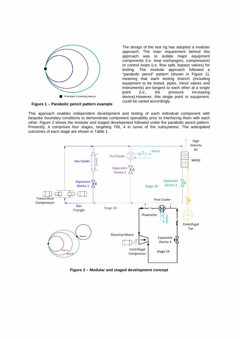
Figure 1 – Parabolic pencil pattern example
The design of the test rig has adopted a modularapproach. The main requirement behind thisapproach was to isolate major equipmentcomponents (i.e. heat exchangers, compressors)or control loops (i.e. flow split, bypass valves) fortesting. The modular approach followed a“parabolic pencil” pattern (shown in Figure 1),meaning that each testing branch (includingequipment to be tested, pipes, minor valves andinstruments) are tangent to each other at a singlepoint (i.e., the pressure increasingdevice).However, this single point or equipment,could be varied accordingly.
This approach enables independent development and testing of each individual component withbespoke boundary conditions to demonstrate component operability prior to interfacing them with eachother. Figure 2 shows the modular and staged development followed under the parabolic pencil pattern.Presently, it comprises four stages, targeting TRL 4 in some of the subsystems. The anticipatedoutcomes of each stage are shown in Table 1.
Figure 2 – Modular and staged development concept

Table 1- Roadmap of the test rig development and its outcomes
Stage Components Outcomes
GTCirculation compressor,gas cooler, expansiondevice 1 (refrigeration)
- De-risk sCO2 loop.- Demonstrate component/rig robustness and proof ofconcept.- Verify transcritical compressor performance.- Assess procedures for filling / starting up / shuttingdown.- Demonstrate pressure and temperature acquisitiondata at supercritical state.
1ACirculation compressor,
pre cooler, industrialexpansion device 2
- Verify contractual performance of high pressurefacilities.- Characterize pre cooler performance.- Validation of SIMULINK models.- Demonstrate pressure and temperature control coolingsystem.- Assess control system for inventory control
1BMHEX, fan, circulationcompressor, expansion
device 3
- Test MHEX performance (cold run – only air).- Assess key technical issues for further development(thermal expansion).
2ACentrifugal compressor,post cooler, expansion
device 4
- De-risk compressor installation.- Characterize pre cooler performance.- Develop supporting technology of the turbomachinerydesign:
• Bearing type, thrust loading, bearing cooling,sealing technologies, and rotor windage losses.
- Validation of SIMULINK models.- Demonstrate pressure and temperature control atsupercritical state.- Demonstrate compressor performance atrepresentative PR.
RIG DESIGN CONSIDERATIONS
The work undertaken by SANDIA [8] was reviewed as a prelude to generating the specifications for thetest rig at Cranfield. With their sCO2 compression test loop, SANDIA have shown [8] that (from asystems control point of view) the ‘real gas’ effects of operating close to the critical point are challenging.Achieving simultaneously set-points, for the expansion pressure and water temperature, demand thedevelopment of a relatively complex control system. However, when decomposing the problem, it wasidentified that the loop process consisted of three steps: compression, expansion and heat rejection.Although the steps are in a different sequence, these steps are the same for testing reciprocatingcompressors in the refrigeration industry. Hence, the consortium elected to use positive displacementcompressors sourced from the refrigeration industry for the first configuration of our rig test. We havecalled this step the ‘gas triangle’ (see below). In this arrangement the working fluid is compressed,cooled and then expanded. This approach has allowed us to build the control system for the test riggradually (and independently). Hence, the control algorithms for the first stage (expansion device andcooling water) will be developed using only the transcritical compressors. Control algorithms for the rigwith the MHEX and for the compressor will be developed later. Figure 3 illustrates the principle behindoperating transcritical compressors in a “gas triangle”.
The ’gas triangle’ approach allows us to test different technologies for heat exchange and gasexpansion, as shown in Figure 2. Additionally, it allows us to operate the rig with a low cost source ofCO2 (commercially available R744: 99.9% purity carbon dioxide with a moisture content of 10vpm).
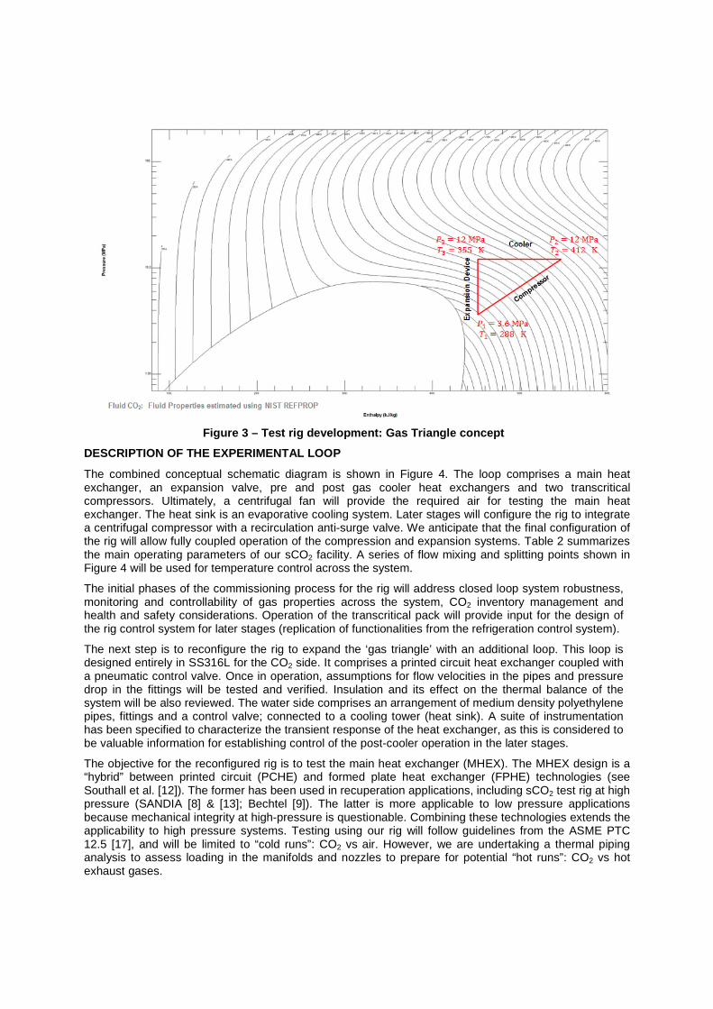
Figure 3 – Test rig development: Gas Triangle concept
DESCRIPTION OF THE EXPERIMENTAL LOOP
The combined conceptual schematic diagram is shown in Figure 4. The loop comprises a main heatexchanger, an expansion valve, pre and post gas cooler heat exchangers and two transcriticalcompressors. Ultimately, a centrifugal fan will provide the required air for testing the main heatexchanger. The heat sink is an evaporative cooling system. Later stages will configure the rig to integratea centrifugal compressor with a recirculation anti-surge valve. We anticipate that the final configuration ofthe rig will allow fully coupled operation of the compression and expansion systems. Table 2 summarizesthe main operating parameters of our sCO2 facility. A series of flow mixing and splitting points shown inFigure 4 will be used for temperature control across the system.
The initial phases of the commissioning process for the rig will address closed loop system robustness,monitoring and controllability of gas properties across the system, CO2 inventory management andhealth and safety considerations. Operation of the transcritical pack will provide input for the design ofthe rig control system for later stages (replication of functionalities from the refrigeration control system).
The next step is to reconfigure the rig to expand the ‘gas triangle’ with an additional loop. This loop isdesigned entirely in SS316L for the CO2 side. It comprises a printed circuit heat exchanger coupled witha pneumatic control valve. Once in operation, assumptions for flow velocities in the pipes and pressuredrop in the fittings will be tested and verified. Insulation and its effect on the thermal balance of thesystem will be also reviewed. The water side comprises an arrangement of medium density polyethylenepipes, fittings and a control valve; connected to a cooling tower (heat sink). A suite of instrumentationhas been specified to characterize the transient response of the heat exchanger, as this is considered tobe valuable information for establishing control of the post-cooler operation in the later stages.
The objective for the reconfigured rig is to test the main heat exchanger (MHEX). The MHEX design is a“hybrid” between printed circuit (PCHE) and formed plate heat exchanger (FPHE) technologies (seeSouthall et al. [12]). The former has been used in recuperation applications, including sCO2 test rig at highpressure (SANDIA [8] & [13]; Bechtel [9]). The latter is more applicable to low pressure applicationsbecause mechanical integrity at high-pressure is questionable. Combining these technologies extends theapplicability to high pressure systems. Testing using our rig will follow guidelines from the ASME PTC12.5 [17], and will be limited to “cold runs”: CO2 vs air. However, we are undertaking a thermal pipinganalysis to assess loading in the manifolds and nozzles to prepare for potential “hot runs”: CO2 vs hotexhaust gases.

Figure 4 – Schematic of the envisaged S-CO2 test rig. Blue: Stage 1 loop, Black: Stage 2 loop
Table 2- Design parameters for the S-CO2 rig test facility.
Parameter Stages 1A / 1B Stage 2
Overall Pressure Ratio 2.66 1.95Top pressure [MPa] 12 15Top temperature [K] 440 350
Bottom pressure [MPa] 4.5 7.7Inlet compressor temperature [K] 294 305
CO2 mass flow [kg/s] <1 5CO2 mass flow to MHEX [kg/s] 0.3
Transcritical compressors sourced from the refrigeration industry deliver the specified flow rate of 1 kg/sfor the first configuration of the rig. The compressors are assembled into a pack rack, similar to the onesused in refrigeration, as shown in Figure 5. The pack includes a brazed plate evaporator and a gas cooler(not shown in the picture). The intent of the evaporator is to assure vaporization of liquid CO2 during thestart-up process. This arrangement (evaporator and compressors) is being assessed as an option for thesupply of supercritical CO2 in more complex test rigs. The gas cooler is a 200 kW fin fan cooler, installedto help us to understand how to operate a test rig with CO2 as working fluid.
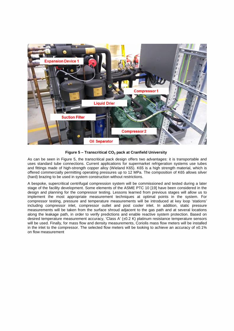
Figure 5 – Transcritical CO2 pack at Cranfield University
As can be seen in Figure 5, the transcritical pack design offers two advantages: it is transportable anduses standard tube connections. Current applications for supermarket refrigeration systems use tubesand fittings made of high-strength copper alloy (Wieland K65). K65 is a high strength material, which isoffered commercially permitting operating pressures up to 12 MPa. The composition of K65 allows silver(hard) brazing to be used in system construction without restrictions.
A bespoke, supercritical centrifugal compression system will be commissioned and tested during a laterstage of the facility development. Some elements of the ASME PTC 10 [19] have been considered in thedesign and planning for the compressor testing. Lessons learned from previous stages will allow us toimplement the most appropriate measurement techniques at optimal points in the system. Forcompressor testing, pressure and temperature measurements will be introduced at key loop ‘stations’including compressor inlet, compressor outlet and post cooler inlet. In addition, static pressuremeasurements will be taken from the surface shroud adjacent to the gas path and at several locationsalong the leakage path, in order to verify predictions and enable reactive system protection. Based ondesired temperature measurement accuracy, ‘Class A’ (±0.2 K) platinum resistance temperature sensorswill be used. Finally, for mass flow and density measurements, Coriolis mass flow meters will be installedin the inlet to the compressor. The selected flow meters will be looking to achieve an accuracy of ±0.1%on flow measurement

LESSONS LEARNED AND DISCUSSION
This project anticipated that reducing the level of technology risk currently associated with sCO2 wasteheat recovery implies three fundamental activities:
• Verifying claims of potential technology performance• Understanding cost of investment for a full research program• Identifying customers and supply chains for the exploitable output
We are in the process of addressing the first of these but, thus far, we have only partially addressed theother two. For the last two, we have not reached a point where further investment could be justified.However, our design and modelling of different cycles shows that there is commercial potential providingthat our assumptions and methods can be validated. This is all taking us in the right direction but thereare a number of milestones we need to hit before we can claim to have de-risked the business case.Recognizing this, alternative applications for supercritical CO2 (beyond WHR) are currently underassessment.
Some examples of lessons learned to-date include:
• Costing of key components is easier than costing of their auxiliary systems• Identifying an appropriate supply chain requires a systemic approach• The challenges of managing the procurement processes across industrial and academic
partners in a consortium are not trivial.
The following paragraphs discuss more specific lessons.
General operation of R744 systems
The following items are lesson learned from the design and pre-commissioning of the circulation loopwith transcritical compressors:
• If liquid can be trapped between valves, these sections of the system should include high-pressure protection; i.e.: pressure-relief valve (PRV)
• For CO2 leaks,o It is necessary to set system gas leak detection alarms levels
5,000 ppm for initial alarm (warning) 15,000 ppm for main alarm (evacuation)
o A large escape of CO2 in confined areas has the potential to kill• Dedicated lubricant system
o Polyolester (POE oil) lubricants are hygroscopic – harmful to aquatic lifeo Avoid exposure to airo Evacuate air and back-fill oil to the compressor under a vacuumo A crankcase heater so that the oil temperature is maintained within a specified range (to
reduce oil carry-over and R744 solubility)• Charging directly from the cylinder
o Prevent ice formation and thermal shock: charge gas (from cylinders) until the systempressure is slightly above the triple point (0.42 MPa)
o Slow process, need to allow the system to equalise (to avoid PRV discharge)o PRV lift would cause pressure decrease and loss of (wasted) CO2
o Efficiency of charging operation is dependent on the gas cylinder pressure and theambient temperature
• Relief of R744o Expansion of liquid R744 from any pressure level, and the expansion of gaseous R744
from pressure higher than 3.5 MPa, will lead to the formation of dry ice if the finalpressure is lower than about 0.52 MPa
o Avoid pipe lengths that could be plugged by dry ice formation (due to pressureexpansion)
o Pressure-relief valve: Select high-lift types to prevent dry ice blockage• Retrieving R744 directly from the pack

o Online recovery system (vessel & expansion regulator): risk of freezing• Elastomer seals
o When elastomer seals are depressurised, any absorbed R744 rapidly evaporates,causing explosive decompression and damage to the seal
• Running the system for the first timeo Do not attempt to charge an R744 system when the amount of refrigerant in the system
is unknowno Unlikely that all CO2 will be able to be charged into a system without running that
system firsto Make sure that there is no moisture in the system
• Storageo R744 should be stored in ventilated areaso Cylinders need to be stored below 50 °C
One observation that has arisen, that will be relevant to the specification of any future design of WHRmarine systems, is that ship engine room temperatures can exceed the critical point of CO2. Hence,even the low pressure side of a WHR system will need to be designed to withstand a pressure of 8 MPa(at system idle).
Modelling
Both Sandia National Laboratories and Knolls Atomic Power Laboratory started their CO2 projects withdeveloped simulation codes (RPC-SIM [13] and IST TRACE [14] respectively). Our project began withno available simulation tool and we needed to fast-track development of a simulation code to support theproject. PRO II was our chosen as the tool to develop and model steady-state cycle architecture anddesign point selection. In parallel, both steady-state and transient cycle modelling of the test rigarchitectures were performed using MATLAB Simulink®. Two sets of off-the-shelf libraries were used:Thermolib® and Simscape®. Currently, most of the performance calculations are being performed usingSimscape because it is able to incorporate ‘real gas’ effects. CO2 gas properties were calculated fromNIST miniREFPROP 9.1 [15] using the Span and Wagner equation of state [16].
The Span and Wagner equation of state is the approach that is routinely used by other researcherscurrently studying supercritical CO2. This approach works well provided that the flow domain remainsabove the saturation line. The flow cannot be modelled below the saturation line as some flowproperties, such as speed of sound are not defined. Hence, the sub-critical region was modelled as ametastable subcooled vapour. Metastable properties are based on direct extrapolation of the NISTREFPROP Span and Wagner equation of state model.
In the immediate vicinity of the critical point two issues are expected: Two-phase effects are expected tobecome more prominent as the limit of metastability is exceeded; and a singularity in the speed of soundoccurs.
Rolls-Royce has developed a CFD approach and code, using property tables, which allow the flow to bemodelled as a metastable gas when it becomes subcritical. Rolls-Royce refers to this model as “the realgas model”. Rolls-Royce real gas modelling comprises the Span and Wagner equation of stateimplemented in an internal code with the use of lookup tables which, for CO2, can be generated byREFPROP software (developed by NIST). REFPROP can be used to calculate metastable vapourproperties up to the Spinodal limit by extrapolation. This approach has yet to be validated by experimentbut does provide a method of generating thermodynamically consistent tables of properties forcompressibility factor, enthalpy and speed of sound as required by the internal code.
The Spalart-Allmaras turbulence model with wall functions [16] was used in all simulations. Viscous wallsurfaces were used for the impeller blades, hub and casing. Lower and upper periodic surfaces werealso used to reduce the size of the domain to a single blade and splitter pair.
Although the development of transient models for the first rig configuration is well advanced, modellingas a whole continues (noting that we consider that auxiliary systems require better characterization). Wealso intend to verify our Simscape models incorporating real data from different configurations, as andwhen such data is available from the rig.

The following lessons have been learned for modelling to-date:
• The effect of lubricant carry-over into the CO2 stream was not accounted during the top levelmodelling of the transcritical loop. This has an impact on performance and should be considered
• Potential pressure losses for operation near the critical point must be understood and managed– this is fundamental to the successful operation of the cycle / test rig
o Pressure drop correlations should be properly selected to cover off-design conditions• Assumptions for the thermal inertia of PCHEs has an important effect on calculating CO2
temperature changes near the critical point• Control of cooling water temperature becomes a critical factor to avoid CO2 condensation• Selection and characterization of control valves may prove to be inconsistent with CO2 ‘real gas’
effects; noting that variation of gas properties through the valve has not been assessed bysuppliers
Main Heat Exchanger
Heatric Printed Circuit (PCHE) technology is ideally suited to the recuperator duty in the supercriticalcarbon dioxide Brayton cycle [12], as this cycle requires a heat exchanger with good mechanicalintegrity and a high surface density; to achieve good thermal performance while remaining as compactas possible. The disadvantage of this technology is that it has not been optimised for recovering heatfrom the low pressure gas (or vapour) side of the heat exchanger when there is a high volumetric flow.Hence, this technology would not be economically viable for such applications.
Heatric also use Formed Plate Heat Exchanger (FPHE) technology, which is better suited to the lowerpressure gas in the exhaust of a gas turbine, but this technology does not currently achieve the samemechanical integrity as PCHE (noting that the high pressure side of a supercritical carbon dioxide powerconversion cycle can be greater than 200 Bar).
One technical solution to this challenge is to use a “hybrid” design, with a PCHE configuration for thehigh pressure CO2 and a FPHE configuration for the lower pressure gas turbine exhaust. This reducesthe back pressure on the gas turbine, reduces efficiency losses and reduces the overall size of the heatexchanger. The hybrid design therefore allows an economically viable solution for the Main HeatExchanger to be developed.
This project has allowed Heatric to develop this technology, previously considered for an intermediateheat exchanger in a Sodium Fast Breeder nuclear power plant, in a low risk environment.
Diffusion bonding is a complex and difficult process, especially when two different heat exchangegeometries need to be combined. Heatric have therefore developed new procedures and techniques forthe revised geometries, to facilitate the development of this hybrid technology for application in thisWaste Heat Recovery rig. Numerical tools were also developed and tested to produce three preliminarydesigns:
• Small scale hybrid (c. 140x180x105 mm)• Medium scale hybrid (c. 300x600x300 mm)• Large scale hybrid (c. 600X1500x600 mm)
Two of the three configurations were selected to be manufactured and mechanically tested. Differentcombinations of materials, fin specifications and bonding conditions were tried until a successful set ofparameters was identified that allowed a robust sample to be produced. This work has allowed Heatricto down-select a design and manufacturing methods for the MHEX and the MHEX has now beenreleased to manufacture.
COMPRESSOR DEVELOPMENT
Impeller
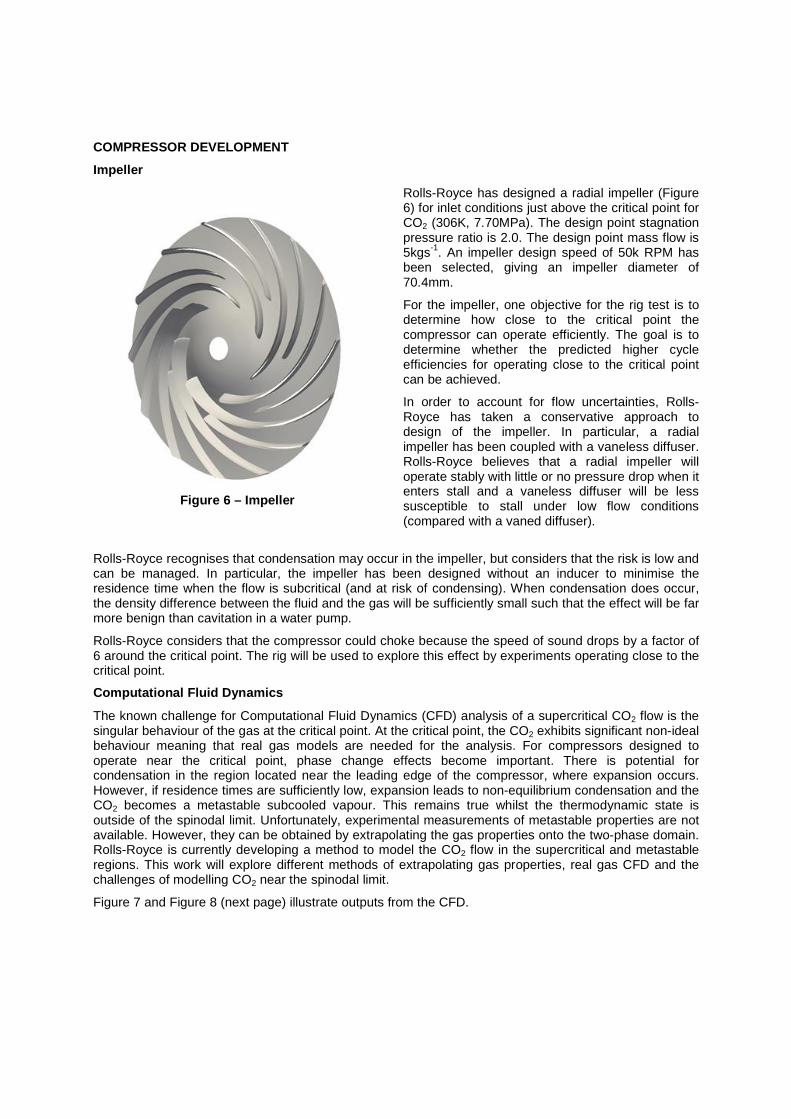
Figure 6 – Impeller
Rolls-Royce has designed a radial impeller (Figure6) for inlet conditions just above the critical point forCO2 (306K, 7.70MPa). The design point stagnationpressure ratio is 2.0. The design point mass flow is5kgs
-1. An impeller design speed of 50k RPM has
been selected, giving an impeller diameter of70.4mm.
For the impeller, one objective for the rig test is todetermine how close to the critical point thecompressor can operate efficiently. The goal is todetermine whether the predicted higher cycleefficiencies for operating close to the critical pointcan be achieved.
In order to account for flow uncertainties, Rolls-Royce has taken a conservative approach todesign of the impeller. In particular, a radialimpeller has been coupled with a vaneless diffuser.Rolls-Royce believes that a radial impeller willoperate stably with little or no pressure drop when itenters stall and a vaneless diffuser will be lesssusceptible to stall under low flow conditions(compared with a vaned diffuser).
Rolls-Royce recognises that condensation may occur in the impeller, but considers that the risk is low andcan be managed. In particular, the impeller has been designed without an inducer to minimise theresidence time when the flow is subcritical (and at risk of condensing). When condensation does occur,the density difference between the fluid and the gas will be sufficiently small such that the effect will be farmore benign than cavitation in a water pump.
Rolls-Royce considers that the compressor could choke because the speed of sound drops by a factor of6 around the critical point. The rig will be used to explore this effect by experiments operating close to thecritical point.
Computational Fluid Dynamics
The known challenge for Computational Fluid Dynamics (CFD) analysis of a supercritical CO2 flow is thesingular behaviour of the gas at the critical point. At the critical point, the CO2 exhibits significant non-idealbehaviour meaning that real gas models are needed for the analysis. For compressors designed tooperate near the critical point, phase change effects become important. There is potential forcondensation in the region located near the leading edge of the compressor, where expansion occurs.However, if residence times are sufficiently low, expansion leads to non-equilibrium condensation and theCO2 becomes a metastable subcooled vapour. This remains true whilst the thermodynamic state isoutside of the spinodal limit. Unfortunately, experimental measurements of metastable properties are notavailable. However, they can be obtained by extrapolating the gas properties onto the two-phase domain.Rolls-Royce is currently developing a method to model the CO2 flow in the supercritical and metastableregions. This work will explore different methods of extrapolating gas properties, real gas CFD and thechallenges of modelling CO2 near the spinodal limit.
Figure 7 and Figure 8 (next page) illustrate outputs from the CFD.

Figure 7 - Thermal properties of sCO2 under the ‘saturation dome’ extrapolated from the gasregion
Figure 9 (next page) illustrates the Rolls-Royce simulations steps on a T-S diagram. Results of asimulation are used as initial conditions for the next simulation. This ensures stability and enablessimulations closer to the critical point. Blue lines show the setup with theoretical calculations for efficiencyand purple lines show the boundary condition properties and efficiencies recalculated by CFD. The insetview on Figure 9 shows a scattered entropy plot obtained from a random 30000 points in the CFD domain(with red and blue indicating simulations for two different inlet conditions). This illustrates that, for inletconditions close to the critical point, some parts of the flow around the leading edge of the blade enter thetwo-phase region.
Figure 8 - Preliminary simulation results using the “real gas” model at inlet conditions of P = 7.7MPa, T = 691.2 K

Figure 9– Summary of Rolls-Royce CFD Simulations
Compressor Design
Figure 10 – Compressor development path
Figure 10 illustrates the development routetoward integrating the impeller into thecompressor. This is a work in progress buta design has been established that theconsortium has accepted can be developedfor integration into the test rig.
A number of compromises have beennecessary in order to identify the mostsuitable compressor for the rig and it hasbeen necessary to redefine the shaft seal.This became necessary as it was clear thatthe rate of gas leakage from the originaldesign would have been excessive. Wehave now engaged with a seal supplier tooptimise a seal for the compressor designand operating conditions.
The use of a single sided centrifugalimpeller means that there will be an axialload created by the pumped flow. Thedesign therefore includes features that willassure axial location of the impeller underall load conditions, whilst providingassurance that bearing limits are notexceeded.

Control System
Rolls-Royce is developing a control system for the test rig (Figure 11 – next page), which aims to controlthe system to ensure that (except for the compressor) CO2 is always supercritical and never enters thetwo phase region. As illustrated in Figure 12 (next page), the rig has been modelled in MATLAB, usingSimscape® libraries.
The model consists of two control inputs, expansion valve and cooling water valve, with the objective ofprecisely controlling the pressure and temperature of the CO2 entering the compressor. The expansionvalve is in the CO2 loop, controlling the back pressure through a valve area PID control mechanism.
The cooling water valve, in the cooling water loop, controls the amount of flow by PID control of the valvearea, controlling the temperature after the pre-cooler. The control mechanism is two SISO systems (onefor temperature and the other for pressure). Even though each input affects both outputs, this effect hasbeen ignored because pressure and temperature have very different system response times (slow andfast respectively). To design a robust control system, the plant architecture has been linearized to find therelationship between the individual inputs and outputs. With plant transfer functions obtained vialinearization, the controller was tuned to obtain stable characteristics and response behaviours.Ultimately, the controller will be connected to the rig using a Speedgoat target computer.
Figure 11– Rolls-Royce Control System
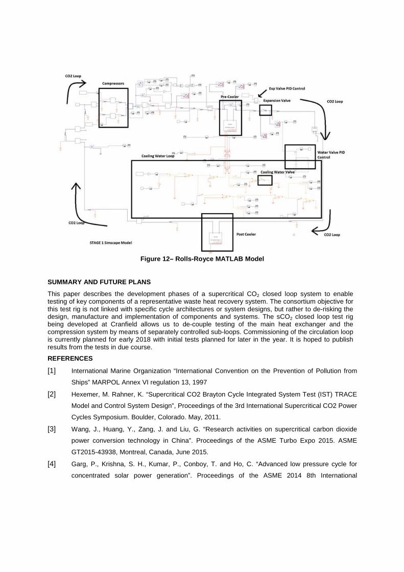
Figure 12– Rolls-Royce MATLAB Model
SUMMARY AND FUTURE PLANS
This paper describes the development phases of a supercritical CO2 closed loop system to enabletesting of key components of a representative waste heat recovery system. The consortium objective forthis test rig is not linked with specific cycle architectures or system designs, but rather to de-risking thedesign, manufacture and implementation of components and systems. The sCO2 closed loop test rigbeing developed at Cranfield allows us to de-couple testing of the main heat exchanger and thecompression system by means of separately controlled sub-loops. Commissioning of the circulation loopis currently planned for early 2018 with initial tests planned for later in the year. It is hoped to publishresults from the tests in due course.
REFERENCES
[1] International Marine Organization “International Convention on the Prevention of Pollution from
Ships” MARPOL Annex VI regulation 13, 1997
[2] Hexemer, M. Rahner, K. “Supercritical CO2 Brayton Cycle Integrated System Test (IST) TRACE
Model and Control System Design”, Proceedings of the 3rd International Supercritical CO2 Power
Cycles Symposium. Boulder, Colorado. May, 2011.
[3] Wang, J., Huang, Y., Zang, J. and Liu, G. “Research activities on supercritical carbon dioxide
power conversion technology in China”. Proceedings of the ASME Turbo Expo 2015. ASME
GT2015-43938, Montreal, Canada, June 2015.
[4] Garg, P., Krishna, S. H., Kumar, P., Conboy, T. and Ho, C. “Advanced low pressure cycle for
concentrated solar power generation”. Proceedings of the ASME 2014 8th International
Conference of Energy Sustainability, ES 2014 Collocated with the ASME 2012 12th International
Conference on Fuel Cell Science, Engineering and Technology. Volume 1: 30 June 2014.
[5] Vesely, L., Dostal, V. and Hajek, P. “Design of experimental loop with supercritical carbon
dioxide”. Proceedings of International Conference on Nuclear Engineering, ICONE. Volume 3:
Next Generation Reactors and Advanced Reactors; Nuclear Safety and Security. Czech
Republic, 7 July 2014.
[6] Hasuike, H., Yamamoto, T., Fukushima, T., Watanabe, T., Utamura, M. and Aritomi, M. “Test
plan and preliminary test results of a bench scale closed cycle gas turbine with supercritical
CO2”. Proceedings of the ASME Turbo Expo 2010. ASME GT2010-22171, Glasgow, UK, June
2010.
[7] Ahn, Y., Lee, J., Kim, S. G., Lee, J. I. and Cha, J. E. “The design study of supercritical carbon
dioxide integral experiment loop”. Proceedings of the ASME Turbo Expo 2013. ASME GT2013-
94122, San Antonio, USA, June 2013.
[8] Wright, S. A., Conboy, T. M., Parma, E. J., Lewis, T. G., Rochau, G. A. and Suo-Anttila, A. J.
“Summary of the Sandia Supercritical CO2 development program”. Proceedings of the 3rd
International Supercritical CO2 Power Cycles Symposium. Colorado, USA. 2011.
[9] Clementoni, E. M. and Cox, T. L. “Steady-state power operation of a supercritical carbon dioxide
Brayton cycle”. Proceedings of the 4th International Supercritical CO2 Power Cycles Symposium.
USA. 2014.
[10] Held, T. J. “Initial test results of a megawatt-class supercritical CO2 heat engine”. Proceedings of
the 4th International Supercritical CO2 Power Cycles Symposium. USA. 2014.
[11] Moore, J., Brun, K., Evans, N., Bueno, P. and Kalra, C. “Development of 1 MWe supercritical
CO2 Brayton cycle test loop” Proceedings of the 4th International Supercritical CO2 Power
Cycles Symposium. USA. 2014.
[12] Southall, D. and Dewson, S. J. “Innovative compact heat exchangers”. Proceedings of
International Congress on Advances in Nuclear Power Plants 2010, ICAPP 2010. 2010. p. 218–
226. ISBN 9781617386435.
[13] Wright, S., Sanchez,T. “Dynamic modelling and control of nuclear reactors coupled to close-loop
Brayton cycle systems using SIMULINK”. American Institute of Physics, Volume 746, 2005
[14] Hexemer, M.J.,Hoang,H.T., Rahner, K.D.,Siebert, B.W., and Wahl. G.D. “Integrated Systems
Test (IST) S-CO2 Brayton Loop Transient Model Description and Initial Results”, Proceedings of
the 2nd International Supercritical CO2 Power Cycles Symposium. Troy, NY, USA. April, 2009.
[15] Lemmon, E.W., Huber, M.L. and McLinden, M.O. “NIST Reference Fluid Thermodynamic and
Transport Properties miniREFPROP”. National Institute of Standards and Technology. 9.1.
Gaithersburg, USA, 2013.
[16] Span, R. and Wagner, W. “A new equation of state for carbon dioxide covering the fluid region
from the triple-point temperature to 1100 K at pressures up to 800 MPa”. J. Phys. Chem. Ref.
Data. 1996. Vol. 25, no. 6, p. 1509–1596.
[17] Spalart, P. and Allmaras, S. “A one-equation turbulence model for aerodynamic flows”.
Proceedings of the 30th Aerospace Sciences Meeting and Exhibit. USA. 1992.
[18] American Society of Mechanical Engineers (ASME) (2000), Performance Test Code for Single
Phase Heat Exchangers, ASME PTC 12.5-2000
[19] American Society of Mechanical Engineers (ASME) (1997), Performance Test Code on
Compressors and Exhausters, ASME PTC 10-1997
ACKNOWLEDGEMENTS
This research has received funding from Innovate UK under project reference 101982. The authors aregrateful to Rolls-Royce plc and Heatric Division of Meggitt UK Ltd for its support during the project. Theauthors would like to thank Robert Collins, Mark Hassan, Anmol Manohar, Joseph Palmer, PawelSafuryn and Russel Limbrick for their input into this research effort.
LIST OF SYMBOLS
FHPE Formed plate heat exchangersGT Gas triangleIMO International Maritime OrganizationMHEX Main heat exchangerNIST National Institute of Standard and TechnologyPCHE Printed circuit heat exchangersPR Pressure ratioPRV Pressure relief valveTRL Technology readiness level
Meet the authors
Working for the research project called: Supercritical CO2 Waste HeatRecovery for Marine Gas Turbines, which has received funding fromInnovate UK under project reference 101982. It comprises a consortiumof three partners: Rolls-Royce plc (lead participant), Meggitt (UK)Limited and Cranfield University.
Dr Eduardo Anselmi is a Research Fellow in the Propulsion EngineeringCentre at Cranfield University, where he coordinates the test activitiesfor supercritical CO2 equipment. For the Innovate UK funded consortia,he has been developing a test rig of a representative waste heatrecovery system. Eduardo is a Production Engineer with eight years’experience in the oil and gas industry, and six years as an engineeringlecturer. He has completed a PhD in Aerospace Engineering, an MSc inMechanical Engineering and number of specialised courses in Oil &Gas.
Ian Bunce MSc CEng is a Research Engineer in the Rolls-Royce FutureTechnologies Group. He is the designated project manager for theInnovate UK funded consortia developing a supercritical CO2 test rig todemonstrate the feasibility for waste heat recovery. Ian is anexperienced nuclear engineer with a diverse background in compactpressurised water reactor power plant. He has experience of componentdesign, procurement, in-service support, project management, technicaldocumentation, research and development. Innovation is a strong traitthrough all of Ian’s experience; he has been involved in a number oftechnical innovations for nuclear plant on Submarines and has raised anumber of patents.
Professor Vassilios Pachidis is the Director of the Rolls-Royce UniversityTechnology Centre for Aero Systems Design Integration & Performanceat Cranfield University. He also heads the Gas Turbine EngineeringGroup within the Propulsion Engineering Centre. He is the PrincipalInvestigator of the Innovate UK funded consortia. He holds a MEng fromThe University of Liverpool and an MSc and a PhD from Cranfield. Hismain research focus is on gas turbine performance and certification,novel cycles, turbomachinery experimental, analytical and computationalaerodynamics, propulsion system integration and environmentalperformance.
Dr Pavlos Zachos is appointed as Lecturer in TurbomachineryAerodynamics within the Propulsion Engineering Centre at CranfieldUniversity. Pavlos has conducted assessments of multiple candidatetechnologies for waste heat recovery system for marine applications.
Before joining Cranfield, he worked within the Aerothermal Methodsgroup at Rolls-Royce plc in Derby as a designer of turbine internalcooling passages and heat transfer optimisation for the Trent enginefamily. He was awarded a doctorate in Gas Turbine Sub-idlePerformance, Altitude Relight and Windmilling in 2010.
Michael Johnston MEng CEng is a chemical engineer specialising incompact heat exchanger development. Michael currently works for theHeatric division of Meggitt designing Printed Circuit Heat Exchangers.He has also worked designing and developing heat exchangertechnologies for use in aircraft engines whilst working for Meggitt ControlSystems.
For the past 3 years Michael has been developing new heat exchangertechnologies for use within a supercritical CO2 waste heat recoverysystem as part of the Innovate UK funded consortia. Michael has aMEng in Chemical Engineering and has assisted with process modellingand safety reviews of the test rig as part of this project.