Embed Size (px)
Citation preview

1
An Overview of Electric and Advanced Propulsion Activities in Japan *†
Haruki Takegahara ‡
Tokyo Metropolitan Institute of Technology, Dept. of Aerospace Eng. Asahigaoka 6, Hino, Tokyo 191-0065, JAPAN
+81-42-585-8659, [email protected]
IEPC-01-004
∗ Presented as Paper IEPC-01-000 at the 27th International Electric Propulsion Conference, Pasadena, CA, 15-19 October, 2001. † Copyright 2001 by the Electric Rocket Propulsion Society. All rights reserved. ‡ Professor, Senior Member AIAA
This paper describes the current status of electric propulsion technology development and related studies in Japan. Ion engine systems (IES) onboard the Engineering Test Satellite VI (ETS-VI) and the Communications and Broadcasting Engineering Test Satellite (COMETS), and a quasisteady MPD thruster onboard the Space Flyer Unit (SFU) were successfully demonstrated. The National Space Development Agency of Japan (NASDA) is to launch an improved IES onboard the Engineering Test Satellite VIII (ETS-VIII) in 2003. 1.8 kW/ 250 mN-class hydrazine DC arcjet thrusters are to be used on the Data Relay Test Satellite (DRTS). The Institute of Space and Astronautical Science (ISAS) is developing the sample and return space mission from an asteroid, the MUSES-C, which is scheduled to be launched in 2002 and to bring back some specimens to the Earth in 2007 from an extra-terrestrial object. In the MUSES-C mission, a cathode-less microwave discharge ion engine system is ready as a primary propulsion in the interplanetary space. Electric propulsion studies at universities, research institutes and industries are also aiming at applications as well as fundamental physics.
Flight Plans And Results National Space Development Agency of JAPAN (NASDA) NASDA has now three satellite projects on-boarding electric propulsions, those EPs are all for north-south station keeping of the satellites on the geostationary orbit. First of all, Engineering Test Satellite VIII (ETS- VIII) equipped with the ion engine system (IES), which is developed on the base of the IES on ETS-VI and Communications and Broadcasting Engineering Test Satellite (COMETS). Because of the difference of the satellite weight, the most significant alteration is mission time required to increase to 16,000 hours from 6,500 hours, that of ETS-VI. Also to improve the reliability and to reduce the cost, some changes are made on a power processing unit and a propellant managing unit, and gimbaling mechanisms equipped
to lessen a thrusting misalignment. The launch of ETS- VIII is scheduled in 2003. Secondly, Data Relay Test Satellite (DRTS) adopted the arcjet system, which is imported from General Dynamics, USA. AJ system is modified for several DRTS requirements from the original MR-509 of General Dynamics. Major differences are an input voltage and thrust. The former is changed to 31 - 51.5 V, and the latter is that west thrusters are changed 15 % larger than east ones in thrust. DRTS will be launched in 2002. The following satellite with EP is Ultra-High-Data-Rate Internet Test Satellite, which is planned to launch in 2005. This project is just started, so that no details are defined, however IES system may be quite similar to that of ETS-VIII.

2
Institute of Space and Astronautical Science (ISAS) A 10-cm class microwave IES (Ion Engine System) is under development in ISAS to meet requirements for an asteroid sample return mission which will be launched next year and return to Earth in 2007. [1] The scheduled launch date is November - December 2002 toward the most probable target asteroid "1998SF36" (spectrum-type undefined) for the time being with its aphelion distance of 1.693 AU, perihelion distance of 0.955 AU, the eccentricity of 0.279 and the inclination of 1.713 degrees. The launch vehicle is an ISAS proprietary rocket M-V and will be launched from Kagoshima Space Center at Uchinoura, the southernmost part of the Kyushu island, Japan. The target asteroid was selected from the Near-Earth asteroids rather than the main-belt ones because the former selection affords our small launch capability. This mission was designated as MUSES-C (Mu Space Engineering Spacecraft - C) following after the MUSES-B, VSOP mission in 1997 and MUSES-A, Lunar swing-by mission in 1990. The MUSES-C spacecraft will be launched as 512 kg by M-V launch vehicle (Figure 1). According to the meaning of engineering satellite, the major purpose of MUSES-C is to verify 4 key-technologies as the path-finder mission for future interplanetary explorations of ISAS: (1) Electric propulsion application, (2) Highly autonomous control, optical navigation and guidance, (3) Sampler mechanism, (4) Direct Earth reentry from interplanetary space.
Fig. 1 MUSES-C spacecraft drawing. From the lifetime and high specific impulse higher than 2,500 s requirements to electric propulsion, we employed a new technology of microwave discharge, in principle the ECR (Electron Cyclotron Resonance) ion source and neutralizer (Figure 2). [2] Both ion source and neutralizer are excited by a single
microwave amplifier with the frequency of 4.25 GHz which is divided into the ion source and the neutralizer by a coupler box. This concept is therefore a completely electrodeless system in order to avoid life limitation caused by electrode erosion and degradation which have been frequently discussed especially in cathodes. An 18,000 hour endurance test for an engineering model was already finished in 1999, [3] and a prototype model was manufactured to be tested through a series of environment tests for qualification and is undergoing a second time endurance test from April 2000. The flight model design was already finalized based upon the prototype model thrust performances and integration specifications. Now almost all the flight models were combined each other to check out their mutual interfaces as well as bus interfaces. This microwave IES architecture constitutes 4 ITRs (Ion Thruster) consisting of ITHs (Ion Thruster Head) and NEUTs (Neutralizer) on a radiation panel with a bi-axially movable gimbal mechanism, 4 MSUs (Microwave Supplying Unit) , 3 IPPUs (IES Power Processing Unit) for acceleration power management, and 1 PMU (Propellant Management Unit). Besides microwave employment for both ion source and neutralizer, in this IES another remarkable feature is 3-grid system of Carbon-Carbon composite. As summarized in Table 1, the MUSES-C mission requires the IES to generate thrust of about 24 mN for maximum power input of 1,158 W by 3 of the
Fig. 2 Simultaneous operation of 2 ion thrusters inside a vacuum chamber.
3
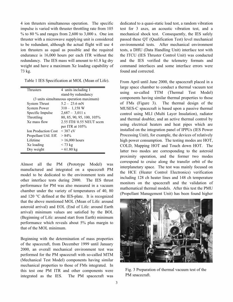
4 ion thrusters simultaneous operation. The specific impulse is varied with thruster throttling rate from 105 % to 80 % and ranges from 2,600 to 3,000 s. One ion thruster with a microwave supplying unit is considered to be redundant, although the actual flight will use 4 ion thrusters as equal as possible and the required endurance is 16,000 hours per each ITR without the redundancy. The IES mass will amount to 61.8 kg dry weight and have a maximum Xe loading capability of 73 kg.
Table 1 IES Specification at MOL (Mean of Life).
Thrusters 4 units including 1
stand-by redundancy (3 units simultaneous operation maximum)
System Thrust 5.2 – 23.6 mN System Power 310 – 1,158 W Specific Impulse 2,687 – 3,011 s Throttling 80, 85, 90, 95, 100, 105% Xe mass flow 2.55 ITH/ 0.55 NEUT sccm per ITR at 105% Ion Production Cost < 387 eV Propellant Util. Eff. > 84% Lifetime > 16,000 hours Xe loading < 73 kg Dry weight = 61.80 kg
Almost all the PM (Prototype Model) was manufactured and integrated on a spacecraft PM model to be dedicated to the environment tests and other interface tests during 2000. The IES thrust performance for PM was also measured in a vacuum chamber under the variety of temperatures of 40, 80 and 120 °C defined at the IES-plate. It is recognized that the above mentioned MOL (Mean of Life: around asteroid arrival) and EOL (End of Life: around Earth arrival) minimum values are satisfied by the BOL (Beginning of Life: around start from Earth) minimum performance which reveals about 5% plus margin to that of the MOL minimum. Beginning with the determination of mass properties of the spacecraft, from December 1999 until January 2000, an overall mechanical environment test was performed for the PM spacecraft with so-called MTM (Mechanical Test Model) components having similar mechanical properties to those of FMs integrated. In this test one PM ITR and other components were integrated as the IES. The PM spacecraft was
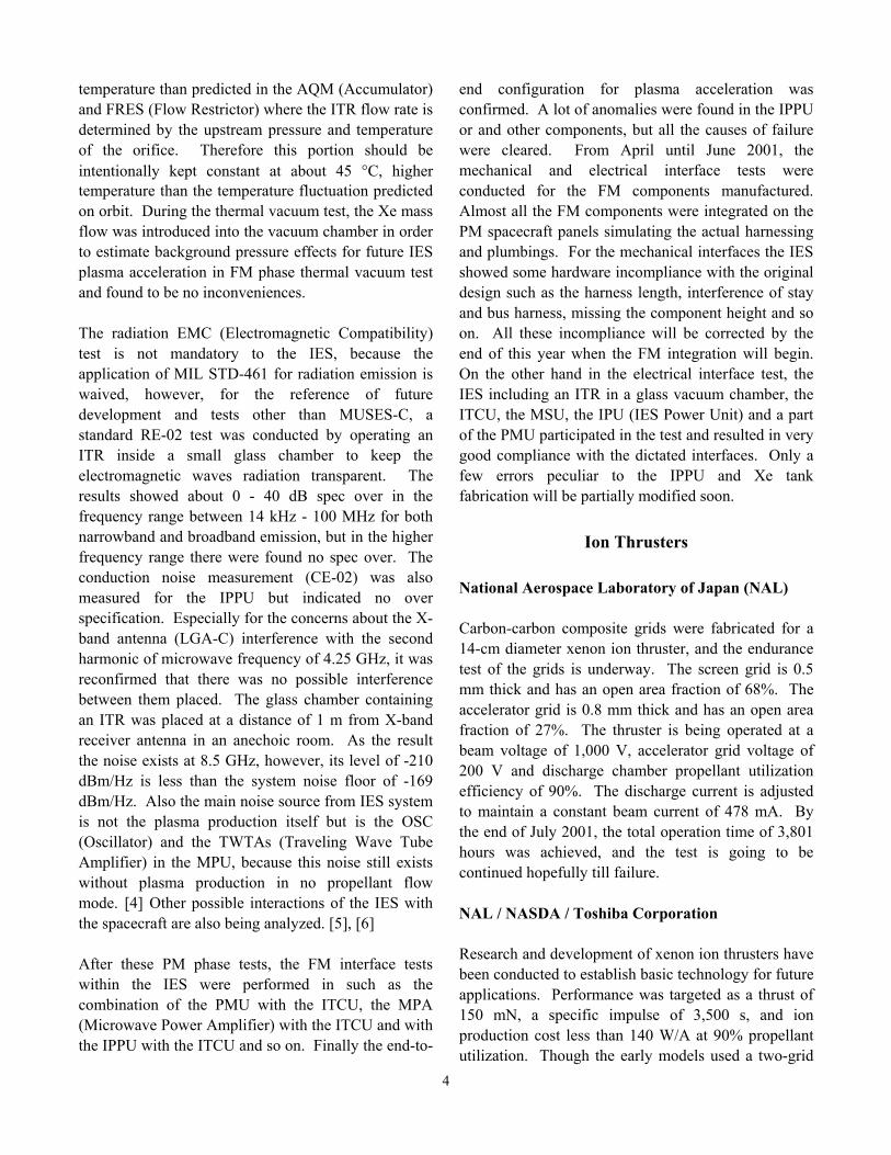
dedicated to a quasi-static load test, a random vibration test for 3 axes, an acoustic vibration test, and a mechanical shock test. Consequently, the IES safely passed these QT (Qualification Test) level mechanical environmental tests. After mechanical environment tests, a DHU (Data Handling Unit) interface test with the ITCU (IES Thruster Control Unit) was conducted and the IES verified the telemetry formats and command interfaces and some interface errors were found and corrected. From April until June 2000, the spacecraft placed in a large space chamber to conduct a thermal vacuum test using so-called TTM (Thermal Test Model) components having similar thermal properties to those of FMs (Figure 3). The thermal design of the MUSES-C spacecraft is based upon a passive thermal control using MLI (Multi Layer Insulation), radiator and thermal doubler, and an active thermal control by using electrical heaters and heat pipes which are installed on the integration panel of IPPUs (IES Power Processing Unit), for example, the devices of relatively high power consumption. The testing modes are HOT, COLD, Mapping HOT and Touch down HOT. The latter two modes are corresponding to the asteroid proximity operation, and the former two modes correspond to cruise along the transfer orbit of the interplanetary space. The test was mainly focused on the HCE (Heater Control Electronics) verification including 128 ch heater lines and 148 ch temperature monitors on the spacecraft and the validation of mathematical thermal models. After this test the PMU (Propellant Management Unit) has been found higher
Fig. 3 Preparation of thermal vacuum test of the PM spacecraft.
4
temperature than predicted in the AQM (Accumulator) and FRES (Flow Restrictor) where the ITR flow rate is determined by the upstream pressure and temperature of the orifice. Therefore this portion should be intentionally kept constant at about 45 °C, higher temperature than the temperature fluctuation predicted on orbit. During the thermal vacuum test, the Xe mass flow was introduced into the vacuum chamber in order to estimate background pressure effects for future IES plasma acceleration in FM phase thermal vacuum test and found to be no inconveniences. The radiation EMC (Electromagnetic Compatibility) test is not mandatory to the IES, because the application of MIL STD-461 for radiation emission is waived, however, for the reference of future development and tests other than MUSES-C, a standard RE-02 test was conducted by operating an ITR inside a small glass chamber to keep the electromagnetic waves radiation transparent. The results showed about 0 - 40 dB spec over in the frequency range between 14 kHz - 100 MHz for both narrowband and broadband emission, but in the higher frequency range there were found no spec over. The conduction noise measurement (CE-02) was also measured for the IPPU but indicated no over specification. Especially for the concerns about the X-band antenna (LGA-C) interference with the second harmonic of microwave frequency of 4.25 GHz, it was reconfirmed that there was no possible interference between them placed. The glass chamber containing an ITR was placed at a distance of 1 m from X-band receiver antenna in an anechoic room. As the result the noise exists at 8.5 GHz, however, its level of -210 dBm/Hz is less than the system noise floor of -169 dBm/Hz. Also the main noise source from IES system is not the plasma production itself but is the OSC (Oscillator) and the TWTAs (Traveling Wave Tube Amplifier) in the MPU, because this noise still exists without plasma production in no propellant flow mode. [4] Other possible interactions of the IES with the spacecraft are also being analyzed. [5], [6] After these PM phase tests, the FM interface tests within the IES were performed in such as the combination of the PMU with the ITCU, the MPA (Microwave Power Amplifier) with the ITCU and with the IPPU with the ITCU and so on. Finally the end-to-
end configuration for plasma acceleration was confirmed. A lot of anomalies were found in the IPPU or and other components, but all the causes of failure were cleared. From April until June 2001, the mechanical and electrical interface tests were conducted for the FM components manufactured. Almost all the FM components were integrated on the PM spacecraft panels simulating the actual harnessing and plumbings. For the mechanical interfaces the IES showed some hardware incompliance with the original design such as the harness length, interference of stay and bus harness, missing the component height and so on. All these incompliance will be corrected by the end of this year when the FM integration will begin. On the other hand in the electrical interface test, the IES including an ITR in a glass vacuum chamber, the ITCU, the MSU, the IPU (IES Power Unit) and a part of the PMU participated in the test and resulted in very good compliance with the dictated interfaces. Only a few errors peculiar to the IPPU and Xe tank fabrication will be partially modified soon.
Ion Thrusters National Aerospace Laboratory of Japan (NAL) Carbon-carbon composite grids were fabricated for a 14-cm diameter xenon ion thruster, and the endurance test of the grids is underway. The screen grid is 0.5 mm thick and has an open area fraction of 68%. The accelerator grid is 0.8 mm thick and has an open area fraction of 27%. The thruster is being operated at a beam voltage of 1,000 V, accelerator grid voltage of 200 V and discharge chamber propellant utilization efficiency of 90%. The discharge current is adjusted to maintain a constant beam current of 478 mA. By the end of July 2001, the total operation time of 3,801 hours was achieved, and the test is going to be continued hopefully till failure. NAL / NASDA / Toshiba Corporation Research and development of xenon ion thrusters have been conducted to establish basic technology for future applications. Performance was targeted as a thrust of 150 mN, a specific impulse of 3,500 s, and ion production cost less than 140 W/A at 90% propellant utilization. Though the early models used a two-grid

5
system of 30-cm diameter, the late models used a three-grid system of 35-cm diameter for longer life and thrust margin (Fig. 4). These improvements gave the thruster performance equal to or better than the targets, with the ion production cost as low as 104 W/A. [7] The latest improvement was conducted for endurance. Then, an endurance test targeting 5,000-hour thrusting was conducted to seek the erosion aspects, particularly, of the grids. [8] The thrusting time reached 4,994 hours on April 1st, 2001, and the test was terminated although the thruster could be operated longer. The thruster was disassembled for inspection, and masses of the grids were measured to evaluate the grid erosion. Erosion and cracks were found in some of the thruster parts, indicating that design improvements in these parts are necessary to meet the tentative lifetime target of 30,000 hours.
Fig. 4 NAL / NASDA / Toshiba BBM-2 thruster.
Mitsubishi Electric Corporation (MELCO) The Ion Engine Subsystem for NSSK on ETS-VIII is now being developed at MELCO under the contract with NASDA. The main design parameter of the IES is shown in Table 2. After the performance of the component has been verified in each development test, the interface verification test and EMC test of the subsystem are now carrying on.
Table 2 Main design parameter
Thrust Method Average Thrust from BOL to EOL Average Isp from BOL to EOL Weight Total Impulse Total Operation Time Total Number of Firing
Kaufman-type xenon ion thrusters Over 20 mN Over 2,200 s 95 kg 1.15 × 10⁶ Ns 16,000 hours (with average thrust of 20 mN) 3,000 cycles
ISAS Development of a 25 mN class microwave discharge ion thruster A 20-cm-diam. 25 mN class microwave discharge ion thruster for spacecraft propulsion was designed and fabricated. The new thruster will be powered by the microwave of up to 100 W, which is introduced from a microwave power source via coaxial cable followed by a coaxial to waveguide transformer. Inside the discharge chamber, permanent magnets realize electron cyclotron resonance (ECR) discharge and corresponding easy ignition and efficient plasma production. From this ion source, a beam extraction system consisting of flat, 20-cm-diam. for effective ion beam diameter Carbon/Carbon composite grids can extract above 450 mA ion beam, and initial performance test results of up to 760 W showed a thrust of 21 mN, which showed a possibility of 25 mN class microwave ion thruster for a total electrical power of 1 kW.

6
Research on new microwave launching methods of plasma generators for ion thruster applications The next generation of microwave ion thrusters may be supplied with microwave power through antennas inserted into the discharge chambers directly without circular waveguides. This method has been already used in the microwave discharge neutralizers for MUSES-C mission, and will also make the ion sources more compact and lighter. A demonstration was conducted by using a 6-cm-diam. chamber with an L-type antenna surrounded by two magnet rings. An ion current of 120 mA was extracted at a microwave power of 50 W. Microwave reflection was completely suppressed using a commercial coaxial 3-stub tuner inserted into the feed line. In the near future, the circular waveguide of 25 mN class microwave ion thruster will be replaced with such a compact and versatile launching system. NEC Corporation NEC has been developing the MUSES-C Ion Engine System (IES) in collaboration with ISAS. Ion Thruster (ITR), Thruster Control Unit (ITCU) and Power Processing Unit (IPPU) are manufactured in house. Toward the launch in 2002, IES system functional test is now undergoing. For an interplanetary mission, the IES has some features such as autonomous onboard thruster control, thrust vector control and wide range power throttle according to the change of spacecraft power generation. To accomplish an autonomous thruster control, the ITCU cooperates with a satellite data-handling unit (DHU). For thrust vector control, Attitude and orbit control unit (AOCU) automatically operates a gimbal mechanism (IPM) in order to unload angular momentum of reaction wheels. Each of the ITR is able to change its power consumption and thrust in the range of 65 to 100%. In combination with number of operating thruster (1 to 3), the IES total power consumption is controlled between 300 to 1200 W and 4 to 23 mN of thrust. Mitsubishi Heavy Industories (MHI) MHI is developing the propellant management unit (PMU) of the MUSES-C spacecraft ion engine system, as shown in Fig. 5, in collaboration with ISAS and
NEC. A pulse width modulation regulator system is applied for the PMU.
Fig. 5 Schematic Block Diagram of PMU of the MUSES-C ion engine system.
University of Tokyo An efficient code that can estimate the lifetime of an ion thruster due to charge-exchange was developed. With this tool, it is possible to gain knowledge about the ion thruster lifetime, and it enables the design of ion thrusters in shorter periods and at a lower cost. In the case of a three dimensional grid system, the grid erosion is concentrated on the inside wall region of the hole, and an axisymmetric approach can be adopted as well (Fig. 6). For the 2 grid system, the erosion pattern is three dimensional, and this requires an analysis using the three dimensional code. However, using the information obtained from the two dimensional code and introducing the emission surface model reduces the computational cost.
Fig. 6 Ion Extraction features with change in grid shape ( MUSES-C grid system ).

7
The analytical and computational results indicate that the thruster lifetime imposed by charge exchange erosion can be modeled in a very simple form. The dependence of lifetime on ion beam density is very strong both in the 3-grid and 2-grid systems. Especially for the 3-grid system, the lifetime is in inverse proportion to the 4th power of beam current density (with a fixed propellant utilization efficiency). Tokyo Metropolitan Institute of Technology (TMIT) Experimental/Analytical Study on Ion Beam Extraction Phenomena The transient phenomena of ion beam extraction immediately after applying beam-accelerating voltage in an ion thruster were investigated by means of an experimental and computational approach for the detailed evaluation of plasma sheath condition. [9],[10] In the numerical simulation, a Particle-in-Cell method is adopted and electrons are treated as particles as well as ions to investigate the plasma boundary (ion sheath) phenomena in detail. In the experiments, the properties of discharge chamber plasma of the 14-cm diam. cusped ion thruster and the time-scale of the beam-accelerating voltage application were evaluated. The calculation results [11] graphically explained the formation process of an ion sheath and a beamlet in transition in addition to the erosion mechanism of an accelerator grid by transient ion impingement. As a result it was found that the beam extraction capability varies drastically depended on radial distance from the thruster center, accelerating voltage and the thickness of screen grid. Each phenomenon was discussed using the ion sheath boundary variation obtained from the particle simulation result.(Fig. 7) Study on Plasma Contactor using Hollow Cathode for Electrodynamic Tether Moreover, the evaluation of electromagnetic tether system using the hollow cathode have been carrying on. To understand the contacting process with plasma enables various applications of electrodynamic tether system such as orbit raising, deorbit, station keeping and power generator. In this study, a hollow cathode was used as a plasma contactor for both electron emitter and collector. The results show the simultaneous operation of the plasma contactors in the simulated plasma environment and the closed current
loop formation via ambient plasma between the emitter and the collector was confirmed. [12]
t = 0.075 s
t = 0.250 s
t = 0.500 s
t = 0.750 s
t = 1.000 s
Fig. 7 Spatial distribution of ion particle at each elapsed time.
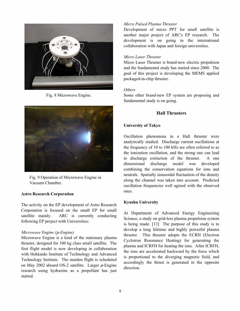
Kyushu University At Department of Aeronautics and Astronautics, the structure of a plume exhausted from an ion engine of the MUSES-C spacecraft is being numerically analyzed by applying DSMC to neutral particles and PIC to ions. The working gas considered here is Xe and charge exchange reactions between neutral and ion particles is included in the analysis. Especially, this study is focused on the behavior of the charge-exchange (CEX) ions which strike the surface of the ion engine to give damage on it. Furthermore, the interactions of plumes from three ion engines are being revealed. Hokkaido Institute of Technology Based on a new concept, a low power electrostatic thruster is being developed for its application to 50 kg class satellite, which is named “Microwave Engine”. The proto-model (PM) of the microwave engine was manufactured and the qualification test (QT) was conducted. The estimated performances are 1250 s in specific impulse, 0.36 mN in thrust and 10 % in thrust efficiency when it is operated at 26.6 W.
8
Fig. 8 Microwave Engine.
Fig. 9 Operation of Microwave Engine in Vacuum Chamber.
Astro Research Corporation The activity on the EP development of Astro Research Corporation is focused on the small EP for small satellite mainly. ARC is currently conducting following EP project with Universities: Microwave Engine (µ-Engine) Microwave Engine is a kind of the stationary plasma thruster, designed for 100 kg class small satellite. The first flight model is now developing in collaboration with Hokkaido Institute of Technology and Advanced Technology Institute. The maiden flight is scheduled on May 2002 aboard OS-2 satellite. Larger µ-Engine research using hydrazine as a propellant has just started.
Micro Pulsed Plasma Thruster Development of micro PPT for small satellite is another major project of ARC's EP research. The development is on going in the international collaboration with Japan and foreign universities. Micro Laser Thruster Micro Laser Thruster is brand-new electric propulsion and the fundamental study has started since 2000. The goal of this project is developing the MEMS applied packaged-in-chip thruster. Others Some other brand-new EP system are proposing and fundamental study is on going.
Hall Thrusters University of Tokyo Oscillation phenomena in a Hall thruster were analytically studied. Discharge current oscillations at the frequency of 10 to 100 kHz are often referred to as the ionization oscillation, and the strong one can lead to discharge extinction of the thruster. A one dimensional discharge model was developed combining the conservation equations for ions and neutrals. Spatially sinusoidal fluctuation of the density along the channel was taken into account. Predicted oscillation frequencies well agreed with the observed ones. Kyushu University At Department of Advanced Energy Engineering Science, a study on grid-less plasma propulsion system is being made. [13] The purpose of this study is to develop a long lifetime and highly powerful plasma thruster. This thruster adopts the ECRH (Electron Cyclotron Resonance Heating) for generating the plasma and ICRFH for heating the ions. After ICRFH, the ions are accelerated backward by the force which is proportional to the diverging magnetic field, and accordingly the thrust is generated in the opposite direction.
9
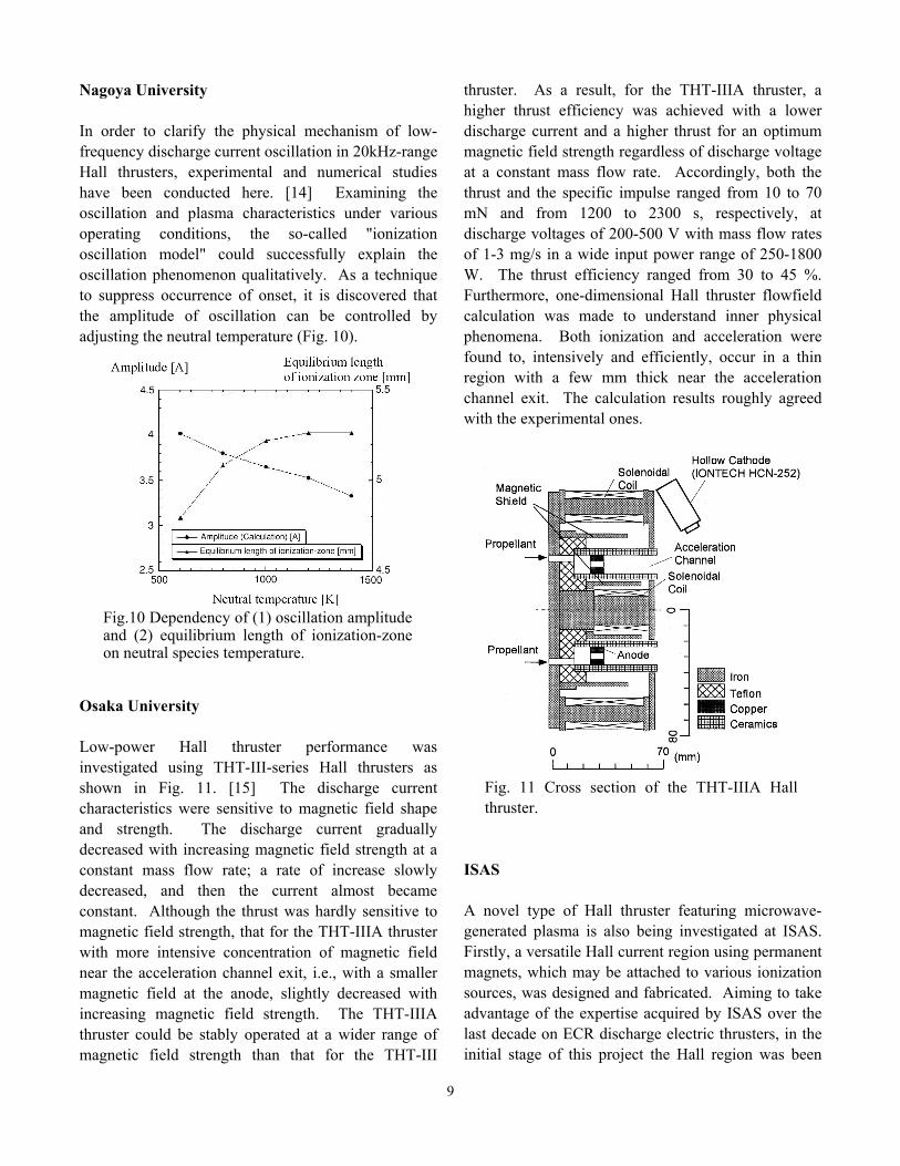
Nagoya University In order to clarify the physical mechanism of low-frequency discharge current oscillation in 20kHz-range Hall thrusters, experimental and numerical studies have been conducted here. [14] Examining the oscillation and plasma characteristics under various operating conditions, the so-called "ionization oscillation model" could successfully explain the oscillation phenomenon qualitatively. As a technique to suppress occurrence of onset, it is discovered that the amplitude of oscillation can be controlled by adjusting the neutral temperature (Fig. 10).
Osaka University Low-power Hall thruster performance was investigated using THT-III-series Hall thrusters as shown in Fig. 11. [15] The discharge current characteristics were sensitive to magnetic field shape and strength. The discharge current gradually decreased with increasing magnetic field strength at a constant mass flow rate; a rate of increase slowly decreased, and then the current almost became constant. Although the thrust was hardly sensitive to magnetic field strength, that for the THT-IIIA thruster with more intensive concentration of magnetic field near the acceleration channel exit, i.e., with a smaller magnetic field at the anode, slightly decreased with increasing magnetic field strength. The THT-IIIA thruster could be stably operated at a wider range of magnetic field strength than that for the THT-III
thruster. As a result, for the THT-IIIA thruster, a higher thrust efficiency was achieved with a lower discharge current and a higher thrust for an optimum magnetic field strength regardless of discharge voltage at a constant mass flow rate. Accordingly, both the thrust and the specific impulse ranged from 10 to 70 mN and from 1200 to 2300 s, respectively, at discharge voltages of 200-500 V with mass flow rates of 1-3 mg/s in a wide input power range of 250-1800 W. The thrust efficiency ranged from 30 to 45 %. Furthermore, one-dimensional Hall thruster flowfield calculation was made to understand inner physical phenomena. Both ionization and acceleration were found to, intensively and efficiently, occur in a thin region with a few mm thick near the acceleration channel exit. The calculation results roughly agreed with the experimental ones.
Fig. 11 Cross section of the THT-IIIA Hall thruster.
ISAS A novel type of Hall thruster featuring microwave-generated plasma is also being investigated at ISAS. Firstly, a versatile Hall current region using permanent magnets, which may be attached to various ionization sources, was designed and fabricated. Aiming to take advantage of the expertise acquired by ISAS over the last decade on ECR discharge electric thrusters, in the initial stage of this project the Hall region was been
Fig.10 Dependency of (1) oscillation amplitudeand (2) equilibrium length of ionization-zoneon neutral species temperature.
10
attached to the downstream part of the so-called Yoshino-I ECR ionization stage. Experimental results indicate that the plasma density obtained with this ECR device reached a maximum of 3x1011 cm-3, slightly below the critical density threshold value dictated by the 4.25 GHz microwave frequency device utilized in this experiment. From these findings, it has been concluded that a higher density plasma source was more appropriate for optimum interaction once the plasma enters the Hall current region. To this respect, a microwave cavity producing plasma densities up to 1x1013 cm-3 has been recently tested and adopted for use as the plasma source in the new Hall thruster configuration. At the present time, a microwave cavity discharge chamber of proper dimensions is being designed in order to accommodate the attachment of a Hall current channel. The new configuration will surely produce a higher density plasma and effectively remove undesirable magnetic field interactions present in the ECR device initially tested.
Arcjets, MPD Thrusters and Pulsed Plasma
Thrusters Mitsubishi Electric Corporation (MELCO) A 1.8 kW class hydrazine DC arcjet will be used for NSSK on Data Relay Test Satellite(DRTS), which is under development at MELCO under the contract with NASDA. Flight model components were manufactured by General Dynamic Space Propulsion Systems, USA, and they have been installed on the spacecraft by MELCO. ISAS Limited Life Test of DC Arcjet Anodes [16] Anode degradation is still a severe problem for low power arcjets, and so far, only a few kW-class arcjets achieved a lifetime of 1,000-hour. One of the degradation mechanisms of the DC arcjet will be explained by grain embrittlement of the anode in a recrystalization process; after the anode material is heated up, a crystal grows up to a large grain, and correspondingly weak grain boundaries will appear. As an attempt to improve the anode strength by
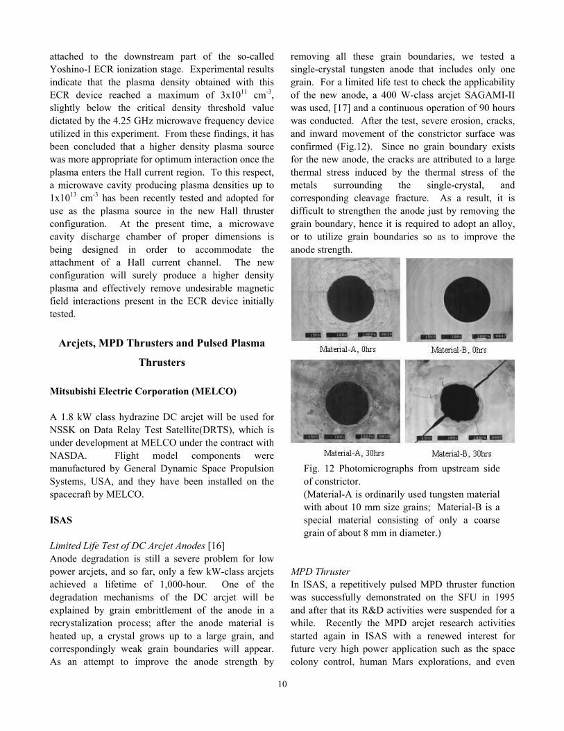
removing all these grain boundaries, we tested a single-crystal tungsten anode that includes only one grain. For a limited life test to check the applicability of the new anode, a 400 W-class arcjet SAGAMI-II was used, [17] and a continuous operation of 90 hours was conducted. After the test, severe erosion, cracks, and inward movement of the constrictor surface was confirmed (Fig.12). Since no grain boundary exists for the new anode, the cracks are attributed to a large thermal stress induced by the thermal stress of the metals surrounding the single-crystal, and corresponding cleavage fracture. As a result, it is difficult to strengthen the anode just by removing the grain boundary, hence it is required to adopt an alloy, or to utilize grain boundaries so as to improve the anode strength.
Fig. 12 Photomicrographs from upstream side of constrictor. (Material-A is ordinarily used tungsten material with about 10 mm size grains; Material-B is a special material consisting of only a coarse grain of about 8 mm in diameter.)
MPD Thruster In ISAS, a repetitively pulsed MPD thruster function was successfully demonstrated on the SFU in 1995 and after that its R&D activities were suspended for a while. Recently the MPD arcjet research activities started again in ISAS with a renewed interest for future very high power application such as the space colony control, human Mars explorations, and even

11
SPSS (Solar Power Space Station) transportation. This R&D approach usually needs a large facility requirement on the ground to supply 100 kW or up to 1 MW electricity and the relevant vacuum pumping system to maintain good background pressure lower than 10 mPa that will prevent unfavorable propellant inhalation of "entrainment". Instead of beginning with high power MPD arcjets it will be better choice to design a low power steady state MPD arcjet with applied filed or to promote a repetitive pulsed MPD arcjet more high power, however the latter is limited by the weight of capacitors and coils in the pulse forming network with the charging control unit if it is clustered, therefore an upper limit is imposed on the high power evolution. The former is a challenging choice because low power steady state MPD arcjet is sparse and the basic design has not yet fully established. The applied field is requisite and its configuration and the electrodes design to maintain a stable arc discharge will be the key technology. The ISAS MPD group will restart both types of MPD arcjets for low power design but envisioning high power evolution in the future by a cluster design of multi discharge chambers, because an exclusive facility for high power MPD is not realistic at this time. The future clustered MPD at high power should be designed based upon thermal analyses and electrode erosion estimates. Pulsed Plasma Thruster A PPT study also started from 2000 in ISAS under the joint research program with TMIT. A 20-J energy per pulse is targeted for future micro- or nano- satellite applications. The propellant survey other than PTFE and the precision improvement of the thrust stand are the main themes of research. In 2000 a trigger and a capacitor charging unit as the electrical power source for the laboratory experiments were procured and some film capacitors candidates commercially available are tested in a vacuum chamber to confirm the compatibility to vacuum condition with respect to outgassing. And some kind of solid propellants were surveyed for trade-off study envisioning future long-term storage and relatively massive supply of the propellant.
Osaka University Low Power Arcjet Thruster Development The laboratory-model radiation-cooled arcjet thruster RAT-VII, as shown in Fig. 13, was operated in a low electric power range of 400-800 W with a mixture of hydrogen and nitrogen simulating hydrazine at a wide mass flow rate range of 20-50 mg/s, although the arcjet geometry had already been designed optimally for 1 kW class operation. [18] In cases with large mass flow rates above 35 mg/s, the thrusts and the thrust efficiencies were above 110 mN and 34 %, respectively, although the specific impulses were below 390 s. The thruster performance evaluated was much higher even at 500 W than those for monopropellant hydrazine thrusters. Unsteady thermal analyses of the thruster body were conducted using electrode heat losses empirically derived. The temperature distributions calculated for the RAT-VII body with room-temperature propellant injection showed that the body temperatures at 1000 W rapidly increased just after the arc ignition and approached some values around 1000 K after about 30 min. However, in a low power of 500 W, a long time of about 60 min was spent on achievement of a thermal steady-state condition with lower body temperatures. For the RAT-VII thruster, operations at 500 W are not preferable to those at 1000 W from the standpoint of thruster performance, thermal characteristic and operational stability in the early stage from the arc ignition up to a steady-state operation. A 70 %-downsize body for the RAT-VII thruster was designed. The time up to a thermal steady-state operation at 500 W was shorter with the 70 %-downsize thruster than with the RAT-VII thruster, and the body temperatures were higher. In the RAT-VII thruster with high-temperature propellant injection, the time to a steady-state condition at 500 W was also shorter than that with room-temperature propellant injection. However, it is feared that the structure near the inlet of the high-temperature gas may be destroyed by an excessive heat stress generated by contact between the gas and the cold body part just after the arc ignition. Therefore, downsizing the RAT-VII body is better around 500 W. A newly-designed 500 W-class arcjet thruster is under operation.
12
Fig.13 Cross section of the radiation-cooled arcjet thruster RAT-VII.
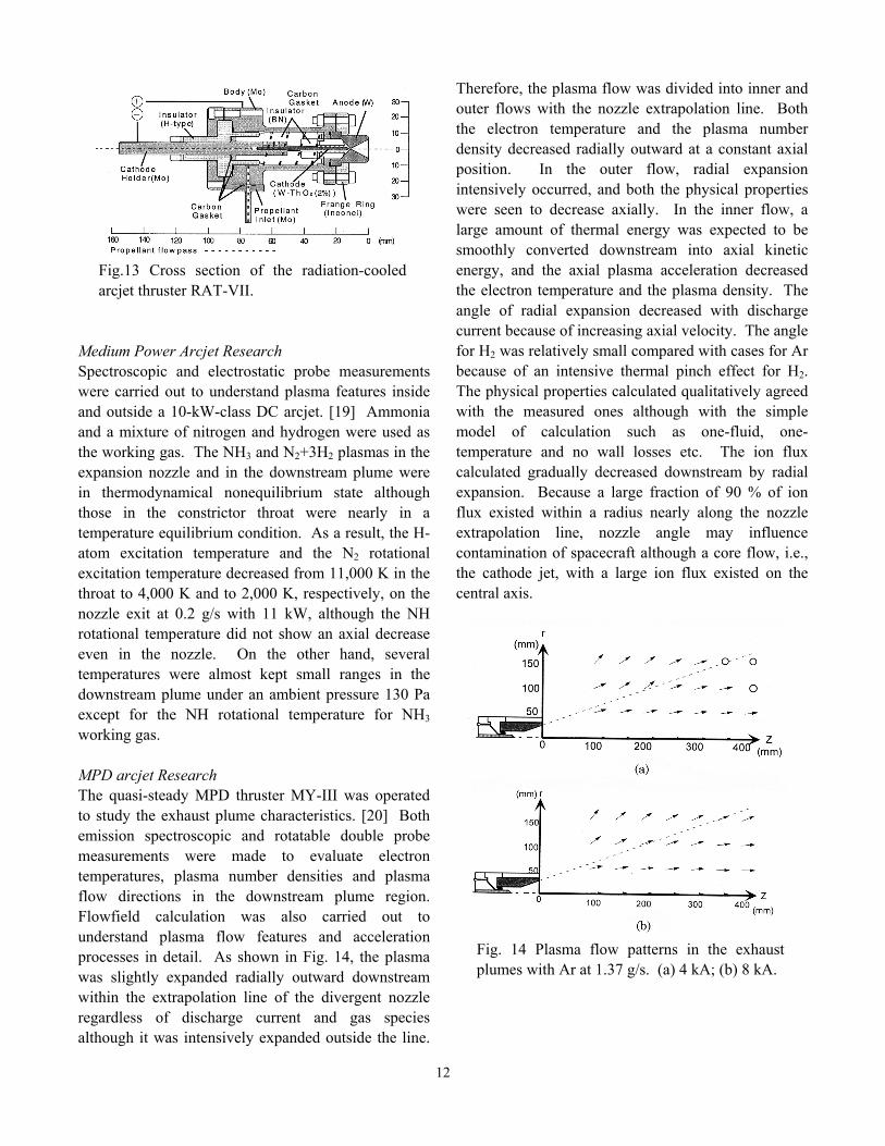
Medium Power Arcjet Research Spectroscopic and electrostatic probe measurements were carried out to understand plasma features inside and outside a 10-kW-class DC arcjet. [19] Ammonia and a mixture of nitrogen and hydrogen were used as the working gas. The NH3 and N2+3H2 plasmas in the expansion nozzle and in the downstream plume were in thermodynamical nonequilibrium state although those in the constrictor throat were nearly in a temperature equilibrium condition. As a result, the H-atom excitation temperature and the N2 rotational excitation temperature decreased from 11,000 K in the throat to 4,000 K and to 2,000 K, respectively, on the nozzle exit at 0.2 g/s with 11 kW, although the NH rotational temperature did not show an axial decrease even in the nozzle. On the other hand, several temperatures were almost kept small ranges in the downstream plume under an ambient pressure 130 Pa except for the NH rotational temperature for NH3 working gas. MPD arcjet Research The quasi-steady MPD thruster MY-III was operated to study the exhaust plume characteristics. [20] Both emission spectroscopic and rotatable double probe measurements were made to evaluate electron temperatures, plasma number densities and plasma flow directions in the downstream plume region. Flowfield calculation was also carried out to understand plasma flow features and acceleration processes in detail. As shown in Fig. 14, the plasma was slightly expanded radially outward downstream within the extrapolation line of the divergent nozzle regardless of discharge current and gas species although it was intensively expanded outside the line.
Therefore, the plasma flow was divided into inner and outer flows with the nozzle extrapolation line. Both the electron temperature and the plasma number density decreased radially outward at a constant axial position. In the outer flow, radial expansion intensively occurred, and both the physical properties were seen to decrease axially. In the inner flow, a large amount of thermal energy was expected to be smoothly converted downstream into axial kinetic energy, and the axial plasma acceleration decreased the electron temperature and the plasma density. The angle of radial expansion decreased with discharge current because of increasing axial velocity. The angle for H2 was relatively small compared with cases for Ar because of an intensive thermal pinch effect for H2. The physical properties calculated qualitatively agreed with the measured ones although with the simple model of calculation such as one-fluid, one-temperature and no wall losses etc. The ion flux calculated gradually decreased downstream by radial expansion. Because a large fraction of 90 % of ion flux existed within a radius nearly along the nozzle extrapolation line, nozzle angle may influence contamination of spacecraft although a core flow, i.e., the cathode jet, with a large ion flux existed on the central axis.
Fig. 14 Plasma flow patterns in the exhaust plumes with Ar at 1.37 g/s. (a) 4 kA; (b) 8 kA.

13
Nagoya University Numerical analyses of unsteady one-dimensional flows in an MPD thruster have been carried out, [21], [22] including (1) non-equilibrium ionization / recombination processes of propellant gas and (2) velocity slip between charged and neutral particles. Calculated two-fluid results show that the velocity of charged particles is noticeably different from that of neutral particles in the downstream of inlet, and higher than the mean velocity calculated by one-fluid model, while the electron temperature is much lower than the temperature from one-fluid model. These differences help improve the current distribution in Segment 1 (in Fig. 15). Thus, in conclusion, non-equilibrium ionization / recombination processes must be included in an attempt to analyze realistic MPD flows.
Tohoku University At Department of electrical engineering in Tohoku university is being investigated a high power MPD arcjet (typically 200 V, 10 kA) with an externally-applied axial magnetic field of 0.1T in the HITOP device. [23] Spatial distributions of ion temperature, axial and rotational flow velocities are measured by spectroscopy at the muzzle region of the MPD. Helium ion temperature increases from 20 eV near the muzzle to more than 50 eV at several-cm downstream region. [24] An expanding magnetic nozzle is utilized to increase Mach number of the plasma flow. Mach number is almost unity near the muzzle region and increases up to 3 by passing through the magnetic nozzle, resulting in a quasi-steady supersonic plasma
flow. A Hall accelerator is also being developed as a low-voltage, high-current ion-beam source. Tokyo Metropolitan Institute of Technology (TMIT) TMIT has started the R&D of 2 J class PPT with the collaboration of NASDA. Following the first generation Teflon PPT such as ETS-IV PPE, its R&D for the application to NASDA’s µ-Lab Sat II (50 kg) as the experimental equipment for the evaluation of attitude control and de-orbit maneuver has been conducting. Its present BBM status of the R&D, system / components test review including PPU (Power Processing Unit) and Capacitor Bank and the results of the successive firing test over 500,000 shots (H-MST: Half Million Shot Test) are presented in another paper. [25],[26] Figure 16 shows the photo of the H-MST.
Fig. 16 Photo of TMIT PPT Half Million Shot Test.
Kyushu Institute of Technology Two different types of Teflon propellant thrusters are being experimentally examined. One is known well as a pulsed plasma thruster, PPT, whereas its operation is tried with Teflon including chemically reactive substances and by different electrical discharge methods such as double successive pulses and prolonged duration. The other is a one Newton class continuous operation thruster, which operation is controlled by arc discharges that induce forced
Fig. 15 Comparison between calculated (ontwo models) and experimental currentfractions.
experiment one-fluid model two-fluid model
Segment number
Current fraction [%]
14
combustion to non-combustion self sustainable chemical rocket propellants. Through such modifications, we are aiming at utilization of additional chemical energy and/or more efficient conversion of electrical energy to higher motor performances. Mitsubishi Heavy Industories (MHI) MHI has been developing a 300 W class hydrazine arc-jet propulsion system, considering application to near future space programs, in collaboration with ISAS and NASDA. The arc-jet thruster was run with N2+3H2, which was substituted for hydrazine decomposed product in actual state. Main configurations and characteristics of the arc-jet thruster are as follows: Nozzle throat diameter: 0.3 mm, Cathode gap: 0 mm, Thrust: 59 – 74 mN (nominal 64 mN) Input power: 370 W (at nominal thrust) The on-off test of 1600 cycles, with a repetitive condition of 15 s firing and 15 s radiation cooling, was conducted. Specific impulse levels of 430 to 450 s were kept stably during the endurance test, as shown in Fig. 17. The test results show that the durability and stability of the thruster in the long-term operation was demonstrated. Moreover, MHI start developing a pulsed plasma thruster (PPT) system for a micro satellite.
Fig. 17 Specific impulse characteristics of a 500 W class arcjet thruster in 1,600 cycle endurance operation.
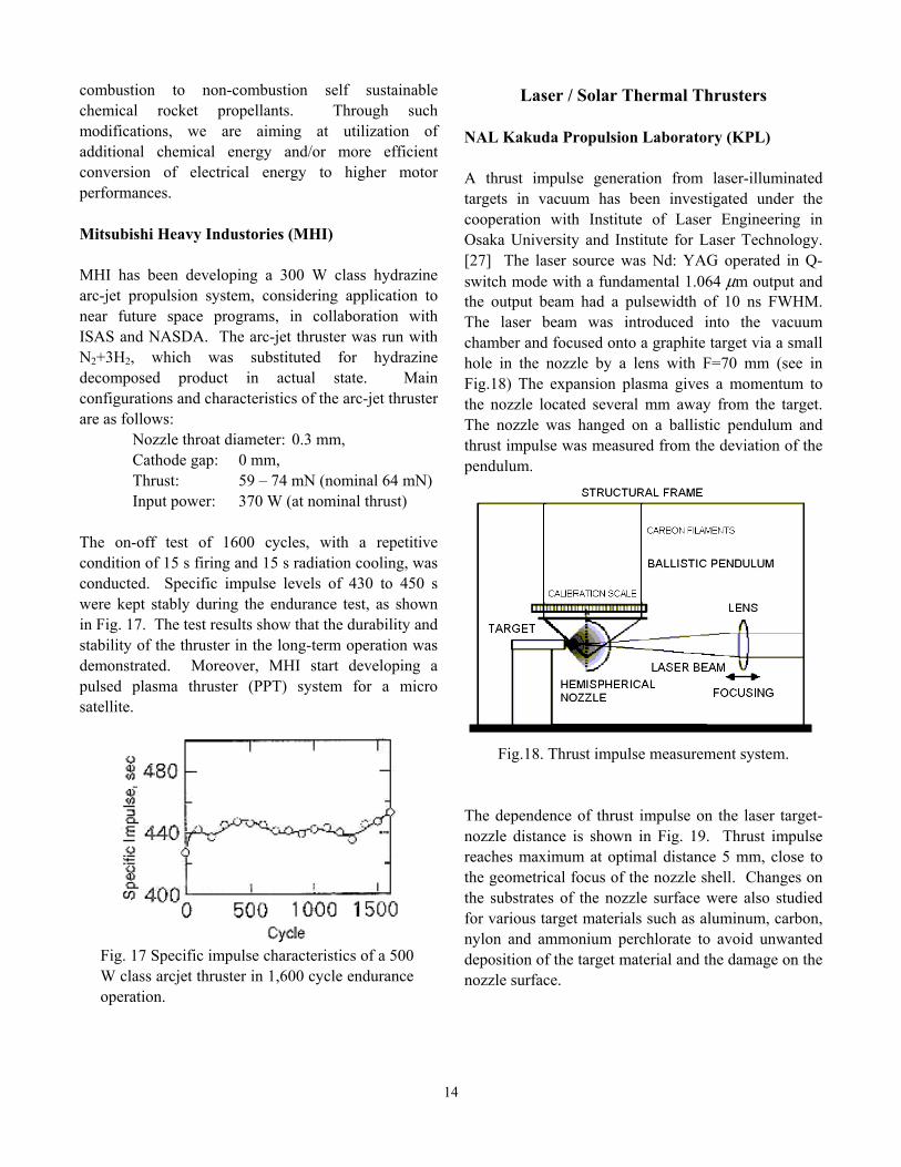
Laser / Solar Thermal Thrusters NAL Kakuda Propulsion Laboratory (KPL) A thrust impulse generation from laser-illuminated targets in vacuum has been investigated under the cooperation with Institute of Laser Engineering in Osaka University and Institute for Laser Technology. [27] The laser source was Nd: YAG operated in Q-switch mode with a fundamental 1.064 µm output and the output beam had a pulsewidth of 10 ns FWHM. The laser beam was introduced into the vacuum chamber and focused onto a graphite target via a small hole in the nozzle by a lens with F=70 mm (see in Fig.18) The expansion plasma gives a momentum to the nozzle located several mm away from the target. The nozzle was hanged on a ballistic pendulum and thrust impulse was measured from the deviation of the pendulum.
Fig.18. Thrust impulse measurement system.
The dependence of thrust impulse on the laser target-nozzle distance is shown in Fig. 19. Thrust impulse reaches maximum at optimal distance 5 mm, close to the geometrical focus of the nozzle shell. Changes on the substrates of the nozzle surface were also studied for various target materials such as aluminum, carbon, nylon and ammonium perchlorate to avoid unwanted deposition of the target material and the damage on the nozzle surface.

15
Fig. 19 The dependence of the momentum transfer into the nozzle on the laser target-nozzle distance.
University of Tokyo A laser thermal thruster powered by a CW CO2 laser was developed to examine basic characteristics of laser propulsion. It consists of a ZnSe condensing lens, ZnSe window, stainless steel chamber and tungsten throat. Thrust is measured by a load cell, and the heat loss to the chamber wall is evaluated by measuring the heat flux to the cooling water. Figure 20 shows energy transmission distribution of input laser power. Numerical simulation is also conducted, and the results would be presented during this conference.
Fig. 20 Energy transmission distribution. Laser power: 700 W, propellant: argon.
Tohoku University At Institute of Fluid Science, experimental study of the laser-driven in-tube accelerator is being conducted. [28], [29] In this device, a projectile is accelerated in an acceleration tube, in which the propellant gas is filled. The species and fill pressure of the propellant are controllable parameters. Using xenon, a momentum coupling coefficient of 290 N/WM is achieved; a 2.2-gram projectile can be vertically launched at a fill pressure of 0.3 MPa and an input laser power of 68 W. Tokai University Relativistic Plasma Acceleration by Intense Laser Pulses for Space Propulsion A feasibility study of the utilization of laser plasma accelerators for space propulsion was conducted. [30], [31] The utilization of the extremely high gradients associated with laser-induced plasma waves for the next generation of high energy linear particle accelerators was suggested more than a decade ago [32], and since then there have been fruitful discussion and theoretical results. [30]-[34] In recent years, there has been a tremendous progress in experimental accomplishment mainly due to the advances in the development of compact tera-watt laser systems capable of exciting plasma waves with gradients as high as several tens of GeV/m, which is approximately three orders of magnitude greater than that generated by the conventional radio frequency linear accelerators (RF linacs) that have an intrinsic limitation due to electrical breakdown on material surface. [32]-[36] The Reflective Plasma Acceleration (Fig.21(a)), in which the laser pulse is irradiated onto the target surface and in a short duration the plasma is induced on the target surface and accelerated against the incident laser pulse, is well-known. [37]-[41] However, there has been growing recognition of the Penetrative Plasma Acceleration (Fig.21(b)), in which the laser pulse is irradiated on the thin-foil target surface and in a short duration the plasma is induced on the reverse side and accelerated parallel to the incident laser pulse. [31], [42]-[45] In the latter case, large numbers of electrons tend to be accelerated along the beam direction through the ponderomotive force of
16
the incident laser pulse, inducing a local and temporary increase of positive ion density on the irradiated point. Then, Coulomb explosion occurs and those positive ions are accelerated through Coulomb forces among those ions and/or with those previously emitted electrons. Maximum ion energy of order several MeV through the acceleration was reported in previous papers. [45] Assuming a proton accelerated up to 1 MeV, its speed corresponds to 3 ~ 4 % of the speed of light and the specific impulse Isp of order 106 s. In this study, the fundamental investigation of the penetrative ion acceleration for space propulsion was performed. As a preliminary study, observation and propulsive performance tests for both penetrative and reflective plasma accelerations with low-power laser pulses irradiated on various targets were conducted. [31]
(a) Reflective Acceleration (b) Penetrative Acceleration Fig. 21 Plasma acceleration ((a)Reflective Acceleration and (b)Penetrative Acceleration) through a solid target with high power laser irradiation.
Solar Thermal Propulsion in NAL NAL started a preliminary STP investigation several years ago. Cooperated with the National Research Institute of Metals [46], NAL has conducted preliminary experiments for heating and injecting in STP thrusters made of single crystal molybdenum (SC-Mo) or single crystal tungsten (SC-W) with 8 mm, 20 mm, 40 mm and 65 mm in outer diameter. Using a 1.6m-diameter precise paraboloidal concentrator in NAL, the nitrogen and helium propellant temperature reached about 2,300 K, that is, over 800 s Isp for hydrogen propellant [47]-[50]. On the other hand, a thin polyester film with aluminum vapor deposition was adopted for an ultra-light
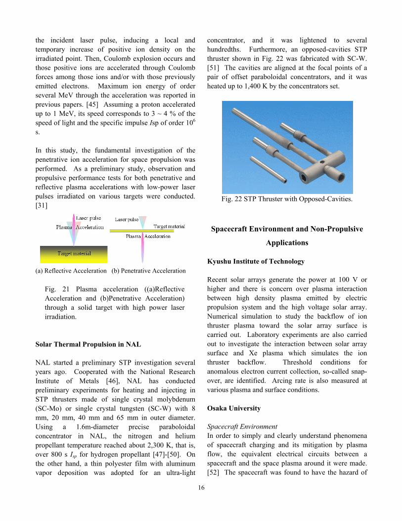
concentrator, and it was lightened to several hundredths. Furthermore, an opposed-cavities STP thruster shown in Fig. 22 was fabricated with SC-W. [51] The cavities are aligned at the focal points of a pair of offset paraboloidal concentrators, and it was heated up to 1,400 K by the concentrators set.
Fig. 22 STP Thruster with Opposed-Cavities. Spacecraft Environment and Non-Propulsive
Applications Kyushu Institute of Technology Recent solar arrays generate the power at 100 V or higher and there is concern over plasma interaction between high density plasma emitted by electric propulsion system and the high voltage solar array. Numerical simulation to study the backflow of ion thruster plasma toward the solar array surface is carried out. Laboratory experiments are also carried out to investigate the interaction between solar array surface and Xe plasma which simulates the ion thruster backflow. Threshold conditions for anomalous electron current collection, so-called snap-over, are identified. Arcing rate is also measured at various plasma and surface conditions. Osaka University Spacecraft Environment In order to simply and clearly understand phenomena of spacecraft charging and its mitigation by plasma flow, the equivalent electrical circuits between a spacecraft and the space plasma around it were made. [52] The spacecraft was found to have the hazard of

17
electrical breakdown between the spacecraft conductive main body and the insulating surface during the mitigation. In the space plasma simulator, the segmented ion collector in series with negatively charged condensers was exposed to argon plasma flows with changing plasma velocity under a constant plasma number density. The time variations of neutralization current and ion sheath shape were measured. The mitigation process was expected to depend on plasma velocity and plasma number density, i.e., ion velocity and ion flux, and their dependence intensively changed with the attack angle of plasma flow to the negatively charged surface by effect of inertia of ions. In cases that a negatively-charged insulating surface disappears from a plasma source, in the shade on view from a plasma source, i.e., at wake condition, particularly with a high plasma velocity, electrical breakdown fears occurring by a large difference in mitigation time between the absolute charging of the spacecraft conductive main body and the local charging of the insulating surface. Non-Propulsive Applications •Ceramic Coatings Using MPD Arcjets For applications of MPD arcjets to ceramic coatings, two types of MPD arcjet generators were developed. [53] One was provided with a cathode covered with Mullite or Zirconia ceramics and the other with a titanium cathode. The former was operated with Ar for Mullite or Zirconia coating due to ablation of the cathode cover and the latter with N2 for titanium nitride spray coating due to reactive process between ablated titanium particles and nitrogen plasma. Uniform dense coatings 30 and 10 µm in thickness for Mullite and Zirconia, respectively, were sprayed with 110-shot operations and 40 µm for titanium nitride with 50-shot operation. Mullite coatings with above 1000 Vickers hardness were deposited. TiN, Ti2N and Ti mixed layers for titanium nitride spraying were observed, and their contents depended on titanium-cathode diameter. The hardness of the titanium nitride coatings increased with increasing cathode diameter although the thickness decreased from 40 to 3 µm. •Nitriding of Metals by Irradiation of Supersonic Hydrogen/Nitrogen-Mixture and Ammonia Plasmajets Supersonic reactive plasmajets under a low pressure environment were utilized for nitriding of metal
surfaces. [54] Supersonic pure N2 plasmajets were proved to be reactive enough to construct hard titanium nitride layers on the titanium surfaces by a few minutes plasmajet irradiation even at a processing chamber pressure of 30 Pa. Furthermore, nitriding of titanium plates and atmospheric thermal sprayed titanium coatings were carried out at 30 Pa using supersonic H2/N2-mixture or ammonia plasmajets. As a result, it was found that the nitriding of the surfaces was enhanced by hydrogen addition to nitrogen plasmajets or by using NH3 plasmajets.
Acknowledgements The author is deeply indebted to the colleagues who provided the updated information on electric propulsion research/development activities of each organizations.
References [1] Nishiyama, K., Shimizu, Y., Funaki, I., Kuninaka, H. and Toki, K., "Measurement of the Electromagnetic Emission from the MUSES-C Ion Engine System," 27th International Electric Propulsion Conference (IEPC), Pasadena California, IEPC-01-112, October15-19, 2001. [2] Nishida, M., Hyakutake, T., Kuninaka H. and Toki, K., "DSMC-PIC Analysis of a Plume from a Small Ion Engine," 27th IEPC, Pasadena California, IEPC-01-110, October15-19, 2001. [3] Kuninaka, H., Funaki, I., Nishiyama K. and Molina-Morales, P., "Virtual Anode Phenomena Due to Lack of Neutralization on Ion Thrusters Based on MUSES-C Program," 37th AIAA/ASME/SAE/ASEE Joint Propulsion Confernece & Exhibit (JPC), Salt Lake City, Utah, AIAA 2001-3785, July 8-11, 2001. [4] Funaki, I. and Kuninaka, H., "Overdense Plasma Production in a Low-power Microwave Discharge Electron Source," Japanese Journal of Applied Physics, 40, 2001, pp. 2495-2500. [5] Kuninaka, H., Funaki, I., Nishiyama K., Shimizu, Y. and Toki, K., "Result of 18,000-hour Endurance Test on Microwave Discharge Ion Thruster Engineering Model," 36th AIAA/ASME/SAE/ASEE JPC, Huntsville Alabama, AIAA 2000-3276, July 16-19, 2000.
18
[6] Toki, K., Kuninaka, H., Funaki, I., Nishiyama, K. and Shimizu, Y., "Development of a Microwave Ion Engine System EM for MUSES-C Mission," 22nd International Symposium on Space Technology and Science (ISTS), Morioka Japan, ISTS 2000-b-09, May 28-June 4, 2000. [7] Kitamura, S., Miyazaki, K., Hayakawa, Y., Nakao, M., Kajiwara, K., Yoshida, H. and Akai, K., "Research and Development Status of 150-mN Xenon Ion Thrusters," IAF-00-S.4.06, 2000. [8] Hayakawa, Y., Kitamura, S., Yoshida, H., Yamamoto, Y., Akai, K. and Maeda, T., "5000-hour Endurance Test of a 35-cm Xenon Ion Thruster," 37th JPC, AIAA-2001-3492, 2001. [9] Okawa, Y. and Takegahara, H., "Particle Simulation on Ion Beam Extraction Phenomena in an Ion Thruster," 26th IEPC, Kitakyushu, Japan, IEPC-99-146, 1999. [10] Okawa, Y., Satow, H. and Takegahara, H., "Investigation of Ion Beam Extraction Phenomena Using a Particle Simulation Code," ISTS-2000-b-37p, 2000. [11] Okawa, Y., Takegahara, H. and Tachibana, T., "Numerical Analysis of Ion Beam Extraction Phenomena in an Ion Thruster," 27th IEPC, Pasadena, USA, IEPC01-97, 2001. [12] Kozakai, M. and Takegahara, H., "Evaluation of Plasma Contactor Ground Experiments for Electrodynamic Tether," 27th IEPC, Pasadena, USA, IEPC01-242, 2001. [13] Y. Mori, et al., Trans. Fusion Technol., 39, 195-198, 2001. [14] Furukawa, T., Miyasaka, T. and Fujiwara, T., "Methods of Controlling Low-Frequency Oscillation in a Hall Thruster," 27th IEPC, Pasadena, IEPC-01-57, Oct. 2001. [15] Tahara, H., Goto, D., Yasui, T. and Yoshikawa, T., "Thrust Performance and Plasma Characteristics of Low Power Hall Thrusters," 27th IEPC, Pasadena, CA, Paper No.IEPC-01-042, 2001. [16] Kinefuchi, K. et al., "Multi-hour Test of DC Arcjet Anode," 27th IEPC, Pasadena, Paper 2001-192, 2001.
[17] Yamada, T., et al., "Intermittent Operation of a Low Power DC Arcjet," 23rd IEPC, Seattle, Paper 93-038, 1993. [18] Hiratsuka, S., Onoe, K., Tahara, H., Yoshikawa, T., Suzuki H. and Uematsu, K., "Thrust Performance and Thermal Analysis of a Low Power Arcjet Thruster," Proc. of the 26thIEPC, Kitakyushu, 1, Paper No.IEPC-99-033, 1999, pp.221-228. [19] Mitsufuji, S., Tahara, H., Taniguchi, T., Onoe K. and Yoshikawa, T. "Direct-Current Arcjet Plasma Feature Using Ammonia and Mixture of Nitrogen and Hydrogen," Proc. of the 26th IEPC, Kitakyushu, 1, Paper No.IEPC-99-039, 1999, pp.270-277. [20] Tahara, H., Kagaya, Y. and Yoshikawa, T., "Exhaust Plume Characteristics of Quasi-Steady MPD Thrusters," 27th IEPC, Pasadena, CA, Paper No.IEPC-01-133, 2001. [21] Miyasaka, T. and Fujiwara, T., "Numerical Analyses of MHD Flows Based on a Two-Fluid Model in MPD Thrusters," J.JSASS, 48, No.561, 2000, pp.36-42. [22] Tahara, H., Mitsuo, K., Kagaya, Y. and Yoshikawa, T., "Magnetoplasmadynamic Channel Flow Research," 35th JPC, AIAA Paper 99-2431, 1999. [23] Inutake, M. et al., "Supersonic Plasma Flow in a Magnetic Nozzle," Proc. of the 26thIEPC, Kitakyushu, Japan, IEPC-99-175, 1999. [24] Ando, A. et al., "Spectroscopic measurements of a Plasma Flow Velocity and Temperature near the Muzzle of an Axially-Magnetized MPD Accelerator," Proc. of the 22nd ISTS, Morioka, Japan, ISTS 2000-b-20, 2000. [25] Takegahara H. et al., "Evaluation of Pulsed Plasma Thruster System for m-Lab Sat II," 27th IEPC, Pasadena, USA, IEPC01-153, 2001. [26] Igarashi, M., et al., "Performance Improvement of Pulsed Plasma Thruster for Micro Satellite," 27th IEPC, Pasadena, USA, IEPC01-152, 2001. [27] Niino, M., Kmetik, V. et al., Proc. of Int. Conf. on High Power Laser Ablation, Osaka, 1999, p. 245.
19
[28] Sasoh, A., "Laser-driven in-tube accelerator," Review of Scientific Instruments, 72, No. 3, 2001, pp. 1893-1898. [29] Sasoh, A., et al., "LITA (Laser-driven In-Tube Accelerator) Operation Under Elevated Pressures," AIAA paper AIAA-2001-3666. [30] Horisawa, H., et al., 36th JPC, AIAA Paper 2000-3487, 2000. [31] Horisawa, H., et al., 37th JPC, AIAA Paper 2001-3662, 2001. [32] Tajima, T., et al., Phy. Rev. Lett., 43, 267, 1979. [33] Esarey, E., et al., IEEE Trans. Plasma Sci., 24, 252 , 1996. [34] Nishida, Y., J. Plasma and Fusion Sci. Research, 73, 411, 1997 (in Japanese). [35] Koyama, K., J. Plasma and Fusion Sci. Research, 73, 701, 1997 (in Japanese). [36] Sugihara, R., J. Plasma and Fusion Sci. Research, 73, 839, 1997 (in Japanese). [37] The Institute of Electrical Engineers of Japan, Laser Ablation and Applications, Corona Publishing, 1999 (in Japanese). [38] Ohyanagi, et al., Japan J. Applied Phys., 33, 2586, 1994. [39] Kokai, F., et al., Nuc. Instruments Meth. in Phys. Research, B121, 387, 1997. [40] Stoian, R., et al., Proc. SPIE, 3885, 121, 2000. [41] Phipps, Jr. C. R., et al., J. Applied Phys. 64, 1083, 1988. [42] Denavit, J., Phys. Rev. Lett. 69, 3052, 1992. [43] Lawton, W. S., et al., Phys. Plasmas 4, 788, 1992. [44] Zhidkov, A., et al., Phys. Rev. E 60, 3273, 1999.
[45] Zhidkov, A., et al., Phys. Rev. E 61, R2224, 2000. [46] Fujii, T., "A New Technique for Preparation of Large-Scaled Mo and W Single Crystals and Their Multilayer Crystals for Industrial Applications," Proc. Japan-Russia-Ukraine International Workshop on Energy Conversion Materials (ENECOM 95), Sendai, Japan, Jan. 1995. [47] Shimizu, M., et al., "Solar Thermal Thruster Made of Single Crystal Molybdenum," 47th IAF, Beijing, China, IAF-96-S.4.01, Acta Astronautica, 41, No.1, Oct. 7-11, 1996, pp.23-28. [48] Shimizu, M., et al., "JSUS Solar Thermal Thruster and Its Integration with Thermionic Power," Proc. STAIF-98, 1998, pp.364-369. [49] Shimizu, M., et al., "Very Small Solar Thermal Thruster Made of Single Crystal Tungsten for Micro/Nanosatellites," 36th JPC, Huntsville, Alabama, AIAA-2000-3832, Jul. 16-19, 2000. [50] Shimizu, M., et al., "50mm Cavity Diameter Solar Thermal Thruster Made of Single Crystal Molybdenum," 37th JPC, Salt Palace Convention Center, Utah, AIAA-2001-3733, Jul. 6-13, 2001. [51] Sahara, H., et al., "Single and Opposed-Cavity Solar Thermal Thrusters Made of Single Crystal Tungsten," 3rd International Conference Spacecraft Propulsion, Cannes, France, Oct. 10-13, 2001. [52] Tahara, H., Matsuyama, D., Yasui, T. and Yoshikawa, T., "Mitigation Process of Spacecraft Negative Charging by Plasma Flow," 27th IEPC, Pasadena, CA, IEPC-01-258, 2001. [53] Shibata, T., Tahara, H., Yasui, T., Kagaya, Y. and Yoshikawa, T., "Development of an Electromagnetic Acceleration Plasma Generator for Zirconia and Titanium Nitride Coatings," Proc. of the 26th IEPC, Kitakyushu, 2, IEPC-99-197, 1999, pp.1153-1158. [54] Andoh, Y., Tobe, S., Tahara, H. and Yoshikawa, T., "Effects of Addition of Hydrogen to Nitrogen Plasma during Nitriding of Titanium and SACM645 Steel Using Supersonic Expanding Plasma Jets," Proc. of the 26th IEPC, Kitakyushu, 2, IEPC-99-201, 1999, pp.1171-1176.

20