Embed Size (px)
Citation preview

American Institute of Aeronautics and Astronautics
1
AN OVERVIEW OF ELECTRIC PROPULSION ACTIVITIES IN JAPAN
Kimiya KOMURASAKI Department of Advanced Energy, The University of Tokyo, Tokyo 113-8656, JAPAN
Abstract
Mu Space Engineering Spacecraft-C (MUSES-C) was launched into the transfer orbit in May 9, 2003. Microwave discharge ion engines are used as its primary propulsion system. The Data Relay Test Sat-ellite (DRTS) with 1.8kW/250mN-class hydrazine DC arcjet thruster systems was launched on Sep-tember 10, 2002, and now on service on the geostationary orbit. Ion engine systems onboard Engi-neering Test Satellite VIII (ETS-VIII) will be also launched in 2004 by the H-IIA rocket. Basic re -searches of many kinds of electric thrusters are also being carried out in lots of academic places.
SPACE MISSIONS
Microwave Discharge Ion Thrusters on Mu Space Engineering Spacecraft-C (MUSES-C)
The spacecraft with ion engine systems onboard as its main propulsion was launched in May 9, 2003. The Institute of Space and Astronautical Science (ISAS) has developed a microwave Electron Cyclo-tron Resonance (ECR) discharge Ion Engine System (IES) in cooperation with NEC/Toshiba Space Sys-tems, Ltd. and Mitsubishi Heavy Industries, Ltd.1,2 The IES propels the spacecraft in the round trip be-tween Earth and the asteroid during 4 years. The ion thruster is planned to use 61.9 kg Xe, and the space-craft has a 73kg capacity tank. The IES will carry out a mission ∆V of about 3.7km/s. The spacecraft em-ployed a 3-axis stabilized attitude control, optical navigation/guidance and automated/ autonomous flight operation. The wet weight is 512 kg, and the dry weight is 383 kg. Figure 1 shows the flight con-figuration with the solar array paddle that generates 2,575W at 1.0AU. The IES is mounted on an IES plate, which has a gimbal mechanism.
There are four Ion Thrusters (ITR) consisting of a thruster head with a neutralizer. For more than 91 % period of the round-trip the IES is operated between 3 engines at 105 % throttling and 1 engine at 80 % throttling depending on the available electric power to accelerate the spacecraft. Table 1 summarizes IES specifications.
As a remarkable feature of this design, a single microwave source feeds power a neutralizer having a small microwave antenna as well as the ion source.
Fig.1 Outline profile of the MUSES-C spacecraft. Copyright © 2003 by American Institute of Aeronau-tics and Astronautics, Inc. All right reserved.
Another re markable feature of this thruster is the three-grid electrostatic optics 10.5cm in the effective diameter made of the carbon-carbon composite mate-rial. The endurance requirement is 16,000 hours per each ITR, including a stand-by redundancy as one of four ITRs. The prototype model of ITR has been used in the endurance test since April 2000 and achieved 18,000 hours in the accumulated operational time on October 2002. Figure 2 represents the changes of the accumulated operational time and the beam current depending on the calendar day. The prototype model can exhaust the beam current larger than the interface value.
0
5000
10000
15000
20000
120
125
130
135
140
Acc
um
ula
ted
Op
erat
ion
al T
ime,
h
ou
rs
Screen
Cu
rrent, m
A
2000 2001 2002
Performance Lower Limit in Screen Current
Apr Jul Oct JanApr Jul Oct JanApr Jul Oct
OperationTime
Screen Current
Achieve 18,000 hoursat Oct. 25, 2002
FM test
FM test
FM test
Fig.2 Endurance test of the prototype model.
Table 1 IES Specifications at MOL (Mean of Life). ===================================== Thrusters 4 units including 1 stand-by redundancy (3 units simultaneous operation max.) System Thrust 5.2 – 23.6 mN System Power 310 – 1,158 W Specific Impulse 2,687 – 3,011 sec Throttling 80, 85, 90, 95, 100, 105% Ion Production Cost 250 eV Propellant Util. Eff. > 84% Lifetime > 16,000 hours Xe loading < 73 kg Dry weight 61.80 kg
39th AIAA/ASME/SAE/ASEE Joint Propulsion Conference and Exhibit20-23 July 2003, Huntsville, Alabama
AIAA 2003-5272
Copyright © 2003 by the American Institute of Aeronautics and Astronautics, Inc. All rights reserved.

American Institute of Aeronautics and Astronautics
2
DC Arcjet Thrusters on Data Relay Test Satellite (DRTS) Data Relay Test Satellite (DRTS) is a 1 ton-class 3-axis stabilized geostationary satellite, which was launched into the transfer orbit by the H-IIA rocket on September 10, 2002 and was maneuvered into the geostationary orbit by an AKE (apogee kick engine), 20N thrusters and 1N thrusters. After the initial checkout of DRTS, National Space Development Agency of Japan (NASDA) is conducting data relay network experiments by DRTS between low earth orbit (LEO) spacecraft and ground stations. Major characteristics are shown in Table 1, and on-orbit configuration is shown in Fig. 3. Table 1 Major characteristics of the DRTS.
Dimensions Main body : 2.2×2.4×2.2m Solar array paddle : 2.4×7.3m
Mass 2800kg (at launch) Approx. 1500kg (BOL) Approx. 1300kg (Dry)
Life time 7 years
Propulsion Sub-system
Fuel: N2H4, Oxidizer: MON3 500N bi-propellant AKE (1ea) 20N mono-propellant thruster(4ea×2) 1N mono-propellant thruster(8ea×2) DC arcjet thruster (2ea×2)
Electrical Power
More than 2100W (at summer solstice after 7 years)
50AH NiH2 battery
Fig.3 DRTS on-orbit configuration
Dual mode Unified Propulsion Subsystem (UPS) of DRTS consists of an AKE, 20 N thrusters, 1 N thrust-ers and DC arcjet thrusters. 1.8 kW DC arcjet thrust-ers MR-509A/509B made by Aerojet, USA are used for north-south station keeping. The thrusters con-sume only 123 kg N2H4 during a 7-year mission be-cause of their higher specific impulse. The DC arcjet thrusters are installed at north-east and north-west of DRTS. A pair of the thrusters fires simultaneously for north-south station keeping. A pair of DC arcjet thrusters works for 25 min, 4 times a week. It was verified that the thrusters generated a predicted level thrust. Major characteris-tics of the DC arcjet system are shown in Table 2.
Ion Thrusters on Engineering Test Satellite VIII (ETS-VIII)
NASDA’s Engineering Test Satellite VIII (ETS-VIII) is an advanced satellite being developed primarily to establish and verify bus technology for the 3 ton-class geostationary satellite. The ETS-VIII, as illustrated in Fig.4, will conduct orbital experi-ments on the large-scale deployable reflector, which is widely applicable to large-scale space structures, the high-power transponder and the on-board proces-sor. These are all required to realize mo-bile-GEO-satellite communications with hand- held terminals, similar to popular cellular phones. Fu r-thermore, the ETS-VIII will carry a highly precise clock system for satellite positioning experiments.
The development of the ETS VIII IES is based on the ETS VI IES. The major alteration is the opera-tion method. The ETS-VI had paired thrusters, one each installed on the east and west structure panels. As these thrusters were operated simultaneously, the precise balancing of thrusts was required. In ETS-VIII NSSK, only one thruster on the anti-earth panel will be operated, and no precise thrusting con-trol is required. This also improves the reliability and reduces the cost.
Fig.4 ETS-VIII on orbit
The ETS-VIII satellite bus is designed to weigh
3 tons and has a 10 years’ life. To meet these re-quirements, the life of the ion thruster is extended from 6,500 hours to 16,000 hours. An endurance test has been conducted. Also, some changes are made to the propellant managing unit, and gimbaling mechanisms are adopted to reduce a thrusting mis-
Table 2 Major characteristics of DC arcjet system. Thruster MR-509A/5
09B PPU PPU-1086
Thrust 0.24N/0.28N @1.72 MPa
Input voltage
31~51.5 V
Specific impulse
502s/466s [average]
Input power
1886 W [max]
Total im-pulse
600,000/690,000 Ns
Starts 1170 cycles
Propellant N2H4 Lifetime 950 hour Feed pressure
1.41-1.76 [MPa]
Mass 30.7 kg [nominal]

American Institute of Aeronautics and Astronautics
3
alignment. Overall tests of the ion propulsion system including thrusters, power processing units, the con-troller and propellant management units will be started to verify the interface among those comp o-nents. The ETS-VIII will be launched by the H-IIA launch vehicle in 2004.
FLIGHT MODEL DEVELOPMENT Pulsed Plasma Thrusters on µ -LabSat II
Tokyo Metropolitan Institute of Technology (TMIT) has started the PPT R&D with NASDA3 for the application to NASDA’s µ-LabSat II (50kg class) as the experimental equipment in order to evaluate the feasibility of attitude control, de-orbit maneuver and formation flight has been conducted. The PPT features its size and weight, desirable for the small satellite. After the series of the BBM phase tests, its R&D status is now in Engineering Model phase. Each component of PPT EM was manufactured, and those were assembled into TMIT-PPT Subsystem EM as shown in Fig.5.
Fig.5 TMIT-PPT EM assembly.
One PPT unit is composed of one PPU (including one capacitor charge power supply and one ignition power supply), one capacitor bank, and two Thruster Head A/B.4,5 As both electrodes in Thruster Head A and B are connected to the same capacitor bank, they have the same electrical potential at the same time as the capacitor bank is charged. Operating thruster head is to be selected by the ignition command that delivers the high voltage ignition discharge to the cathode. The performance and its achieved values in BBM and EM phases are summarized in Table 4. As shown in this table, capacitance of the capacitor bank was increased to obtain the uniform propellant va-porization and steady propellant feed. And its spe-cific impulse was improved to over 1,000 s. Low Power Hall Thruster A joint development of low power Hall thrust-ers between Osaka University and Ishikawa-jima-Harima Heavy Industries Co., Ltd. (IHI) is being carried out. A Hall thruster, as shown in Fig.6, was designed with the basis of research data of Osaka-Univ. THT-series Hall thrusters.10-12
Table 4 Performance of the TMIT PPT.6-9
Performance TMIT - PPTThrusters / PPT Package 2 EACapacitance 3 µ FEnergy (per pulse) 3.26 J (Nominal)Power Consumption (0.75 Hz) 4.2 W (Nominal)Impulse Bit 29.4 µ N-sTotal Impulse (Scheduled) 170 N-sMass Shot 2.6 µ g/pulseSpecific Impulse 1127 sSpecific Thrust 7.0 µ N-s/WLifetime > 0.5 million pulses*Dimensions W173, D110, H120 mm**Propellant Mass per Thruster 8 gTotal Mass ~ 1.5 kg
* achieved in BBM** achieved in EM
Fig.6 Low Power Hall thruster
The thruster has heat shields and a gas manifold
for the azimuthally uniform propellant injection. Fu r-thermore, both electrical power and propellant gas are introduced from the cylindrical side of the thruster body. Accordingly, long stable operations can be achieved so as to examine the engineering model design. The magnetic field was optimized from the viewpoints of discharge stability, thruster perform-ance and plume feature. Discharge voltages was 200-400V with mass flow rates of 1.5-3mg/s in a power range of 300-1300 W13,14, and the thrust and the specific impulse ranged from 15 to 70mN and from 1,100 to 2,300sec, respectively. The thrust effi-ciency reached 55 %.
Temperature distributions of the body were measured with thermocouples and unsteady thermal analysis was also conducted (Fig. 7), and thermally safe conditions were achieved for any input powers. With both the thermal characteristics and the thruster performance, a new thruster model is under design. Certification tests of the operational characteristics and plume diagnostic measurements are also being performed in a large vacuum chamber 2 m in diame-ter x 3 m long with 10-3-10-4 Pa under thruster op-erations at an IHI laboratory.

American Institute of Aeronautics and Astronautics
4
515
605
680710
Temperature(K)500 530 560 590 620 650 680 710
Fig.7 Calculated temperature distribution
35-cm-diam. Ion Thruster
Research and development have been conducted to establish the technology for future applications by National Aerospace Laboratory (NAL)/NASDA/NEC Toshiba Space Systems . The performance target is a thrust of 150 mN, ISP of 3,500 s, and an ion produc-tion cost less than 140 W/A at 90 % propellant utili-zation. Currently a three-grid system of 35 cm di-ameter is used. The R&D gave the thruster perform-ance equal to or better than the target, with the ion production cost as low as 104 W/A15.
An endurance test has been conducted to seek particularly the grids’ erosion 16. The thrusting time reached 4,994 hours and erosion and cracks were found in some parts of the thruster, indicating the necessity of the further design improvement of these parts in order to meet lifetime target of 30,000 hours. The cathode was operated for 5,292 hours in total. Figure 8 shows the cathode orifice plate after the test. It was estimated from these data that it would take 60,000 hours before the orifice plate of 1mm in thickness would be completely worn out.
Fig.8 Cathode orifice plate after the test.
A 3-D PIC code for ion optics calculation has been developed. This code features a rectangular solid calculation domain and self-consistent ion sheath definition. The calculation results showed that the ion beamlet possessed hexagonal shaped section at low perveance conditions as shown in Fig. 9.
In addition, the influences of aperture shape,
grid displacement direction and perveance condition on beam deflection capability were investigated and results illustrated the three-dimensional behavior of deflected ion beamlets by grid translation.17
Fig.9 Calculated ion beamlet cross section. NP/H = 8.8 x 10⁻¹¹ A/V1.5. 20-cm-diam. Microwave Discharge Ion Thruster µ20 A new 20-cm ion thruster µ20 developed in ISAS will have four times larger beam area than that of µ10, will generate four times larger thrust, and will do so more efficiently18,19. The microwave frequency is identical to that of the µ10’s. It uses a carbon-based 3-grid system with a higher elastic modulus than the µ10’s. The first ion optics was fabricated for the µ20 as seen in Fig.10 with grid thic kness of 1.0mm20,21. The arrangement of permanent magnets and the mi-crowave launcher is the key to have uniform and sta-ble plasma.
Fig.10 C/C composite grid of the µ20 (right).
An ion current of 480 mA , as shown in Fig.11,
was observed at a net microwave power of 100 W. The reflected power was less than 5%. Since, for space applications, a microwave amplifier output is connected to the ion source via coaxial cables, a mi-crowave excitation probe (Fig. 12) was introduced, and good performance was attained as shown in Fig.11. The enlargement of microwave discharge neu-tralizer is planned with the scale-up of thruster. The target performance is 500mA extracted current with 40V applied voltage. By optimizing the nozzle con-figuration, the contact voltage was reduced under 40V at 500mA electron emission with 1.0sccm mass flow rate and 15W microwave power. Several 100

American Institute of Aeronautics and Astronautics
5
hours endurance tests were performed to estimate the durability over 10,000 hours.
ISAS has sought a new material for the new en-gine grid material and have evaluated basic physical properties. A drilling test to the new materials has been also attempted. A material named CC2000 is finally selected22. The new material has some suitable properties, for example, 3 times toughness of Young’s modulus than that of the MUSES -C ion engine grid material.
Fig.11 Ion currents collected by a punching metal.
Fig.12 Two types for the microwave launching. Microwave Engine A low power electrostatic thruster, named “Mi-crowave Engine” in Fig.14, has been developed by Hokkaido Institute of Technology, Advanced Tech-nology Institute Ltd. and Astro Research Corporation for applications to 50 kg-class satellites. This engine is suited not only for microsatellites but also for ex-tremely precise satellite positioning and attitude con-trol such as formation flight and drag-free micrograv-ity experiments.
Fig.14 Picture of the prototype microwave engine.
In principle, the microwave engine could gener-ate a continuously variable thrust from zero to 0.4 mN since ionization and acceleration of ions are separated in the engine. (Fig.15) The performance and qualification tests, as shown in Table 5, have been reported in previous papers .23-25. A prototype engine was built, which generated a calculated thrust of 0.41 mN with a specific impulse of 1,371 s at a total power of 27.7 W.
Fig.15 Picture of the operating microwave engine. Table 5 Typical microwave engine performance. Propellant Flow Rate (xenon) 0.4 SCCM Microwave Power 5 W Acceleration Voltage 250 V Total System Power 27.7 W Acceleration Current 31.0 mA Beam Current 22.5 mA Acceleration Efficiency 0.73 Propellant Utilization Efficiency 0.78 Thrust 0.41 mN Isp 1371 sec Total Thrust Efficiency 0.086
A lifetime test of the microwave engine head is being conducted, and over 1,000 hours have passed in January 2003. The exit of the magnetic nozzle has a sign of sputtering, but there is no change in the en-gine performance. Also, there is little deposition of sputtered material inside the discharge chamber. In addition, there are development programs in progress for 5 W and 1-3 kW-class microwave engines.
BASIC RESEARCHES Tohoku University MPD Arcjet with Magnetic Nozzle A 2 MW MPD arcjet with an externally-applied axial magnetic field of 0.1T in the HITOP device is being investigated26. Spatial distributions of ion temperature, axial and rotational flow velocities were measured spectro-scopically in the nozzle region. Spatial profiles of magnetic field and current were also measured pre-cisely, and J x B force was derived experimentally. It was found that the inward pinch force was dominant and that the axially accelerating force was weak at several cm downstream of the MPDA. A Laval type

American Institute of Aeronautics and Astronautics
6
magnetic nozzle was attached a little downstream. An increase in the axial flow velocity was observed with a decrease in the ion temperature, as predicted by one-dimensional isentropic model of a compressi-ble gas. Ion heating of the obtained supersonic plasma flow was successfully achieved by exciting an asymmetric Alfven wave with an azimuthal mode number m=±1. A Hall accelerator by use of perma-nent magnets is also being developed as a low voltage and high current ion beam source. University of Tokyo Hall Thruster Discharge oscillations were meas-ured using a 1 kW-class anode layer type Hall thruster, and an analytical model was proposed where the os-cillation is caused due to ionization interaction be-tween electrons and neutral particles27. Experimental results well supported this model. The effect of anode configuration was also investigated. Electrical sheath inside a hollow anode, which is commonly used to stabilize discharge in anode layer type thrusters , was computed using fully kinetic 2D3V Particle-In-Cell and Direct Simulation Monte Carlo (DSMC-PIC) method.28 As a result, electron current running into the hollow anode was found saturated with the plasma density at the anode exit. Liquid-Propellant Pulsed Plasma Thruster A liquid -propellant pulsed plasma thruster was de-signed29. It has a pulsed injector of liquid propellant and all the Teflon PPT components except the Teflon bar. At the beginning of operation, the injector pro-vides liquid propellant into a discharge channel. Then, an igniter provides a small discharge, triggering an arc discharge in the discharge channel. The propel-lant is converted into plasma, which is then acceler-ated by Lorentz force. With this thruster, an arc discharge was init i-ated with a capacitor-stored energy of 14 J and water propellant of 3 µg. Thrust measurement yields a cor-responding specific impulse of 3,000 s and thrust efficiency of 9 %, which are superior to the same power Teflon PPTs. Diode Laser Ablation Microthruster A laser abla-tion microthruster using diode laser was designed with a new type of propellant feed system30, as shown in Fig.16. Diode laser beam is focused on the surface of a cylindrical propellant, wh ich rotates and pro-ceeds along the axis by a screw. Thus all of the sur-face of the cylinder can be used as propellant. Addi-tionally it has only one moving part.
The ablation plume expansion and thrust vector were measured for the laser ablation thruster with this propellant feed system. As a result, the ablation plume was symmetrical for the normal of the cylinder surface, but the thruster vector was declined from the normal. The effect of the carbon density in PVC pro-pellant was also investigated. With the increase of the carbon density, thrust to power ratio and ablated mass was dramatically increased, although the exhaust ve-locity was almost constant.
Fig.16 Laser ablation microthruster Institute of Space and Astronautical Science Transfer Orbit toward Jupiter by EP∆VEGA The ISAS M-V launch vehicle has the potentiality of a Jupiter probe if the EP system is employed as elec-tric propelled delta-V Earth Gravity Assist (EP∆VEGA)31. Preliminary study (Fig.17) shows the possibility of outer planet exploration when the 20-cm ion engine has been developed with high effi-ciency solar array paddles. After orbiting 1-year syn-chronous orbit and transferring to 2-year synchronous orbit by the first Earth swing-by, the second Earth swing-by will take the probe to Jupiter transfer orbit. The electric propulsion will be used at intervals of Earth swing-by for velocity increment.
-2 108
0
2 108
4 108
6 108
8 108
-4 108 -2 108 0 2 108 4 108
Y, k
m
X, km
Jupiter
Earth
Dec18, 2013ArrivalVrel=5.59km/s
Aug16, 2009Departure∆V=5.11km/s
Sep7, 2010Mid Delta-V∆V=0.76km/s
July2, 2011 Swing-by 200kmalt.
Aug21, 2011Broken Plane∆V=0.05km/s
Fig.17 Sample of Jupiter transfer by EP∆VEGA.
Microwave Hall Thruster A new type of Hall thruster research has been proposed by using micro-wave plasma production32. The operating range of this device was extended when microwave launching was implemented, and increases of up to 15 % in ac-celeration efficiency were achieved using xenon when operating in the microwave mode, relative to DC mode operation with the same thruster. Coaxial PPT A PPT is researched33 and developed with renewed interests in simplicity, robustness and perfect quietness of an actuator when deactivated during intervals of the spacecraft attitude/orbit control maneuver for formation flight. PTFE is selected as a propellant. The cylindrical igniter has a 14mm di-ameter, and it has a nozzle shape. MPD Arcjet The flowfield in self-field quasi- steady MPD arcjet is investigated.34 Spectroscopy
Laser beamPlume
Target fuel cylinder
Screw
Rotation
Laser beamPlume
Target fuel cylinder
Screw
Rotation
American Institute of Aeronautics and Astronautics
7
and single probe methods were employed for a 2-D MPD arcjet. (Fig.18) The atom velocity inside the chamber was evaluated by diode laser absorption spectroscopy, and it was anticipated that there would be velocity slip between the hydrogen atoms and ions, and hence the thrust efficiency tends to remain low with the simple fla red nozzle. In addition, 1 kW-class applied-field MPD arcjet research has been init i-ated.35 At present, it is found that the operation of is stable, when operated with Ar and He as a propellant gas at a mass flow rate of 100 sccm, under an applied magnetic field of 0.2T. It resulted in only 25A of dis-charge current. This thruster provided a thrust effi-ciency of 8 % and a specific impulse of 600 s and 2,000 s with argon and helium, respectively.
Fig.18 Measured quantities in 2-D MPD arcjet (H2, 0.82 g/s, 13 kA). Tokai University Laser-Assisted Plasma Thruster Novel laser- as-sisted plasma thrusters (Fig.18) were developed and tested, in which plasma is induced through a laser beam irradiation onto a target, or a laser-assisted process, and accelerated by electrical means instead of a conventional direct acceleration by a laser beam.
Anode
CathodePropellant
Plasma
Laser
Fig.19 Laser-assisted plasma thruster
A fundamental study of newly developed a la-ser-assisted PPT was conducted. Inducing the short-duration conductive plasma between electrodes with various voltages, the short-duration switching or a discharge was achieved even under low-voltage
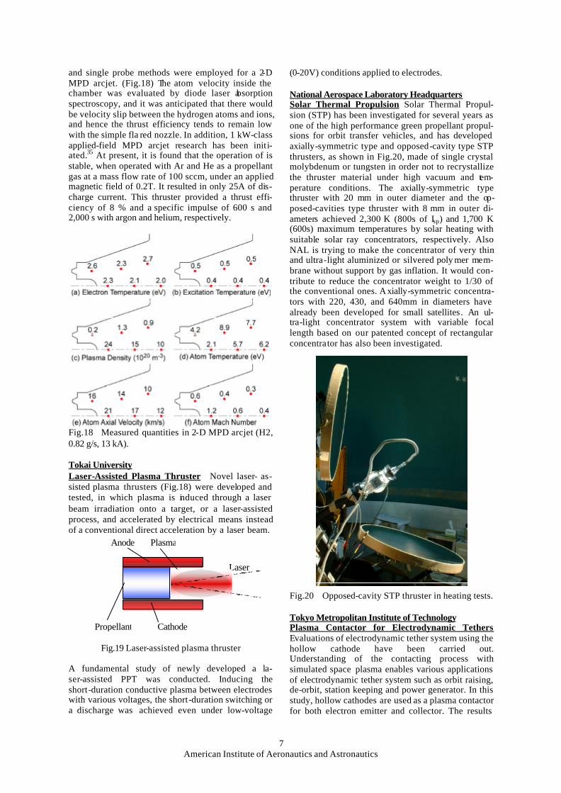
(0-20V) conditions applied to electrodes. National Aerospace Laboratory Headquarters Solar Thermal Propulsion Solar Thermal Propul-sion (STP) has been investigated for several years as one of the high performance green propellant propul-sions for orbit transfer vehicles, and has developed axially-symmetric type and opposed-cavity type STP thrusters, as shown in Fig.20, made of single crystal molybdenum or tungsten in order not to recrystallize the thruster material under high vacuum and tem-perature conditions. The axially-symmetric type thruster with 20 mm in outer diameter and the op-posed-cavities type thruster with 8 mm in outer di-ameters achieved 2,300 K (800s of Isp) and 1,700 K (600s) maximum temperatures by solar heating with suitable solar ray concentrators, respectively. Also NAL is trying to make the concentrator of very thin and ultra-light aluminized or silvered poly mer mem-brane without support by gas inflation. It would con-tribute to reduce the concentrator weight to 1/30 of the conventional ones. Axially-symmetric concentra-tors with 220, 430, and 640mm in diameters have already been developed for small satellites. An ul-tra-light concentrator system with variable focal length based on our patented concept of rectangular concentrator has also been investigated.
Fig.20 Opposed-cavity STP thruster in heating tests. Tokyo Metropolitan Institute of Technology Plasma Contactor for Electrodynamic Tethers Evaluations of electrodynamic tether system using the hollow cathode have been carried out. Understanding of the contacting process with simulated space plasma enables various applications of electrodynamic tether system such as orbit raising, de-orbit, station keeping and power generator. In this study, hollow cathodes are used as a plasma contactor for both electron emitter and collector. The results

American Institute of Aeronautics and Astronautics
8
show the simultaneous operation of the plasma contactors in the simulated space plasma environment. The closed current loop formation via ambient plasma between the emitter and the collector were confirmed, and the plasma cloud around the collector was observed.36 Shizuoka University EP Exhaust Interactions in Upper Atmosphere The ions exhausted from electric thrusters have very high energies compared with the ions in the plasmasphere. If we operate electric thrusters near the earth fre-quently in the future space developments, there is a possibility that the exhausted ions from electric thrusters impacts on the environment in the plasmas-phere. Analytical results37 showed that the exhausted ions from ion thrusters were trapped by the geomag-netic field because the quasi-neutrality of exhausted beam was broken at a few tens km from the exit of thruster; the energy of ions transferred to the ambient particles through collisions, and then the components of the plasmasphere was changed by the heating of particles in the plasmasphere. The detail analysis of the exhausted ion motions and the mechanism of the heating of particles in the plasmasphere is undergoing at present. In addition, the possibility of the applica-tion of exhausted ions to the analysis of the density of upper atmosphere by using the reciprocal reactions between exhausted ions and ambient particles is also studied. Electrodynamic Tether The performances of the electrodynamic tether orbit transfer system and the de-orbit system are analytically studied with the tether dynamics and the modeling of the contactors. The initial analysis 38 showed that the electrodynamic tether could reduce the system mass compared with the conventional ion thruster for the orbit transfer until the altitudes of 6,000-8,000 km. The analysis 39
also showed that the electrodynamic tether could be applied to the de-orbit of debris on the elliptical orbit, but the unstable motion would occur in some situa-tions on the elliptical orbit. Nagoya University Hall Thruster Experimental and numerical studies for controlling a low-frequency discharge oscillation in a Hall thruster are being conducted. In our previous works, a possibility of amplitude control by decreas-ing the neutral density incoming to the ionization zone was predicted40. In the experimental work, heating the propellant decreased the neutral density. As a result, the amplitude of the oscillation decreased as the propellant temperature increased. However, the propellant preheating causes a complicated system. Therefore, in the present study, the control of the os-cillation is studied from the viewpoint of design of inlet part using NUHT-II.41 Figure 21 shows that the dependencies of amplitude and frequency on the di-ameter of anode orifice. Both the amplitude and the frequency decrease for a smaller orifice.
Fig.21 Dependencies of amplitude and frequency on diameter of anode orifice Osaka University Arcjet Thrusters The laboratory-model radiation- cooled arcjet thruster RAT-VII, as shown in Fig.22, was operated in a power range of 400-800W with a mixture of hydrogen and nitrogen simulating hydra-zine at a wide mass flow rate range of 20-50mg/s. With large mass flow rates above 35mg/s, thrust and thrust efficiency were above 110mN and 34%, re-spectively, although the specific impulses were below 390s. Unsteady thermal analyses of the RAT-VII body were conducted using empirical data. As a result, at the power of 500W, 60min was spent to reach a thermal steady-state condition. Then the body is 70%-downsized and the time to reach the thermal steady state was decreased.
Diagnostics was carried out about a 10 kW-class DC arcjet42,43.NH3 and N2+3H2 plasmas in the expan-sion nozzle and in the downstream plume were in thermodynamical nonequilibrium although those in the constrictor throat were nearly in equilibrium. As a result, H-atom excitation temperature and N2 rota-tional excitation temperature decreased from 11,000K at the throat to 4,000K and to 2,000K, respectively, although the NH rotational temperature did not show an axial decrease even in the nozzle.
Fig.22 Radiation-cooled arcjet thruster RAT-VII
MPD Arcjet Thrusters The quasi-steady MPD thruster MY-III was operated to study the exhaust plume characteristics44 along with flowfield calcula-tions. The plasma flow was divided into inner and

American Institute of Aeronautics and Astronautics
9
outer flows with the nozzle extrapolation line. In the inner flow, a large amount of thermal energy was smoothly converted downstream into axial kinetic energy. The calculated properties qualitatively agreed with the measured ones. Because 90 % of ion flux existed within a radius nearly along the nozzle ex-trapolation line, nozzle angle may influence con-tamination of spacecraft.
A magnetic field was applied to a repetitively operated quasi-steady MPD arcjet by using a pulse coil.45 The magnetic field strength is up to 0.45T near the cathode tip. It was operated repetitively with a discharge duration time of 1.5ms and a firing fre-quency of 0.5Hz at a tank pressure below 1Pa. The thrust increased in 50-70% by applying fields with H2 and N2 at low discharge currents of 3-10 kA. Low Power Hall Thruster Basic experiments are being carried out using the THT-IV low-power Hall thruster, to examine the influences of magnetic field shape and strength, and acceleration channel length. (Fig.23) The thruster was stably operated with the highest performance under an optimum acceleration channel length of 20mm and an optimum magnetic field with a maximum strength of about 150G near the channel exit and with some shape considering ion acceleration directions. A new Hall thruster was de-signed with the data, enabling a long stable operation. The thrust and the specific impulse ranged from 15 to 70mN and from 1100 to 2300sec, respectively, in a power range of 300-1300W. The thrust efficiency reached 55%. Thermally safe conditions were achieved with all input powers.
The flowfields were calculated using a simple one-dimensional model.12,46 The influences of mag-netic field strength and acceleration channel length were mainly examined. Because the measured per-formance characteristics did not agree well with the calculated ones, we tried to include unclear anoma-lous electron diffusions by changing a Bohm diffu-sion coefficient depending on field strength. As a result, the calculated thrust characteristic agreed well with the measured one.
Fig.23 Operation of the THT-IV Hall thruster.
Cylindrical Hall Thruster Preliminary experiments were carried out using the cylindrical Hall thruster TCHT-I, as shown in Fig.24, for design of
high-performance very-low-power thrusters for small satellites46. Thrust efficiency increased with mag-netic field strength and reached a maximum of about 22 %. The discharge current oscillation in the TCHT-I thruster was much smaller than those for coaxial Hall thrusters. Its thrust and specific impulse are 18mN and 1,800s, respectively. The thrust efficiency was kept about 21 % regardless of discharge voltage. At present, a half-size thruster of TCHT-I is under de-sign.
Fig.24 TCHT-I cylindrical Hall thruster.
PPT Research and development of pulsed plasma thrusters for micro satellites were started. The PPT, as shown in Fig.25, has a coaxial configuration with a long Teflon tube as the propellant aiming at en-hancement of electrothermal thrust. Thrusts of several ten µN are being measured with a pendulum method.
AnodeCathode
IgnitorSpring Propellant Fig.25 T he coaxial Pulsed plasma thruster.
Spacecraft and Plasma Interactions Equivalent electrical circuits between a spacecraft and the space plasma around it were constructed48. In the space plasma simulator, the segmented ion collector in se-ries with negatively charged capacitors was exposed to argon plasma flows with changing plasma velocity under a constant plasma number density. In cases that a negatively-charged insulating surface disappears from a plasma source, in the shade on view from a plasma source, i.e., in wake condition, particularly with a high plasma velocity, electrical breakdown is suspected to occur by a large difference in mitigation time between the absolute charging of the spacecraft conductive main body and the local charging of the insulating surface. Kyushu University Ion Thruster Plume The backflow of the plume exhausted from the ion engine of the MUSES-C spacecraft is being numerically analyzed by means of the DSMC-PIC method at the department of Aero-

American Institute of Aeronautics and Astronautics
10
nautics and Astronautics. It is the objective to reveal sensitivities of electron temperature, beam expansion angle and cross section for charge exchange reaction to the behavior of CEX ions in the backflow region. Vaporizing Liquid Microthruster Vaporizing liq-uid microthrusters are built and tested using MEMS-based electrothermal technique, whose chan-nel height is of the order of ten micrometers. The starting-up stage of vaporization is investigated con-sidering the effect of wettability. Micro Microwave -Discharge Ion Thruster A satel-lite operated on small and low power can be devel-oped because high integration of semiconductor can miniaturize parts of the satellite. Therefore, at the department of Advanced Energy Engineering Science, a research on a micro ion engine for a small satellite is being made. This has a small microwave discharge plasma source. The objective of this study is to fabri-cate a small plasma source and to evaluate its per-formance as electron and ion sources. Presently, the plasma parameters are being measured, and the elec-tron current is also being extracted from the plasma source. Kyushu Institute of Technology Double-Discharge Pulsed Plasma Thruster In order to improve the propellant vaporization issue and thruster performance of pulsed plasma thrusters, a“Double Discharge Method”was proposed and tested experimentally. In this method, it is expected that part of late-time vaporization gas in the primary discharge be accelerated by the secondary discharge. To perform this double discharge operation, Kyushu Institute of Technology has designed and fabricated original circuitry that consists of two independent capacitors and silicon controlled rectifiers (SCRs.) In the igniter power supply, two successive ignition pulses with set intervals can be made, and two suc-cessive (but independent of each other) discharges can be produced between electrodes. The delay time between the primary and secondary discharge can be adjusted by changing the interval of the igniter firings. Spacecraft Environmental Interactions Interac-tion between ion thruster plume and high voltage solar array onboard a large GEO telecommunication satellite is studied via experiment and computer simulation. A three-dimensional particle simulation code has been developed to calculate the density of plasma near the solar array that is made of charge exchange ions and neutralizer electrons, as shown in Fig.26. The near-spacecraft plasma environment is produced inside a vacuum chamber via a Xenon plasma source. The issues of current leakage and arc-ing are studied via experiment biasing a solar array coupon inside the chamber. As an application of ECR ion thruster, an oxygen plasma source is developed jointly with ISAS. The oxygen plasma source will be used to simulate the LEO plasma environment in a vacuum chamber. The combined effects of electri-cal, chemical, and physical interaction between oxy-gen ions and spacecraft surface material will be stud-ied.
Fig.26 Charge exchange ion density near a GEO sat-ellite. Density of 5x10¹⁰m-3 is marked in yellow.
Mitsubishi Heavy Industries, Ltd. PPT System MHI started research and develop-ment of a PPT system for a micro satellite in 2001. The final target efficiency is η=10 % at 10J for small satellite’s altitude control and 15 % at 30 J. 2) for its orbit transfer. In the experimental approach, MHI can obtain the fundamental data of thruster performance on design parameters as electrode configurations, propellant configurations, and igniter positions. Fig-ure 26 is the picture of firing MHI PPT.
Fig. 27 MHI PPT
Acknowledgements The author gratefully acknowledges the con-tributions of the following members: NASDA, ISAS, NAL, Tokyo Metropolitan Institute of Technology, Hokkaido Institute of Technology, Tohoku Univ., To-kai Univ., Shizuoka Univ., Nagoya Univ., Osaka Univ., Kyushu Univ., Kyushu Institute of Technology, NEC/Toshiba Space Systems, Mitsubishi Heavy In-dustries, Ishikawajima -Harima Heavy Industries, Advanced Technology Institute, and Astro Research Corporation.
References 1 Toki, K., et al.,“ Design and Tests of Microwave Ion
Engine System for MUSES-C Mission,” ISTS-2002-b-1, 2002.
2 Toki, et al., “ Flight Readiness of the Microwave Ion Engine System for MUSES-C Mission,”.IEPC 03-098, 2003.
3 Takegahara, H. and Igarashi, M., et al.,“ Preliminary

American Institute of Aeronautics and Astronautics
11
Experiments on Pulsed Plasma Thruster for Small Satel-lite,” ISTS-2000-b-18, 2000.
4 Burton, R.L. and Turchi, P.J.,” Pulsed Plasma Thruster,” Journal of Propulsion and Power , Vol.14, No.5, 1998, pp.716-735.
5 Takegahara, H. and Sato, K., et al.,“ Evaluation of Pulsed Plasma Thruster System for μ -Lab Sat II,” IEPC-01-153, 2001.
6 Kumagai, N. and Takegahara, H., et al.,“ Plume Diag-nostics in Pulsed Plasma Thruster,” AIAA 2002-4124, 2002.
7 Tamura, K. and Takegahara, H., et al.,“ Evaluation of Propellant Properties for Pulsed Plasma Thruster,” AIAA 2002-4272, 2002.
8 Kumagai, N. and Takegahara, H., et al.,“ Research and Development Status of Low Power Pulsed Plasma Thruster System for Micro-Lab Sat II,”IEPC 03-202, 2003.
9 Kawahara, K., Takegahara, H., et al.,“ Study on Plume Characteristics of Pulsed Plasma Thruster,” IEPC 03-160, 2003.
10 Tahara, H., et al.,” Hall Thruster Research at Osaka University,” AIAA.99-2570, 1999.
11 Tahara, H., et al.,” Operating Characteristics of Low Power Hall Thrusters,”.ISTS-2000-b-36p, 2000.
12 Tahara, H., et al.,” Thrust Performance and Plasma Characteristics of Low Power Hall Thrusters,” IEPC-01-042, 2001.
13 Kitano, T., et al.,,” Research and Development of Low Power Hall Thrusters,” ISTS-2002-b-18, 2002.
14 Tahara, H., et al.,” Optimization on Magnetic Field and Acceleration Channel for Low Power Hall Thrusters,” IEPC 03-015, 2003.
15 Kitamura, S., et al.,“ Research and Development Status of 150-mN Xenon Ion Thrusters,” IAF Paper 00-S.4.06, 2000.
16 Kitamura, S., et al., “ Results of a 35-cm Xenon Ion Thruster Endurance Test,” IEPC-01-083, 2001.
17 Okawa, Y., Hayakawa, et al.,“ Ion Thruster Thrust Vectoring by Grid Translation,” IEPC 03-083, 2003.
18 Nishiyama, K., et al.,“ 30mN-class Microwave Dis-charge Ion Thruster,” ISTS-2002-b-03, 2002.
19 Nishiyama, K., et al.,“ 30mN class Microwave Dis-charge Ion Thruster,” IEPC 03-062, 2003.
20 Funaki, I., et al.,“ 20mN-class Microwave Discharge Ion Thruster,” IEPC-01-103, 2001.
21 Shimizu, Y., et al.,“ Basic Property Measurement of Carbon-Carbon Composite Material for Ion Engine Grid,” ISTS-2002-b-06, 2002.
22 Shimizu, Y., et al.,” Evaluation of New Car-bon-Carbon Composites Material for a 20cm Ion Engine,” IEPC 03-097, 2003.
23 Satori, S., et al.,“ New Electrostatic Thruster for Small Satellite Application,” AIAA 2000-3, 2000.
24 Satori, S., et al.,” Design Status of Engineering Model of Microwave Discharge Electrostatic Thruster,” 3rd International Conference on Spacecraft Propulsion, Cannes, France, 2000.
25 Satori, S., et al.,“ Development of Microwave En-gine,” IEPC 2001.
26 Inutake, M., et al.,” Supersonic Plasma Flow in a Magnetic Nozzle,” IEPC 99-175, 1999.
27 Yamamoto, N., et al.,” Condition of Stable Operation in a Hall Thruster,” IEPC 03-086, 2003.
28 Kumakura, K., Komurasaki, K. et al.,” Plasma Mod-eling of a Hollow Anode for an Anode Layer Type Hall Thruster,” IEPC 03-116, 2003.
29 Koizumi, H., et al.,” Liquid Propellant Pulsed Plasma Thruster,” IEPC 03-083, 2003.
30 Koizumi, H., et al.,” Microthruster Experiment Using a Diode Laser,” AIAA 2003-4568, 2003.
31 Kuninaka, H.,“ Deep Space Exploration by Electric Propelled Delta-V Earth Gravity Assist (EP∆VEGA MUSES-C Toward Jupiter,” AIAA 2002-3970, 2002.
32 Molina-Morales P. et al.,“ Microwave Hall thruster Development,” IEPC 03-057, 2003.
33 Kameoka, M., et al.,“ Single Impulse Measurement of a Coaxial Pulsed Plasma Thruster,” IEPC 03-093, 2003.
34 Kinefuchi, K., et al.,“ Nozzle Shape Effects on Veloc-ity Distribution in an MPD Arcjet,” IEPC 03-056, 2003.
35 Nakano, T.,“ A Feasibility Study of a Low-Power Ap-plied-Field MPD Arcjet,” IEPC 03-092, 2003.
36 Kozakai, M. and Takegahara, H.,” Evaluation of Plasma Contactor Ground Experiments for Electrodynamic Tether,” IEPC-01-242, 2001.
37 Yamagiwa, Y., et al.,“ Analytical Study on the Be-havior of Ion Thruster Exhausted Plasma in Near Earth Orbit and Its Influence on Earth’s Environment,” J. of Ja-pan Soc. for Aero. and Space Sci., Vol.49, No.567, 2001, pp.15-22 (in Japanese).
38 Yamagiwa, Y., et al.,“ Preliminary Analysis on the Quick Disposal on Used H-II Upper Stage by Electrody-namic Tether,” Trans. of the Japan Soc. for Aero. and Space Sci., Vol.44, No.144, 2001, pp.106-110.
39 Yamagiwa, Y., et al.,” Analytical Study of the Per-formance of Electrodynamic Tether Orbit Transfer System with Consideration of Lifetime by Impact of Space Debris,” Trans. of the Japan Soc. for Aero. and Space Sci., Vol.44, No.146, 2002, pp.183-189.
40 Furukawa, T., Miyasaka, T. et al.,” Control of Low-Frequency Oscillation in a Hall Thruster,” Trans. of the Japan Soc. for Aero. and Space Sci., Vol.44, 2001, pp.164-170.
41 Miyasaka, T et al.,” Influence of Propellant-Inlet Condition on Hall Thruster Performance,” IEPC 03-091, 2003.
42 Mitsufuji, S., Tahara, H., et al.,” Direct-Current Arcjet Plasma Feature Using Ammonia and Mixture of Nitrogen and Hydrogen,” IEPC-99-039, 1999, pp.270-277.
43 Tahara, H., et al.,” Plasma Characteristics of a 10-kW-Class DC Arcjet,” ISTS-2002-b-35p, 2002.
44 Tahara, H., et al.,” Exhaust Plume Characteristics of Quasi-Steady MPD Thrusters,” IEPC-01-133, 2001.
45 Kagaya, Y., Tahara, H., et al .,” Effect of Applied Magnetic Nozzle in a Quasi-Steady MPD Thruster,” IEPC 03-31, 2003.
46 Tahara, H., et al.,,” Simple One-Dimensional Calcu-lation of Hall Thruster Flowfields, IEPC 03-016, 2003.
47 Shirasaki, A., Tahara, H., et al.,” Operational Charac-teristics of Cylindrical Hall Thrusters, IEPC 03-051, 2003.
48 Tahara, H., et al.,” Mitigation Process of Spacecraft Negative Charging by Plasma Flow,” IEPC-01-258, 2001.