Embed Size (px)
Citation preview

AN OPTICAL WAVELENGTH MULTI/DEMULTIPLEXING
(DWDM/CWDM) BASED ON ARRAY WAVEGUIDE GRATING (AWG)
TECHNIQUE
ISMAHAYATI BINTI ADAM
A project report submitted in partial fulfillment of the
requirements for the award of the degree of
Master of Engineering (Electronic-Telecommunication)
Faculty of Electrical Engineering
Universiti Teknologi Malaysia
MAY 2008

iii
Special dedicated to:
My beloved family, brothers and sisters
For their never ending support and blessing
To my friends
That is always on my ups and down
Thanks for all

iv
ACKNOWLEDGEMENT
Alhamdulillah, praises to Allah S.W.T. the Most Gracious, The Most Merciful, whose blessing and guidance have helped me through my thesis smoothly. Peace is upon our Prophet Muhammad S.A.W. who has given light to mankind.
I would like to take this opportunity to express my heartfelt gratitude to my project supervisor, Dr. Mohd Haniff Ibrahim for his warming encouragement and effective guidance, thanks for having faith in me. My sincere appreciation also extends to Photonic Laboratory of UKM, Prof Dr. Sahbudin Shaari and Abang Annuar Ehsan who willingly let me use their facilities and help me throughout this project.
My deepest thanks and gratitude to my dearest family, brothers and sisters for their never ending love and support. I thank them for always believing in me, with their priceless support, and for driving me to bring out the best in me. Without them, this work would not have been possible.
Finally, thanks to all my friends, individual persons who have either direct or indirectly gave their helps and valuable support in this project. Thanks for being a part of my thesis project.
My Allah bless all of you
Thank you

v
ABSTRACT
Wavelength splitting (demultiplexing) and combining (multiplexing) are
important functions in many optical applications. Wavelength Division
Multiplexing (WDM) enable optical multiplexing and demultiplexing in which
the signals having different light wavelengths can be separated or combined to
transmit in single fibre optic. There are two alternatives in WDM which are,
Dense WDM (DWDM) for high capacity and long haul transmission, while
Coarse WDM (CDWM) mean for shorter transmission and metro network.
CWDM allows the wavelengths to be spaced farther apart, which allows for
economical solutions in sparse applications (around 20nm) as compared to
DWDM which utilizes very closely spaced wavelengths (around 0.8nm).
Arrayed waveguide grating (AWG) multiplexer is a key element for wavelength
division multiplexing (WDM) systems in optical telecommunication. The
advantages of AWG are the flexibility of selecting its channel number and
channel spacing. In this project, conventional AWGs with 4x4 channels
structure based on polymer with channel spacing for DWDM/CWDM and core
size 3 um x 4 um have been designed which centre wavelength 1550nm. The
designs have been carried out by using WDM_phasar design tool from
Optiwave Corporation. The performance and optimization of the designed
AWGs have been analyzed based on parameters studied.

vi
ABSTRAK
Pemisahan (penyahmultipleksan) dan pencantuman (pemultipleksan)
panjang gelombang merupakan fungsi penting dalam aplikasi optik.
Pembahagian pemultipleksan panjang gelombang (WDM) membolehkan
pemultipleksan dan penyahmultipleksan optik dengan setiap isyarat-isyarat
yang mempunyai gelombang cahaya yang berlainan boleh dipisahkan ataupun
dicantumkan bagi menghantar dalam satu gentian optik. Terdapat dua alternatif
dalam WDM iaitu WDM padat (DWDM) untuk kapasiti yang tinggi dan
penghantaran jarak jauh, manakala WDM kasar (CWDM) untuk penghantaran
yang lebih dekat dan rangkaian metro. CWDM membenarkan pemisahan
panjang gelombang yang besar yang mana memberikan penyelesaian yang
ekonomi bagi aplikasi yang rendah (sekitar 20 nm) jika dibandingkan dengan
DWDM yang menggunakan jarak panjang gelombang yang sangat dekat/padat
(sekitar 0.8 nm). Dalam telekomunikasi optik, pemultipleksan parutan pandu
gelombang tersusun (AWG) merupakan elemen utama bagi sistem pembahagian
pemultipleksan panjang gelombang (WDM). Kelebihan AWG adalah
kefleksibelannya dalam memilih bilangan saluran dan pisahan saluran. Dalam
projek ini, 4x4 saluran AWG konvensional yang binaannya berasaskan polimer
dengan pisahan saluran untuk DWDM/CWDM serta saiz teras 3um x 4 um telah
direkabentuk dengan panjang gelombang tengah 1550 nm. Rekabentuk telah
dijalankan dengan menggunakan perisian WDM_Phasar daripada Optiwave
Corporation. Prestasi dan pembaikan AWG yang direkabentuk dianalisis
berdasarkan parameter-parameter yang dikaji.

vii
TABLE OF CONTENTS
CHAPTER TITLE PAGE
DECLARATION ii
DEDICATION iii
ACKNOWLEDGEMENT iv
ABSTRACT v
ABSTRAK vi
TABLE OF CONTENTS vii
LIST OF TABLES x
LIST OF FIGURES xi
LIST OF ABBREVIATIONS xiii
LIST OF SYMBOLS xv
LIST OF APPENDICES xvii
1 INTRODUCTION 1
1.1 Background 1
1.2 Problem Statement 4
1.3 Objectives 5
1.4 Scope of Study 5
1.5 Research Methodology 6
1.6 Thesis Outline 7
2 LITERATURE REVIEW 8
2.1 Chapter Outline 8
2.2 Wavelength Division Multiplexing 8
2.3 Dense Wavelength Division Multiplexing 10

viii
2.4 Coarse Wavelength Division Multiplexing 11
2.5 Array Waveguide Grating 13
2.5.1 Basic Operation 14
2.5.2 Focusing 15
2.5.3 Dispersion 16
2.5.4 Free Spectral Range 17
2.5.5 Insertion Loss and Non-uniformity 18
2.5.6 Channel Bandwidth 19
2.5.7 Channel Crosstalk 20
2.5.8 Polarisation Dependence 21
2.5.9 AWG Design 22
2.5.9.1 Channel Spacing and Numberof Port 23
2.5.9.2 Receiver Waveguide Spacing 23
2.5.9.3 FPR Length 24
2.5.9.4 Length Increment 25
2.5.9.5 Aperture Width 25
2.5.9.6 Number of Array Waveguide 26
2.6 Polymer Material 26
3 METHODOLOGY 29
3.1 Chapter Outline 29
3.2 AWG Design Procedures 30
3.2.1 Waveguide Structure Modelling 32
3.2.2 Waveguide Curvature Loss 34
3.2.3 Simulation Parameter 35
4 RESULT AND DISCUSSION 39
4.1 Chapter Outline 39
4.2 Result 39
4.2.1 Simulation Result for 50GHz spacing 40
4.2.2 Simulation Result for 100GHz spacing 43
4.2.3 Simulation Result for 500GHz spacing 46
4.2.4 Simulation Result for 1000GHz spacing 49
4.2.5 Simulation Result for 1600GHz spacing 51

ix
4.3 Discussion 53
4.3.1 Relationship between Design Parameter 53
4.3.2 Analyzed Theory and WDM 59
5 CONCLUSION AND RECOMMENDATION 64
5.1 Conclusion 64
5.2 Recommendation 65
REFERENCES 67
Appendices A-G 71-77

x
LIST OF TABLES
TABLE NO. TITLE PAGE
4.1 Design parameters for AWG with 50GHz channels
spacing 41
4.2 Output Statistic for 4 channel AWG (50GHz) 43
4.3 Design parameters for AWG with 100GHz channels
spacing 43
4.4 Output Statistic for 4 channel AWG (100GHz) 45
4.5 Design parameters for AWG with 500GHz channels
spacing 46
4.6 Output Statistic for 4 channel AWG (500GHz) 48
4.7 Design parameters for AWG with 1000GHz channels
Spacing 48
4.8 Output Statistic for 4 channel AWG (1000GHz) 50
4.9 Design parameters for AWG with 1600GHz channels
Spacing 51
4.10 Output Statistic for 4 channel AWG (1600GHz) 53

xi
LIST OF FIGURES
FIGURE NO. TITLE PAGE
1 Project flow chart 6
2.1 Wavelength Division Multiplexing 9
2.2 Metro CWDM Wavelength Grid as specified by
ITU-TG.694.2 12
2.3 (a) The structure of AWG demultiplexer 14
2.3 (b) Output free propagation region (FPR) 14
2.4 Crosstalk resulting from the coupling between two
adjacent receiver channels 24
2.5 Transmitted power (solid line) and crosstalk as a
function of the relative array aperture θa / θo 25
3.1 Flowchart in designing AWG using WDM_Phasar 31
3.2 Effective index calculator dialog box 32
3.3 Various geometries of optical channel waveguide;
(a) strip loaded, (b) ridge, (c) embedded strip, (d) buried
and (e) rib 34
3.4 4x4 channel AWG 34
3.5 Statistic monitor dialog box 35
3.6 Scan parameter dialog box for simulation in
WDM_Phasar 36
3.7 Calculation dialog 37
3.8 Simulation result dialog for 4x4 channels AWG 38
4.1 4 Channels AWG in C + L band 40
4.2 4 channel AWG with 50GHz channel spacing 41
xii
4.3 Output power versus wavelength for 4 channels AWG
(50GHz) 42
4.4 4 channel AWG with 100GHz channel spacing 44
4.5 Output power versus wavelength for 4 channels AWG
(100GHz) 45
4.6 4 channel AWG with 500GHz channel spacing 46
4.7 Output power versus wavelength for 4 channels AWG
(500GHz) 47
4.8 4 channel AWG with 1000GHz channel spacing 49
4.9 Output power versus wavelength for 4 channels AWG
(1000GHz) 50
4.10 4 channel AWG with 1600GHz channel spacing 51
4.11 Output power versus wavelength for 4 channels AWG
(1600GHz) 52
4.12 Channel spacing versus path length different 54
4.13 Channel spacing versus diffraction order 55
4.14 Channel spacing versus FSR 56
4.15 Channel spacing versus bandwidth (BW) 57
4.16 modified diffraction order versus FSR 58

xiii
LIST OF ABBREVIATIONS
AWG - Array Waveguide Grating
BCB - Benzocyclobutene
BPM - Beam Propagation Method
C-band - Conventional band
CDM - Code Division Multiplexing
CWDM - Coarse Wavelength Division Multiplexing
DFB - Distributed Feedback
d-PFMA - deuterated fluoro-methacrylate
DWDM - Dense Wavelength Division Multiplexing
EDFA - Erbium Doped Fiber Amplifier
FBG - Fiber Bragg Grating
FPR - Free Propagation Region
FSR - Free Spectral Range
GaAs - Gallium arsenide
Gbps - Gigabits per second
GHz - Gigahertz
GUI - graphical user interface
IA - Input array
ITU - International Telecommunication Union
LAN - Local area network
L-band - Long band
MMI - Multimode interference
OA - Output array
OADM - Optical Add Drop Multiplexer
ORMOCER - Organically modified ceramics

xiv
PA - Phased array
PAWG - Phased array waveguide grating
PLC - Planar Lightwave circuit
PHASAR - Phased array
PDL - Polarization dependence loss
Si - Silicon/silica?
SMF - Single mode fiber
TDM - Time Division Multiplexing
TE - Transverse electric
TFF - Thin film filter
TM - Transverse magnetic
WDM - Wavelength Division Multiplexing
WGR - Wavelength grating router

xv
LIST OF SYMBOLS
LΔ - path length different
λΔ - channel spacing in wavelength
fΔ - channel spacing in frequency
λ - wavelength
m - diffraction order
cf - centre frequency
cλ - centre wavelength
Nch - number of channel
dTdn - Thermo-optic coefficient
)( cfT - transmission in dB at the channel maximum
U(s) - normalized modal field
Neff - effective index of waveguide mode
da - spacing between array waveguide
D - dispersion
dr - receiver spacing
R - free propagation region length
β - propagation constant
ΔΦ - phase different
we - effective mode width
Δfpol - polarization dispersion
Ng - group refractive index
maxθ - maximum dispersion angle
aθ - aperture width

xvi
Na - number of waveguide

xvii
LIST OF APPENDICES
APPENDIX TITLE PAGE
A Curvature loss for AWG (50 GHz) 71
B Curvature loss for AWG (100 GHz) 72
C Curvature loss for AWG (500 GHz) 73
D Curvature loss for AWG (1000 GHz) 74
E Curvature loss for AWG (1600 GHz) 75
F Simulation Result for 200GHZ 76
G Simulation Result for 1200GHZ 77

2
Wavelength splitting (demultiplexing) and combining (multiplexing) are
important functions in optical applications. Wavelength Division Multiplexing
(WDM) technology enable optical multiplexing and demultiplexing with the
individual signals have different light wavelength can be separated or combined to
transmit in single fibre optic.
There are two alternatives for WDM metro networks: dense WDM
(DWDM) and coarse WDM (CWDM). In high capacity environments, DWDM is
used. In DWDM, the channel separation can be as small as 0.8 or 0.4 nm, for up to
80 optical channels at line rates up to 10 Gbps. DWDM technologies is very
expensive, so its application to access networks is difficult. Instead, CWDM is
merging as a robust and economical solution. The advantage of CWDM technology
lies in its low-cost optical components. CWDM offers solutions for 850, 1,300, and
1,500 nm applications at 10 and 40 Gbps on up to 15 optical channels spaced 20 nm
apart. Both CWDM and DWDM technology have their place in current and
emerging metro-network infrastructure.
Many technologies are used in optical multiplexing, such as thin film filters
(TFFs), array waveguide gratings (AWGs), acousto optical tunable filters, mach-
Zehnder interferometers and Fiber bragg gratings (FBGs) in order to overcome
problems such as channel spacing, bandwidth, crosstalk and insertion loss.
However, arrayed waveguide grating (AWG) multiplexer based on planar lightwave
circuit (PLC) is the most likely used in wavelength division multiplexing (WDM)
systems in optical telecommunication and it’s been focused to study in this project.
The key advantage of the AWG is that its cost is not dependent on
wavelength count as is the dielectric filter solution. Therefore it suits metropolitan
applications that require the cost-effective of large wavelength counts. Not only the
approach is easily scalable, but the use of fiber-alignment methods depend on the
whole wafer photoligraphy, rather than channel-by-channel alignment, further
enhances the cost-effectiveness of this approach at higher channel counts. Other

3
advantage of the AWG is the flexibility of selecting its channel number and channel
spacing, as a result, various kinds of AWG’s can be fabricated in a similar manner
(Kien and Shaari 2000).
AWG multiplexers have already been developed using silica,
semiconductors such as Si, GaAs, etc and polymers as the waveguide materials. Of
the materials, polymers offer excellent potential for the realization of low-cost
WDM components because they can be fabricated easily at low temperature on
various kinds of substrates. (Kien and Shaari 2000)
AWG multiplexers based on polymeric waveguides have been gaining
increasing attention because polymer devices are believed to be produce-able at
lower cost than their conventional silica-based counterparts. Moreover, as polymer
materials have a thermo-optic coefficient (dn/dT) roughly ten times larger than
silica, polymeric AWG devices can be thermally tuned over a wider spectral range
and may be integrated with polymer optical switches to form an add-drop
multiplexer with much lower switching power consumption (Kein et al, 2001)
The first polymer AWG demonstrated by Hida et al 1994 applying
deuterated fluoro-methacrylate (d-PFMA) on silicone substrate. However, this
AWG only operated at 1300 nm window with some polarization dependence as
small as 0.03 nm. Watanabe et al (1997) reported 16 channels polymeric AWG
operated at 1550 nm realized using a silicone resin waveguide. This AWG
multiplexer has an insertion loss in the range 9-13dB, a crosstalk less than -20dB,
and a low polarization dependent wavelength shift.
In 1999, Beelen et al demonstrated 8 channels polymeric AWG with high
index contrast of 0.01. By this technique, smaller bend radii can be achieved and it
lead to smaller AWG dimension from 66x11 mm to 16x6 mm. Keil et al (2001)
reported athermal polymer AWG consisting of polymer waveguide fabricated on a

4
polymer substrate. On the other hand, Ahn et al (2004) proposed and fabricated an
all-polymer based cost effective wavelength channel selector by using chip-to-chip
bonding of a 16 channels to polymer switch array between two polymers AWG.
However, the penalties are large insertion loss and low power of 0.1 dB at 10 Gb/s.
Huang Chang Lin et al (2005) designed a low loss, low crosstalk and low
PDL SU-8 polymeric wavelength division multiplexer AWG with temperature
variation in range of 0 – 70oC. In year 2006 a compact wavelength division
multiplexer based on AWG structures have been fabricated for CWDM using low-
loss perfluorocyclobutane-containing polymers by Jiang et al. The device exhibit
high thermal stability and low on chip losses.
1.2 Problem Statement
There is demand for high capacity and cost effective for the long and short
haul application optical transmission. WDM offers a new dimension for solving
capacity and flexibility problems in the telecommunication network. Key
motivation for this study is the importance of optical multiplexing and
demultiplexing component in optical telecommunication network which are crucial
elements in WDM technology, namely the Dense WDM and Coarse WDM. There
are also claims for these technologies and the needs of precise design with low cost
fabrication process. The polymer waveguide technology is chosen because of low
material cost and easy fabrication process. Motivated from the advantages of
polymer material, the development of polymer based AWG is initiated in this
project.

5
1.3 Objective
The main objective of this project is to design and simulate conventional
four channel AWGs structure based on the BenzoCyclobutene (BCB 4024-40)
polymer for DWDM and CWDM application. To employ this objective, thorough
studies and researches are to be conducted in order to get relevant informations and
also to gain the required knowledge.
1.4 Scope of study
This project is intended for the design and simulation of four channels
AWGs structure based on BCB 4024-40 polymer for Wavelength Division
Demultiplexing application.
To make this project successful, several scopes are listed to ensure the
project is conducted within its intended time frame. The first scope for this project
is to understand the concept of DWDM/CWDM and AWG, and also the
characteristics of the BenzoCyclobutene (BCB 4024-40) polymer, which is
currently being used in the Photonics Research Lab. Literature review was done to
find out the related theory.
The second scope of work is to specify the parameters of the design based
on mathematical equation of basic design rules for AWG. Suitable numbers of
waveguide channel have been studied to figure out the best structure to be
implemented in this study. Then, conventional AWGs with 4x4 channels structure
based on polymer with varies spacing between the channels for DWDM and
CWDM environment will be designed at centre wavelength of 1550nm. Modelling

6
and simulation will be carried out by using WDM_Phasar software, from Optiwave
Corporation. With this software, AWG performance such as bandwidth, insertion
loss, output power and crosstalk will be analysed.
1.5 Research Methodology
Figure 1 shows the overall project activities. The project begins with literature
review on fundamental of DWDM/CWDM and AWG characteristics. After the
design parameter is determined, the project is followed by proceeding with the
design. Following this, the designs will be analysed and its performances will be
evaluated.
Design and Analysis
Modeling and Simulation WDM_Phasar Simulation-Modelling the AWG devices.
Result analysis and Evaluation Analysis of Simulation Data : Analysis of the AWG
performance.
Literature review Through literature work and review on the CWDM/DWDM
Network and AWG structure
System Optimiz-ation
Report Writing
Figure 1 Project Flow Chart

7
1.6 Thesis Outline
In this thesis the design and simulation AWGs multiplexer/demultiplexer are
presented. The background, objectives, scopes and research methodology are
discussed in Chapter 1. The literature review of wavelength division multiplexer
(WDM) technology, array waveguide grating (AWG) characteristic and polymer
material are presented in Chapter 2. The design procedure and AWG simulation are
discussed in Chapter 3. The results, analysis and discussion of the simulated results
and comparison of the designed devices are presented in Chapter 4. Finally, the
conclusion and recommendations for future works are given in Chapter 5.

CHAPTER 1
INTRODUCTION
1.1 Background
The increase in end-user bandwidth demand, along with the decrease in
WDM component cost, implies that WDM-based devices are likely to offer
performance enhancements in multiple-access networks. Wavelength division
multiplexing (WDM) is considered as a promising solution to the demand for
tremendous transmission capacity of the optical fiber communications network
required in the near future.
Commercial interest in WDM components and systems is rapidly increasing.
WDM provides a new dimension for solving capacity and flexibility problems in
the telecommunication network. It offers a huge transmission capacity and allows
for novel network architectures that offer much more flexibility than the current
networks. No new fibre upgrade needed for adding new services (new capacities) to
an existing fiber. Key components in WDM systems are the wavelength
multiplexers and demultiplexers.

CHAPTER 2
LITERATURE REVIEW
2.1 Chapter Outline
In this chapter, fundamental of wavelength division multiplexing (WDM)
network and AWG’s structure will be described in detail. First part of the chapter
explained two alternatives of WDM network which are Dense WDM and Coarse
WDM. Then, the chapter continues with the theory of the AWG which is the key
element of WDM network and it is the main focused in this thesis. Chapter two end
with literature review on BCB-4024 polymer material.
2.2 Wavelength Division Multiplexing
One of important enabling technologies for optical networking is
wavelength division multiplexing (WDM). The basic concept of WDM is
illustrated in Figure 2.1. WDM technology uses wavelengths to transmit data
parallel-by-bit or serial-by-character, which increases the capacity of the fibre by

9
assigning incoming optical signal to specific frequencies (wavelengths) within
designated frequency band and then multiplexing the resulting signals out into one
fibre. It provides a new dimension of solving the increase demand in high capacity
transmission, which poses a serious limitation for the existing carrier technologies
by offers a huge transmission capacity and allows for novel network architectures
that offer much more flexibility than the current networks.
Figure 2.1 Wavelength Division Multiplexing
In WDM, different end users operate only at electronic speed but huge opto-
electronic bandwidth mismatch is overcome by multiplex many WDM channels
from different users onto a fibre. By contrast, time division multiplexer (TDM)
and code division multiplexer (CDM) required for end users to operate at rate
higher than electronic speed which made them less interest to be employed in
network compare to WDM. Furthermore, it is cost effective to employed WDM
technologies into network as there is no new fibre upgrade need for adding new
services (new capacities) to an existing fibre.
Research and development on optical wavelength division multiplexing
(WDM) networks have matured considerably. Its have been applied for local,
access, metro and long haul network architecture.

10
2.3 Dense Wavelength Division Multiplexing
Dense Wavelength Division Multiplexing (DWDM) technology was
developed for large number of channels of lights with different wavelengths that need
to be transmit within one single fibred. This increases the bandwidth capacity of a
single fiber by tens or even hundreds of times. DWDM has been deployed for long-
haul transmissions and will surely change the landscape of fiber-to-the-home network
architecture and protocols. The DWDM technology can be applied to different areas
in communication networks, which includes the backbone networks, the Local Area
Networks (LANs) and also the residential access (Song and Wua).
DWDM has been popular with carriers for some time. It was originally used
to mitigate bandwidth issues in backbone long-haul voice applications, but is now
used for a broader spectrum of applications, where high bandwidth is needed.
Extended distances of up to 600km are supported, but require expensive EFDAs
(Erbium Doped-Fiber Amplifiers) to boost power.
DWDM uses expensive narrow-bandwidth (0.8nm) filters and requires
specialized cooling to stabilize laser temperatures. The standard calls for up to 80
channels, but typical DWDM implementations support 16-40 wavelengths or
channels, at speeds from 2.5 Gbps to 10 Gbps per wavelength (Lounsbury, 2007).
DWDM technology is very efficient for long-haul networks. It not only
supports long distances, a multitude of channels and high aggregate bandwidth, but it
offers the sophisticated end-to-end management tools required in carrier networks. A
far larger number of customers can be supported concurrently, spreading the
infrastructure costs over a larger group of users (Lounsbury, 2007).

11
DWDM is a “hot” technology in every sense of the word. The high density of
channels over a narrow frequency range from 1530 - 1620nm (spanning the C- and L-
bands) requires expensive filters and cooling and consumes a lot of power. However,
all this makes for larger engineering and manufacturing efforts bundled in a larger-
than-optimum package. Complexity, cost, colossal equipment footprints combine to
leave room for alternative WDM transmission facilities to emerge.
2.4 Coarse Wavelength Division Multiplexing
Coarse wavelength division multiplexing is a form of wavelength division
multiplexing that has wider spacing between the wavelengths used than Dense WDM.
Also, unlike other forms of WDM, it uses a far broader photonic band spectrum than
other such systems, which often are confined to one or two bands. Up to 18
wavelengths can be sent using some schemes of CWDM. CWDM can be used over
multimode and single-mode fibres although signal distances are generally shorter than
DWDM. The costs of deploying CWDM are significantly lower than DWDM (RBN
Inc., 2002).
CWDM technologies have been in use since the early 1980s, long before the
general acceptance of WDM into the telecom network. Initial deployments involved
multiple wavelengths with 25 nm spacing in the 850 nm window over multimode
fibre local area networks (LANs). Applications included multi-channel video
distribution and bi-directional, latency sensitive telemetry and control information
transmitted over a single optical fibre (ADC whitepaper).

12
Figure 2.2 Metro CWDM Wavelength Grid as specified by ITU-T G.694.2
The ITU has set the standards of 20-nm channel spacing starting from 1270-nm and
ending at 1610 nm, giving up to 18 channels.
Such large channel spacing delivers the following advantages (VPI photonics):
• Temperature control is not required for laser sources, even for outside plant,
giving lower power consumption
• Transmitters are cheaper (typically 1/5 of Dense-WDM)
• Muxes, Demuxes and OADMs are cheaper (1/3 cost of DWDM)
• Each wavelength can carry a broadband service without crosstalk, (analog and
digital services on the same fiber without degradation of the analog service)
Metro CWDM technologies now comprise optical filters and un-cooled lasers
with 20 nm spacing. There are 18 wavelengths currently specified with nominal
wavelengths ranging from 1270 nm to 1610 nm inclusive. Figure 2 shows a mapping
of the ITU-T G.694.2 CWDM wavelength grid. A typical attenuation curve for the

13
installed base of ITU-T G.652 fibre is also shown. The mapping of CWDM
wavelengths onto the fibre attenuation curve has been done for greater clarity and to
highlight the higher loss incurred by some wavelengths.
2.5 Array Waveguide Gratings
In recent years, the arrayed waveguide grating (AWG) has become increasingly
popular as a wavelength multiplexer and demultiplexer for WDM applications. This
popularity is largely due to the fact that AWG device have been proven capable of
precisely de(multiplexing) a high number of optical signals. AWG also known as the
optical phased array (PHASAR), phased array waveguide grating (PAWG) or
waveguide grating router (WGR).
The arrayed waveguide grating was first proposed a solution to the WDM
problem by Smit in 1988 and was further developed in the following years by
Takahashi who reported the first devices operating in the long wavelength window.
Dragone, extended the concept from 1 x N demultiplexers to N x N wavelength
routers which play an important role in multi-wavelength network application. Since
then, researchers have designed many AWGs seeking to improve them by increasing
the number of channels, decreasing the wavelength spacing, increasing transmission,
lowering crosstalk, and reducing the size of the device. These AWGs have many
applications in addition to simple demultiplexing applications, including add/drop
filters, cross-connects, channel equalization, and multi-frequency lasers (Smit, 1996).

14
2.5.1 Basic Operation
Generally AWG device serve as multiplexers, demultiplexers, filters and ad-
drop devices in optical WDM applications. Figure 2.3 (a) shows a schematic layout of
an AWG demultiplexer. The device consists of three main part which are input and
output waveguide, two slab waveguide star couplers (or free propagation region
(FPR)), connected by a dispersive waveguide array with the equal length difference
between adjacent waveguides. The operation principle of the AWG
multiplexer/demultiplexer is described as follows.
Input waveguide
Output waveguide
Input FPR Output FPR
Arrayed waveguide
Figure 2.3 (a) The structure of AWG demultiplexer
Figure 2.3 (b) Output free propagation region (FPR) (Smit, 1996)

15
Light propagating in the input waveguide is diffracted in the slab region and
coupled into the arrayed waveguide by the first FPR. The length of the array
waveguides has been designed such that the optical path length difference (ΔL)
between adjacent array waveguides equals an integer (m) multiple of the central
wavelength (λc) of the demultiplexer. As a consequence, the field distribution at the
input aperture will be reproduced at the output aperture. Therefore, at this centre
wavelength, the light focuses in the centre of the image plane (provided that the input
waveguide is centred in the input plane) (Amersfoort, 1998).
If the input wavelength is detuned from this central wavelength, phase changes
occur in the array branches. Due to the constant path length difference between
adjacent waveguides, this phase change increases linearly from the inner to outer
array waveguides, which causes the wavefront to be tilted at the output aperture.
Consequently, the focal point in the image plane is shifted away from the centre
(Amersfoort, 1998). By placing receiver waveguides at proper positions along the
image plane, spatial separation of the different wavelength channels is obtained.
2.5.2 Focusing
Focusing is obtained by choosing the length difference ΔL between adjacent
array waveguides equal to an integer number of wavelengths, measured inside the
array waveguides (Smit, 1996):
ΔL = m . eff
c
Nλ
(2-1)

16
Where m is the order of the phased array
λc is the central wavelength
Neff is the effective index of the waveguide mode
With this choice the array acts as a lens with image and object planes at a
distance Ra of the array apertures. The input and output apertures of the phased array
are typical examples of Rowland-type mountings. The focal line of such a mounting,
which defines the image plane, follows a circle with radius Ra/2 as shown in Figure
2.3 (b).
2.5.3 Dispersion
By referring to Figure 2.3 (b) it can be seen that the dispersion angle
θ resulting from a phase difference ΔΦ between adjacent waveguides follows as
(Smit, 1996):
⎟⎟⎟
⎠
⎞
⎜⎜⎜
⎝
⎛ −ΔΦ
=a
FPR
d
mβ
π
θ
)2(
arcsin = aFPRd
mβ
π2−ΔΦ (2-2)
Where ΔΦ = β ΔL
Β and βFPR are the propagation constants in the array waveguide
and Free Propagation Reion (FPR)
da is the lateral spacing(on centre lines) of the waveguides in
the array aperture

17
The dispersion D of the array is described as the lateral displacement ds of the
focal spot along the image plane per unit frequency change. From Figure 1(b) it
follows:
chf
drdfdR
dfdsD
Δ===
θ (2-3)
Where dr is the receiver spacing
R is the length free propagation region (FPR)
is the channel spacing in GHz chfΔ
2.5.4 Free Spectral Range
An important property of AWG is the free spectral range (FSR), also known as
demultiplexer periodicity (Amersfoort, 1998). This periodicity is due to the fact that
constructive interference at the output FPR can occur for a number of wavelengths.
The free spectral range (ΔλFSR,) denotes the wavelength and frequency spacing
between the maxima of the interference pattern because of the periodic characteristic
of the AWG transfer function, and can be obtained after ignoring material dispersion
of the core refractive index nc.
mNFSR c /λλλ ≈Δ=Δ (2-4)
Where N is the number of wavelengths
λΔ is the wavelength channel spacing in nm
m is the diffraction order

18
To prevent different orders from overlapping it is significant to make sure that
larger or equal the no of channel multiplied by channel spacing. For a fixed Free
Spectral Range (FSR), the diffraction order can be calculated by using expression:
⎟⎟⎠
⎞⎜⎜⎝
⎛Δ
=Δ
=FSR
c
ch
c roundN
mλλ
λλ
(2-5)
2.5.5 Insertion Loss and Non-uniformity
The primary cause for insertion loss in the AWG is due to inefficient coupling
at the interface between the first FPR and the AWs. Due to reciprocity, identical loss
occurs at the second AW - FPR interface into higher diffraction orders. Coupling
efficiency, and therefore insertion loss is largely determined by the separation of the
AWs at these interfaces, where smaller separations increase the coupling efficiency
(McGreer, 1998). However, at small separations, coupling between the AWs
becomes significant. This effect has to be carefully quantified through the Finite
Difference- Beam Propagation Method (FD-BPM) or another simulation method to
avoid phasing errors in the AWs. Other areas that cause loss may include:
• Material losses
• Scattering due to fabrication errors and waveguide roughness
• De-focussing of the spot on the output plane due to phase errors, decreasing
coupling efficiency into the output waveguide.
Channel non-uniformity is defined in (Smit, 1996), as the difference in intensity of the
central and edge channels of the AWG, and is the result of the variation of the

19
waveguide mode far field with angle. Channel non-uniformity can be estimated
analytically or determined through numerical simulation.
2.5.6 Channel Bandwidth
If the wavelength is changed the focal field of the PHASAR moves along the
receiver waveguides. The frequency response of the different channels follows from
the overlap of this field with the modal fields of the receiver waveguides. If we
assume that the focal field is a good replica of the modal field at the input, and that
the input and output waveguides are identical, the (logarithmic) transmission
around the channel maximum follows as the overlap of the modal field
with itself, displaced over a distance
)( fT Δ )( cfT
fDfs Δ=ΔΔ )( (Smit, 1996).
(2-6) ∫ Δ−+=Δ+∞
∞−dsfDsUsUfTfT c )()(log20)()(
Where U(s) is the normalized modal field
D is the dispersion
is the transmission in dB at the channel maximum )( cfT
For small values of (smaller than effective mode width wsΔ e) the overlap integral
can be evaluated analytically by approximating the modal fields as Gaussian fields:
2
8.6log20)()(2
2
⎟⎟⎠
⎞⎜⎜⎝
⎛ Δ−≈
⎟⎟⎟
⎠
⎞
⎜⎜⎜
⎝
⎛=−Δ
Δ−
e
wfD
c wfDefTfT o (2-7)

20
The L-dB bandwidth is twice the value LfΔ fΔ for which LfTfT c =−Δ )()( dB
Lfdw
LDw
f chr
eeL Δ==Δ 77.077.0 (2-8)
The latter identity follows by substitution ofchf
drD Δ= . If we substitute 4.0≈r
ed
w
as a representative value (crosstalk due to receiver spacing <-40 dB), the 1-dB
bandwidth is found to be 0.31 . For a channel spacing of 100 GHz we thus find a
1-dB bandwidth of 31 GHz (Smit, 1996).
chfΔ
2.5.7 Channel crosstalk
Crosstalk may be caused by many mechanisms (Smit, 1996), which are
receiver cross-talk, truncation, mode conversion, coupling in the array, phase transfer
incoherence, and background radiation. The first four can be kept low through
efficient design. The other two follow from imperfections in the fabrication process
and are more difficult to reduce. The major source of the cross-talk is caused by the
coupling between the receiver sides of the star coupler. Using the overlap between the
exponential tails of the propagation field and the waveguide mode profile, the cross-
talk can be easily calculated (Apollo Photonics).
Another source of cross-talk is caused from truncation of the propagation field
by the finite width of the output array aperture. This truncation of the field produces
the loss of energy and increases the output focal field side-lobe level. To obtain
sufficiently low cross-talk, the array aperture angle of AWG should be larger than
twice the Gaussian width of the field. The truncation cross-talk should be less than –
35dB when this requirement is met (Apollo Photonics).

21
Cross-talk by mode conversion is caused by a “ghost” image may occur due to
the array waveguides are not strictly single mode, a first order mode excited at the
junctions between straight and curve waveguides. It can be kept low by optimizing the
junction offset by avoiding first mode excitation. The cross-talk caused by coupling in
the array can be avoided by increasing the distance between the arrayed waveguide.
However, due to imperfections of the fabrication process, the incoherence of the
phased array, caused by the change of optical path length (in the order of thousands of
wavelengths), may lead to considerable phased error, and, consequently, to increase
the cross-talk. For this reason, on a practical level, the reduction of cross-talk for an
AWG device is limited by imperfection in the fabrication process (Apollo Photonics).
2.5.8 Polarisation Dependence
Phased arrays are polarisation independent if the array waveguides are
polarization independent, which are the propagation constants for fundamental TE-
and TM-mode are equal (Smit, 1996). Waveguide birefringence is a difference in
propagation constant, will result in a shift Δfpol of the spectral response with respect to
each other, which is called the polarization dispersion.
Waveguide boundary conditions cause quasi- TE and quasi-TM polarised
modes to propagate at different speeds (birefringence), particularly in the case of
strongly confining waveguides. As well as birefringence due to waveguide geometry,
stresses within the structure may occur due to fabrication processes that can cause
anisotropy and stress birefringence (McGreer, 1998).
Birefringence causes a second “shadow” spot on the output plane of the FPR,
where the TE- and TM- like polarisations have experienced different phase shifts,
potentially coupling with the wrong output waveguide and causing inter-channel
22
crosstalk. Several methods have been presented to reduce this polarisation
dependence, such as making the Free Spectral Range equal the difference between the
phase change between TE and TM polarized modes, hence overlapping the TE/TM
spots (Amersfoort, 1996), or using a polarisation converting lambda half-plate half
way along the arrayed waveguides (Takahashi, 1992), causing both polarisations to
undergo the same phase change.
2.5.9 AWG Design
This section looks at the analytical methods used to design an AWG. Before
the AWG is designed, some basic parameters such as materials and device functions,
centre wavelength, core and cladding refractive index, and the size of the core channel
with the interface need to be determined. These are used to calculate the effective Neff
and group refractive index Ng of array channel and slab waveguides. An AWG is
specified by the following characteristics (Smit, 1996):
o Number of channels
o Central Frequency fc, and Channel spacing Δfch
o Free Spectral Range ΔfFSR
o Channel bandwidth
o Maximum insertion loss
o Maximum non-uniformity
o Maximum crosstalk level
o Polarization dependence

23
2.5.9.1 Channel Spacing and Number of Ports
Wavelength channel spacing Δλ and the number of channels M and N are the
most important parameters to design the AWG wavelength multiplexer. Usually the
wavelength channel spacing Δλ is selected according to the ITU-grid standard such as
50 GHz, 100 GHz, or 200 GHz. The numbers of the wavelength channels M are
determined according to the requirements of the type of network
(WDM/DWDM/CWDM) and its customers. Generally there are two kinds of AWG:
1xN (M=1) and NxN (M=N). The number of the wavelength channels N is selected
with the exponent of 2 such as 16, 32, 64, and 128 (Apollo Photonics).
2.5.9.2 Receiver Waveguide Spacing
First, start with the crosstalk specification. Crosstalk puts a lower limit on the
receiver waveguide spacing dr. As with today’s technology cross talk levels lower
than -30 to -35 dB are difficult to realize, it does not make sense to design the array
for much lower crosstalk. To be on the safe side, we take a margin of 5-10 dB and
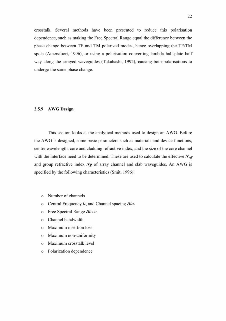
read from Figure 2.4 the ratio dr/w required for -40 dB cross talk level (Smit, 1996). It
is noted that the crosstalk for TE- and TM-polarization may be different as the lateral
index contrast and, consequently, the lateral V-parameter can differ substantially for
the two polarizations. However, since BCB polymer has a low birefringence, crosstalk
for TE- and TM-polarization would give nearly the same result.
24
Figure 2.4 Crosstalk resulting from the coupling between two adjacent receiver channels (Smit, 1996)
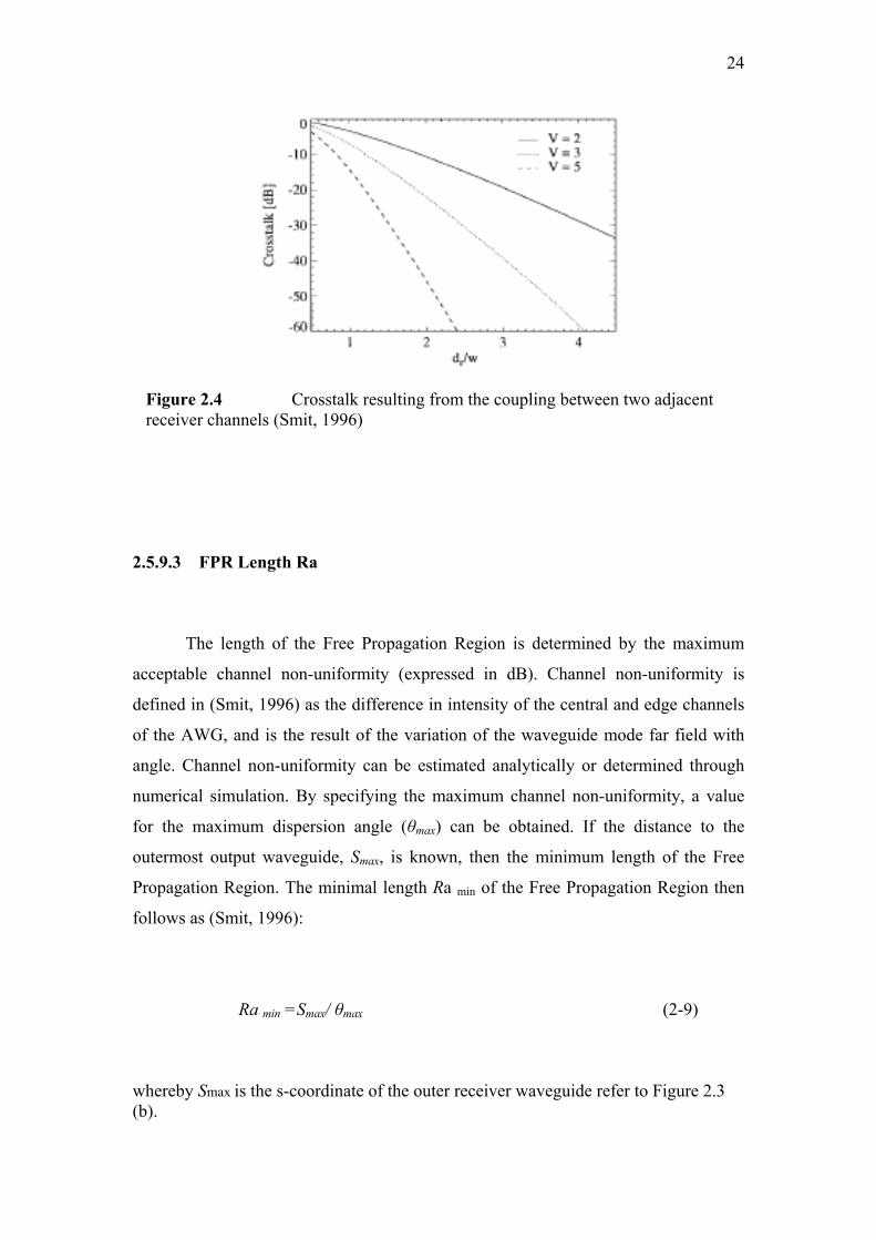
2.5.9.3 FPR Length Ra
The length of the Free Propagation Region is determined by the maximum
acceptable channel non-uniformity (expressed in dB). Channel non-uniformity is
defined in (Smit, 1996) as the difference in intensity of the central and edge channels
of the AWG, and is the result of the variation of the waveguide mode far field with
angle. Channel non-uniformity can be estimated analytically or determined through
numerical simulation. By specifying the maximum channel non-uniformity, a value
for the maximum dispersion angle (θmax) can be obtained. If the distance to the
outermost output waveguide, Smax, is known, then the minimum length of the Free
Propagation Region. The minimal length Ra min of the Free Propagation Region then
follows as (Smit, 1996):
Ra min =Smax/ θmax (2-9)
whereby Smax is the s-coordinate of the outer receiver waveguide refer to Figure 2.3 (b).
25
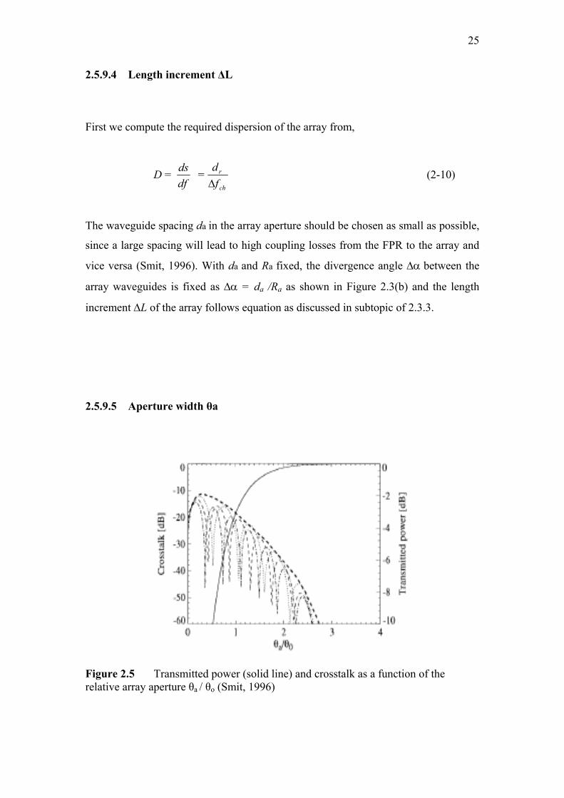
2.5.9.4 Length increment ΔL
First we compute the required dispersion of the array from,
D = dfds =
ch
r
fd
Δ (2-10)
The waveguide spacing da in the array aperture should be chosen as small as possible,
since a large spacing will lead to high coupling losses from the FPR to the array and
vice versa (Smit, 1996). With da and Ra fixed, the divergence angle Δα between the
array waveguides is fixed as Δα = da /Ra as shown in Figure 2.3(b) and the length
increment ΔL of the array follows equation as discussed in subtopic of 2.3.3.
2.5.9.5 Aperture width θa
Figure 2.5 Transmitted power (solid line) and crosstalk as a function of the relative array aperture θa / θo (Smit, 1996)

26
The angular half width θa of the array aperture should be determined using a
graph like Figure 2.5 (adapted for the specific waveguide structure used).
2.5.9.6 Number of array waveguides Na.
The choice of θa fixes the number of array waveguides (Smit, 1996):
1/2 += aaa dRNa θ (2-11)
where Na is number of waveguide
da is spacing between array waveguide
Ra is the length of FPR
2.6 Polymer Material
Polymer waveguide technology has a great potential for economic mass
production of complex planar photonic circuits that comply with the severe
requirement imposed by applications in communication systems. Due to its low cost
from the availability of a wide range of cheap optical polymer and simplicity of
fabricating waveguides from them, polymer has been widely use for optical devices.
Polymer can be deposited over most subtracts including semiconductor
material. Polymer material has low refractive index spreading rate in millimetre and
27
infrared wave. Optic polymer waveguide structure is made by fabrication techniques
suitable with electronic semiconductor such as lithographic photo and RIE (N. Razali,
2005).
For this design, AWG based on WDM system the Benzocyclobutene (BCB
4024-40) polymer has been used. This polymer has several advantages as follow (Liu
et al, 2005):
o Low optical losses.
o Low wavelength dispersion.
o Low birefringence which indicate a lack of molecular orientation in the
optical properties. Birefringence is the difference between the refractive
indices of a material at two different polarizations (eg. TE and TM
polarization).
o Good thermal stability (Tg >350oC).
o Propagation loss of 0.8 dB/cm at 1300 nm and 1.5 dB/cm at 1550 nm.
o Resistant to humidity.
o Good adhesion properties.
o Simplicity and flexibility of waveguide fabrication process.
o Low cost.
Since BCB-4024 polymer offers advantages such as low birefringence, good
thermal stability and low wavelength dispersion (Liu et al, 2005), it has been chosen
as material in this project. BCB polymer becomes an attractive material and has been
used for fabrication various optical devices for instance optical switching (Cao et al),
polymeric optical waveguide (Gang et al, 2005) and multimode interference optical
splitter (M. H. Ibrahim et al, 2006).
Cao et al demonstrated optical bistability and all-optical switching in BCB
polymer micro-ring resonators. 2 pm on- and off-switching responses in frequency
domain were achieved using a tunable cw laser through a high Q BCB micro-ring

67
REFERENCES A. Sugita, A. Kaneko, K. Okamoto, M. Itoh, A. Himeno, and Y. Ohmori, (2000). Very
Low Insertion Loss Arrayed Waveguide grating with Vertically Tapered
Waveguides. IEEE Photonics Tech. Letters, Vol. 12, No. 9 : 1180-1182.
A. Driessen, et al. (2004). Polymer-Based Integrated Optics Devices. In: Nalwa, H. S.
ed. Polymer Optical Fibers. USA: American Scientific Publishers : 73-98
Apollo Photnics. APSS Apollo Application Note on Array Waveguide Grating (AWG)
Design, simulation and layout. Hamilton, Canada.
C. Dragone, (1991). An N x N optical multiplexer using a planar arrangement of two star
couplers. IEEE Photon. Technol. Lett., vol. 3, pp. 812–815.
C. J. Leo, P. V. Ramana and K. Sudharsanam, (2003). Design of polymer arrayed
waveguide gratings for access network and CWDM applications. Electron. Pack.
Techno. Conf : 647-651.
Dr. Martin Amersfoort, “Array Waveguide Grating”, Application note A1998003,
Concept to volume, 1998.
H. Uetsuka, (2004). AWG Technologies for Dense WDM Applications. IEEE J. Select.
Topic Quantum Electron. Vol. 10, No. 2: 393-402.
H. C. Woei, N. A. Rahman and S. Shaari, (2004). Conventional Arrayed Waveguide
Grating with 4 Channel Structure Design for CWDM. ICSE2004 Proc.2004,
Kuala Lumpur, Malaysia. IEEE: 473-476.
J. Jiang, C. L. Callender, C. Blanchetiere, J. P. Noad, S. Chen, J. Ballato, and D. W.
Smith Jr., (2006). Arrayed Waveguide Gratings Based on Perfluorocyclobutane

68
Polymers for CWDM Applications. IEEE Photonics Tech. Letters, vol. 18, No. 2:
370-372
K. Shimomura and Y. Kawakita, (2005). Wavelength Selective Switch Using Arrayed
Waveguides with Linearly Varying Refractive Index Distribution. IPAP Book 2:
341-354
K. Maru, M. Okawa, K. Matsui, and H. Uetsuka, (2002). Statistical Analysis of
Correlated Phase Error in Transmission Characteristics of Arrayed Waveguide
Gratings. IEEE J. of Select. Topics in Quantum Electrons. Vol. 8, No 6 : 1142-
1147
L. Eldada, (2002). Polymer integrated optics: promise vs. practicality. Proc SPIE 4642:
11-22.
L. H. Spiekman and M. R. Amersfoort, (1996). Design and Realisation of polarization
independent phased array wavelength demultiplexers using different array orders
for TE and TM. J Lightwave Technol., Vol. 14, 991-995.
M. Kohtoku (2000). Semiconductior Arrayed Waveguide Gratings for Integrated
Photonic Devices, Electronic and Communications in Japan, part 2, Vol. 8 No.8.
M. K. Smit (2001). Fundamental and Applications of Phasar Demultiplexers, Euro
Conference on Optical Communications. Amsterdam: 2-3
M. K. Smith and C. Van dam, (1996). PHASAR-based WDM-Devices: Principles,
Design and Applications, IEEE J. Select. Topic Quantum Electron. Vol 2, No. 2:
236-250.
M. Kien and S. Shaari, (2000). Design implementation of up to 20 channel silica based
AWG WDM. ICSE 2000 Proceedings: 235-240

69
M. Okawa, K. Maru, H. Uetsuka, T. Hakuta, H. Okano, and K. Matsumoto, (1998). Low
Loss and Wide Passband Arrayed Waveguide Grating Demultiplexer.
ECOC’98, 20-24 September. Madrid, Spain: 323-324.
M. K. Smit, Progress in AWG Design and Technology”, IEEE Fellow.
M. Nebeling, (2002). CWDM: Lower cost for more capacity in the short haul: Fiber
Network Engineering.
M. H. Ibrahim, N. Mohd Kassim, A. B. Mohammad and M. K. Chin, (2006). Design of
Multimode Interference Optical Splitter Based on BenzoCyclobutene (BCB4024-
40) Polymer. Regional Postgraduate Conference on Engineering and Science
(RPCES 2006), 219-221.
N. M. Kassim, A. B. Mohammad, A. B. Supa’at, M. H. Ibrahim and S. Y. Gang, (2004).
Polymer Material for Optical Devices Application, RF ad Microwave Conference,
5-6 October. Selangor, Malaysia: IEEE, 277-280.
N. Razali (2005). Parutan Pandu Gelombang Tersusuin (AWG) Polimer 4, 8 dan 16
Saluran Untuk Jalur C+L. Msc. Thesis, Universiti Kebangsaan Malaysia.
Photeon Technologies, (2005). Application Note: Array Waveguide Gratings. from
www.photeon.com.
Q. Liu, K.S. Chiang and P. Lor (2005). Long-period gratings in polymer ridge
Waveguides. OPTICS EXPRESS 1150, Vol. 13, No. 4.
RBN Inc. (2002). Characteristics of CWDM. Roots, Current Status & Future
Opportunities. from www.rbni.com.

70
S. Lu, C. Yang, Y. Yan, G. Jin, Z. Zhou, W. H. Wong, and E. Y. B. Pun, (2005). Design
and fabrication of a polymeric flat focal arrayed waveguide grating. Optic Express
9982, Vol. 13, No. 25
S. Song, Member IEEE, and Z. WuA, “Broadband Integrated Services Network
Architecture Based on DWDM”, Department of Physics and Computing Wilfrid
Laurier University
S. Y. Gang, N. Mohd Kassim, A. B. Mohammad and M. H. Haniff, (2004). Fabrication of
Polymeric Optical Waveguides by B-Staged Bisbenzocyclobutene (BCB). ICSE
2004 Proc. 2004, Kuala Lumpur, Malaysia. 522-526.
V. K. Stamatios, (2000), Introduction to DWDM technology. New Jersey: IEEE Press.
W. Cao, C. Y. Chen, J. Goldhar, W. Herman and C. H. Lee. Optical bistability and
picosecond optical switching in bisbenzocyclobutene (BCB) polymer microring
resonators. Physical Sciences ond Electrical and Computer Engineering
Deportment at University of Maryland.
Y. Hibino, (2002). Recent Advances in High-Density and Large-Scale AWG
Multi/Demultiplexers With Higher Index-Contrast Silica-Based PLCs. IEEE J.
Select. Topics in Quantum Electron. Vol. 8, No. 6 : 1090-1101.
Y. Hibino, (2000). An Array of photonic filtering advantages: arrayed waveguide grating
multi/demultiplexers for photonic networks. IEEE Circuits & Devices. Vol. 16.
No. 6 : 21-27
Y. Kawakita, T. Saitoh, S. Shimotaya, and K. Shimomura, (2004). A Novel Straight
Arrayed Waveguide Grating With Lenearly Varying Refractive-Index
Distribution. IEEE Photonics tech. Letters. Vol. 16, No. 1 : 144-146.