Embed Size (px)
Citation preview

Umashankar Vishnoi et al. 2015, Volume 3 Issue 6 ISSN (Online): 2348-4098 ISSN (Print): 2395-4752
International Journal of Science,Engineering and Technology
An Open Access Journal
© 2015 Umashankar Vishnoi et al. This is an Open Access article distributed under the terms of the Creative Commons Attribution License (http://creativecommons.org/licenses/by/4.0), which permits unrestricted use, distribution, and reproduction in any medium, provided the original work is properly credited.
Stability Analysis of Multi-Machine SMIB System 1Umashankar Vishnoi, 2B. S. S. P. M. Sharma
Introduction
Synchronous machine is represented by voltage source in back of transient reactance that is constant in magnitude but change in angular position this representation neglect the effect of saliency and assume constant flux linkage and small change in speed if machine rotor speed is assumed constant at synchronous speed machine due to such effect as windage and friction are ignored mathematical model is described by following set of equation following calculation require:
(a) Transient stability analysis is to solve initial load flow,
(b) Initial bus voltage magnitude,
(C) Phase angle,
(D) Machine current.
[I] = [V] [Y]
[V] = [I] [Y]
The help of symmetrical fault analysis we By obtain
Y = 1/z 1
1 Corresponding Author Email: [email protected]
Where
V= vector of bus voltage
I=vector of bus current
Z= impedance of matrix
Y=admittance of matrix
II = Si/ Vi* = (Pi – jQi)/Vi*,
i= 1,2,3,…..m (a)
Where
m is the number of generators,
Vi is the terminal voltage of the ith generator Pi and Qi are the generator real and reactive powers.
All unknow values are determined from the initial power flow solution. The generator armature resistances are usually neglected and the voltages behind the transient reactances are then obtained [6],
Ei=Vi + jXdIi (b)
Next, all load are converted to equivalent admittances by using the relation
Yio = Si*/Vi
2 = (Pi – jQi)/Vi2 (c)
Abstract
Transient stability analysis has always been an issue of paramount important in power system planning and operation. Basically stability analysis method may be categorized by two major stability analysis methods. A small signal stability and transient stability transient stability method can be further divided into numerical integration and direct method. Many techniques have been proposed for transient stability analysis in power system. Purpose of this paper is to study and investigate transient stability analysis is extended for transient stability analysis of multi-machine power system. It is a tool to identify stable and unstable condition of power system after fault clearing by the help of differential equation.
Keywords- Multi-machine Power System, MATLAB Simulink, Transient Stability, Damping Numerical Method, Swing Equation.
88
Umashankar Vishnoi et al. International Journal of Science, Engineering and Technology, 2015, Volume 3 Issue 6 ISSN (Online): 2348-4098 , ISSN (Print): 2395-4752
To include voltages behind transient reactances, m buses are added to the n bus power system network.
Figure 1: Power system representation for multi machine stability studies
Theory
Perfault bus matrix
In this system one generator is taken as reference generator and other two are studied for stability purposes. Fault occurs at point P in the system, and two loads are connected to the system at Sd1 and Sd2.
Ibus = Ybus Vbus (d)
Where, Ibus is the vector of the injected bus currents
Vbus is the vector of bus voltages measured from the reference node
B--- Charging reactance of the system
During Fault Bus Matrix
Since the fault is near the bus, so it is short circuited to ground.
Ybus = Yjold – Ynold Ynjold /Ynnold (g)
Now we obtain prefault bus matrix by deleting 4th row and 4th column by using the relationship (g), then we obtain reduced bus matrix (3x3), then bus no 2 decouple from other during fault and bus 3 is directly connected to bus 1 showing fault at bus 4 is zero.
Post Fault Bus Matrix
By opening circuit breaker at either end, fault is cleared prefault bus has to be modified again this is done by substituting Y54 = y45 = 0 and substituting the series admittance of line 4-5 and capacitive susceptance of half line from Y44 and Y55.
Condition: Generator 1 and 2 are not connected when line 4-5 is removed.
Ypostfault = Yjjold – Yjj – Bij/2 (h)
The diagonal elements of the bus admittance matrix are the sum of admittances connected to it.
During fault Power Angle Equation
Pe2 = 0
Pe3 = Re[ Y33E3E* + E3* Y31E1]
Since Y32 = 0
= (E3’)2 G33+ E1
’E3’ Y31 cos(δ31 – θ31)
Pe3 = 0.1561 + 5.531 sin(∆3 – 0.755) (i)
Post fault power angle equations
Pe2 = E22 G22 + E1 E2 Y21 cos(δ21 – θ21) (j)
Pe3 = E32 G33 + E1 E3 Y31 cos (δ31 – θ31) (k)
Pe3 =0.1823┼6.5282sin(∆3-0.8466)
Swing equations during fault
Pa(n-1) =Pm-Pmaxsin∆n-1
D2δ2/dt2 = 180f/H2 (Pm2 – Pe2) = 180f/H2 Pa2’ (l)
D2δ3/dt2 = 180f/H3 (Pm3 – Pe3) (m)
Swing equation post fault
D2δ2/dt2 = 180f/11[3.25- {0.6012 +8.365 sin (δ2 – 1.662o)}] (n)
D2δ3/dt2 = 180f/9 [2.10-{0.1823+6.5282 sin (δ3 – 0.8466o)}] (o)
Pa = Pm - Pc – Pmax sin(δ – γ) (p)
The above swing equations can be solved by point to point.
Results and Tables
By using all the mathematical equations, the Simulink diagram for multimachine stability is generated. The Simulink diagram is highly complicated so it is divided into subsystem (A) and subsystem (B)
Following parameter are used in simulation
89

Umashankar Vishnoi et al. International Journal of Science, Engineering and Technology, 2015, Volume 3 Issue 6 ISSN (Online): 2348-4098 , ISSN (Print): 2395-4752
Parameters Values
E1 -1.0
E2 1.03
E3 1.02
G3 17.44
G2 0
G4 0
G1(CONSTANT) 13.08
Y21 -0.2214+j*7.6289
Y22 0.5+j*7.7895
Y23 0
D1 0
From fig B, Pe2 =electromechanical power for machine (a), From fig A Pe1= electromechanical power for machine (b), Switch; used for post-fault and pre-fault.
We get output by the help of multi-machine system.
First we calculate pre-fault data, determine E voltage behind transient reactance for machine a,b.
During faulted mode determine generator output from power angle equation. After it we solve swing equation according to equation completely and determine post fault and line removing point, after it we draw the swing curve it is varying by vary critical clearing time of system.
Stability of both machines will depend upon oscillation
Oscillation increase = stability decrease
Oscillation decrease= stability increase
Stability is inversely proportional to oscillation
We plotted many curve torque angle and time.
Figure 2: subsystem 1 of multi-machine power system
Figure 3: Machine 2 sub-systems is similar to machine 1 shown in figure 2
90
Umashankar Vishnoi et al. International Journal of Science, Engineering and Technology, 2015, Volume 3 Issue 6 ISSN (Online): 2348-4098 , ISSN (Print): 2395-4752
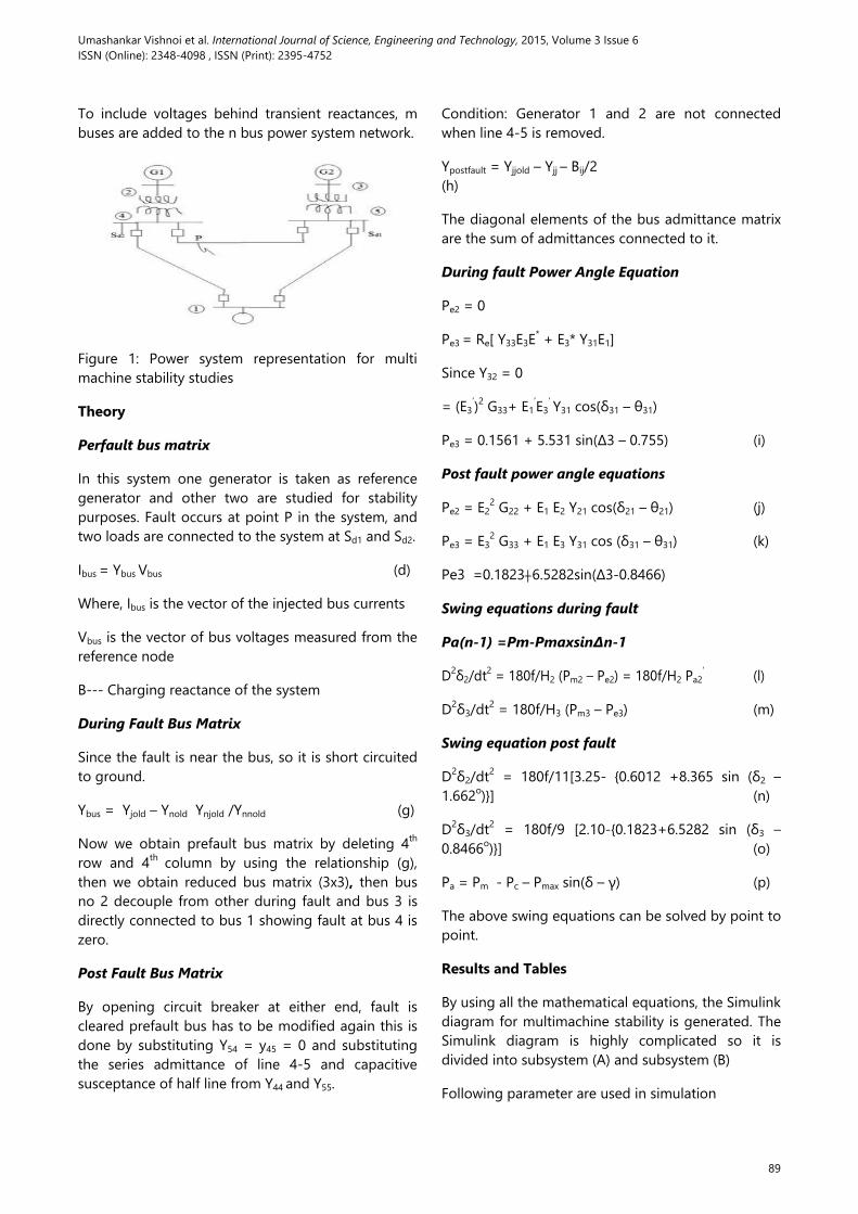
Figure 4: Multi-machine power system
Now we draw the output response of multi-machine. We draw the curve between torque angle and time.
When critical clearing time is less then both machines will stable.
When critical clearing time is more than both machines will unstable.
We draw many curves for different-different Critical clearing time.
Tc increase = un-stability increase
Tc decrease = stability increase
Tc = critical clearing time
0.4
0.11
91
Umashankar Vishnoi et al. International Journal of Science, Engineering and Technology, 2015, Volume 3 Issue 6 ISSN (Online): 2348-4098 , ISSN (Print): 2395-4752
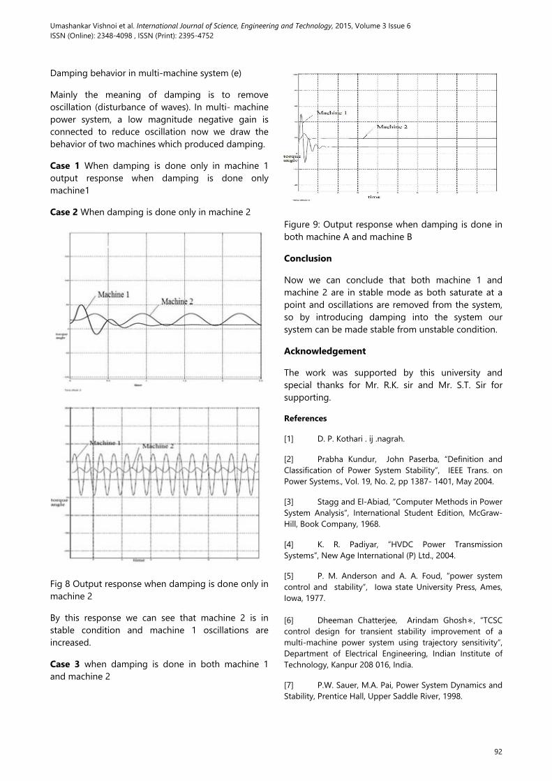
Damping behavior in multi-machine system (e)
Mainly the meaning of damping is to remove oscillation (disturbance of waves). In multi- machine power system, a low magnitude negative gain is connected to reduce oscillation now we draw the behavior of two machines which produced damping.
Case 1 When damping is done only in machine 1 output response when damping is done only machine1
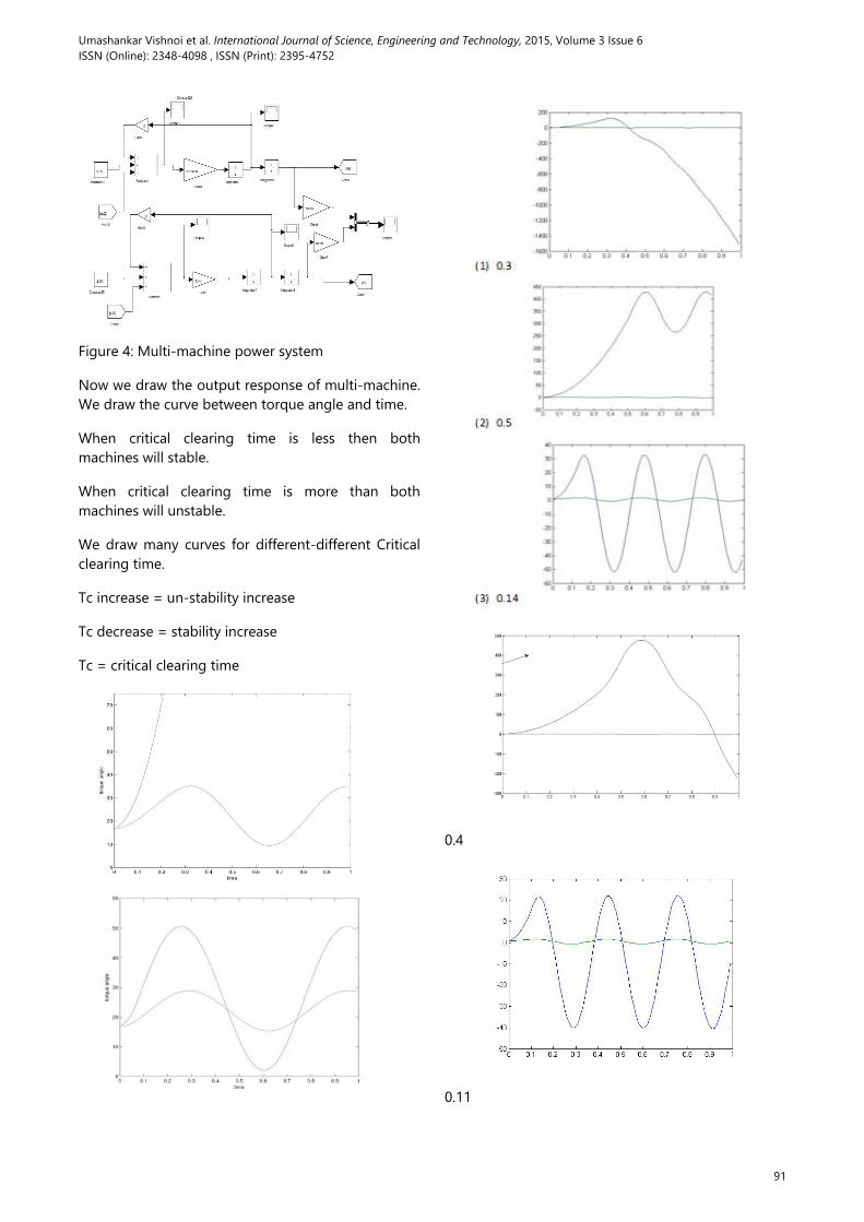
Case 2 When damping is done only in machine 2
Fig 8 Output response when damping is done only in machine 2
By this response we can see that machine 2 is in stable condition and machine 1 oscillations are increased.
Case 3 when damping is done in both machine 1 and machine 2
Figure 9: Output response when damping is done in both machine A and machine B
Conclusion
Now we can conclude that both machine 1 and machine 2 are in stable mode as both saturate at a point and oscillations are removed from the system, so by introducing damping into the system our system can be made stable from unstable condition.
Acknowledgement
The work was supported by this university and special thanks for Mr. R.K. sir and Mr. S.T. Sir for supporting.
References
[1] D. P. Kothari . ij .nagrah.
[2] Prabha Kundur, John Paserba, “Definition and Classification of Power System Stability”, IEEE Trans. on Power Systems., Vol. 19, No. 2, pp 1387- 1401, May 2004.
[3] Stagg and El-Abiad, “Computer Methods in Power System Analysis”, International Student Edition, McGraw- Hill, Book Company, 1968.
[4] K. R. Padiyar, “HVDC Power Transmission Systems”, New Age International (P) Ltd., 2004.
[5] P. M. Anderson and A. A. Foud, “power system control and stability”, Iowa state University Press, Ames, Iowa, 1977.
[6] Dheeman Chatterjee, Arindam Ghosh∗, “TCSC control design for transient stability improvement of a multi-machine power system using trajectory sensitivity”, Department of Electrical Engineering, Indian Institute of Technology, Kanpur 208 016, India.
[7] P.W. Sauer, M.A. Pai, Power System Dynamics and Stability, Prentice Hall, Upper Saddle River, 1998.
92

Umashankar Vishnoi et al. International Journal of Science, Engineering and Technology, 2015, Volume 3 Issue 6 ISSN (Online): 2348-4098 , ISSN (Print): 2395-4752
Dheeman Chatterjee , Arindam Ghosh*, “Application of Trajectory Sensitivity for the Evaluation of the Effect of TCSC Placement on Transient Stability” International Journal of Emerging Electric Power Systems, Volume 8, Issue 1 2007 Article 4, The Berkeley Electronic.
Author’s Affiliation 1, 2 Department of Electrical Engineering, Mewar University, Gangrar, Chittorgarh, Rajasthan, INDIA, E-mail: [email protected]
Copy for Cite this Article- Umashankar Vishnoi and B.S.S.P.M.Sharma, ‘Stability Analysis of Multi-Machine SMIB System’, International Journal of Science, Engineering and Technology, Volume 3 Issue 6: 2015, pp. 88- 93.
Submit your manuscript to International Journal of Science, Engineering and Technology and benefit from:
Convenient Online Submissions
Rigorous Peer Review
Open Access: Articles Freely Available Online
High Visibility Within The Field
Inclusion in Academia, Google Scholar and Cite Factor.
93


![Stability Enhancement of Multi-Machine Power System … · the PV and wind plants in the power system stability [9]. This motive us to evaluate the proposed control system considering](https://img.dokumen.tips/doc/110x75/5e7f7cd6da4ce2213a2299da/stability-enhancement-of-multi-machine-power-system-the-pv-and-wind-plants-in-the.jpg)