Embed Size (px)
Citation preview

© 2016 Hydro International
An introduction to vortex flows and their implications on solid-liquid separation
Dr Daniel Jarman Technology Manager, Hydro International

hydro-int.com
Defining vortex behaviour is difficult.
There is often ambiguity in what constitutes vortex behaviour, and common descriptions are qualitative in nature and therefore necessarily limited.
It has become common to identify quantitative features associated with vortices in order to provide a definition.
Theoretical vortex behaviours are useful as a starting point.
Theoretical vortex behaviours provide a foundation of understanding, and it is helpful to examine the vortex core region to illustrate dominant features.
Two theoretical behaviours exist: free and forced motion.
In a real fluid, however, neither the forced nor the free vortex behaviours prevail—meaning that theoretical behaviours are of limited practical application.
An understanding of real vortex behaviours is essential for effective real-world application.
In real fluids some blending between the forced and free vortex behaviours is always observed, though in the vast majority of real-world engineering (high Reynolds number/turbulent) flows there is a strong tendency to exhibit free vortex behaviour, whereas the dominance of forced vortex behaviour is only observed in the vortex core and in lower Reynolds number flows.
Understanding vortex behaviours enables effective, efficient real-world hydrodynamic separation.
A full understanding of real-world vortex behaviour enables engineers to develop hydrodynamic separators that minimise short circuiting and maximise the residence time of the fluid, ensuring that the best use is made of the available treatment volumes.
With this understanding, separation units can be designed to be resistant to changes in inflow conditions, enabling them to collect targeted materials across a wide range of flow rates.
THREE DESIGN BENEFITS THAT RESULT FROM UNDERSTANDING VORTEX BEHAVIOUR
Minimise short circuiting
Cutting short circuiting means that a smaller tank is required, with reliable performance at varying flow rates.
Extend residence time of solids
Increased residence time of solids leads to better performance and/or the need for a smaller separation vessel.
Sweep solids to a central location for collection
Using the vortex to sweep solids means that no mechanical components are required – reducing power and maintenance need, and making the system resilient against FOG and rags.
Executive Summary
hydro-int.com
1. DEFINITION OF A VORTEX
There is often ambiguity in what constitutes vortex behaviour.
A common description of a vortex is a swirling coherent structure in the flow that has time and length scales that are greater than the background scale of turbulence, however this only presents a qualitative definition.
The vortex behaviour induced in vortex flow controls and vortex separators is generally referred to as ‘concentrated’ vortex behaviour, as the vortex scale is of a similar scale to the device geometry.
2. THEORETICAL BEHAVIOURS
Due to the difficulties in defining vortex behaviour it has become common to identify quantitative features associated with vortices.
As a starting point it is helpful to distinguish between the behaviour of the vortex core for real fluids and ideal fluids (a fluid with no viscosity), as this is where the most significant differences are evident.
2.1 FORCED VORTEX
For a real fluid the vortex core is defined as the region of the flow field where solid body rotational or forced vortex behaviour is dominant.
This behaviour occurs due to the viscous forces in the fluid becoming significant compared to the inertial forces.
The local Reynolds number is the ratio of the inertial force and viscous force in the fluid.
A low Reynolds number indicates a relatively larger viscous force, signifying the tendency to behave more like a solid body. Low Reynolds number flows will therefore tend to exhibit a forced vortex behaviour i.e. at the vortex core.
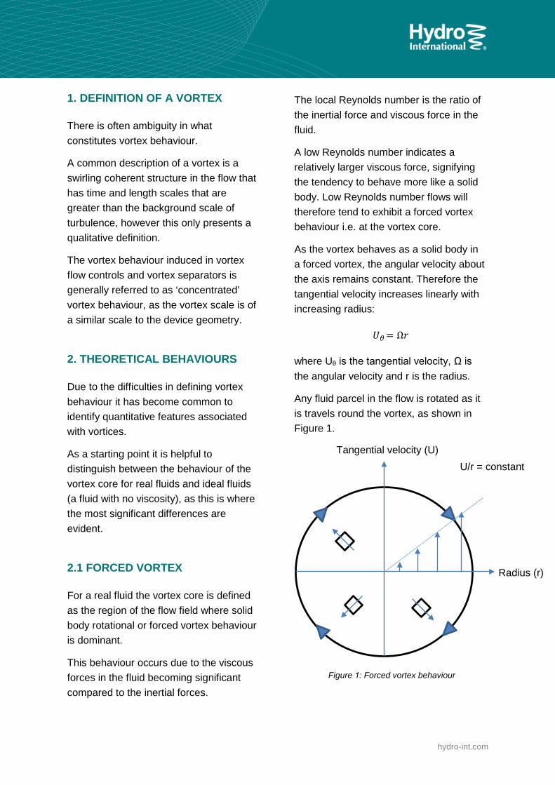
As the vortex behaves as a solid body in a forced vortex, the angular velocity about the axis remains constant. Therefore the tangential velocity increases linearly with increasing radius:
𝑈𝑈𝜃𝜃 = Ω𝑟𝑟
where Uθ is the tangential velocity, Ω is the angular velocity and r is the radius.
Any fluid parcel in the flow is rotated as it is travels round the vortex, as shown in Figure 1.
Figure 1: Forced vortex behaviour
Radius (r)
Tangential velocity (U) U/r = constant

hydro-int.com
For this reason a forced vortex is also called a rotational vortex.
2.2 FREE VORTEX
When the Reynolds number of the flow is large the effect of the viscosity of the fluid becomes small.
Taking this behaviour to its limit, the effect of the viscosity becomes negligible and the flow behaves in an inviscid manner (with no viscosity).
This results in another behaviour, normally called a free vortex.
In a free vortex the angular momentum remains constant (for steady conditions) in accordance with Newton’s second law for a body without any influencing forces:
𝜌𝜌𝜌𝜌𝑈𝑈𝜃𝜃 ∗ 2𝜋𝜋𝑟𝑟 = k
where ρ is the fluid density and A is the flow area.
This can be simplified to:
2𝜋𝜋𝑟𝑟𝑈𝑈𝜃𝜃 = Γ
where Γ is the called the circulation value, which is constant for a free vortex.
Looking at this equation it can be seen that velocity varies inversely to the radius:
𝑈𝑈𝜃𝜃 =Γ
2𝜋𝜋𝑟𝑟
The difference in velocity between the inner and outer edge of a fluid element being carried in the flow causes it to retain its rotational orientation regardless of its position in the vortex, as shown in Figure
2. For this reason a free vortex in alsocalled an irrotational vortex.
Figure 2: Free vortex behaviour
Both the free and forced vortex behaviours cannot prevail in a real fluid as the velocity will approach infinity with increasing or decreasing radius for the forced and free vortex behaviours respectively. This is obviously not a realistic outcome.
3. REAL BEHAVIOUR
In real fluids some blending between the forced and free vortex behaviours is always observed.
The simplest complete model for describing real fluid behaviour was devised by Rankine, which is a switch between the forced and free vortex behaviours.
Radius (r)
Tangential velocity (Ω)
Ω.r = constant

hydro-int.com
The tangential velocity profile for a real vortex compared to Rankine’s model is shown in Figure 3.
The transition towards the forced vortex behaviour is often called the 'core region' and occurs near the vortex axis, whereas the free vortex behaviour in the outer region is called the 'tail'.
The peak velocity occurs near the outer edge of the vortex core.
Rankine’s model has shown to be a good approximation to reality in many cases, however a number of distinct vortex behaviours can arise which are more complex.
Figure 3: Real vortex behaviour
Difficulties occur in predicting the behaviour for vortex flows in real fluids when establishing the transition between these two types of motion. This transition is governed by the fluid viscosity and the viscous-like behaviour of turbulent stresses in the flow. Due to this issue
several methods for the identification of inviscid vortices have evolved based on the presence of free- and forced-vortex behaviours.
The most intuitive vortex identification methods are summarised below:
Minimum local pressure
As vortices have an associatedpressure drop towards their axis, theymay be identified according to a localminimum pressure value. A significantissue relating to the application of thisidentification method is that thepressure drop is dependent on thescale and magnitude of the vortices,making selecting an appropriatepressure threshold value problematic.
Velocity streamlines
A set of velocity streamlines in aclosed tube surrounded by fluid withzero vorticity can be used to locatevortices. This definition only strictlyapplies to an ideal fluid, but is stilluseful for identifying vortices inmedium to low viscosity fluids.
Vorticity magnitude
Identifying local maxima in thevorticity magnitude is one of the mostwidely and successfully appliedmethods for characterising vortices.
In the case of most engineered flow systems the challenge of accurate vortex identification is often not an issue, as the vortex behaviour is induced by the device geometry and so is easily identified.
Radius (r)
Tangential velocity (Ω)

hydro-int.com
In the vast majority of engineered systems, including vortex separators, the Reynold’s number will be high indicating a strong tendency to exhibit free vortex behaviour.
In reality, the dominance of forced vortex behaviour is only observed in the vortex core and in lower Reynolds number flows. These areas are typically in the boundary layer region and exist only within a few millimetres from a fixed boundary or wall.
Forced vortex behaviours can also dominate in rotating mechanical systems, such as a rotating outer wall on a cylindrical vessel.
4. VORTICES IN HYDRODYNAMICSEPARATORS
Vortices are harnessed in solid-liquid separation processes for three main purposes:
1. The rotational behaviour can help tominimise short-circuiting and helpmaximise the fluid residence time.
2. The centrifugal force created by therotational motion can be manipulatedto extend or shorten the residencetime of particles in the flow relative tothe fluid residence time.
3. The swirling motion creates asweeping action on surfaces normalto the axis of the vortex that can beused to collect material at a centrallocation.
The following subsections discuss these mechanisms in more detail.
4.1 FLUID RESIDENCE TIME
The swirling flow behaviour extends to fill the limits of the bounding device geometry minimising short circuiting and therefore maximising the residence time of the fluid.
This ensures that the best use is made of the available volumes.
Rotational flows are also relatively stable and similar flow patterns prevail over a wide range of flow rates, making them resistant to changes in inflow conditions.
4.2 PARTICLE RESIDENCE TIME
The circular path of the flow in a vortex can be used to enhance separation. This is due to the fact that circular motion will cause a centrifugal force (Fc) to be exerted on the particle.
For example, the flow in the Grit King® separator is introduced tangentially.
This causes any particles being carried by the flow to follow a rotary path and experience a centrifugal force.
The particle also experiences a drag force (Fd) that causes the particle to be carried towards the centre of the vortex, where the flow exits at the overflow.
When the centrifugal and drag forces are balanced there is no radial motion of the particles and they travel in a perfect circle, maximising the time that they spend in the chamber (residence time) and enhancing the sedimentation process.
hydro-int.com
The gravitation force (Fg) on the particles then ensures the particles settle within the system, removing them from the flow.
Where a particle is denser than the fluid the centrifugal force will tend to move it to the outer edge of the vortex.
If the particle density is less than the fluid the centrifugal force will tend to carry the particle towards the axis of the vortex.
Processes that rely on the centrifugal force alone are more intensive and have a smaller footprint, than devices that rely on settling, but more energy is needed to generate the increased centrifugal force; such as in centrifuges or hydro cyclones.
As hydrocyclones have minimal dependence on gravitation force for separation they can remove neutrally buoyant material, or material that is difficult to settle, as long as there is a density difference between the solid and liquid phase.
Hydrodynamic vortex separators use the centrifugal force to increase the residence time of the particles allowing sufficient time for them to settle under gravity. This requires that the particles must be readily settable. This is the type of behaviour that occurs in separators such as the Grit King® and Hydro International’s grit washing systems.
The ratio between the centrifugal and gravitational forces (Fc/Fg) is a key metric for characterising the behaviour of vortex separators.
The greater this ratio is the more energy is imparted to the fluid and the greater the headloss.
High energy processes are generally more intensive separation process and require a smaller device footprint or volume.
This is because the energy of the flow is being used to enhance the separation process.
An Fc/Fg ratio of 2 indicates that a centrifugal force equivalent to twice the gravitational force is being generated.
To illustrate this we can look at a continuum of different vortex separation devices and examine how the geometry of each device capitalises on different features of vortex behaviour.
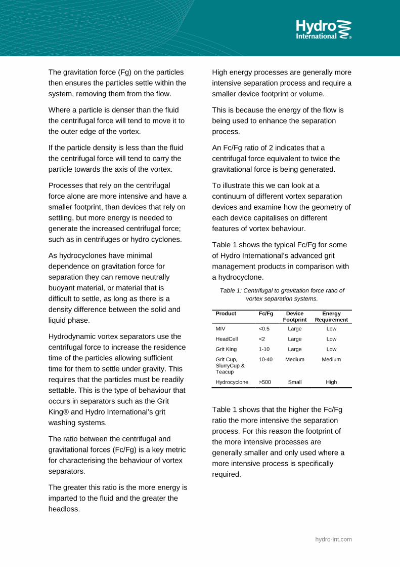
Table 1 shows the typical Fc/Fg for some of Hydro International’s advanced grit management products in comparison with a hydrocyclone.
Table 1: Centrifugal to gravitation force ratio of vortex separation systems.
Product Fc/Fg Device Footprint
Energy Requirement
MIV <0.5 Large Low
HeadCell <2 Large Low
Grit King 1-10 Large Low
Grit Cup, SlurryCup & Teacup
10-40 Medium Medium
Hydrocyclone >500 Small High
Table 1 shows that the higher the Fc/Fg ratio the more intensive the separation process. For this reason the footprint of the more intensive processes are generally smaller and only used where a more intensive process is specifically required.

hydro-int.com
4.3 CENTRAL COLLECTION OF MATERIAL
A subtle sweeping effect of the flow towards the vortex axis is encountered on surfaces normal or inclined to the vortex axis, such as in the HeadCell® trays or on the base of the Grit King® or MIV.
As flow passes over a boundary, such as a riverbed, the friction of the flow against the bed causes the flow near the bed to move more slowly than the freestream flow. This region is called the boundary layer.
The effect of this velocity difference ‘shears’ the fluid, creating small vortices which ‘roll’ along the riverbed, as shown in Figure 4. These small vortices are responsible for ripples and dunes on a riverbed.
Figure 4: Boundary layer vortex
The important feature to note is that the boundary layer vortices have a tendency to sweep material in the opposite direction of the freestream flow and the axis of the vortices travel in the direction of the freestream flow.
The vortex axis creates a “vortex line” which travels along the bed with the flow, and in a uniform flow the line will remain perpendicular to the flow.
When this vortex line encounters a bend it will be twisted away from the axis of the bend.
This is due to the fact that the fluid at the inner edge of the bend travels a shorter distance than the fluid at the outer edge before it exits the bend. This twisting process is shown in Figure 5.
This results in a sweeping action towards the centre point of the bends arc. This phenomenon is responsible for the meandering behaviour of rivers.
In a vortex separator the process can be thought of as a continuous bend and results in a sweeping action towards the centre of the vessel. This is the process that is most evident in the HeadCell® (but which is also present in all of Hydro International’s vortex separators), which conveniently allows the material collected to be drawn off at a central underflow.
The freestream velocity of the flow and surface roughness effect the strength and sweeping action of the boundary layer vortices.
Figure 5: Twisting of a vortex line as it passes around a bend
Boundary layer
Boundary
High velocity
Low velocity
Freestream flow direction
Vortex

hydro-int.com
5. VORTEX BEHAVIOUR IN HYDROINTERNATIONAL PRODUCTS
5.1 MIV
The velocity contours through a vertical plane of a mechanically induced vortex (MIV) are shown in Figure 6.
The Fc/Fg ratio is typically less than 0.5 in an MIV. Although the flow enters the main chamber tangentially, the inlet velocity is low and the swirling behaviour is partially dissipated and not well structured, which can lead to short-circuiting and inefficiencies.
The vortex motion has little effect on the settling behaviour of the particles.
The inlet channel and main chamber act purely as a settling tank and vortex motion of the flow itself is not sufficient to sweep the settled material at the base towards the centre of the device.
The vortex motion of the flow at the base of the unit is enhanced by adding rotational energy to the flow using a vertical axis impeller.
This acts to ensure there is a sufficiently well-structured swirling motion on the base of the vessel to sweep collected material to the central collection zone.
Figure 6: Velocity contours in an MIV
5.2 HEADCELL®
In the HeadCell® the primary function of the swirling motion of the flow is used to drive the sediment towards a central collection zone.
Figure 7 shows contours of velocity within a five-tray HeadCell®, where the red regions indicate areas of high velocity.
As the Fc/Fg ratio is less than 2 (Table 1) the swirling motion does little to enhance the separation process by extending the particle retention time.
The settling distance to the tray for a given particle is already small so extending the particle retention time to enhance settling is not required.
The fluid enters the trays tangentially and the kinetic energy of the flow is rapidly dissipated due to the large contact area with the trays.
This results in lower velocities towards the centre of the trays.
The kinetic energy being dissipated on the trays acts to drive the boundary layer vortices that are responsible for sweeping the settable material towards the central collection zone of the vessel.
It is desirable to have a quiescent zone in the centre of the vessel to allow the particles to settle.
There is no distinct concentrated vortex present within the unit (as shown in Figure 7) due to dissipation of the concentrated vortex behaviour into boundary layer vortic es on the tray surfaces.
hydro-int.com
Figure 7: Velocity contours in a HeadCell®
5.3 GRIT KING®
The Grit King® typically operates with an Fc/Fg value of between 2 and 10. This results in a much more pronounced vortex motion than in the HeadCell®, and also slightly increased headloss in order to power the vortex flow.
The centrifugal force on the particles acts to increase the particle residence time and keep the particles in the vessel for longer than the typical flow residence time, giving them a greater chance to settle.
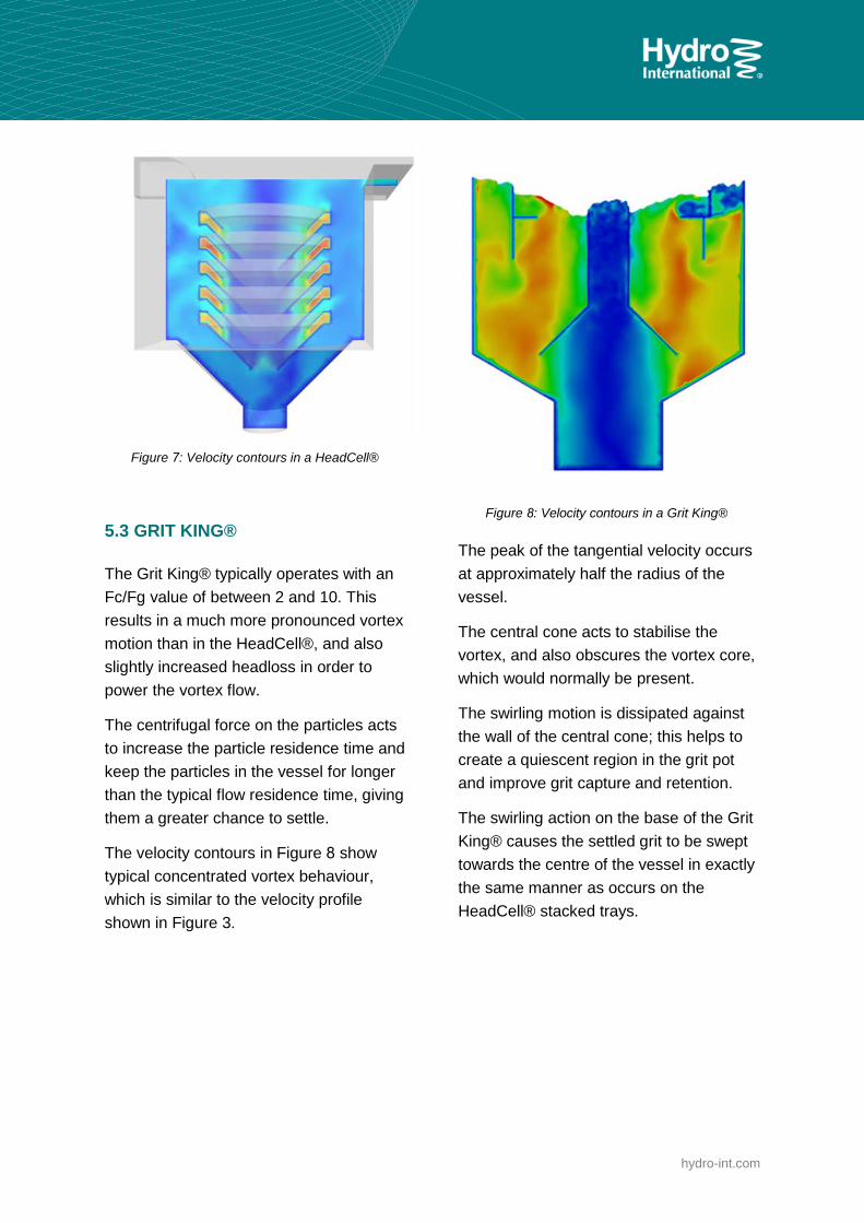
The velocity contours in Figure 8 show typical concentrated vortex behaviour, which is similar to the velocity profile shown in Figure 3.
Figure 8: Velocity contours in a Grit King®
The peak of the tangential velocity occurs at approximately half the radius of the vessel.
The central cone acts to stabilise the vortex, and also obscures the vortex core, which would normally be present.
The swirling motion is dissipated against the wall of the central cone; this helps to create a quiescent region in the grit pot and improve grit capture and retention.
The swirling action on the base of the Grit King® causes the settled grit to be swept towards the centre of the vessel in exactly the same manner as occurs on the HeadCell® stacked trays.

hydro-int.com
5.4 GRITCUP®, SLURRYCUP® & TEACUP®
Grit washing devices such as the GritCup®, SlurryCup® and Tea Cup® use higher energy vortices to generate greater centrifugal forces.
The tangential velocity in the vortex tail increases from the edge of the vessel up to a maximum value at the edge of the vortex core.
The velocity then decreased from the edge of the vortex core as the vortex axis is approached.
This is identical to the velocity profile shown in Figure 9.
The velocity distribution of the SlurryCup® shows a well-defined peak velocity at the radius of the vortex finder.
The vortex finder helps to anchor the vortex and prevent vortex precession, which is a process whereby the vortex core oscillates in a helical fashion.
The precessional pattern within the vortex core can be seen in Figure 7.
The Fc/Fg ratio in the GritCup®, SlurryCup® and Tea Cup® is up to four times higher than that of the Grit King® (10-40). This allows a smaller footprint separation process, but it comes at an additional energy cost which is demonstrated through the increased headloss.
The increased Fc/Fg ratio acts to further extend the particle residence time compared to the fluid, allowing the particles time to settle under gravity.
Figure 9: Velocity contours in a GritCup®
hydro-int.com
6. CONCLUSIONS
Generating a swirling, vortex motion in the flow can be used to enhance separation processes.
This is due to the fact that the vortex motion minimises short circuiting to maximise vessel efficiency.
The residence time of the particles is also increased through the generation of centrifugal forces, allowing them a greater time to settle.
Finally, the vortex motion generates a sweeping action in the boundary layer on the base of the vessel to move collected material to a central location.
The centrifugal force generated within the vortex is related to the tangential velocity.
This means that separation can be enhanced through increasing the tangential velocity, but this will increase the energy demands and headloss of the system.
Selecting the most appropriate system for an application is a balance between two sets of factors:
Device footprint and performance Capital cost and operating cost
A high centrifugal to gravity force ratio will reduce device footprint and capital cost.
Unit selection should be made to address the balance between capital and operating cost for each customer, as well as considering specific unit features.
DESIGN BENEFITS OF UNDERSTANDING VORTEX BEHAVIOUR:
Minimise short circuiting
Cutting short circuiting means that a smaller tank is required, with reliable performance at varying flow rates.
Extend residence time of solids
Increased residence of solids leads to better performance and/or the need for a smaller separation vessel.
Sweep solids to a central location for collection
Using the vortex to sweep solids means that no mechanical components are required – resulting in reduced power and maintenance need. An absence of mechanical components also makes the system resilient against fat, oil and grease (FOG) and rags.
Dr Daniel Jarman is Hydro International’s Technology Manager, and has worked with the company’s Product Development Team for over 10 years, delivering new and enhanced products, guiding technology selection and furthering design expertise.
He received his PhD from the University of Exeter, which focused on the optimisation of the hydraulics of drainage systems and simulation of vortex flows.
He also supervises Hydro International’s academic research projects, which contribute to long-term development strategy and design practices.

© 2016 Hydro International
Visit hydro-int.com to learn more about how Hydro International’s Advanced Grit Management® technology can help you to cut the cost of wastewater grit.


![SUBSONIC FLOWS PAST A PROFILE WITH A VORTEX ...arXiv:2008.06770v1 [math.AP] 15 Aug 2020 SUBSONIC FLOWS PAST A PROFILE WITH A VORTEX LINE AT THE TRAILING EDGE JUN CHEN ZHOUPING XIN](https://img.dokumen.tips/doc/110x75/6054c8959ec3ac20a770a3f8/subsonic-flows-past-a-profile-with-a-vortex-arxiv200806770v1-mathap-15.jpg)